

Page 1

Models E984,0984 and
K984-X8X Controllers
System Planning and
Installation Guide
GM-0984-EDK
Rev. R
I Modicon I Square D 8 Telemecanique
Page 2

Page 3
Modicon
System Planning and
Installation Guide for
984-X8X Controllers
Models E, D, and K
GM-0984-EDK Rev. B
August, 1995
MODICON, Inc.
One High Street
North Andover, Massachusetts 01845
Page 4

Page 5
Preface
This guide describes the ten different yet similar 984 slot mount Programmable
Logic Controllers and their available options, together with procedures for system
planning and installation.
The major differences are identified up front for easy reference in Chapter 1.
Throughout the manual a number of sections apply to all models, while others apply only to certain models as so noted.
The information in this document is subject to change without notice and should
not be construed as a commitment by Modicon, Inc., who assumes no responsibility for any errors that may appear in this document.
No part of this document may
be reproduced in any form or by any means, electronic or mechanical, including
photocopying, without the express written permission of the publisher, Modicon,
Inc. All rights reserved.
0 Copyright 1995 Modicon, Inc.
The following are trademarks of Modicon, Inc.:
ModiconB
P190
984A
984-380
984-38 1
E984-381
984-385
E984-385
Micro 984
984
984B
984480
E984-480
984-485
E984-485
984-680
ModbusB
984X
984-685
E984485
984-780
984-785
984-785L
E984-785
984-l 20
984-l 30
984-l 45
984-351
984-455
Modsoft@
D984-385 K984-485 D984-785
K984-785 Modbus Plus
IBM8 is a registered trademark of International Business Machines, Inc.; IBM PC
is a trademark of International Business Machines, Inc.
Preface iii
Page 6

Objectives
This manual will help you plan, configure, mount, wire, connect, check out, and
troubleshoot your 984 slot-mount controller system, including 984/800 Series
Remote I/O. After reading this book:
o A Control Engineer will be able to identify and physically plan the location and
mounting of system components.
o A Plant Electrician/Installer will be able to install, power-up, and check out the
system.
o A Maintenance Technician will be able to recognize, locate, identify, and re-
solve or report system failures.
How To Use This Manual
Chapter 1 describes the various controllers and their functions.
Chapter 2 offers information for planning your installation.
Chapter 3 is an installation procedure for your controller with local I/O and
Remote I/O.
Appendix A gives system specifications.
Appendix B gives troubleshooting assistance.
iv Preface
Page 7
Related Documents
The Documents listed go beyond the installation and orientation contained herein
and are required for new users in programming environments:
GM-MSF--001
840 USE 101
890 USE 101
890 USE 100
Modsoft Programmer User Guide
Modicon Ladder Logic Block Library
Remote I/O Cable System Planning Guide
Modbus Plus Network Planning and
installation Guide
Minimum Revision Levels
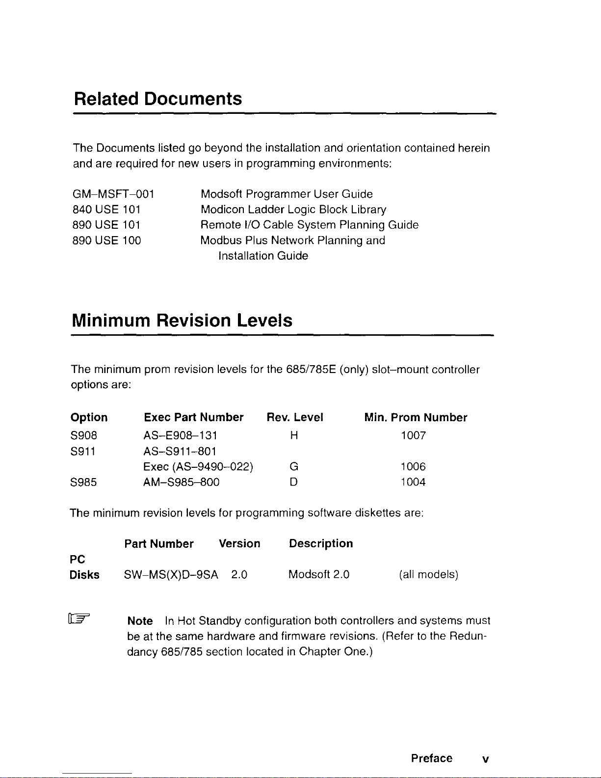
The minimum prom revision levels for the 685/785E (only) slot-mount controller
options are:
Option
S908
s911
5985
Exec Part Number
Rev. Level Min. Prom Number
AS-E9081 31
H
1007
AS-S91 l-801
Exec (AS-9490-022)
G 1006
AM-S985800
D
1004
The minimum revision levels for programming software diskettes are:
PC
Disks
Part Number
Version
Description
SW-MS(X)D-9SA 2.0
Modsoft 2.0 (all models)
CR
Note
In Hot Standby configuration both controllers and systems must
be at the same hardware and firmware revisions. (Refer to the Redundancy 6851785 section located in Chapter One.)
Preface v
Page 8
Incoming Inspection Guidelines
Guidelines for Inspection
o Before you do anything, verify your shipment is complete and undamaged. If
the shipment is incomplete or damaged, notify the carrier and your distributor.
o Remove everything from its packing and check for physical defects or damage.
If the equipment is physically defective or damaged, notify your Modicon representative.
ID=
Note
Save shipping materials until installation is complete.
Sending Something Back?
o Whenever possible, use the original packing materials supplied by Modicon.
o All equipment should be firmly packed so that it cannot move around in its ship-
ping container.
o All equipment should be protected against impact during shipment.
IJ All equipment should be clearly marked with its Return Authorization Number
@A#).
vi Preface
Page 9
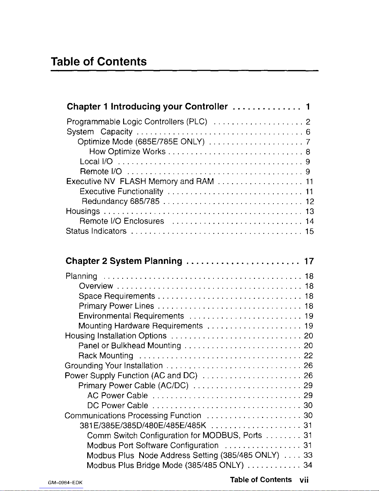
Table of Contents
Chapter 1 Introducing your Controller
. . . a
Programmable Logic Controllers (PLC) .
System Capacity . . . . . . . . . . . . .
. .
Optimize Mode (685E/785E ONLY) . . .
How Optimize Works . . . . . . . .
. .
Local
I/O
. . . . . . . . . . . . . . . . . . . . . . .
. .
Remote I/O . . . . . . . . . . . . . . . .
Executive NV FLASH Memory and RAM
. . .
Executive Functionality . . . . . . . .
. . .
Redundancy685785 . . . . . . . . . . . . .
Housings . . . . . . . . . . . . . . . . . . . . . . . . . .
. .
Remote I/O Enclosures
. . . . . . .
. . .
Status Indicators . . . . . . . . . . .
. . . .
.........
.........
.........
.........
.........
.........
.........
.........
.........
.........
.........
1
2
6
7
8
9
9
11
11
12
13
14
15
Chapter 2 System Planning
. . . . . . . . . . . . L , _ . . . . . . . .
17
Planning . . . . . . . . . . . . . .
Overview . . . . . . . . . . .
Space Requirements . . . . . . .
Primary Power Lines . . . . . . . . .
Environmental Requirements . . . .
Mounting Hardware Requirements .
Housing Installation Options . . . . .
Panel or Bulkhead Mounting . .
Rack Mounting . . . . . . . . . . .
Grounding Your Installation . . . . . . . .
Power Supply Function (AC and DC) .
Primary Power Cable (AC/DC) . .
AC Power Cable . . . . . .
DC Power Cable . . . . . . . . . . .
Communications Processing Function .
381 E/385E/385D/480E/485E/485K
......
...... 18
......
......
18
......
......
18
......
...... 18
......
...... 19
......
...... 19
......
...... 20
......
...... 20
......
...... 22
......
...... 26
......
...... 26
......
...... 29
......
...... 29
......
...... 30
......
...... 30
......
...... 31
Comm Switch Configuration for MODBUS, Ports
........
31
Modbus Port Software Configuration
.................
31
Modbus Plus Node Address Setting (385/485 ONLY)
.... 33
Modbus Plus Bridge Mode (385/485 ONLY)
............
34
Table of Contents vii
GM-0984-EDK
Page 10
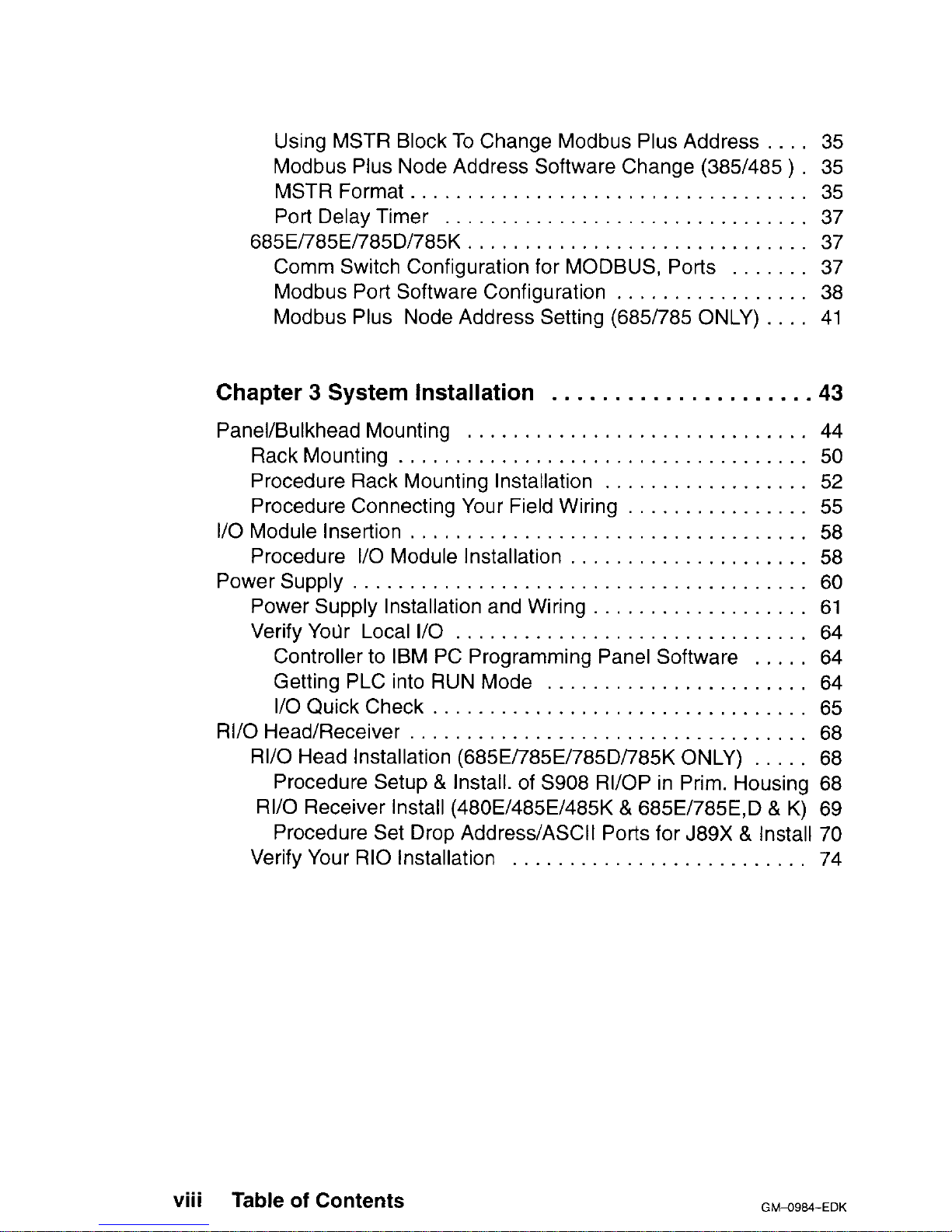
Using MSTR Block To Change Modbus Plus Address . . . 35
Modbus Plus Node Address Software Change (385/485 ) 35
MSTR Format . . . . . . . . . . . . . . . . . . . . . 35
Port Delay Timer . . . . . . . . . . . . 37
685El785El785DI785K . . . . . . . . . . . . . . . . . . . . . . . . . .
37
Comm Switch Configuration for MODBUS, Ports . 37
Modbus Port Software Configuration . . . . . . . . . . . . . . . .
38
Modbus Plus Node Address Setting (685i785 ONLY) . . .
41
Chapter 3 System Installation
.....................
43
Panel/Bulkhead Mounting ..............................
44
RackMounting ....................................
50
Procedure Rack Mounting Installation ..................
52
Procedure Connecting Your Field Wiring ................
55
I/O Module insertion
...................................
58
Procedure I/O Module Installation .....................
58
PowerSupply ........................................
60
Power Supply Installation and Wiring ...................
61
Verify Your Local I/O ...............................
64
Controller to IBM PC Programming Panel Software
..... 64
Getting PLC into RUN Mode .......................
64
I/OQuickCheck
................................. 65
RI/O Head/Receiver
...................................
68
RI/O Head Installation (685E/785E/785Di785K ONLY)
..... 68
Procedure Setup & Install. of S908 RI/OP in Prim. Housing 68
RI/O Receiver Install (480E/485E/485K & 685E/785E,D & K) 69
Procedure Set Drop Address/ASCII Ports for J89X & Install 70
Verify Your RIO Installation ..........................
74
. . .
VIII
Table of Contents
Page 11
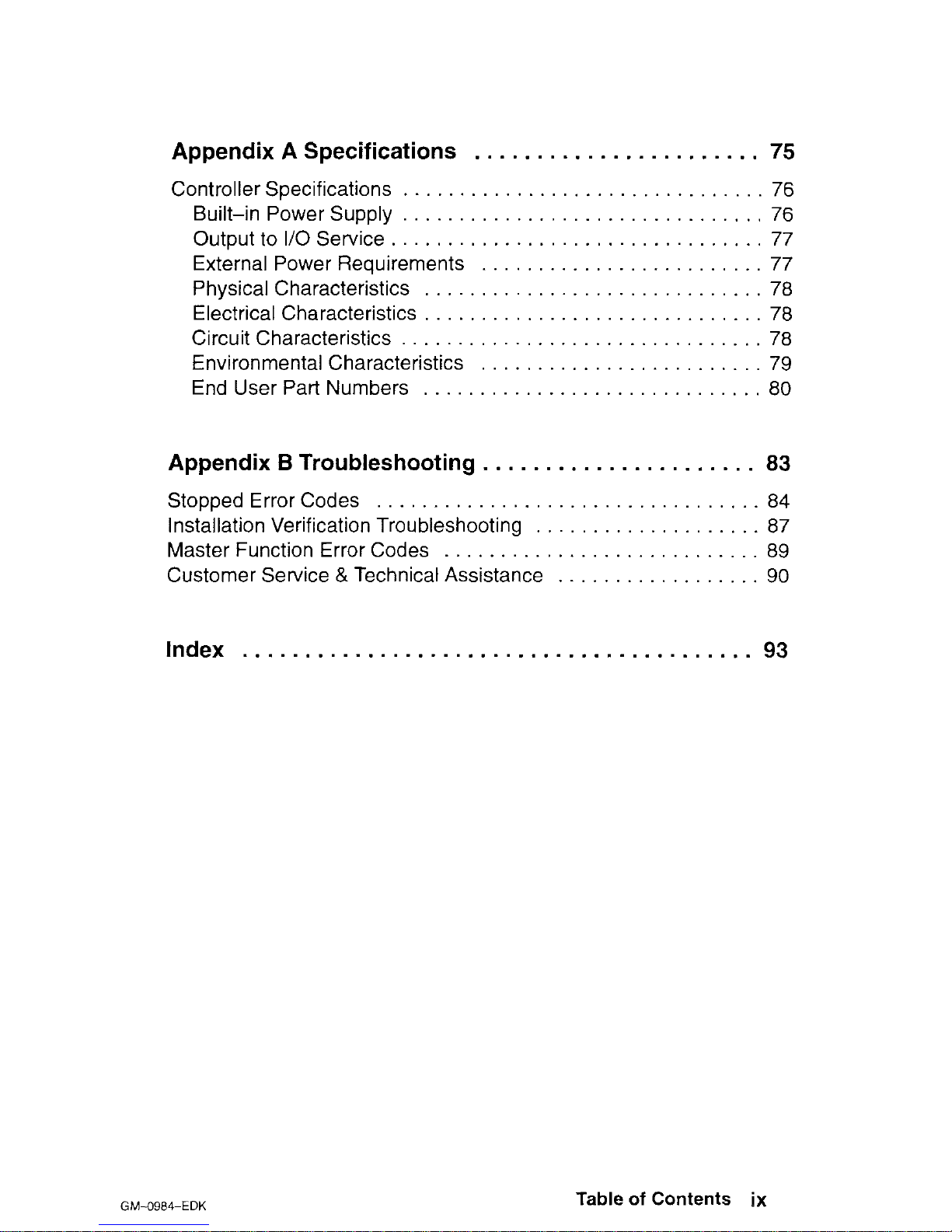
Appendix A Specifications
. . . . . . . . . . . . . . . . . . . . . . .
75
Controller Specifications . . . .
Built-in Power Supply . . .
Output to I/O Service . . . .
External Power Requirements
Physical Characteristics . . .
Electrical Characteristics . . .
Circuit Characteristics . . . .
Environmental Characteristics
End User Part Numbers . . .
. . .
......
76
. . ......
76
. . .
......
77
. . . . .
......
77
. . . .
......
78
. . . .
......
78
. . .
......
78
. . . .
......
79
. . . .
......
80
Appendix B Troubleshooting
. . . . . . . . . . . . . . . . . . . . . .
83
Stopped Error Codes
. . . . . . . . . . . . .
........
. a4
Installation Verification Troubleshooting . .
........
. a7
Master Function Error Codes . . . . . . . . . . .
........
a9
Customer Service & Technical Assistance . .
........
. 90
Index
. . . . . . . . . . . . . . . . . . . . . . . . . . . . . . . . . . . . . . . . . 93
GM-O984-EDK
Table of Contents ix
Page 12
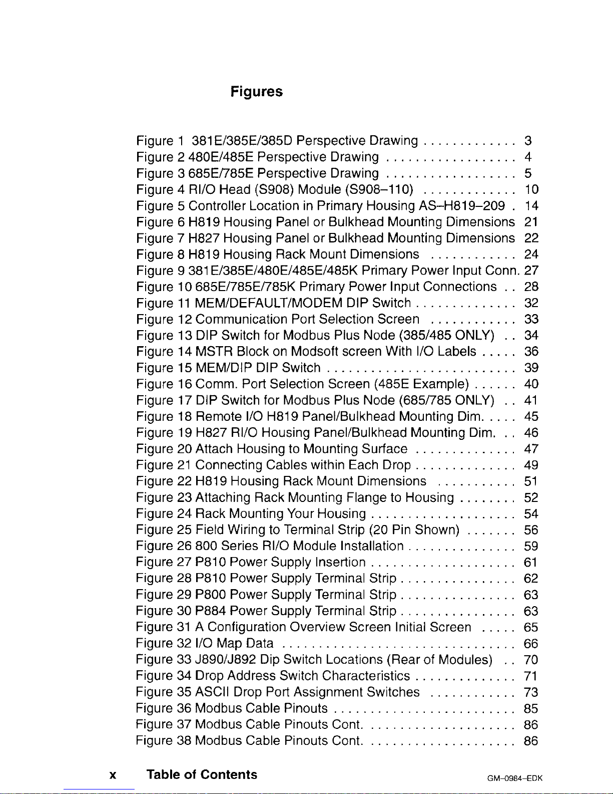
Figures
Figure 1 381 EI385El385D Perspective Drawing ............. 3
Figure 2 480E/485E Perspective Drawing .................. 4
Figure 3 685E/785E Perspective Drawing .................. 5
Figure 4 RI/O Head (S908) Module (S908-110) ............. 10
Figure 5 Controller Location in Primary Housing AS-H81 9-209 . 14
Figure 6 H819 Housing Panel or Bulkhead Mounting Dimensions 21
Figure 7 H827 Housing Panel or Bulkhead Mounting Dimensions 22
Figure 8 H819 Housing Rack Mount Dimensions ............ 24
Figure 9 381 E/385E/480E/485E/485K Primary Power Input Conn. 27
Figure 10 685E/785E/785K Primary Power Input Connections . . 28
Figure 11 MEM/DEFAULT/MODEM DIP Switch .............. 32
Figure 12 Communication Port Selection Screen ............ 33
Figure 13 DIP Switch for Modbus Plus Node (385/485 ONLY) . 34
Figure 14 MSTR Block on Modsoft screen With I/O Labels ..... 36
Figure
15
MEM/DIP DIP Switch
.......................... 39
Figure 16 Comm. Port Selection Screen (485E Example) ...... 40
Figure 17 DIP Switch for Modbus Plus Node (685/785 ONLY) . . 41
Figure 18 Remote I/O H819 Panel/Bulkhead Mounting Dim. .... 45
Figure 19 H827 RI/O Housing Panel/Bulkhead Mounting Dim. .. 46
Figure 20 Attach Housing to Mounting Surface .............. 47
Figure 21 Connecting Cables within Each Drop
.............. 49
Figure 22 H819 Housing Rack Mount Dimensions ........... 51
Figure 23 Attaching Rack Mounting Flange to Housing ........ 52
Figure 24 Rack Mounting Your Housing .................... 54
Figure 25 Field Wiring to Terminal Strip (20 Pin Shown) ....... 56
Figure 26 800 Series RI/O Module Installation
............... 59
Figure 27 P810 Power Supply Insertion .................... 61
Figure 28 P810 Power Supply Terminal Strip ................ 62
Figure 29 P800 Power Supply Terminal Strip ................ 63
Figure 30 P884 Power Supply Terminal Strip ................ 63
Figure 31 A Configuration Overview Screen Initial Screen ..... 65
Figure 32 I/O Map Data ................................ 66
Figure 33 J89O/J892 Dip Switch Locations (Rear of Modules) 70
Figure 34 Drop Address Switch Characteristics .............. 71
Figure 35 ASCII Drop Port Assignment Switches ............ 73
Figure 36 Modbus Cable Pinouts ......................... 85
Figure 37 Modbus Cable Pinouts Cont. .................... 86
Figure 38 Modbus Cable Pinouts Cont. .................... 86
X
Table of Contents
GMa984-EDK
Page 13
Figure 39 Controller Installation Troubleshooting Chart . . . . . . 87
Figure 40 Controller Installation Troubleshooting Chart (Sheet 2)
88
Tables
Table 1 Memory Per Configuration
...........
Table 2 Memory Per Configuration Cont.
......
Table 3 Communication Options per PLC
......
Table 4 Port 1 Configuration
................
Table 5 Port 1 Configuration
................
Table 6 Partial Modbus Plus Address Examples
Table 7 J89O/J892 Drop Address Switch Settings
Table 8 J892 ASCII Port Address Settings
.....
Table 9 End User Part Numbers
.............
Table 10 Stopped Error Codes
...............
Table
11
MSTR Error Code Definitions
.........
. . .
. . . .
. . .
. . .
. .
. . .
. .
. 6
. 7
. 30
. 31
38
. 42
72
. 73
. 80
. 84
. 89
GM-0984-EDK
Table of Contents xi
Page 14

Page 15
Chapter
1
Introducing your Controller
~3 Programmable Logic Controllers (PLC)
0 System Capacity
o Executive NV FLASH Memory and RAM
o Housings
o Status Indicators
GM-0984-EDK
Introducing your Controller
1
Page 16

Programmable Logic Controllers (PLC)
The Modicon 984-381 ~t3a5~t385Dt480~~4a5~t485bu685~~785~~785~~785u
Controllers are mid-range Programmable Logic Controllers in a modular, expandable, architecture. They employ Modicon 800 series housings, interfaces and I/O
modules. These PLC’s are supported by the same instruction set as the other 984
models, and are programmed by Modsoft panel software. All of these units have a
built-in power supply. All of these units are fully compatible with the Modicon 984
PC instruction set, and solve user logic at a rate of from 1 ms to 2.5 ms per thousand nodes of user logic. The 785El785Dl785K are 24-bit CPU’s and the rest are
16-bit CPU’s.
These units have two, or three built-in Modbus ports for data transfer and remote
programming. Through these ports, communication processing on the CPU board
links the controller to multiple supervisory and programming devices such as a
host computer or Modicon’s programming panel. The two Modbus ports allow you
to connect more than one Modbus device to the controller. Some models have
both a single Modbus port and a second port for the Modbus Plus high speed Local Area Network. While others have two Modbus ports and one Modbus Plus
port. The DIP switch for setting the Modbus Plus port address can be accessed
through the bottom of the module’s case.
User memory is backed up by a lithium battery which has a conservatively rated
service life of one year. Once energized, the BATTERY LOW indicator will come
ON when the battery has 14 days left before it will be effectively drawn down. The
battery has a five-year shelf life.
w
Note
The 485K and 785K are the same has the 485E and 785E ex-
cept the K’s have a memory protect Key Switch on the front of the unit.
w
Note
The 385D and 785D are the same has the 385E and 785E ex-
cept the D’s operate on 125VDC rather than 115/23OVAC.
Figure 1 is a perspective view of the 381 E/385E/385D controllers. Certain physical features are noted.
2
Introducing your Controller
GWO984-EDK
Page 17
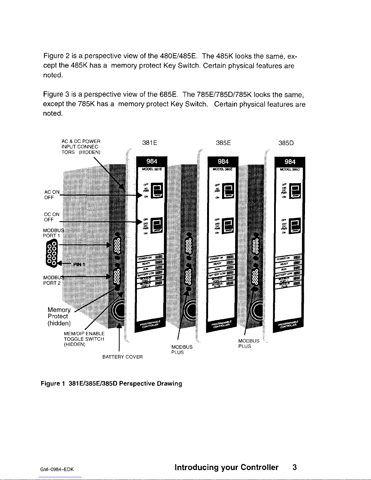
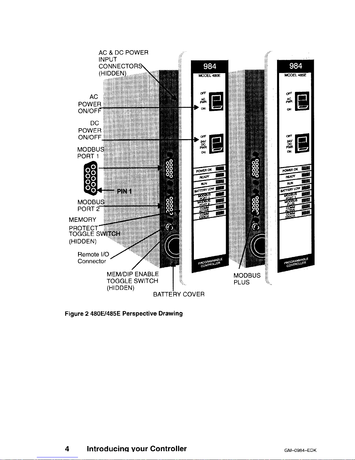
Figure 2 is a perspective view of the 480E/485E. The 485K looks the same, except the 485K has a memory protect Key Switch. Certain physical features are
noted.
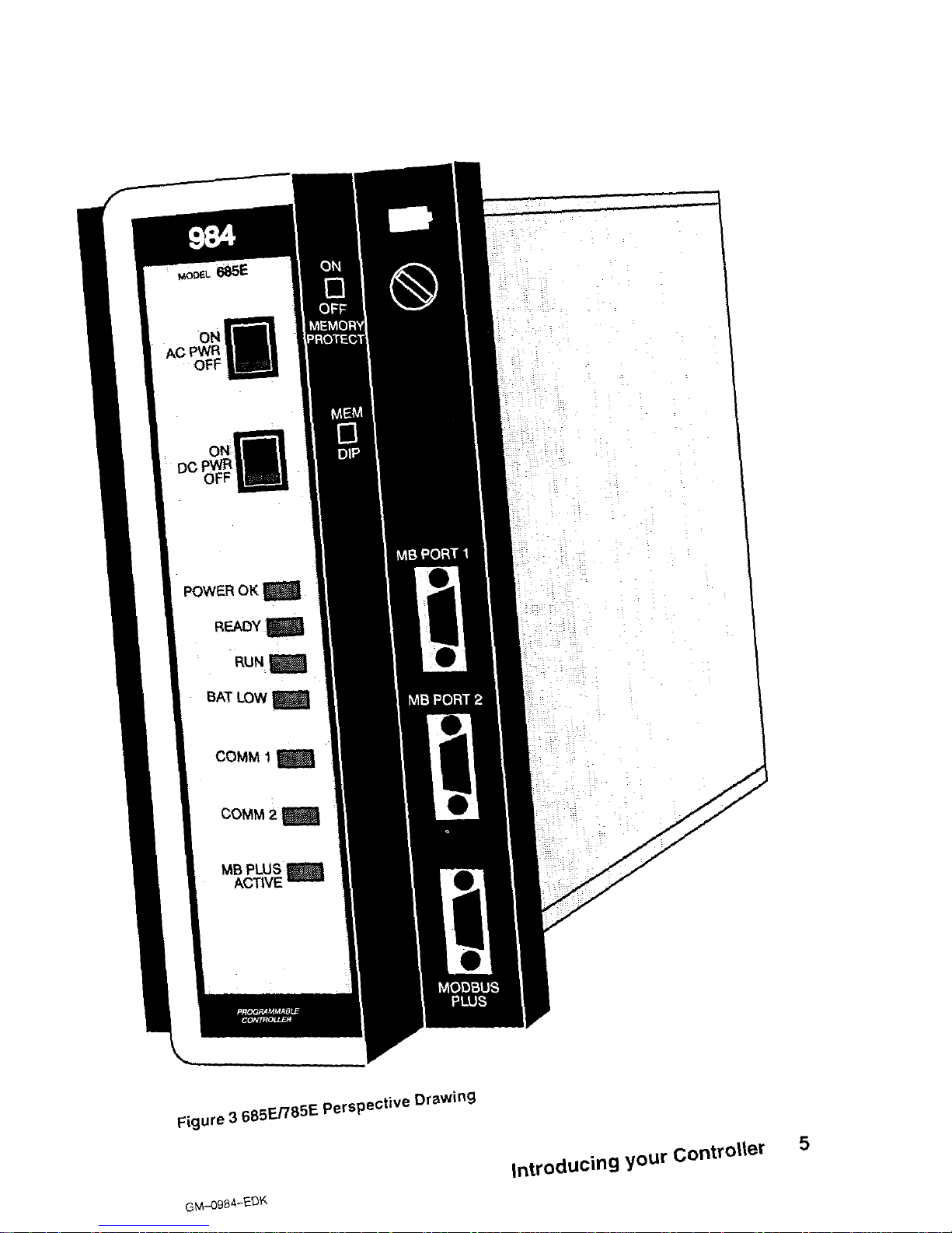
Figure 3 is a perspective view of the 685E. The 785E/785D/785K looks the same,
except the 785K has a memory protect Key Switch.
Certain physical features are
noted.
AC & DC POWER
INPUT CONNEC-
381 E 385E
TORS (HIDDEN)
TOGGLE SWITCH
I’
(HIDDEN)
BATTERY COVER
I
MODBUS
PLUS
Figure 1 381E/385E/385D Perspective Drawing
MODBUS
PLUS
GM-0984-EDK
Introducing your Controller
3
Page 18
AC 8, DC POWER
INPUT
CONNECTORS\
AC
POWER
ON/OFF
PORT 1
,“,LI.l_l . I
PROTECT-
TOGGI F .S\
Connects
MEM/DIP ENABLE ;
I
TOGGLE SWITCH ‘.
--
MODBUS
PLUS
(HIDDEN)
I
BATTERY COVER
Figure 2 4800485E Perspective Drawing
4 Introducing your Controller
GMXCF34-EDK
Page 19
AC P’%
OFF
POWER OK
READY
RUN
BAT LOW
COMM
1
COMM 2
Figure 3 685En85E Perspective Drawing
GM-0984-EDK
Introducing your Controller
5
Page 20
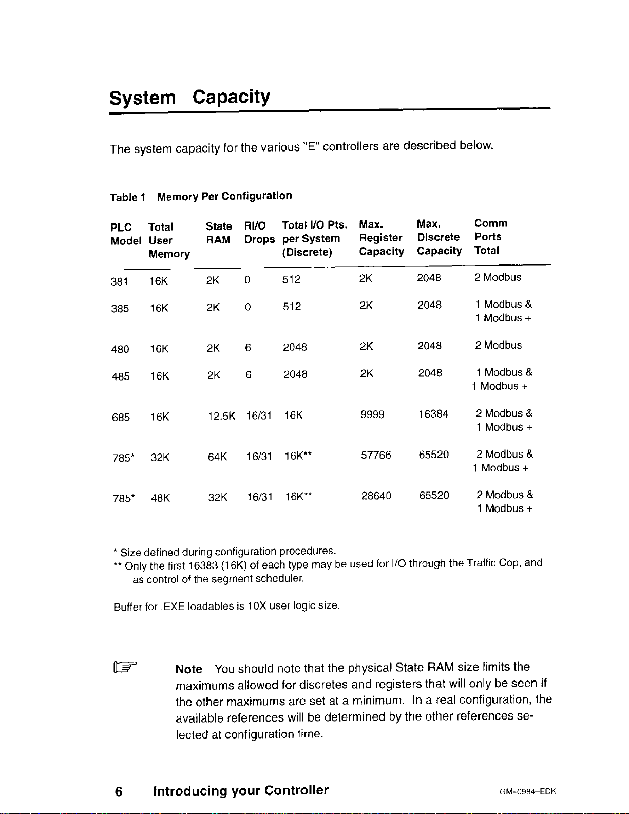
System Capacity
The system capacity for the various “E” controllers are described below.
Table 1 Memory Per Configuration
PLC
Total
State RI/O Total I/O Pts. Max.
Max. Comm
Model User
RAM Drops per System
Register Discrete Ports
Memory
(Discrete)
Capacity Capacity Total
381 16K 2K 0 512
2K 2048 2 Modbus
385 16K 2K 0 512
2K 2048 1 Modbus &
1 Modbus +
480 16K 2K 6 2048
2K 2048 2 Modbus
485 16K 2K 6 2048
2K 2048 1 Modbus &
1 Modbus +
685 16K 12.5K 16/31 16K
9999 16384 2 Modbus &
1 Modbus +
785* 32K 64K 16/31 16K”
57766 65520 2 Modbus &
1 Modbus +
785* 48K 32K 16131 16K**
28640 65520 2 Modbus &
1 Modbus +
* Size defined during configuration procedures.
‘* Only the first 16383 (16K) of each type may be used for I/O through the Traffic Cop, and
as control of the segment scheduler.
Buffer for .EXE loadables is 10X user logic size.
6
Introducing your Controller
Note You
should note that the physical State RAM size limits the
maximums allowed for discretes and registers that will only be seen if
the other maximums are set at a minimum. In a real configuration, the
available references will be determined by the other references selected at configuration time.
GM-O984-EDK
Page 21
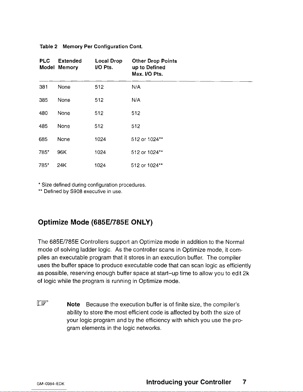
Table 2 Memory Per Configuration Cont.
PLC Extended
Model Memory
Local Drop Other Drop Points
l/o Pts. up to Defined
Max. l/O Pts.
381 None
512
N/A
385
None
512 N/A
480
None 512 512
485 None 512 512
685 None 1024 512 or 1024”
785* 96K
1024 512 or 1024”
785* 24K 1024 512 or 7024*’
* Size defined during configuration procedures.
** Defined by S908 executive in use.
Optimize Mode (685E/785E ONLY)
The 685EI785E Controllers support an Optimize mode in addition to the Normal
mode of solving ladder logic. As the controller scans in Optimize mode, it compiles an executable program that it stores in an execution buffer. The compiler
uses the buffer space to produce executable code that can scan logic as efficiently
as possible, reserving enough buffer space at start-up time to allow you to edit 2k
of logic while the program is running in Optimize mode.
w
Note
Because the execution buffer is of finite size, the compiler’s
ability to store the most efficient code is affected by both the size of
your logic program and by the efficiency with which you use the program elements in the logic networks.
GMa984-EDK
Introducing your Controller
7
Page 22
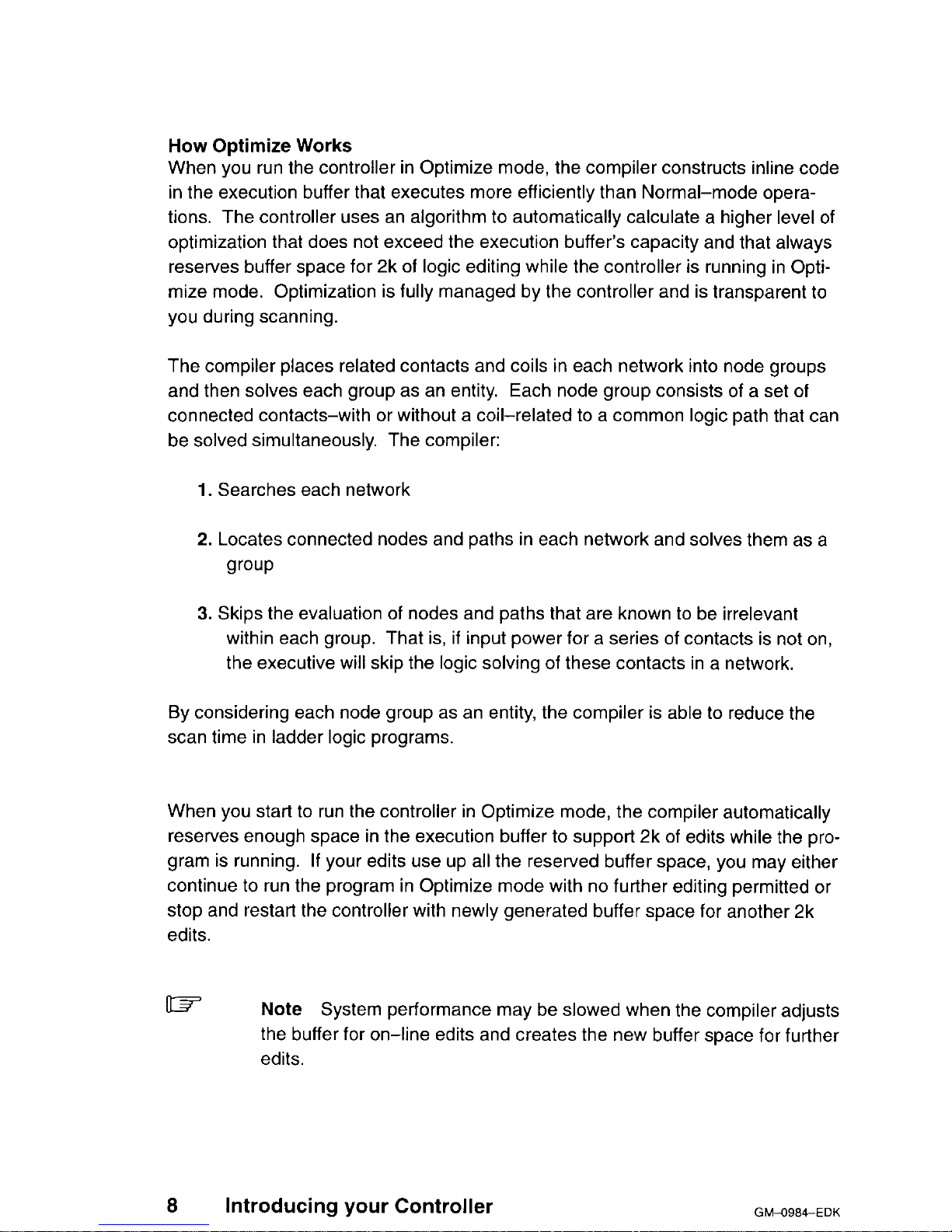
How Optimize Works
When you run the controller in Optimize mode, the compiler constructs inline code
in the execution buffer that executes more efficiently than Normal-mode operations. The controller uses an algorithm to automatically calculate a higher level of
optimization that does not exceed the execution buffer’s capacity and that always
reserves buffer space for 2k of logic editing while the controller is running in Optimize mode. Optimization is fully managed by the controller and is transparent to
you during scanning.
The compiler places related contacts and coils in each network into node groups
and then solves each group as an entity.
Each node group consists of a set of
connected contacts-with or without a coil-related to a common logic path that can
be solved simultaneously. The compiler:
1. Searches each network
2. Locates connected nodes and paths in each network and solves them as a
group
3. Skips the evaluation of nodes and paths that are known to be irrelevant
within each group. That is, if input power for a series of contacts is not on,
the executive will skip the logic solving of these contacts in a network.
By considering each node group as an entity, the compiler is able to reduce the
scan time in ladder logic programs.
When you start to run the controller in Optimize mode, the compiler automatically
reserves enough space in the execution buffer to support 2k of edits while the program is running. If your edits use up all the reserved buffer space, you may either
continue to run the program in Optimize mode with no further editing permitted or
stop and restart the controller with newly generated buffer space for another 2k
edits.
03
Note System performance may be slowed when the compiler adjusts
the buffer for on-line edits and creates the new buffer space for further
edits.
8
Introducing your Controller
GM0984-EDK
Page 23
Local I/O
All of the Controllers support one local I/O drop in the form of Modicon 800 series
module housings. Local I/O processing is always Drop #I Total Local I/O pro-
vides for Discrete points configured in any mix and registers, refer to Table 1 for
memory configuration for each individual Controller.
Remote I/O
The 480E/485E/485K Controllers have up to 6 drops (one local and five remote)
for a total I/O support capacity of 1024 discrete I/O points (any mix). The
480E/485E/485K also support up to 5 RI/O drops (using the built-in S908 Remote
I/O Processor and optional J89O/P890 RI/O Adapters) with a maximum of 512
more discrete I/O points on one drop or spread over them all. Also, the
480E/485E/485K support a maximum of 2 ASCII ports per drop, up to a total maximum of 12 using optional J892YP892 RI/O ASCII Adapters. Please refer to
GM-0984RIO Modicon Remote l/O Cable System Planning Guide for more details.
The 685El785El785DI785K require a separate RI/O Head module with a plug-in
executive cartridge capable of supporting either 16/31 RI/O drops. The 16 RI/O
drops (using the Executive Cartridge AS-Ego&01 6 on the S908) have
1 Kin/l Kout (I/O bits). It can also support 31 RI/O drops (using the Executive Car-
tridge AS-E908-131 on the S908) with each drop having a maximum of
512in/512out (I/O bits). While the total I/O capacity is 65536 bits, only the first 16K
can be I/O mapped regardless of which S908 executive cartridge is used, (local Ii
0 bits maximum is 1 Kin/l Kout). The S908 Remote I/O Processor comes in two
versions: a single cable (AS-S908-ll O), or dual cable (AS-S908-120). Please
refer to GM-0984RIO Modicon Remote I/O Cable System Planning Guide.
These controllers also support a maximum of 2 ASCII ports per drop up to a total
maximum of 32 using optional J892/P892 RI/O ASCII Adapters. Please refer to
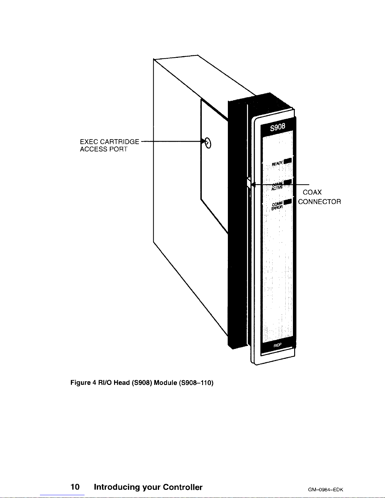
GM-0984-RIO Modicon Remote I/O Cable System Planning Guide for more details. Figure 4 is a perspective view of the RIOP module.
The RI/O interface will drive RI/O up to 5000 feet away (this distance can be increased depending upon the cable selection and certain other customer application considerations). Since the 5000 foot distance allows wide latitudes in system
layout and installation, substantial economies can be realized from carefully
planned layouts. Another planning requirement is to keep attenuation losses within
the system’s 35 dB dynamic range.
GM-0984-EDK
introducing your Controller 9
Page 24
EXEC CARTRIDGE -
ACCESS PORT
10
Introducing your Controller
COAX
CONNECTOR
Figure 4 RI/O Head (S908) Module (S908-110)
GM-O984-EDK
Page 25
Executive NV FLASH Memory and RAM
The PLC’s feature executive firmware as two levels of memory which are referred
to in this manual as executive and user memory. The executive is contained in
Non-Volatile flash memory that can be upreved in the field if required, and the
user memory is stored in battery backed RAM. (Refer to the Customer Service &
Technical Assistance section located in Appendix B regarding upgrading NV
FLASH Memory in the field.)
A controller bootable memory software is downloaded to a protected area of flash
memory during the manufacturing process which is not accessible to the user.
Executive Functionality
381
Executive ID of 813 (Hex), CPU Clock speed 12 Mhz.
24 DX functions:
MOVE (8), MATRIX (8), JSR, RET, LAB, PID2, EMTH, TBLK, BLKT, and
CKSM.
Two standard Modbus ports, Time-of-Day clock, Local l/O only.
385
Executive ID of 81 E (Hex), CPU Clock speed 12 Mhz.
24 DX functions:
MOVE (8), MATRIX (8), JSR, RET, LAB, PID2, EMTH, TBLK, BLKT and
MSTR.
(MSTR is the user interface to Modbus Plus. It replaces the CKSM function
and uses its opcode.
One Modbus port, One Modbus Plus Port, Time-of-Day clock, Peer Cop,
Local I/O only.
480
Executive ID of 822 (Hex), CPU Clock speed 12 Mhz.
26 DX functions:
MOVE (8), MATRIX (8), JSR, RET, LAB, PID2, EMTH, TBLK, BLKT, READ,
WRIT and CKSM.
Two standard Modbus ports, Time-of-Day clock, Remote I/O.
GM-0984-EDK
Introducing your Controller
11
Page 26
o 485
Executive ID of 82E (Hex), CPU Clock speed 12 Mhz.
26 DX functions:
MOVE (8) MATRIX (8) JSR, RET, LAB, PID2, EMTH, TBLK, BLKT READ,
WRIT and MSTR.
(MSTR is the user interface to Modbus Plus. It replaces the CKSM function
and uses the CKSM opcode.
One Modbus port, One Modbus Plus Port, Time-of-Day clock, Peer Cop,
Remote I/O.
IJ 685
Executive ID of 80C (Hex), CPU Clock speed 16 Mhz.
39 DX functions:
MOVE (8) MATRIX (8) JSR, RET, LAB, PID2, EMTH, TBLK, BLKT,
CKSM, 16 BIT MATH (7), PCFL (18), and MSTR.
Two standard Modbus ports, One Modbus Pius Port, Time-of-Day clock,
Peer Cop, Remote I/O (via S908 module).
o 785
Executive ID of 852 (Hex), CPU Clock speed 16 Mhz.
39 DX functions:
MOVE (8), MATRIX (8) JSR, RET, LAB, PID2, EMTH, TBLK, BLKT,
CKSM, 16 BIT MATH (7), PCFL (18) and MSTR.
Two standard Modbus ports, One Modbus Plus Port, Time-of-Day clock,
Peer Cop, Remote I/O (via S908 module).
UT
Note
Both the MSTR and CKSM may coexist in the
685E/785E.
Redundancy 685/785
o At minimum these items are needed to support redundancy:
HSBY Loadable Software, Q 2 Rev 2.0
Hot Standby Adapter, S91 I-801
Remote I/O Adapter, S908 8 1 Rev 1007
12
Introducing your Controller
GM+984-EDK
Page 27
IB
Note
For the 685E/785E only, the first 10K of registers, and the first
8192 inputs and 8192 coils, are transfered on a switchover.
Housings
The PLC’s systems use Modicon 800 series housings for its controller and l/O
modules; specifically, a 19” primary housing which holds seven modules or a 27”
primary housing which holds eleven modules.
Primary Enclosure - With the single-width controllers mounted in your primary enclosure, the 19’ and 27” primary enclosures will hold up to 6 or 10 I/O modules respectively.
Secondary Enclosure-The remaining secondary housing will accommodate a
one and one-half wide P810, P800 or P884 auxiliary power supply if a power supply expander is required. That is, the standard 19” or 27” secondary housings will
accommodate five or nine I/O modules along with a one and one-half wide (twoslot) auxiliary power supply and a full seven or eleven I/O modules without the
power supply.
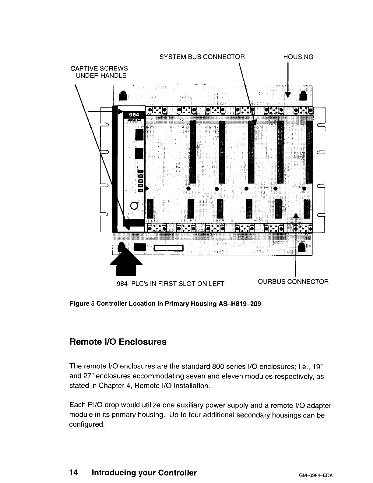
The 19-inch primary housing with controller is shown in Figure 5. For simplicity’s
sake, the 27” housing is not shown in this manual except as required in the
illustrations for panel mounting dimensions.
GM-O984-EDK
Introducing your Controller
13
Page 28
SYSTEM BUS CONNECTOR HOUSING
CAPTIVE SCREWS
UNDER HANDLE
\
I
984-PLC’s IN FIRST SLOT ON LEFT
OURBUS CONNECTOR
Figure 5 Controller Location in Primary Housing AS-H819-209
Remote I/O Enclosures
The remote I/O enclosures are the standard 800 series I/O enclosures; i.e., 19”
and 27” enclosures accommodating seven and eleven modules respectively, as
stated in Chapter 4, Remote I/O Installation.
Each RI/O drop would utilize one auxiliary power supply and a remote I/O adapter
module in its primary housing. Up to four additional secondary housings can be
configured.
14
Introducing
your Controller
GWO984-EDK
Page 29
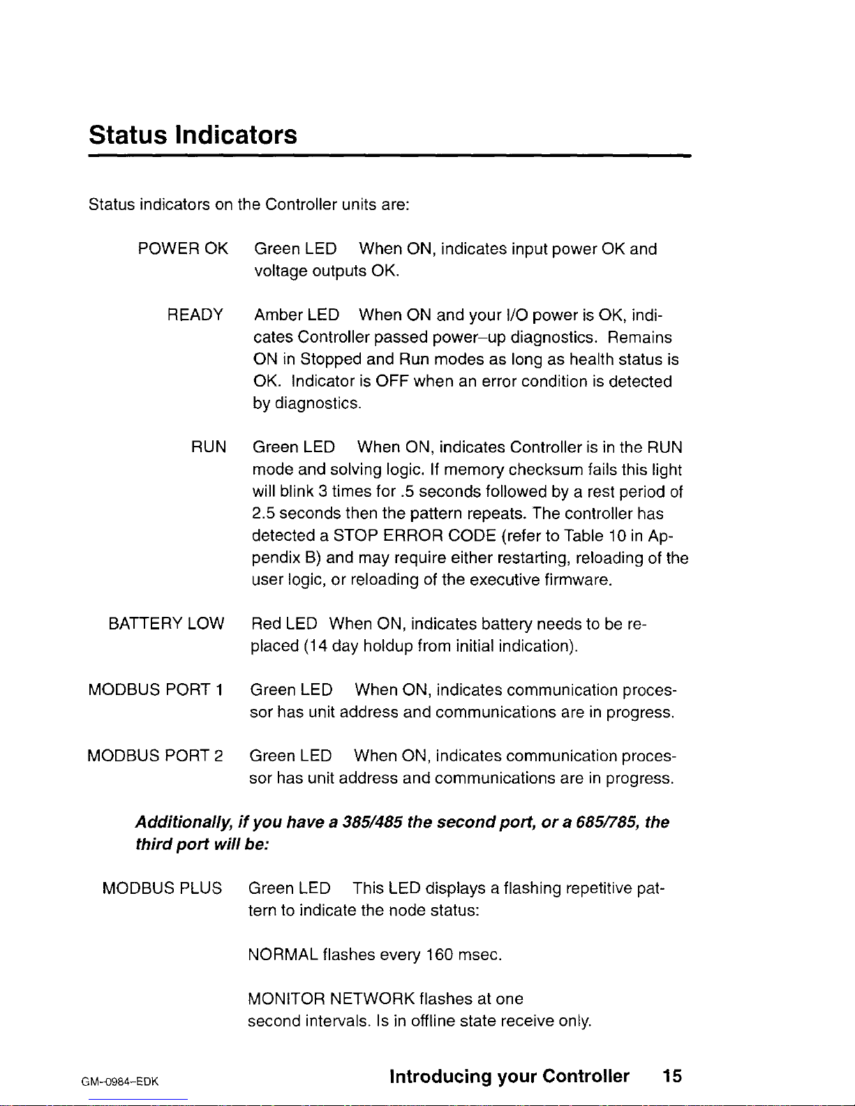
Status Indicators
Status indicators on the Controller units are:
POWER OK
READY
RUN
BATTERY LOW
MODBUS PORT 1
MODBUS PORT 2
Green LED When ON, indicates input power OK and
voltage outputs OK.
Amber LED When ON and your I/O power is OK, indicates Controller passed power-up diagnostics. Remains
ON in Stopped and Run modes as long as health status is
OK. Indicator is OFF when an error condition is detected
by diagnostics.
Green LED When ON, indicates Controller is in the RUN
mode and solving logic. If memory checksum fails this light
will blink 3 times for .5 seconds followed by a rest period of
2.5 seconds then the pattern repeats. The controller has
detected a STOP ERROR CODE (refer to Table IO in Appendix B) and may require either restarting, reloading of the
user logic, or reloading of the executive firmware.
Red LED When ON, indicates battery needs to be re-
placed (14 day holdup from initial indication).
Green LED When ON, indicates communication processor has unit address and communications are in progress.
Green LED When ON, indicates communication processor has unit address and communications are in progress.
Additionally, if you have a 3851485 the second port, or a 6851785, the
third port will be:
MODBUS PLUS Green LED This LED displays a flashing repetitive pat-
tern to indicate the node status:
NORMAL flashes every 160 msec.
MONITOR NETWORK flashes at one
second intervals. Is in offline state receive only.
GM-0984-EDK
Introducing your Controller 15
Page 30

NOT RECEIVING TOKEN flashes two times then is off for
two seconds.
SOLE STATION flashes three times then is off for 1.7 seconds.
DUPLICATE NODE ADDRESS flashes four times then is
off for 1.4 seconds.
With a 480/485 you have two additional indicators:
COMM ACTIVE Green LED
When ON, indicates Remote I/O communica-
tion is in progress.
COMM ERROR
Red LED When ON, indicates a Remote I/O comm error
detected (example: CRC framing or missing physical drop)
16
Introducing your Controller
GM-O984-EDK
Page 31

Chapter 2
System Planning
0 Planning
o Housing Installation Options
o Grounding
o Power Supply Function (AC and DC)
o Communications Processing Function
GM-0984-EDK
System Planning
17
Page 32

Planning
Overview
The PLC’s are designed to work with your Modicon Programming panel software;
Modicon 800 series housings, interfaces and I/O modules.
The site planner must also consider the peripheral equipment (such as a Programmer, CRT monitor, or printer) when preparing an installation plan for the site. Refer to the appropriate Modicon publications for site preparation procedures for related equipment.
Space Requirements
For the primary housing, allow 12 inch clearance to the left so installer can see
power supply connectors. Allow 6 inches on the top and side of the housing for
convection cooling in vertical mounting situations. Allow 12 inch of clearance at
the bottom of the Controller for cable access.
For all other housings, allow 6 inches on the top and sides of each housing for unobstructed cooling airflow in vertical mounting situations.
Also consider installation and physical access for removal of the modules as well
as subsequent set-vice including the connection and detachment of signal and
power cables when required.
The primary housing may be separated up to 12 feet from the secondary housing.
Primary Power Lines
In addition to service access, distance to power sources has to be considered in
planning your controller installation. In addition to cable routing considerations,
good practices dictate that the power lines be dedicated to the Controller installation to minimize problems that sometimes arise when sharing AC power with electrically noisy equipment.
18 System Planning
GhMSS4-EDK
Page 33

Finally, plan to install a service loop and a cable restraint as the primary power
cable connector is not locked in place.
Environmental Requirements
In planning for the PI-C’s installation, consideration should be given to the environ-
ment around the controller. Although designed for a harsh industrial environment
and able to withstand factors that would harm other types of electronic equipment,
problems can be avoided by not placing the controller and its related equipment in
an operating area where there is high ambient temperature, acidic atmosphere, vibration, dust, and dirt if it can be avoided.
Mounting Hardware Requirements
After deciding on the final location of the Controller, its associated equipment and
cables, you should plan for related mounting hardware. This would include such
items as: nut and bolt combinations, flat and star washers, housings, mounting
surface, ground straps and system ground connections,
Mounting bolts are NOT provided. The recommended mounting bolts are
0.312-24 UNF-2B (insert or tapped) stainless steel (#8-13-SS).
GM-O984-EDK
System Planning 19
Page 34

Housing Installation Options
The PLC’s system housing can be panel/bulkhead mounted or rack mounted as
described in the following text.
Panel or Bulkhead Mounting
As shown in Figure 6 and Figure 7 below, the housing has keyholes at the top and
bottom of the housing for bulkhead mounting purposes. The keyholes are sized
for 5/l 6-inch bolts. The recommended ground point is also shown.
20
System Planning
Gb!-O984-EDK
Page 35

225.3
(8.87)
I
lndl’ T
342.9
(135)
7
f
ii!4
”
0
1
G-ROUND POINT
Figure 6 H819 Housing Panel or Bulkhead Mounting Dimensions
GM49846EDK
System Planning 21
Page 36

(“izz
(165iy
f
303.3
(11.941
1
687.7
(27.08)
645.2
(25.40) d
I
1
1 cl
-
-
-
-
-
I
GROUND POINT
Figure 7 Ha27 Housing Panel or Bulkhead Mounting Dimensions
T
225.3
(8.87)
10.4
(.41)
f
‘t
342.9
(13.50)
1
22
System Planning
GM-O984-EDK
Page 37

Rack Mounting
The H819 Module Housings can be mounted in a 1 C&inch standard (EIA) rack.
Optional hardware can be supplied for installing the “rack adaptor - mounting
flange kit”.
Figure 8 shows dimensions for rack mounting RI/O housing. The following hardware is required for rack mounting each housing:
o (1) 19-inch Standard (EIA) rack
CI (1) pair of rack mounting flanges
o (8) #lo-32, Pan Head Machine Screws to mount the housing to the NEMA rack
o (8) #I O-32 Flat Lock Nuts if mounting holes in rack’s side rails rails are not
threaded.
o (8) #8-32 Pan Head Machine Screws (supplied) to attach rack mount flanges to
ends of housing
o (8) l/4 bolts (supplied) to attach back of rack mount flanges back of housing
GM-O984-EDK
System Planning 23
Page 38

203
(7.99)
1!30.;~
(7.50)
+
234
(9.22)
381 E
S908 &ROUND POINT
Figure 8 H819 Housing Rack Mount Dimensions
Some planning considerations common to rack mounting for 800 series I/O
housings are:
24
System Planning
GM-O984-EDK
Page 39

1
Between housings, allow 12 inches below the primary
housing for cable breakout, physical inspection and ventila-
tion.
2 The cable length connecting the primary housing and sec-
ondary housing must not exceed 12 feet.
The modular chassis will fit in a 12-inch deep standard NEMA enclosure should
this be required (e.g., an acidic atmosphere in the factory).
07
Note
The only cooling available to the PLC’s is derived from natural
convection air flow. If the Controller is placed within a NEMA enclosure, some provision for added cooling may be required. The controllers should also be mounted vertically to ensure adequate convection
cooling of internal components.
GM4984-EDK
System Planning 25
Page 40

Grounding Your Installation
For grounding purposes, your PLC housing(s) should be mounted on a suitably
finished metal mounting plate capable of supporting its weight along with the other
modules in the installation. An aluminum mounting plate with a chromate finish
such as IRIDITE, ALODINE or OAKITE No.36 would provide a low frequency (AC)
safety ground path and a low impedance shield path for EMI/RFI.
If a metal mounting plate (the preferred method) is not feasible, all PLC housings
within each drop should be interconnected by a flat braided ground strap with a
minimum width of 1 inch. The ground strap should be short and installed without
loops and bends. Use stainless steel hardware including a flat washer to secure
the braid strap to the housing.
Regardless of the housing-to-housing method of ground interconnection, the entire installation should be grounded by a 1” wide (min) flat, braided cable installed
between the the primary housing ground connection point and a suitable factory
ground. This ground strap should also be short and installed without loops and
bends. The bulkhead and rack mounting illustrations show the housing’s recommended grounding point.
Power Supply Function (AC and DC)
The PLC’s come with a built-in power supply.
The 381 El385El480E/485E/485K
Controllers run on 97 through 276 VAC (47 to 63 Hertz) and 24Vdc. As shown on
Figure 9, Once connected, AC power is then switched ON/OFF with a front panel
rocker switch.
The PLC will also operate continuously on 24Vdc as its an alternate or exclusive
source. Figure 9 shows a primary power input connector for a customer supplied
24Vdc source. Once connected, DC power is then switched ON/OFF with a front
panel rocker switch.
26
System Planning
GM+3984-EDK
Page 41

r------
----
-‘-------1
AC POWER IN
1
I
AC
POWER 1
FWITCH
2
(BLACK) HOT
I
,
- (WHITE)
NEUT
,
- (GREEN) GND 1
I
DC POWER
I
SWITCH
AREA OF DETAlLj
_-_----
Figure 9 381 E/385E/480E/485E/485K Primary Power Input Conn.
As shown in Figure 10, the 685El785El785K runs on 115 or 230VAC (47 to 63H.z)
and/or 24VDC. The AC input, primary power variable is selected by means of a
customer installed jumper. The primary power input connector is located at the
front left side of the unit and shown on the drawing as “115V operation jumper”.
Once connected, AC or DC POWER is switched ON/OFF with a front panel rocker
switch.
GM-G984-EDK
System Planning
27
Page 42

I-
------------_-------___~
i
AC PQWER IN
AC POWER
SWITCH
/
(WHITE) NEUT
- (BLACK) HOT
- (GREEN) GND
7
11%
JUMPER
230V
OPERATIOF
+ WITHOUT
JUMPER
/
SWITCH
DC
POWER ,
--I-
I
DC POWER IN ,
-I
i
AREA OF DETAIL,
-----__
E984
CONTROLLER
Figure 10 685E/785E/785K Primary Power Input Connections
The 385D/785D input can range from 105 to 150 VDC with the nominal at 125
VDC controlled by a front panel rocker switch. The 24 VDC option is also available. The 385D I/O capacity is 18.75W maximum using 3.5Amps, while the 785D
I/O capacity is 60W maximum using 7 Amps.
28
System Planning
GM+3984-EDK
Page 43

Note
The primary power AC/DC input feature was not designed, nor
is it suitable as an automatic battery backup provision in the event of
an AC/DC outage. This is because the controller’s externally sourced
input joins with the, internally produced DC. At any given time, the
Controller is taking from the higher of the two voltage sources if there
is as little as a 1V differential. The consequence of this would be to
draw down the DC battery if there were an extended period(s) of reduced AC/DC voltage supply.
If you want a backup alternative, one could be configured from a user-supplied
DC power supply with its own backup battery and charger combination along with
appropriate monitoring provisions.
Primary Power Cable (AC/DC)
Ideally, the input AC/DC power lines should be dedicated to the PLC installation to
minimize problems that arise when sharing AC power with electrically “noisy’
equipment.
Provide for strain relief by installing a service loop and cable restraint on the primary power cable as its connector is not locked in place.
AC Power
Cable
The recommended AC power cable should consist of three insulated leads of
Number 14 AWG stranded copper. The cable leads insert in the plug-in power
cable connector shipped installed in the AC input connector jack from the factory.
The color code (standard) for the AC cable is white for AC neutral, black for AC
hot, and green for factory or earth ground. The European color code is light blue
instead of white for neutral, brown instead of black for the hot wire, and green/yellow instead of green for ground.
Your AC source cable must be suitable for supplying 115/230 Vat at 5A peak for
the turn-on surge and 0.4 continuous at worst-case, low voltage conditions at
60” c.
GMA3984-EDK
System Planning 29
Page 44

w
Note
Factory and earth grounds often have different potentials; e.g.,
building steel versus grounding rods.
DC
Power Cable
The recommended DC power cable should consist of three insulated leads of
Number 18 AWG stranded copper, The cable leads insert in the plug-in power
cable connector shipped installed in the DC input connector jack from the factory.
If you are planning DC backup, note the discussion under “Power Supply Function,“section 1.
Note also, that your external DC input should go directly to the
controller from the power source and not involve your I/O.
Communications Processing Function
Communications options vary from model to model. Modbus, Modbus and Bridge
mode, or Modbus Plus and Bridge mode, are available using a combination of
hardware DIP switches and software as discussed below.
Table 3
Communication Options per PLC
PLC
Comm Ports
381E
385E
385D
480E
485E
685E
785E
785D
785K
2 Modbus
1 Modbus & 1 Modbus
Plus
1 Modbus & 1 Modbus
Plus
2 Modbus & RI/O
1 Modbus & 1 Modbus Plus & RI/O
1 Modbus & 1 Modbus Plus & RI/O
2 Modbus & 1 Modbus
Plus
2 Modbus & 1 Modbus
Plus
2 Modbus & 1 Modbus
Plus
2 Modbus & 1 Modbus
Plus
30
System Planning
GM4984-EDK
Page 45

381 E/385Ef385D/480E/485E/485K
Comm Switch Configuration for MODBUS, Ports
MODBUS Port 1 is software configurable or will default to preset parameters de-
pending on the position of the three position toggle switch, located on the lower left
side panel behind the module handle. For software configuration, put the MEMDEFAULT-MODEM switch in the MEM position and use
your panel to select the
communications parameters required.
In the
“Default” or “Modem” positions you will power up with the following parame-
ters:
Table 4 Port 1 Configuration
381 E/385E/385D/480E/485E/485K 3851485 ONLY
MEM
DEFAULT
MODEM
Port 1 Communication Parameters Taken from
Configuration Table
Port 1 Communication Parameters are:
RTU, 9600 BAUD, Even Parity, 1 Stop Bit
Address is set on Dip Switch underneath
if 3851485 or is 1 if 3ai/480.
Port 1 Communication Parameters are:
ASCII, 2400 BAUD, Even Parity, 1 Stop Bit
Address is set on Dip switch underneath
if 3851485 or is 1 if 3811480
Bridge Mode capable only
if Panel programmed this
option (Default is NO Bridge
Modej
Bridge Mode capable
without panel intervention
(i.e. automatic)
Bridge Mode capable
without panel intervention
(i.e. automatic)
The second Modbus Port on the 3811480 is configurable only by using your programming panel.
Modbus
Port Software Configuration
You
can use Modicon Modsoft programming panel software to set an internal
memory variable for either Modbus
port 1
or
port
2 (when the MEM/DEFAULT/
MODEM slide switch is in MEM). Refer to Figure
11.
GMd?984-EDK
System Planning 31
Page 46

--
AREA OF DETAIL
--
J
CONTROLLER
Figure 11 MEMlDEFAULTlMODEM DIP Switch
For convenience, a summary of Modsoft screens showing the communications parameters available is presented here. From the Main menu you select the “Of-
fline” “Select
Program or
New
Program” entry and then select Config from the Status
screen, the results are illustrated in Figure 12. With the cursor on the Ports selection press the J key to display the port parameter screen.
32
System Planning
GM!J984-EDK
Page 47

Itllfty
0V8rV f W f/&+
Sagnnts Loadable Cfg Ext Quit
'1-z--
4-k
“7-L8V
G-f%-DFF--F"
CONFIGURRTlI
ze of Full Logic iwea 15396
PLC :
of I/O Map Words
88815
PLc T)ffl8
989 - #sE
Exec Pack
Meatory
i%K
Entttnded
Memory
II
Redundant
DCP Drop ID
8CiS1S :
Stt3Fy call
&____
Ranges :
P
her Register
+__-_
axxxx
G8BEif - 81536
Tim8 of Day Clack
+__--
1XXXX leeef -
18512
?KXXX 38891 -3G343
4xxxx 48881 - 41372
4xxxx far SFC blow
-I
Utility Default Brfdge
Quit
F1+2--W-6
7-Lev &%-OFF--F~
PORTS
Bridge Mode: N
Nunber Mode Data Bits Parity Stop Bits Baud Keyboard Address Delay
/I
MDDEUS
El
82
RTU 8
RTU 8
EVEN
EVEN
1
960E
1
9688
1 18 m
1
10 m
‘In
Figure
12 Communication
Port
Selection Screen
You can fill in the data fields as you require. Pressing the ? key while on a field
displays a parameter list for that field.
A
!
Caution Port 2 does not support the following parameters: 2
stop bits with RTU and parity; 1 stop bit with ASCII and no parity.
Modbus Plus Node Address Setting (385/485 ONLY)
These node address switches are the first 6 Dip’s shown in Figure 13, and viewed
from the bottom of the unit. Switches One through six can be set to the binary bit
pattern 000000 through 111111 which are the equivalent of decimal 0 through 63
GWO984-EDK
System Planning 33
Page 48

respectively. To derive the node address add “I” to the binary. The default shown
in Figure 13 is the binary 0 which is node address 1. To change to an address of 2,
place the LSB switch “Toward the number” (000001) etc. The 8 position DIP
switch for setting the Modbus Plus port address is located at the bottom of the unit
casing. Refer to Figure 13.
Lw
Note
The 381/480 models do not have an 8 position DIP Switch.
CONTROLLER MODULE BOTTOM VIEW
REAR
PCB
/
FACTORY SETTINGS:
DIP
SWITCH
UP (off\
FUNCTION
St
DOWN (On:
PCB
I
LSB
Node Addressing
MSB
I
I
Dl; SWITCH 7 & 8
(SW1-6, Modbus
ARE NOT USED
Plus Node Only)
Figure 13 DIP Switch for Modbus Plus Node (385/485
ONLY)
Modbus Pius Bridge Mode (3851485 ONLY)
A communications Bridge mode is a standard feature which allows access to the
Peer network in DIP mode. Using this mode you can program or monitor any individual node on the Modbus Plus Network using a program panel connected to
modbus port 1.
34 System Planning
GM-O984-EDK
Page 49

When
the Mem/DefaultiModem
DIP switch is in the MEM position the bridge mode
can also be enabled or disabled by using the panel software “Offline” ‘Configuration” “PORTS’ Bridge subfunction.
Using MSTR Block To Change Modbus Plus Address
You
setup the MSTR block by transitioning the enable input ON for one scan.
The MSTR function Done output passes power in the same scan (assuming no errors). There will be a delay of up to IO seconds in the availability of the newly addressed Controller due to the time required fully implement the change including
m-initializing the link.
If you hold the MSTR block enabled for more than one scan, the Change Address
Command is issued for each scan so enabled. This results in a race condition
locking the controller out of effective operation.
Part of the process of implementing the Change Address Command allows testing
for:
If the specified address equals 0
If the specified address is greater than 64
If the specified address is equal to the current address.
In each true case the PEER Processor ignores the Change Address Request but
remains available to the host processor.
Modbus Plus
Node
Address Software Change (385/485
ONLY)
The on board dip switches as shown in Figure 13 are read by the PEER PLC at
power-up to determine what the Node address is. This setting stays in effect until
a power-cycle with new settings or a software controlled “Change Address Com-
mand” is issued to the PEER PLC. The Ladder Logic implemented MSTR Block is
the mechanism by which you issue the proper command.
cl7
Note
The Controller in which you want to change the Node address
must be running.
MSTR
Format
You
can issue the “Change Address Command” using the ladder logic MSTR DX
block. Figure 14 is an example of a Modsoft screen with MSTR block.
GM-0984~EDK
System Planning 35
Page 50

Elements Edit
Go/Srch Network
F3-F4-F5-F6-
Figure 14 MSTR Block on Modsoft screen With Input/Output Labels
a The top node (40100 in the example) defines the first of a nine register block
that contains:
4-m-r Operation Type
4-m-T+1 Error Status
4TTTT+2
Pattern
1
4ll-l-r+3 Pattern 2
4-m-l-+4 Pattern 3
FFFF Hex Change Address Command
See Appendix C for Error Codes
1234 Hex
5678 Hex
XXAA Hex where xx = 00 for builtin
01 for 5985 #I
02 for S985 #2
4TTTT+5 Pattern 4
4lll-T+6
Pattern 5
4TTTT+7 Pattern 6
4l-TTT+8
Pattern 7
XXBB Hex
XXCC Hex
XXDD Hex
XXEE Hex
When the Error output passes power, the content of the Error Status register contains an error code to help you determine the cause of the error.
These registers provide a margin of safety against inadvertent change of address.
The values in these seven registers MUST contain exactly the above data or an
error will result.
o The middle node (40200 in the example Figure 14) contains the new address.
The new address can be a value between 1 and 64.
36
System Planning
GhWB84-EDK
Page 51

o The bottom node (a value of 1 in the example) may be set to any value from 1
to 100 but only one address is involved from the middle node.
Port Delay Timer
Each Modbus port (one or two) can be assigned a time delay value from IO
milliseconds to 200 milliseconds in duration. You use the Modsoft configurator
PORTS menu to do this.
685El785El785Dl785K
Comm Switch Configuration for MODBUS, Ports
MODBUS Ports 1 and 2 are software configurable, but through-thechassis, user
accessible DIP switch has been provided to manually configure Modbus Port 1 on
the 984 CPU. The second port is software configurable only. The MEM (software)
DIP switch (default) is enabled (even while operational) using a toggle switch lo-
cated on the controller side panel.
rw
Note
The switch used for Modbus Port 1 fixed defaults is selected by
opening (off) or closing (on)
DIP switch 8.
In the “Default” or “Mem” positions you will power up with the following parameters
in Table 5:
GM-O984-EDK
System Planning 37
Page 52

Table 5
Port 1 Configuration
685El785El785Dl785K
685l785 ONLY
MEM
DIP
DIP/
DIPSW8
Port 1 Communication Parameters Taken from
Configuration Table
Port 1 Communication Parameters are:
RTU, 9600 BAUD, Even Parity, 1 Stop Bit
Address is set on Dip Switch underneath
if 6&X%5.
Port
1 Communication Parameters are:
RTU, 2400 BAUD, Even Parity, 1 Stop Bit
Address is set on Dip Switch underneath
if 68W85.
Bridge Mode capable only
if Panel programmed this
option (Default is NO Bridge
Mode)
Bridge Mode capable
without panel intervention
(i.e. automatic)
Bridge Mode capable
without panel intervention
(i.e. automatic)
The second Modbus Port on the 68.51785 is configurable only by using your programming panel.
Modbus Port Software Configuration
You
can use Modicon Modsoft programming panel software to set an internal
memory variable for either Modbus port 1 or port 2 (when the MEM/DIP slide
switch is in MEM). Refer to Figure 11. The two settings available are:
RTU, 9600 baud, Even Parity, 1 Stop bit, (switch 8 in the position shown in
Figure 17) or, ASCII, 2400 baud, Even Parity, 1 Stop bit, (switch 8 position
“down”).
w
Note
When the MEM/DIP enable slide is returned to MEM position,
Port 1 comm parameters and link address return to original memory
configured values after a power cycle.
38
System Planning
Gh4-0984-EDK
Page 53

r
--
MM
I
I
DIP
AREA OF DETAIL
--
J
CONTROLLER
Figure 15 MEM/DIP DIP Switch
For convenience, a summary of Modsoft screens showing the communications parameters available is presented here. From the Main menu you select the “Offline” “Select Program or New Program”
entry and then select Contig from the Status
screen, the results are illustrated in Figure 12. With the cursor on the Ports selection press the J key to display the port parameter screen.
GM-0984-EDK
System Planning 39
Page 54

:ility
Segmnts Loadable Cfg Ext Quit
1+2+3+4
F6+7-Lev 8-F&OFF-F9-
ize of Full Logic Area 15396
PLC
:
.
of I/O Map Words
00015
PLC Type
Exec Pack
800
Memory
unber of Segments
32
Extended Memory
0 Drops / Channel Pairs 1
Redundant
1
DCP Drop ID
ISpecials
:
Battery Coil
0_----
Ranges
Timer Register
4__---
BXXKX BE001 - 01536 Time of Day Clock
4____-
lxxxx
lE001 - 10512
3xxxx
30001 - 30048
4xxxx
48001 - 41872 ASCII:
4xxxx for SFC None
Number of Messages
0
Message Area Size
0
Number of ASCII Ports 0
Bxxxx for SFC None
Simple ASCII Output
I
Simble ASCII Inpbt
I/O Map is the traffic cop which links the I/O modules to program logic.
w
Utility
Default Bridge
Fl-F2-F3-F4-FS-F6-
F7-Lev 8-F8-OFF-!;it
PORTS
Bridge Mode: N
Number Mode
Data Bits Parity Stop Bits Baud Keyboard Address Delay
MODBUS
/I
1
02 01 RTU RTU 8 8
EVEN EVEN 1 1 3600 3600 1 1 10 10 m m
I
Figure 16 Comm. Port Selection
Screen
(485E Example)
You can fill in the data fields as you require. Pressing the ? key while on a field displays a parameter list for that field.
A
I
Caution Unsupported Parameters are: 2 stop bits with RTU and
parity; 1 stop bit with ASCII and no parity.
40
System Planning
GM-O984-EDK
Page 55

Modbus Plus Node Address Setting (685R85 ONLY)
These node address switches are the first 6 Dip’s seen below, and viewed from
the bottom of the unit. Switch 7 is not used, switch 8 is the Modbus default select
switch. Switches one through six can be set to the binary bit pattern 000000
through 111111 which are the equivalent of decimal 0 through 63 respectively. To
derive the node address add “1” to the binary. The default shown in Figure 13 is
the binary 0 which is node address 1. To change to an address of 2, place the LSB
switch “Toward the number” (000001) etc,. The 8 position DIP switch for setting
the Modbus Plus port address is located at the bottom of the unit casing. Refer to
Figure 13.
CONTROLLER MODULE BOTTOM VIEW
FRONT
/
FACTORY SETTINGS: \
DIP
UP (off)
SWITCH
t-
FUNCTIONS DoWN ton)
PC6
I
LSB
Node Addressing
MSB
(SWl-6, Modbus
I
Plus Node Only)
Figure 17 DIP Switch for Modbus Plus Node (685/785 ONLY)
To familiarize you with the switch settings, Table 6 provides you with the first 16
addresses. Only the UP is shown all others are down.
GM4984-EDK
System Planning
41
Page 56

Table 6 Partial Modbus Plus Address
Examples
1
2
_
UP
UP
_
UP
_
UP
_
UP
_
UP
_
UP
UP
_
-
UP
UP
UP
UP
UP
_
_
UP
UP
_
UP
UP
3
_
_
_
UP
_
UP
UP
-
_
_
UP
UP
UP
UP
4 5 6 Address
_ _
_ 1
_ 2
_ 3
4
_ 5
6
7
_ 8
UP 9
UP
10
UP
11
UP
12
UP
13
UP
14
UP
15
UP
16
42
System Planning
GMa984-EDK
Page 57

Chapter
3
System Installation
o Panel/Bulkhead Mounting
o Rack Mounting
o Field Wiring
o I/O Module
0 Power Supply
o RI/O Head/Receiver
GM-0984-EDK
System Installation 43
Page 58

Panel/Bulkhead Mounting
As shown in Figure 18 and Figure 19 below, the housing has keyholes at the top
and bottom of the housing for bulkhead mounting purposes. The keyholes are
sized for 5/l 6-inch bolts. The recommended ground point is also shown.
Procedure
Step 1
Step
2
Step
3
Panel/Bulkhead Mounting Installation
Install and ground your bulkhead mounting surface for
Drop 2.
Layout your drop based on your RI/O configuration diagram
and installation plan.
Install l/4 inch inserts into the panel or metal mounting sur-
face for your primary housing as shown in Figure 18 and
Figure 19.
44
System Installation
GMa984-EDK
Page 59

5.5 --I
C.22)
+
T
303.3
(11.94)
1
15.7
(.62)
-
0”
1
c
--A
c
10.4
(.41)
f
3
342.9
(13.5)
Power RIO Adapter
I
SUPPlY
GROUND POINT
Figure 18 Remote l/O H819 Panel/Bulkhead Mounting Dimensions
GMa984-EDK
System Installation 45
Page 60

225.3
(8.87)
687.7
POWER
R I/O
GROUND POINT
SUPPLY
Figure 19 H827 RI/O Housing Panel/Bulkhead Mounting Dimensions
Step
4
As shown in Figure 20 below, attach the primary housing to
its mounting surface by inserting the required number of
l/4-inch bolts. (H819 requires four bolts in the housing’s
mounting flange.) Also install cable troughs for your RI/O
module slots.
46
System Installation
GMa984-EDK
Page 61

DETAILED VIEW
MOUNTING SURFACE
HOUSING
MOUNTING SURFACE
Figure 20 Attach Housing to Mounting Surface
Step
5
Repeat
Steps
(3) and (4)
above for each housing
in Drop 2.
GM-O984-EDK
System Installation
47
Page 62

Step
6
Using appropriate lengths, connect your W801 signal cable
and W802 power cable (use W804 auxiliary power cable
when required) between the signal and power connector
ports at the top and bottom of each housing as shown in
Figure 21. Make sure the cable ground lug is attached to
Housing Ground Point.
48
System Installation
GMA3984-EDK
Page 63

UPPER
FLANGE
PRIMARY
HOUSING
FEMAL
POR
I llltlllllllll
POWER CABLE GROUND POllvT
_ UPPER
FLANGE
W802 OR
W8
+-W801 SIGNAL CABLE
SECONDA
HOUSING
FEMALE- _
PORT
LOWER
t ] FLANGE
I-
f f
POWER CABLE GROUND POINT
W802 OR WE08
W801 SIGNAL CABLE
POWER CABLE
IRY
Figure 21 Connecting Cables within Each Drop
GM-O984-EDK
System installation 49
Page 64

Step 7
Ground all W802 power cables to each housing’s ground
point in the drop as shown in Figure 5-1 preceding. The
grounding lug requires a #lO machine screw.
Step
8
Repeat Steps (1) thru (7) above for all remaining RI/O
drops.
Rack Mounting
The H819 Module Housings can be mounted in a 1 g-inch standard (EIA) rack.
This requires installing a rack adaptor mounting flange kit. Figure 22 shows the
housing’s rack mounting dimensions.
The following hardware is required for rack mounting each housing:
o (1) Rack mounting adaptor kit which includes: a pair of rack mounting flanges;
(8) #8-32 Pan Head Machine Screws (supplied) to attach rack mount flanges to
ends of housing; (8) l/4 bolts (supplied) to attach flange kit to back of housing.
o (8) #lo-32, Pan Head Machine Screws to mount the housing with flange adap-
tor to NEMA rack.
o (8) #lo-32 Flat Lock Nuts if mounting holes in rack’s side rails rails are not
threaded.
Other special mounting hardware may be required depending upon the installation site.
50
System Installation
GM-O984-EDK
Page 65

203
(7.99)
4
76.6
(3.02)
57.’
II;
(2$
1 3.3
( .25)
190.5
(7.50)
12.7
(.50)
BOTH SIDES
-
234
(9.22)
3
P810 J890
dROUND POINT
Figure 22 H819 Housing Rack Mount Dimensions
GM-O984-EDK
System Installation 51
Page 66

Procedure Rack Mounting Installation
Step 1
At Drop 2, using #8-32 mounting hardware shown in
Figure 23, replace the primary housing’s two end plates
with rack mounting flanges.
Step
2
Use l/4-inch bolts (supplied) attach each flange to the
housing’s back panel.
Step
3
When the rack mount flange is installed, ensure that contact with the back plate of the housing makes a good
ground.
LEFT FLANGE
Figure 23 Attaching Rack Mounting Flange to Housing
52
System Installation
GMq984-EDK
Page 67

GhM984-EDK
Step 4
To attach the module housing to the rack as shown in
Figure 24, lift the empty module housing to its mount position in the rack and insert the mounting screws. Use
#l O-32 pan head screws to attach the module housing to
the rack. Install cable troughs for all Remote I/O modules.
System Installation
53
Page 68

MOUNTING SCREWS
TYPICAL ON BOTH SIDES
Figure 24 Rack Mounting Your Housing
Step 5
Repeat Steps (1) thru (4) above for all remaining housings
within Drop 2.
54
System installation
GMa984-EDK
Page 69

Step 6
Step 7
Step 6
Step 9
Using appropriate lengths, connect your W801 signal cable
and W802 power cable (use W808 auxiliary power cable
when required) between the signal and power connector
ports at the top and bottom of each housing within the drop
as shown in Figure 21.
Ground each W802 power cable to the housing’s ground
point shown earlier in Figure 18. The grounding lug re-
quires a #I 0 machine screw.
Ground your rack for Drop 2 to the best possible ground following good practices.
Repeat Steps (1) thru (8) above for all remaining drops ac-
cording to plan.
Procedure Connecting Your Field Wiring
Field wiring should be in place before the I/O modules are inserted into the racks.
During installation, the slot to the left of the slot being wired must be empty.
As shown in Figure 25, field wiring is routed through the wire trough to the terminal
block. There are field wiring terminal screws on each terminal block. User field
wiring crosses from the left side into the wire connectors. Each terminal can ac-
cept as many as four #22 AWG wires, as many as two #14 AWG wires, or a single
#I 2 AWG wire. The wires can be solid or stranded.
GMG984-EDK
System Installation
55
Page 70

Figure 25 Field Wiring to Terminal Strip (20 Pin Shown)
56 System Installation
GM-0984-EDK
Page 71

GM-O984-EDK
Step 1
Step 2
Step 3
Step 4
Step 5
Step 6
Step 7
Step 8
If you already have a Power Supply installed, ensure it’s
OFF and will remain OFF.
Bring field wiring to last housing in the Drop.
Fan-out your cable breakout and lay it in the cable trough
for rightmost I/O module slot on housing.
Open the wire connectors by turning the recessed terminal
screws CCW.
Insert the field wires into the wire connectors and tighten
the terminal screws.
Repeat Steps (3) thru (5) for each slot in last housing.
Repeat Steps (1) thru (6) above for each housing in the
Drop.
Repeat Steps (1) thru (7) above for each remaining Drop
System Installation
57
Page 72

I/O Module Insertion
The I/O modules insert into designated slots. They connect to each other within
the housing by way of the backplane connectors. The I/O connectors mounted on
the I/O modules mate with the terminal block connectors mounted on the housing.
Each module has two captive screws which secure it to the housing. Figure 26
shows the I/O module insertion.
Procedure l/O Module Installation
Step 1
At Drop, insert key pins in last housing according to plan.
Step
2
insert last I/O Module jn rightmost slot of last housing in
Drop.
Step
3
Secure I/O module with captive screws.
Step
4
Working right to left, repeat Steps (2) and (3) above for all
remaining I/O slots in last housing.
Step 5
Repeat Steps (1) thru (4) above for all housings in Drop.
Step
6
Repeat Steps (1) thru (5) above for all remaining drops.
w
Note
Initial module, auxiliary Power Supply or Remote I/O adapter installation, may be difficult, as the bullpin ground spring has to be expanded over the housing bullpin. If difficulty in seen, carefully rock the
module in the housing, until seated over the bullpin.
58
System Installation
GMa984-EDK
Page 73

HOUSING
CAP7
‘IVE SCREWS
(UND
SYSTEM BUS
CONNECTOR
OURBtiS
CONNECTOR
BULLPIN
Figure 26 800 Series RI/O Module Installation
Warning
800 SERIES i/O MODULES MUST NOT BE REMOVED
AND REPLACED (HOT-SWAPPED) WHILE THE POWER SUPPLY
MODULE IS ENERGIZED (ON).
GMa984-EDK
System Installation 59
Page 74

Power Supply
Your PLC and 800 remote I/O power supply (P810) module goes in the first slot of
the primary housing in each drop. The power supply passes power to the I/O
modules within its housing via backplane connectors and from housing to housing
within the drop via a W802 power cable(s) The W804 Auxiliary power cable is
used to send switching signals (IOPCH) into a housing that has its own auxiliary
power supply.
The power supply module shown in Figure 27 is secured to the housing by two
captive screws located behind the handle.
60
System Installation
GMa984-EDK
Page 75

HOUSING
CAPTIVE SCREWS
(UNDER HANDLE)
SYSTEM BUS
CONNECTOR
I
OURBUS
CONNECTOR
Figure 27 P810 Power Supply Insertion
Power Supply Installation and Wiring
Warning
ENSURE THE MAIN POWER TO THE INSTALLATION
IS OFF AND WILL REMAIN OFF BEFORE WIRING POWER SUPPLY.
Step 1
Install your P810 in a Drop.
GM-O984-EDK
System Installation 61
Page 76

Step 2
Remove protective cover plate over power supply’s input
power terminal strip.
Step 3
Wire AC input connector as shown in Figure 28.
Step 4
The P810 is shipped from the factory wired for
115
Vat
operation; i.e., 1 & 2 jumpered. Ensure this is the case.
To wire for 230 Vat operation, remove the jumper.
w
Note To wire a P800, see Figure 29. To wire a P884, see Figure 30.
Step 5
Reinstall protective cover.
Step 6
Repeat Steps (1) thru (5) above for each remaining drop.
P810
115v
230V
0
0
(WHITE) NEUTRAL@ (WHITE) NEUTRAL@
(BLACK) AC HOT@
(BLACK) AC HOT@
(GREEN) GROUNt@ (GREEN)
GROUNG
Figure 28 P810 Power Supply Terminal Strip
62 System Installation
GM-O984-EDK
Page 77

P800
115V
230V
c
0
E
c
@
0
(WHITE) NEUTRAL@
@ (WHITE) NEUTRAL
(BLACK) AC HOT 0
0 (BLACK) AC HOT
(GREEN) GROUND@
@ (GREEN) GROUND
Figure 29 P800 Power
Supply Terminal Strip
P884
11%
230V
c
0
c
c
8
(WHITE) NEUTRAL 0
@ (WHITE) NEUTRAL
(BLACK) AC HOT @
@ (BLACK) AC HOT
(GREEN) GROUND 0
0 (GREEN) GROUND
Figure 30 P884 Power Supply Terminal Strip
GMAl984-EDK
System Installation
63
Page 78

Verify Your Local I/O
Finish your installation verification by configuring and I/O mapping your PLC and
then communicating with local I/O.
ET
Note
Record Executive ID and version number from the panel soft-
ware status screen.
Step 1
Set your controller’s input power to OFF. Shut off auxiliary
power.
Step
2
Install a simple I/O module in Slot 2 of primary housing (a
8805 for example) and secure with captive screws.
Step
3
Re-power
Controller to
IBM
PC Programming Panel Software
Step 4
Connect PLC to panel via either Modbus Port 1 or Modbus
Plus.
Step 5
At your DOS prompt type CD\Modsoft then at the Modsoft
directory prompt (typically C:\MODSOFT>)type MODSOFT’
to execute the panel software.
Expert
Step 5 assumes your panel software is available in your com-
puter. If it is not refer to the Modsoft Programmer User Manual GM-
MSFT-001 for the load procedure.
Getting PLC into RUN Mode
A new controller can not be RUN without providing some data about the configuration in which it is to operate. Steps 6 through 11 provide a quick method to assure
that your new controller will RUN.
64
Step 6
Press the panel “Enter” key ( J ) to display the main menu.
System
Installation
GM-O984-EDK
Page 79

Step 7
You
can either download pre-existing configuration data
using the
“Transfer”
function or initialize a configuration by
selecting an Offline program function from the &Menu, then
overview PLC type and other Jparameters.
Step
8
You will see the configuration
“Overview”
screen illustrated
for example in Figure 31. Select the information that defines your PLC configuration.
Step 9
Return to the main menu and select
“File to PLC”
from the
“Transfer”
Menu.
Step 10
When the Transfer is complete, you are prompted to “Start
Controller”,
follow that up with a “Y”. The controller will start
and the Green RUN LED is lighted.
tllitv Overview I/OMau ports
Seqmnts Loadahle Cfq Ext Quit
lzF2-F3-F4-F5-F6- F7-Lev &FB:OFF-F9-
CONFIGURATION OVERVIEW
Size of Full Logic Area 15396
PLC :
No. of I/O Map Words 00015
PLC Type
984 -
485E
Exec Pack
904 I/O
:
I/O Type
800
Memory
16.0K
Number of Segments 32
Extended Memory
K IO Drops / Channel Pairs 1
Redundant
I/O Modules 1
DCP Drop ID
Specials
:
Battery Coil
0__--_
Ranges
:
Timer Register
4-----
0XXXX 00001
- 01536
Time of Day Clock
4 _-....
IXXXX 100!31
- 10512
3xxxx 30001
- 30048
4xxxx 40001
- 41872 ASCII:
4xxxx for SFC
None
Number of Messages 0
Message Area Size
0
Number of ASCII Ports
0
0xxxx for SFC
NOi%
Simple ASCII Output
Figure 31 A Configuration Overview Screen Initial Screen
l/O Quick
Check
To check the I/O side of your configuration, assuming you have a 8805 and B804
in slot 3 and 4 respectively. Stop the controller if running and go back to offline.
GM-0984-EDK
System Installation
65
Page 80

Reselect the program and go to configuration screen. Proceed to add the I/O
Mapping information for these two modules to the configuration data you already
established by:
Step
11
Enter the number of I/O modules as the value 2, from the
“Overview”
menu.
Step
12
Go to
the “IO/Map”
menu function and define the presence
of the two modules. Figure 32 is an example of what the
data looks like.
Utility DelDrop HoldTme ASCPort GetDrop
Fl-F2-F3-F4-F5++ -
F7 Lev B-F%OFF--%--
I/D MAR
800 SERIES I/O
Drop
:
1 of1
Rack 1
Drop Hold Up Time
: 3 (xl@Etns)
ASCII Port : 0
Number Inputs
:
16
Number Outputs
:
16
Maduls Reference Nunbers Data Module
Slot
TYPO
Input output
type
Description
101
984
PLC-485E
102
8805 10001 -10016
l&IN BE05
103
BEeI
00001 -00016
l&OUT B804
104
88
105 8.3
106 88
107 BB
108 BB
109
88
110 08
Figure 32 I/O Map Data
Step 13
Return to the main menu and select the
Transfer “File to
PLC”
menu and at the
“Start”
prompt, respond with “Y” and
watch the RUN LED go on.
Step
14 You have now repeated the earlier steps (step 10) to
download the configuration but this time the I/O map data is
downloaded with it.
66
System installation
GMa984-EDK
Page 81

Step 15
Visually inspect installation and verify operation. In summary, your Green POWER OK indicator and Amber
READY indicator status should remain ON. The RUN indicator should be Green. Your I/O module ACTIVE indicators
should be Green.
Your PC installation is now complete and verified. If you have an obvious problem, take the appropriate corrective action. If your LED status is incorrect, refer to
the Installation Troubleshooting Chart in Appendix B.
GMXB84-EDK
System Installation
67
Page 82

RI/O Head/Receiver
The 381 E/385E/385D PLC’s only support local I/O not RI/O. Therefore the following sections do not apply to these PLC’s. The RI/O head installation section applies to 685El785El785Dl785K PLC’s because these systems require an additional hardware module that functions as the RI/O head (S908) and because
480E/485E/485K PLC’s have their RI/O head built-in. The RI/O receiver installation section applies to 480E/485E/485K and 685El785El785Dl785K PLC’s.
RI/O Head Installation (685E/785E/785D/785K ONLY)
The RI/O Interface has an exec cartridge for the remote I/O interface. Depending
on which cartridge has been installed, the RI/O drop limit is either 16 or 31. Your
RI/O exec cartridge installation is accomplished through an access panel in the left
side of the RI/O head (S908) module’s chassis.
w
Note
Please refer to GM-0984RIO The Remote I/O Planning Guide
for more detail information.
A
I
Caution MODICON cannot endorse Splitter networks as good
practice and recommends that they not be used!
L-w
Note
If you installed your S908 RI/O head in the local installation pro-
cedure, skip the installation procedure below.
Procedure Setup 81 Installation of S908 RI/O Processor in Primary Housing
Step 1
Open access port in S908 and ensure correct Executive
Cartridge is securely installed (-131 or -016).
Step
2
Secure access port
68
System Installation
GM4I984-EDK
Page 83

Step 3
Install S908 in a primary slot of the controller H81 g/H827
primary rack.
Step
4
Secure module with captive screws.
RI/O Receiver Install (480E/485E/485K &
685E/785E/785D/785K)
The J89OlJ892 RI/O receiver is used with 800 Series I/O in a 480El485Ei485K
system. In this section, you will be setting J890/892 RIO adapter, DIP switch settings for Drop Address and Port Configuration and mounting.
Figure 33 shows DIP switch locations on J890/892 modules. Note the J890 RI/O
module has only one DIP switch which is used for the Drop Address. The J892
RI/O (ASCII) has both a Drop Address DIP switch and a Port Parameters DIP
switch. Because the switches are on the rear of the units, you must set them before installation in a rack.
Lw
Note
The P89O/P892 RI/O receiver (with built-in power supply) may
be used instead of the J89O/J892 RI/O receiver. Please refer to
P89O/P892 RI/O Processor Installation Instructions (Modicon Part
Number GI-P890-001) for detail information regarding DIP-Switch
settings.
GM-0984-EDK
System Installation 69
Page 84

Drop Address DIP Switch Location
ASCII Address and
Communication
Parameter Switches
(J892 Only)
REAR OF A J892 INTERFACE
Figure 33 J89O/J892 Dip Switch Locations (Rear of Modules)
Procedure Set Drop Address/ASCII Ports
for
J89X 81
Install
Step 1
Using drop address switch shown in Figure 34, set Drop
address as shown in Table 5-l below. The address is
equal to the binary value plus 1. The White portion of the
switch in the illustration represents the switch rocker in the
set position. In the example below the address is set to 2.
70
System Installation
GM-0984-EDK
Page 85

TOP OF MODUL
.E
Figure 34 Drop Address Switch Characteristics
GM-O984-EDK
System Installation 71
Page 86

Table 7 J89O/J892 Drop Address Switch Settings
LSB
MSB
ADDRESS SW1 2 3 4 5
1 2 4 8 16 = binary weighted value
1
0 0 0 0 0
2
1 0 0 0 0
3 0
10 0 0
4
110 0 0
5 0 010 0
6
1 0 1 0 0
7
0
110 0
a 1110 0
9 0 0 010
10
10 010
11 0 10 10
12
11010
13
0 0110
14 10110
15 01110
16 11110
17
0 0 0 01
18 10 0 01
19 010 01
20 1
10 01
21
0 010 1
22
10 101
23 01101
24
11101
25 0 0 011
26 10 011
27
0 1011
28 1
10 11
29 0 0111
30
10111
31
01111
32
11111
07
72
Note
For J890 RIO Adaptor, skip Step 2 below.
Step
2
Using ASCII port switch shown in Figure 33 and Figure 35,
set J892’s RS232 Port address as shown in Table 5-2.
System Installation
GMXI984-EDK
Page 87

TOP OF MODULE
Switch 1 sets the RS232 handshaking for the bottom port
1 = Data Terminal Ready
0 = XONiXOFF
Switch 2 sets the FE232 handshaking for the top port
1 = Data Terminal Ready
0 = XONIXOFF
Switches 3 - 6 set device/port address per Table 8
Switch 7 is for Continuous Confidence Test Mode
1 = Local Diagnostic (takes unit Off-line)
0 = On-Line (Normal setting)
Switch 8 is not used, always set in the 0 position
Figure 35 ASCII Drop Port Assignment Switches
Table 8 J892 ASCII Port Address Settings
ADDRESS
12
0 0 0 0
3,4
1 0 0 0
5,6
0 1 0 0
728
1 1 0 0
9,lO
0 0 1 0
11,12
1 0 1 0
13,14
0 1 1 0
15,16
1
1
1 0
17,18
0 0 0
1
19,20
1 0 0
1
21,22
0
1 0
I
23,24
1 1 0 1
25,26
0 0 1 1
27,28
1 0 1 1
29,30
0 1 1 1
31,32
1 1 1 1
LSB
MSB
SW3 4 5 6
1 2 4 8 = binary weighted value
GM4984-EDK
System Installation
73
Page 88

Step 3
Install J89X module next to the power supply module and
secure with captive screws.
Step
4
Repeat Steps (1) thru (3) above for all remaining drops.
Verify Your RIO Installation
E=
Note
Your RIO system is ready for initial power up and check-out af-
ter Remote I/O Cabling is complete (Refer to GM-0984-RIO The Re-
mote I/O Planning Guide).
Step 1
Step
2
Step
3
Step
4
Step
5
Visually inspect installation including grounds at the Drop.
Energize your RIO power supply and J89X RIOP adaptor at
a selected Drop.
Visually inspect installation and verify operation. Your
Power Supply POWER ON Indicator and your J89X
READY Indicator should both come up Green.
Connect Programming Panel to controller, stop, configure
and I/O map it. Put up a small test program and communicate with the selected Drop to verify cable system installation to this point.
If necessary, see Appendix 6 for Cable Checkout information and/or for Error Codes and other related troubleshooting information.
Repeat Steps 1 thru 4 above for all remaining drops.
74
System Installation
GM-O984-EDK
Page 89

Appendix
A
Specifications
o Built-In Power Supply
0 Output I/O Service
o External Power Requirements
o Physical Characteristics
o Electrical Characteristics
o Circuit Characteristics
o Environmental Characteristics
o End User Part Numbers
GM-O984-EDK
Specifications 75
Page 90

Controller Specifications
Built-in Power Supply
Input Power*
115 Vat+ 15%
Frequency 47-63Hz
230 Vat + 15 %
Frequency 47-63H.z
24Vdc A 15%
Isolated Source
125 Vdc + 20%
Isolated Source
*See current requirements under “External Power Requirements” (below).
Input Watts
44.OW Q 115/23OVAC (381 E/385E/480E/480K)
37.5W Q 125VDC (385Dl485D)
64W Q 115123OVAC (685Ei785EI785K)
62.5W Q 125VDC (7850)
35.OW 8 24VDC (381 E/385E/480E/480K)
60.7W Q 24VDC (685K/685D/785K/785D)
Output Watts
25.OW Q 115/23OVAC (381 E/385E/480E/480K)
25.OW Q 125VDC (385D/485D)
6O.OW Q
115123OVAC
(685E/785E/785K)
6O.OW Q 125VDC (785D)
25.OW 8 24VDC (381 E/385E/480E/480K)
6O.OW @ 24VDC(685W685D/785W785D)
Fuses
0.750A, 3A SB Buss, Not customer replaceable (38x/48x)
1.5A, 3A SB Buss, Not customer replaceable (68x/78x)
Holdup
32ms for CPU from POWER OK going inactive
Inrush
6.4A AC, (thyristor regulator) (38x/48x)
1 OA AC, (68x/78x)
6.44A AC, (785D)
76
Specifications
GM-0984-EDK
Page 91

Output to I/O Service
38x
Current*
Vl 5Vdc I/O 3.5A max
V2 4.3Vdc I/O3.5A max
48x Current*
Vl 5Vdc I/O 3.5A max
V2 4.3Vdc 1/03.5A max
V3-5Vdc I/O 0.250A max
* When added, any combination of Vl and V2 must not exceed 3.5 Amperes
6axnax Current*
Vl 5Vdc CPU 1 .OA max
V2 5Vdc System Options & I/O 7.OA max
V3 4.3Vdc I/O 6.OA max
V4-5Vdc I/O 0.5A max
* The combination of 2,3 and 4 cannot exceed 7.0 Amperes.
External Power Requirements
AC Isolation
Transformer
I oow (38x/48x)
0.5kVA (6axnax)
Ext 24Vdc P.S.
31W nom, @ 24Vdc (38x/48x) (24A peak); or
70W nominal (68x/78x) (24A peak)
RI/OHead Load
1.6A
max Q 5VDC
I/O Module Loads
See the Modicon Programmable Controller Systems
Manual (GM-098~SYS) or the data sheet shipped
with your module.
GM-O984-EDK
Specifications
77
Page 92

Physical Characteristics
Dimensions
WxHxD inch
2.54 x
10.5 x
8 (38x/48x)
WxHxD
(mm) (39.4 x
266 x 203) (38x/48x)
WxHxD inch
3.10 x 10.5 x 8 (68x/78x)
WxHxD (mm) (79.0 x 266 x 203) (68x/78x)
Weight
4
Ibs, 5 oz (38x/48x)
5 Ibs, 5 oz (68x/78x)
S/o ts Required
1
(38x/48x)
1.5 (68x/78x)
Electrical Characteristics
Static Discharge
15kV to all surfaces
Magnetic
20
Gauss field inside Helmholtz Coil, 0.25 to 8 pps
Agency Approval
Designed to meet UL, CSA, VDE agency safety
requirements
Surge Withstand
Per IEEE 472-l 974, ANSI C37.90a
Circuit Characteristics
Scan Rate
1 .O - 2.5 ms/K words of user logic
Throughput
Varies according to controller type and logic mix.
Refer to the section regarding Optomize Mode
(685E/785E ONLY) located in Chapter One
Memory
Flash RAM Memory technology and Static Volatile RAM
78
Specifications
GMq984-EDK
Page 93

Time-of-Day Clock + 1 seclday @ constant 25C
+ 3 set/day with varying temperature 0-40C
+ 8
set/day
with varying temperature 0-60C
Real-time Clock
10
msecs*O.l%
Local VO Pts.
(38x/48x)
(68x/78x)
Remote UO
(48x)
(68x/78x)
Total I/O Cap
(48x)
(68x/78x)
512
1024
Up to 6 drops, each drop 512 bits in/ 512 bits out
16, or 31 drops, each drop 512 bits in/ 512 bits out
16 drops @ lK/lK, or 31 drops @ 512/512 (local still has lK/lK)
6 Remote Drops plus 1 Local
512 Other Drops up to Defined Max. I/O Pts.
31 Remote Drops plus 1 Local
512 or 1024* Other Drops up to Defined Max. I/Q Pts.
*Defined by 5908 Executive in use.
Environmental Characteristics
Temperature
Operating: 0 --z 60C
Storage:
-40 -> +8OC
Humidity
O-95% Non-condensing
Max Wet Bulb
Non-operating: Non-condensing Operating: 85 deg. F
Altitude
10,000 feet max
Shock
+ 1 Og’s,
11
ms, 3 pulses per axis
GM-O984-EDK
Specifications 79
Page 94

Vibration
5Hz to 50Hz @ .005 in D.A.,
(Operating)
30 min/axis 50Hz to 500Hz @ 0.625 g’s, 30 min/axis
Vibration
1
OHz to 50Hz @ ,029 g’s/Hz
(Passive)
50Hz to 300Hz Q .029 g’s/Hz, -8dBIoctave
End User Part Numbers
Table 9
End User Part Numbers
PART NUMBER
DESCRIPTION
Controllers
PC-E984-381
PC-E984-385
PC-D984-385
PC-E984480
PC-E984-485
PC-K984-485
PC-E984-685
PC-E984-785
PC-D984-785
PC-K984-785
RI/O
AS-S908-110
AS-S908-120
AS-E908-016
AS-E908-131
AS-S91 I-801
AS-J890-xxx
AS-J892-xxx
AS-P890-xxx
AS-P892-xxx
CPU/PS 115l22OVAC 24VDC
CPWPS 115122OVAC 24VDC
CPU/PS 125/24VDC 24VDC
CPU/PS 115/22OVAC 24VDC
CPU/PS 115/22OVAC 24VDC
CPU/PS 115/22OVAC 24VDC, memory protect key
CPU/PS 115122OVAC 24VDC
CPUIPS 115/22OVAC 24VDC
CPUIPS 125124VDC
CPU/PS 115/22OVAC 24VDC, memory protect key
S908 RI/O Module (single cable)
S908 RI/O Module (dual cable)
Executive Cartridge for S908 (16 drops)
Executive Cartridge for S908 (31 drops)
Executive Cartridge for S911
RI/O Receiver
RI/O Receiver w/ ASCII Ports
RI/O Receiver w/ built-in power supply
RI/O Receiver w/ built-in power supply and
w/ASCII Ports
80 Specifications
GM-O984-EDK
Page 95

Power Supplies
AS-P81 O-xxx
AS-P884-xxx
Housings
AS-H81 9-209
AS-H827-209
AS-H81 g-xxx
AS-H827-xxx
AS-H81 O-209
AS-H81 O-l 00
Cables
AS-W952-012
AS-W954-006
AS-W955-012
AS-W955-025
AS-W956-012
AS-W956-025
AS-W957-003
AS-W958-001
AS-W80 l-0xX
AS-W802-012
AS-W804-oxx
AS-W808-oxx
AS-W960-012
RI/O Power Supply
Main Power Supply
Primary 19” Housing w/ systems bus
Primary 27” Housing w/systems bus
Secondary 19” Housing WI Ourbus only
Secondary 27” Housing WI Ourbus only
Primary 10” Housing w/ systems bus
Secondary 10” Housing w/ Ourbus bus
IBM PC/AT to 984-X80
Modem to 984-X80
IBM PC/XT to 984-X80
IBM PC/XT to 984-X80
IBM PC/AT to 984-X80
IBM PC/AT to 984-X80
J878 to 984-X80
25-pin Adaptor to 984-X80
Housing interconnect signal cable
Housing interconnect power cable
Housing interconnect aux power cable
Housing interconnect power cable
Panelmate to 984-X80
Specifications 81
Page 96

Page 97

Appendix B
Troubleshooting
o Stopped Error Codes
o MODBUS Cable Pinouts
o Installation Verification Troubleshooting Guide
o Master Function Error Codes
o Customer Service and Technical Assistance
GMJJ984-EDK
Troubleshooting 83
Page 98

Stopped Error Codes
Table IO lists stopped error codes for your controllers. These codes may be read
using the Modsoft “PC & I/O status” screen.
Table 10 Stopped Error Codes
Machine Stop Bits
Description
Ox7FFF
Controller unhealthy
0x8000
Controller stopped
0x4000
Bad I/O traffic cop. Mismatch
0x2000
PC in dim awareness
0x1000
Bad port intervention
0x0800
Bad segment scheduler
0x0400
Son did not start segment
0x0200
Bad power-down checksum (RAM Error)
0x0100
No EOL detected; Bad Network
0x0080
Watchdog expired
0x0040
Real time clock failed
0x0020
Bad coil used table
0x0010
Remote IO option failed
0x0008
Illegal node type user
0x0004
User logic checksum error
0x0002
Discretes disable error
0x000 1
Bad configuration
Note: These errors can be seen in combination. Use the Modsoft PC & l/O Status
screens to determine bit structure.
Figure 36 gives Modbus cable pinouts for use in troubleshooting or should you
need to fabricate your own.
84
Troubleshooting
GM-O984-EDK
Page 99

MD2
TxD3
DTR4
GND 5
DSR 6
FITS 7
CTS 9
N.C.
9
B. 984E PLC
I
0
Modbus Connector
To Modem (J878)
(AS-W95GOOO)
Pl
P3
GND 1 1 GND
RXD2 PTXD
TXD3
3RXD
DTR 4 4 RTS
GND 5 5CT.s
DSRS.-&-
1
IL
GDSR
lXD3
DTR 4
GND 5
DSR 6
RTS 7
CTS 9
N.C.
9
C. 984E PLC Modbus
k 7GND RTS 7 7 RTS
9 -19 N.C. CTS S BCTS
N C. 9
N.C. 9 R 1
120DTR
D. 984E PLC Modbus to
PTXD
BRXD
4 RTS
5 CTS
6 DSR
7 GND
S -19 N.C.
20 DTR
21 -25
N.C.
Pl
F3
GND 1
RXDP
Connector to
Null Modem (IBM PC/XT)
(AS-W951 -0xx)
21 -25
N.C.
IBM AT
(AS-W95GOOO)
Figure 36 Modbus Cable Pinouts
GMa984-EDK
Troubleshooting 85
Page 100

PI
P3
GND 1 1 GND
RXDP
PTXD
TXDB
3RXD
DTR 4 4 RTS
GND 5 5 CTS
DSR 6 6 DSR
RTS 7 7 GND
CTS 6 619 N.C
NG’g
A. 984E PLC
I-------.
2UDTR
Modbus Connector
21 -25
N.C
To Modem (J878)
(AS-W954-006)
GND I;-: 1 GND
PI
GND 1
RXD2
TXD3
DTR 4
GND 5
DSR 6
RTS 7
CTS 6
NC. 9
B. 8 to 25 pin Adapter
(AS-W958-001)
P3
1 GND
PTXD
JPXD
4 RTS
5CTs
6 DSR
7 GND
619 N.C.
20 DTR
21 -25
N.C.
Pl
P3
GND 1
N.C. 1 CD
RXDP
RXD2
2lXD
PRXD
TXDB
JFLXD
TX03
3TY.D
DTR 4 4 RTS
DTR 4
4 DTR
GND 5 5 CTS
GND 5
5 GND
DSR6.-&
6 DSR
DSR 6
B
6 DSR
RTS 7
CTS 6
~ c
=1
7 GND
RTS7O-j
I-@
7 RTS
619 N.C.
CTSBt-’
‘-. BCTS
N C. 9
20 DTR
N.C. 9
N.C. 9 R 1
C. 984E PLC Modbus
N.C.
D.984E PLC Modbus to
Connector to
Null Modem (IBM PC/XT)
(AS-W955-Oxx)
21 -25
IBM AT
(AS-W952-012)
Figure 37 Modbus Cable Pinouts Cont.
PI
GND 1
RXDP
TXDI
DTR 4
GND 5
DSR 6
RTS 7
l
7 RTS
CTSB
N.C.
9
N.C. 9
A. 984E PLC Modbus to
Panelmate
(AS-W960-012)
Figure 38 Modbus Cable Pinouts Cont.
86 Troubleshooting
GMq984-EDK
 Loading...