

Page 1
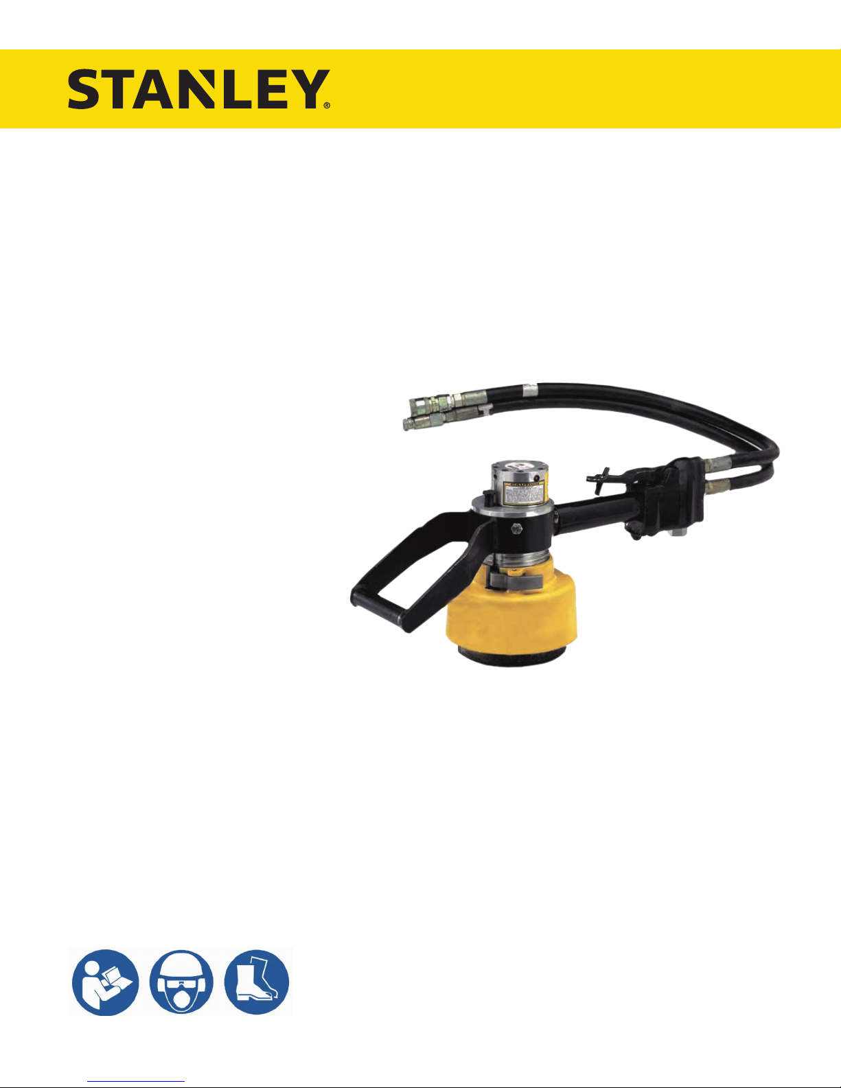
GR60
HYDRAULIC
GRINDER
USER MANUAL
Safety, Operation and Maintenance
© 2017 STANLEY Black & Decker, Inc.
New Britain, CT 06053
U.S.A.
28077 1/2018 Ver. 11
Page 2

Page 3
TABLE OF CONTENTS
SAFETY SYMBOLS ..................................................................................................................................................4
SAFETY PRECAUTIONS .......................................................................................................................................... 5
TOOL STICKERS & TAGS ........................................................................................................................................ 6
HOSE TYPES ............................................................................................................................................................7
HOSE RECOMMENDATIONS ..................................................................................................................................8
HTMA / EHTMA REQUIREMENTS ...........................................................................................................................9
OPERATION ............................................................................................................................................................ 10
OPERATION ............................................................................................................................................................ 11
TROUBLESHOOTING ............................................................................................................................................12
TOOL PROTECTION & CARE ................................................................................................................................13
SPECIFICATIONS ................................................................................................................................................... 14
ACCESSORIES.......................................................................................................................................................14
GR60 PARTS ILLUSTRATION ................................................................................................................................ 15
GR60 PARTS LIST ..................................................................................................................................................16
To ll out a product warranty validation form, and for information on your warranty,
visit www.stanleyinfrastructure.com and select the Company tab > Warranty.
Note: The warranty validation record must be submitted to validate the warranty.
SERVICING: This manual contains safety, operation and routine maintenance instructions. STANLEY Infrastructure
recommends that servicing of hydraulic tools, other than routine maintenance, must be performed by an authorized
and certied dealer. Please read the following warning.
SERIOUS INJURY OR DEATH COULD RESULT FROM THE IMPROPER REPAIR OR
SERVICE OF THIS TOOL.
REPAIRS AND / OR SERVICE TO THIS TOOL MUST ONLY BE DONE BY AN
AUTHORIZED AND CERTIFIED DEALER.
For the nearest certied dealer, call STANLEY Infrastructure at (503) 659-5660 and ask for a Customer Service Representative.
GR60 User Manual ◄ 3
Page 4
SAFETY SYMBOLS
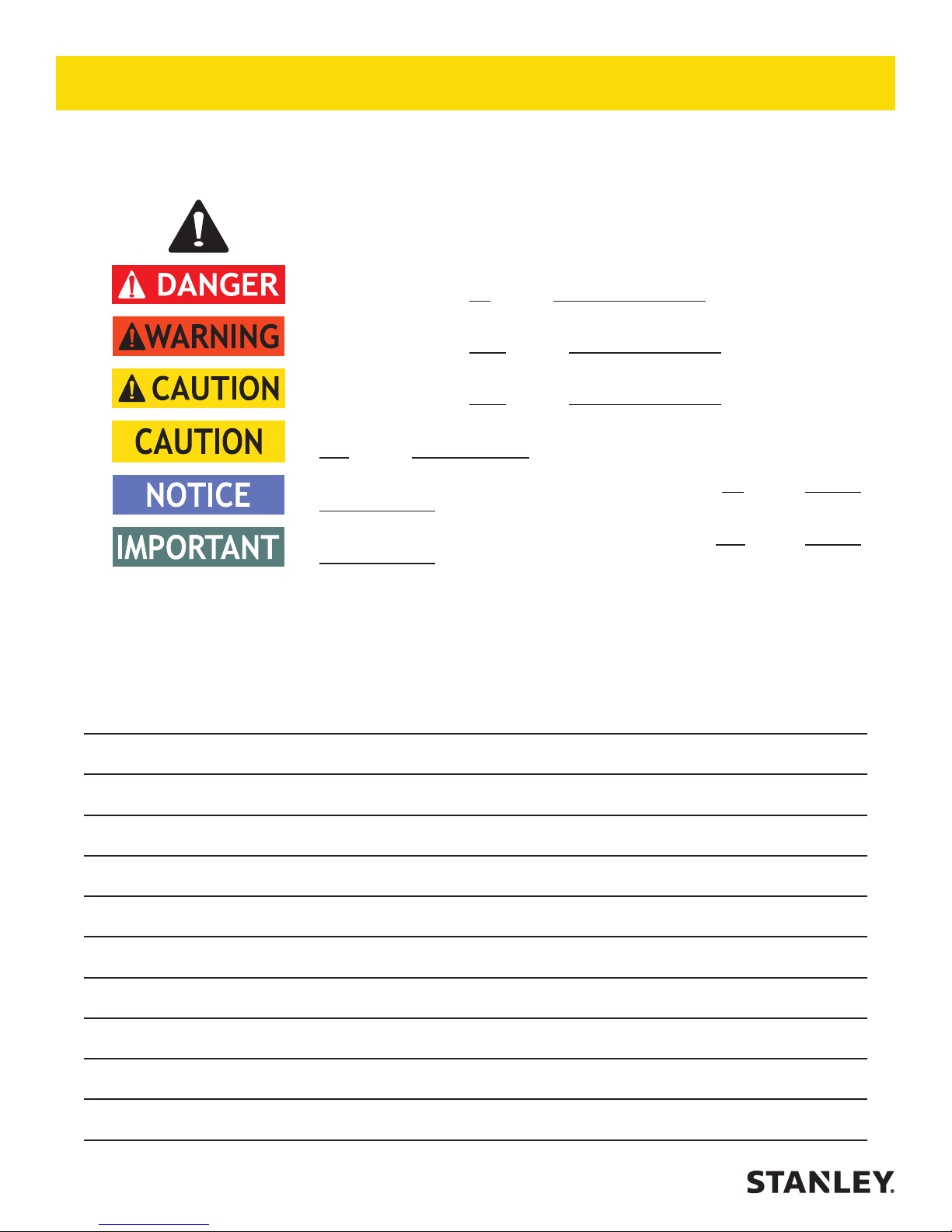
Safety symbols and signal words, as shown below, are used to emphasize all operator, maintenance and repair
actions which, if not strictly followed, could result in a life-threatening situation, bodily injury or damage to equipment.
This is the safety alert symbol. It is used to alert you to potential personal injury
hazards. Obey all safety messages that follow this symbol to avoid possible
injury or death.
This safety alert and signal word indicates an imminently hazardous situation
which, if not avoided, will result in death or serious injury.
This safety alert and signal word indicates a potentially hazardous situation
which, if not avoided, could result in death or serious injury.
This safety alert and signal word indicates a potentially hazardous situation
which, if not avoided, could result in death or serious injury.
This signal word indicates a potentially hazardous situation which, if not avoided,
may result in property damage.
This signal word indicates a situation which, if not avoided, will result in damage
to the equipment.
This signal word indicates a situation which, if not avoided, may result in damage
to the equipment.
Always observe safety symbols. They are included for your safety and for the protection of the tool.
LOCAL SAFETY REGULATIONS
Enter any local safety regulations here. Keep these instructions in an area accessible to the operator and
maintenance personnel.
4 ► GR60 User Manual
Page 5

SAFETY PRECAUTIONS
Tool operators and maintenance personnel must comply
with the safety precautions given in this manual and on
the stickers and tags attached to the tool and hose.
These precautions are given for your safety. Review
them carefully before operating the tool and before
performing general maintenance or repairs.
Supervising personnel should develop additional
precautions relating to the specic work area and local
safety regulations. Place the added precautions in the
space provided.
The GR60 Hydraulic Grinder will provide safe and
dependable service if operated in accordance with the
instructions given in this manual. Read and understand
this manual and any stickers and tags attached to the
tool and hoses before operation. Failure to do so could
result in personal injury or equipment damage.
• Operators must start in a work area without
bystanders. The operator must be familiar with all
prohibited work areas such as excessive slopes and
dangerous terrain conditions.
• Establish a training program for all operators to
ensure safe operation.
• Warning: Use of this tool on certain materials could
generate dust potentially containing a variety of
hazardous substances such as asbestos, silica or
lead. Inhalation of dust containing these or other
hazardous substances could result in serious injury,
cancer or death. Protect yourself and those around
you. Research and understand the materials you
are cutting. Follow correct safety procedures
and comply with all applicable national, state or
provisional health and safety regulations relating to
them, including, if appropriate arranging for the safe
disposal of the materials by a qualied person.
• Do not operate the tool unless thoroughly trained or
under the supervision of an instructor.
• Always wear safety equipment such as goggles, ear
and head protection at all times when operating the
tool.
• Do not inspect or clean the tool while the hydraulic
power source is connected. Accidental engagement
of the tool can cause serious injury.
• Always connect hoses to the tool hose couplers
before energizing the hydraulic power source. Be
sure all hose connections are tight.
• Do not operate the tool at oil temperatures above
140°F/60°C. High temperatures can cause operator
discomfort.
• Do not operate a damaged, improperly adjusted or
incompletely assembled tool.
• To avoid personal injury or equipment damage,
all tool repair, maintenance and service must only
be performed by authorized and properly trained
personnel.
• Always replace parts with replacement parts
recommended by STANLEY.
• Do not operate the tool with the wheel guard
removed.
• Never wear loose clothing that can get entangled in
the working parts of the tool.
• Keep all parts of your body away from the rotating
wheel. Long hair or loose clothing can become
drawn into rotating components.
• Do not overreach. Maintain proper footing and
balance at all times.
• Keep the wheel off all surfaces when starting the
grinder.
• Always hold the tool with both hands when the unit
is running. Use a rm grip.
• Keep all parts of your body away from the rotating
wheel.
GR60 User Manual ◄ 5
Page 6
The rated working pressure of the hydraulic hose must be equal to or higher than the relief valve setting on the
hydraulic system. There are three types of hydraulic hose that meet this requirement and are authorized for use with
STANLEY hydraulic tools. They are:
Certi ed non-conductive — constructed of thermoplastic or synthetic rubber inner tube, synthetic ber braid
reinforcement, and weather resistant thermoplastic or synthetic rubber cover. Hose labeled certifi ed non-
conductive is the only hose authorized for use near electrical conductors.
Wire-braided (conductive) — constructed of synthetic rubber inner tube, single or double wire braid
reinforcement, and weather resistant synthetic rubber cover. This hose is conductive and must never be used
near electrical conductors.
Fabric-braided (not certi ed or labeled non-conductive) — constructed of thermoplastic or synthetic rubber
inner tube, synthetic ber braid reinforcement, and weather resistant thermoplastic or synthetic rubber cover.
This hose is not certifi ed non-conductive and must never be used near electrical conductors.
HOSE SAFETY TAGS
To help ensure your safety, the following DANGER tags are attached to all hose purchased from STANLEY. DO
NOT REMOVE THESE TAGS.
If the information on a tag is illegible because of wear or damage, replace the tag immediately. A new tag may be
obtained from your STANLEY Distributor.
THE TAG SHOWN BELOW IS ATTACHED TO “CERTIFIED NON-CONDUCTIVE” HOSE
THE TAG SHOWN BELOW IS ATTACHED TO “CONDUCTIVE” HOSE.
(Shown smaller than actual size)
SIDE 1
DANGER
1. FAILURE TO USE HYDRAULIC HOSE LABELED AND CERTIFIED AS NON-CONDUCTIVE
WHEN USING HYDRAULIC TOOLS ON OR NEAR ELECTRIC LINES MAY RESULT IN
DEATH OR SERIOUS INJURY.
FOR PROPER AND SAFE OPERATION MAKE SURE THAT YOU HAVE BEEN PROPERLY
TRAINED IN CORRECT PROCEDURES REQUIRED FOR WORK ON OR AROUND
ELECTRIC LINES.
2. BEFORE USING HYDRAULIC HOSE LABELED AND CERTIFIED AS NON-CONDUCTIVE
ON OR NEAR ELECTRIC LINES. WIPE THE ENTIRE LENGTH OF THE HOSE AND FITTING
WITH A CLEAN DRY ABSORBENT CLOTH TO REMOVE DIRT AND MOISTURE AND TEST
HOSE FOR MAXIMUM ALLOWABLE CURRENT LEAKAGE IN ACCORDANCE WITH SAFETY
DEPARTMENT INSTRUCTIONS.
SEE OTHER SIDE
SIDE 2
DO NOT REMOVE THIS TAG
3. DO NOT EXCEED HOSE WORKING PRESSURE OR ABUSE HOSE. IMPROPER USE
OR HANDLING OF HOSE COULD RESULT IN BURST OR OTHER HOSE FAILURE.
KEEP HOSE AS FAR AWAY AS POSSIBLE FROM BODY AND DO NOT PERMIT DIRECT
CONTACT DURING USE. CONTACT AT THE BURST CAN CAUSE BODILY INJECTION
AND SEVERE PERSONAL INJURY.
4. HANDLE AND ROUTE HOSE CAREFULLY TO AVOID KINKING, ABRASION, CUTTING, OR
CONTACT WITH HIGH TEMPERATURE SURFACES. DO NOT USE IF KINKED. DO NOT
USE HOSE TO PULL OR LIFT TOOLS, POWER UNITS, ETC.
5. CHECK ENTIRE HOSE FOR CUTS CRACKS LEAKS ABRASIONS, BULGES, OR DAM-
AGE TO COUPLINGS IF ANY OF THESE CONDITIONS EXIST, REPLACE THE HOSE
IMMEDIATELY. NEVER USE TAPE OR ANY DEVICE TO ATTEMPT TO MEND THE HOSE.
6. AFTER EACH USE STORE IN A CLEAN DRY AREA.
SEE OTHER SIDE
DANGER
DO NOT REMOVE THIS TAG
DANGER
(Shown smaller than actual size)
SIDE 2
5. CHECK ENTIRE HOSE FOR CUTS CRACKS LEAKS ABRASIONS, BULGES, OR DAMAGE TO
COUPLINGS IF ANY OF THESE CONDITIONS EXIST, REPLACE THE HOSE IMMEDIATELY.
NEVER USE TAPE OR ANY DEVICE TO ATTEMPT TO MEND THE HOSE.
6. AFTER EACH USE STORE IN A CLEAN DRY AREA.
DANGER
DO NOT REMOVE THIS TAG
DANGER
SIDE 1
1. DO NOT USE THIS HYDRAULIC HOSE ON OR NEAR ELECTRIC LINES. THIS HOSE IS
NOT LABELED OR CERTIFIED AS NON-CONDUCTIVE. USING THIS HOSE ON OR NEAR
ELECTRICAL LINES MAY RESULT IN DEATH OR SERIOUS INJURY.
2. FOR PROPER AND SAFE OPERATION MAKE SURE THAT YOU HAVE BEEN PROPERLY
TRAINED IN CORRECT PROCEDURES REQUIRED FOR WORK ON OR AROUND ELEC-
TRIC LINES.
3. DO NOT EXCEED HOSE WORKING PRESSURE OR ABUSE HOSE. IMPROPER USE OR
HANDLING OF HOSE COULD RESULT IN BURST OR OTHER HOSE FAILURE. KEEP HOSE
AS FAR AWAY AS POSSIBLE FROM BODY AND DO NOT PERMIT DIRECT CONTACT
DURING USE. CONTACT AT THE BURST CAN CAUSE BODILY INJECTION AND SEVERE
PERSONAL INJURY.
4. HANDLE AND ROUTE HOSE CAREFULLY TO AVOID KINKING, CUTTING, OR CONTACT
WITH HIGH TEMPERATURE SURFACES. DO NOT USE IF KINKED. DO NOT USE HOSE TO
PULL OR LIFT TOOLS, POWER UNITS, ETC.
DO NOT REMOVE THIS TAG
DANGER
SEE OTHER SIDE
SEE OTHER SIDE
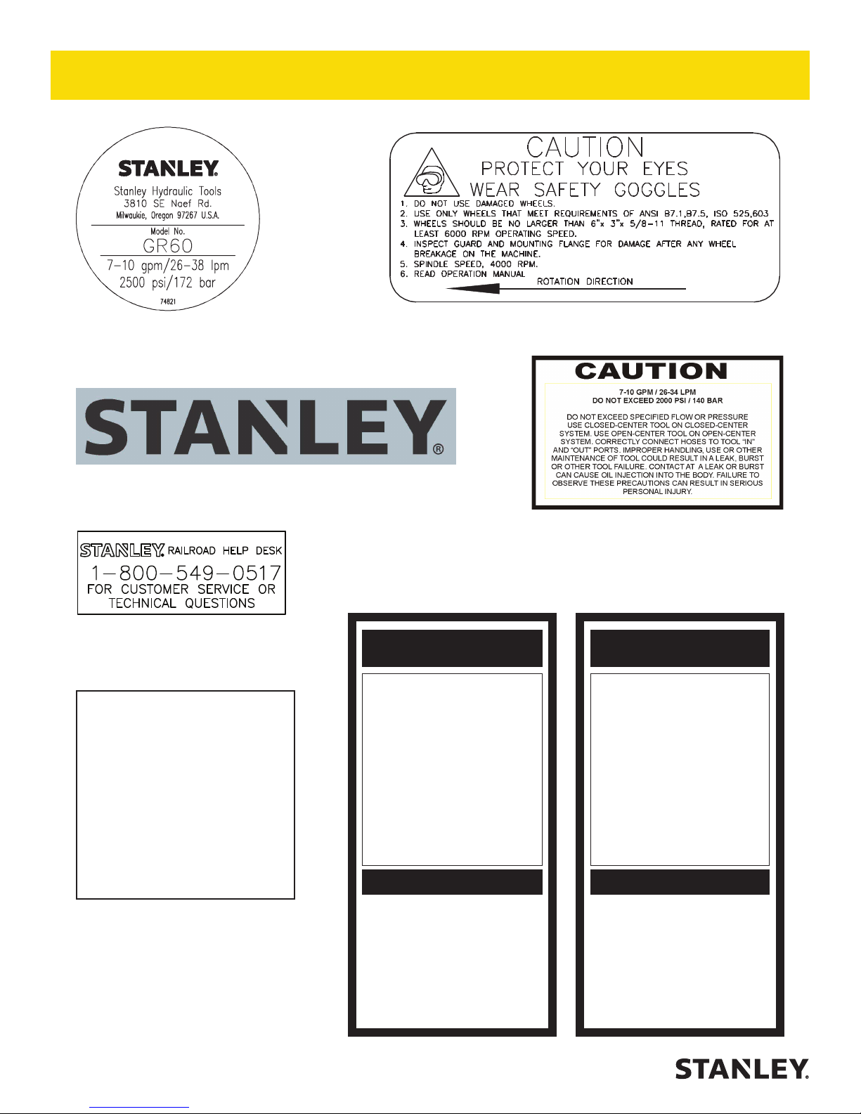
TOOL STICKERS & TAGS
P/N-74821
Name Tag
P/N-74820
Stanley Logo Sticker
P/N-25790
Caution Sticker
P/N-73680
Railroad Help Desk Sticker
NOTE:
THE INFORMATION LISTED
ON THE STICKERS SHOWN,
MUST BE LEGIBLE AT ALL
TIMES.
REPLACE DECALS IF
THEY BECOME WORN OR
DAMAGED. REPLACEMENTS
ARE AVAILABLE FROM
YOUR LOCAL STANLEY
DISTRIBUTOR.
The safety tag (P/N 15875) at right is
attached to the tool when shipped from
the factory. Read and understand the
safety instructions listed on this tag before
removal. We suggest you retain this tag and
attach it to the tool when not in use.
6 ► GR60 User Manual
P/N-03787
GPM Sticker
1. FAILURE TO USE HYDRAULIC HOSE LABELED AND CERTIFIED AS NON-CONDUCTIVE WHEN USING HYDRAULIC
TOOLS ON OR NEAR ELECTRICAL LINES MAY RESULT IN
DEATH OR SERIOUS INJURY.
BEFORE USING HOSE LABELED AND CERTIFIED AS NON-
CONDUCTIVE ON OR NEAR ELECTRIC LINES BE SURE THE
HOSE IS MAINTAINED AS NON-CONDUCTIVE. THE HOSE
SHOULD BE REGULARLY TESTED FOR ELECTRIC CURRENT LEAKAGE IN ACCORDANCE WITH YOUR SAFETY
DEPARTMENT INSTRUCTIONS.
2. A HYDRAULIC LEAK OR BURST MAY CAUSE OIL INJECTION INTO THE BODY OR CAUSE OTHER SEVERE
PERSONAL INJURY.
A. DO NOT EXCEED SPECIFIED FLOW AND PRESSURE
FOR THIS TOOL. EXCESS FLOW OR PRESSURE MAY
CAUSE A LEAK OR BURST.
B. DO NOT EXCEED RATED WORKING PRESSURE OF
HYDRAULIC HOSE USED WITH THIS TOOL. EXCESS
PRESSURE MAY CAUSE A LEAK OR BURST.
C. CHECK TOOL HOSE COUPLERS AND CONNECTORS
DAILY FOR LEAKS. DO NOT FEEL FOR LEAKS WITH
YOUR HANDS. CONTACT WITH A LEAK MAY RESULT
IN SEVERE PERSONAL INJURY.
IMPORTANT
READ OPERATION MANUAL AND
SAFETY INSTRUCTIONS FOR THIS
TOOL BEFORE USING IT.
USE ONLY PARTS AND REPAIR
PROCEDURES APPROVED BY
STANLEY AND DESCRIBED IN THE
OPERATION MANUAL.
TAG TO BE REMOVED ONLY BY
TOOL OPERATOR.
SEE OTHER SIDE
SAFETY TAG P/N 15875 (Shown smaller then actual size)
D. DO NOT LIFT OR CARRY TOOL BY THE HOSES. DO
NOT ABUSE HOSE. DO NOT USE KINKED, TORN OR
DAMAGED HOSE.
3. MAKE SURE HYDRAULIC HOSES ARE PROPERLY CON-
NECTED TO THE TOOL BEFORE PRESSURING SYSTEM.
SYSTEM PRESSURE HOSE MUST ALWAYS BE CONNECTED TO TOOL “IN” PORT. SYSTEM RETURN HOSE
MUST ALWAYS BE CONNECTED TO TOOL “OUT” PORT.
REVERSING CONNECTIONS MAY CAUSE REVERSE
TOOL OPERATION WHICH CAN RESULT IN SEVERE
PERSONAL INJURY.
4. DO NOT CONNECT OPEN-CENTER TOOLS TO CLOSED-
CENTER HYDRAULIC SYSTEMS. THIS MAY RESULT IN
LOSS OF OTHER HYDRAULIC FUNCTIONS POWERED BY
THE SAME SYSTEM AND/OR SEVERE PERSONAL INJURY.
5. BYSTANDERS MAY BE INJURED IN YOUR WORK AREA.
KEEP BYSTANDERS CLEAR OF YOUR WORK AREA.
6. WEAR HEARING, EYE, FOOT, HAND AND HEAD PROTECTION.
7. TO AVOID PERSONAL INJURY OR EQUIPMENT DAMAGE,
ALL TOOL REPAIR MAINTENANCE AND SERVICE MUST
ONLY BE PERFORMED BY AUTHORIZED AND PROPERLY
TRAINED PERSONNEL.
IMPORTANT
READ OPERATION MANUAL AND
SAFETY INSTRUCTIONS FOR THIS
USE ONLY PARTS AND REPAIR
PROCEDURES APPROVED BY
STANLEY AND DESCRIBED IN THE
TAG TO BE REMOVED ONLY BY
DANGERDANGER
TOOL BEFORE USING IT.
OPERATION MANUAL.
TOOL OPERATOR.
SEE OTHER SIDE
Page 7
HOSE TYPES
The rated working pressure of the hydraulic hose must be equal to or higher than the relief valve setting on the
hydraulic system. There are three types of hydraulic hose that meet this requirement and are authorized for use with
STANLEY hydraulic tools. They are:
Certi ed non-conductive — constructed of thermoplastic or synthetic rubber inner tube, synthetic ber braid
reinforcement, and weather resistant thermoplastic or synthetic rubber cover. Hose labeled certifi ed non-
conductive is the only hose authorized for use near electrical conductors.
Wire-braided (conductive) — constructed of synthetic rubber inner tube, single or double wire braid
reinforcement, and weather resistant synthetic rubber cover. This hose is conductive and must never be used
near electrical conductors.
Fabric-braided (not certi ed or labeled non-conductive) — constructed of thermoplastic or synthetic rubber
inner tube, synthetic ber braid reinforcement, and weather resistant thermoplastic or synthetic rubber cover.
This hose is not certifi ed non-conductive and must never be used near electrical conductors.
HOSE SAFETY TAGS
To help ensure your safety, the following DANGER tags are attached to all hose purchased from STANLEY. DO
NOT REMOVE THESE TAGS.
If the information on a tag is illegible because of wear or damage, replace the tag immediately. A new tag may be
obtained from your STANLEY Distributor.
THE TAG SHOWN BELOW IS ATTACHED TO “CERTIFIED NON-CONDUCTIVE” HOSE
DANGER
1. FAILURE TO USE HYDRAULIC HOSE LABELED AND CERTIFIED AS NON-CONDUCTIVE
WHEN USING HYDRAULIC TOOLS ON OR NEAR ELECTRIC LINES MAY RESULT IN
DEATH OR SERIOUS INJURY.
FOR PROPER AND SAFE OPERATION MAKE SURE THAT YOU HAVE BEEN PROPERLY
TRAINED IN CORRECT PROCEDURES REQUIRED FOR WORK ON OR AROUND
ELECTRIC LINES.
2. BEFORE USING HYDRAULIC HOSE LABELED AND CERTIFIED AS NON-CONDUCTIVE
ON OR NEAR ELECTRIC LINES. WIPE THE ENTIRE LENGTH OF THE HOSE AND FITTING
WITH A CLEAN DRY ABSORBENT CLOTH TO REMOVE DIRT AND MOISTURE AND TEST
HOSE FOR MAXIMUM ALLOWABLE CURRENT LEAKAGE IN ACCORDANCE WITH SAFETY
DEPARTMENT INSTRUCTIONS.
DO NOT REMOVE THIS TAG
SEE OTHER SIDE
SIDE 1
3. DO NOT EXCEED HOSE WORKING PRESSURE OR ABUSE HOSE. IMPROPER USE
OR HANDLING OF HOSE COULD RESULT IN BURST OR OTHER HOSE FAILURE.
KEEP HOSE AS FAR AWAY AS POSSIBLE FROM BODY AND DO NOT PERMIT DIRECT
CONTACT DURING USE. CONTACT AT THE BURST CAN CAUSE BODILY INJECTION
AND SEVERE PERSONAL INJURY.
4. HANDLE AND ROUTE HOSE CAREFULLY TO AVOID KINKING, ABRASION, CUTTING, OR
CONTACT WITH HIGH TEMPERATURE SURFACES. DO NOT USE IF KINKED. DO NOT
USE HOSE TO PULL OR LIFT TOOLS, POWER UNITS, ETC.
5. CHECK ENTIRE HOSE FOR CUTS CRACKS LEAKS ABRASIONS, BULGES, OR DAM-
AGE TO COUPLINGS IF ANY OF THESE CONDITIONS EXIST, REPLACE THE HOSE
IMMEDIATELY. NEVER USE TAPE OR ANY DEVICE TO ATTEMPT TO MEND THE HOSE.
6. AFTER EACH USE STORE IN A CLEAN DRY AREA.
(Shown smaller than actual size)
DANGER
DANGER
SEE OTHER SIDE
SIDE 2
THE TAG SHOWN BELOW IS ATTACHED TO “CONDUCTIVE” HOSE.
DANGER
DANGER
1. DO NOT USE THIS HYDRAULIC HOSE ON OR NEAR ELECTRIC LINES. THIS HOSE IS
NOT LABELED OR CERTIFIED AS NON-CONDUCTIVE. USING THIS HOSE ON OR NEAR
ELECTRICAL LINES MAY RESULT IN DEATH OR SERIOUS INJURY.
2. FOR PROPER AND SAFE OPERATION MAKE SURE THAT YOU HAVE BEEN PROPERLY
TRAINED IN CORRECT PROCEDURES REQUIRED FOR WORK ON OR AROUND ELEC-
TRIC LINES.
3. DO NOT EXCEED HOSE WORKING PRESSURE OR ABUSE HOSE. IMPROPER USE OR
HANDLING OF HOSE COULD RESULT IN BURST OR OTHER HOSE FAILURE. KEEP HOSE
AS FAR AWAY AS POSSIBLE FROM BODY AND DO NOT PERMIT DIRECT CONTACT
DURING USE. CONTACT AT THE BURST CAN CAUSE BODILY INJECTION AND SEVERE
PERSONAL INJURY.
4. HANDLE AND ROUTE HOSE CAREFULLY TO AVOID KINKING, CUTTING, OR CONTACT
WITH HIGH TEMPERATURE SURFACES. DO NOT USE IF KINKED. DO NOT USE HOSE TO
PULL OR LIFT TOOLS, POWER UNITS, ETC.
DO NOT REMOVE THIS TAG
SEE OTHER SIDE
SIDE 1
5. CHECK ENTIRE HOSE FOR CUTS CRACKS LEAKS ABRASIONS, BULGES, OR DAMAGE TO
COUPLINGS IF ANY OF THESE CONDITIONS EXIST, REPLACE THE HOSE IMMEDIATELY.
NEVER USE TAPE OR ANY DEVICE TO ATTEMPT TO MEND THE HOSE.
6. AFTER EACH USE STORE IN A CLEAN DRY AREA.
(Shown smaller than actual size)
DANGER
SEE OTHER SIDE
SIDE 2
DO NOT REMOVE THIS TAG
DO NOT REMOVE THIS TAG
GR60 User Manual ◄ 7
Page 8
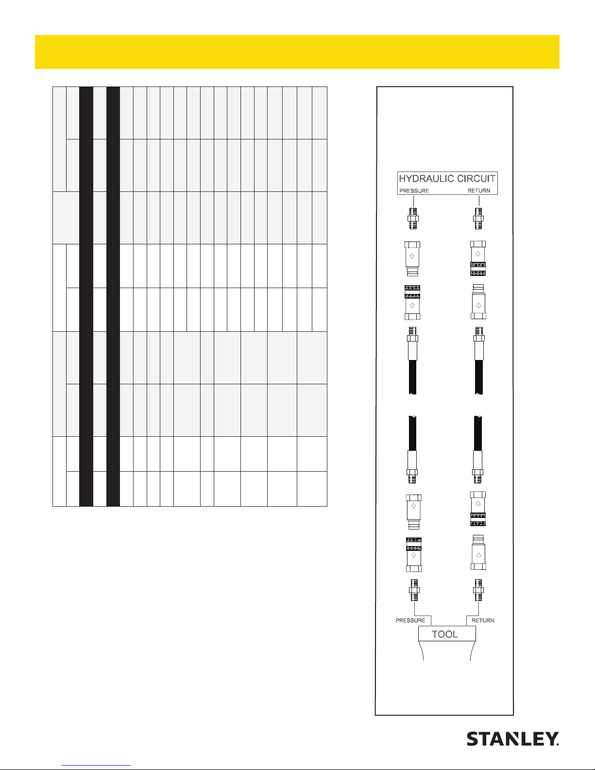
Min. Working Pressure
USE
Press/Return)
(
HOSE RECOMMENDATIONS
Certi ed Non-Conductive Hose - Fiber Braid - for Utility Bucket Trucks
Oil Flow Hose Lengths Inside Diameter
GPM LPM FEET METERS INCH MM PSI BAR
4-9 15-34 up to 10 up to 3 3/8 10 Both 2250 155
Conductive Hose - Wire Braid or Fiber Braid -DO NOT USE NEAR ELECTRICAL CONDUCTORS
4-6 15-23 up to 25 up to 7.5 3/8 10 Both 2500 175
4-6 15-23 26-100 7.5-30 1/2 13 Both 2500 175
5-10.5 19-40 up to 50 up to 15 1/2 13 Both 2500 175
5-10.5 19-40 51-100 15-30 5/8 16 Both 2500 175
5/8 16 Pressure 2500 175
3/4 19 Return 2500 175
5-10.5 19-40 100-300 30-90
10-13 38-49 up to 50 up to 15 5/8 16 Both 2500 175
5/8 16 Pressure 2500 175
3/4 19 Return 2500 175
10-13 38-49 51-100 15-30
3/4 19 Pressure 2500 175
1 25.4 Return 2500 175
10-13 38-49 100-200 30-60
5/8 16 Pressure 2500 175
13-16 49-60 up to 25 up to 8
3/4 19 Return 2500 175
3/4 19 Pressure 2500 175
1 25.4 Return 2500 175
13-16 49-60 26-100 8-30
PRESSURE
<<< FLOW
RETURN
FLOW >>>
Figure 1. Typical Hose Connections
Tool to Hydraulic Circuit Hose
Recommendations
The chart to the right shows recommended
minimum hose diameters for various
hose lengths based on gallons per minute
(GPM)/liters per minute (LPM). These
recommendations are intended to keep return
line pressure (back pressure) to a minimum
acceptable level to ensure maximum tool
performance.
This chart is intended to be used for hydraulic
tool applications only based on STANLEY tool
8 ► GR60 User Manual
operating requirements and should not be
used for any other applications.
All hydraulic hose must have at least a
rated minimum working pressure equal to
the maximum hydraulic system relief valve
setting.
All hydraulic hose must meet or exceed
speci cations as set forth by SAE J517.
Page 9
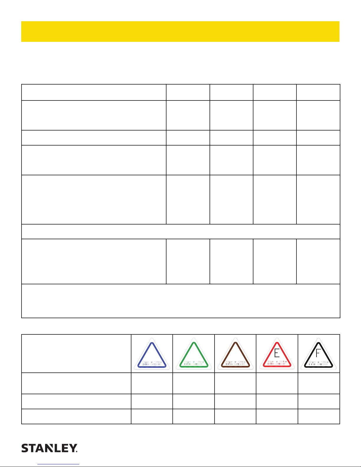
HTMA / EHTMA REQUIREMENTS
HTMA / EHTMA REQUIREMENTS
TOOL TYPE
HTMA
HYDRAULIC SYSTEM REQUIREMENTS
Flow range
Nominal operating pressure
(At the power supply outlet)
System relief valve setting
(At the power supply outlet)
Maximum back pressure
(At tool end of the return hose)
Measured at a max uid viscosity of:
(At minimum operating temperature)
Temperature: Suf cient heat rejection capacity to limit
maximum uid temperature to:
(At maximum expected ambient temperature)
Minimum cooling capacity at a temperature difference of
between ambient and uid temps
NOTE: Do not operate the tool at oil temperatures above 140° F (60° C). Operation at higher temperatures can cause operator
discomfort at the tool.
Filter minimum full- ow ltration 25 microns 25 microns 25 microns 25 microns
Sized for ow of at least:
(For cold temp startup and maximum dirt-holding capacity)
Hydraulic uid, petroleum based (premium grade, antiwear, non-conductive) Viscosity (at minimum and maximum
operating temps)
NOTE: When choosing hydraulic uid, the expected oil temperature extremes that will be experienced in service determine the most
suitable temperature viscosity characteristics. Hydraulic uids with a viscosity index over 140 will meet the requirements over a wide
range of operating temperatures.
TYPE I TYPE II TYPE RR TYPE III
4-6 GPM
(15-23 LPM)
1500 psi
(103 bar)
2100-2250 psi
(145-155 bar)
250 psi
(17 bar)
400 ssu*
(82 centistokes)
140° F
(60° C)
3 hp
(2.24 kW)
40° F
(22° C)
30 GPM
(114 LPM)
100-400 ssu
(20-82
centistokes)
7-9 GPM
(26-34 LPM)
1500 psi
(103 bar)
2100-2250 psi
(145-155 bar)
250 psi
(17 bar)
400 ssu*
(82 centistokes)
140° F
(60° C)
5 hp
(3.73 kW)
40° F
(22° C)
30 GPM
(114 LPM)
100-400 ssu
(20-82
centistokes)
9-10.5 GPM
(34-40 LPM)
1500 psi
(103 bar)
2200-2300 psi
(152-159 bar)
250 psi
(17 bar)
400 ssu*
(82 centistokes)
140° F
(60° C)
6 hp
(5.22 kW)
40° F
(22° C)
30 GPM
(114 LPM)
100-400 ssu
(20-82
centistokes)
11-13 GPM
(42-49 LPM)
2100-2250 psi
(145-155 bar)
(82 centistokes)
100-400 ssu
centistokes)
1500 psi
(103 bar)
250 psi
(17 bar)
400 ssu*
140° F
(60° C)
7 hp
(4.47 kW)
40° F
(22° C)
30 GPM
(114 LPM)
(20-82
*SSU = Saybolt Seconds Universal
EHTMA
HYDRAULIC SYSTEM
REQUIREMENTS
Flow range
Nominal operating pressure
(At the power supply outlet)
System relief valve setting
(At the power supply outlet)
NOTE: These are general hydraulic system requirements. See tool speci cation page for tool speci c requirements.
B
3.5-4.3 GPM
(13.5-16.5
LPM)
1870 psi
(129 bar)
2495 psi
(172 bar)
C
4.7-5.8 GPM
(18-22 LPM)
1500 psi
(103 bar)
2000 psi
(138 bar)
CLASSIFICATION
D
7.1-8.7 GPM
(27-33 LPM)
1500 psi
(103 bar)
2000 psi
(138 bar)
9.5-11.6 GPM
(36-44 LPM)
1500 psi
(103 bar)
2000 psi
(138 bar)
GR60 User Manual ◄ 9
11.8-14.5 GPM
(45-55 LPM)
1500 psi
(103 bar)
2000 psi
(138 bar)
Page 10
OPERATION
PREPARATION PROCEDURES
Each unit, as shipped, has no special unpacking or
assembly requirements prior to usage. Inspection to
assure the unit was not damaged in shipping and does
not contain packing debris is all that is required. After
installation of a grinding wheel a unit may be put to use.
CHECK HYDRAULIC POWER SOURCE
1. Using a calibrated ow meter and pressure gauge,
check that the hydraulic power source develops a
ow of 7-10 GPM/26-38 LPM at 1500-2000 psi/105-
140 bar.
2. Make certain the hydraulic power source is equipped
with a relief valve set to open at 2100-2250 psi/145-
155 bar minimum.
3. Check that the hydraulic circuit matches the tool for
open-center (OC) or closed-center (CC) operation.
CHECK TOOL
1. Make sure all tool accessories are correctly installed.
Failure to install tool accessories properly can result
in damage to the tool or personal injury.
2. There should be no signs of leaks.
3. The tool should be clean, with all ttings and
fasteners tight.
CHECK TRIGGER MECHANISM
1. Check that the trigger operates smoothly and is free
to travel between the “ON” and “OFF” positions.
CHECK GUARD ASSEMBLY
1. Inspect the wheel guard assembly for cracks and
other structural damage.
INSTALLING AND REMOVING GRINDING
WHEELS
Read and become familiar with the sections in this
manual on safety precautions, tool stickers and tags,
hydraulic hose requirements, hydraulic requirements,
and pre-operation procedures before using this product.
Never over-tighten the grinding wheel by impacting
the wrench with a mallet or hammer. Sufcient
torque is attained by hand-tightening the wheel
with a strap wrench or for wheels secured with
capscrews, hand tightening with a socket wrench
while depressing the push lock.
Note: Use 6-inch diameter up to 3-inch thick (Type 6
for USA/Type 36 for CE) grinding wheels with a 5/811 threaded arbor hole. Only use grinding wheels
which comply with ANSI B7.5/ISO 525, 603.
2. Depress the push lock (6) and screw the grinding
wheel onto the main shaft (13) and tighten using a
strap wrench.
3. Adjust guard to desired height.
CONNECT HOSES
1. Wipe all hose couplers with a clean lint-free cloth
before making connections.
2. Connect the hoses from the hydraulic power
source to the hose couplers on the grinder. It is a
good practice to connect the return hose rst and
disconnect it last to minimize or avoid trapped
pressure within the grinder motor.
3. Observe ow indicators stamped on hose couplers
to be sure that oil will ow in the proper direction.
The female coupler is the inlet coupler.
Note: The pressure increase in uncoupled hoses
left in the sun may result in making them difcult to
connect. When possible, connect the free ends of
operating hoses together.
OPERATING PROCEDURES
1. Observe all safety precautions.
2. Always start the grinder with the grinding wheel
away from the work surface.
3. Move the hydraulic circuit control valve to the “ON”
position.
4. Disengage the safety thumb latch (42) and squeeze
10 ► GR60 User Manual
Page 11

OPERATION
the trigger momentarily. If the grinder does not
operate, the hoses might be reversed. Verify correct
connection of the hoses before continuing.
5. Start the grinder and move the grinding wheel or
cone to the work surface.
6. Grind a small amount of material at a time.
7. As the grinding stone wears, adjust guard height by
depressing the guard latch (26) and rotate the guard
to lower or raise height.
COLD WEATHER OPERATION
If the grinder is to be used during cold weather, preheat
the hydraulic uid at low engine speed. When using the
normally recommended uids, uid temperature should
be at or above 50° F/10° C (400 ssu/82 centistokes)
before use.
GR60 User Manual ◄ 11
Page 12
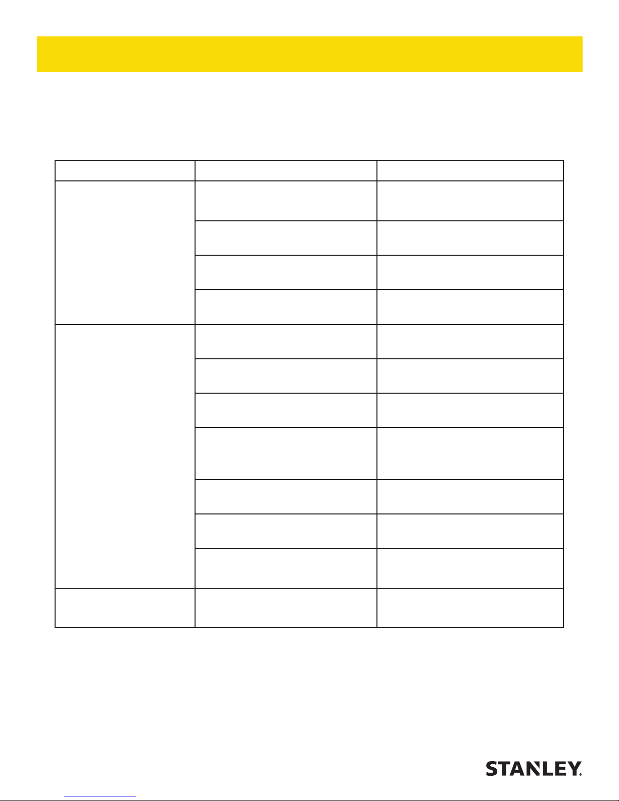
TROUBLESHOOTING
If symptoms of poor performance develop, the following chart can be used as a guide to correct the problem. When
diagnosing faults in operation of the grinder, always check that the hydraulic power source is supplying the correct
hydraulic ow and pressure to the grinder as listed in the table. Use a owmeter known to be accurate. Check the
ow with the hydraulic oil temperature at least 80°F/27°C.
Problem Cause Remedy
Grinder does not run Hydraulic power source not functioning. Check power source for proper ow
and pressure (7-10 GPM/ 26-38 LPM
@1500-2000 psi/ 105-140 bar)
Couplers or hoses are blocked Locate and remove restriction
Hydraulic motor failure Inspect and repair
Hydraulic lines are not connected. Connect lines
Grinder operates too slowly. Hydraulic motor speed is too low. Check power unit for proper ow (7-10
GPM/ 36-38 LPM).
Hydraulic back pressure Check hydraulic system for excessive
back pressure (over 250 psi/ 17 bar).
Couplers or hoses are blocked. Locate and remove restriction.
Oil is too hot (above 140° F/ 60° C) or
too cold (below 60° F/ 16° C).
Relief valve set too low. Adjust the relief valve to 2100-2250 psi/
Hydraulic motor is worn. Inspect, repair or replace.
Flow control is malfunctioning. Have the ow control and valve body
Grinder operates too fast. Flow control is malfunctioning. Have ow control and valve body
Check hydraulic power source for proper
oil temperature. Bypass cooler to warm
oil or provide cooler to maintain proper
temperature.
145-155 bar.
serviced at an authorized STANLEY
service center.
serviced at an authorized STANLEY
service center.
12 ► GR60 User Manual
Page 13
TOOL PROTECTION & CARE
In addition to the safety precautions found in
this manual, observe the following for equipment
protection and care.
• Make sure all couplers are wiped clean
before connection.
• The hydraulic circuit control valve must
be in the “OFF” position when coupling or
uncoupling hydraulic tools. Failure to do so
may result in damage to the quick couplers
and cause overheating of the hydraulic
system.
• Always store the tool in a clean dry space,
safe from damage or pilferage.
• Make sure the circuit PRESSURE hose
(with male quick disconnect) is connected
to the “IN” port. The circuit RETURN
hose (with female quick disconnect)
is connected to the opposite port. Do
not reverse circuit ow. This can cause
damage to internal seals.
• Do not exceed the rated ow (see
“SPECIFICATIONS” on page 14) in this
manual for correct ow rate and model
number. Rapid failure of the internal seals
may result.
• Always keep critical tool markings, such as
warning stickers and tags, legible.
• Tool repair should be performed by
experienced personnel only.
• Make certain that the recommended relief
valves are installed in the pressure side of
the system.
• Do not use the tool for applications for
which it was not intended.
• Always replace hoses, couplings and
other parts with replacement parts
recommended by STANLEY. Supply hoses
must have a minimum working pressure
rating of 2500 psi/172 bar.
GR60 User Manual ◄ 13
Page 14

SPECIFICATIONS
SPECIFICATIONS
Wheel Capacity .......................................................6 inch dia. x 3 inch thick x 5/8-11 threaded arbor (Type 6) USA
.............................................................................................150 mm x 60 mm x 5/8-11 threaded arbor (Type 36) CE
Pressure Range................................................................................................................1000-2000 psi / 70-140 bar
Maximum Back Pressure.................................................................................................................... 250 psi / 17 bar
Flow Range ............................................................................................................................7-10 GPM / 26-38 LPM
Porting ................................................................................................................................................. -8 SAE O-Ring
Couplers ........................................................................................EHTMA / HTMA Flush Face Type Male & Female
Connect Size & Type ........................................................................................................ 3/8 inch Male Pipe Adapter
Hose Whips ........................................................................................................................................................... Yes
Overall Length (w/o Hose Whips) .................................................................................................18 inches / 45.7 cm
Overall Width .............................................................................................................................10.5 inches / 26.7 cm
Weight (w/couplers) ............................................................................................................................20.3 lbs / 9.2 kg
Maximum Fluid Temperature ................................................................................................................ 140° F / 60° C
RPM ............................................................................................................................................................. 4000 Max
ACCESSORIES
Cup Stone Grinding Wheel (6 inch x 3 inch x 5/8-11 Norton Norzon IV) ........................................................... 28597
14 ► GR60 User Manual
Page 15
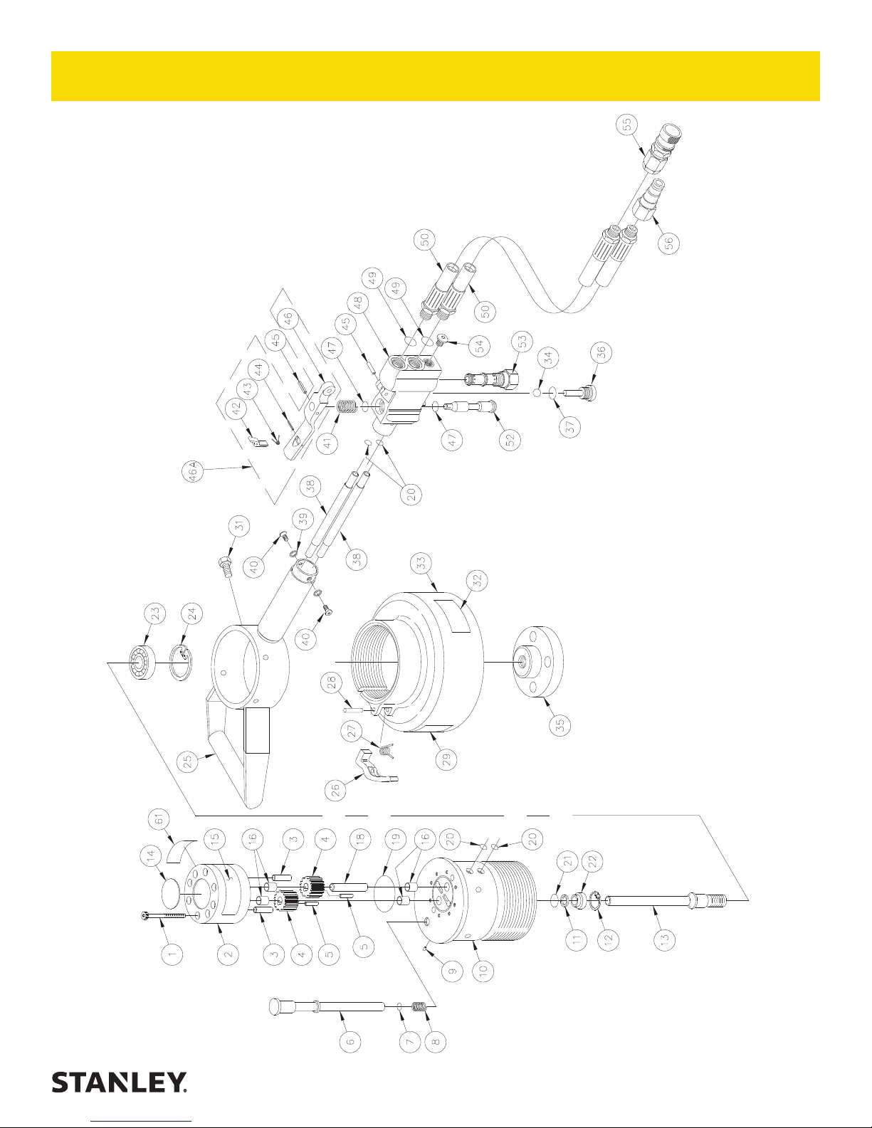
GR60 PARTS ILLUSTRATION
GR60 CUP STONE GRINDER
GR60 User Manual ◄ 15
Page 16
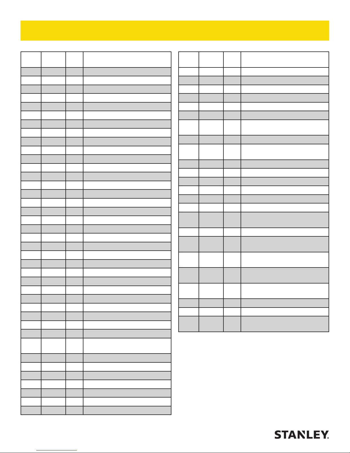
GR60 PARTS LIST
ITEM
NO.
1 00120 8 CAPSCREW
2 25188 1 GEAR CHAMBER ASSY
3 0713 2 DOWEL PIN
4 25718 2 DRIVE GEAR
5 06881 2 NEEDLE ROLLER
6 25612 1 PUSH LOCK
7 00354 1 O-RING
8 25788 1 COIL SPRING
9 02837 1 SET SCREW
10 25792 1 SHAFT HOUSING ASSY
11 00214 1 QUAD RING
12 00170 1 RETAINING RING
13 28127 1 MAIN SHAFT
14 74821 1 NAME TAG
15 03787 1 GPM STICKER
16 06316 4 BUSHING
18 73309 1 IDLER SHAFT KEYED
19 00178 1 O-RING
20 00018 4 O-RING
21 350771 1 O-RING
22 30333 1 SEAL GLAND
23 25947 1 BEARING
24 00633 1 RETAINING RING
25 31822 1 ASSIST HANDLE ASSY
26 25121 1 GUARD LATCH
27 25464 1 SPRING
28 17668 1 ROLL PIN
29 74820 1 STANLEY STICKER
30 ---- -- NO ITEM
31 02525 4 CAPSCREW
32 73680 1 RAILROAD HELP DESK DECAL
33 25783 1 GUARD ASSY (INCLUDES
34 20145 1 STEEL BALL
35 25784 1 DRIVE FLANGE
36 24289 1 PLUG
37 01411 1 O-RING
38 25215 2 OIL TUBE
39 00032 2 LOCK WASHER
40 30366 2 CAPSCREW
PART
NO.
QTY DESCRIPTION
ITEMS 26, 27 & 28)
ITEM
NO.
41 04097 1 SPRING
42 27441 1 THUMB LATCH
43 27445 1 SPRING
44 01851 1 ROLL PIN
45 00114 2 ROLL PIN
46 74061 1 TRIGGER
46A 27594 1 TRIGGER ASSY
47 01211 2 O-RING
48 28595 1 VALVE BODY ASSY
49 01605 1 O-RING
50 25618 2 HOSE ASSY (GR601215C)
51 ---- -- NO ITEM
52 04098 1 VALVE SPOOL ASSY
53 28914 1 FLOW REGULATOR CAR-
54 350041 1 PLUG
55 03972 1 FEMALE COUPLER BODY
56 03973 1 MALE COUPLER BODY
61 25790 1 CAUTION STICKER
PART
NO.
58630 2 HOSE ASSY (GR60212S)
66728 2 HOSE ASSY (GR60121B)
81158 1 FEMALE COUPLER BODY
81159 1 MALE COUPLER BODY
28967 1 SEAL KIT (INCL. 7, 11, 19-21,
QTY DESCRIPTION
(INCL. 42-44, 46)
(INCL 34, 36-37)
TRIDGE (PRE-SET)
(GR601215, GR601215C)
(GR60121B)
(GR601215, GR601215C)
(GR60121B)
47, 49)
16 ► GR60 User Manual
Page 17

Page 18

Page 19

Page 20

STANLEY Infrastructure
6430 SE Lake Road
Portland, Oregon 97222 USA
(503) 659-5660 / Fax (503) 652-1780
www.stanleyinfrastructure.com
 Loading...