

Page 1
VEA EL ESPAÑOL EN LA CONTRAPORTADA.
SAVE THIS MANUAL FOR FUTURE REFERENCE.
INSTRUCTIVO DE OPERACIÓN, CENTROS DE SERVICIO Y PÓLIZADE GARANTÍA.
ADVERTENCIA: LÉASE ESTE INSTRUCTIVO ANTES DE USAR EL PRODUCTO.
INSTRUCTION MANUAL
OOOOrrrrbbbbiiiittttaaaallll AAAAccccttttiiiioooonnnn JJJJiiiiggggSSSSaaaawwww wwwwiiiitttthhhh LLLLaaaasssseeeerr
rr
Catalog Number
FS6000JSL
T
T
HANK
HANK
YOU
YOU
FOR
FOR
CHOOSING
CHOOSING
F
F
IREST
IREST
ORM
ORM
! G
! G
OOTTO
O
WWW
WWW
.F
.F
IREST
IREST
ORMT
ORMT
OOLS
OOLS
.
.
COM
COM
/P
/P
RODUCT
RODUCT
R
R
EGISTRA
EGISTRA
TION
TION
TTOOREGISTER
REGISTER
YOUR
YOUR
NEW
NEW
PRODUCT
PRODUCT
.
.
BEFORE RETURNING THIS PRODUCT
FOR ANY REASON PLEASE CALL
1-800-544-6986
BEFORE YOU CALL, HAVE THE CATALOG No. AND DATE CODE AVAILABLE. IN MOSTCASES, A
BLACK & DECKER REPRESENTATIVE CAN RESOLVE THE PROBLEM OVER THE PHONE. IF YOU HAVE A
SUGGESTION OR COMMENT, GIVE US ACALL. YOUR FEEDBACK IS VITAL TO BLACK & DECKER.
90501323 FS6000JSL 4/5/06 11:05 AM Page 1
Page 2

GENERAL SAFETY RULES
WARNING! Read and understand all instructions. Failure to follow all instructions
listed below may result in electric shock, fire and/or serious injury. The term “power tool”
in all of the warnings listed below refers to your mains-operated (corded) power tool or
battery-operated (cordless) power tool.
WARNING: To reduce the risk of injury, user must read instruction manual.
SAVE THESE INSTRUCTIONS
1) WORK AREA SAFETY
a) Keep work area clean and well lit. Cluttered or dark areas invite accidents.
b) Do not operate power tools in explosive atmospheres, such as in the presence
of flammable liquids, gases or dust. Power tools create sparks which may ignite
the dust or fumes.
c) Keep children and bystanders away while operating a power tool. Distractions
can cause you to lose control
2) ELECTRICAL SAFETY
a) Power tool plugs must match the outlet. Never modify the plug in any way. Do
not use any adapter plugs with earthed (grounded) power tools. Unmodified
plugs and matching outlets will reduce risk of electric shock
b) Avoid body contact with earthed or grounded surfaces such as pipes,
radiators, ranges and refrigerators. There is an increased risk of electric shock if
your body is earthed or grounded.
c) Do not expose power tools to rain or wet conditions. Water entering a power
tool will increase the risk of electric shock
d) Do not abuse the cord. Never use the cord for carrying, pulling or unplugging
the power tool. Keep cord away from heat, oil, sharp edges or moving parts.
Damaged or entangled cords increase the risk of electric shock. Replace or repair
damaged cords. Make sure your extension cord is in good condition. Use only 3-wire
extension cords that have 3-prong grounding-type plugs and 3-pole receptacles that
accept the tool’s plug.
e) When operating a power tool outdoors, use an extension cord suitable for
outdoor use. Use of a cord suitable for outdoor use reduces the risk of electric
shock. When using an extension cord, be sure to use one heavy enough to carry the
current your product will draw. An undersized cord will cause a drop in line voltage
resulting in loss of power and overheating. The following table shows the correct
size to use depending on cord length and nameplate ampere rating. If in doubt, use
the next heavier gage. The smaller the gage number, the heavier the cord.
3) PERSONAL SAFETY
a) Stay alert, watch what you are doing and use common sense when operating
a power tool. Do not use a power tool while you are tired or under the
influence of drugs, alcohol or medication. A moment of inattention while
operating power tool may result in serious personal injury.
b) Use safety equipment. Always wear eye protection. Safety equipment such as
dust mask, non-skid safety shoes, hard hat, or hearing protection used for
appropriate conditions will reduce personal injuries.
2
Minimum Gage for Cord Sets
Volts Total Length of Cord in Feet
120V 0-25 26-50 51-100 101-150
240V 0-50 51-100 101-200 201-300
Ampere Rating
More Not more American Wire Gage
Than Than
0-6 18 16 16 14
6 - 10 18 16 14 12
10 - 12 16 16 14 12
12 - 16 14 12 Not Recommended
90501323 FS6000JSL 4/5/06 11:06 AM Page 2
Page 3

3
c) Avoid accidental starting. Ensure the switch is in the off-position before
plugging in. Carrying power tools with your finger on the switch or plugging in power
tools that have the switch on invites accidents.
d) Remove any adjusting key or wrench before turning the power tool on. A
wrench or a key left attached to a rotating part of the power tool may result in
personal injury.
e) Do not overreach. Keep proper footing and balance at all times. This enables
better control of the power tool in unexpected situations.
f) Dress properly. Do not wear loose clothing or jewelry. Keep your hair, clothing
and gloves away from moving parts. Loose clothes, jewelry or long hair can be
caught in moving parts. Air vents often cover moving parts and should also be
avoided.
g) If devices are provided for the connection of dust extraction and collection
facilities, ensure these are connected and properly used. Use of these devices
can reduce dust-related hazards.
4) POWER TOOL USE AND CARE
a) Do not force the power tool. Use the correct power tool for your application.
The correct power tool will do the job better and safer at the rate for which it was
designed.
b) Do not use the power tool if the switch does not turn it on and off. Any power
tool that cannot be controlled with the switch is dangerous and must be repaired.
c) Disconnect the plug from the power source and/or the battery pack from the
power tool before making any adjustments, changing accessories, or storing
power tools. Such preventive safety measures reduce the risk of starting the power
tool accidentally.
d) Store idle power tools out of the reach of children and do not allow persons
unfamiliar with the power tool or these instructions to operate the power tool.
Power tools are dangerous in the hands of untrained users.
e) Maintain power tools. Check for misalignment or binding of moving parts,
breakage of parts and any other condition that may affect the power tools
operation. If damaged, have the power tool repaired before use. Many
accidents are caused by poorly maintained power tools.
f) Keep cutting tools sharp and clean. Properly maintained cutting tools with sharp
cutting edges are less likely to bind and are easier to control.
g) Use the power tool, accessories and tool bits etc., in accordance with these
instructions and in the manner intended for the particular type of power tool,
taking into account the working conditions and the work to be performed. Use
of the power tool for operations different from those intended could result in a
hazardous situation.
5) SERVICE
a) Have your power tool serviced by a qualified repair person using only identical
replacement parts. This will ensure that the safety of the power tool is maintained.
b) If the replacement of the supply cord is necessary, this has to be done by the
manufacturer or his agent in order to avoid a safety hazard.
Specific Safety Rules
a) Hold tool by insulated gripping surfaces when performing an operation where
the cutting tool may contact hidden wiring or its own cord. Contact with a "live"
wire will make exposed metal parts of the tool "live" and shock the operator.
b) Keep hands away from cutting area. Never reach underneath the material for
any reason. Hold front of saw by grasping the contoured gripping area. Do not
insert fingers or thumb into the vicinity of the reciprocating blade and blade clamp.
Do not stabilize the saw by gripping the shoe.
c) Use clamps or another practical way to secure and support the workpiece to a
stable platform. Holding the work by hand or against your body leaves it unstable
and may lead to los of control.
d) Keep blades sharp. Dull blades may cause the saw to swerve or stall under
pressure.
90501323 FS6000JSL 4/5/06 11:06 AM Page 3
Page 4

e) When cutting pipe or conduit ensure that they are free from water, electrical
wiring, etc.
WARNING: Some dust created by power sanding, sawing, grinding, drilling, and
other construction activities contains chemicals known to cause cancer, birth
defects or other reproductive harm. Some examples of these chemicals are:
• lead from lead-based paints,
• crystalline silica from bricks and cement and other masonry products, and
• arsenic and chromium from chemically-treated lumber (CCA).
Your risk from these exposures varies, depending on how often you do this type of
work. To reduce your exposure to these chemicals: work in a well ventilated area, and
work with approved safety equipment, such as those dust masks that are specially
designed to filter out microscopic particles.
• Avoid prolonged contact with dust from power sanding, sawing, grinding,
drilling, and other construction activities. Wear protective clothing and wash
exposed areas with soap and water. Allowing dust to get into your mouth, eyes, or lay
on the skin may promote absorption of harmful chemicals.
WARNING: Use of this tool can generate and/or disperse dust, which may cause
serious and permanent respiratory or other injury. Always use NIOSH/OSHA
approved respiratory protection appropriate for the dust exposure. Direct particles
away from face and body.
CAUTION: Wear appropriate hearing protection during use. Under some
conditions and duration of use, noise from this product may contribute to hearing loss.
The label on your tool may include the following symbols.
V................volts A ............amperes
Hz..............hertz W............watts
min ............minutes alternating current
..........direct current no ..........no load speed
............
Class II Construction
..........
earthing terminal
..............safety alert symbol .../min ........revolutions or
reciprocations per minute
mW............milliwatts nm ............wavelength in nanometers
II ................Class II Laser
SAFETY INSTRUCTIONS - LASERS
DANGER: Laser Radiation, avoid direct eye exposure, serious eye injury can result.
• Do not use optical tools such as a telescope or transit to view the laser beam.
• Position the laser so unintentional eye contact will be avoided.
• Do not operate the laser around children or allow children to operate the laser.
• Do not disassemble. Modifying the product in any way can increase the risk of laser
radiation.
WARNING: Use of controls or adjustments or performance of procedures other than
those specified in this manual may result in hazardous laser radiation exposure.
• Do not adjust the laser on the saw unit, when the saw is plugged in.
• Do not operate in explosive atmospheres, such as in the presence of flammable liquids,
gases, or dust.
• Use only with the specifically designated batteries in laser. Use of any other batteries may
create a risk of fire.
• Store idle product out of reach of children and other untrained persons. Lasers are
dangerous in the hands of untrained users.
• Use only accessories that are recommended by the manufacturer for your model.
Accessories that may be suitable for one laser, may create a risk of injury when used on
another laser.
• Repairs and servicing MUST be performed by a qualified repair facility. Repairs
performed by unqualified personnel could result in serious injury.
• Do not remove or deface warning labels. Removing labels increases the risk of exposure
to radiation.
• For indoor use only.
• This product is intended for use in a temperature range of 41°F(5°C) - 104°F(40°C).
4
90501323 FS6000JSL 4/5/06 11:06 AM Page 4
Page 5
5
LASER RADIA TION DO NOT ST ARE INTO BEAM
CLASS 2 LAS ER PRODUCT
PER EN60825-1:11994+AII+A 2 Pmax- 2.8mW,
=633-670nm
For your convenience and safety, the following labels are on the laser.
Pour plus de commodité et de sécurité, les étiquettes suivantes sont apposées sur le laser.
Para su comodidad y seguridad, el láser incluye las siguientes etiquetas.
A
8
B
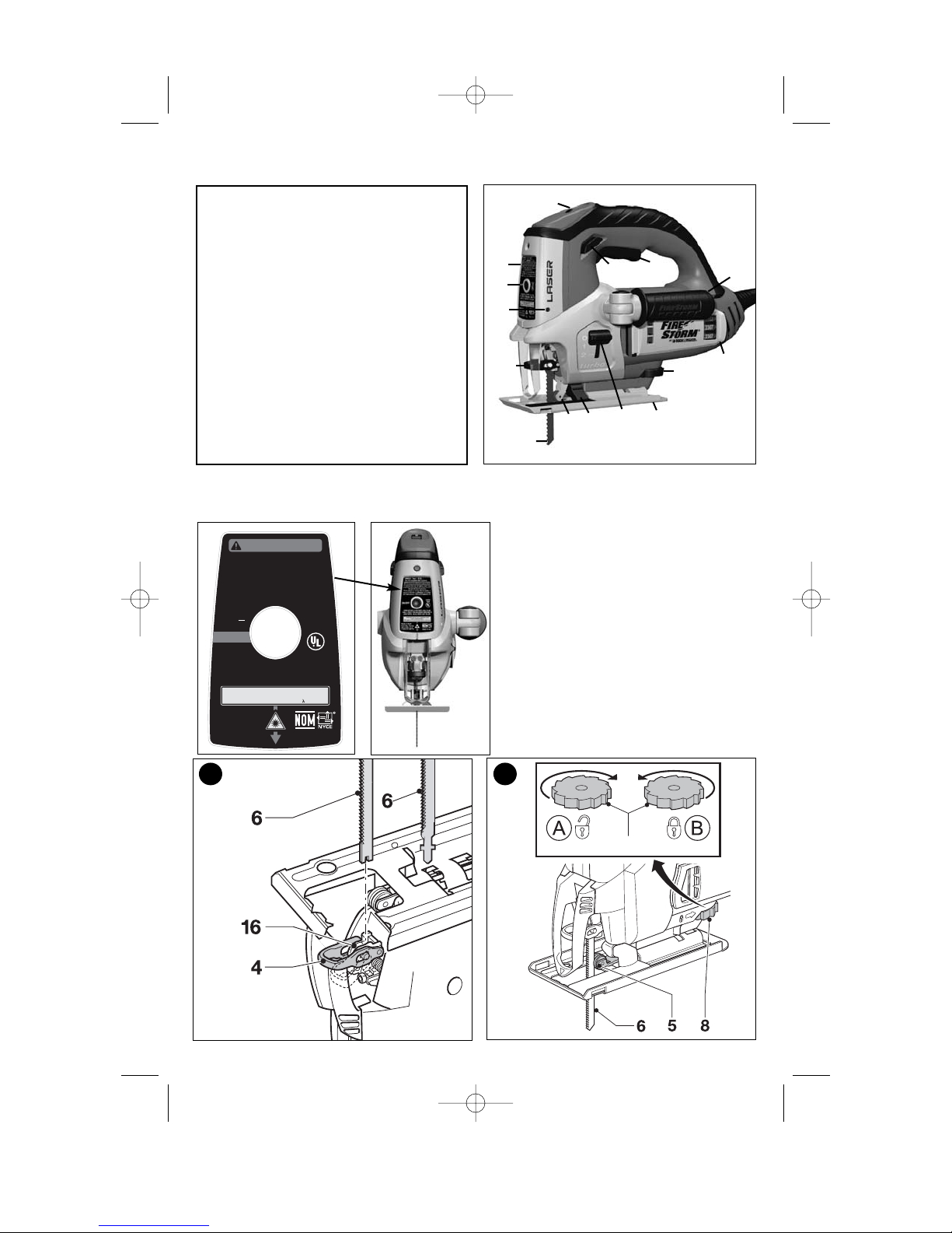
Features - FS6000JSL
1. Jig Saw On/Off switch
2. Lock-on button
3. Variable speed control knob
4. Saw blade clamp lever
5. Saw blade support roller
6. Saw blade
7. Shoe plate
8. Shoe plate locking knob
9. Saw blade storage compartment
10. Laser
11. Laser On/Off button
12. Laser adjustment screw
13. Finish Control System orbital selector
14. Folding Handle
15. Dust blower
1
13
11
9
8
7
6
5
4
3
2
12
14
15
10
90501323 FS6000JSL 4/5/06 11:06 AM Page 5
WARNING/
ADVERTENCIA
To reduce the risk of injury, user
must read and understand instruction
manual. Use (2) AA size batteries.
Para reducir el riesgo de lesiones, el
usuario debe leer y entender el manual
de instrucciones. Utilice (2) baterías AA
588808-01
Type 1
3V DC ---
ON/OFF
COMPLIES WITH 21CFR PARTS 1040.10 AND
1040.11 EXCEPT FOR DEVIATIONS PURSUANT TO
LASER NOTICE NO.50, DATED JULY 26,2001.
LASER RADIATION DO NOT STARE INTO BEAM
CLASS 2 LASER PRODUCT
PER EN60825-1:11994+AII+A2 Pmax- 2.8mW,
Black & Decker
(U.S.) Inc., Towson,
MD 21286 U.S.A.
1-800-54-HOW-TO
Use with
compatible
B&D Jig
Saws.
LISTED 406A
=633-670nm
Made in China
Page 6

6
F
D
C
E
C1
90501323 FS6000JSL 4/5/06 11:06 AM Page 6
OFF
ON
Page 7

7
Motor
Be sure your power supply agrees with nameplate marking. 120 Volts AC only means
your tool will operate on standard 60 Hz household power. Do not operate AC tools on
DC. A rating of 120 volts AC/DC means that you tool will operate on standard 60 Hz AC
or DC power. This information is printed on the nameplate. Lower voltage will cause loss
of power and can result in over-heating. All Black & Decker tools are factory-tested; if this
tool does not operate, check the power supply.
SAVE THESE INSTRUCTIONS
ASSEMBLY -
WARNING: Sharp blade. To prevent accidental operation, make sure that the
tool is switched off and unplugged and that the saw blade has stopped before
performing the following operations. Failure to do this could result in serious personal
injury. Used saw blades can be hot.
INSERTING THE SAW BLADE (FIG. A)
- Hold the saw blade (6) as shown, with teeth facing forward.
- Push the lever (4) downwards.
- Insert the shank of the saw blade into the blade holder (16) as far as it will go.
- Release the lever.
- Adjust the blade support roller as described below.
ADJUSTING THE BLADE SUPPORT ROLLER (FIG. B)
After inserting the blade, you need to adjust the blade support roller (5).
- Turn the locking knob (8) in direction A.
- Slide the blade support roller against the rear of the blade. The blade must locate in the
central recess of the roller.
- Turn the locking knob (8) in direction B to lock the shoe plate in place.
ATTACHING AND REMOVING THE HANDLE (FIG. C, C1)
The handle is keyed and can only be inserted one way.
To attach handle:
- Insert handle shaft (17) into the handle recess (18) on either side of saw and push until
keyed section slides completely into recess.
- With keyed section completely in recess, twist handle 1/4 turn clockwise.
To remove handle:
- Twist handle 1/4 turn counterclockwise and pull straight out.
To fold handle:
- Press the release button (19) and fold the handle back against the side of the saw until it
locks in place. To unfold, press the release button again and swing the handle out until it
locks into place.
OPERATING THE JIG SAW
WARNING: Laceration Hazard. To prevent loss of control, never use the tool
when the saw shoe is loose or removed. Failure to do this could result in serious
personal injury.
ADJUSTING THE SHOE PLATE FOR BEVEL CUTS (FIG. D)
The shoe plate can be set to a left or right bevel angle of up to 45°.
- Turn the locking knob (8) in direction A to release the shoe plate (6).
- Pull the shoe plate (7) backwards and set it to the required angle. You can use the scale
or a protractor to check the angle.
- Turn the locking knob (8) in direction B to lock the shoe plate in place.
To reset the shoe plate for straight cuts:
- Turn the locking knob (8) in direction A to release the shoe plate (7).
- Pull the shoe plate backwards and set it to an angle of approximately 0.
- Push the shoe plate forward.
- Turn the locking knob (8) in direction B to lock the shoe plate in place. Make sure that the
shoe plate is supported by the guide ribs.
90501323 FS6000JSL 4/5/06 11:06 AM Page 7
Page 8

8
VARIABLE SPEED CONTROL
- Set the variable speed control knob (3) to the required speed range. Use a high speed
for wood, medium speed for aluminum and PVC and low speed for metals other then
aluminum.
FINISH CONTROL SYSTEM ORBITAL SELECTOR
- For fast and efficient straight cuts in wood, set the selector (13) to the number “2”.
- For accurate straight and curve cutting and a smooth surface finish, set the turbo
selector (13) to the number “1”.
- Set turbo orbital action selector (13) to the number “0” position for non-orbital cutting/
metal cutting.
SWITCHING ON AND OFF
- To switch the tool on, press the switch (1). The tool speed depends on the variable speed
control knob (3) setting.
- For continuous operation, press the lock-on button (2) and release the switch.
- To switch the tool off, release the switch. To switch the tool off, when in continuous
operation, press the switch once more and release it.
Operating the Laser
Your saw is equipped with a laser which is turned on and off separately from the jig saw.
WARNING: NEVER aim the beam at a workpiece with a reflective surface. Bright
shiny reflective sheet steel or similar reflective surfaces are not recommended for laser
use. Reflective surfaces could direct the beam back toward the operator.
DANGER: LASER RADIATION. AVOID DIRECT EYE EXPOSURE. Do not stare into
the laser light source. Never aim light at another person or object other than the
workpiece. Laser light can damage your eyes.
WARNING: DO NOT use tinted glasses to enhance the laser light. Tinted glasses
will reduce overall vision for the application and interfere with the normal operation of the
tool.
INSTALLING THE BATTERIES (FIG. E)
Detach the laser from the jig saw by removing the screw (20) and pulling laser (10)
forward. Insert 2 fresh 1.5 volt AAAbatteries making sure to match (+) and (-) terminals
correctly. Reattach the laser.
WARNING: Batteries can explode, or leak, and can cause injury or fire. To reduce
this risk:
• Carefully follow all instructions and warnings on the battery label and package.
• Always insert batteries correctly with regard to polarity (+ and -), marked on the battery
and the equipment.
• Do not short battery terminals.
• Do not charge batteries.
• Do not mix old and new batteries. Replace all of them at the same time with new batteries
of the same brand and type.
• Remove dead batteries immediately and dispose of per local codes.
• Do not dispose of batteries in fire.
• Keep batteries out of reach of children.
• Remove batteries if the device will not be used for several months.
“Transporting batteries can possibly cause fires if the battery terminals inadvertently
come in contact with conductive materials such as keys, coins, hand tools and the like.
The US Department of Transportation Hazardous Material Regulations (HMR) actually
prohibit transporting batteries in commerce or on airplanes (i.e. packed in suitcases
and carryon luggage) UNLESS they are properly protected from short circuits. So
when transporting individual batteries, make sure that the battery terminals are
protected and well insulated from materials that could contact them and cause a short
circuit.”
SWITCHING THE LASER ON AND OFF (FIG. E)
To turn the laser on, press in on the on/off button (21). To turn the laser off, press the
button a second time. The laser button is “on” when subflush to the housing, and “off”
when the laser button is flush.
90501323 FS6000JSL 4/5/06 11:06 AM Page 8
Page 9

9
ADJUSTING THE LASER SIDE TO SIDE (FIG. F)
NOTE: Laser is intended to be a cutting aid and does not guarantee a precise cut.
Use laser adjustment screw (22) to align laser line with saw blade if needed.
WARNING: Laceration Hazard: DO NOT adjust the laser when the jig saw is
plugged in.
WARNING: Laser circuit will reduce output visibility (power) of laser when overheated.
Laser may be not visible when saw is overloaded for prolonged period of time. Laser
visibility (power) will gradually return back to normal when tool cools down even if the tool
is unplugged.
WARNING: Do not leave overheated laser ON unattended. Make sure the switch is in
the OFF position as shown in the inset of figure D. Remove the batteries to cut power to
the laser.
Hints for Optimum Use
GENERAL
- Use a high speed for wood, a medium speed for aluminum and PVC and a low speed
for metals other than aluminum.
SAWING LAMINATES
As the saw blade cuts on the upward stroke, splintering may occur on the surface closest
to the shoe plate.
- Use a fine-tooth saw blade.
- Saw from the back surface of the workpiece.
- To minimize splintering, clamp a piece of scrap wood or hardboard to both sides of
the workpiece and saw through this sandwich.
SAWING METAL
- Be aware that sawing metal takes much more time than sawing wood.
- Use a saw blade suitable for sawing metal.
- When cutting thin metal, clamp a piece of scrap wood to the back surface of the
workpiece and cut through this sandwich.
- Spread a film of oil along the intended line of cut.
TROUBLESHOOTING
Problem
Possible Cause Possible
Solution
• Unit will not start. • Cord not plugged in. • Plug tool into a working
outlet.
• Circuit fuse is blown. • Replace circuit fuse.
(If the product repeatedly
causes the circuit
fuse to blow, discontinue
use immediately and
have it serviced at a Black
& Decker service center or
authorized servicer.)
• Circuit breaker is tripped. • Reset circuit breaker.
(If the product repeatedly
causes the circuit breaker
to trip, discontinue use
immediately and have it
serviced at a Black &
Decker service center or
authorized servicer.)
• Cord or switch is damaged. • Have cord or switch
replaced at Black &
Decker Service Center or
Authorized Servicer
For assistance with your product, visit our website www.blackanddecker.com for the
location of the service center nearest you or call the BLACK & DECKER help line at
1-800-544-6986.
90501323 FS6000JSL 4/5/06 11:06 AM Page 9
Page 10
10
MAINTENANCE
Use only mild soap and damp cloth to clean the tool. Never let any liquid get inside the
tool; never immerse any part of the tool into a liquid.
IMPORTANT: To assure product SAFETY and RELIABILITY, repairs, maintenance and
adjustment (other than those listed in this manual) should be performed by authorized
service centers or other qualified service personnel, always using identical replacement
parts.
ACCESSORIES
Recommended accessories for use with your tool are available from your local dealer or
authorized service center. If you need assistance regarding accessories, please call:
1-800-544-6986.
WARNING: The use of any accessory not recommended for use with this tool could be
hazardous.
SERVICE INFORMATION
All Black & Decker Service Centers are staffed with trained personnel to provide
customers with efficient and reliable power tool service. Whether you need technical
advice, repair, or genuine factory replacement parts, contact the Black & Decker location
nearest you. To find your local service location, refer to the yellow page directory under
"Tools—Electric" or call: 1-800-544-6986 or visit www.blackanddecker.com
FULL TWO-YEAR HOME USE WARRANTY
Black & Decker (U.S.) Inc. warrants this product for two years against any defects in
material or workmanship. The defective product will be replaced or repaired at no charge
in either of two ways.
The first, which will result in exchanges only, is to return the product to the retailer from
whom it was purchased (provided that the store is a participating retailer). Returns should
be made within the time period of the retailer’s policy for exchanges (usually 30 to 90 days
after the sale). Proof of purchase may be required. Please check with the retailer for their
specific return policy regarding returns that are beyond the time set for exchanges.
The second option is to take or send the product (prepaid) to a Black & Decker owned or
authorized Service Center for repair or replacement at our option. Proof of purchase may
be required. Black & Decker owned and authorized Service Centers are listed under
"Tools-Electric" in the yellow pages of the phone directory and on our website
www.blackanddecker.com.
This warranty does not apply to accessories. This warranty gives you specific legal rights
and you may have other rights which vary from state to state. Should you have any
questions, contact the manager of your nearest Black & Decker Service Center. This
product is not intended for commercial use.
FREE WARNING LABEL REPLACEMENT: If your warning labels become illegible or are
missing, call 1-800-544-6986 for a free replacement.
Special Warranty Note to Contractors:
FIRESTORMTMbranded products are offered as high end consumer home use tools and
carry a HOME USE WARRANTY. These tools are designed, manufactured and tested to
meet or exceed the needs of the do-it-yourselfer in the execution of projects and repairs in
and around the home. With proper use they will provide the home owner with step up
power and performance well beyond their two year warranty. However, if you use tools for
a living and use FIRESTORM
TM
branded products or any of Black & Decker’s other
Consumer Home Use tools ON THE JOBSITE you should know that they CANNOT BE
COVERED UNDER OUR WARRANTY.
See ‘Tools-Electric’
– Yellow Pages –
for Service & Sales
Imported by
Black & Decker (U.S.) Inc.,
701 E. Joppa Rd.
Towson, MD 21286 U.S.A.
TECHNICAL SPECIFICATIONS OF LASER:
Laser diode wavelength: 633-670nm (red color)
Laser Class: Class II
Working Range: Up to 6 inches (152mm) line span (depends on light
conditions)
Batteries: 2 AAA alkaline (included)
Voltage: 3 Volts
Operating temperature: 41°F (5°C) - 104° F (40°C)
90501323 FS6000JSL 4/5/06 11:06 AM Page 10
Page 11
11
CONSERVER CE MANUEL POUR UN USAGE ULTÉRIEUR.
AVANT DE RETOURNER CE PRODUIT POUR
QUELQUE RAISON QUE CE SOIT, COMPOSER LE
1-800-544-6986
AVANT D’APPELER, AYEZ EN MAIN LE N° DE CATALOGUE ET LE CODE DE DATE. DANS LA PLUPART
DES CAS, UN REPRÉSENTANT DE BLACK & DECKER PEUT RÉSOUDRE LE PROBLÈME PAR
TÉLÉPHONE. SI VOUS AVEZ UNE SUGGESTION OU UN COMMENTAIRE, APPELEZ-NOUS. VOS
IMPRESSIONS SONT CRUCIALES POUR BLACK & DECKER.
M
M
ERCI
ERCIDD
’
’
AAVOIR
VOIR
CHOISI
CHOISI
F
F
IREST
IREST
ORM
ORM
!
!
V
V
ISITEZ
ISITEZ
WWW
WWW
.F
.F
IREST
IREST
ORMT
ORMT
OOLS
OOLS
.
.
COM
COM
/P
/P
RODUCT
RODUCT
R
R
EGISTRA
EGISTRA
TION
TION
POUR
POUR
ENREGISTRER
ENREGISTRER
VOTRE
VOTRE
NOUVEAU
NOUVEAU
PRODUIT
PRODUIT
.
.
N° de catalogue
FS6000JSL
SSSScccciiiieeee ssssaaaauuuutttteeeeuuuusssseeee àààà ffffoooonnnnccccttttiiiioooonnnnnnnneeeemmmmeeeennnntt
tt
oooorrrrbbbbiiiittttaaaallll aaaavvvveeeecccc llllaaaasssseeeerr
rr
MODE D’EMPLOI
90501323 FS6000JSL 4/5/06 11:06 AM Page 11
Page 12

12
RÈGLES DE SÉCURITÉ GÉNÉRALES
AVERTISSEMENT! Lire toutes les directives. Tout manquement aux directives
suivantes pose des risques de choc électrique, d’incendie et/ou de blessure
grave. Le terme « outil électrique » dans tous les avertissements ci-après se
rapporte à votre outil électrique à alimentation sur secteur (avec fil) ou par piles
(sans fil).
AVERTISSEMENT : Afin de réduire le risque de blessures, l’utilisateur doit
lire le mode d’emploi.
CONSERVER CES DIRECTIVES
1) SÉCURITÉ DU LIEU DE TRAVAIL
a) Tenir la zone de travail propre et bien éclairée. Les endroits sombres sont souvent
des causes d'accidents.
b) Ne pas faire fonctionner d’outils électriques dans un milieu déflagrant, soit en
présence de liquides inflammables, de gaz ou de poussière. Les outils
électriques produisent des étincelles qui peuvent enflammer la poussière ou les
vapeurs.
c) Éloigner les enfants et les curieux au moment d’utiliser un outil électrique. Une
distraction pourrait vous en faire perdre la maîtrise.
2) SÉCURITÉ EN MATIÈRE D’ÉLECTRICITÉ
a) Les fiches des outils électriques doivent correspondre à la prise. Ne jamais
modifier la fiche en aucune façon. Ne jamais utiliser de fiche d’adaptation avec un
outil électrique mis à la terre. Le risque de choc électrique sera réduit par l’utilisation
de fiches non modifiées correspondant à la prise.
b) Éviter tout contact physique avec des surfaces mises à la terre comme des
tuyaux, des radiateurs, des cuisinières et des réfrigérateurs. Le risque de choc
électrique est plus élevé si votre corps est mis à la terre.
c) Ne pas exposer les outils électriques à la pluie ou à d'autres conditions où il
pourrait être mouillé. La pénétration de l’eau dans un outil électrique augmente le
risque de choc électrique.
d) Ne pas utiliser abusivement le cordon d’alimentation. Ne jamais utiliser le
cordon pour transporter, tirer ou débrancher un outil électrique. Tenir le cordon
éloigné de la chaleur, de l’huile, des bords tranchants ou des pièces mobiles.
Les cordons endommagés ou emmêlés augmentent les risques de choc électrique.
Remplacer ou réparer les cordons endommagés. S’assurer que la rallonge est en
bon état. Utiliser uniquement une rallonge à 3 fils pourvue d'une fiche de mise à la
terre à 3 lames et une prise à 3 fentes correspondant à la fiche.
e) Pour l’utilisation d’un outil électrique à l’extérieur, se servir d’une rallonge
convenant à une telle utilisation. L’utilisation d’une rallonge conçue pour l’extérieur
réduit les risques de choc électrique. Lorsque qu’une rallonge électrique est utilisée,
s’assurer d’en utiliser une de calibre suffisamment élevé pour assurer le transport du
courant nécessaire au fonctionnement de votre appareil. Un cordon de calibre
inférieur causera une chute de tension de ligne et donc une perte de puissance et
une surchauffe. Le tableau suivant indique le calibre approprié à utiliser selon la
longueur du cordon et l’intensité nominale de la plaque signalétique. En cas de
doute, utiliser le calibre suivant le plus gros. Plus le numéro de calibre est petit, plus
le cordon est lourd.
Calibre minimum pour les rallonges
Volts Longueur totale du cordon en pieds
120 V 0-25 26-50 51-100 101-150
240 V 0-50 51-100 101-200 201-300
Intensité nominale
Plus Pas plus Calibrage américain normalisé des fils (AWG)
de de
0 - 6 18 16 16 14
6 - 10 18 16 14 12
10 - 12 16 16 14 12
12 - 16 14 12 Non recommandé
90501323 FS6000JSL 4/5/06 11:06 AM Page 12
Page 13

13
3) SÉCURITÉ PERSONNELLE
a) Être vigilant, surveiller le travail effectué et faire preuve de jugement lorsqu’un
outil électrique est utilisé. Ne pas utiliser d’outil électrique en cas de fatigue ou
sous l’influence de drogues, d’alcool ou de médicaments. Un moment
d’inattention, durant l’utilisation d’un outil électrique, peut se solder par des blessures
graves.
b) Utiliser un équipement de sécurité. Toujours porter une protection oculaire.
L’utilisation d’un équipement de sécurité comme un masque anti-poussières, des
chaussures antidérapantes, un casque de sécurité ou des protecteurs auditifs
lorsque la situation le requiert réduira les risques de blessures corporelles.
c) Attention de ne pas mettre en marche l’outil accidentellement. S’assurer que
l’interrupteur est en position d’arrêt avant tout branchement. Transporter un
outil électrique alors que le doigt est sur l’interrupteur ou brancher un outil électrique
alors que l’interrupteur est en position de marche risque de causer un accident.
d) Retirer toute clé de réglage ou clé standard avant de démarrer l’outil. Une clé
standard ou une clé de réglage attachée à une partie pivotante peut causer des
blessures.
e) Ne pas trop tendre les bras. Conserver son équilibre en tout temps. Cela
permet de mieux maîtriser l’outil électrique dans les situations imprévues.
f) S’habiller de manière appropriée. Ne pas porter de vêtements amples ni de
bijoux. Maintenir cheveux, vêtements et gants éloignés des pièces mobiles.
Les vêtements amples, bijoux ou cheveux longs pourraient s'enchevêtrer dans les
pièces mobiles. Se tenir éloigné des évents puisque ces derniers pourraient
camoufler des pièces mobiles.
g) Si des composants sont fournis pour le raccordement de dispositifs de
dépoussiérage et de ramassage, s’assurer que ceux-ci sont bien raccordés et
utilisés. L’utilisation de ces dispositifs peut réduire les risques engendrés par les
poussières.
4) UTILISATION ET ENTRETIEN D’UN OUTIL ÉLECTRIQUE
a) Ne pas forcer un outil électrique. Utiliser l’outil électrique approprié à
l’application. L’outil électrique approprié effectuera un meilleur travail, de façon plus
sûre et à la vitesse pour laquelle il a été conçu.
b) Ne pas utiliser un outil électrique dont l’interrupteur est défectueux. Tout outil
électrique dont l’interrupteur est défectueux est dangereux et doit être réparé.
c) Débrancher la fiche du secteur ou le bloc-piles de l’outil électrique avant de
faire tout réglage ou changement d’accessoire, ou avant de ranger l’outil
électrique. Ces mesures préventives réduisent les risques de démarrage accidentel
de l’outil électrique.
d) Ranger les outils électriques hors de la portée des enfants, et ne permettre à
aucune personne n’étant pas familière avec un outil électrique (ou son manuel
d’instruction) d’utiliser ce dernier. Les outils électriques deviennent dangereux
entre les mains d’utilisateurs inexpérimentés.
e) Entretenir les outils électriques. Vérifier les pièces mobiles pour s’assurer
qu’elles sont bien alignées et tournent librement, qu’elles sont en bon état et
ne sont affectées par aucun trouble susceptible de nuire au bon
fonctionnement de l’outil électrique. En cas de dommage, faire réparer l’outil
électrique avant toute nouvelle utilisation. Beaucoup d’accidents sont causés par des
outils électriques mal entretenus.
f) S’assurer que les outils de coupe sont aiguisés et propres. Les outils de coupe
bien entretenus et affûtés sont moins susceptibles de se coincer et sont plus faciles
à contrôler.
g) Utiliser l’outil électrique, les accessoires, les mèches, etc., conformément aux
présentes directives et suivant la manière prévue pour ce type particulier
d’outil électrique, en tenant compte des conditions de travail et du travail à
effectuer. L’utilisation d’un outil électrique pour toute opération autre que celle pour
laquelle il a été conçu est dangereuse.
90501323 FS6000JSL 4/5/06 11:06 AM Page 13
Page 14

5) RÉPARATION
a) Faire réparer l’outil électrique par un réparateur professionnel en n’utilisant
que des pièces de rechange identiques. Cela permettra de maintenir une
utilisation sécuritaire de l’outil électrique.
b) S’il faut remplacer le cordon d’alimentation, ceci doit être fait par le fabricant ou
son agent pour éviter tout risque d’accident.
Règles de sécurité spécifiques
a) Tenir l’outil par sa surface de prise isolée dans une situation où l’outil de
coupe peut entrer en contact avec un câblage dissimulé ou avec son propre
cordon d’alimentation. Tout contact avec un fil « sous tension » mettra « sous
tension » les pièces métalliques de l’outil et électrocutera l’opérateur de l’outil.
b) Tenir les mains éloignées de la zone de découpe. Ne jamais mettre la main sous
le matériau pour quelque raison que ce soit. Tenir la partie avant de la scie par sa
zone de prise profilée. Ne pas mettre les doigts ou le pouce à proximité de la scie
alternative et du mécanisme de serrage de la lame. Ne pas stabiliser la scie en
saisissant la semelle.
c) Utiliser des brides de fixation ou un autre dispositif de fixation permettant de
soutenir et de retenir la pièce sur une plate-forme stable. Tenir la pièce avec la
main ou contre son corps est instable et risque d’entraîner une perte de maîtrise de
l’outil.
d) Maintenir les lames affûtées. Les lames émoussées peuvent faire zigzaguer la
scie ou la bloquer sous la pression.
e) Au moment de couper un tuyau ou un conduit, s’assurer qu’ils sont exempts
d’eau, de câblage électrique, etc.
AVERTISSEMENT : Certains outils électriques, tels que les sableuses, les scies,
les meules, les perceuses ou certains autres outils de construction, peuvent
produire de la poussière contenant des produits chimiques susceptibles
d’entraîner le cancer, des malformations congénitales ou pouvant être nocifs pour
le système reproductif. Parmi ces produits chimiques, on retrouve :
• le plomb dans les peintures à base de plomb,
• la silice cristalline dans les briques et le ciment et autres produits de maçonnerie,
• l’arsenic et le chrome dans le bois de sciage ayant subi un traitement
chimique (comme l’arséniate de cuivre et de chrome).
Le risque associé à de telles expositions varie selon la fréquence avec laquelle on
effectue ces travaux. Pour réduire l’exposition à de tels produits, il faut travailler dans un
endroit bien aéré et utiliser le matériel de sécurité approprié, tel un masque
anti-pous sières spécialement conçu pour filtrer les particules microscopiques.
• Éviter tout contact prolongé avec la poussière soulevée par cet outil ou autres
outils électriques. Porter des vêtements de protection et nettoyer les parties
exposées du corps à l’eau savonneuse. S’assurer de bien se protéger afin d’éviter
d’absorber par la bouche, les yeux ou la peau des produits chimiques nocifs.
AVERTISSEMENT : Cet outil peut produire et répandre de la poussière
susceptible de causer des dommages sérieux et permanents au système
respiratoire. Toujours utiliser un appareil respiratoire anti-poussières approprié approuvé
par le NIOSH ou l’OSHA. Diriger les particules dans le sens opposé du visage et du corps.
MISE EN GARDE : Porter un dispositif approprié de protection de l’ouïe lors de
l’utilisation du produit. Dans certaines conditions et durées d’utilisation, le produit peut
émettre un niveau de bruit provoquant la perte de l’ouïe.
L’étiquette de l’outil peut comporter les symboles suivants.
V ................volts A ..............ampères
Hz ..............hertz W ..............watts
min ..............minutes ............courant alternatif
............courant continu
n
o..............sous vide
..............
Construction de classe II
..............borne de mise à la minute
..............symbole d´avertissement .../min........tours à la minute
mW ............milliwatts nm ............longueur d’onde en nanomètre
II ......................Laser classe II
14
90501323 FS6000JSL 4/5/06 11:06 AM Page 14
Page 15

15
DIRECTIVES DE SÉCURITÉ POUR LASERS
DANGER : rayonnement laser; éviter tout contact direct avec les yeux, des
blessures graves aux yeux peuvent en résulter.
• Ne pas utiliser d’instruments optiques comme un télescope ou un théodolite pour
observer le faisceau laser.
• Positionner le laser de telle sorte à éviter tout contact accidentel avec les yeux.
• Ne pas utiliser le laser près des enfants et ne pas laisser les enfants utiliser le laser.
• Ne pas démonter l’appareil. Toute modification du produit peut accroître le risque de
rayonnement laser.
AVERTISSEMENT : l’utilisation de commandes ou de réglages ou l’exécution de
procédures autres que celles précisées dans la présente peut entraîner une exposition
dangereuse au rayonnement laser.
• Ne pas ajuster le laser sur l’unité de sciage lorsque la scie est branchée.
• Ne pas faire fonctionner l’outil dans un environnement explosif, soit en présence de
liquides inflammables, de gaz ou de poussière.
• Utiliser uniquement l’outil avec les piles spécifiquement conçues pour le laser. L’utilisation
de toute autre pile peut provoquer un incendie.
• Ranger le produit inutilisé hors de la portée des enfants et des personnes sans
expérience. Les lasers sont des appareils dangereux lorsqu’ils sont entre les mains
d’utilisateurs inexpérimentés.
• N’utiliser que les accessoires conseillés par le fabricant pour le modèle de votre outil. Les
accessoires adaptés à un laser donné peuvent être dangereux lorsqu’ils sont utilisés
avec un autre laser.
• Les réparations et l’entretien de l’outil DOIVENT uniquement être effectués par un
établissement de réparation professionnel. Toute réparation réalisée par du personnel
non qualifié pourrait entraîner des blessures graves.
• Ne pas enlever ni altérer les étiquettes de mises en garde. Enlever les étiquettes accroît
le risque d’exposition au rayonnement.
• Pour un usage intérieur seulement.
• Ce produit est conçu pour une utilisation dans une plage de températures variant de 5° C
(41° F) à 40° C (104° F).
Caractéristiques du modèle
FS6000JSL
1. Interrupteur marche/arrêt de la scie
sauteuse
2. Bouton de verrouillage
3. Molette de contrôle de vitesses
variables
4. Levier de serrage de la lame de la scie
5. Roulette d’appui de la lame de la scie
6. Lame de scie
7. Plaque de la semelle
8. Molette de blocage de la plaque de la
semelle
9. Compartiment de rangement pour
lames
10. Laser
11. Bouton Marche/Arrêt du laser
12. Vis de réglage du laser
13. Sélecteur du système de contrôle du
fini à mouvement orbital
14. Poignée pliante
15. Dépoussiéreur
1
13
11
9
8
7
6
5
4
3
2
12
14
15
10
90501323 FS6000JSL 4/5/06 11:06 AM Page 15
Page 16

16
LASER RADIA TION DO NOT ST ARE INTO BEAM
CLASS 2 LAS ER PRODUCT
PER EN60825-1:11994+AII+A 2 Pmax- 2.8mW,
=633-670nm
Pour plus de commodité et de sécurité, les étiquettes suivantes sont apposées sur le laser.
A
8
B
C
C1
90501323 FS6000JSL 4/5/06 11:06 AM Page 16
WARNING/
must read and understand instruction
Para reducir el riesgo de lesiones, el
usuario debe leer y entender el manual
de instrucciones. Utilice (2) baterías AA
588808-01
Type 1
3V DC ---
ON/OFF
COMPLIES WITH 21CFR PARTS 1040.10 AND
1040.11 EXCEPT FOR DEVIATIONS PURSUANT TO
LASER NOTICE NO.50, DATED JULY 26,2001.
PER EN60825-1:11994+AII+A2 Pmax- 2.8mW,
Black & Decker
(U.S.) Inc., Towson,
MD 21286 U.S.A.
1-800-54-HOW-TO
ADVERTENCIA
To reduce the risk of injury, user
manual. Use (2) AA size batteries.
Use with
compatible
B&D Jig
Saws.
LISTED 406A
LASER RADIATION DO NOT STARE INTO BEAM
CLASS 2 LASER PRODUCT
=633-670nm
Made in China
Page 17

17
Moteur
S’assurer que le bloc d’alimentation est compatible avec l’inscription de la plaque
signalétique. L’inscription 120 volts c.a. seulement indique que l’outil fonctionnera sur
une alimentation domestique standard de 60 Hz. Ne pas faire fonctionner des outils à
courant alternatif (c.a.) sur un courant continu (c.c.). Un régime nominal de 120 volts
c.a./c.c. signifie que l’outil fonctionnera avec une alimentation standard 60 Hz c.a. ou
c.c. Ce renseignement figure sur la plaque signalétique. Une plus faible tension
entraînera une baisse de régime, ce qui peut entraîner une surchauffe. Tous les outils
Black & Decker sont testés en usine; si cet outil ne fonctionne pas, vérifier le bloc
d’alimentation.
CONSERVER CES DIRECTIVES
ASSEMBLAGE
AVERTISSEMENT : lame tranchante. Pour empêcher tout démarrage inopiné,
éteindre l’outil et le débrancher. S’assurer que la lame soit immobile avant
d’effectuer les opérations suivantes. Négliger d’agir ainsi risque de causer des
blessures corporelles graves. Les lames de scies utilisées peuvent être chaudes.
INSERTION DE LA LAME DE SCIE (FIG. A)
- Tenir la lame de scie (6) comme indiqué avec les dents vers l’avant de l’outil.
- Abaisser le levier de serrage (4).
- Insérer l’emmanchement de la lame dans le porte-lame (16) aussi loin que possible.
- Relâcher le levier.
- Ajuster la roulette d’appui de la lame comme suit.
D
E
F
90501323 FS6000JSL 4/5/06 11:06 AM Page 17
OFF
ON
Page 18

18
AJUSTEMENT DE LA ROULETTE D’APPUI DE LA LAME (FIG. B)
Une fois la lame insérée, effectuer l’ajustement de la roulette d’appui de la lame (5).
- Tourner la molette de blocage (8) dans la direction A.
- Coulisser la roulette d’appui contre l’arrière de la lame. Celle-ci doit se loger dans la
rainure-guide centrale de la roulette.
- Tourner la molette de blocage (8) dans la direction B pour verrouiller la plaque de la
semelle en position.
FIXATION ET RETRAIT DE LA POIGNÉE (FIG. C, C1)
La poignée se fixe par clavette et ne s’insère que d’une façon.
Fixation de la poignée :
- Insérer la tige de la poignée (17) dans la gorge (18) d’un côté ou de l’autre de la scie et
la tourner jusqu’à ce que les sections clavetées glissent entièrement dans la gorge.
- Une fois la poignée bien insérée dans la gorge, la tourner d’un quart de tour en sens
horaire.
Retrait de la poignée :
- Tourner la poignée d’un quart de trou en sens antihoraire et tirer droit.
Pliage de la poignée :
-Enfoncer le bouton de dégagement (19) et replier la poignée contre le corps de la scie
jusqu’à ce qu’elle se bloque en position. Pour la déplier, enfoncer de nouveau le bouton
de dégagement et déployer la poignée jusqu’à ce qu’elle se bloque en position.
UTILISATION DE LA SCIE SAUTEUSE
AVERTISSEMENT : risque de lacération. Anticiper une perte de contrôle, ne
jamais utiliser la scie sans la semelle ou avec une semelle lâche. L’inobservation
de ces mesures risque d’entraîner des blessures corporelles graves.
RÉGLAGE DE LA PLAQUE DE LA SEMELLE POUR DES COUPES BISEAUTÉES
(FIG. D)
La plaque de la semelle s’incline à gauche ou à droite pour une coupe en biseau jusqu’à
45°.
- Tourner la molette de blocage (8) dans la direction A pour dégager la plaque de la
semelle (6).
- Coulisser la plaque de la semelle (7) vers l’arrière et la régler à l’angle recherché. Le cas
échéant, utiliser une échelle ou un rapporteur d’angle pour vérifier l’angle obtenu.
- Tourner la molette de blocage (8) dans la direction B pour verrouiller la plaque de la
semelle en position.
Pour régler la plaque de la semelle pour des coupes droites :
- Tourner la molette de blocage (8) dans la direction A pour dégager la plaque de la
semelle (7).
- Coulisser la plaque de la semelle vers l’arrière et la régler à un angle d’environ zéro.
- Coulisser la plaque vers l’avant.
- Tourner la molette de blocage (8) dans la direction B pour verrouiller la plaque de la
semelle en position. S’assurer que la plaque de la semelle soit appuyée sur les filets de
positionnement.
COMMANDE DE LA VITESSE VARIABLE
- Régler la molette de contrôle de la vitesse variable (3) à la vitesse exigée. Utiliser une
vitesse élevée pour le bois, une vitesse moyenne pour l’aluminium et le plastique PVC et
la vitesse lente pour les métaux autres que l’aluminium.
SÉLECTEUR DU SYSTÈME DE CONTRÔLE DU FINI À MOUVEMENT ORBITAL
- Pour des coupes droites rapides et efficaces dans le bois, régler le sélecteur (13) à
«2».
- Pour des coupes droites et incurvées précises et une surface à fini lisse, régler le
sélecteur turbo (13) à « 1 ».
- Régler le sélecteur de mouvement orbital turbo (13) à « 0 » pour une coupe sans
mouvement orbital ou pour la coupe de métaux.
MISE EN MARCHE ET ARRÊT
- Pour mettre la scie en marche, appuyer sur l’interrupteur (1). Le régime de l’outil est lié
au réglage de la molette de contrôle de vitesse variable (3).
- Pour un fonctionnement continu, appuyer sur le bouton de verrouillage (2) et relâcher
l’interrupteur marche/arrêt.
90501323 FS6000JSL 4/5/06 11:06 AM Page 18
Page 19

19
- Pour éteindre l’outil, relâcher l’interrupteur. Pour mettre l’outil hors tension en mode de
fonctionnement continu, appuyer sur l’interrupteur marche/arrêt une fois puis le relâcher.
UTILISATION DU LASER
Votre scie est dotée d’un laser qui s’allume et s’éteint indépendamment de la scie
sauteuse.
AVERTISSEMENT : NE JAMAIS diriger le faisceau sur une pièce comportant une
surface réfléchissante. BLes feuilles d’acier brillant et réfléchissant et les autres surfaces
réfléchissantes similaires ne sont pas recommandées pour une utilisation avec le laser.
Les surfaces réfléchissantes peuvent rediriger le faisceau vers l’opérateur.
DANGER : RAYONNEMENT LASER. ÉVITER TOUT CONTACT DIRECT AVEC LES
YEUX. Ne pas regarder vers la source de lumière du laser. Ne jamais diriger la
lumière vers une autre personne ou vers tout autre objet que votre ouvrage. La
lumière du laser peut endommager les yeux.
AVERTISSEMENT : NE PAS UTILISER de verres teintés pour augmenter la
lumière du laser. Les verres teintés réduisent la vision globale de l’application et
interfèrent avec le fonctionnement normal de l’outil.
INSERTION DES PILES (FIG. E)
Détacher le laser de la scie sauteuse en retirant la vis (20) puis tirer le laser (10) vers
l’avant. Insérer deux nouvelles piles alcalines AAAde 1,5 volts et s’assurer de bien faire
correspondre les bornes (+) et (-). Fixer de nouveau le laser.
AVERTISSEMENT : les piles peuvent exploser ou couler et provoquer des
blessures ou un incendie. Pour réduire ce risque :
• Suivre attentivement toutes les directives et avertissements figurant sur l’étiquette des
piles et de l’emballage de l’appareil.
• Toujours insérer les piles selon la polarité correcte (+ et -), comme indiqué sur les piles
et le matériel.
• Ne pas créer de court-circuit dans les bornes des piles.
• Ne pas charger les piles.
• Ne pas mélanger piles neuves et usagées. Les remplacer toutes en même temps par
des piles neuves de la même marque et du même type.
• Retirer immédiatement les piles déchargées et les éliminer en fonction de la
réglementation locale en vigueur.
• Ne pas jeter les piles dans un feu.
• Garder les piles hors de la portée des enfants.
• Retirer les piles si l’appareil n’est pas utilisé pendant plusieurs mois.
Le transport des piles peut causer un incendie si les bornes des piles entrent en contact
involontairement avec des matières conductrices comme des clés, de la monnaie, des
outils manuels et d’autres éléments semblables. La Hazardous Material Regulation du
département américain des transports interdit en fait le transport des piles pour le
commerce ou dans les avions (par ex. : piles emballées dans des valises et des
bagages à main) À MOINS qu’elles soient bien protégées contre les courts-circuits. Pour
le transport de piles individuelles, s’assurer que les bornes sont protégées et bien isolées
contre toute matière pouvant entrer en contact avec elles et causer un court-circuit.
MISE EN MARCHE/ARRÊT DU LASER (FIG. E)
Pour actionner le faisceau laser, enfoncer le bouton marche/arrêt (21) et pour l’éteindre,
l’enfoncer une seconde fois. Le bouton de mise sous tension du faisceau laser est
actionné lorsqu’il est enfoncé sous la surface du boîtier de l’outil et, hors tension, lorsqu’il
est à niveau avec le boîtier.
RÉGLAGE DU LASER POUR ACTION LATÉRALE (FIG. F)
REMARQUE : le laser est prévu pour fonctionner en tant qu’aide à la découpe et ne
garantit pas une coupe précise. Le cas échéant, utiliser la vis de réglage du laser (22)
pour aligner le faisceau avec la lame de la scie.
AVERTISSEMENT : risque de lacération. DÉBRANCHER LA SCIE SAUTEUSE
AVANT D’EFFECTUER TOUT TYPE DE RÉGLAGE DU LASER.
AVERTISSEMENT : le circuit du laser diminuera la partie visible du faisceau
(puissance) du laser lors d’une surchauffe. Le laser peut devenir invisible si la scie est
surchargée pour une période de temps prolongée. Le faisceau visible du laser
(puissance) reviendra graduellement à la normale avec le refroidissement des outils
même si ceux-ci sont débranchés.
90501323 FS6000JSL 4/5/06 11:06 AM Page 19
Page 20

20
AVERTISSEMENT : ne pas laisser un laser surchauffé à la position MARCHE sans
surveillance. S’assurer que l’interrupteur soit en position d’ARRÊT comme indiqué par
l’encart de la figure D. Retirer les piles pour couper le courant du faisceau laser.
Conseils pour une utilisation optimale
CONSEILS GÉNÉRAUX
- Utiliser une vitesse élevée pour le bois, une vitesse moyenne pour l’aluminium et le
plastique PVC et la vitesse lente pour les métaux autres que l’aluminium.
COUPE DE BOIS LAMELLÉ
La lame de la scie coupe lors de sa remonté. Il est possible d’observer des éclats sur la
surface la plus près de la plaque de la semelle.
- Utiliser une lame de scie à dents fines.
- Mettre la pièce à l’envers pour la scier.
- Pour réduire les éclats de bois, fixer une pièce de chute de bois ou de panneau
pressé des deux côtés de la pièce et couper toutes ces épaisseurs.
COUPE DU MÉTAL
- La coupe de métaux prend beaucoup plus de temps que la coupe de bois.
- Utiliser une lame compatible à la coupe de métaux.
- Lors du sciage de pièces métalliques minces, fixer une pièce de chute de bois au dos
de la surface de la pièce et couper toutes les épaisseurs.
- Étaler une fine couche d’huile sur la ligne de coupe prévue.
DÉPANNAGE
Problème Cause possible Solution possible
• L’appareil refuse • Cordon d’alimentation • Brancher l’outil dans une
de démarrer. non branché. prise qui fonctionne.
• Le fusible du circuit • Remplacer le fusible du
est grillé. circuit. (Si le produit fait
griller de façon répétée le
fusible du circuit, arrêter
immédiatement l’utilisation
du produit et le faire
réparer dans un centre de
réparation Black & Decker
ou un centre de réparation
autorisé.)
• Le disjoncteur est déclenché. • Remettre le disjoncteur à
zéro. (Si le produit fait
déclencher de façon
répétée le disjoncteur,
arrêter immédiatement
l’utilisation du produit et le
faire réparer dans un
centre de réparation Black
& Decker ou un centre de
réparation autorisé.)
• Le cordon d’alimentation • Faire remplacer le
ou l’interrupteur est endommagé. cordon ou l’interrupteur au
centre de réparation Black
& Decker ou à un centre
de réparation autorisé.
Pour obtenir de l’aide avec l’outil, consulter notre site Web www.blackanddecker.com
pour l’emplacement du centre de réparation le plus près ou communiquer avec
l’assistance BLACK & DECKER au 1-800-544-6986.
ENTRETIEN
N’utiliser qu’un détergent doux et un chiffon humide pour nettoyer l’outil. Ne jamais laisser
90501323 FS6000JSL 4/5/06 11:06 AM Page 20
Page 21

21
de liquide pénétrer dans l’outil et n’immerger aucune partie de l’outil dans un liquide.
IMPORTANT : pour garantir la SÉCURITÉ et la FIABILITÉ du produit, les réparations,
l’entretien et le réglage (autre que ceux énumérés dans ce mode d’emploi) doivent être
réalisés par un centre de réparation autorisé ou tout autre centre de réparation
professionnel, et les des pièces de rechange identiques doivent être utilisées.
Accessoires
Les accessoires recommandés pouvant être utilisés avec l’outil sont disponibles auprès
de votre distributeur local ou centre de réparation autorisé. Pour tout renseignement
concernant les accessoires, composer le : 1-800-544-6986 MISE EN GARDE :
l’utilisation de tout autre accessoire ou pièce non recommandé(e) avec cet outil pourrait
s’avérer dangereuse.
INFORMATION SUR LES RÉPARATIONS
Tous les centres de réparation Black & Decker sont dotés de personnel qualifié en
matière d’outillage électrique; ils sont donc en mesure d’offrir à leur clientèle un service
efficace et fiable. Que ce soit pour un avis technique, une réparation ou des pièces de
rechange authentiques installées en usine, communiquer avec l’établissement Black &
Decker le plus près de chez vous. Pour trouver l’établissement de réparation de votre
région, consulter le répertoire des Pages jaunes à la rubrique « Outils électriques » ou
composer le numéro suivant :
1-800-544-6986 ou consulter le site www.blackanddecker.com
GARANTIE COMPLÈTE DE DEUX ANS POUR UNE UTILISATION DOMESTIQUE
Black & Decker (É.-U.) Inc. garantit ce produit pour une durée de deux ans contre tout
défaut de matériau ou de fabrication. Le produit défectueux sera remplacé ou réparé sans
frais de l’une des deux façons suivantes :
La première façon consiste en un simple échange chez le détaillant qui l’a vendu (pourvu
qu’il s’agisse d’un détaillant participant). Tout retour doit se faire durant la période
correspondant à la politique d’échange du détaillant (habituellement, de 30 à 90 jours
après l’achat). Une preuve d’achat peut être requise. Vérifier auprès du détaillant pour
connaître sa politique concernant les retours hors de la période définie pour les échanges.
La deuxième option est d’apporter ou d’envoyer le produit (transport payé d’avance) à un
centre de réparation autorisé ou à un centre de réparation de Black & Decker pour faire
réparer ou échanger le produit, à notre discrétion. Une preuve d’achat peut être requise.
Les centres Black & Decker et les centres de service autorisés sont répertoriés dans les
pages jaunes, sous la rubrique « Outils électriques ».
Cette garantie ne s’applique pas aux accessoires. Cette garantie vous accorde des droits
légaux spécifiques et vous pourriez avoir d’autres droits qui varient d’un État ou d’une
province à l’autre. Pour toute question, communiquer avec le directeur du centre de
réparation Black & Decker le plus près de chez vous. Ce produit n’est pas destiné à un
usage commercial.
REMPLACEMENT GRATUIT DES ÉTIQUETTES D’AVERTISSEMENT : si les étiquettes
d’avertissement deviennent illisibles ou sont manquantes, composer le 1-800-544-6986
pour en obtenir le remplacement gratuit.
Remarque à l’intention des entrepreneurs concernant la garantie
spéciale
Les produits de marque FIRESTORMMCsont des outils hauts de gamme destinés aux
consommateurs et comportent une GARANTIE POUR USAGE RÉSIDENTIEL. Ces
outils sont conçus, fabriqués et mis à l’essai en vue de répondre aux besoins du
bricoleur, ou de les dépasser, lorsque ce dernier réalise des projets ou effectue des
réparations à l’intérieur ou à l’extérieur de sa résidence. Utilisés correctement, ces
outils procurent à l’utilisateur un rendement et une puissance supérieurs qui excèdent
de loin la période de garantie de deux ans. Par contre, tout outil utilisé à des fins
commerciales ou tout produit de marque FIRESTORMMCou tout autre produit Black &
Decker destiné aux consommateurs et réservé à un usage résidentiel, utilisé dans le
cadre d’une ACTIVITÉ RELIÉE AU TRAVAIL, N’EST PAS COUVERT PAR LA
PRÉSENTE GARANTIE.
90501323 FS6000JSL 4/5/06 11:06 AM Page 21
Page 22

22
Imported by / Importé par
Black & Decker Canada Inc.
100 Central Ave.
Brockville (Ontario) K6V 5W6
Voir ‘Outils électriques’
– Pages Jaunes –
pour Service et ventes
CARACTÉRISTIQUES TECHNIQUES DU LASER :
Longueur d’onde de la diode du laser : 633-670nm (couleur rouge)
Classe du laser : Classe II
Plage de fonctionnement : Jusqu’à 152 mm (6 po) de trait visible
(selon l’éclairage)
Piles : 2 AAA alcaline (incluses)
Tension : 3 Volts
Température de fonctionnement : 5 °C (41 °F) - 40 °C (104 °F)
90501323 FS6000JSL 4/5/06 11:06 AM Page 22
Page 23

23
CONSERVE ESTE MANUAL PARA FUTURAS CONSULTAS.
ANTES DE DEVOLVER ESTE PRODUCTO POR
CUALQUIER MOTIVO, LLAME AL
(55)5326-7100
ANTES DE LLAMAR, TENGA ELNÚMERO DE CATÁLOGO Y EL CÓDIGO DE FECHAPREPARADOS. EN
LA MAYORÍA DE LOS CASOS, UN REPRESENTANTE DE BLACK & DECKER PUEDE RESOLVER EL
PROBLEMA POR TELÉFONO. SI DESEAREALIZAR UNA SUGERENCIA O COMENTARIO, LLÁMENOS.
SU OPINIÓN ES FUNDAMENTALPARA BLACK & DECKER.
¡G
¡G
RACIAS
RACIAS
POR
POR
ELEGIR
ELEGIR
F
F
IREST
IREST
ORM
ORM
!
!
V
V
AAYYAAA
A
WWW
WWW
.F
.F
IREST
IREST
ORMT
ORMT
OOLS
OOLS
.
.
COM
COM
/P
/P
RODUCT
RODUCT
R
R
EGISTRA
EGISTRA
TION
TION
PPARA
ARA
REGISTRAR
REGISTRARSUSU
NUEVO
NUEVO
PRODUCT
PRODUCTOO
.
.
SSSSiiiieeeerrrrrrrraaaa ccccaaaallllaaaaddddoooorrrraaaa ddddeeee aaaacccccccciiiióóóónnnn oooorrrrbbbbiiiittttaaaallll ccccoooonn
nn
lllláááásssseeeerr
rr
Catálogo N°
FS6000JSL
MANUAL DE INSTRUCCIONES
90501323 FS6000JSL 4/5/06 11:06 AM Page 23
Page 24

Normas generales de seguridad
ADVERTENCIA: Lea todas las instrucciones. El incumplimiento de las instrucciones
enumeradas debajo puede provocar descarga eléctrica, incendio o lesiones graves. El
término “herramienta eléctrica” incluido en todas las advertencias enumeradas a
continuación hace referencia a su herramienta eléctrica operada con corriente
(alámbrica) o a su herramienta eléctrica operada con baterías (inalámbrica).
ADVERTENCIA: Para reducir el riesgo de lesiones, el usuario debe leer el manual de
instrucciones.
CONSERVE ESTAS INSTRUCCIONES
1) SEGURIDAD EN EL ÁREA DE TRABAJO
a) Mantenga el área de trabajo limpia y bien iluminada. Las áreas abarrotadas y
oscuras propician accidentes.
b) No opere herramientas eléctricas en atmósferas explosivas, como ambientes
donde se encuentran líquidos, gases o polvo inflamables. Las herramientas
eléctricas originan chispas que pueden encender el polvo o los vapores.
c) Mantenga a los niños y espectadores alejados de la herramienta eléctrica en
funcionamiento. Las distracciones pueden provocar la pérdida de control.
2) SEGURIDAD ELÉCTRICA
a) Los enchufes de la herramienta eléctrica deben adaptarse al tomacorriente.
Nunca modifique el enchufe de ninguna manera. No utilice ningún enchufe
adaptador con herramientas eléctricas con conexión a tierra. Los enchufes no
modificados y que se adaptan a los tomacorrientes reducirán el riesgo de descarga
eléctrica.
b) Evite el contacto corporal con superficies puestas a tierra, como por ejemplo
tuberías, radiadores, rangos y refrigeradores. Existe mayor riesgo de descarga
eléctrica si su cuerpo está puesto a tierra.
c) No exponga las herramientas eléctricas a la lluvia o a condiciones de
humedad. Si ingresa agua a una herramienta eléctrica, aumentará el riesgo de
descarga eléctrica.
d) No maltrate al cable. Nunca utilice el cable para transportar, tirar o
desenchufar la herramienta eléctrica. Mantenga el cable lejos del calor, aceite,
bordes afilados o piezas móviles. Los cables dañados o enredados aumentan el
riesgo de descarga eléctrica. Repare o reemplace los cables dañados. Asegúrese
de que el cableprolongador esté en buenas condiciones. Utilice solamente cables
prolongadores de 3 conductores que tengan enchufes a tierra de 3 patas y
receptáculos de tripolares que se adapten al enchufe de la herramienta.
e) Al operar una herramienta eléctrica en el exterior, utilice un cable
prolongador adecuado para tal uso. Utilice un cable adecuado para uso en
exteriores a fin de reducir el riesgo de descarga eléctrica. Cuando utilice un cable
prolongador, asegúrese de que tenga la capacidad para conducir la corriente que
su producto exige. Un cable de menor capacidad provocará una disminución en el
voltaje de la línea que producirá pérdida de potencia y sobrecalentamiento. La
siguiente tabla muestra la medida
correcta que debe utilizar según la longitud del cable y la capacidad nominal en
amperios indicada en la placa. En caso de duda, utilice el calibre inmediatamente
superior. Cuanto menor es el número de calibre, más grueso es el cable.
24
Calibre mínimo para cables prolongadores
Voltios Largo total del cable en pies
120 V 0-25 26-50 51-100 101-150
240 V 0-50 51-100 101-200 201-300
Capacidad nominal en amperios
Más de No más de Medida de conductor estadounidense
que que
0-6 18 16 16 14
6 - 10 18 16 14 12
10 - 12 16 16 14 12
12 - 16 14 12 No Recomendado
90501323 FS6000JSL 4/5/06 11:06 AM Page 24
Page 25

25
3) SEGURIDAD PERSONAL
a) Permanezca alerta, controle lo que está haciendo y utilice el sentido común
cuando emplee una herramienta eléctrica. No utilice una herramienta
eléctrica si está cansado o bajo el efecto de drogas, alcohol o
medicamentos. Un momento de descuido mientras se opera una herramienta
eléctrica podría provocar daños personales graves.
b) Use equipo de seguridad. Siempre utilice protección para los ojos. El equipo
de seguridad, como las máscaras para polvo, el calzado de seguridad
antideslizante, los cascos o la protección auditiva utilizados para condiciones
adecuadas reducirán las lesiones personales.
c) Evite el encendido por accidente. Asegúrese de que el interruptor esté en la
posición de apagado antes de enchufar la herramienta. Transportar
herramientas eléctricas con su dedo apoyado sobre el interruptor o enchufar
herramientas eléctricas con el interruptor en posición de encendido puede propiciar
accidentes.
d) Retire las clavijas de ajuste o llaves de tuercas antes de encender la
herramienta eléctrica. Una llave de tuercas o una clavija de ajuste que se deje
conectada a una pieza giratoria de la herramienta eléctrica pueden provocar
lesiones personales.
e) No se estire. Conserve el equilibrio adecuado y manténgase parado
correctamente en todo momento. Esto permite un mejor control de la
herramienta eléctrica en situaciones inesperadas.
f) Vístase apropiadamente. No use ropas holgadas ni joyas. Mantenga el
cabello, las ropas y los guantes alejados de las piezas móviles. Las ropas
holgadas, las joyas o el cabello largo pueden quedar atrapados en las piezas
móviles. Los orificios de ventilación suelen cubrir piezas móviles, por lo que también
se deben evitar.
g) Si se suministran dispositivos para la conexión de accesorios para la
recolección y extracción de polvo, asegúrese de que estén conectados y se
utilicen correctamente. El uso de estos dispositivos puede reducir los peligros
relacionados con el polvo.
4) USO Y MANTENIMIENTO DE LA HERRAMIENTA ELÉCTRICA
a) No fuerce la herramienta eléctrica. Utilice la herramienta eléctrica correcta
para el trabajo que realizará. La herramienta eléctrica correcta hará el trabajo
mejor y más seguro a la velocidad para la que fue diseñada.
b) No utilice la herramienta eléctrica si no puede encenderla o apagarla con el
interruptor. Toda herramienta eléctrica que no puede ser controlada mediante el
interruptor es peligrosa y debe ser reparada.
c) Desconecte el enchufe de la fuente de energía y/o el paquete de baterías de
la herramienta eléctrica antes de realizar ajustes, cambiar accesorios o
almacenar herramientas eléctricas. Estas medidas de seguridad preventivas
reducen el riesgo de encender la herramienta eléctrica en forma accidental.
d) Guarde las herramientas eléctricas que no están en uso fuera del alcance de
los niños y no permite que otras personas no familiarizadas con ella o con
estas instrucciones operen la herramienta. Las herramientas eléctricas son
peligrosas en las manos de usuarios no entrenados.
e) Mantenimiento de las herramientas eléctricas. Controle que no haya piezas
móviles mal alineadas o trabadas, piezas rotas y toda otra situación que
pueda afectar el funcionamiento de las herramientas eléctricas. Si encuentra
daños, haga reparar la herramienta eléctrica antes de utilizarla. Se producen
muchos accidentes a causa de las herramientas eléctricas que carecen de un
mantenimiento adecuado.
f) Mantenga las herramientas de corte afiladas y limpias. Las herramientas de
corte con mantenimiento adecuado, con los bordes de corte afilados son menos
propensas a trabarse y son más fáciles de controlar.
g) Utilice la herramienta eléctrica, los accesorios y las brocas de la herramienta,
etc. de acuerdo con estas instrucciones y de la forma prevista para el tipo de
herramienta eléctrica en particular, teniendo en cuanta las condiciones de
trabajo y el trabajo que debe realizarse. El uso de la herramienta eléctrica para
operaciones diferentes de aquéllas para las que fue diseñada puede provocar una
situación peligrosa.
90501323 FS6000JSL 4/5/06 11:06 AM Page 25
Page 26

5) MANTENIMIENTO
a) Haga que una persona de reparaciones calificada realice el mantenimiento de
su herramienta eléctrica y utilice piezas de repuesto idénticas solamente. Esto
garantizará la seguridad de la herramienta eléctrica.
b) Si necesita un cable de alimentación de repuesto, debe adquirirlo a través del
fabricante o su agente para evitar un riesgo de seguridad.
Normas de seguridad específicas
a) Sostenga la herramienta por las superficies de agarre aisladas cuando realiza
una operación donde la herramienta de corte puede tocar cables eléctricos
ocultos o su propio cable. El contacto con un cable con “corriente eléctrica” hará
que las partes metálicas expuestas de la herramienta tengan “corriente eléctrica” y el
operador sufra una descarga eléctrica.
b) Mantenga las manos lejos de la zona de corte. Nunca se estire por debajo del
material por ningún motivo. Sostenga la parte frontal de la sierra desde el área de
sujeción contorneada. No inserte los dedos en la zona cercana a la hoja alternativa y
a la abrazadera de la hoja. No estabilice la sierra sujetando la zapata.
c) Utilice abrazaderas u otra forma práctica para asegurar y sostener la pieza de
trabajo sobre una plataforma estable. Sostener el trabajo con la mano o contra el
cuerpo no brinda la estabilidad requerida y puede llevar a la pérdida del control.
d) Mantenga las hojas afiladas. Las hojas sin filo pueden hacer que la sierra se
desvíe o atasque al recibir presión.
e) Al cortar tuberías o conductos, asegúrese de que no contengan agua,
cableado eléctrico, etc.
ADVERTENCIA: Parte del polvo generado al lijar, serrar, esmerilar y taladrar, así
como al realizar otras actividades del sector de la construcción, contienen
productos químicos que pueden producir cáncer, defectos congénitos u otras
afecciones reproductivas. Ejemplos de esas substancias químicas son:
• plomo procedente de pinturas a base de plomo,
• óxido de silicio cristalino procedente de ladrillos, cemento y otros productos de
mampostería, y
• arsénico y cromo procedentes de madera tratada químicamente (CCA).
El peligro derivado de estas exposiciones que usted enfrente varía en función de la
frecuencia con que se realice este tipo de trabajo. Para reducir la exposición a esas
sustancias químicas: trabaje en una zona bien ventilada y llevando equipos de seguridad
aprobados, como mascarillas antipolvo especialmente diseñadas para filtrar partículas
microscópicas.
• Evite el contacto prolongado con el polvo procedente del lijado, serrado,
esmerilado y taladrado eléctricos, así como de otras actividades del sector de la
construcción. Lleve ropa protectora y lave con agua y jabón las zonas expuestas.
Si permite que el polvo se introduzca en la boca u ojos o quede sobre la piel, puede
favorecer la absorción de productos químicos peligrosos.
ADVERTENCIA: El uso de esta herramienta puede generar o dispersar polvo lo
cual puede causar lesiones respiratorias serias y permanentes y otros tipos de
lesión. Siempre use protección respiratoria aprobada por NIOSH/OSHA para la
exposición al polvo. Dirija las partículas en dirección opuesta a su cara y cuerpo.
PRECAUCIÓN: Emplee la protección personal y auditiva adecuada durante el
uso de este producto. Bajo ciertas condiciones y duración de uso, el ruido producido
por este producto puede contribuir a la pérdida auditiva.
La etiqueta de su herramienta puede incluir los siguientes símbolos.
V ..................volts A ................amperes
Hz ................hertz W ..............watts
min ..............minutos ..............corriente alterna
..............corriente directa
n
o ..............velocidad sin carga
................construcción clase II
..............terminales de conexión a tierre
................símbolo de alerta .../min ........revoluciones o minuto seguridad
mW ..............milivatios nm ............longitud de ondas en nanómetros
II ........................Láser de Clase II
26
90501323 FS6000JSL 4/5/06 11:06 AM Page 26
Page 27

27
INSTRUCCIONES DE SEGURIDAD PARA EL LÁSER
PELIGRO: Radiación láser, evite la exposición directa de los ojos, pueden
producirse lesiones oculares graves.
• No utilice herramientas ópticas, como por ejemplo un telescopio o un teodolito para ver el
rayo láser.
• Coloque el láser de manera que se evite todo contacto accidental con los ojos.
• No opere el láser con niños alrededor ni permita que los niños operen el láser.
• No desmontar. Cualquier modificación que se realice al producto aumenta el riesgo de
radiación láser.
ADVERTENCIA: La utilización de controles o ajustes o la realización de procedimientos
diferentes a los especificados en este manual podrían provocar el riesgo de exposición a
radiación láser.
• No regule el láser de la sierra mientras esté enchufada.
• No opere la herramienta en atmósferas explosivas, como ambientes donde se
encuentren líquidos, gases o polvo inflamables.
• Utilice únicamente con las baterías recomendadas específicamente en el láser. El uso de
otro tipo de batería puede producir riesgo de incendio.
• Guarde el producto que no está en uso fuera del alcance de los niños y de personas no
entrenadas. El láser es peligroso en las manos de usuarios no entrenados.
• Utilice sólo accesorios recomendados por el fabricante para el modelo que posee. Los
accesorios correctos para un láser pueden provocar riesgo de lesiones si se utilizan con
otro láser.
• Las reparaciones y el mantenimiento DEBEN ser realizados por un centro de
reparaciones calificado. Las reparaciones realizadas por personal no calificado pueden
provocar lesiones graves.
• No retire ni borre las etiquetas de advertencia. El retiro de las etiquetas aumenta el riesgo
de exposición a radiación.
• Únicamente para uso en interiores.
• Este producto está diseñado para utilizar con temperaturas entre 5 °C (41 °F) y 40 °C
(104 °F).
Motor
Asegúrese de que el suministro de energía concuerde con lo marcado en la placa. CA
de 120 voltios solamente significa
que su herramienta funcionará con energía doméstica estándar de 60 Hz. No haga
funcionar herramientas para corriente alterna (CA) con corriente directa (CD). Una
capacidad nominal de CA/CD de 120 voltios significa que su herramienta funcionará con
energía estándar de CA o CD de 60 Hz. Esta información está impresa en la placa. Un
voltaje menor producirá pérdida de potencia y puede provocar sobrecalentamiento.
Todas las herramientas Black & Decker se prueban en fábrica. Si esta herramienta no
funciona, revise el suministro eléctrico.
Características - FS6000JSL
1. Interruptor de encendido/apagado de
la sierra caladora
2. Botón de bloqueo
3. Perilla de control de velocidad variable
4. Palanca de la abrazadera de la hoja de
la sierra
5. Soporte giratorio de la hoja de la sierra
6. Hoja para sierra
7. Placa de la zapata
8. Perilla de bloqueo de la placa de la
zapata
9. Compartimiento para almacenamiento
de la hoja de la sierra
10. Láser
11. Botón de encendido/apagado del láser
12. Tornillo de ajuste del láser
13. Selector orbital del sistema de control
de acabado
14. Mango plegable
15. Soplador de polvo
1
13
11
9
8
7
6
5
4
3
2
12
14
15
10
90501323 FS6000JSL 4/5/06 11:06 AM Page 27
Page 28

28
LASER RADIA TION DO NOT ST ARE INTO BEAM
CLASS 2 LAS ER PRODUCT
PER EN60825-1:11994+AII+A 2 Pmax- 2.8mW,
=633-670nm
Para su comodidad y seguridad, el láser incluye las siguientes etiquetas.
A
8
B
90501323 FS6000JSL 4/5/06 11:06 AM Page 28
WARNING/
must read and understand instruction
Para reducir el riesgo de lesiones, el
usuario debe leer y entender el manual
de instrucciones. Utilice (2) baterías AA
588808-01
Type 1
3V DC ---
ON/OFF
COMPLIES WITH 21CFR PARTS 1040.10 AND
1040.11 EXCEPT FOR DEVIATIONS PURSUANT TO
LASER NOTICE NO.50, DATED JULY 26,2001.
PER EN60825-1:11994+AII+A2 Pmax- 2.8mW,
Black & Decker
(U.S.) Inc., Towson,
MD 21286 U.S.A.
1-800-54-HOW-TO
ADVERTENCIA
To reduce the risk of injury, user
manual. Use (2) AA size batteries.
Use with
compatible
B&D Jig
Saws.
LISTED 406A
LASER RADIATION DO NOT STARE INTO BEAM
CLASS 2 LASER PRODUCT
=633-670nm
Made in China
Page 29

29
F
D
C
E
C1
90501323 FS6000JSL 4/5/06 11:06 AM Page 29
OFF
ON
Page 30

30
CONSERVE ESTAS INSTRUCCIONES
ENSAMBLAJE
ADVERTENCIA: Hoja filosa. Para evitar el funcionamiento accidental,
asegúrese de que la herramienta esté apagada y desenchufada, y que la hoja de la
sierra se haya detenido antes de realizar las siguiente operaciones. El
incumplimiento de esta instrucción puede provocar graves lesiones personales.
Las hojas de la sierra que se utilizaron pueden estar calientes.
INSERCIÓN DE LA HOJA DE LA SIERRA (FIG. A)
- Sostenga la hoja de la sierra (6) como se muestra, con los dientes orientados hacia
adelante.
- Empuje la palanca (4) hacia abajo.
- Introduzca el vástago de la hoja de la sierra en el portahojas (16) tanto como sea
posible.
- Suelte la palanca.
- Ajuste el soporte giratorio de la hoja como se describe a continuación.
AJUSTE DEL SOPORTE GIRATORIO DE LA HOJA (FIG. B)
Después de insertar la hoja, debe ajustar el soporte giratorio (5).
- Gire la perilla de bloqueo (8) en la dirección A.
- Deslice el soporte giratorio de la hoja contra la parte posterior de la hoja. La hoja debe
ubicarse en la cavidad central del soporte giratorio.
- Gire la perilla de bloqueo (8) en la dirección B para bloquear la placa de la zapata en el
lugar.
COLOCACIÓN Y EXTRACCIÓN DEL MANGO (FIG. C, C1)
El mango tiene una clave de color y sólo puede ser insertado de una forma.
Para colocar el mango:
- Introduzca el vástago (17) en la cavidad del mango (18) de cualquiera de los lados de la
sierra y gírelo hasta que la sección con clave se deslice completamente dentro de la
cavidad.
- Mientras la sección con clave está completamente embutida, empuje el mango 1/4 de
vuelta en sentido de las agujas del reloj.
Para retirar el mango:
- Gire el mango 1/4 de vuelta en sentido contrario a las agujas del reloj y tire hacia afuera.
Para plegar el mango:
- Presione el botón de desbloqueo (19) y pliegue el mango hacia atrás contra el costado
de la sierra hasta que se trabe en el lugar. Para desplegar, presione el botón de
desbloqueo otra vez y saque el mango hasta que se trabe en el lugar.
USO DE LA SIERRA CALADORA
ADVERTENCIA: Peligro de laceración. Para evitar la pérdida de control, nunca
use la herramienta si la zapata de la sierra no está colocada o está floja. El
incumplimiento de esta instrucción puede provocar graves lesiones personales.
AJUSTE DE LA PLACA DE LA ZAPATA PARA CORTES EN BISEL (FIG. D)
La placa de la zapata puede fijarse para un ángulo de biselado a la derecha o a la
izquierda de hasta 45°.
- Gire la perilla de bloqueo (8) en la dirección A para liberar la placa de la zapata (6).
- Tire la placa de la zapata (7) hacia atrás y fíjela en el ángulo requerido. Puede usar la
escala o un transportador para controlar el ángulo.
- Gire la perilla de bloqueo (8) en la dirección B para bloquear la placa de la zapata en el
lugar.
Para fijar la placa de la zapata para cortes rectos:
- Gire la perilla de bloqueo (8) en la dirección A para liberar la placa de la zapata (7).
- Tire la placa de la zapata hacia atrás y fíjela a un ángulo de 0 aproximadamente.
- Empuje la placa de la zapata hacia adelante.
- Gire la perilla de bloqueo (8) en la dirección B para bloquear la placa de la zapata en el
lugar. Asegúrese de que la placa de la zapata reciba el soporte de las varillas de guía.
CONTROL DE VELOCIDAD VARIABLE
- Fije la perilla de control de velocidad variable (3) al rango de velocidad requerido. Use
una velocidad alta para la madera, una velocidad media para el aluminio y el PVC y una
velocidad baja para los metales distintos del aluminio.
90501323 FS6000JSL 4/5/06 11:06 AM Page 30
Page 31

31
SELECTOR ORBITAL DEL SISTEMA DE CONTROL DE ACABADO
- Para realizar cortes rectos de forma rápida y eficiente en madera, fije el selector (13) en
el número “2”.
- Para realizar cortes rectos y curvos y dejar un acabado suave, fije el selector turbo (13)
al número “1”.
- Fije el selector de acción orbital turbo (13) en la posición número “0” para efectuar
cortes que no sean no orbitales/cortes en metal.
ENCENDIDO Y APAGADO
- Para encender la herramienta, presione el interruptor (1). La velocidad de la
herramienta depende del ajuste de la perilla de control de velocidad variable (3).
- Para funcionamiento continuo, oprima el botón de bloqueo (2) y suelte el interruptor.
- Para apagar la herramienta, suelte el interruptor. Para apagar la herramienta cuando
está en funcionamiento continuo, oprima el interruptor una vez más y suéltelo.
USO DEL LÁSER
Su sierra está equipada con un láser que se enciende y apaga independientemente de
la sierra caladora.
ADVERTENCIA: NUNCA APUNTE EL RAYO A UNA PIEZA DE TRABAJO QUE
TENGA UNA SUPERFICIE REFLECTANTE. Se recomienda no usar el láser con láminas
de acero brillantes y reflectantes u otras superficies reflectantes similares. Las superficies
reflectantes pueden dirigir el rayo hacia el operador.
PELIGRO: RADIACIÓN LÁSER. EVITE LA EXPOSICIÓN DIRECTA DE LOS OJOS.
No mire hacia la fuente de luz láser. Nunca apunte la luz hacia otra persona u
objeto que no sea el trabajo. La luz láser puede dañar los ojos.
ADVERTENCIA: NO utilice anteojos coloreados para aumentar la luz láser. Los
anteojos coloreados reducen la visión total para el uso e interfieren con la operación
normal de la herramienta.
COLOCACIÓN DE LAS BATERÍAS (FIG. E)
Retire el tornillo (20) y tire el láser (10) hacia adelante para separarlo de la sierra
caladora. Inserte 2 baterías AAAde 1,5 voltios nuevas y asegúrese de que los terminales
(+) y (-) coincidan correctamente. Vuelva a colocar el láser.
ADVERTENCIA: Las baterías pueden explotar o tener pérdidas y pueden
provocar lesiones o incendios. Para disminuir este riesgo:
• Siga cuidadosamente todas las instrucciones y las advertencias de la etiqueta y el
envase de la batería.
• Introduzca siempre las baterías correctamente respetando la polaridad (+ y -) indicada
en la batería y en el equipo.
• No produzca un cortocircuito con los terminales de la batería.
• No cargue las baterías.
• No mezcle baterías nuevas y viejas. Reemplácelas todas al mismo tiempo por baterías
nuevas de la misma marca y tipo.
• Retire todas las baterías agotadas inmediatamente y elimínelas de acuerdo con los
códigos locales.
• No arroje las baterías al fuego.
• Mantenga las baterías fuera del alcance de los niños.
• Retire las baterías si el aparato no se va a usar durante varios meses.
“Transportar baterías puede provocar incendios si los terminales de la batería entran en
contacto accidentalmente con materiales conductores como llaves, monedas,
herramientas de mano u objetos similares. Las Normas para Materiales Peligrosos del
Departamento de Transporte de Estados Unidos (HMR) en realidad prohíben transportar
baterías comercialmente o en aeroplanos (es decir, empacadas en valijas y equipaje de
mano) AMENOS que estén protegidas correctamente de cortocircuitos. Por lo tanto,
cuando transporte baterías individuales, asegúrese de que los terminales de la batería
están protegidos y bien aislados de materiales que puedan hacer contacto y causar un
cortocircuito”.
APAGADO Y ENCENDIDO DEL LÁSER (FIG. E)
Para encender el láser, presione el botón de encendido/apagado (21). Para apagarlo,
presione el botón una segunda vez. El botón del láser se encuentra en posición de
encendido cuando está por debajo del nivel de la carcasa, y se encuentra en posición
de apagado cuando está al nivel de la carcasa.
90501323 FS6000JSL 4/5/06 11:06 AM Page 31
Page 32

32
AJUSTE DEL LÁSER DE LADO A LADO (FIG. F)
NOTA: El láser está diseñado como un dispositivo de ayuda para realizar cortes pero no
garantiza la precisión.
Use el tornillo de ajuste del láser (22) para alinear la línea láser con la hoja de la sierra,
si es necesario.
ADVERTENCIA: Peligro de laceración: No ajuste el láser si la sierra caladora está
enchufada.
ADVERTENCIA: El circuito del láser reducirá la visibilidad de la salida (potencia) del
dispositivo si se ha sobrecalentado. Probablemente el láser no se vea si la sierra ha
estado sobrecargada durante un plazo extenso. La visibilidad del láser (potencia) volverá
a los parámetros normales gradualmente, a medida que la herramienta se enfríe, incluso
si está desenchufada.
ADVERTENCIA: No deje un láser sobrecalentado en la posición de encendido sin
supervisión. Asegúrese que el interruptor está en la posición de apagado, como se
muestra en el recuadro de la figura D. Retire las baterías para cortar la energía al láser.
Consejos para un uso óptimo
GENERAL
- Use una velocidad alta para la madera, una velocidad media para el aluminio y el
PVC y una velocidad baja para los metales distintos del aluminio.
ASERRADO DE LAMINADOS
Dado que la sierra corta en la carrera hacia arriba, es posible que se produzcan astillas
en la superficie cercana a la placa de la zapata.
- Use una hoja de sierra de dientes finos.
- Asierre desde la superficie posterior de la pieza de trabajo.
- Para minimizar la formación de astillas, sujete con abrazadera una pieza de madera o
cartón madera de descarte a ambos lados de la pieza de trabajo y asierre por el
medio de este sándwich.
ASERRADO DE METAL
- Tenga en cuenta que aserrar metal lleva mucho más tiempo que aserrar madera.
- Use una hoja de sierra adecuada para cortar metal.
- Cuando corte metal fino, fije una pieza de madera de descarte a la superficie posterior
de la pieza de trabajo y asierre por el medio de este sándwich.
- Esparza una película de aceite a lo largo de la línea de corte deseada.
DETECCIÓN DE PROBLEMAS
Problema Causa posible Solución posible
• La unidad no enciende. • Cable desenchufado. • Enchufe la
herramienta en un
tomacorriente que
funcione.
• Fusible quemado. • Reemplace el fusible
quemado. (Si
repetidamente el producto
hace que el fusible del
circuito se queme, deje de
utilizarlo inmediatamente y
haga que le realicen
mantenimiento en un
centro de mantenimiento
Black & Decker o en un
centro de servicio
autorizado.)
90501323 FS6000JSL 4/5/06 11:06 AM Page 32
Page 33

33
• El interruptor automático • Reinicie el interruptor
está activado. automático. (Si
repetidamente el producto
hace que el fusible del
circuito se active, deje de
utilizarlo inmediatamente y
haga que le realicen
mantenimiento en un
centro de mantenimiento
Black & Decker o en un
centro de servicio
• El interruptor o el cable • Haga que reemplacen el
está dañado. cable o el interruptor en un
centro de mantenimiento
Black & Decker o en un
centro de mantenimiento
autorizado.
Para conocer la ubicación del centro de mantenimiento más cercano a fin de recibir
ayuda con su producto, visite nuestro sitio Web www.blackanddecker.com o llame a la
línea de ayuda de BLACK & DECKER al (55)5326-7100.
MANTENIMIENTO
Utilice únicamente jabón suave y un trapo húmedo para limpiar la herramienta. Nunca
permita que se introduzcan líquidos en la herramienta; nunca sumerja ninguna parte de la
herramienta en ningún líquido. IMPORTANTE: Para garantizar l SEGURIDAD y la
CONFIABILIDAD del producto, la reparaciones, el mantenimiento y los ajustes deberán
efectuarse en centros de servicio autorizado u otras organizaciones de servicio calificado,
que utilicen siempre refacciones idénticas.
ACCESORIOS
Los accesorios que se recomiendan para la herramienta están disponibles en su
distribuidor local o en el centro de mantenimiento autorizado. Si necesita ayuda con
respecto a los accesorios, llame al: (55)5326-7100
ADVERTENCIA: El uso de accesorios no recomendados para utilizar con esta
herramienta puede resultar peligroso.
INFORMACIÓN DE MANTENIMIENTO
Todos los Centros de mantenimiento de Black & Decker cuentan con personal altamente
capacitado dispuesto a brindar a todos los clientes un servicio eficiente y confiable en la
reparación de herramientas eléctricas. Si necesita consejo técnico, reparaciones o piezas
de repuesto originales de fábrica, póngase en contacto con el centro de mantenimiento
de Black & Decker más cercano a su domicilio. Para ubicar su centro de servicio local,
consulte la sección “Herramientas eléctricas” (Tools-Electric) de las páginas amarillas,
llame al (55)5326-7100 o visite nuestro sitio www.blackanddecker.com.
90501323 FS6000JSL 4/5/06 11:06 AM Page 33
Page 34

34
GARANTÍA COMPLETA DE DOS AÑOS PARA USO EN EL HOGAR
Black & Decker (Estados Unidos) Inc. ofrece una garantía de dos años por cualquier
defecto del material o de fabricación de este producto. El producto defectuoso se reparará
o reemplazará sin costo alguno de dos maneras.
La primera opción, el reemplazo, es devolver el producto al comercio donde se lo adquirió
(siempre y cuando se trate de un comercio participante). Las devoluciones deben
realizarse conforme a la política de devolución del comercio (generalmente, entre 30 y 90
días posteriores a la venta). Le pueden solicitar comprobante de compra. Consulte en el
comercio acerca de la política especial sobre devoluciones una vez excedido el plazo
establecido.
La segunda opción es llevar o enviar el producto (con flete pago) a un Centro de
mantenimiento propio o autorizado de Black & Decker para su reparación o reemplazo
según nuestro criterio. Le pueden solicitar el comprobante de compra. Los Centros de
mantenimiento autorizados y de propiedad de Black & Decker se detallan en la sección
“Herramientas eléctricas” (Tools-Electric) de las páginas amarillas de la guía telefónica.
Esta garantía no se extiende a los accesorios. Esta garantía le concede derechos legales
específicos; usted puede tener otros derechos que pueden variar según el estado o la
provincia. Si tiene alguna pregunta, comuníquese con el gerente del Centro de
mantenimiento de Black & Decker de su zona. Este producto no está diseñado para uso
comercial.
REEMPLAZO GRATUITO DE LAS ETIQUETAS DE ADVERTENCIAS: si sus etiquetas de
advertencia se tornan ilegibles o faltan, llame al (55)5326-7100 para que se le reemplacen
gratuitamente.
Nota especial de GARANTÍA para Contratistas:
Los productos de marca FIRESTORMMCse ofrecen como herramientas de calidad
superior para uso doméstico y llevan una GARANTÍA PARA USO DOMÉSTICO.
Estas herramientas son diseñadas, fabricadas y probadas para satisfacer o sobrepasar
las necesidades del bricolero en la ejecución de proyectos y reparaciones en su casa y
sus alrededores. El uso apropiado de esta herramienta le dará al dueño de casa una
potencia y un desempeño superiores que durarán mucho más que la garantía de dos
años. Sin embargo, si utiliza herramientas para su trabajo y usa productos de marca
FIRESTORM
MC
o cualquiera de las herramientas para uso doméstico Black & Decker EN
SU LUGAR DE TRABAJO, debería saber que NO PODRÁ SER CUBIERTO BAJO
NUESTRA GARANTÍA.
90501323 FS6000JSL 4/5/06 11:06 AM Page 34
Page 35

35
BLACK & DECKER S.A. DE C.V.
BOSQUES DE CIDROS ACCESO RADIATAS NO. 42
COL. BOSQUES DE LAS LOMAS.
05120 MÉXICO, D.F
TEL. 55-5326-7100
Vea “Herramientas
eléctricas (Tools-Electric)”
– Páginas amarillas –
para Servicio y ventas
CULIACAN, SIN
Av. Nicolás Bravo #1063 Sur
(667) 7 12 42 11
Col. Industrial Bravo
GUADALAJARA, JAL
Av. La Paz #1779
(33) 3825 6978
Col. Americana Sector Juarez
MEXICO, D.F.
Eje Central Lázaro Cardenas
No. 18
(55) 5588 9377
Local D, Col. Obrera
MERIDA, YUC
Calle 63 #459-A
(999) 928 5038
Col. Centro
MONTERREY, N.L.
Av. Francisco I. Madero
No.831
(81) 8375 2313
Col. Centro
PUEBLA, PUE
17 Norte #205
(222) 246 3714
Col. Centro
QUERETARO, QRO
Av. Madero 139 Pte.
(442) 214 1660
Col. Centro
SAN LUIS POTOSI, SLP
Av. Universidad 1525
(444) 814 2383
Col. San Luis
TORREON, COAH
Blvd. Independencia, 96 Pte.
(871) 716 5265
Col. Centro
VERACRUZ, VER
Prolongación Díaz Mirón #4280
(229)921 7016
Col. Remes
VILLAHERMOSA, TAB
Constitución 516-A
(993) 312 5111
Col. Centro
PARA OTRAS LOCALIDADES LLAME AL: (55) 5326 7100
Para reparación y servicio de sus herramientas eléctricas, favor de dirigirse
al Centro de Servicio más cercano:
ESPECIFICACIONES
Tensión de alimentación: 120V~ Potencia nominal: 670W
Frecuencia de operacion: 60 Hz Consumo de corriente: 6A
ESPECIFICACIONES TÉCNICAS DEL LÁSER:
Longitud de ondas de diodo del láser: 633 a 670 nm (color rojo)
Clase de láser: Clase II
Rango de funcionamiento: Hasta 152 mm (6 pulgadas) de alcance de
línea (depende de las condiciones de luz)
Baterías: 2 baterías alcalinas AAA(incluidas)
Voltaje: 3 voltios
Temperatura de funcionamiento: 5°C (41°F) a 40°C (104°F)
90501323 FS6000JSL 4/5/06 11:06 AM Page 35
Page 36

36
Cat No. FS6000JSL Form #90501323 APR-06 Copyright © 2006 Black & Decker Printed in China
90501323 FS6000JSL 4/5/06 11:06 AM Page 36
Page 37

37
90501323 FS6000JSL 4/5/06 11:06 AM Page 37
Page 38

38
90501323 FS6000JSL 4/5/06 11:06 AM Page 38
 Loading...