

Page 1
AR PT FR EN
www.blackanddecker.ae
FD1620
FW1620
FS1620
FS1620R
Page 2
ENGLISH
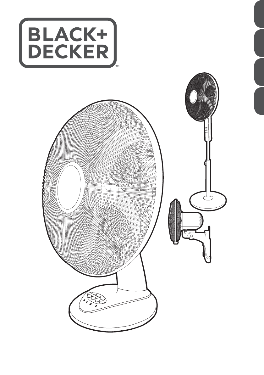
FD1620
Desk Fan
FW1620
Wall Fan
(Original instructions)
7 6 5 4 3 2 1
8
9
10
11
6 5 4 3 2 1
1112
10
8
9
2
7
Page 3
(Original instructions)
ENGLISH
FS1620
Pedestal fan
7 6
10
54321
9
11
FS1620R
Pedestal fan
54321
& Remote
6
8
8
9
7
16
10
12
14
15
13
16
11
13
14
12
15
3
Page 4

ENGLISH
(Original instructions)
Intended use
Your BLACK+DECKER FD1620 desk fan, FW1620 wall fan,
FS1620 Pedestal fan and FS1620R Pedestal fan with
remote control have been designed to create a flow of air.
This appliance is intended for indoor household use only.
This appliance is not intended to be used in:
• Staff kitchen areas in shops, offices and other working
environments;
• Farm houses;
• By clients in hotels, motels and other residential type
environments;
• Bed and breakfast type environments;
Thank you for choosing BLACK+DECKER. We hope that
you will enjoy using this product for many years.
Safety instructions
Warning! When using mains- powered appliances, basic
safety precautions, including the following, should always be
followed to reduce the risk of fire, electric shock and
personal injury.
• Read all of this manual carefully before using the
appliance.
• In order to avoid a hazard due to inadvertent resetting of
the thermal cut-out, this appliance must not be supplied
through an external switching device, such as a timer, or
connected to a circuit that is regularly switched on and
off by the utility.
• The intended use is described in this manual. The use of
any accessory or attachment or the performance of any
operation with this appliance other than those
recommended in this instruction manual may present a
risk of personal injury.
• Retain this manual for future reference.
Using your appliance
• Always take care when using the appliance.
• Do not use outdoors.
• Do not operate the appliance if your hands are wet. Do
not operate the appliance if you are barefoot.
• Guide the power supply cord neatly so it does not hang
over the edge of a worktop and cannot be caught
accidentally or tripped over.
• Never pull the power supply cord to disconnect the plug
from the socket. Keep the power supply cord away from
heat, oil and sharp edges.
• If the supply cord is damaged, it must be replaced by the
manufacturer, its service agent or similarly qualified
persons in order to avoid a hazard.
• Disconnect the appliance from the power supply when
not in use and before cleaning.
Warning! Long hair and loose clothing can be sucked into
the back of the fan.
Warning! Never allow the back of the fan to be covered with
curtains or other obstructions.
Safety of others
• This appliance is not intended for use by persons
(including children) with reduced physical, sensory or
mental capabilities, or lack of experience and knowledge,
unless they have been given supervision or instruction
concerning use of the appliance by a person responsible
for their safety.
• Children should be supervised to ensure that they do not
play with the appliance.
After use
• Switch off, remove the plug from the socket and let the
appliance cool down before leaving it unattended and
before changing, cleaning or inspecting any parts of the
appliance.
• When not in use, the appliance should be stored in a dry
place. Children should not have access to stored
appliances.
Inspection and repairs
• Switch off the appliance before cleaning, changing
accessories or approaching parts which move in use.
• Always allow the motor to stop turning before removing
any cover or accessory.
• Before use, check the appliance for damaged or
defective parts. Check for breakage of parts, damage to
switches and any other conditions that may affect its
operation.
• Do not use the appliance if any part is damaged or
defective.
• Have any damaged or defective parts repaired or
replaced by an authorised repair agent.
• Before use, check the power supply cord for signs of
damage, ageing and wear.
• Do not use the appliance if the power supply cord or
mains plug is damaged or defective.
• If the power supply cord or mains plug is damaged or
defective it must be repaired by an authorised repair
agent in order to avoid a hazard. Do not cut the power
supply cord and do not attempt to repair it yourself.
• Never attempt to remove or replace any parts other than
those specified in this manual.
• Do not attempt to repair the appliance. Take it to your
nearest BLACK+DECKER-owned or authorised Service
Centre for repair.
• Ensure that the fan is switched off and disconnected from
the mains supply before removing the guard.
4
Page 5

(Original instructions)
ENGLISH
Electrical safety
Before use, check that the mains voltage corresponds to the
voltage on the rating plate.
This appliance is double insulated in accordance
with EN 60335; therefore no earth wire is required.
• Appliance plugs must match the outlet. Never modify the
plug in any way.
• Do not use any adapter plugs with earthed (Class 1)
appliances. Unmodified plugs and matching outlets will
reduce the risk of electric shock.
• To avoid the risk of electric shock, do not immerse the
cord, plug or appliance in water or other liquid.
Mains plug replacement
If a new mains plug needs to be fitted:
• Safely dispose of the old plug.
• Connect the brown lead to the live terminal in the new
plug.
• Connect the blue lead to the neutral terminal.
• If the product is class I (earthed), connect the
green/yellow lead to the earth terminal
Note! If your product is class II double insulated (only 2
wires in the cord set), no connection is to be made to the
earth terminal. Follow the fitting instructions supplied with
good quality plugs.
Any replacement fuse must be of the same rating as the
original fuse supplied with the product.
Warning! The above section on mains plug replacement is
for authorized service centre persons.
FD1620 Desk Fan
Features
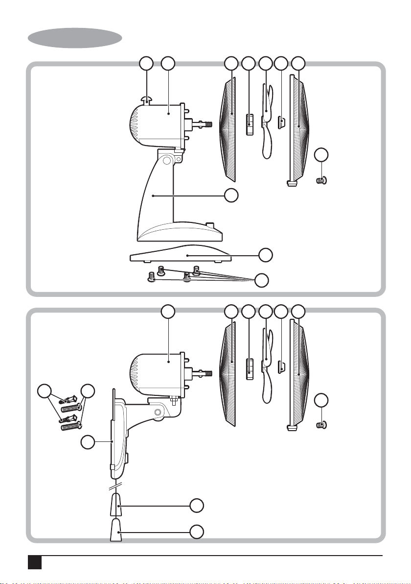
1. Front guard
2. Blade cap
3. Fan blade
4. Guard nut
5. Rear guard
6. Fan head
7. Oscillating knob
8. Guard screw
9. Fan unit
10. Base
11. Screw
Assembly
Note: Make sure your fan is switched off before connecting
to or disconnecting frompower supply.
Warning! Never use the fan without the guard in place or if
the guard is damaged.
Fitting the fan to the base
• Remove four screws(10) from the fan unit.
• Insert the fan unit into the base, re-fit the four screw into
the fan unit.
Fitting the fan blade and guard
• Remove the guard nut from the motor shaft by turning it
anti-clockwise.
• Place the rear guard by positioning it on the location pins
on the fan unit. Ensure that the rear guard is in the
correct orientation.
• Secure the guard on to the fan unit by re-fitting the guard
nut. Tighten the guard nut by turning it clockwise.
• Secure the fan blade on the motor shaft by fitting the
blade cap. Tighten the blade cap by turning it
anti-clockwise.
• Place the front guard onto the rear guard by positioning
the top clip on the uppermost part of the rear guard. Push
the top clip down and press the rim of the front guard
onto the rear guard ensuring a tight fit all the way round.
• Close the bottom clip. Tighten the bottom clip screw by
turning it clockwise.
Use
Warning! Never use the fan without the guard in place or if
the guard is damaged.
Switching on and off
• Your fan has three speed control to keep the desired air
flow through your room.
• 0 - Off
• 1 - Low
• 2 - Medium
• 3 - High
• To switch on, press the button to set the desired speed.
The fan will start.
• To switch off, press the “ 0 “ button.
Oscillation
• The fan can be set to oscillate by pushing Oscillating
Knob downwards.To stop the oscillating feature, pull up
the Oscillation Knob.
Adjusting the angle of the fan
The angle of the fan can be adjusted up and down.
• Tilt the head of the fan to the desired angle.
5
Page 6

ENGLISH
(Original instructions)
FW1620 Wall Fan
Features
1. Front guard
2. Blade cap
3. Fan blade
4. Guard nut
5. Rear Guard
6. Fan Unit
7. Guard Screw
8. Speed Pull Cord
9. Oscillation Pull Cord
10. Wall mount bracket
11. Wall screw
12. Wall plugs
Assembly
Note: Make sure your fan is switched off before connecting
to or disconnecting from power supply.
Warning! Never use the fan without the guard in place or if
the guard is damaged.
Wall mounting
When fixing to a wall,make sure that the fixing method is
suitable for the wall type and is appropriate to the weight of
the fan.
Warning! Before drilling into walls, check for the location of
wiring and pipes.
• Mark the location of the screw holes(within reach of an
electrical outlet).
• Secure the wall mount bracket using screws and wall
plugs.
• Hang the fan on the wall by placing the wall mount
bracket into the screw.
• The fan should installed so that the blades are more
than 2.3m above the floor.
Fitting the fan blade and guard
• Remove the guard nut from the motor shaft by turning it
anti-clockwise.
• Place the rear guard by positioning it on the location
pins on the fan unit. Ensure that the rear guard is in the
correct orientation.
• Secure the guard on to the fan unit by re-fitting the
guard nut. Tighten the guard nut by turning it clockwise.
• Secure the fan blade on the motor shaft by fitting the
blade cap. Tighten the blade cap by turning it
anti-clockwise.
• Place the front guard onto the rear guard by positioning
the top clip on the uppermost part of the rear guard.
Push the top clip down and press the rim of the front
guard onto the rear guard ensuring a tight fit all the way
round.
• Close the bottom clip. Tighten the bottom clip screw by
turning it clockwise.
Use
Warning! Never use the fan without the guard in place or if
the guard is damaged.
Switching on and off
• Your fan has three speed control to keep the desired air
flow through your room.
• 0 - Off
• 1 - Low
• 2 - Medium
• 3 - High
• To switch on, turn the knob to the desired speed. The fan
will start.
• To switch off, turn the knob to the “ 0 “ button.
• The speed can also be adjusted by pulling the right hand
cord. Each pull of the cord will advance the speed by one
setting until the fan returns to the off position.
Oscillation
The fan can oscillate when in use to circulate air around a
greater area.
• Pull the left hand cord to start oscillation.
• Pull the left hand cord again to stop oscillation.
Adjusting the angle of the fan
• The angle of the fan can be adjusted up and down.
• Hold the fan unit and tilt the head of the fan to the desired
angle.
FS1620 Pedestal Fan
Features
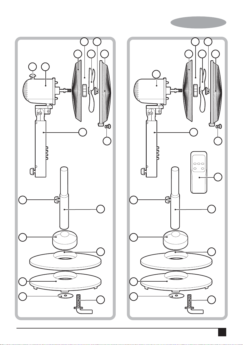
1. Front Guard
2. Blade Cap
3. Fan Blade
4. Guard Nut
5. Rear Guard
6. Fan Head
7. Oscillating Knob
8. Guard Screw
9. Fan unit
10. Set Screw
11. Support Tube
12. Base Cover
13. Round Base
14. Base
15. Washer
16. Screw
6
Page 7

(Original instructions)
ENGLISH
Assembly
Note: Make sure your fan is switched off before connecting
to or disconnecting frompower supply.
Warning! Never use the fan without the guard in place or if
the guard is damaged.
Assembling the base and stand
• Remove the washer (15) and screw (16) from the
support tube by turning it anti-clockwise.
• Place the support tube into the base. Re-insert the
screw into the support tube from underneath. Tighten
the screw by turning it clockwise.
Fitting the fan to the stand
• Remove the screw from the bottom of the fan unit by
turning it anti-clockwise.
• Place the fan unit onto the top of the support tube.
Re-insert the screw into the fan unit. Tighten the screw
by turning it clockwise.
Fitting the fan blade and guard
• Remove the guard nut from the motor shaft by turning it
anti-clockwise.
• Place the rear guard by positioning it on the location
pins on the fan unit. Ensure that the rear guard is in the
correct orientation.
• Secure the guard on to the fan unit by re-fitting the
guard nut. Tighten the guard nut by turning it clockwise.
• Secure the fan blade on the motor shaft by fitting the
blade cap. Tighten the blade cap by turning it
anti-clockwise.
• Place the front guard onto the rear guard by positioning
the top clip on the uppermost part of the rear guard.
Push the top clip down and press the rim of the front
guard onto the rear guard ensuring a tight fit all the way
round.
• Close the bottom clip. Tighten the bottom clip screw by
turning it clockwise.
Oscillation
• The fan can be set to oscillate by pushing Oscillating
Knob downwards.To stop the oscillating feature, pull up
the Oscillation Knob.
Adjusting the angle of the fan
The angle of the fan can be adjusted up and down.
• Tilt the head of the fan to the desired angle.
Adjusting the height of the fan
• Loosen the screw at the top of the support tube by
turning it anti-clockwise.
• Lift the fan to the desired height.
• Tighten the screw at the top of the support tube by
turning it clockwise.
FS1620R Pedestal Fan with remote Control
Features
1. Front Guard
2. Blade Cap
3. Fan Blade
4. Guard Nut
5. Rear Guard
6. Fan Head
7. Guard Screw
8. Fan unit
9. Set Screw
10. Support Tube
11. Base Cover
12. Round Base
13. Base
14. Washer
15. Screw
16. Remote Control
Use
Warning! Never use the fan without the guard in place or if
the guard is damaged.
Switching on and off
• Your fan has three speed control to keep the desired air
flow through your room.
• 0 - Off
• 1 - Low
• 2 - Medium
• 3 - High
• To switch on, press the button to set the desired speed.
The fan will start.
• To switch off, press the “ 0 “ button.
Assembly
Note: Make sure your fan is switched off before connecting to
or disconnecting frompower supply.
Warning! Never use the fan without the guard in place or if
the guard is damaged.
Assembling the base and stand
• Remove the flat washer (14) and screw (15) from the
support tube by turning it anti-clockwise.
• Place the support tube into the base. Re-insert the screw
into the support tube from underneath. Tighten the screw
by turning it clockwise.
Fitting the fan to the stand
• Remove the screw from the bottom of the fan unit by
turning it anti-clockwise.
7
Page 8
ENGLISH
(Original instructions)
• Place the fan unit onto the top of the support tube.
Re-insert the screw into the fan unit. Tighten the screw
by turning it clockwise.
Fitting the fan blade and guard
• Remove the guard nut from the motor shaft by turning it
anti-clockwise.
• Place the rear guard by positioning it on the location
pins on the fan unit. Ensure that the rear guard is in the
correct orientation.
• Secure the guard on to the fan unit by fitting the guard
nut. Tighten the guard nut by turning it clockwise.
• Secure the fan blade on the motor shaft by fitting the
blade cap. Tighten the blade cap by turning it
anti-clockwise.
• Place the front guard onto the rear guard by positioning
the top clip on the uppermost part of the rear guard.
Push the top clip down and press the rim of the front
guard onto the rear guard ensuring a tight fit all the way
round.
• Close the bottom clip. Tighten the bottom clip screw by
turning it clockwise.
Use
Warning! Never use the fan without the guard in place or if
the guard is damaged.
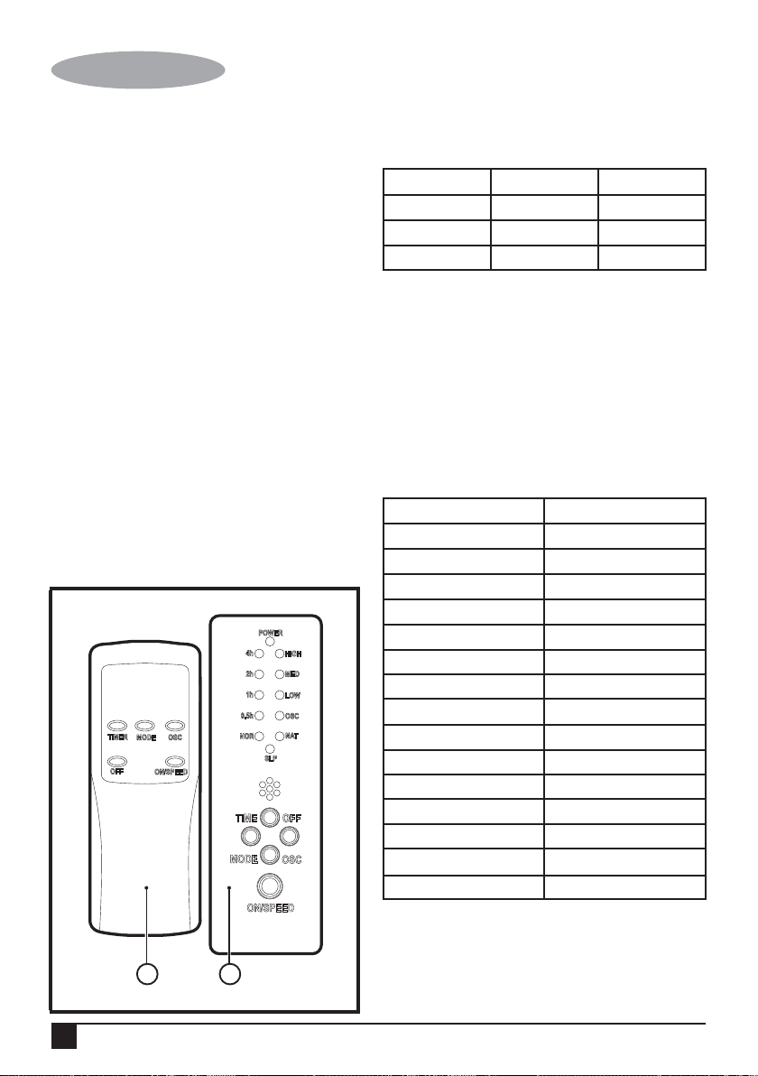
Note: All controls can be operated from the fan unit or from
the remote control.
POWER
4h
HIGH
2h
MED
1h
LOW
0.5h
OSC
NAT
TIMER
MODE OSC
OFF
ON/SPEED
16 8
NOR
MODE
SLP
OFFTIME
OSC
ON/SPEED
Switching on and off
Your fan has three speed control to keep the desired air flow
through your room.
Symbol Speed Press Button
LOW Low 1 Time
MED Medium 2 Times
HIGH High 3 Times
• To switch on, press the “ON/SPEED” button the required
number of times to set the desired speed. The fan will
start.
• To switch off, press the “OFF” button.
Oscillation
The fan can oscillate when in use to circulate air around a
greater area.
• Press the “OSC” button to start oscillation.
Timer
The timer can be used to set the running time of the fan.
Symbol Press Button
0.5 Hour 1 Time
1 Hour 2 Times
1.5 Hours 3 Times
2 Hours 4 Times
2.5 Hours 5 Times
3 Hours 6 Times
3.5 Hours 7 Times
4 Hours 8 Times
4.5 Hours 9 Times
5 Hours 10 Times
5.5 Hours 11 Times
6 Hours 12 Times
6.5 Hours 13 Times
7 Hours 14 Times
7.5 Hours 15 Times
Press the TIME button the required number of times to set
the run time. The fan will automatically stop when the run
time is reached.
8
Page 9
(Original instructions)
ENGLISH
Mode
Mode Press Button
NOR = Normal Press ON/SPEED button 1 time
NAT = Natural Press MODE button 1 time
SLP = Sleep Press MODE button 2 times
NOR = Normal Press MODE button 3 times
• When the the ON/SPEED button is pressed, the NOR
mode indicator lights up red.
• Press the MODE button the required number of times to
set the MODE.
• NOR Mode (the NOR mode indicator lights up red.):You
can adjust the speed settings yourself at any time.
• NAT Mode (the NAT mode indicator lights up red.)
• If the HIGH speed is selected, the speed switches
between high-medium-slow-off.
• If you have selected MED speed, the speed switches
between medium-slow-off.
• In the LOW mode the speed switches between slow-off.
• SLP Mode( the SLP mode indicator lights up red.)
• If the HIGH speed is selected: the fan operates as in
“NAT mode” for first 30 minutes on the HIGH speed
setting. It then opreates for 30 minutes as in “NAT mode”
on the MED speed setting. For the remaining time, the
fan works as in “NAT mode” on the LOW speed setting.
• On the MED speed setting:the fan works as in “NAT
mode” for the first 30 minutes on the MED speed setting.
For the remaining time, the fan works as in “NAT mode”
on the LOW speed setting.
• If the LOW speed setting is selected: Switch between
slow speed and shutdown of the fan as in “NAT mode”.
Adjusting the angle of the fan
The angle of the fan can be adjusted up and down.
• Tilt the head of the fan to the desired angle.
Adjusting the height of the fan
• Loosen the screw at the top of the support tube by
turning it anti-clockwise.
• Lift the fan to the desired height.
• Tighten the screw at the top of the support tube by
turning it clockwise.
Cleaning and maintenance
Warning! Before cleaning and maintenance, switch the
appliance off and remove the plug from the socket.
Warning! Allow the unit to thoroughly cool down before
attempting to clean it.
• Do not immerse the appliance into liquid.
• Never use dilutent or benzene, chemical wiping cloths,
plastic brush or metal brush.
• The basketand pan can be washed in hot soapy water.
Rinse & dry thoroughly after cleaning.
• Use a damp cloth to wipe the outside of the body (1) and
the internal cavity.
• Keep the power cord, control panel clean and dry,
otherwise it may cause problems.
Caution: NEVER immerse the appliance in water or any
liquids. Make sure the appliance is thoroughly dried before
use.
Protecting the environment
Separate collection. This product must not be
disposed of with normal household waste.
Should you find one day that your Black+Decker product
needs replacement, or if it is of no further use to you, do not
dispose of it with other household waste. Make this product
available for separate collection.
• Black+Decker provides a facility for recycling
Black+Decker products once they have reached the end
of their working life. This service is provided free of
charge. To take advantage of this service please return
your product to any authorised repair agent who will
collect them on our behalf.
• You can check the location of your nearest authorised
repair agent by contacting your local Black+Decker
office at the address indicated in this manual.
Alternatively, a list of authorized Black+Decker repair
agents and full details of our after-sales service and
contact are available on the Internet at:
www.2helpU.com.
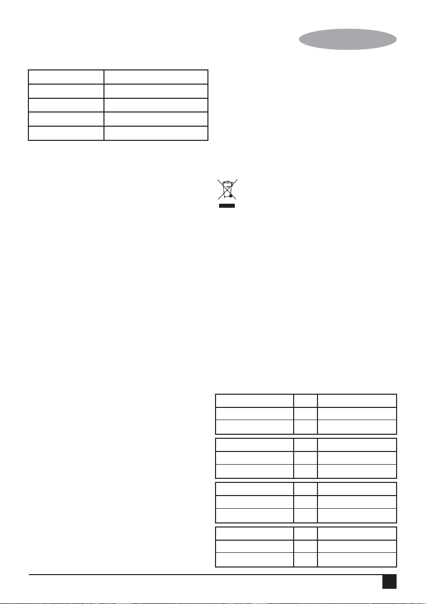
Technical data
FD1620
Input voltage VAC 220 - 240
Power input W 60
FW1620
Input voltage VAC 220 - 240
Power input W 55
FS1620
Input voltage VAC 220 - 240
Power input W 60
FS1620R
Input voltage VAC 220 - 240
Power input W 60
9
Page 10
ENGLISH
(Original instructions)
Warranty
Black+Decker is confident of the quality of its products and
offers an outstanding warranty.
This warranty statement is in addition to and in no way
prejudices your statutory rights.
If a Black+Decker product becomes defective due to faulty
materials, workmanship or lack of conformity, within 24
months from the date of purchase, Black+Decker warranty
to replace defective parts, repair products subjected to fair
wear and tear or replace such products to ensure minimum
inconvenience to the customer unless:
The product has been used for trade, professional or
hire purposes;
The product has been subjected to misuse or neglect;
The product has sustained damage through foreign
objects, substances or accidents;
Repairs have been attempted by persons other than
authorised repair agents or Black+Decker service staff.
To claim on the warranty, you will need to submit proof of
purchase to the seller or an authorised repair agent. You can
check the location of your nearest authorised repair agent by
contacting your local Black+Decker office at the address
indicated in this manual.
Alternatively, a list of authorised Black+Decker repair
agents and full details of our after-sales service and contacts
are available on the Internet at: www.2helpU.com.
10
Page 11

(Traduction des instructions d'origine)
FRANÇAIS
Usage prévu
Vos ventilateur de bureau BLACK+DECKER FD1620,
ventilateur mural FW1620, ventilateur sur pied FS1620 et
ventilateur sur pied télécommandé FS1620R ont été conçus
pour générer une ventilation.
Cet appareil est destiné à une utilisation domestique interne
uniquement.
Cet appareil n'est pas destiné à une utilisation :
• dans les cuisines pour les employés de boutiques, de
bureaux et d’autres environnements profesionnels ;
• dans les fermes ;
• par les clients d’hôtels, de motels et autres
environnements de type résidentiels ;
• dans les environnements de type maison d’hôte.
Merci d’avoir choisi BLACK+DECKER. Nous espérons que
vous profiterez de ce produit pendant de nombreuses
années.
Consignes de sécurité
Avertissement ! L’utilisation d’appareils électriques requiert
le respect de consignes de sécurité de base, notamment
celles indiquées ci-après, afin de réduire les risques
d’incendie, d’électrocution et de blessure.
• Lisez attentivement ce manuel dans son intégralité
avant d’utiliser l’appareil.
• Pour éviter tout danger résultant de la réinitialisation par
inadvertance du coupe-circuit thermique, évitez
d’alimenter cet appareil au moyen d’un dispositif de
commutation externe tel qu’une minuterie, ou de le
connecter à un circuit régulièrement mis sous/hors
tension par le réseau public.
• L’usage prévu est décrit dans le présent manuel.
L’utilisation d’un accessoire ou d'une pièce jointe ou
l’exécution de toute opération avec cet appareil autre
que ceux qui sont recommandés dans ce mode d’emploi
peut présenter un risque de blessure.
• Conservez ce manuel à titre de référence.
Utilisation de l’appareil
• Utilisez toujours l’appareil avec précaution.
• Ne l’utilisez pas à l’extérieur.
• N’utilisez pas l’appareil avec les mains mouillées.
N’utilisez pas l’appareil pieds nus.
• Positionnez correctement le cordon d’alimentation de
sorte qu’il ne pende pas du bord d’un plan de travail et
d’éviter tout accrochage et trébuchement accidentels.
• Ne tirez jamais sur le cordon d’alimentation pour
débrancher la fiche du secteur. Maintenez le cordon
d’alimentation à l’écart des sources de chaleur, de l’huile
et des bords tranchants.
• Si le cordon d’alimentation est abîmé, il doit être
remplacé par le fabricant, un agent de service agréé ou
d’autres personnes tout autant qualifiées afin d’éviter
tout danger.
• Débranchez l’appareil de l’alimentation électrique en cas
de non-utilisation et avant de le nettoyer.
Avertissement ! Les cheveux longs et les vêtements amples
peuvent être aspirés à l'arrière du ventilateur.
Avertissement ! Évitez toujours que l'arrière du ventilateur
soit recouvert par des rideaux ou d'autres objets.
Sécurité d’autrui
• Cet appareil n’est pas prévu pour être utilisé par des
personnes (y compris les enfants) présentant des
capacités physiques, sensorielles ou mentales réduites,
ou manquant d’expérience et de connaissances, sans
surveillance ou sans avoir reçu d’instructions concernant
l’utilisation de l’appareil de la part d’une personne
responsable de leur sécurité.
• Les enfants doivent être surveillés pour s’assurer qu’ils
ne jouent pas avec l’appareil.
Après utilisation
• Éteignez et débranchez la fiche du secteur et laissez
l’appareil refroidir avant de le laisser sans surveillance et
avant d’en remplacer, nettoyer ou inspecter les pièces.
• Lorsqu’il n’est pas utilisé, l’appareil doit être rangé à un
endroit sec. L’appareil doit être rangé hors de portée des
enfants.
Inspection et réparations
• Mettez l’appareil hors tension avant de le nettoyer, de
remplacer des accessoires ou d’approcher des pièces
mobiles en cours d’utilisation.
• Veillez toujours à attendre l’arrêt total du moteur avant de
retirer un accessoire ou un couvercle.
• Avant d’utiliser l’appareil, vérifiez qu’aucune pièce n’est
endommagée ou défectueuse. Vérifiez si des pièces ne
sont pas cassées, si les interrupteurs ne sont pas
endommagés, et toutes les autres conditions qui peuvent
affecter son fonctionnement.
• N’utilisez pas l’appareil si une pièce est endommagée ou
défectueuse.
• Faites réparer ou remplacer les pièces endommagées ou
défectueuses par un agent de service agréé.
• Avant l'utilisation, vérifiez que le cordon d'alimentation ne
présente pas de signes de dommages, de vieillissement
et d'usure.
• N’utilisez pas l’appareil si la fiche ou le cordon
d’alimentation est endommagé ou défectueux.
• Si la fiche ou le cordon d’alimentation est endommagé ou
défectueux, sa réparation doit être effectuée par un agent
de réparation agréé afin d’éviter tout danger. Ne coupez
pas le cordon d’alimentation et n’essayez pas de le
réparer par vos propres moyens.
• N’essayez jamais de retirer ou de remplacer des pièces
différentes de celles qui sont indiquées dans le présent
manuel.
11
Page 12

FRANÇAIS
(Traduction des instructions d'origine)
• N'essayez pas de réparer l'appareil vous-même.
Faites-le réparer par votre Centre de services
BLACK+DECKER ou un fournisseur autorisé.
• Assurez-vous que le ventilateur est éteint et débranché
de l'alimentation secteur avant de retirer la protection.
Sécurité électrique
Avant d’utiliser l’appareil, vérifiez que la tension secteur
correspond à celle de la plaque signalétique.
Cet appareil dispose d’une double isolation
conformément à la norme EN 60335 ; par
conséquent, l’utilisation du fil de terre n’est pas
requise.
• La fiche de l’appareil doit correspondre à la prise
secteur. Ne modifiez jamais la fiche, de quelque manière
que ce soit.
• N'utilisez pas de fiches d'adaptation avec les appareils
reliés à la terre (classe 1). L’utilisation de fiches non
modifiées et de prises murales correspondantes réduira
le risque d’électrocution.
• Pour éviter le risque d’électrocution, ne plongez pas le
cordon, la fiche ou l’appareil dans de l’eau ou tout autre
liquide.
Changement de la fiche
En cas de besoin de montage d’une nouvelle fiche :
• Mettez dûment l’ancienne fiche au rebut.
• Connectez le fil marron à la borne sous tension de la
nouvelle fiche.
• Connectez le fil bleu à la borne neutre.
• Si le produit est de classe I (relié à la terre), connectez
le fil vert/jaune à la bonne de terre.
Remarque ! Si vous disposez d’un produit à double isolation
de classe II (2 fils uniquement dans le cordon), aucun
raccordement à la borne de terre n’est nécessaire. Suivez
les consignes d’installation fournies avec les fiches de
bonne qualité.
Tout fusible de rechange doit avoir les mêmes caractéristiques nominales que le fusible d’origine fourni avec le
produit.
Avertissement ! La section ci-dessus concernant le
remplacement de la fiche électrique s’adresse au personnel
des centres de service agréés.
Ventilateur de bureau FD1620 Composition
1. Protection avant
2. Capuchon de lame
3. Lame de ventilateur
4. Écrou de protection
5. Protection arrière
6. Tête de ventilateur
7. Bouton d'oscillation
8. Vis de protection
9. Unité de ventilateur
10. Base
11. Vis
Montage
Remarque : Assurez-vous que votre ventilateur est éteint
avant de le brancher ou de le débrancher de l'alimentation.
Avertissement ! N'utilisez jamais le ventilateur si la
protection n'est pas en place ou si elle est abîmée.
Installation du ventilateur sur la base
• Retirez quatre vis (10) de l'unité de ventilateur.
• Introduisez le ventilateur dans la base, replacez les vis
dans l'unité de ventilateur.
Installation de la lame de ventilateur et de la
protection
• Retirez l'écrou de protection de l'arbre du moteur en le
tournant dans le sens inverse des aiguilles d'une montre.
• Placez la protection arrière en la mettant sur les ergots
de positionnement de l'unité de ventilateur. Assurez-vous
que la protection arrière se trouve dans le bon sens.
• Fixez la protection sur l'unité de ventilateur en replaçant
l'écrou de protection. Serrez l'écrou en le tournant dans
le sens des aiguilles d'une montre.
• Fixez la lame de ventilateur sur l'arbre du moteur en
installant le capuchon de lame. Serrez le capuchon de
lame en le tournant dans le sens inverse des aiguilles
d'une montre.
• Placez la protection avant sur la protection arrière en
positionnant le clip supérieur sur la partie la plus haute
de la protection arrière. Appuyez sur le clip supérieur et
poussez le bord de la protection avant sur la protection
arrière pour assurer un montage serré tout autour.
• Refermez le clip inférieur. Serrez la vis de clip inférieur
en la tournant dans le sens des aiguilles d'une montre.
Mode d’emploi
Avertissement ! N'utilisez jamais le ventilateur si la
protection n'est pas en place ou si elle est abîmée.
Mise sous et hors tension
• Votre ventilateur dispose d'une commande à trois
vitesses pour conserver la ventilation désirée dans la
pièce.
• 0 - Arrêt
• 1 - Faible
• 2 - Moyenne
• 3 - Haute
• Pour mettre sous tension, appuyez sur le bouton pour
régler la vitesse souhaitée. Le ventilateur se met en
marche.
• Pour mettre hors tension, appuyez sur le bouton « 0 ».
12
Page 13

(Traduction des instructions d'origine)
FRANÇAIS
Oscillation
• Il est possible de faire osciller le ventilateur en appuyant
sur le bouton d'oscillation. Pour arrêter l'oscillation, tirez
le bouton d'oscillation vers le haut.
Réglage de l'angle du ventilateur
L'angle du ventilateur peut être réglé vers le haut et vers le
bas.
• Inclinez la tête du ventilateur à l'angle souhaité.
Ventilateur mural FW1620 Composition
1. Protection avant
2. Capuchon de lame
3. Lame de ventilateur
4. Écrou de protection
5. Protection arrière
6. Unité de ventilateur
7. Vis de protection
8. Cordon de vitesse
9. Cordon d'oscillation
10. Support de fixation murale
11. Vis murale
12. Fiches murales
Montage
Remarque : Assurez-vous que votre ventilateur est éteint
avant de le brancher ou de le débrancher de l'alimentation.
Avertissement ! N'utilisez jamais le ventilateur si la
protection n'est pas en place ou si elle est abîmée.
Fixation murale
Lors de la fixation murale, assurez-vous que la méthode est
adaptée au type de mur et au poids du ventilateur.
Avertissement ! Avant de percer le mur, vérifiez
l'emplacement des câbles et tuyaux.
• Tracez un repère à l'emplacement des orifices pour vis
(à proximité d'une prise électrique).
• Fixez le support mural à l'aide des vis et des fiches
murales.
• Accrochez le ventilateur au mur en plaçant le support
dans la vis.
• Le ventilateur doit être posé de sorte que les lames
soient situées à plus de 2,3 m au-dessus du sol.
Installation de la lame de ventilateur et de la
protection
• Retirez l'écrou de protection de l'arbre du moteur en le
tournant dans le sens inverse des aiguilles d'une
montre.
• Placez la protection arrière en la mettant sur les ergots
de positionnement de l'unité de ventilateur. Assurez-vous
que la protection arrière se trouve dans le bon sens.
• Fixez la protection sur l'unité de ventilateur en replaçant
l'écrou de protection. Serrez l'écrou en le tournant dans
le sens des aiguilles d'une montre.
• Fixez la lame de ventilateur sur l'arbre du moteur en
installant le capuchon de lame. Serrez le capuchon de
lame en le tournant dans le sens inverse des aiguilles
d’une montre.
• Placez la protection avant sur la protection arrière en
positionnant le clip supérieur sur la partie la plus haute
de la protection arrière. Appuyez sur le clip supérieur et
poussez le bord de la protection avant sur la protection
arrière pour assurer un montage serré tout autour.
• Refermez le clip inférieur. Serrez la vis de clip inférieur
en la tournant dans le sens des aiguilles d'une montre.
Mode d’emploi
Avertissement ! N'utilisez jamais le ventilateur si la
protection n'est pas en place ou si elle est abîmée.
Mise sous et hors tension
• Votre ventilateur dispose d'une commande à trois
vitesses pour conserver la ventilation désirée dans la
pièce.
• 0 - Arrêt
• 1 - Faible
• 2 - Moyenne
• 3 - Haute
• Pour mettre sous tension, placez le bouton sur la vitesse
souhaitée. Le ventilateur se met en marche.
• Pour mettre hors tension, placez le bouton sur « 0 ».
• La vitesse peut aussi être réglée en tirant sur le cordon
droit. Chaque fois que le cordon est tiré, la vitesse
avance d'un niveau jusqu'à atteindre la position d'arrêt.
Oscillation
Lorsqu'il est utilisé, le ventilateur peut osciller pour ventiler
une zone plus vaste.
• Tirez le cordon gauche pour démarrer l'oscillation.
• Tirez à nouveau le cordon gauche pour arrêter
l'oscillation.
Réglage de l'angle du ventilateur
• L'angle du ventilateur peut être réglé vers le haut et vers
le bas.
• Maintenez l'unité de ventilateur et inclinez la tête du
ventilateur à l'angle souhaité.
Ventilateur sur pied FS1620 Composition
1. Protection avant
2. Capuchon de lame
13
Page 14

FRANÇAIS
(Traduction des instructions d'origine)
3. Lame de ventilateur
4. Écrou de protection
5. Protection arrière
6. Tête de ventilateur
7. Bouton d'oscillation
8. Vis de protection
9. Unité de ventilateur
10. Vis de fixation
11. Tube de support
12. Couvercle de base
13. Base circulaire
14. Base
15. Rondelle
16. Vis
Montage
Remarque : Assurez-vous que votre ventilateur est éteint
avant de le brancher ou de le débrancher de l'alimentation.
Avertissement ! N'utilisez jamais le ventilateur si la
protection n'est pas en place ou si elle est abîmée.
Montage de la base et du socle
• Retirez la rondelle (15) et la vis (16) du tube de support
en la tournant dans le sens inverse des aiguilles d'une
montre.
• Placez le tube de support dans la base. Réintroduisez la
vis dans le tube de support par en dessous. Serrez la
vis en la tournant dans le sens des aiguilles d'une
montre.
Installation du ventilateur sur le socle
• Retirez la vis de la partie inférieure de l'unité de
ventilateur en la tournant dans le sens inverse des
aiguilles d'une montre.
• Placez l'unité de ventilateur sur la partie supérieure du
tube de support. Réintroduisez la vis dans l'unité de
ventilateur. Serrez la vis en la tournant dans le sens des
aiguilles d'une montre.
Installation de la lame de ventilateur et de la
protection
• Retirez l'écrou de protection de l'arbre du moteur en le
tournant dans le sens inverse des aiguilles d'une
montre.
• Placez la protection arrière en la mettant sur les ergots
de positionnement de l'unité de ventilateur.
Assurez-vous que la protection arrière se trouve dans le
bon sens.
• Fixez la protection sur l'unité de ventilateur en replaçant
l'écrou de protection. Serrez l'écrou en le tournant dans
le sens des aiguilles d'une montre.
• Fixez la lame de ventilateur sur l'arbre du moteur en
installant le capuchon de lame. Serrez le capuchon de
lame en le tournant dans le sens inverse des aiguilles
d’une montre.
• Placez la protection avant sur la protection arrière en
positionnant le clip supérieur sur la partie la plus haute
de la protection arrière. Appuyez sur le clip supérieur et
poussez le bord de la protection avant sur la protection
arrière pour assurer un montage serré tout autour.
• Refermez le clip inférieur. Serrez la vis de clip inférieur
en la tournant dans le sens des aiguilles d'une montre.
Mode d’emploi
Avertissement ! N'utilisez jamais le ventilateur si la
protection n'est pas en place ou si elle est abîmée.
Mise sous et hors tension
• Votre ventilateur dispose d'une commande à trois
vitesses pour conserver la ventilation désirée dans la
pièce.
• 0 - Arrêt
• 1 - Faible
• 2 - Moyenne
• 3 - Haute
• Pour mettre sous tension, appuyez sur le bouton pour
régler la vitesse souhaitée. Le ventilateur se met en
marche.
• Pour mettre hors tension, appuyez sur le bouton « 0 ».
Oscillation
• Il est possible de faire osciller le ventilateur en appuyant
sur le bouton d'oscillation. Pour arrêter l'oscillation, tirez
le bouton d'oscillation vers le haut.
Réglage de l'angle du ventilateur
L'angle du ventilateur peut être réglé vers le haut et vers le
bas.
• Inclinez la tête du ventilateur à l'angle souhaité.
Réglage de la hauteur du ventilateur
• Desserrez la vis sur la partie supérieure du tube de
support en la tournant dans le sens inverse des aiguilles
d'une montre.
• Levez le ventilateur à la hauteur souhaitée.
• Serrez la vis sur la partie supérieure du tube de support
en la tournant dans le sens des aiguilles d'une montre.
Ventilateur sur pied avec télécommande
FS1620R Composition
1. Protection avant
2. Capuchon de lame
14
Page 15

(Traduction des instructions d'origine)
FRANÇAIS
3. Lame de ventilateur
4. Écrou de protection
5. Protection arrière
6. Tête de ventilateur
7. Vis de protection
8. Unité de ventilateur
9. Vis de fixation
10. Tube de support
11. Couvercle de base
12. Base circulaire
13. Base
14. Rondelle
15. Vis
16. Télécommande
Montage
Remarque : Assurez-vous que votre ventilateur est éteint
avant de le brancher ou de le débrancher de l'alimentation.
Avertissement ! N'utilisez jamais le ventilateur si la
protection n'est pas en place ou si elle est abîmée.
Montage de la base et du socle
• Retirez la rondelle plate (14) et la vis (15) du tube de
support en la tournant dans le sens inverse des aiguilles
d'une montre.
• Placez le tube de support dans la base. Réintroduisez la
vis dans le tube de support par en dessous. Serrez la
vis en la tournant dans le sens des aiguilles d'une
montre.
Installation du ventilateur sur le socle
• Retirez la vis de la partie inférieure de l'unité de
ventilateur en la tournant dans le sens inverse des
aiguilles d'une montre.
• Placez l'unité de ventilateur sur la partie supérieure du
tube de support. Réintroduisez la vis dans l'unité de
ventilateur. Serrez la vis en la tournant dans le sens des
aiguilles d'une montre.
Installation de la lame de ventilateur et de la
protection
• Retirez l'écrou de protection de l'arbre du moteur en le
tournant dans le sens inverse des aiguilles d'une
montre.
• Placez la protection arrière en la mettant sur les ergots
de positionnement de l'unité de ventilateur.
Assurez-vous que la protection arrière se trouve dans le
bon sens.
• Fixez la protection sur l'unité de ventilateur en replaçant
l'écrou de protection. Serrez l'écrou en le tournant dans
le sens des aiguilles d'une montre.
• Fixez la lame de ventilateur sur l'arbre du moteur en
installant le capuchon de lame. Serrez le capuchon de
lame en le tournant dans le sens inverse des aiguilles
d'une montre.
• Placez la protection avant sur la protection arrière en
positionnant le clip supérieur sur la partie la plus haute
de la protection arrière. Appuyez sur le clip supérieur et
poussez le bord de la protection avant sur la protection
arrière pour assurer un montage serré tout autour.
• Refermez le clip inférieur. Serrez la vis de clip inférieur
en la tournant dans le sens des aiguilles d'une montre.
Mode d’emploi
Avertissement ! N'utilisez jamais le ventilateur si la
protection n'est pas en place ou si elle est abîmée.
Remarque : Toutes les commandes peuvent être actionnées
à partir du ventilateur ou de la télécommande.
POWER
4h
HIGH
2h
MED
1h
LOW
0.5h
OSC
NAT
TIMER
OFF
MODE OSC
ON/SPEED
NOR
MODE
ON/SPEED
SLP
OFFTIME
OSC
16 8
Mise sous et hors tension
Votre ventilateur dispose d'une commande à trois vitesses
pour conserver la ventilation désirée dans la pièce.
Symbole Vitesse Pression sur le
LOW Faible 1 fois
MED Moyenne 2 fois
HIGH Haute 3 fois
15
Page 16

FRANÇAIS
(Traduction des instructions d'origine)
• Pour mettre sous tension, appuyez sur le bouton «
ON/SPEED » le nombre de fois nécessaire pour régler
la vitesse souhaitée. Le ventilateur se met en marche.
• Pour mettre hors tension, appuyez sur le bouton «OFF».
Oscillation
Lorsqu'il est utilisé, le ventilateur peut osciller pour ventiler
une zone plus vaste.
• Appuyez sur le bouton « OSC » pour démarrer
l'oscillation.
Temporisateur
Le temporisateur peut être utilisé pour régler la durée de
fonctionnement du ventilateur.
Symbole Pression sur le bouton
0.5 heure 1 fois
1 heure 2 fois
1.5 heure 3 fois
2 heure 4 fois
2.5 heure 5 fois
3 heure 6 fois
3.5 heure 7 fois
4 heure 8 fois
4.5 heure 9 fois
5 heure 10 fois
5.5 heure 11 fois
6 heure 12 fois
6.5 heure 13 fois
7 heure 14 fois
7.5 heure 15 fois
Appuyez sur le bouton TIME le nombre de fois nécessaire
pour régler la durée de fonctionnement. Le ventilateur
s'arrête automatiquement une fois la durée de
fonctionnement écoulée.
Mode
Mode Pression sur le bouton
NOR = Normal
NAT = Naturel
SLP = Veille
NOR = Normal Appuyez sur le bouton MODE 3
• Lorsque le bouton ON/SPEED est enfoncé, le témoin du
mode NOR s'allume en rouge.
16
Appuyez sur le bouton ON/SPEED 1 fois
Appuyez sur le bouton MODE 1 fois
Appuyez sur le bouton MODE 2 fois
• Appuyez sur le bouton MODE le nombre de fois
nécessaire pour régler le MODE.
• Mode NOR (le témoin du mode NOR s'allume en rouge) :
vous pouvez vous-même régler la vitesse à tout moment.
• Mode NAT (le témoin du mode NAT s'allume en rouge).
• Si le niveau de vitesse HIGH est sélectionné, la vitesse
bascule de la manière suivante :
haute-moyenne-faible-arrêt.
• Si vous sélectionnez le niveau de vitesse MED, la vitesse
bascule de la manière suivante : moyenne-faible-arrêt.
• En mode LOW, la vitesse bascule de faible à arrêt.
• Mode SLP (le témoin du mode SLP s'allume en rouge).
• Si le niveau de vitesse HIGH est sélectionné : le
ventilateur fonctionne comme en « mode NAT » pendant
les 30 première minutes au niveau de vitesse HIGH. Il
fonctionne ensuite pendant 30 minutes comme en «
mode NAT » au niveau de vitesse MED. Le reste du
temps, le ventilateur fonctionne comme en « mode NAT »
au niveau de vitesse LOW.
• Au niveau de vitesse MED : le ventilateur fonctionne
comme en « mode NAT » pendant les 30 première
minutes au niveau de vitesse MED. Le reste du temps, le
ventilateur fonctionne comme en « mode NAT » au
niveau de vitesse LOW.
• Si le niveau de vitesse LOW est sélectionné :
basculement du niveau de vitesse faible à l'arrêt du
ventilateur comme en « mode NAT ».
Réglage de l'angle du ventilateur
L'angle du ventilateur peut être réglé vers le haut et vers le
bas.
• Inclinez la tête du ventilateur à l'angle souhaité.
Réglage de la hauteur du ventilateur
• Desserrez la vis sur la partie supérieure du tube de
support en la tournant dans le sens inverse des aiguilles
d'une montre.
• Levez le ventilateur à la hauteur souhaitée.
• Serrez la vis sur la partie supérieure du tube de support
en la tournant dans le sens des aiguilles d'une montre.
Nettoyage et entretien
Avertissement ! Avant le nettoyage et l’entretien, éteignez
l’appareil et débranchez la fiche du secteur.
Avertissement ! Laissez l’appareil refroidir complètement
avant de commencer le nettoyage.
• Ne plongez pas l’appareil dans un liquide.
• N’utilisez pas de diluant ou de benzène, ni de lingettes
pré-imbibées de produits chimiques, ni de brosses en
plastique ou en métal.
• Le panier et la casserole peuvent être lavés à l’eau
chaude savonneuse. Rincez et séchez soigneusement
après le nettoyage.
Page 17

(Traduction des instructions d'origine)
FRANÇAIS
• Utilisez un chiffon humide pour nettoyer la partie
extérieure du corps (1) et la cavité interne.
• Gardez le cordon d’alimentation et le panneau de
commande propres et secs pour éviter tout problème.
Attention : Ne plongez JAMAIS l’appareil dans de l’eau ou
dans tout autre liquide. Assurez-vous que l’appareil est
totalement sec avant de l’utiliser.
Protection de l'environnement
Collecte séparée. Ce produit ne doit pas être jeté
avec les déchets domestiques normaux.
Si vous décidez de remplacer ce produit BLACK+DECKER,
ou si vous n'en avez plus l'utilité, ne le jetez pas avec vos
déchets domestiques Rendez-le disponible pour une
collecte séparée.
• BLACK+DECKER fournit un dispositif permettant de
collecter et de recycler les produits BLACK+DECKER
lorsqu'ils ont atteint la fin de leur cycle de vie. Pour
pouvoir profiter de ce service, veuillez retourner votre
produit à un réparateur agréé qui se chargera de le
collecter pour nous.
• Pour connaître l'adresse du réparateur agréé le plus
proche de chez vous, contactez le bureau
BLACK+DECKER à l'adresse indiquée dans ce manuel.
Vous pourrez aussi trouvez un liste des réparateurs
agréés de BLACK+DECKER et de plus amples détails
sur notre service après-vente sur le site Internet à
l'adresse suivante : www.2helpU.com
Caractéristiques techniques
FD1620
Tension d’entrée VAC 220 - 240
Alimentation électrique W 60
Garantie
BLACK+DECKER est confiant dans la qualité de ses produits
et vous offre une garantie très étendue.
Ce certificat de garantie est un document supplémentaire et
ne peut en aucun cas se substituer à vos droits légaux.
Si un produit BLACK+DECKER s'avère défectueux en raison
de matériaux en mauvaises conditions, d'une erreur
humaine, ou d'un manque de conformité dans les 24 mois
suivant la date d'achat, BLACK+DECKER garantit le
remplacement des pièces défectueuses, la réparation des
produits usés ou cassés ou remplace ces produits à la
convenance du client, sauf dans les circonstances suivantes:
Le produit a été utilisé dans un but commercial,
professionnel, ou a été loué.
Le produit a été mal utilisé ou avec négligence.
Le produit a subi des dommages à cause d'objets
étrangers, de substances ou à cause d'accidents.
Des réparations ont été tentées par des techniciens ne
faisant pas partie du service technique de
BLACK+DECKER
Pour avoir recours à la garantie, il est nécessaire de fournir
une preuve d'achat au vendeur ou à un réparateur agréé.
Pour connaître l'adresse du réparateur agréé le plus proche
de chez vous, contactez le bureau BLACK+DECKER à
l'adresse indiquée dans ce manuel.
Vous pourrez aussi trouver une liste des réparateurs agréés
de BLACK+DECKER et de plus amples détails sur notre
service après-vente sur le site Internet à l'adresse suivante :
www.2helpU.com
FW1620
Tension d’entrée VAC 220 - 240
Alimentation électrique W 55
FS1620
Tension d’entrée VAC 220 - 240
Alimentation électrique W 60
FS1620R
Tension d’entrée VAC 220 - 240
Alimentation électrique W 60
17
Page 18

PORTUGUÊS
(Tradução das instruções originais)
Uso previsto
A ventoinha de mesa FD1620 da BLACK+DECKER, a
ventoinha de parede FW1620, a ventoinha de pé FS1620 e
a ventoinha de pé FS1620R com comando foram
concebidas para proporcionar um fluxo de ar.
Este aparelho destina-se apenas à utilização doméstica no
interior.
Este aparelho não se destina a ser utilizado em:
• Áreas do pessoal de cozinha em lojas, escritórios e
noutros ambientes de trabalho;
• Casas rurais;
• Por clientes em hotéis, motéis e outros ambientes de
tipo residencial;
• Ambientes do tipo alojamento e pequeno-almoço;
Obrigado por escolher a BLACK+DECKER. Esperamos que
aprecie a utilização deste produto durante muitos anos.
Instruções de segurança
Aviso! Quando utilizar aparelhos elétricos, as advertências
básicas de segurança, incluindo estas instruções, deverão
ser sempre respeitadas para reduzir o risco de incêndio,
choque elétrico e lesões pessoais.
• Leia cuidadosamente este manual antes de utilizar o
eletrodoméstico.
• Para evitar perigos devidos a reinício inadvertido do
corte térmico, este aparelho não deve ser alimentado
por meio de um dispositivo de interruptor externo como
um temporizador ou ligado a um circuito que é
frequentemente ligado e desligado pela empresa de
eletricidade.
• O uso previsto está descrito neste manual. A utilização
de qualquer acessório ou a realização de qualquer
operação com este aparelho que não seja a
recomendada neste manual de instruções pode colocar
em perigo a integridade física.
• Guarde este manual para futuras consultas.
Utilização do aparelho
• Tenha sempre cuidado enquanto estiver a utilizar o
aparelho.
• Não use em espaços ao ar livre.
• Não opere o aparelho se tiver as mãos molhadas. Não
opere o aparelho se estiver descalço.
• Guie o cabo de alimentação com cuidado de modo a
não ficar pendurado na extremidade da bancada e de
forma a não ficar preso acidentalmente ou fazer alguém
tropeçar.
• Nunca puxe o cabo de alimentação para retirar a ficha
da tomada. Mantenha o cabo de alimentação longe do
calor, óleo e objetos afiados.
• Se o cabo de alimentação estiver danificado, deverá ser
substituído pelo fabricante, o seu agente de serviço ou
pessoal devidamente qualificado, de modo a evitar um
perigo.
• Desligue o aparelho da corrente elétrica quando não o
estiver a utilizar e antes de o limpar.
Aviso! Os cabelos compridos e as peças de roupa largas
podem ficar presas na parte de trás da ventoinha.
Aviso! Nunca permita que a parte de trás da ventoinha
esteja coberta pelas cortinas ou qualquer outro tipo de
obstrução.
Segurança de terceiros
• Este eletrodoméstico não pode ser utilizado por pessoas
(incluindo crianças) com capacidades físicas, sensoriais
ou psíquicas reduzidas ou com falta de experiência e
conhecimentos, a não ser que sejam supervisionadas ou
recebam instruções, por alguém responsável pela sua
segurança, sobre como utilizar o eletrodoméstico em
segurança.
• As crianças devem ser supervisionadas para garantir
que não brincam com o aparelho.
Após a utilização
• Desligue, retire a ficha da tomada e deixe o aparelho
arrefecer antes de o deixar sem vigilância e antes de
trocar, limpar ou inspecionar qualquer peça do aparelho.
• Quando não estiver a ser usado, deve armazenar o
aparelho num local seco. As crianças não devem ter
acesso a eletrodomésticos guardados.
Inspeção e reparações
• Desligue o aparelho antes da limpeza, troca de
acessórios ou de aproximar-se de peças que estiverem
em movimento.
• Antes de retirar qualquer tampa ou acessório deverá
aguardar até o motor parar completamente.
• Antes de utilizar, verifique se o aparelho apresenta
quaisquer danos ou peças defeituosas. Verifique se tem
peças partidas, se há interruptores danificados e
quaisquer outras condições que possam afetar o
funcionamento.
• Não utilize o aparelho, se encontrar qualquer peça
danificada ou defeituosa.
• Quaisquer peças danificadas ou defeituosas devem ser
reparadas ou substituídas por um técnico autorizado.
• Antes da utilização, verifique se o cabo de alimentação
apresenta sinais de danos, deterioração e desgaste.
• Não utilize o aparelho se o cabo de alimentação ou a
ficha principal apresentar danos ou defeitos.
• Se o cabo de alimentação ou a ficha principal apresentar
danos ou defeitos, deverá ser reparado por um agente
autorizado para evitar possíveis riscos. Não corte o cabo
de alimentação nem tente repará-lo por si mesmo.
• Nunca tente remover ou substituir quaisquer peças que
não estejam especificadas no manual.
18
Page 19

(Tradução das instruções originais)
PORTUGUÊS
• Não tente reparar o aparelho. Leve-o ao Centro de
Assistência da BLACK+DECKER mais perto de si ou a
um Centro de Assistência Técnica autorizado.
• Antes de retirar a proteção certifique-se de que a
ventoinha está desligada e de retirar a ficha da tomada.
Segurança elétrica
Antes de usar, confirme que a tensão de rede corresponde à
tensão que figura na chapa de características.
Este aparelho tem isolamento duplo em
conformidade com a norma EN 60335; portanto,
não é necessário um fio de terra.
• As fichas do aparelho devem corresponder à tomada.
Nunca, de forma alguma, modifique a ficha.
• Não utilize quaisquer adaptadores de fichas com
aparelhos ligados à terra (Classe 1). Tomadas não
modificadas e fichas adequadas irão reduzir o risco de
choque elétrico.
• Para evitar riscos de choque elétrico, não mergulhe o
cabo, ficha ou o aparelho em água ou outro líquido.
Substituição da ficha principal
Se alguma ficha principal necessitar ser substituída:
• Elimine de forma segura a ficha antiga.
• Una o fio castanho ao terminal positivo da nova ficha.
• Una o fio azul ao terminal neutro.
• Se o produto for classe I (com fio terra), ligue o fio
verde/amarelo ao terminal terra
Nota! Se o seu aparelho for da classe II com isolamento
duplo (apenas 2 fios no conjunto de cabos), não se faz a
ligação à terra. Siga as instruções de montagem de fichas
de boa qualidade.
Os fusíveis de substituição têm de ter o mesmo valor de
corrente do fusível original fornecido com o produto.
Aviso! A secção anterior acerca da substituição da ficha
destina-se ao pessoal dos centros de serviço autorizados.
Componentes da Ventoinha de Mesa FD1620
1. Proteção dianteira
2. Tampão-fêmea da hélice
3. Hélice da ventoinha
4. Porca de fixação
5. Proteção posterior
6. Cabeça da ventoinha
7. Manípulo de oscilação
8. Parafuso da proteção
9. Corpo da ventoinha
10. Base
11. Parafuso
Montagem
Nota: Certifique-se de que a ventoinha está desligada antes
de colocar ou retirar a ficha da tomada.
Aviso! Nunca utilize a ventoinha se a proteção não estiver
colocada no lugar ou se estiver danificada.
Fixar a ventoinha na base
• Retire os quatro parafusos (10) do corpo da ventoinha.
• Encaixe o corpo da ventoinha na base, volte a colocar os
quatros parafusos no corpo da ventoinha.
Fixar a hélice e a proteção da ventoinha
• Retire a porca de fixação do veio do motor, rodando-a no
sentido contrário ao dos ponteiros do relógio.
• Coloque a proteção posterior, encaixando-a nos pernos
de fixação presentes na cabeça da ventoinha.
Certifique-se de que a proteção posterior está
corretamente colocada.
• Fixe a proteção na ventoinha, voltando a colocar a porca
de fixação. Aperte a porca de fixação, rodando-a no
sentido dos ponteiros do relógio.
• Fixe a hélice da ventoinha ao veio do motor, encaixando
o tampão-fêmea da hélice. Aperte o tampão-fêmea da
hélice, rodando-o no sentido oposto ao dos ponteiros do
relógio.
• Coloque a proteção dianteira sobre a proteção posterior,
posicionando o fecho superior sobre a aresta mais
elevada da proteção posterior. Empurre para baixo o
fecho superior e pressione o aro da proteção dianteira
sobre a proteção posterior garantindo um encaixe
apertado a toda a volta.
• Lacre o fecho inferior. Aperte o parafuso do fecho inferior,
rodando-o no sentido dos ponteiros do relógio.
Aviso! Nunca utilize a ventoinha se a proteção não estiver
colocada no lugar ou se estiver danificada.
Ligar e desligar
• A ventoinha tem três velocidades de modo a manter o
fluxo de ar desejado na divisão.
• 0 - Desligada
• 1 - Baixa
• 2 - Média
• 3 - Alta
• Para ligar, prima o botão de modo a definir a velocidade
desejada. A ventoinha irá arrancar.
• Para desligar, prima o botão “ 0 “.
Oscilação
• Pode definir um movimento oscilante da ventoinha,
empurrando para baixo o manípulo de oscilação. Para
parar a oscilação, puxe-o para cima.
19
Page 20

PORTUGUÊS
(Tradução das instruções originais)
Ajustar o ângulo da ventoinha
É possível ajustar o ângulo da ventoinha para cima e para
baixo.
• Incline a cabeça da ventoinha para o ângulo pretendido.
Componentes da Ventoinha de Parede
FW1620
1. Proteção dianteira
2. Tampão-fêmea da hélice
3. Hélice da ventoinha
4. Porca de fixação
5. Proteção posterior
6. Corpo da ventoinha
7. Parafuso da proteção
8. Corda de velocidade
9. Corda de oscilação
10. Braço de montagem na parede
11. Parafusos de parede
12. Buchas de parede
Montagem
Nota: Certifique-se de que a ventoinha está desligada antes
de colocar ou retirar a ficha da tomada.
Aviso! Nunca utilize a ventoinha se a proteção não estiver
colocada no lugar ou se estiver danificada.
Montagem na parede
Ao fixar à parede, certifique-se de que o método de fixação
é adequado ao tipo de parede e apropriado ao peso da
ventoinha.
Aviso! Antes de perfurar a parede, comprove a localização
dos fios e tubagens.
• Marque a localização dos furos para os parafusos
(dentro do alcance de uma tomada elétrica).
• Fixe o braço de montagem na parede, utilizando buchas
e parafusos.
• Pendure a ventoinha na parede, encaixando braço de
montagem na parede na cabeça do parafuso.
• Deve instalar a ventoinha de modo a que as pás fiquem
a uma altura superior a 2,3 m do nível do chão.
Fixar a hélice e a proteção da ventoinha
• Retire a porca de fixação do veio do motor, rodando-a
no sentido contrário ao dos ponteiros do relógio.
• Coloque a proteção posterior, encaixando-a nos pernos
de fixação presentes na cabeça da ventoinha.
Certifique-se de que a proteção posterior está
corretamente colocada.
• Fixe a proteção na ventoinha, voltando a colocar a
porca de fixação. Aperte a porca de fixação, rodando-a
no sentido dos ponteiros do relógio.
• Fixe a hélice da ventoinha ao veio do motor, encaixando
o tampão-fêmea da hélice. Aperte o tampão-fêmea da
hélice, rodando-o no sentido oposto ao dos ponteiros do
relógio.
• Coloque a proteção dianteira sobre a proteção posterior,
posicionando o fecho superior sobre a aresta mais
elevada da proteção posterior. Empurre para baixo o
fecho superior e pressione o aro da proteção dianteira
sobre a proteção posterior garantindo um encaixe
apertado a toda a volta.
• Lacre o fecho inferior. Aperte o parafuso do fecho inferior,
rodando-o no sentido dos ponteiros do relógio.
Utilização
Aviso! Nunca utilize a ventoinha se a proteção não estiver
colocada no lugar ou se estiver danificada.
Ligar e desligar
• A ventoinha tem três velocidades de modo a manter o
fluxo de ar desejado na divisão.
• 0 - Desligada
• 1 - Baixa
• 2 - Média
• 3 - Alta
• Para ligar, rode o manípulo para a velocidade desejada.
A ventoinha irá arrancar.
• Para desligar, rode o manípulo para a posição “ 0 “.
• Também é possível regular a velocidade puxando a
corda do lado direito. De cada vez que puxar a corda a
velocidade irá aumentar até voltar à posição desligada.
Oscilação
Quando estiver a ser utilizada para fazer circular o ar numa
área maior pode pôr a ventoinha a funcionar em oscilação.
• Puxe a corda do lado esquerdo para iniciar a oscilação.
• Puxe novamente a corda do lado esquerdo para parar a
oscilação.
Ajustar o ângulo da ventoinha
• É possível ajustar o ângulo da ventoinha para cima e
para baixo.
• Segure o corpo da ventoinha e coloque a cabeça da
ventoinha no ângulo pretendido.
Componentes da Ventoinha de Pé FS1620
1. Proteção dianteira
2. Tampão-fêmea da hélice
3. Hélice da ventoinha
4. Porca de fixação
5. Proteção posterior
6. Cabeça da ventoinha
20
Page 21

(Tradução das instruções originais)
PORTUGUÊS
7. Manípulo de oscilação
8. Parafuso da proteção
9. Corpo da ventoinha
10. Parafuso de fixação
11. Tubo de suporte
12. Tampa da base
13. Base redonda
14. Base
15. Arruela
16. Parafuso
Montagem
Nota: Certifique-se de que a ventoinha está desligada antes
de colocar ou retirar a ficha da tomada.
Aviso! Nunca utilize a ventoinha se a proteção não estiver
colocada no lugar ou se estiver danificada.
Montar a base e o tubo suporte
• Retire a arruela (15) e o parafuso (16) do tubo de
suporte, rodando-o no sentido contrário ao dos
ponteiros do relógio.
• Coloque o tubo de suporte na base. Volte a colocar o
parafuso no tubo de suporte pela parte inferior. Aperte o
parafuso, rodando-o no sentido dos ponteiros do
relógio.
Fixar a ventoinha no tubo de suporte
• Retire o parafuso do tubo da ventoinha, rodando-o no
sentido contrário ao dos ponteiros do relógio.
• Coloque o corpo da ventoinha no tubo de suporte. Volte
a colocar o parafuso no corpo da ventoinha. Aperte o
parafuso, rodando-o no sentido dos ponteiros do
relógio.
Fixar a hélice e a proteção da ventoinha
• Retire a porca de fixação do veio do motor, rodando-a
no sentido contrário ao dos ponteiros do relógio.
• Coloque a proteção posterior, encaixando-a nos pernos
de fixação presentes na cabeça da ventoinha.
Certifique-se de que a proteção posterior está
corretamente colocada.
• Fixe a proteção na ventoinha, voltando a colocar a
porca de fixação. Aperte a porca de fixação, rodando-a
no sentido dos ponteiros do relógio.
• Fixe a hélice da ventoinha ao veio do motor, encaixando
o tampão-fêmea da hélice. Aperte o tampão-fêmea da
hélice, rodando-o no sentido oposto ao dos ponteiros do
relógio.
• Coloque a proteção dianteira sobre a proteção posterior,
posicionando o fecho superior sobre a aresta mais
elevada da proteção posterior. Empurre para baixo o
fecho superior e pressione o aro da proteção dianteira
sobre a proteção posterior garantindo um encaixe
apertado a toda a volta.
• Lacre o fecho inferior. Aperte o parafuso do fecho inferior,
rodando-o no sentido dos ponteiros do relógio.
Utilização
Aviso! Nunca utilize a ventoinha se a proteção não estiver
colocada no lugar ou se estiver danificada.
Ligar e desligar
• A ventoinha tem três velocidades de modo a manter o
fluxo de ar desejado na divisão.
• 0 - Desligada
• 1 - Baixa
• 2 - Média
• 3 - Alta
• Para ligar, prima o botão de modo a definir a velocidade
desejada. A ventoinha irá arrancar.
• Para desligar, prima o botão “ 0 “.
Oscilação
• Pode definir um movimento oscilante da ventoinha,
empurrando para baixo o manípulo de oscilação. Para
parar a oscilação, puxe-o para cima.
Ajustar o ângulo da ventoinha
É possível ajustar o ângulo da ventoinha para cima e para
baixo.
• Incline a cabeça da ventoinha para o ângulo pretendido.
Ajustar a altura da ventoinha
• Desaperte o parafuso na parte superior do tubo de
suporte, rodando-o no sentido contrário ao dos ponteiros
do relógio.
• Suba a ventoinha até à altura desejada.
• Aperte o parafuso na parte superior do tubo de suporte,
rodando-o no sentido dos ponteiros do relógio.
Componentes da Ventoinha de Pé com
Comando FS1620R
1. Proteção dianteira
2. Tampão-fêmea da hélice
3. Hélice da ventoinha
4. Porca de fixação
5. Proteção posterior
6. Cabeça da ventoinha
7. Parafuso da proteção
8. Corpo da ventoinha
9. Parafuso de fixação
10. Tubo de suporte
21
Page 22

PORTUGUÊS
(Tradução das instruções originais)
11. Tampa da base
12. Base redonda
13. Base
14. Arruela
15. Parafuso
16. Comando
Montagem
Nota: Certifique-se de que a ventoinha está desligada antes
de colocar ou retirar a ficha da tomada.
Aviso! Nunca utilize a ventoinha se a proteção não estiver
colocada no lugar ou se estiver danificada.
Montar a base e o tubo suporte
• Retire a arruela plana (14) e o parafuso (15) do tubo de
suporte, rodando-o no sentido contrário ao dos
ponteiros do relógio.
• Coloque o tubo de suporte na base. Volte a colocar o
parafuso no tubo de suporte pela parte inferior. Aperte o
parafuso, rodando-o no sentido dos ponteiros do
relógio.
Fixar a ventoinha no tubo de suporte
• Retire o parafuso do tubo da ventoinha, rodando-o no
sentido contrário ao dos ponteiros do relógio.
• Coloque o corpo da ventoinha no tubo de suporte. Volte
a colocar o parafuso no corpo da ventoinha. Aperte o
parafuso, rodando-o no sentido dos ponteiros do
relógio.
Utilização
Aviso! Nunca utilize a ventoinha se a proteção não estiver
colocada no lugar ou se estiver danificada.
Nota: É possível controlar todas as funções tanto na
ventoinha como através do comando.
POWER
4h
HIGH
2h
MED
1h
LOW
0.5h
OSC
NAT
TIMER
MODE OSC
OFF
ON/SPEED
16 8
NOR
MODE
SLP
OFFTIME
OSC
ON/SPEED
Fixar a hélice e a proteção da ventoinha
• Retire a porca de fixação do veio do motor, rodando-a
no sentido contrário ao dos ponteiros do relógio.
• Coloque a proteção posterior, encaixando-a nos pernos
de fixação presentes na cabeça da ventoinha.
Certifique-se de que a proteção posterior está
corretamente colocada.
• Fixe a proteção na ventoinha, colocando a porca de
fixação. Aperte a porca de fixação, rodando-a no sentido
dos ponteiros do relógio.
• Fixe a hélice da ventoinha ao veio do motor, encaixando
o tampão-fêmea da hélice. Aperte o tampão-fêmea da
hélice, rodando-o no sentido oposto ao dos ponteiros do
relógio.
• Coloque a proteção dianteira sobre a proteção posterior,
posicionando o fecho superior sobre a aresta mais
elevada da proteção posterior. Empurre para baixo o
fecho superior e pressione o aro da proteção dianteira
sobre a proteção posterior garantindo um encaixe
apertado a toda a volta.
• Lacre o fecho inferior. Aperte o parafuso do fecho
inferior, rodando-o no sentido dos ponteiros do relógio.
22
Ligar e desligar
A ventoinha tem três velocidades de modo a manter o fluxo
de ar desejado na divisão.
Símbolo Velocidade Botão
BAIXA Baixa 1 Vez
MÉDIA Média 2 Vezes
ALTA Alta 3 Vezes
• Para ligar, prima o botão “LIGAR/VELOCIDADE” o
número de vezes necessário para definir a velocidade
pretendida. A ventoinha irá arrancar.
• Para desligar, prima o botão “DESLIGAR”.
Oscilação
Quando estiver a ser utilizada para fazer circular o ar numa
área maior pode pôr a ventoinha a funcionar em oscilação.
• Prima o botão “OSC” para iniciar.
Page 23

(Tradução das instruções originais)
PORTUGUÊS
Temporizador
Pode utilizar o temporizador para determinar o tempo de
funcionamento da ventoinha.
Símbolo Botão
0.5 horas 1 Vez
1 hora 2 Vezes
1.5 horas 3 Vezes
2 horas 4 Vezes
2.5 horas 5 Vezes
3 horas 6 Vezes
3.5 horas 7 Vezes
4 horas 8 Vezes
4.5 horas 9 Vezes
5 horas 10 Vezes
5.5 horas 11 Vezes
6 horas 12 Vezes
6.5 horas 13 Vezes
7 horas 14 Vezes
7.5 horas 15 Vezes
Prima o botão HORA o número de vezes necessário para
definir o tempo de funcionamento. Ao atingir o tempo de
funcionamento, a ventoinha para automaticam ente.
Modos
Modos Press Button
NOR = Normal Prima o botão
NAT = Natural Prima o botão MODO 1 vez
SLP = Suspender Prima o botão MODO 2 vezes
NOR = Normal Prima o botão MODO 3 vezes
• Ao premir o botão LIGAR/VELOCIDADE, o indicador
luminoso do modo NOR fica vermelho.
• Prima o botão MODO o número de vezes necessário
para determinar o MODO.
• Modo NOR (o indicador luminoso do modo NOR fica
vermelho.): Pode ajustar, você mesmo e em qualquer
momento, as configurações de velocidade.
• Modo NAT (o indicador luminoso do modo NAT fica
vermelho.)
• Se a ALTA velocidade estiver selecionada, a velocidade
alterna entre alta-média-baixa-desligada.
• Se tiver selecionado a velocidade MÉDIA, a velocidade
alterna entre média-baixa-desligada.
• No modo velocidade BAIXA a velocidade alterna entre
baixa-desligada.
• Modo SUSP (o indicador luminoso do modo SUSP fica
vermelho.)
• Se a ALTA velocidade estiver selecionada: a ventoinha
funciona no modo “NAT” durante os primeiros 30 minutos
a ALTA velocidade. De seguida, funciona durante 30
minutos no modo “NAT” à velocidade MÉDIA. Durante o
tempo restante, a ventoinha funciona no modo “NAT” à
velocidade BAIXA.
• Na velocidade MÉDIA: a ventoinha funciona no modo
“NAT” durante os primeiros 30 minutos à velocidade
MÉDIA. Durante o tempo restante, a ventoinha funciona
no modo “NAT” à velocidade BAIXA.
• Se a velocidade BAIXA estiver selecionada: Alterna entre
a velocidade baixa e desligada no modo “NAT”.
Ajustar o ângulo da ventoinha
É possível ajustar o ângulo da ventoinha para cima e para
baixo.
• Incline a cabeça da ventoinha para o ângulo pretendido.
Ajustar a altura da ventoinha
• Desaperte o parafuso na parte superior do tubo de
suporte, rodando-o no sentido contrário ao dos ponteiros
do relógio.
• Suba a ventoinha até à altura desejada.
• Aperte o parafuso na parte superior do tubo de suporte,
rodando-o no sentido dos ponteiros do relógio.
Limpeza e manutenção
Aviso! Antes da limpeza e manutenção, desligue o aparelho
e retire a ficha da tomada.
Aviso! Antes de limpar a unidade, deixe-a arrefecer
completamente.
• Não mergulhe a unidade em líquidos.
• Nunca utilize diluente ou benzeno, panos de limpeza
com substâncias químicas, nem escovas de plástico ou
metal.
• O cesto e a panela podem ser lavados em água quente
com sabão. Após a lavagem, enxague e seque
completamente.
• Limpe a parte exterior da estrutura (1) e a cavidade
interna com um pano húmido.
• Mantenha o cabo de alimentação e o painel de controlo
limpos e secos, caso contrário pode provocar problemas.
Cuidado: NUNCA mergulhe o aparelho em água ou
quaisquer outros líquidos. Antes da utilização, certifique-se
de que o aparelho está completamente seco.
23
Page 24

PORTUGUÊS
(Tradução das instruções originais)
Proteção do ambiente
Recolha separada. Este produto não deve ser
eliminado com o lixo doméstico.
Se considerar que o seu produto da BLACK+DECKER
necessita ser substituído ou se já não lhe for útil, não o
elimine com outros lixos domésticos. Leve-o para ser
reciclado.
• A BLACK+DECKER proporciona um local para reciclar
produtos BLACK+DECKER quando atingirem o final da
sua vida útil. Este serviço é gratuito. Para aproveitar
este serviço, devolva o produto a qualquer agente de
reparação autorizado que o reciclará por nós.
• Informe-se sobre a localização do agente de reparação
autorizado mais próximo a si entrando em contacto com
uma filial da BLACK+DECKER na morada indicada
neste manual. De forma alternativa, uma lista de
agentes de reparação autorizados da BLACK+DECKER
e os pormenores completos do nosso serviço de
atendimento pós-venda estão disponíveis na Internet
em: www.2helpU.com.
Dados técnicos
FD1620
Tensão de entrada VAC 220 - 240
Potência de entrada W 60
FW1620
Tensão de entrada VAC 220 - 240
Potência de entrada W 55
peças avariadas, a reparação de produtos sujeitos a
desgaste normal ou a substituição de tais produtos, no
sentido de de minimizar o inconveniente causado ao cliente,
salvo se:
O produto for utilizado para fins comerciais, profissionais
ou de aluguer;
O produto for sujeito a má utilização ou negligência;
O produto tiver sido danificado por objetos, substâncias
ou acidentes estranhos;
Forem tentadas reparações por pessoas que não os
agentes reparadores autorizados ou o pessoal da
assistência técnica da BLACK+DECKER .
Para reclamar a garantia, terá de apresentar o comprovativo
da compra ao vendedor ou agente reparador autorizado.
Pode verificar a localização do agente reparador mais
próximo, contactando os escritórios locais BLACK+DECKER
através do endereço indicado neste manual.
Como alternativa, está disponível na Internet uma lista de
agentes reparadores BLACK+DECKER, dados completos do
serviço de pós-venda e contactos em:at: www.2helpU.com.
FS1620
Tensão de entrada VAC 220 - 240
Potência de entrada W 60
FS1620R
Tensão de entrada VAC 220 - 240
Potência de entrada W 60
Garantia
A BLACK+DECKER acredita na qualidade dos seus
produtos e oferece uma garantia excelente.
Esta declaração de garantia é um complemento aos seus
direitos estatutários e não os compromete em caso algum.
Se um produto BLACK+DECKER se avariar devido a
materiais com defeito, problemas de fabrico ou faltas de
conformidade no período de 24 meses a partir da data de
compra, a BLACK+DECKER garante a substituição das
24
Page 25

(ﺔﻴﺴﻴﺋﺮﻟﺍ ﺕﺎﻤﻴﻠﻌﺘﻟﺍ)
ﺔـﻴـﺑﺮـﻌـﻟﺍ
áfÉ«°üdG AÓch ÒZ ¢UÉî°TCG ᣰSGƒH èàæŸG ìÓ°UEG ádhÉfi ºàj
AGöûdG π«dO Ëó≤J ¤EG êÉà– ±ƒ°S ,¿Éª°†dG ÖLƒÃ áÑdÉ£e Ëó≤àd
ÜôbCG ™bƒe ≈∏Y ±ô©àdG ∂æµÁh .óªà©ŸG áfÉ«°üdG π«ch hCG ™FÉÑ∏d
.π«dódG Gòg ‘ í°VƒŸG ¿Gƒæ©dG ‘ »∏ëŸG BLACK+DECKER
ácöûd Ú©HÉàdG øjóªà©ŸG áfÉ«°üdG AÓcƒH áªFÉb óLƒJ ,∂dP øe k’óHh
™«ÑdG ó©H Ée äÉeóÿ á∏eɵdG π«°UÉØàdGh BLACK+DECKER
:ÊhεdE’G ™bƒŸG ≈∏Y âfÎfE’G ≈∏Y ÉæH á°UÉÿG ∫É°üJ’G πFÉ°Shh
ácöûd ™HÉàdG áfÉ«°üdG ≥jôa hCG øjóªà©ŸG
Öàµe ≈∏Y ∫É°üJ’G ∫ÓN øe óªà©e áfÉ«°U π«ch
BLACK+DECKER
.
www.2helpU.com
25
Page 26

ﺔـﻴـﺑﺮـﻌـﻟﺍ
(ﺔﻴﺴﻴﺋﺮﻟﺍ ﺕﺎﻤﻴﻠﻌﺘﻟﺍ)
áÄ«ÑdG ájɪM
áeɪ≤dG ™e èàæŸG Gòg øe ¢ü∏îàdG ΩóY Ωõ∏j .π°üØæŸG ™ª÷G
BLACK+DECKER èàæe ∫GóÑà°SG ΩÉjC’G øe Ωƒj ‘ Ωõd GPEG
á«dõæŸG áeɪ≤dG ™e ¬æe ¢ü∏îàJ Óa ,¬eóîà°ùJ ó©J ⁄ GPEG hCG ,∂H ¢UÉÿG
ájÉ¡f ¤EG É¡dƒ°Uh Oôéà BLACK+DECKER дЙйажe
.ÉkfÉ› áeóÿG √òg Ëó≤J ºàjh .πª©∏d É¡à«MÓ°U ΩóYh ÉgôªY
áfÉ«°U π«ch …CG ¤EG èàæŸG IOÉYEG ≈Lôj ,áeóÿG √òg øe IOÉØà°SÓd
∫ÓN øe óªà©e áfÉ«°U π«ch ÜôbCG ™bƒe ≈∏Y ±ô©àdG ∂æµÁ •
¿Gƒæ©dG ‘ »∏ëŸG
áfÉ«°üdG AÓcƒH áªFÉb óLƒJ ,∂dP øe k’óHh .π«dódG Gòg ‘ í°VƒŸG
π«°UÉØàdGh BLACK+DECKER ácöûd Ú©HÉàdG øjóªà©ŸG
≈∏Y ÉæH á°UÉÿG ∫É°üJ’G πFÉ°Shh ™«ÑdG ó©H Ée äÉeóÿ á∏eɵdG
.π°üØæŸG ™ªé∏d èàæŸG Gòg áMÉJEG øe ócCÉJ πH ,iôNC’G
ôjhóJ IOÉYE’ ≥aôe
.ЙжY бHЙ«f дЙйажŸG ™ªL √QhуH ¤ƒаj ±ƒ°S …тdGh уªа©e
.www.2helpU.com :ÊhεdE’G ™bƒŸG ≈∏Y âfÎfE’G
BLACK+DECKER ácöT ôaƒJ •
BLACK+DECKER Öàµe ≈∏Y ∫É°üJ’G
.ájOÉ©dG á«dõæŸG
á«æØdG äÉfÉ«ÑdG
FD1620
240 - 220 OOÎe QÉ«J âdƒa πNódG ó¡L
60 äGh ábÉ£dG πNO
FW1620
240 - 220 OOÎe QÉ«J âdƒa πNódG ó¡L
55 äGh ábÉ£dG πNO
FS1620
240 - 220 OOÎe QÉ«J âdƒa πNódG ó¡L
60 äGh ábÉ£dG πNO
FS1620R
240 - 220 OOÎe QÉ«J âdƒa πNódG ó¡L
60 äGh ábÉ£dG πNO
¿Éª°†dG
Ékfɪ°V ¢Vô©Jh É¡JÉéàæe IOƒL ‘ BLACK+DECKER ≥ãJ
’h ¿ƒfÉ≤dG É¡ëæÁ »àdG ∂bƒ≤M ¤EG áaÉ°VE’ÉH ¿ƒµj Gòg ¿Éª°†dG ¿É«H
‘ Ö«Y ÖÑ°ùH
ïjQÉJ øe Gkô¡°T 24 ∫ÓN ,ÒjÉ©ŸG ™e ≥aGƒàdG ΩóY hCG áYÉæ°üdG hCG OGƒŸG
;ÒLCÉJ ¢VGôZCG hCG á«æ¡e hCG ájQÉŒ ¢VGôZCG ‘ èàæŸG ΩGóîà°SG ºàj
BLACK+DECKER èàæe ‘ π∏N OƒLh ádÉM ‘
áÑ«©ŸG AGõLC’G ∫GóÑà°SG BLACK+DECKER øª°†J ,AGöûdG
√тg ∫GуСа°SG hCG »©«С£dG ≈∏СdGh πcBЙаdG IЙYGфe ™e дЙйажŸG мУ°UEGh
;∫ɪgE’G hCG ΩGóîà°S’G Aƒ°ùd èàæŸG ¢Vô©àj
;çOGƒM hCG áÑjôZ OGƒe hCG AÉ«°TCG áé«àf ∞∏à∏d èàæŸG ¢Vô©àj
.∫GƒMC’G øe ∫ÉM …CÉH É¡H πîj
:⁄ Йe 𫪩∏d кЙYREG πbCG ¿Йª°†d дЙйажŸG
.πLC’G πjƒW
:(.ôªMC’G ¿ƒ∏dÉH NOR ™°VƒdG öTDƒe A»°†j) NOR ™°Vh •
.âbh …CG ‘ ∂°ùØæH áYöùdG §Ñ°V πjó©J ∂æµÁ
(.ôªMC’G ¿ƒ∏dÉH NAT ™°VƒdG öTDƒe A»°†j) NAT ™°VƒdG •
á©ØJôŸG ÚH áYöùdG ∫óÑàà°S ,HIGH áYöùdG QÉ«àNG ” GPEG •
.±É≤jE’Gh á°†ØîæŸGh ᣰSƒàŸGh
ᣰSƒàŸG ÚH áYöùdG ∫óÑàà°S ,MED áYöùdG QÉ«àNG ” GPEG •
.±É≤jE’Gh á°†ØîæŸGh
.±É≤jE’Gh á°†ØîæŸG ÚH áYöùdG ∫óÑàJ LOW ™°VƒdG ‘ •
(.ôªMC’G ¿ƒ∏dÉH SLP ™°VƒdG öTDƒe A»°†j) SLP ™°VƒdG •
‘ ∫É◊G ƒg ɪc áMhôŸG πª©à°S :HIGH áYöS QÉ«àNG ” GPEG •
ºK .HIGH áYöùdG §Ñ°V ≈∏Y á≤«bO 30 ∫hC’ "NAT ™°Vh"
≈∏Y "NAT ™°Vh" ‘ ∫É◊G ƒg ɪc á≤«bO 30 IóŸ πª©à°S
áMhôŸG πª©à°S ,»≤ÑàŸG âbƒdG AÉæKCG ‘h .MED áYöùdG §Ñ°V
.LOW áYöùdG §Ñ°V ≈∏Y "NAT ™°Vh" ‘ ∫É◊G ƒg ɪc
‘ ∫É◊G ƒg ɪc áMhôŸG πª©à°S :MED áYöS QÉ«àNG ” GPEG •
‘h .MED áYöùdG §Ñ°V ≈∏Y á≤«bO 30 ∫hC’ "NAT ™°Vh"
™°Vh" ‘ ∫É◊G ƒg ɪc áMhôŸG πª©à°S ,»≤ÑàŸG âbƒdG AÉæKCG
.LOW áYöùdG §Ñ°V ≈∏Y "NAT
áYöùdG ÚH ∫óÑàà°S :LOW áYöùdG §Ñ°V QÉ«àNG ” GPEG •
™°Vh" ‘ ∫É◊G ƒg ɪc áMhôŸG 𫨰ûJ ±É≤jEGh á°†ØîæŸG
."NAT
áMhôŸG ájhGR §Ñ°V
.πØ°SC’G ¤EGh ≈∏YC’G ¤EG áMhôŸG ájhGR §Ñ°V øµÁ
.áHƒ∏£ŸG ájhGõdG ≈∏Y áMhôŸG ¢SCGQ πeCG •
áMhôŸG ´ÉØJQG §Ñ°V
¢ùµY √ôjhóJ ᣰSGƒH º«YóàdG OƒªY ≈∏YCG ‘ »ZÈdG §HQ ∞ØN •
.áYÉ°ùdG ÜQÉ≤Y
.܃∏£ŸG ´ÉØJQ’G ≈∏Y áMhôŸG ™aQG •
√ÉŒÉH √ôjhóJ ᣰSGƒH º«YóàdG OƒªY ≈∏YCG ‘ »ZÈdG §HQ ºµMCG •
.áYÉ°ùdG ÜQÉ≤Y
áfÉ«°üdGh ∞«¶æàdG
øe ¢ùHÉ≤dG ∫RCGh RÉ¡÷G 𫨰ûJ ∞bhCG ,áfÉ«°üdGh ∞«¶æàdG πÑb !ôjò–
.¢ùÑ≤ŸG
.É¡Ø«¶æJ ádhÉfi πÑb ÉkeÉ“ OÈJ IóMƒdG ∑ôJG !ôjò–
.πFÉ°S …CG ‘ RÉ¡÷G ¢ùª¨J ’ •
hCG ,á«Fɪ«c í°ùe á°ûªbCG hCG øjõæH hCG Öjòe Ék≤∏£e Ωóîà°ùJ ’ •
.á«fó©e IÉ°Tôa hCG ᫵«à°SÓH IÉ°Tôa
RÉ¡÷G ∞£°TG .¿ƒHÉ°Uh øNÉ°S AÉà ¢Vƒ◊Gh á∏°ùdG π°ùZ øµÁh •
.∞«¶æàdG ó©H Gkó«L ∞éj ¿CG ¤EG
¢Tɪb á©£≤H á«∏NGódG ¬FGõLCGh RÉ¡÷G øe »LQÉÿG í£°ùdG í°ùeG •
.(1) á∏∏Ñe
ºµëàdG áMƒdh á«FÉHô¡µdG ábÉ£dG πHÉc ¿ƒµj ¿CG ≈∏Y ¢UôMG •
.äÓµ°ûe çhóM ‘ ÖÑ°ùàJ ¿CG øµª«a ’EGh ,áaÉLh áØ«¶f
¿CG øe ócCÉJ .ôNBG πFÉ°S …CG ‘ hCG AÉŸG ‘ RÉ¡÷G ¢ùªZ ô¶ëj :¬«ÑæJ
.¬dɪ©à°SG πÑb ÉkeÉ“ ±ÉL RÉ¡÷G
26
Page 27

(ﺔﻴﺴﻴﺋﺮﻟﺍ ﺕﺎﻤﻴﻠﻌﺘﻟﺍ)
ﺔـﻴـﺑﺮـﻌـﻟﺍ
äGôŸG OóY Ö°ùM “ON/SPEED” QR ≈∏Y §¨°VG ,𫨰ûà∏d •
.πª©dG ‘ áMhôŸG CGóÑà°S .áHƒZôŸG áYöùdG Ú«©àd áHƒ∏£ŸG
.“OFF” ìÉàØe ≈∏Y §¨°VG ,±É≤jEÓd •
ájOOÎdG ácô◊G
AGƒ¡dG ™jRƒàd É¡eGóîà°SG óæY ájOOÎdG ácô◊ÉH áMhôŸG πª©J ¿CG øµÁ
.ájOOÎdG ácô◊G AóÑd “OSC” QR ≈∏Y §¨°VG •
.áMÉ°ùe ÈcCG ‘
âbDƒe
.áMhôŸG 𫨰ûJ âbh Ú«©àd âbDƒŸG ΩGóîà°SG øµÁ
QõdG ≈∏Y §¨°†dG õeQ
IóMGh Iôe
¿ÉJôe
äGôe 3
äGôe 4
äGôe 5
äGôe 6
äGôe 7
äGôe 8
äGôe 9
äGôe 10
äGôe 11
äGôe 12
äGôe 13
äGôe 14
äGôe 15
0.5 Hour
1 Hour
1.5 Hours
2 Hours
2.5 Hours
3 Hours
3.5 Hours
4 Hours
4.5 Hours
5 Hours
5.5 Hours
6 Hours
6.5 Hours
7 Hours
7.5 Hours
.𫨰ûàdG âbh Ú«©àd áHƒ∏£ŸG äGôŸG OóY Ö°ùM TIME QR ≈∏Y §¨°VG
.𫨰ûàdG âbh AÉ¡àfG óæY Ék«µ«JÉeƒJhCG áMhôŸG ∞bƒàà°S
™°VƒdG
™°VƒdGQõdG ≈∏Y §¨°†d
…OÉY = NOR ON/SPEED QR ≈∏Y §¨°VG
Iôe MODE QR ≈∏Y §¨°VG
¿ÉJôe MODE QR ≈∏Y §¨°VG
äGôe MODE 3 QR ≈∏Y §¨°VG
NOR ™°VƒdG öTDƒe A»°†j ,ON/SPEED QR ≈∏Y §¨°†dG óæY •
Ú«©àd áHƒ∏£ŸG äGôŸG OóY Ö°ùM MODE QR ≈∏Y §¨°VG •
»©«ÑW = NAT
Ωƒf = SLP
…OÉY = NOR
.ôªMC’G ¿ƒ∏dÉH
.™°VƒdG
Ö«côJ ᣰSGƒH ∑ôëŸG ¿GQhO OƒªY ≈∏Y áMhôŸG á°ûjQ øqeCG •
√ÉŒG ¢ùµY √ôjhóJ ᣰSGƒH á°ûjôdG AÉ£Z §HQ ºµMCG .á°ûjôdG AÉ£Z
.áYÉ°ùdG ÜQÉ≤Y
ᣰSGƒH á«Ø∏ÿG ájɪ◊G áµÑ°T ≈∏Y á«eÉeC’G ájɪ◊G áµÑ°T ™°V •
ájɪ◊G áµÑ°T øe …ƒ∏©dG Aõ÷G ¥ƒa …ƒ∏©dG ∂Ñ°ûŸG ™°Vh
ájɪ◊G áµÑ°T QÉWEG §¨°VGh πØ°SCÓd …ƒ∏©dG ∂Ñ°ûŸG ™aOG .á«Ø∏ÿG
IôFGódG ô£b â«ÑãJ ó«cCÉJ ™e á«Ø∏ÿG ájɪ◊G áµÑ°T ≈∏Y á«eÉeC’G
.¸c
ᣰSGƒH »Ø∏°ùdG ∂Ñ°ûŸG »ZôH §HQ ºµMCG .»∏Ø°ùdG ∂Ñ°ûŸG πØbCG •
.áYÉ°ùdG ÜQÉ≤Y √ÉŒÉH √ôjhóJ
ΩGóîà°S’G
‘ ájɪ◊G áµÑ°T OƒLh ¿hóH áMhôŸG Ék≤∏£e Ωóîà°ùJ ’ !ôjò–
øe hCG áMhôŸG IóMh øe ºµëàdG äÉ«∏ªY πc AGôLEG øµÁ :á¶MÓe
TIMER
MODE OSC
OFF
ON/SPEED
16 8
.áØdÉJ âfÉc GPEG hCG É¡fɵe
.ó©H øe ºµëàdG RÉ¡L
POWER
4h
HIGH
2h
MED
1h
LOW
0.5h
OSC
NAT
NOR
SLP
OFFTIME
MODE
OSC
ON/SPEED
𫨰ûàdG ±É≤jEGh 𫨰ûàdG
‘ ܃∏£ŸG AGƒ¡dG ≥aóàH ®ÉØàMÓd ∂dPh äÉYöS çÓK ∂àMhôe ∂∏“
≈∏Y §¨°†dG
áYöùdG
IóMGh Iôe
¿ÉJôe
äGôe 3
.∂àaôZ
õeQ
LOWá°†Øîæe
MEDᣰSƒàe
HIGHá©ØJôe
27
Page 28

ﺔـﻴـﺑﺮـﻌـﻟﺍ
(ﺔﻴﺴﻴﺋﺮﻟﺍ ﺕﺎﻤﻴﻠﻌﺘﻟﺍ)
√ÉŒÉH √ôjhóJ ᣰSGƒH º«YóàdG OƒªY ≈∏YCG ‘ »ZÈdG §HQ ºµMCG •
.áYÉ°ùdG ÜQÉ≤Y
ºµ– RÉ¡L ™e FS1620R ájOƒª©dG áMhôŸG ¢üFÉ°üN
ó©H øe
á«eÉeC’G ájɪ◊G áµÑ°T .1
á°ûjôdG AÉ£Z .2
áMhôŸG á°ûjQ .3
ájɪ◊G ádƒeÉ°U .4
á«Ø∏ÿG ájɪ◊G áµÑ°T .5
áMhôŸG ¢SCGQ .6
ájɪ◊G »ZôH .7
áMhôŸG IóMh .8
§Ñ°†dG »ZôH .9
º«YóàdG OƒªY .10
IóYÉ≤dG AÉ£Z .11
IóYÉ≤dG IôFGO .12
IóYÉ≤dG .13
á≤∏M .14
»ZôH .15
ó©H øe ºµ– RÉ¡L .16
™«ªéàdG
øY ∫É°üJ’G ™£b hCG ∫É°üJ’G πÑb áØbƒàe áMhôŸG ¿CG ócCÉJ :á¶MÓe
.QÉ«àdG Ohõe
É¡fɵe ‘ ájɪ◊G áµÑ°T OƒLh ¿hóH áMhôŸG Ék≤∏£e Ωóîà°ùJ ’ !ôjò–
.áØdÉJ âfÉc GPEG hCG
ºFÉ≤dGh IóYÉ≤dG ™«ªŒ
ᣰSGƒH º«YóàdG OƒªY øe (15) »ZÈdGh (14) á룰ùŸG á≤∏◊G ∫RCG •
.áYÉ°ùdG ÜQÉ≤Y √ÉŒG ¢ùµY ÉgôjhóJ
‘ πØ°SC’G øe »ZÈdG ∫ÉNOEG óYCG .IóYÉ≤dG ≈∏Y º«YóàdG OƒªY ™°V •
ÜQÉ≤Y √ÉŒÉH √ôjhóJ ᣰSGƒH »ZÈdG §HQ ºµMCG .º«YóàdG OƒªY
.áYÉ°ùdG
ºFÉ≤dG ≈∏Y áMhôŸG Ö«côJ
ÜQÉ≤Y ¢ùµY √ôjhóJ ᣰSGƒH áMhôŸG IóMh πØ°SCG øe »ZÈdG ∫RCG •
.áYÉ°ùdG
∫ÉNOEG óYCG .º«YóàdG OƒªY øe …ƒ∏©dG Aõ÷G ≈∏Y áMhôŸG IóMh ™°V •
√ÉŒÉH √ôjhóJ ᣰSGƒH »ZÈdG §HQ ºµMCG .áMhôŸG IóMh ‘ »ZÈdG
.áYÉ°ùdG ÜQÉ≤Y
óYCG .º«YóàdG OƒªY øe …ƒ∏©dG Aõ÷G ≈∏Y áMhôŸG IóMh ™°V •
ᣰSGƒH »ZÈdG §HQ ºµMCG .áMhôŸG IóMh ‘ »ZÈdG ∫ÉNOEG
.áYÉ°ùdG ÜQÉ≤Y √ÉŒÉH √ôjhóJ
ájɪ◊G áµÑ°Th áMhôŸG á°ûjQ Ö«côJ
ÉgôjhóàH ∂dPh ∑ôëŸG ¿GQhO OƒªY øe ájɪ◊G ádƒeÉ°U ∫RCG •
.áYÉ°ùdG ÜQÉ≤Y √ÉŒG ¢ùµY
â«ÑãàdG ÒeÉ°ùe ≈∏Y É¡©°VƒH ∂dPh á«Ø∏ÿG ájɪ◊G áµÑ°T ™°V •
á«Ø∏ÿG ájɪ◊G áµÑ°T ¿CG ócCÉJh .áMhôŸG IóMh ≈∏Y IOƒLƒŸG
.í«ë°üdG √ÉŒ’G ‘ áÑcôe
Ö«côJ IOÉYEG ᣰSGƒH áMhôŸG IóMh ‘ ájɪ◊G áµÑ°T øqeCG •
ÉgôjhóJ ᣰSGƒH ájɪ◊G ádƒeÉ°U §HQ ºµMCG .ájɪ◊G ádƒeÉ°U
.áYÉ°ùdG ÜQÉ≤Y √ÉŒÉH
Ö«côJ ᣰSGƒH ∑ôëŸG ¿GQhO OƒªY ≈∏Y áMhôŸG á°ûjQ øqeCG •
√ÉŒG ¢ùµY √ôjhóJ ᣰSGƒH á°ûjôdG AÉ£Z §HQ ºµMCG .á°ûjôdG AÉ£Z
.áYÉ°ùdG ÜQÉ≤Y
ᣰSGƒH á«Ø∏ÿG ájɪ◊G áµÑ°T ≈∏Y á«eÉeC’G ájɪ◊G áµÑ°T ™°V •
ájɪ◊G áµÑ°T øe …ƒ∏©dG Aõ÷G ¥ƒa …ƒ∏©dG ∂Ñ°ûŸG ™°Vh
ájɪ◊G áµÑ°T QÉWEG §¨°VGh πØ°SCÓd …ƒ∏©dG ∂Ñ°ûŸG ™aOG .á«Ø∏ÿG
IôFGódG ô£b â«ÑãJ ó«cCÉJ ™e á«Ø∏ÿG ájɪ◊G áµÑ°T ≈∏Y á«eÉeC’G
.¸c
ᣰSGƒH »Ø∏°ùdG ∂Ñ°ûŸG »ZôH §HQ ºµMCG .»∏Ø°ùdG ∂Ñ°ûŸG πØbCG •
.áYÉ°ùdG ÜQÉ≤Y √ÉŒÉH √ôjhóJ
ΩGóîà°S’G
‘ ájɪ◊G áµÑ°T OƒLh ¿hóH áMhôŸG Ék≤∏£e Ωóîà°ùJ ’ !ôjò–
.áØdÉJ âfÉc GPEG hCG É¡fɵe
𫨰ûàdG ±É≤jEGh 𫨰ûàdG
AGƒ¡dG ≥aóàH ®ÉØàMÓd ∂dPh äÉYöS çÓK ∂àMhôe ∂∏“ •
.∂àaôZ ‘ ܃∏£ŸG
𫨰ûàdG ±É≤jEG - 0 •
á°†Øîæe áYöS - 1 •
ᣰSƒàe áYöS - 2 •
á©ØJôe áYöS - 3 •
CGóÑà°S .áHƒ∏£ŸG áYöùdG Ú«©àd QõdG ≈∏Y §¨°VG ,𫨰ûà∏d •
.πª©dG ‘ áMhôŸG
.” 0 ” QR ≈∏Y §¨°VG ,𫨰ûàdG ±É≤jE’ •
ájOOÎdG ácô◊G
ácô◊G QR ≈∏Y §¨°†dG ᣰSGƒH ájOOÎdG ácô◊G Ú«©J øµÁ •
QR Öë°SG ,ájOOÎdG ácô◊G á«°UÉN ±É≤jE’h .πØ°SCÓd ájOOÎdG
.≈∏YC’ ájOOÎdG ácô◊G
ájɪ◊G áµÑ°Th áMhôŸG á°ûjQ Ö«côJ
ÉgôjhóàH ∂dPh ∑ôëŸG ¿GQhO OƒªY øe ájɪ◊G ádƒeÉ°U ∫RCG •
.áYÉ°ùdG ÜQÉ≤Y √ÉŒG ¢ùµY
â«ÑãàdG ÒeÉ°ùe ≈∏Y É¡©°VƒH ∂dPh á«Ø∏ÿG ájɪ◊G áµÑ°T ™°V •
á«Ø∏ÿG ájɪ◊G áµÑ°T ¿CG ócCÉJh .áMhôŸG IóMh ≈∏Y IOƒLƒŸG
.í«ë°üdG √ÉŒ’G ‘ áÑcôe
ádƒeÉ°U Ö«côJ ᣰSGƒH áMhôŸG IóMh ‘ ájɪ◊G áµÑ°T øqeCG •
√ÉŒÉH ÉgôjhóJ ᣰSGƒH ájɪ◊G ádƒeÉ°U §HQ ºµMCG .ájɪ◊G
.áYÉ°ùdG ÜQÉ≤Y
28
áMhôŸG ájhGR §Ñ°V
.πØ°SC’G ¤EGh ≈∏YC’G ¤EG áMhôŸG ájhGR §Ñ°V øµÁ
.áHƒ∏£ŸG ájhGõdG ≈∏Y áMhôŸG ¢SCGQ πeCG •
áMhôŸG ´ÉØJQG §Ñ°V
¢ùµY √ôjhóJ ᣰSGƒH º«YóàdG OƒªY ≈∏YCG ‘ »ZÈdG §HQ ∞ØN •
.áYÉ°ùdG ÜQÉ≤Y
.܃∏£ŸG ´ÉØJQ’G ≈∏Y áMhôŸG ™aQG •
Page 29

(ﺔﻴﺴﻴﺋﺮﻟﺍ ﺕﺎﻤﻴﻠﻌﺘﻟﺍ)
ﺔـﻴـﺑﺮـﻌـﻟﺍ
.” 0 ” ≈∏Y QõdG QOCG ,𫨰ûàdG ±É≤jE’ •
ójõJ ±ƒ°S .øÁC’G πÑ◊G Öë°S ᣰSGƒH Ék°†jCG áYöùdG §Ñ°V øµÁ •
áMhôŸG Oƒ©J ≈àM IóMGh áLQO Qó≤H áYöùdG øe πÑë∏d áÑë°S πc
.±É≤jE’G ™°Vƒd
ájOOÎdG ácô◊G
AGƒ¡dG ™jRƒàd É¡eGóîà°SG AÉæKCG ájOOÎdG ácô◊ÉH áMhôŸG πª©J ¿CG øµÁ
.áMÉ°ùe ÈcCG ‘
.ájOOÎdG ácô◊G AóÑd öùjC’G πÑ◊G Öë°SG •
.ájOOÎdG ácô◊G ±É≤jE’ GkOó› öùjC’G πÑ◊G Öë°SG •
áMhôŸG ájhGR §Ñ°V
.πØ°SC’G ¤EGh ≈∏YC’G ¤EG áMhôŸG ájhGR §Ñ°V øµÁ •
.áHƒ∏£ŸG ájhGõdG ≈∏Y áMhôŸG ¢SCGQ πeCGh áMhôŸG IóMƒH ∂°ùeCG •
FS1620 ájOƒª©dG áMhôŸG ¢üFÉ°üN
á«eÉeC’G ájɪ◊G áµÑ°T .1
á°ûjôdG AÉ£Z .2
áMhôŸG á°ûjQ .3
ájɪ◊G ádƒeÉ°U .4
á«Ø∏ÿG ájɪ◊G áµÑ°T .5
áMhôŸG ¢SCGQ .6
ájOOÎdG ácô◊G QR .7
ájɪ◊G »ZôH .8
áMhôŸG IóMh .9
§Ñ°†dG »ZôH .10
º«YóàdG OƒªY .11
IóYÉ≤dG AÉ£Z .12
IóYÉ≤dG IôFGO .13
IóYÉ≤dG .14
á≤∏M .15
»ZôH .16
™«ªéàdG
øY ∫É°üJ’G ™£b hCG ∫É°üJ’G πÑb áØbƒàe áMhôŸG ¿CG ócCÉJ :á¶MÓe
.QÉ«àdG Ohõe
É¡fɵe ‘ ájɪ◊G áµÑ°T OƒLh ¿hóH áMhôŸG Ék≤∏£e Ωóîà°ùJ ’ !ôjò–
.áØdÉJ âfÉc GPEG hCG
ºFÉ≤dGh IóYÉ≤dG ™«ªŒ
ÉgôjhóJ ᣰSGƒH º«YóàdG OƒªY øe (16) »ZÈdGh (15) á≤∏◊G ∫RCG •
.áYÉ°ùdG ÜQÉ≤Y √ÉŒG ¢ùµY
‘ πØ°SC’G øe »ZÈdG ∫ÉNOEG óYCG .IóYÉ≤dG ≈∏Y º«YóàdG OƒªY ™°V •
ÜQÉ≤Y √ÉŒÉH √ôjhóJ ᣰSGƒH »ZÈdG §HQ ºµMCG .º«YóàdG OƒªY
.áYÉ°ùdG
ºFÉ≤dG ≈∏Y áMhôŸG Ö«côJ
ÜQÉ≤Y ¢ùµY √ôjhóJ ᣰSGƒH áMhôŸG IóMh πØ°SCG øe »ZÈdG ∫RCG •
.áYÉ°ùdG
øY ∫É°üJ’G ™£b hCG ∫É°üJ’G πÑb áØbƒàe áMhôŸG ¿CG ócCÉJ :á¶MÓe
.ábÉ£dG Ohõe
‘ ájɪ◊G áµÑ°T OƒLh ¿hóH áMhôŸG Ék≤∏£e Ωóîà°ùJ ’ !ôjò–
.áØdÉJ âfÉc GPEG hCG É¡fɵe
§FÉ◊G ≈∏Y â«ÑãàdG
§FÉ◊G ´ƒæd áÑ°SÉæe â«ÑãàdG á≤jôW ¿CG ócCÉJ ,§FÉ◊G ≈∏Y â«ÑãdG óæY
.áMhôŸG ¿Rƒd áªFÓeh
.Ö«HÉfCG hCG ∑Ó°SCG ájCG OƒLh øe ≥≤– ,§FGƒ◊G ‘ Ö≤ãdG πÑb !ôjò–
¤EG ∫ƒ°UƒdG π¡°ùj å«M) »ZGÈdG äÉëàa ¿Éµe ≈∏Y áeÓY ™°V •
.(QÉ«àdG êôfl
»ZGÈdG ΩGóîà°SÉH §FÉ◊G ≈∏Y â«ÑãàdG áeÉYO ™°Vh øqeCG •
.§FÉ◊G ÒHGƒNh
≈∏Y â«ÑãàdG áeÉYO ™°Vh ᣰSGƒH §FÉ◊G ≈∏Y áMhôŸG ≥∏Y •
.»ZGÈdG
QGó≤à ᫰VQC’G øY á°ûjôdG ™ØJôJ å«ëH áMhôŸG ÖcôoJ ¿CG Öéj •
.Îe 2.3
ájɪ◊G áµÑ°Th áMhôŸG á°ûjQ Ö«côJ
ÉgôjhóàH ∂dPh ∑ôëŸG ¿GQhO OƒªY øe ájɪ◊G ádƒeÉ°U ∫RCG •
.áYÉ°ùdG ÜQÉ≤Y √ÉŒG ¢ùµY
â«ÑãàdG ÒeÉ°ùe ≈∏Y É¡©°VƒH ∂dPh á«Ø∏ÿG ájɪ◊G áµÑ°T ™°V •
á«Ø∏ÿG ájɪ◊G áµÑ°T ¿CG ócCÉJh .áMhôŸG IóMh ≈∏Y IOƒLƒŸG
.í«ë°üdG √ÉŒ’G ‘ áÑcôe
Ö«côJ IOÉYEG ᣰSGƒH áMhôŸG IóMh ‘ ájɪ◊G áµÑ°T øqeCG •
ÉgôjhóJ ᣰSGƒH ájɪ◊G ádƒeÉ°U §HQ ºµMCG .ájɪ◊G ádƒeÉ°U
.áYÉ°ùdG ÜQÉ≤Y √ÉŒÉH
Ö«côJ ᣰSGƒH ∑ôëŸG ¿GQhO OƒªY ≈∏Y áMhôŸG á°ûjQ øqeCG •
√ÉŒG ¢ùµ©gôjhóJ ᣰSGƒH á°ûjôdG AÉ£Z §HQ ºµMCG .á°ûjôdG AÉ£Z
.áYÉ°ùdG ÜQÉ≤Y
ᣰSGƒH á«Ø∏ÿG ájɪ◊G áµÑ°T ≈∏Y á«eÉeC’G ájɪ◊G áµÑ°T ™°V •
ájɪ◊G áµÑ°T øe …ƒ∏©dG Aõ÷G ¥ƒa …ƒ∏©dG ∂Ñ°ûŸG ™°Vh
ájɪ◊G áµÑ°T QÉWEG §¨°VGh πØ°SCÓd …ƒ∏©dG ∂Ñ°ûŸG ™aOG .á«Ø∏ÿG
IôFGódG ô£b â«ÑãJ ó«cCÉJ ™e á«Ø∏ÿG ájɪ◊G áµÑ°T ≈∏Y á«eÉeC’G
ᣰSGƒH »Ø∏°ùdG ∂Ñ°ûŸG »ZôH §HQ ºµMCG .»∏Ø°ùdG ∂Ñ°ûŸG πØbCG •
.áYÉ°ùdG ÜQÉ≤Y √ÉŒÉH √ôjhóJ
‘ ájɪ◊G áµÑ°T OƒLh ¿hóH áMhôŸG Ék≤∏£e Ωóîà°ùJ ’ !ôjò–
.áØdÉJ âfÉc GPEG hCG É¡fɵe
𫨰ûàdG ±É≤jEGh 𫨰ûàdG
AGƒ¡dG ≥aóàH ®ÉØàMÓd ∂dPh äÉYöS çÓK ∂àMhôe ∂∏“ •
.∂àaôZ ‘ ܃∏£ŸG
𫨰ûàdG ±É≤jEG - 0 •
á°†Øîæe áYöS - 1 •
ᣰSƒàe áYöS - 2 •
á©ØJôe áYöS - 3 •
‘ áMhôŸG CGóÑà°S .áHƒ∏£ŸG áYöùdG ≈∏Y QõdG QOCG ,𫨰ûà∏d •
™«ªéàdG
.¸c
ΩGóîà°S’G
.πª©dG
29
Page 30

ﺔـﻴـﺑﺮـﻌـﻟﺍ
(ﺔﻴﺴﻴﺋﺮﻟﺍ ﺕﺎﻤﻴﻠﻌﺘﻟﺍ)
Ö«côJ IOÉYEG ᣰSGƒH áMhôŸG IóMh ‘ ájɪ◊G áµÑ°T øqeCG •
ÉgôjhóJ ᣰSGƒH ájɪ◊G ádƒeÉ°U §HQ ºµMCG .ájɪ◊G ádƒeÉ°U
.áYÉ°ùdG ÜQÉ≤Y √ÉŒÉH
AÉ£Z Ö«côJ ᣰSGƒH ∑ôëŸG ¿GQhO OƒªY ≈∏Y áMhôŸG á°ûjQ øqeCG •
ÜQÉ≤Y √ÉŒG ¢ùµY √ôjhóJ ᣰSGƒH á°ûjôdG AÉ£Z §HQ ºµMCG .á°ûjôdG
.áYÉ°ùdG
ᣰSGƒH á«Ø∏ÿG ájɪ◊G áµÑ°T ≈∏Y á«eÉeC’G ájɪ◊G áµÑ°T ™°V •
.á«Ø∏ÿG ájɪ◊G áµÑ°T øe …ƒ∏©dG Aõ÷G ¥ƒa …ƒ∏©dG ∂Ñ°ûŸG ™°Vh
á«eÉeC’G ájɪ◊G áµÑ°T QÉWEG §¨°VGh πØ°SCÓd …ƒ∏©dG ∂Ñ°ûŸG ™aOG
.¬∏c IôFGódG ô£b â«ÑãJ ó«cCÉJ ™e á«Ø∏ÿG ájɪ◊G áµÑ°T ≈∏Y
ᣰSGƒH »Ø∏°ùdG ∂Ñ°ûŸG »ZôH §HQ ºµMCG .»∏Ø°ùdG ∂Ñ°ûŸG πØbCG •
.áYÉ°ùdG ÜQÉ≤Y √ÉŒÉH √ôjhóJ
ΩGóîà°S’G
É¡fɵe ‘ ájɪ◊G áµÑ°T OƒLh ¿hóH áMhôŸG Ék≤∏£e Ωóîà°ùJ ’ !ôjò–
.áØdÉJ âfÉc GPEG hCG
𫨰ûàdG ±É≤jEGh 𫨰ûàdG
܃∏£ŸG AGƒ¡dG ≥aóàH ®ÉØàMÓd ∂dPh äÉYöS çÓK ∂àMhôe ∂∏“ •
.∂àaôZ ‘
𫨰ûàdG ±É≤jEG - 0 •
á°†Øîæe áYöS - 1 •
ᣰSƒàe áYöS - 2 •
á©ØJôe áYöS - 3 •
áMhôŸG CGóÑà°S .áHƒ∏£ŸG áYöùdG Ú«©àd QõdG ≈∏Y §¨°VG ,𫨰ûà∏d •
.πª©dG ‘
.” 0 ” QR ≈∏Y §¨°VG ,𫨰ûàdG ±É≤jE’ •
ájOOÎdG ácô◊G
ácô◊G QR ≈∏Y §¨°†dG ᣰSGƒH ájOOÎdG ácô◊G Ú«©J øµÁ •
QR Öë°SG ,ájOOÎdG ácô◊G á«°UÉN ±É≤jE’h .πØ°SCÓd ájOOÎdG
.≈∏YC’ ájOOÎdG ácô◊G
áMhôŸG ájhGR §Ñ°V
.πØ°SC’G ¤EGh ≈∏YC’G ¤EG áMhôŸG ájhGR §Ñ°V øµÁ
.áHƒ∏£ŸG ájhGõdG ≈∏Y áMhôŸG ¢SCGQ πeCG •
FW1620 §FÉ◊G áMhôe ¢üFÉ°üN
á«eÉeC’G ájɪ◊G áµÑ°T .1
á°ûjôdG AÉ£Z .2
áMhôŸG á°ûjQ .3
ájɪ◊G ádƒeÉ°U .4
á«Ø∏ÿG ájɪ◊G áµÑ°T .5
áMhôŸG IóMh .6
ájɪ◊G »ZôH .7
áYöùdÉH ¢UÉÿG Öë°ùdG πÑM .8
ájOOÎdG ácô◊ÉH ¢UÉÿG Öë°ùdG πÑM .9
§FÉ◊G ≈∏Y â«ÑãàdG áeÉYO .10
§FÉë∏d »ZôH .11
§FÉë∏d ÒHGƒN .12
¢ùHÉ≤dG hCG ∂∏°ùdG ôª¨J ’ ,á«FÉHô¡c áeó°üd ¢Vô©àdG ô£N Öæéàd •
.ôNBG πFÉ°S …CG hCG AÉŸG ‘ RÉ¡÷G hCG
AÉHô¡µdG ¢ùHÉb ∫GóÑà°SG
:ójóL »FÉHô¡c ¢ùHÉb Ö«côJ Ö∏£J GPEG
.áæeBG á≤jô£H Ëó≤dG ¢ùHÉ≤dG øe ¢ü∏îJ •
.ójó÷G ¢ùHÉ≤dG ‘ »◊G ±ô£∏d »æÑdG ∂∏°ùdG π«°UƒàH ºb •
.ójÉëŸG ±ô£dÉH ¥QRC’G π«°UƒàdG ∂∏°S π°UhCG •
∂∏°ùdG π°UhCG ,(¢VQƒe) ¤hC’G áÄØdG øe èàæŸG ¿Éc GPEG •
) ÚàdRÉY Úà≤Ñ£H kGOhõe á«fÉãdG áLQódG øe RÉ¡÷G ¿Éc GPEG !á¶MÓe
ɪ¡æe …CG π«°UƒJ ºàj ’ ,(§≤a ¿ÉæKG ¿ÉaôW πHɵdG πNGO óLƒj
IOƒ÷G äGP ¢ùHGƒ≤dÉH á≤aôŸG Ö«cÎdG äɪ«∏©J ™ÑJG .»°VQC’G ±ô£dÉH
»∏°UC’G ô¡°üæŸG ∞«æ°üJ ¢ùØf ≈∏Y ∫óÑà°ùe ô¡°üæe …CG ¿ƒµj ¿CG Öéj
¢UÉN á«FÉHô¡µdG ¢ùHGƒ≤dG ∫GóÑà°SG ∫ƒM √ÓYCG º°ù≤dG ó©oj !ôjò–
»°VQC’G ±ô£dÉH ôØ°UC’G/ö†NC’G
.RÉ¡÷ÉH OhõoŸG
.Ióªà©ŸG áeóÿG õcGôe OGôaCÉH
FD1620 ÖൟG áMhôe ¢üFÉ°üN
á«eÉeC’G ájɪ◊G áµÑ°T .1
á°ûjôdG AÉ£Z .2
áMhôŸG á°ûjQ .3
ájɪ◊G ádƒeÉ°U .4
á«Ø∏ÿG ájɪ◊G áµÑ°T .5
áMhôŸG ¢SCGQ .6
ájOOÎdG ácô◊G QR .7
ájɪ◊G »ZôH .8
áMhôŸG IóMh .9
IóYÉ≤dG .10
øY ∫É°üJ’G ™£b hCG ∫É°üJ’G πÑb áØbƒàe áMhôŸG ¿CG ócCÉJ :á¶MÓe
‘ ájɪ◊G áµÑ°T OƒLh ¿hóH áMhôŸG Ék≤∏£e Ωóîà°ùJ ’ !ôjò–
.áØdÉJ âfÉc GPEG hCG É¡fɵe
.QÉ«àdG Ohõe
IóYÉ≤dG ≈∏Y áMhôŸG Ö«côJ
.áMhôŸG IóMh øe (10) »ZGôH ™HQC’G ∫RCG •
‘ »ZGôH ™HQC’G Ö«côJ óYCGh ,IóYÉ≤dG ‘ áMhôŸG IóMh πNOCG •
.áMhôŸG IóMh
ájɪ◊G áµÑ°Th áMhôŸG á°ûjQ Ö«côJ
ÉgôjhóàH ∂dPh ∑ôëŸG ¿GQhO OƒªY øe ájɪ◊G ádƒeÉ°U ∫RCG •
â«ÑãàdG ÒeÉ°ùe ≈∏Y É¡©°VƒH ∂dPh á«Ø∏ÿG ájɪ◊G áµÑ°T ™°V •
á«Ø∏ÿG ájɪ◊G áµÑ°T ¿CG ócCÉJh .áMhôŸG IóMh ≈∏Y IOƒLƒŸG
.áYÉ°ùdG ÜQÉ≤Y √ÉŒG ¢ùµY
.í«ë°üdG √ÉŒ’G ‘ áÑcôe
.á«dÉ©dG
»ZôH .11
™«ªéàdG
30
Page 31

(ﺔﻴﺴﻴﺋﺮﻟﺍ ﺕﺎﻤﻴﻠﻌﺘﻟﺍ)
ﺔـﻴـﺑﺮـﻌـﻟﺍ
øjôNB’G áeÓ°S
ájó°ù÷G äGQó≤dG hhP ¢UÉî°TC’G ¬eóîà°ù«d ºª°üe ÒZ RÉ¡÷G Gòg •
∂dP ‘ ÉÃ) á∏«∏≤dG áaô©ŸGh IÈÿGh áæjóàŸG á«∏≤©dGh á«°ù◊Gh
á≤∏©àŸG äɪ«∏©àdG º¡FÉ£YEG hCG º¡«∏Y ±GöTE’G πX ‘ ’EG ,(∫ÉØWC’G
.º¡àeÓ°S øY ∫hDƒ°ùŸG ¢üî°ûdG πÑb øe RÉ¡÷G ΩGóîà°SÉH
.RÉ¡÷ÉH º¡ãÑY ΩóY ¿Éª°†d ∫ÉØWC’G ≈∏Y ±GöTE’G Öéj •
ΩGóîà°S’G ó©H
∑ôJGh AÉHô¡µdG òNCÉe øe ¢ùHÉ≤dG ´õfGh RÉ¡÷G 𫨰ûJ ±É≤jEÉH ºb •
RÉ¡÷G AGõLCG øe …CG Ò«¨J πÑbh áÑbGôe ¿hO ¬côJ πÑb OÈj RÉ¡÷G
Öéj .±ÉL ¿Éµe ‘ ¬æjõîJ Öéj ,RÉ¡÷G ΩGóîà°SG ΩóY ádÉM ‘ •
.∫ÉØWC’G ∫hÉæàe øY Gkó«©H áfqõîŸG Iõ¡LC’G ™«ªL ßØM
.É¡°üëa hCG É¡Ø«¶æJ hCG
ìÓ°UE’Gh ¢üëØdG
hCG äÉ≤ë∏ŸG Ò«¨J hCG ∞«¶æàdG πÑb RÉ¡÷G 𫨰ûJ ±É≤jEÉH ºb •
hCG áØdÉJ AGõLCG ájCG øY ∞°ûµ∏d RÉ¡÷G ¢üëaG ,ΩGóîà°S’G πÑb •
,QGQRC’G ‘ ∞∏J hCG ,AGõLC’G ‘ Qƒ°ùc OƒLh ΩóY øe ≥≤– .áÑ«©e
.áØdÉàdG hCG IQƒ°ùµŸG AGõLC’G ìÓ°UEÉH á°üNôe á¡L Ωƒ≤J ¿CG Öéj •
hCG AGÎgG hCG ∞∏J äÉeÓY OƒLh ΩóY øe ≥≤– ,ΩGóîà°S’G πÑb •
∂∏°ùdG hCG ¢ùHÉ≤dG ‘ ∞∏J hCG Ö«Y OƒLh ádÉM ‘ RÉ¡÷G Ωóîà°ùJ ’ •
OƒLh hCG »°ù«FôdG ¢ùHÉ≤dG hCG »FÉHô¡µdG QÉ«àdG ∂∏°S ∞∏J ádÉM ‘ •
Öæéàd óªà©e áfÉ«°U π«ch áaô©Ã ɪ¡MÓ°UEG Öéj ,ɪ¡H Ö«Y
AGõLC’G ∂∏J ±ÓîH RÉ¡÷G AGõLCG øe …CG ∫GóÑà°SG hCG ádGREG ∫hÉ– ’ •
áeóN õcôe ÜôbCG ¤EG RÉ¡÷ÉH ¬LƒJ .RÉ¡÷G ìÓ°UEG ∫hÉ– ’ •
.¬MÓ°UE’
ádGREG πÑb QÉ«àdG Qó°üe øY ádƒ°üØeh áØbƒàe áMhôŸG ¿CG ócCÉJ •
.ΩGóîà°S’G AÉæKCG ∑ôëàJ »àdG AGõLC’G øe ÜGÎb’G
.äÉ≤ë∏e hCG AÉ£Z …CG ádGREG πÑb ÉkªFGO ∑ôëŸG ∞bhCG •
.RÉ¡÷G 𫨰ûJ ≈∏Y ôKDƒJ ób ádÉM …CG hCG
.Ö«Y hCG ∞∏J ¬H AõL …CG OƒLh ádÉM ‘ RÉ¡÷G Ωóîà°ùJ ’ •
.»FÉHô¡µdG QÉ«àdG ∂∏°S ‘ πcBÉJ
.»FÉHô¡µdG
¬MÓ°UEG ∫hÉ– ’h »FÉHô¡µdG QÉ«àdG ∂∏°S ™£≤J ’ .ôWÉîŸG
.∂°ùØæH
.π«dódG Gòg ‘ IOóëŸG
BLACK+DECKER πÑb øe óªà©e hCG ∑ƒ∏‡
.ájɪ◊G áµÑ°T
AÉHô¡µdG ôWÉfl øe áeÓ°ùdG
™e »FÉHô¡µdG QÉ«àdG Qó°üe ó¡L ≥aGƒJ øe ócCÉàdG ΩGóîà°S’G πÑb »¨Ñæj
,EN 60335 `d É≤ah ÉLhOõe ’õY ∫hõ©e RÉ¡÷G Gòg
.»°VQCG ∂∏°S π«°UƒJ Ö∏£àj ’ ‹ÉàdÉHh
πjó©J ô¶ëoj .»FÉHô¡µdG QÉ«àdG Qó°üe ™e RÉ¡÷G ¢ùHGƒb ≥aGƒJ Ωõ∏j •
á°VQDƒŸG á«FÉHô¡µdG Iõ¡LC’G ™e ÅjÉ¡e ¢ùHGƒb …CG Ωóîà°ùJ ’ •
òØæŸ É¡àÑ°SÉæeh ádó©ŸG ÒZh á«∏°UC’G ¢ùHGƒ≤dG ΩGóîà°SG .(1 áÄØdG)
.á«FÉHô¡c áeó°üd ¢Vô©àdG ôWÉfl øe π∏≤j AÉHô¡µdG
.Úæ≤àdG áMƒd ≈∏Y í°VƒŸG ó¡÷G
.á≤jôW …CÉH ¢ùHÉ≤dG
ΩGóîà°S’G øe ¢Vô¨dG
FW1620 §FÉ◊G áMhôeh FD1620 ÖൟG áMhôe ⪪o°U
RÉ¡éH IOhõŸG ájOƒª©dG áMhôŸGh FS1620 ájOƒª©dG áMhôŸGh
Òaƒàd BLACK+DECKER øe FS1620R ó©H øY ºµ–
.§≤a »∏NGódG ‹õæŸG ΩGóîà°S’G ƒg RÉ¡÷G Gòg øe ¢Vô¨dG
:‘ ΩGóîà°SÓd ¢ü°üfl ÒZ RÉ¡÷G Gòg
πª©dG äÉÄ«Hh ÖJɵŸGh ôLÉàŸG ‘ ∫ɪ©dG ïHÉ£e ≥WÉæe •
áeÉbE’G øcÉeCGh IÒ¨°üdG ¥OÉæØdGh ¥OÉæØdG ‘ AÓª©dG πÑpb øe •
,QÉ£aE’Gh ΩƒædG øcÉeCG •
¿CG ∂d ≈æªàfh .
BLACK+DECKER èàæe ∑QÉ«àN’
.IóY äGƒæ°ùd èàæŸG Gòg ΩGóîà°SÉH ™àªà°ùJ
.AGƒ¡dG ≥aóJ
;iôNC’G
;á«ØjôdG ∫RÉæŸG •
;iôNC’G
áeÓ°ùdG äɪ«∏©J
Öéj ,á«FÉHô¡c π«°UƒJ ∑Ó°SCÉH IOhõŸG Iõ¡LC’G ΩGóîà°SG óæY !ôjò–
øe óë∏d á«dÉàdG äɪ«∏©àdG ∂dP ‘ Éà ,á«°SÉ°SC’G áeÓ°ùdG ÒHGóJ ´ÉÑJG
äÉHÉ°UE’G hCG á«FÉHô¡µdG äÉeó°üdG hCG ≥jô◊G ôWÉîŸ ¢Vô©àdG
.RÉ¡÷G 𫨰ûJ πÑb ájÉæ©H πeɵdÉH π«dódG Gòg CGôbG •
øe …QGô◊G ™WÉ≤dG §Ñ°V IOÉYEG øY áŒÉf ôWÉfl ´ƒbƒd ÉkÑæŒ •
QÉ«àdÉH √OGóeEG ºàj ¿CG Öéj ’ RÉ¡÷G Gòg ¿EÉa ,ó°üb ÒZ
hCG âbDƒŸG πãe ,»LQÉN π«°UƒJ RÉ¡L ∫ÓN øe »FÉHô¡µdG
ᣰSGƒH ᪶àæe áØ°üH É¡FÉØWEGh É¡∏«¨°ûJ ºàj IôFGóH ¬∏«°UƒJ
…CG ∫ɪ©à°SG ¿EG .π«dódG Gòg ‘ í°Vƒe ΩGóîà°S’G øe ¢Vô¨dG ¿EG •
»àdG ÒZ RÉ¡÷G Gò¡H á«∏ªY ájCG AGôLEG hCG äÉ≤aôe hCG äÉ≤ë∏e
.á«°üî°ûdG áHÉ°UE’G ô£N ÖÑ°ùj ób π«dódG Gòg ‘ É¡H ≈°Uƒoj
.áLÉ◊G óæY ¬«dEG ´ƒLô∏d π«dódG Gò¡H ßØàMG •
.ICÉ°ûæŸG
∂H ¢UÉÿG RÉ¡÷G ΩGóîà°SG
.RÉ¡÷G ΩGóîà°SG óæY ÉkªFGO Qò◊G nñƒJ •
.êQÉÿÉH Ωóîà°ùoJ ’ •
RÉ¡÷G π¨°ûJ ’ .¿Éà∏àÑe ∑Gój ¿ƒµJ ÉeóæY RÉ¡÷G π¨°ûJ ’ •
í£°S ±GƒM ¥ƒa ≥∏©àj ’ å«ëH ábóH »FÉHô¡µdG QÉ«àdG ∂∏°S OôaG •
™æ°üà áfÉ©à°S’G ≈Lôj ,»FÉHô¡µdG QÉ«àdG ∂∏°S ∞∏J ádÉM ‘ •
.á∏ªàfi ôWÉfl …CG Öæéàd ∂dPh ∞dÉàdG ∂∏°ùdG ∫GóÑà°S’ π«gCÉàdG
.ó°üb ¿hO ¬H Ì©àdG hCG ≥∏©àdG ºàj ’ å«ëHh πª©dG
øY ¢ùHÉ≤dG π°üØd »FÉHô¡µdG QÉ«àdG ∂∏°S ó°T kÉ≤∏£e ∫hÉ– ’ •
IQGô◊G øY kGó«©H AÉHô¡µdG ∂∏°S ™°Vh ≈∏Y ¢UôMGh .¢ùÑ≤ŸG
áLQO ¢ùØf ≈∏Y »æa …CG hCG óªà©ŸG áeóÿG π«ch hCG RÉ¡÷G
ΩóY ádÉM ‘ »FÉHô¡µdG QÉ«àdG Qó°üe øY RÉ¡÷G π°üaG •
IôNDƒe ¤EG á°VÉØ°†ØdG ¢ùHÓŸGh ô©°ûdG §Ø°ûoj ¿CG øµÁ !ôjò–
.iôNCG ≥FGƒY …CÉH hCG ôFÉà°ùdÉH áMhôŸG IôNDƒe GkóHCG »£¨J ’ !ôjò–
.Úeó≤dG ‘ÉM ¿ƒµJ ÉeóæY
.IOÉ◊G ±Gƒ◊Gh âjõdGh
.∞«¶æàdG πÑbh ΩGóîà°S’G
Gôµ°T
k
.ájó°ù÷G
.áMhôŸG
31
Page 32

N a me s & Ad dr e ss es fo r B LA C K + D E CK ER Se rv i ce Co nc es s io na ri e s
ALGERIA: Sarl Outillage Corporation, DW, B&D Pet, HHD, 08, Rue Med Boudiaf (ex TELLA Achen) Cheraga, Alger, Tel:
00213-0 -21375130/ 00213-0-21 375131, Fax: 00213-0-2 1369 667, Email: hakim.me rdja di@outillag e-dz .com ;
nefissa.merdjadi@outillage-dz.com; sidahmed.merdjadi@outillage-dz.com. AZERBAIJAN: Kontakt - NN LLC, HHD, M.Qashqay 43, Baku
Azerbaijan Az1000, Tel: 00994 12 408 20 50, Mob: +994503442204, Fax: 00994 12 411 70 90, eganjaly@hotmail.com. BAHRAIN: Alfouz
Services Co. WLL, Tubli, DW, B&D PET, HHD, P.O. Box 26562, Tubli, Manama, Tel: +973-17783562/ 17879987, Fax: 17783479, Email:
alfouz@batelco.com.bh. EGYPT: Anasia Egypt for Trading S.A.E. (Mentrade), HHD, P.O. Box 2443, 9, Mostafa Refaat Street, Sheraton
Heliopolis 11361, Cairo, Tel: 00202 22684159, Fax: 00202 22684169, Email: wael.salah@anasia.com; nevien.elbeshbishy@anasia.com.
ETHIOPIA: Seif Tewfik Sherif, DW, B&D PET, HHD, Arada Sub City, Kebele 01/02, Global Insurance Bldg, 2nd Flr, Room 43, P.O. Box
2525, Addis Ababa, Tel: 00-251-11-1563968/ 1563969, Fax: 00-251-11-1558009, Email: seif@ethionet.et; nawanag@ethionet.et;
seifudint@hotmail.com. IRAQ: Financial Links, B&D PET, HHD, Kazzaz Building Arasat Al-Hindia, Block No: 629, Street: 31, Building No:
1, Baghdad, Iraq, Tel: 00964-(0)780-195-2223/ +964-(0)781-3763044, Email: info@financiallinks-truevalue.com. JORDAN: Bashiti
Hardware (Palestine), B&D pet, HHD, "93 King Abdullah, 2nd St., Opp ELBA House, P.O. Box 3005, Amman 11953, Tel:
00962-6-5349098, ext.11, Fax: 00962-6-5330731, Email: manal@bashitihardware.com; info@bashitihardware.com;
rami@bashitihardware.com. KENYA: Zylog Enterprises Ltd. (T/A Leading Concepts), HHD, IPS Building,Kaunda Street, P.O. Box
40877-00100, Nairobi, Tel: 00254-20 -69050 00, Fax: 00254-20- 6905111, E mail: ad min@ alibha ishari ff.c o.ke ;
leading@alibhaishariff.co.ke; info@alibhaishariff.co.ke. LEBANON: Aces Service Centre (Est. F.A.Ketaneh SA), HHD, P.O. Box 90-102,
Nahr El Mot, Seaside Highway, Pharaon Building, Beirut, Tel: 00961-1-898989/ + 961-(1)-262626, Fax: 0096-1-1245880, Email:
Nissrine.hajj@aces.com.lb; Nassim.aziz@Aces.com.lb; Johnny.sailian@Aces.com.lb; Paul.tahan@aces.com.lb. LIBYA: North Africa
Trading (El Ghoul Brothers), DW, B&D Pet, HHD, P.O. Box 348, 7 October Street 11, Benghazi, Tel: 00218-061-3383994, Fax:
00218-092-7640688, Email: nagte.ly@gmail.com; CC: nagte.dpt@gmail.com; elghol@technpower.com. North Africa Trading ( El Ghoul
Brothers), DW, B&D Pet, HHD, AlBarniq Dewalt Center, Mokhazin-elsukar St., ElFallah, Tripoli, Tel: 00218-021-3606430, Fax:
00218-092-6514813, Email: nagte.ly@gmail.com; cc: (nagte.dpt@gmail.com; elghol@technpower.com. Homeworld Co., HHD, Senidal St.
Amr Ibn Elaas Road, Benghazi, Libya, P.O. Box 18182, Salmany, Tel: 00218-61-9094183, ext. 103, Fax: 00218.61.9094123, ext. 108,
Email: nagte.ly@gmail.com. MAURITIUS: J.M. Goupille & Co.Ltd. The Brandhouse Ltd., HHD, Rogers Industrial Park 1, Riche Terre,
Mauritius, Tel: 00230-2069450/ +230-207-1700, Fax: 00230-2483188/ 00230-2069474, Email: claims(service.centre@goupille.mu;
stephanie.bijou@gmail.com; beatrice.li@gmail.com; sharon.laprovidence.jmg@gmail.com, tim.moszuti@goupille.mu; Cc.
Jfrancois.dromart@goupille.mu; mario.catherine@goupille.mu; gerard.gouges@goupille.mu. MOROCCO: UATS, HHD, "No. 37,
Lotissement KADIRIA, km 10 Route, Eljadida, LISASSFA, Casablanca, Morocco, Tel: 00212-522652602, Fax: 00212-522652603, Email:
farah1406@yahoo.fr; noureddine.uats@gmail.com. OMAN: Oman Marketing & Service Co.(Omasco), Wattayah/ Muscat, HHD, B&D
PET, P.O. Box 2734, Behind Honda Showroom, Wattayah, Oman, Tel: +968 24560232/ 24560255, Fax: 24560993, Email:
npservice@omasco.com.om; Cc. ashok.balan@omasco.com.om, damodaran.pillai@omasco.com.om; unnikrishnan@omasco.com.om.
Oman Marketing & Service Co.(Omasco), Sohar, HHD, B&D PET, Al Ohi, Sohar, Oman, Tel: +968 26846379, Fax: 26846379, Email:
sooraj.neeran@omasco.com.om. Oman Marketing & Service Co.(Omasco), Salalah, HHD, B&D PET, Sanaya, Salalah, Oman, Tel: +968
23212290, Fax: 23210936, Email: rajagopal.pr@omasco.com.om. Omar Mohammed Ali Bawain Trading Co., Salalah, Al-Awqadain, PC
217, P.O.Box 112, Salalah, Sultanate of Oman, Tel: +968 23214874, Fax: 23214874/ 23211878, Email: jithin@omartrad.com. PAKISTAN:
Ammar Service & Spares, B&D PET, HHD, Office No 6068, 6th Floor Central Plaza, Behind Gul Plaza Marston Road, Karachi, Tel:
0092-21-32426905/ 021-32775252, Fax: 0092-21-32427214, Email: babji93@yahoo.com. QATAR: Al Muftah Service Centre, Doha,
HHD, B&D PET, Al Wakrah, Road, P.O. Box 875, Doha, Qatar, Tel: +974 44650880/ 44650110/ 44446868, Fax: 44441415/ 44662599,
Email: service@almuftah.com; almuftah@almuftah.com. SAUDI ARABIA: Fawaz Ebrahim Al Zayani Trading Est., Dammam, DW, B&D
PET, HHD, P.O. Box 76026, Al Raka: 31952, Tel: +966-3-8140914, Fax: 8140824, Email: dewaltdammam@hotmail.com;
(vinoderakatyil@yahoo.com); Website: www.fawazalzayanigroup.com. Fawaz Ebrahim Al Zayani Trading Est., Makkah, DW, B&D PET,
HHD, 4753-Wali Alahed, Makkah, 9130-24353 Tel: +966-12-8140914/ 581121778, Fax: 128140914, Email: meraj2515@gmail.com.
Banaja Trading Co. Ltd., Riyadh, HHD, P.O. Box 566, Riyadh-11421, Tel: +966-1-4124444, Fax: 4033378, Email: jijophilip@hotmail.com.
Banaja Trading Co. Ltd, Jeddah, HHD P.O. Box 366, Jeddah-21411, Tel: +966-2-6511111, Fax: 6503668, Email: afouad@banaja.com;
jijophilip@hotmail.com. SOUTH AFRICA: Benray Tool Wholesalers C.C., B&D PET, HHD, 460 Koeberg Road, Cape Town, South Africa,
Tel: 021-551-7244, Fax: 021-552-6395, Email: dewaltct@benray.co.za. Stanley Black & Decker-RSA, BED, PET, HHD, 199 Winze Drive
Stormill Ext 9 Roodepoort Tel: (2711) 472-0454, Fax: (2711) 472-0482, Email: service@sbdinc.co.za; vincent.roets@sbdinc.co.za;
jacquesvincent.roets@sbdinc.com. SRI LANKA: Delmege Forsyth & Co. Ltd, DW, B&D Pet, HHD, Delmege Forsyth & Co. Ltd, Lifestyle
Cluster, 101, Vinayalankara Mawatha, Colombo 10, Sri Lanka, Tel: +94-11-2688462/ +94-11-2, Email: dgeservice@delmege.com;
Samith.lifestyle@delmege.com cc: Jayantha.lifestyle@delmege.com. TUNISIA: Societe Tunisienne De Maintenance (STM), B&D Pet,
HHD, Rue De La Physique. Nouvelle Zone Industrielle Ben Arous.2013 Ben Arous, TUNISIA. Tel: +216-79-389687, Fax: +216-71-385154,
Email: importa@stqu.com. UAE: (Abu Dhabi) Galaxy Equipment Trading, Abu Dhabi, DW, B&D PET, HHD, Madinath Zayed (Baada
Zaid), Abu Dhabi P.C. 58910, Tel: +971-2-8844279, Fax: 8844297, Email: galaxyeq@eim.ae; galaxyeq@emirates.net.ae. Light House
Electrical, Abu Dhabi, DW, B&D PET, HHD, P.O. Box 120, Abu Dhabi, Tel: +971-2-6726131, Fax: 6720667, Email:
dewalt_lhe@hotmail.com. Light House Electrical, Musaffah, DW, B&D PET, HHD, P.O. Box 120, Abu Dhabi, Tel: +971-2-5548315, Fax:
5540461, Email: dewalt_lhe@hotmail.com. (Al Ain) Zillion Equipment and Spare Parts Trading LLC. Al Ain, DW, B&D PET, HHD, P.O. Box
19740, Opp. Bin Sadal/ Trimix Redymix Sanaiya, Al Ain Tel: +971-3-7216690, Fax: 7216103, Email: zilliontrdg@gmail.com. (Dubai)
BLACK & DECKER (OVERSEAS) GmbH, Dubai, DW, B&D PET, HHD, P.O. Box 5420, Dubai, Tel: +971-4-8127400/ 8127406, Fax:
2822765, Email: service.mea@sbdinc.com. (Ras Al Khaimah) Mc Coy Middle East LLC, Ras Al Khaimah, DW, B&D PET, HHD, P.O. Box
10584, Ras Al Khaimah, Tel: +971-7-2277095, Fax: 2277096, Email: mccoyrak@gmail.com. (Sharjah) Mc Coy Middle East LLC, Sharjah,
DW, B&D PET, HHD, P.O. Box 25793, Sharjah, Tel: +971-6-5395931, Fax: 5395932, Email: mccoy@emirates.net.ae;
mccoydewalt@gmail.com. UGANDA: Anisuma Investment & Service Ltd. (Jacky's Electronics), HHD, J.R Comples, Ware house No.5,
Plot No.101. 3rd Industrial Area, Jinja Rd, Kampala, Tel: 00256-414237106, Mob: 00256 779429501, Email:
ha.service.uganda@anisuma.com. YEMEN: Middle East Trading Co. (METCO) DW, B&D Pet, HHD, 5th Flr. Hayel Saeed Anam Bldg.
Al-Mugamma St. Taiz, Yemen, Tel: +00967-4-213455, Fax: 00967-4-219869, Email: metco@metcotrading.com; sami@metcotrading.com.
Middle East Trading Co. (METCO) DW, B&D Pet, HHD, Mualla Dakka, Aden, Tel: 00967-2-222670, Fax: 00967-2-222670,
metco@metcotrading.com; sami@metcotrading.com. Middle East Trading Co. (METCO), DW, B&D Pet, HHD, Hayel st., Sana'a, Yemen,
Tel: 00967-1-204201, Fax: 00967-1-204204, Email: metco@metcotrading.com; sami@metcotrading.com.
Page 33

Page 34

WARRANTY REGISTRATION CARD
YOUR NAME/
YOUR ADDRESS
POSTCODE
DATE OF PURCHASE
DEALER'S NAME & ADDRESS/
«ùßr
«∞FMu«Ê
«∞d±e «∞∂d¥bÍ
¢U¸¥a «∞Ad«¡
≈ßr Ë ´Mu«Ê «∞∂Uzl
PRODUCT MODEL NO.
FD1620, FW1620, FS1620, FS1620R
Page 35

Page 36

 Loading...