

Page 1

POWER MONITOR INSTRUCTION MANUAL
S A VE THIS INSTRUCTION MANUAL FOR FUTURE REFERENCE.
BEFORE RETURNING THIS PRODUCT
FOR ANY REASON, PLEASE CALL
1-800-544-6986
Before you call, have the Catalog No. and date code available. In most cases,
a Black & Decker representative can resolve the problem over the phone.
If you have a suggestion or comment, give us a call.Your feedback is vital to Black & Decker.
Thank you for choosing Black & Decker!
Go to www.BlackandDecker.com/NewOwner
to register your new product.
Catalog Number
EM100B
90539499 01 EM100B.qxd 7/7/08 10:05 AM Page 1
Page 2

3
Welcome
The Black & Decker Power Monitor helps you conserve electricity by showing you how
much you use, and what it costs, as you use it. This feedback will help you take steps to
reduce your consumption and save money.
The Power Monitor will show you:
• Your current electricity usage
• The usage of a single electric appliance
• Your accumulated electricity usage over any time period
• Your estimated monthly usage
• The temperature at your meter, to encourage checking your POWER MONITOR
And when you program the Power Monitor with your electricity billing rates, it will show
you:
• Your electricity cost per hour
• The cost to use a single electric appliance
• Your accumulated electricity cost over an hour, a day, or any time period
• Your estimated monthly bill
This Instruction Manual explains how to get your Power Monitor ready for use.
Important Safety Precautions
I n s t all your Power Monitor Meter Sensor on a dry day and ta ke all necessary safe ty
p r e c a u t i o n s, part i c u l a rly if you need to use a ladder for installing the Meter Sensor. In
addition, please read and fo l l ow the safe ty instructions below at all times.
•
Do not immerse either Power Monitor unit in any liquid.
•
Do not drop or cause any sudden impact to either Power Monitor unit.
•
If disposing of the Power Monitor, do so in accordance with your local waste
disposal regulations.
WA R N I N G : B a t te ries can ex p l o d e, or leak, and can cause injury or fi re.
To reduce this ri s k :
• Ca r e f u l l y fo l l ow all instructions and wa rnings on the batte r y label and packa g e.
• A l wa ys insert batte r ies corre c t l y with re ga r d to polari ty (+ and -) marked on the batte r y
and the equipment.
• Do not short batte r y te r m i n a l s.
• Do not charge batte ri e s.
• Do not mix old and new batte r i e s. Replace all of them at the same time with
n ew batte r ies of the same brand and ty p e .
• Re m o ve dead batte ries immediate l y and fo l l o w local codes for disposal.
• Do not dispose of batte r ies in fi re.
• Keep batte ries out of reach of childre n .
• Tra n s p o r ting batte r ies can possibly cause fi r es if the batte r y te r minals inadve rte n t l y come
in contact with conductive mate r ials such as keys, coins, hand to o l s , etc. The US
D e p a r tment of Tra n s p o r tation Hazardous Mate r ial Regulations (HMR) actually pro h i b i t s
t r a n s p o r ting batte r ies in commerce or on airplanes (i.e. p a c ked in suitcases and carry on
l u g g a g e. UNLESS they are pro p e r ly pro t e c ted from short circ u i t s . So when tra n s p o r t i n g
individual batte r i e s , make sure that the batte ry te r minals are pro te c ted and well insulate d
f r om mate rials that could contact them and cause a short circ u i t .
Liquid Crystal Display (Fi r st Aid Measure s )
• If liquid crys t al comes in contact with your skin:
Wash area complete l y with plenty of wa t e r. Re m ove conta m i n a ted clothing.
• If liquid crys t al gets into your eye :
Flush the affe c ted eye with clean wa t er and then seek medical atte n t i o n .
• If liquid crys t al is swa l l o we d :
Flush your mouth thoro u g h ly with wa t e r . D rink large quantities of wa ter and
induce vo m i t i n g. Then seek medical atte n t i o n .
• Read all the instructions care f u l ly befo re using your Power Monito r .
Before starting, please read the safety precautions below and
please read all of the instructions in this Instruction Manual.
C O N T E N T S
01 Before You Begin
Verify the Contents of the Box . . . . . . . . . . . . . . . . . . . . . . . . . . . . . . . . . 4
You Will Also Need . . . . . . . . . . . . . . . . . . . . . . . . . . . . . . . . . . . . . . . . . . . 4
Attach Digital Display Stand . . . . . . . . . . . . . . . . . . . . . . . . . . . . . . . . . . . . 5
Install Batteries . . . . . . . . . . . . . . . . . . . . . . . . . . . . . . . . . . . . . . . . . . . . . . 5
02 Understanding Your Power Monitor
Knowing the Meter Sensor . . . . . . . . . . . . . . . . . . . . . . . . . . . . . . . . . . . . . 6
Knowing the Digital Display . . . . . . . . . . . . . . . . . . . . . . . . . . . . . . . . . . . . 6
03 Installing Your Meter Sensor
Determine Your Electric Meter Type . . . . . . . . . . . . . . . . . . . . . . . . . . . . . 7
Type 1 Electromechanical
A. Record Power Factor . . . . . . . . . . . . . . . . . . . . . . . . . . . . . . . . . . . . 8
B. Prepare Meter Sensor . . . . . . . . . . . . . . . . . . . . . . . . . . . . . . . . . . . 8
C. Install Meter Sensor . . . . . . . . . . . . . . . . . . . . . . . . . . . . . . . . . . . . 9
Type 2 Electronic w/ Optical Port on Face
A. Record Power Factor . . . . . . . . . . . . . . . . . . . . . . . . . . . . . . . . . . . 10
B. Prepare Meter Sensor . . . . . . . . . . . . . . . . . . . . . . . . . . . . . . . . . . 11
C. Install Meter Sensor . . . . . . . . . . . . . . . . . . . . . . . . . . . . . . . . . . . 12
Type 3 Electronic w/ Optical Port on Top
A. Record Power Factor . . . . . . . . . . . . . . . . . . . . . . . . . . . . . . . . . . . 13
B. Prepare Meter Sensor . . . . . . . . . . . . . . . . . . . . . . . . . . . . . . . .13-14
C. Install Meter Sensor . . . . . . . . . . . . . . . . . . . . . . . . . . . . . . . . . 15-16
04 Synchronize Meter Sensor and Digital Display . . . . . . . . . . . . . . . . . . 16
05 Determine Billing Mode and Billing Rate
Determine Your Billing Rate . . . . . . . . . . . . . . . . . . . . . . . . . . . . . . . . . . . 17
Flat Rate . . . . . . . . . . . . . . . . . . . . . . . . . . . . . . . . . . . . . . . . . . . . . . . 18-19
Tiered Rate . . . . . . . . . . . . . . . . . . . . . . . . . . . . . . . . . . . . . . . . . . . . . 20-22
Time-of-Use Rate . . . . . . . . . . . . . . . . . . . . . . . . . . . . . . . . . . . . . . . . 23-26
06 Program Digital Display – Time, Day,Temperature,
Power Factor, Billing Mode . . . . . . . . . . . . . . . . . . . . . . . . . . . . . . . 27-28
07 Program Digital Display –
Flat Rate Billing
. . . . . . . . . . . . . . . . . . . . . 29
08 Program Digital Display –
Tiered Rate Billing
. . . . . . . . . . . . . . . . . 30-31
09 Program Digital Display –
Time-of-Use Rate Billing
. . . . . . . . . . . .32-33
10 Using Your Power Monitor
Overview . . . . . . . . . . . . . . . . . . . . . . . . . . . . . . . . . . . . . . . . . . . . . . . . . 33
Cost View . . . . . . . . . . . . . . . . . . . . . . . . . . . . . . . . . . . . . . . . . . . . . . . . . 34
Power View . . . . . . . . . . . . . . . . . . . . . . . . . . . . . . . . . . . . . . . . . . . . . . . . 35
Single Appliance Monitoring . . . . . . . . . . . . . . . . . . . . . . . . . . . . . . . . . . . 36
11
Troubleshooting
. . . . . . . . . . . . . . . . . . . . . . . . . . . . . . . . . . . . . . . . 38-41
12 How Electricity is Measured . . . . . . . . . . . . . . . . . . . . . . . . . . . . . . . . . 42
13 Technical Specifications / Warranty . . . . . . . . . . . . . . . . . . . . . . . . .42-44
2
90539499 01 EM100B.qxd 7/7/08 10:05 AM Page 2
Page 3
0 1 B E F ORE YOU BEGIN
5
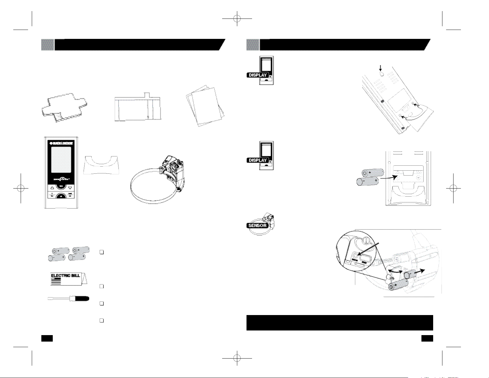
Digital Display Stand
Remove the battery compar tment cover on the
back of the Digital Display, insert two AA
batteries (not included) in the proper orientation,
and replace the battery compartment cover.
The Digital Display can be mounted to a wall using
the keyhole hanger in the back, or it can stand alone
using the plastic stand.
To attach the stand to the Digital Display, insert the plastic
tabs into the square recesses on the lower back of the Digital
Display as shown. Once all four tabs are in the recesses,
push up on the stand to lock it in place.
Keyhole Hanger
0 1 B E F ORE YOU BEGIN
4
Verify the contents of the box.
Verify that your package contains all of the components shown below. If any item is
missing, please call 1-800-544-6986.
1 Rubber Shim
3 Instruction
Manuals
(English, Spanish
and French)
Digital Display
Meter Sensor
(with clamping strap)
1 Clear Alignment
Template
You will also need:
Four (4) AA batteries (not included)
Do not use rechargeable batteries
Use lithium batteries in the sensor for best
performance in freezing temperatures (below 32°F, 0°C)
Copy of your Electricity Bill
1 large Flat Head Screwdriver (not included)
A clean damp cloth (not included)
Using a large Flat Head
Screwdriver, loosen the
slotted screw and open the Meter Sensor
battery compartment cover. Insert two AA
batteries (not included) in the orientation
indicated, then close the battery
compartment cover and tighten the screw
until snug.
About 10 seconds after installing the batteries,
the status indicator will light up solid red, and the
sensor will look for a signal from a meter. If the sensor is
not installed on a meter within 20 minutes, the status light will
blink rapidly. This is normal, and you can press the RESET button
to restart the search if your installation is interrupted.
Make sure that the battery closest to the Sensor Arm goes in with its positive end
(+) facing inward. Refer to (+) and (-) markings on the circuit board.
Install Meter Sensor Batteries
Install Digital
Display Batteries
Digital Display
Stand
Status
90539499 01 EM100B.qxd 7/7/08 10:05 AM Page 4
Page 4
Go to your electric meter and take the following
items with you:
• This Manual • A clean damp cloth
• Meter Sensor • 1 large Flat Head screwdriver
• Digital Display • Clear Alignment Template (if you have a Type 3 meter)
• Rubber Shim • A pen or pencil
Determine your electric meter type
In order to configure your Meter Sensor and program your Digital Display properly,
you must first determine what type of electric meter you have.
There are three types of electric meters:
0 3 I N S TALLING YOUR METER SENSOR
7
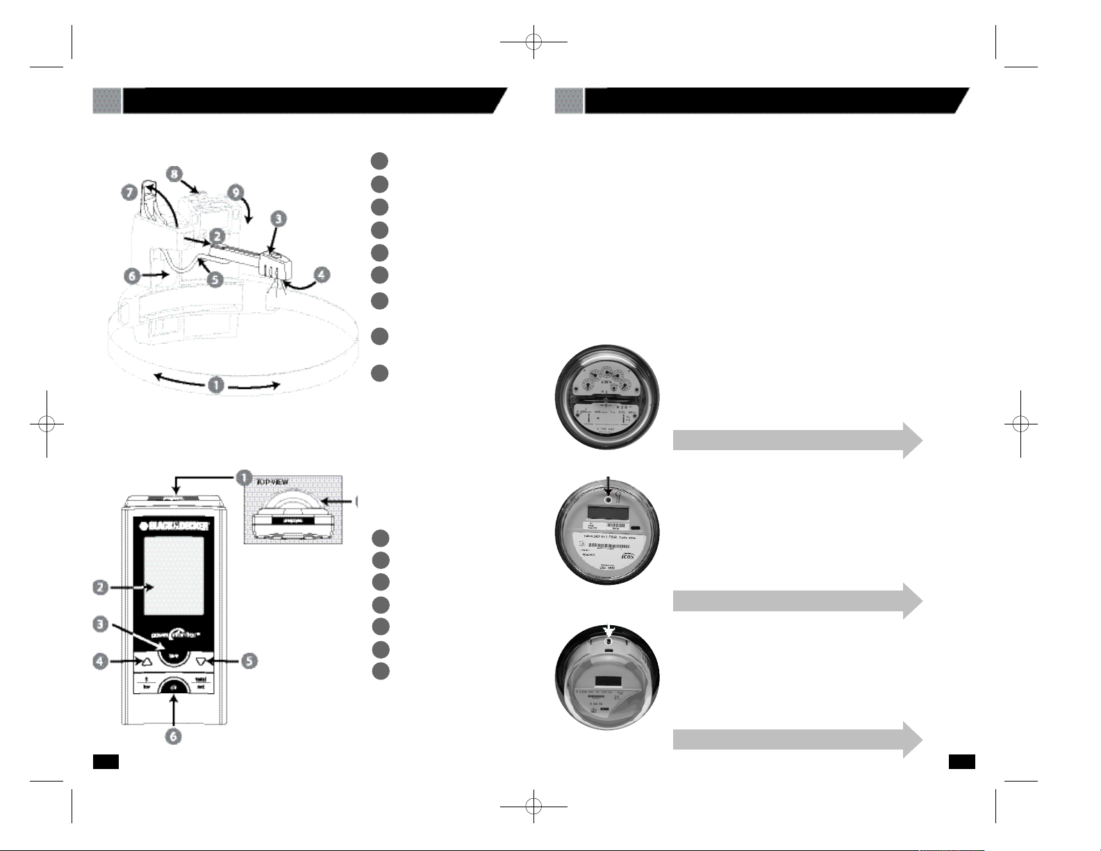
0 2 U N D E R S TANDING YOUR POWER MONITO R
6
Clamping Strap
Sensor Arm (extended)
Sensor Head
Sensor LEDs
Wire
Wire Cavity
Sensor Arm
Latch Cover
Battery Compartment
Latch
Battery Compartment
Cover
1
2
3
4
5
6
7
8
9
Knowing the Digital Display
prog/sync Button
Screen
tare Button
Increase Button
Decrease Button
clr Button
Display Stand
1
2
3
4
5
6
7
TYPE 1—Electromechanical
This type of meter has dials and a spinning disk.
Note – If your meter has dials, but the spinning disk is not
visible from the front of the meter, call the Black & Decker
Help Line at 1-800-544-6986.
TYPE 2—Electronic with optical port
on the face
The optical port looks like an LED, and may appear anywhere
on the face. Some meters have two ports.
TYPE 3—Electronic with optical
port on the top
The optical port looks like a clear plastic cylinder that
protrudes from the top of the electric meter.
Knowing the Meter Sensor
If this is your meter ty p e, proceed to the next page.
If this is your meter ty p e, proceed to page 10 .
If this is your meter ty p e, proceed to page 13 .
Optical Port
Optical Port
90539499 01 EM100B.qxd 7/7/08 10:05 AM Page 6
Page 5
9
0 3 I N S TALLING YOUR METER SENSOR
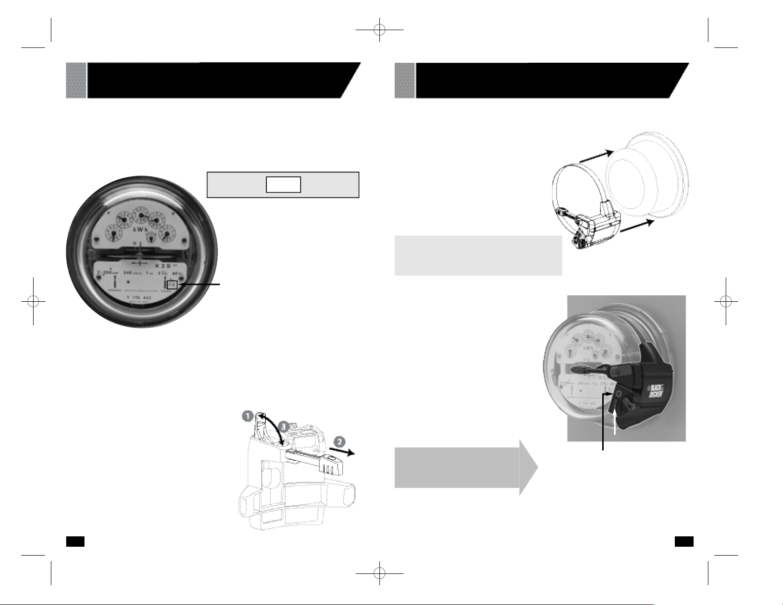
TYPE 1—ELECT R O M E C H A N I CA L
8
A . Record Your Meter’s Power F a c t o r
Find your meter’s Power Factor on the face of the meter. Look for a number preceded
by the letters Kh. This number is usually 7.2 for an electromechanical meter. Write this
number in the box below.You will need it later (in section 06) when you program your
Digital Display.
Power Factor = (usually 7.2 Kh)
Power Factor
C . Install Your Meter Sensor
1. Wipe the meter dome clean with the
damp cloth.
2 . Fit the Meter Sensor over your utility
m e t er as shown, so that the Sensor Head
sits as close as possible to the front of the
glass dome.
3 . Ti g h ten the clamping strap until the Mete r
Sensor is snu g, but can move just enough
to allow for slight adjustments.
4 . Position the Sensor A rm as shown to the
ri g h t .
N o t e : The Sensor A rm must be in line with
the disc (use the line of the Sensor A r m as
a re fe r ence) and the Sensor LEDs must be
c e n t e red from side-to - s i d e.
5 . Press the RESET bu tto n . Within 10
s e c o n d s , the STATUS indicator will light
solid red while the Meter Sensor looks
for a signal from the mete r.
6 . When you have positioned the sensor
a rm corre c t l y, the red STATUS indicato r
will flash whenever the bl a c k stripe on
the meter wheel passes by. You may
need to wait for seve r al revo l u t i o n s
b e f o re seeing the indicator fl a s h .
N OT E : To maximize batte ry life, the indicato r
s t ops flashing after about two minu t e s .
7. Ti g h t en the clamp just enough so that
the Meter Sensor cannot move.
B . Prepare Your Meter Sensor
Make sure the batteries are installed in the Meter Sensor (and the
STATUS Indicator is flashing).
1. Open the Sensor Arm Latch Cover by
pulling upward.
2. Extend the Sensor Arm to its full length by
pulling on it gently, but firmly. If you
accidentally pull it out completely, push it
back into the casing.
3. Close the Sensor Arm Latch Cover.
0 3 I N S TALLING YOUR METER SENSOR
TYPE 1—ELECT R O M E C H A N I CA L
Status Indicator
I n s t allation is complete! Go to
page 16 Section 4.
Reset Button
90539499 01 EM100B.qxd 7/7/08 10:05 AM Page 8
Page 6
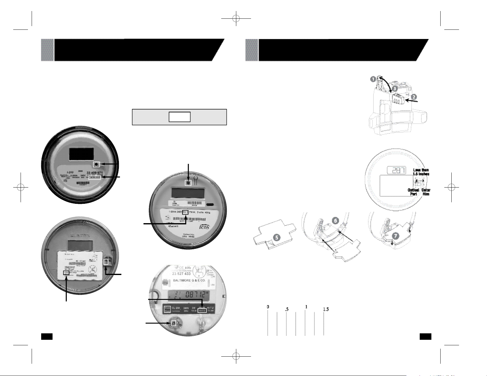
1110
A . Record Your Meter’s Power F a c t o r
Find and re c o rd your mete r’s Power Fa c t o r . On the face of the mete r , look for a number
p r eceded by the lette rs Kh, Ks, or Kt. This number is usually 1.0 for an electronic mete r. I f
your meter lists more than one of these nu m b e rs, look for the smallest nu m b e r. Wri te this
number in the box below. You will need it later (in section 06) when you pro g ram your Digita l
D i s p l a y.
Optical Port
Power Factor
Optical Port
Power Factor
Optical
Port
0 3 I N S TALLING YOUR METER SENSOR
TYPE 2—ELECTRONIC WITH OPTICAL PORT ON FAC E
0 3 I N S TALLING YOUR METER SENSOR
TYPE 2—ELECTRONIC WITH OPTICAL PORT ON FAC E
Ruler
Power
Factor
Optical Port (left port)
Power Factor
Power Factor = (usually 1.0 Kh)
B . Prepare Your Meter Sensor
Make sure the batteries are installed in the Meter
Sensor.
1. Pull the Sensor A rm Latch Cover upwa rd to open it.
2 . Ve rify that the Sensor A rm is pushed in as far as it
will go into the body of the Meter Sensor.
3 . Close the Sensor A r m Latch Cove r.
4 . Ve rify that the Sensor A rm is fully pushed in.
N o t e : If the optical port is closer than 1.5 inches to the
edge of the glass housing, you will need to add a ru bb e r
shim to the Sensor.
If the port is fa r ther than 1.5 inches from the edge, yo u
can skip steps 5-7.
5 . Peel off the adhesive backing from the shim.
6 . Position the shim on the underside of the Mete r
Sensor with the adhesive side dow n .
7. Press the shim in place onto the underside of the
M e t er Sensor body.
90539499 01 EM100B.qxd 7/7/08 10:05 AM Page 10
Page 7
C . Install Your Meter Sensor
1. Wipe the meter dome clean with the
damp cloth.
2. Fit the Meter Sensor over your utility
meter as shown, so that the Sensor
Head sits as close as possible to the
front of the glass dome.
3. Tighten the clamp until the Meter
Sensor is snug, but can move just
enough to allow for slight adjustments.
4. Position the Sensor Arm as shown to
the right:
Note: The LED at the end of the
Sensor Arm must be positioned directly
over the optical port on the meter.
5 . Press the RESET bu tto n . The STAT U S
I n d i c a t or will light solid red while the
M e t er Sensor looks for a signal from the
m e t e r.
6 . When you have positioned the Sensor
Head corre c t ly, the red STATUS Indicato r
s t a r ts flashing re g u l a rly, indicating that the
Sensor has dete c ted the signal from yo u r
m e t e r. Within one minu te, in addition to the
regular fl a s h i n g, you should see an ex t ra
flash now and then, depending on your
ra t e of electri c i ty consumption.These
ex t ra flashes are normal, and indicate
that the Sensor is reading the mete r’s
o u t p u t correctly.
N OT E : To maximize batte ry life, the indicato r
s t ops flashing after about two minu t e s .
7. Tighten the clamp just enough so that the
Meter Sensor cannot move.
1312
0 3 I N S TALLING YOUR METER SENSOR
TYPE 2—ELECTRONIC WITH OPTICAL PORT ON FAC E
Status Light Indicator
0 3 I N S TALLING YOUR METER SENSOR
TYPE 3—ELECTRONIC WITH OPTICAL PORT ON TO P
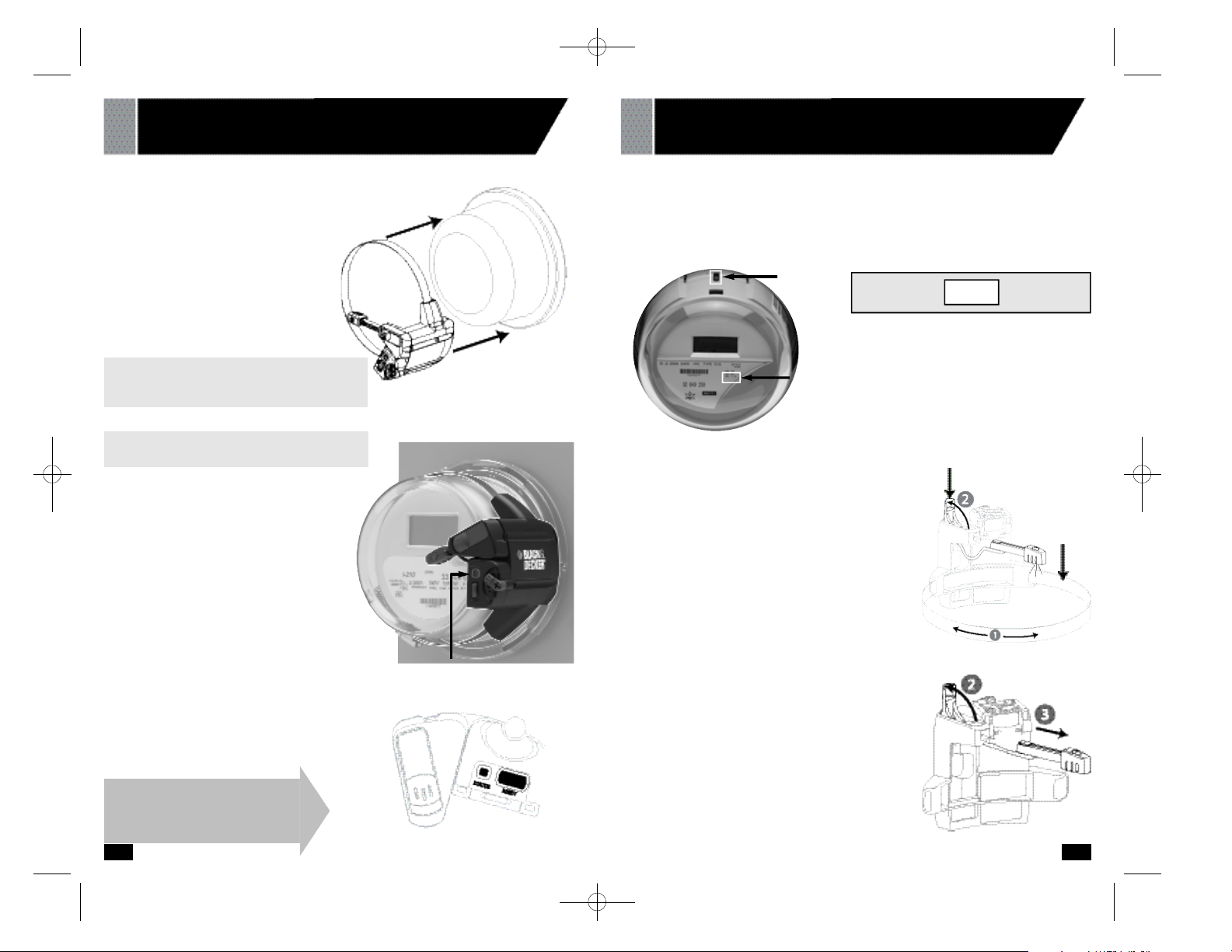
A . Record Your Meter’s Power F a c t o r
Find and re c o rd your mete r’s Power Fa c t o r. On the face of the mete r , look for a number
p r eceded by the lette r s Kh, Ks, or Kt.This number is usually 1.0 for an electronic mete r. If yo u r
m e t er lists more than one of these nu m b e r s, look for the smallest nu m b e r. Wri t e this number in
the box below.You will need it later (in section 06) when you pro gram your Digital Display.
Power Factor
B . Prepare Your Meter Sensor
Make sure the batteries are installed in the Meter Sensor.
For this type of mete r, you need to re c o n f i g u r e the Sensor.
1. Use a flat-head screwd ri ver to open the clamping strap
all the way until it opens. Re m o ve the strap from the
Sensor body.
2 . Pull the Sensor A rm Latch Cover up to unlock
the arm as shown (2).
3 . Pull the Sensor A rm complete ly out of the
body until it is complete ly detached, connecte d
o n l y by the wire (3). You may need to pull hard .
Optical
Port Power Factor = (usually 1.0 Kh)
I n s t allation is complete! Go to
Section 4.
Note: If your electric meter has two optical
ports, align the sensor with the one on the left.
Latch Cover
Clamping
Strap
90539499 01 EM100B.qxd 7/7/08 10:05 AM Page 12
Page 8

15
0 3 I N S TALLING YOUR METER SENSOR
TYPE 3—ELECTRONIC WITH OPTICAL PORT ON TO P
14
Status
Indicator
C . Install Your Meter Sensor
The objective of this step is to align the Sensor
LEDs dire c t l y over the optical port on the mete r.
1. S t and dire c t l y in front of your electric mete r, at
a height where you can see the optical port .
The optical port itself looks like a small
p r o t ruding pipe in the center of the top port i o n
of the electric mete r . Ca re f u l l y wipe the mete r
dome clean with the damp cloth.
2 . Peel the adhesive backing off of the te m p l a t e.
Hold the te m p l a te with the pro t ruding tab fa c i n g
you and the arrow pointing away from yo u .
3 . S t i ck the te m p l a te onto the meter with the
a r r ow pointing at, but not cove ring the optical
p o r t . You can peel the te m p l a te off the glass
and realign it if necessary.
4 . Align the edges of the sensor with the white
side lines on the te m p l a t e. Slide the Mete r
Sensor over the glass dome as far as it will go.
5 . Ti g h t en the clamp until the Meter Sensor
is snu g, but can move just enough to allow
for adjustments.
6 . Open the Sensor A rm Latch Cover and
look down the opening.Yo u ’ll see a ve rt i c a l
plastic tab painted white on the inside of the
Sensor body.
7. Look through the opening and confi rm that the
tip of the white plastic tab on the Sensor is
lined up with the arrow line on the te m p l a t e.
Adjust the position of the sensor if necessary.
8 . Press the RESET bu tto n . Within 10 seconds,
the STATUS indicator will light solid red while
the Meter Sensor looks for a signal from the
m e t e r. When the Sensor is corre c t ly aligned,
the Status indicator will bl i n k .
Reset
Button
4 . Tu rn the Sensor A rm so that the two Sensor
LEDs are visible (4). T h e y need to be able to see the
Optical Po rt on the mete r .
5 . Push the smaller end of the Sensor A r m upwa rds
t h r ough the latch opening and press the Sensor A rm
fi r m ly into the cavity (5).
6 . Slide the Sensor A rm as far down as it will go into the
b o ttom cavity of the body. If necessary, use a dull
p o i n t ed object, such as a ballpoint pen, to push it all the
way down (6). The two Sensor LEDs must be visibl e .
7. Tu c k the wire into the side cavity (7).
8 . Close the latch (8).
9 . Re t h read the clamping strap into the sensor
housing and re a t tach the ends. Tu r n the screw
as you feed in the end to re a ttach it.
Sensor LED’s
90539499 01 EM100B.qxd 7/7/08 10:05 AM Page 14
Page 9

Put Digital Display Beep!
into ID mode Beep!
Press and hold until
you hear two (2) beeps.
Reset Meter Sensor Press Beep!
Digital Display will beep.
Data will appear within
two (2) minutes.
05 DETERMINE BILLING MODE AND BILLING RAT E
17
04 SYNCHRONIZE METER SENSOR AND DIGITAL DISPLAY
16
In order to display the cost of your electricity, you need to program the Digital Display with
information from your electricity bill.
There are three ways you may be billed for electricity:
• Flat Rate. See example on page 1 8
You are charged the same amount per kilowatt-hour (kWh) no matter how much you
use or what time of day you use it.
• Tiered Rates. See example on page 2 0
You are charged one rate for an initial number of kilowatt-hours, then a higher rate if
you exceed that threshold. There may be several thresholds.
• Time-of-Use Rates. See example on page 2 3
You are charged a different rate depending on the time of day. There may be two rates
(on-peak and off-peak) or three rates (on-peak, mid-peak, and off-peak).
Get a recent electric bill and determine how you are charged.
Then, go to the appropriate page and fill out the form with
your billing information. This will make it easier to program your
Power Monitor.
If there is a problem, please read the Troubleshooting section in this Instruction Manual.
S T E P A C T I O N / P R E S S D I S P L AY
The prog/sync button on top of the Digital Display is used to enter
Program Mode and to enter data for each programming step.
The Reset Button is located on the front of the Meter
Sensor, adjacent to the Status Indicator.
Now, you can go indoors and, referring to your electric bill, program your billing
rates into the Digital Display.
The data appearing on your screen is an accurate measure of your electricity consumption. To see an accurate measure of your electricity cost, follow the next section to
program your billing rates.
If numbers are not appearing on your screen after 2 minutes, go to section 11,
Troubleshooting and Q&A.
0 3 I N S TALLING YOUR METER SENSOR
TYPE 3—ELECTRONIC WITH OPTICAL PORT ON TO P
9 . You may need to slide the Sensor towa r d you until
the Sensor LEDs are dire c t l y over the optical port on
the mete r.
If the STATUS indicator does not begin to blink within
one minu t e, continue to reposition the Sensor until
you have proper alignment.
N OT E : To maximize batte ry life, the indicator stops fl a s h i n g
a f ter about two minu t e s .
10 . When the STATUS light begins to blink, tighten the
clamping strap tight so the sensor cannot
m o ve. Close the latch.
I n s t allation is complete! Go to Section
4, Sy n c h r o n i z e Meter Sensor
.
Latch Raised
90539499 01 EM100B.qxd 7/7/08 10:05 AM Page 16
Page 10

05 DETERMINE BILLING MODE AND BILLING RAT E
19
05 DETERMINE BILLING MODE AND BILLING RAT E
18
Flat Rate Billing – Determine Your Billing Rate
Now refer to your own electric bill. Find your billing rate. If applicable, add fees and taxes
to your base rate to obtain an accurate total billing rate, as shown in the example.
If your rate is in dollars per kilowatt-hour ($/kWh), you will need to multiply by 100 to convert it to cents per kilowatt-hour (¢/kWh).
Billing Rate: = ¢/kWh
RECORD YOUR BILLING RATE HERE
Flat Rate Billing – Example
Note: Rates can differ
in winter and summer.
The sum of these rates is your total cost per
kilowatt-hour (kWh). In this example, add them
to get a total rate of $0.1348 per kilowatt-hour.
Then multiply by 100 to convert to 13.48 ¢/kWh
Billing Rate: = ¢/kWh
RECORD YOUR BILLING RATE HERE
13.48
Go to Section 6, Pro g ra m
D i g i t al Display.
90539499 01 EM100B.qxd 7/7/08 10:05 AM Page 18
Page 11

21
05 DETERMINE BILLING MODE AND BILLING RAT E
20
Tiered Rate Billing – Example
If you have tiered billing, you are charged an initial rate for an initial amount of power, or
tier; then a higher rate if you exceed that initial amount. Your billing plan may have several tiers.
You will need to determine the rate and threshold for each billing tier. Refer to the example below:
Example of a three-tier billing plan
Similar information will be available from your utility; call or consult their web site if this
information is not on your bill.
Power consumption,
kWh
(kilowatt-hours)
Threshold 1
1300 kWh
Threshold 2
2300 kWh
1300 kWh at
the lowest rate
1000 kWh at the
middle rate
400 kWh at the
highest rate
If your total
consumption is
2700 kWh…
…you will be
billed for:
Three rates, two thresholds
Generation charges per kWh 1300 kWh X $.0500 $ 65
Generation charges per kWh 1000 kWh X $.1000 $100
Generation charges per kWh 400 kWh X $.1500 $ 60
Transmission charges per kWh 1300 kWh X $.0200 $ 26
Transmission charges per kWh 1000 kWh X $.0500 $ 50
Transmission charges per kWh 400 kWh X $.0700 $ 28
Public benefits fees per kWh 1300 kWh X $.0050 $ 6.50
Public benefits fees per kWh 1000 kWh X $.0100 $ 10
Public benefits fees per kWh 400 kWh X $.0200 $ 6
TOTAL CHARGES $351.50
E L E C T R I C B I L L
Besides the
cost of the
electricity
itself, your bill
may have
additional
charges, fees,
and taxes
that are
linked to your
amount of
consumption
The lowest rate is the
Tier 1 rate.
Add all the Tier 1
charges to get a total of
$0.075/kWh.
Multiply by 100 to get
7.5¢/kWh.
The Tier 1 threshold is
1300 kWh.
The middle rate is the
Tier 2 rate.
Add all the Tier 2
charges to get a total of
$0.16/kWh.
Multiply by 100 to get
16¢/kWh.
The Tier 2 threshold is
1300 kWh + 1000 kWh
= 2300 kWh.
The highest rate is the
Tier 3 rate.
Add all the Tier 3
charges to get a total of
$0.24/kWh.
Multiply by 100 to get
24¢/kWh.
There is no threshold
for Tier 3.
For this example, you would record your billing data in the form like this:
Example bill for this three-tier billing plan:
Tier 1 ¢/kWh kWh
Tier 2 ¢/kWh kWh
Tier 3 ¢/kWh kWh
Tier 4 ¢/kWh kWh
Tier 5 ¢/kWh kWh
Tier 6 ¢/kWh kWh
RECORD YOUR BILLING RATES AND THRESHOLDS HERE
BILLING RATE THRESHOLD
7.5
16
24
1300
2300
- - -
90539499 01 EM100B.qxd 7/7/08 10:05 AM Page 20
Page 12

2322
05 DETERMINE BILLING MODE AND BILLING RAT E
Time-of-Use Rate Billing – Example
If you have Time of Use (TOU) billing, you are charged a different rate depending on the
time of day. There may be two rates (on-peak and off-peak) or three rates (on-peak, midpeak, and off-peak). In addition, weekends and holidays may be charged at a single rate
regardless of the time of day. The Power Monitor allows the entry of up to 6 time slots.
Example of a Time-of-Use billing plan:
Similar information will be available from your utility; call or consult their web site if this
information is not on your bill.
Off-Peak rates are in effect all hours on Saturday and Sunday, and on all holidays.
05 DETERMINE BILLING MODE AND BILLING RAT E
Tiered Rate Billing
Determine Your Billing Rates and Thresholds
Now refer to your own electric bill. Find your tiered billing rates, and the corresponding
threshold(s) in kilowatt-hours (kWh). If applicable, add fees and taxes to each tiered base
rate to obtain accurate total billing rates, as shown in the example.
If your rates are in dollars per kilowatt-hour ($/kWh), you will need to multiply by 100 to
convert them to cents per kilowatt-hour (¢/kWh).
Enter the Billing Rates and Thresholds from your electric bill in the table below.
The POWER MONITOR allows for up to six different tiered rates.
Tier 1 ¢/kWh kWh
Tier 2 ¢/kWh kWh
Tier 3 ¢/kWh kWh
Tier 4 ¢/kWh kWh
Tier 5 ¢/kWh kWh
Tier 6 ¢/kWh kWh
RECORD YOUR BILLING RATES AND THRESHOLDS HERE
BILLING RATE THRESHOLD
Go to Section 6, Pro g ra m
D i g i t al Display.
Boxed times need to be programmed into the Display.
- - -
90539499 01 EM100B.qxd 7/7/08 10:05 AM Page 22
Page 13

SLOT START TIME RATE TYPE
1
:
AM ON PEAK OFF PEAK
PM MID PEAK
2
:
AM ON PEAK OFF PEAK
PM MID PEAK
3
:
AM ON PEAK OFF PEAK
PM MID PEAK
4
:
AM ON PEAK OFF PEAK
PM MID PEAK
5
:
AM ON PEAK OFF PEAK
PM MID PEAK
6 AM ON PEAK OFF PEAK
PM MID PEAK
25
05 DETERMINE BILLING MODE AND BILLING RAT E
24
RECORD YOUR BILLING RATES AND TIME SLOTS HERE
OFF Peak Rate ¢/kWh
MID Peak Rate ¢/kWh
ON Peak Rate ¢/kWh
BILLING SCHEDULE
Time-of-Use billing applies to:
Weekdays
Weekends
7.5
24
16
X
7
10
8
11
- - -
- - -
X
X
X
X
Time-of-Use Rate Billing – Example
For the example, you would record your billing data as follows:
X
X
X
X
05 DETERMINE BILLING MODE AND BILLING RAT E
Time-of-Use Rate Billing – Example
Example bill for a three-rate Time-of-Use plan:
Generation charges per kWh 1300 kWh X $.0500 $ 65
Generation charges per kWh 1000 kWh X $.1000 $100
Generation charges per kWh 400 kWh X $.1500 $ 60
Transmission charges per kWh 1300 kWh X $.0200 $ 26
Transmission charges per kWh 1000 kWh X $.0500 $ 50
Transmission charges per kWh 400 kWh X $.0700 $ 28
Public benefits fees per kWh 1300 kWh X $.0050 $ 6.50
Public benefits fees per kWh 1000 kWh X $.0100 $ 10
Public benefits fees per kWh 400 kWh X $.0200 $ 6
TOTAL CHARGES $351.50
E L E C T R I C B I L L
Besides the
cost of the
electricity
itself, your bill
may have
additional
charges,
fees, and
taxes that are
linked to your
amount of
consumption.
The lowest rate is the
Off-Peak rate.
Add all the Off-Peak
charges to get a total of
$0.075/kWh.
Multiply by 100 to get
7.5 ¢/kWh
.
The middle rate is the
Mid-Peak rate.
Add all the Mid-Peak
charges to get a total of
$0.16/kWh.
Multiply by 100 to get
16 ¢/kWh.
The highest rate is the
On-Peak rate.
Add all the On-Peak
charges to get a total of
$0.24/kWh.
Multiply by 100 to get
24 ¢/kWh
.
90539499 01 EM100B.qxd 7/7/08 10:05 AM Page 24
Page 14

27
26
06 PROGRAM DIGITAL DISPLAY -
TIME, DAY,
T E M P E R ATURE, POWER FACTOR, BILLING MODE
The prog/sync button on top of the Digital Display is used to enter
Program Mode and to enter data for each programming step.
If the Digital Display detects no activity for one minute while in Program Mode, it will
automatically save your data and exit to Display Mode. Also, you can exit Program Mode
at any point by holding prog/sync for three seconds.
The buttons change the value on the screen. To make the numbers change faster,
you can hold the button down continuously until you reach the desired number.
If you enter a wrong value and accidentally save it, you can exit Program Mode. Then go
back into Program Mode and step through each entry until you get to the one you need to
fix. Any data you’ve already entered will be saved.
Follow these steps to program the Digital Display with your Power Factor (which you
recorded in section 03 Installing Your Meter Sensor), your Electric Bill information, and
display preferences.
Put Digital Display
into Program mode
Hold three seconds
until you hear one beep.
Set current time.
Set hours and AM/PM.
Set minutes.
Set clock for 12 Hr
(regular time) or
24 Hr (military time).
S T E P A C T I O N / P R E S S D I S P L AY
C o n t i n ue on the top of the next page.
Beep!
05 DETERMINE BILLING MODE AND BILLING RAT E
Time-of-Use Rate Billing
Determine Your Billing Rates and Time Slots
SLOT START TIME RATE TYPE
1
:
AM ON PEAK OFF PEAK
PM MID PEAK
2
:
AM ON PEAK OFF PEAK
PM MID PEAK
3
:
AM ON PEAK OFF PEAK
PM MID PEAK
4
:
AM ON PEAK OFF PEAK
PM MID PEAK
5
:
AM ON PEAK OFF PEAK
PM MID PEAK
6 AM ON PEAK OFF PEAK
PM MID PEAK
RECORD YOUR BILLING RATES AND TIME SLOTS HERE
OFF Peak Rate ¢/kWh
MID Peak Rate ¢/kWh
ON Peak Rate ¢/kWh
BILLING SCHEDULE
Time-of-Use billing applies to:
Weekdays
Weekends
Go to Section 6, Pro g ra m
D i g i t al Display.
Now refer to your own electric bill. Find your Time-of-Use billing rates, and the corresponding time slots. Also, determine if your Time-of-Use billing applies on weekends.
If applicable, add fees and taxes to each base rate to obtain accurate total billing rates, as
shown in the example.
If your rates are in dollars per kilowatt-hour ($/kWh), you will need to multiply by 100 to
convert them to cents per kilowatt-hour (¢/kWh).
Enter the Billing Rates and Time Slots from your electric bill in the table below.
The Power Monitor allows for two or three different Time-of-Use Rates and up to six
different Time Slots.
90539499 01 EM100B.qxd 7/7/08 10:05 AM Page 26
Page 15

2928
07 PROGRAM DIGITAL DISPLAY – FLAT RATE BILLING
Find the Billing Rate
you recorded in section 05.
Enter your Billing Rate.
To make the numbers change
faster, you can press and hold
the or .
Do NOT enter a threshold.
Press the button until you
see dashes appear on the
Digital Display.
Programming is complete!
S T E P A C T I O N / P R E S S D I S P L AY
Billing Rate: = ¢/kWh
RECORD YOUR BILLING RATE HERE
Go to Section 10, Using Yo u r
Power Monito r.
Set day of the week.
Set temperature units.
Find your Power Factor (the number you recorded in
section 03 Installing Your Meter Sensor).
Enter your Power Factor.
Typical Power
Factors are:
7.2 for electromechanical meters
1.0 for electronic meters with
optical ports
Enter your Billing Mode:
TIER
for Flat or Tiered rates
2-PEAK
for Time-of-Use with two rates
3-PEAK
for Time-of-Use with three rates
S T E P A C T I O N / P R E S S D I S P L AY
06 PROGRAM DIGITAL DISPLAY -
TIME, DAY,
T E M P E R AT U R E , P O WER FACTOR, BILLING MODE
If your billing mode is Flat Rate, p r oceed to section 07.
If your billing mode is T i e r ed Rate, p r oceed to section 08.
If your billing mode is Time-of-Use Rate, p r oceed to section 09.
Power Factor = (usually 7.2 Kh)
90539499 01 EM100B.qxd 7/7/08 10:05 AM Page 28
Page 16

08 PROGRAM DIGITAL DISPLAY –
TIERED RATE BILLING
Enter Billing Rate for Tier 1.
To make the numbers change
faster, you can press and hold
the or .
Enter Threshold 1.
Enter Billing Rate for Tier 2.
Enter Threshold 2.
If there is a Tier 3,
enter Billing Rate for Tier 3.
S T E P A C T I O N / P R E S S D I S P L AY
Note: Before you begin programming your Digital Display for Tiered Rate Billing,
you will need to refer to the Billing Rates and Thresholds you recorded in section 05.
C o n t i n ue on the top of the next page.
3130
08 PROGRAM DIGITAL DISPLAY –
TIERED RATE BILLING
If there is no Tier 3,
Press until you see dashes.
If you have additional tiers and
thresholds, continue to enter
Billing Rates for each tier and
enter each threshold.
Programming is complete!
S T E P A C T I O N / P R E S S D I S P L AY
Note: Before you begin programming your Digital Display for Tiered Rate Billing,
you will need to refer to the Billing Rates and Thresholds you recorded in section 05.
Go to Section 10, Using Yo u r
Power Monito r.
90539499 01 EM100B.qxd 7/7/08 10:05 AM Page 30
Page 17

33
32
09 PROGRAM DIGITAL DISPLAY –
TIME-OF-USE RATE BILLING
Select which Rate Type
applies to the first Time Slot.
Enter start time for second
Time Slot. Enter hours.
Then enter minutes.
/\ \/
Select which Rate Type
applies to the second Time Slot.
Continue this process to enter
data for all Time Slots from
your billing schedule in
section 05.
If you have fewer than 6 time
slots, hold down prog/sync to exit
Program Mode.
Programming is complete!
S T E P A C T I O N / P R E S S D I S P L AY
Note: Before you begin programming your Digital Display for Time-of-Use Rate Billing,
you will need to refer to the Billing Rates and Time Slots you recorded in section 05.
Go to Section 10, Using Yo u r
Power Monito r.
Beep!
09 PROGRAM DIGITAL DISPLAY –
TIME-OF-USE RATE BILLING
Select whether Time-of-Use
Billing applies on weekends.
Note: Flashing SUN and SAT
indicate Time-of-Use Billing
DOES NOT apply on weekends.
Enter Off-Peak Billing Rate.
To make the numbers change
faster, you can press and hold
the or .
For Three Rate (3-PEAK)
Billing only:
Enter Mid-Peak Billing Rate.
Enter On-Peak Billing Rate.
Enter start time for first
Time Slot. Enter hours.
Then enter minutes.
S T E P A C T I O N / P R E S S D I S P L AY
Note: Before you begin programming your Digital Display for Time-of-Use Rate Billing,
you will need to refer to the Billing Rates and Time Slots you recorded in section 05.
C o n t i n ue on the top of the next page.
90539499 01 EM100B.qxd 7/7/08 10:05 AM Page 32
Page 18

35
10 USING YOUR POWER MONITO R
34
Power Vi e w
The kilowatts currently consumed, updated every 30 seconds. This value
changes as you turn appliances on and off.
Bars move faster as consumption increases.
Displays either the total consumed energy since hitting clr, or an estimate of
your monthly energy use in kilowatt-hours.
For tiered or time-of-use billing, displays the tier or time slot.
Press to switch between Cost View and Power View.
Press to switch between Total Consumption and Estimated Monthly Consumption.
The Estimated Monthly Consumption is scaled from the Total Consumption.
Push and hold until the beep to clear the Total Consumption.
1
2
3
4
5
6
Press the $/kW button to cycle between Cost and Power views
7
10 USING YOUR POWER MONITO R
The Power Monitor will show you:
• Your current electricity usage
• The usage of a single electric appliance
• Your accumulated electricity usage over an hour, a day, or any time period
• Your estimated monthly usage
Press the $/kW button to cycle between Cost and Power views
Cost Vi e w
The cost per hour, updated every 30 seconds.
This value changes as you turn appliances on and off.
Bars move faster as consumption increases.
Displays either the total accumulated cost since hitting clr, or an estimate of your
monthly cost.
For tiered or time-of-use billing, displays the tier or time slot.
Press to switch between Cost View and Power View.
Press to switch between Total Cost and Estimated Monthly Cost. The Estimated
Monthly Cost is scaled from the Total Cost.
Push and hold until the beep to clear the Total Cost.
1
2
3
4
5
6
7
90539499 01 EM100B.qxd 7/7/08 10:05 AM Page 34
Page 19

3736
N o w , the Black & Decker Power Monitor is ready to
work for you.
Feedback on your electricity consumption will help you change your energy habits,
resulting in lower electricity bills. Many households have saved up to 20% off their
electricity bills by using the Power Monitor (see www.blackanddecker.com for more
information on these studies).
We recommend these steps after Power Monitor setup:
1. Use the TARE feature to measure the consumption of major appliances.
2. Show the device and your electricity bill to your children. Teach them how much it
costs to use the dishwasher, take a long shower, or leave lights on. You will
experience the greatest savings when your children learn along with you.
3. Place the Digital Display in a central location, such as the kitchen, where every
member of the family will see it and keep their energy consumption top-of-mind.
Checking the outside temperature is a great reason to look at it every day.
4. Make your home more energy efficient by sealing thermal leaks, adding insulation,
and replacing inefficient appliances. You can learn more about energy-related home
improvements from ENERGY STAR®, at www.energystar.gov
Typical power consumption for some household appliances:
Television 150 W
Microwave 1000-2000 W
Toaster 1000 W
Hot water heater 4000 W
Central air conditioner 2000–5000 W
My Appliances Cost:
Air conditioner/heat pump _ _ _ _ _ _ _ _ _ _ $/hr
Electric hot water heater for bath or shower _ _ _ _ _ _ _ _ _ _ $/hr
Dishwasher (note if energy-saving mode) _ _ _ _ _ _ _ _ _ _ $/hr
Electric stove _ _ _ _ _ _ _ _ _ _ $/hr
Microwave _ _ _ _ _ _ _ _ _ _ $/hr
Coffee maker _ _ _ _ _ _ _ _ _ _ $/hr
Clothes washer _ _ _ _ _ _ _ _ _ _ $/hr
Electric clothes dryer _ _ _ _ _ _ _ _ _ _ $/hr
Dehumidifier _ _ _ _ _ _ _ _ _ _ $/hr
Humidifier _ _ _ _ _ _ _ _ _ _ $/hr
Pool pump _ _ _ _ _ _ _ _ _ _ $/hr
Other Electrical Appliances:
_ _ _ _ _ _ _ _ _ _ _ _ _ _ _ _ _ _ _ _ _ _ _ _ _ _ _ _ _ _ _ _ _ _ _ _ _ _ _ _ _ _ _ _ _ _ $/hr
_ _ _ _ _ _ _ _ _ _ _ _ _ _ _ _ _ _ _ _ _ _ _ _ _ _ _ _ _ _ _ _ _ _ _ _ _ _ _ _ _ _ _ _ _ _ $/hr
_ _ _ _ _ _ _ _ _ _ _ _ _ _ _ _ _ _ _ _ _ _ _ _ _ _ _ _ _ _ _ _ _ _ _ _ _ _ _ _ _ _ _ _ _ _ $/hr
_ _ _ _ _ _ _ _ _ _ _ _ _ _ _ _ _ _ _ _ _ _ _ _ _ _ _ _ _ _ _ _ _ _ _ _ _ _ _ _ _ _ _ _ _ _ $/hr
10 USING YOUR POWER MONITO R
Measure the Consumption of a
Single Appliance with Ta r e
Note - If another appliance, like
a sump pump or refrigerator
compressor turns on while in
Tare mode, your measurement
will not be accurate.
Press the tare Button.
Turn on the appliance you
wish to measure.
The tare indicator is displayed
in the top row and, after a few
more minutes, the values
displayed represent the
energy currently consumed by
that particular appliance.
The display updates
every 30 seconds.
Press the tare button to return
to normal mode.
S T E P A C T I O N / P R E S S D I S P L AY
Note: Tare mode works in both Cost and Power views. Total consumption is
not affected by Tare mode.
The minimum power value the display can show is 0.1 kW (100 Watts).
Therefore, you might not be able to measure the consumption of a low-power
appliance, like a single light bulb.
90539499 01 EM100B.qxd 7/7/08 10:05 AM Page 36
Page 20

39
1 1 T R O U B L E S H O O TING AND Q&A
38
I am unsure of my electric meter type. How can I find out which type
of meter I have?
The photos in section 03 of the Instruction Manual show the various kinds of electric
meters that we have grouped under three types: electromechanical; electronic with optical
port on face; electronic with optical port on top.
The majority of existing meters fall under one of these generic types. Determine which
photo most closely matches your meter, and remember to follow the installation
instructions for that meter type. Also, find the meter’s Power Factor on the face of the
meter and write it in the box labeled “Power Factor.” The Power Factor is a number
(usually 1.0 or 7.2) preceded by two letters (usually Kh or Ks or Kt). Proceed with the
preparation steps in order and follow the installation instructions for that meter type.
After installing the Meter Sensor on my meter and pressing the RESET
button, nothing happens.The red indicator does not light up.
The STATUS light in the Sensor should light up solid red within 10 seconds after
pressing the RESET switch. If it does not, try these steps:
1. Confirm that the batteries are inserted in the correct orientation. + and – symbols are
printed on the green circuit board inside the battery compartment.
2. Confirm that the batteries are not dead. We recommend lithium batteries for longer life
in freezing conditions.
3. Confirm that the battery lid is closed and screwed down. The lid has to be fastened
down for the batteries to make contact.
The red STATUS indicator on my Meter Sensor is flashing rapidly, and
I cannot proceed with the installation as described.
The fast flashing indicates that the Meter Sensor has not received a signal from the
meter, or can not see the rotating meter wheel, after 20 minutes of trying. Follow the
steps in Section 3 to make sure the Sensor is properly aligned on your meter.
Then press the RESET button. The indicator will turn off and light up again after 10
seconds. You can then proceed with the installation normally.
My Meter Sensor STATUS LED is flashing regularly, but every now and
then, there is an extra flash. Is there anything wrong with my unit?
This is exactly what you should see. Electronic meters produce one single pulse every
time you have consumed one watt-hour. When the Meter Sensor first detects a pulse from
an electronic meter, the STATUS indicator starts flashing. Thereafter, the indicator keeps
on flashing at the same frequency. In addition, it will flash once every time it reads a pulse
from your meter, at intervals that vary according to your current rate of electricity
consumption. This periodic irregular flashing is absolutely normal.
When I try to synchronize my Digital Display and Meter Sensor, the Digital
Display keeps showing “id” on the screen.
This indicates that the Digital Display is in ID mode, meaning that it is searching for your
Meter Sensor. Press the RESET button on the Meter Sensor. If the Digital Display remains
in ID mode, move it to a location between 2 and 10 feet (60 cm to 3m) of the Meter
Sensor, and then press the RESET button again.
The power usage shown on the Digital Display is low or does not match
what it should be.
You may have entered the wrong Power Factor (Kh), which calibrates the Digital Display
A.
B.
C.
D.
E.
F.
1 1 T R O U B L E S H O O TING AND Q&A
Dashes and loss of the animated bars indicate the Digital Display has lost contact
with the sensor. The battery may be dead or it may be too far away.
If contact with the Meter Sensor is lost, the Digital Display goes to sleep to save
battery life. Change Meter Sensor batteries or move closer to the electric meter,
then press any button to wake up and try to regain contact.
Indicates batteries need to be replaced in the Meter Sensor or the Digital Display.
1
2
3
90539499 01 EM100B.qxd 7/7/08 10:05 AM Page 38
Page 21

41
1 1 T R O U B L E S H O O TING AND Q&A
40
My Digital Display is showing SLEEP and dashes. What do I do?
This indicates that the Digital Display is not receiving transmissions from the Meter
Sensor, and the Display has gone to sleep to save battery life. Press any button on the
Display to wake it up. If the Display does not show data within two minutes, try these
steps, in order:
1. Move the Display closer to the Sensor. The Power Monitor has a range of about 60 ft.
(20 m), including transmission through an exterior wall. The range may be less if there
are metal walls or beams between the Sensor and the Display. Also, the range may
decrease as the batteries in the Sensor lose power, or in extremely cold weather. We
recommend lithium batteries for the Sensor if the temperature falls below freezing.
2. Inspect the Meter Sensor. Make sure that the batteries are not dead, and that the
Sensor is still properly aligned on the meter. Press the RESET button on the Sensor. The
STATUS light should light up solid, then begin flashing slowly (once per revolution for an
electromechanical meter). Refer to Section 3 if you need to re-align your Sensor.
3. Re-synchronize the Sensor and the Display. Bring the Display to within 2 feet of the
Sensor. Press and hold the prog/sync button on the Display until you hear two beeps and
the Display says “id”. Then press and hold the RESET button on the Sensor for 6
seconds. When you release the RESET button, the Display should beep, and “id” will
disappear. After two minutes, the Display should show data.
The power usage shown on my Digital Display is not updating or is
unusually low.
Try turning on an electric appliance that consumes a large amount of power such as a
stove or dryer. If the values on the Digital Display do not start to update within a few
minutes, then the Meter Sensor is likely not aligned correctly on your utility meter. Try
repeating the appropriate alignment steps described in the Instruction Manual.
The temperature shown on the Digital Display does not match weather reports
or appears to be incorrect.
The temperature shown on the Digital Display is the ambient temperature at your utility
meter; it may vary from other sources, such as TV weather reports, because of distance
and other factors. Also, if your utility meter is exposed to direct sunlight during any part of
the day, then the reading will be higher than normal. The reading will return to the correct
value when the utility meter is in the shade.
My Digital Display behaves erratically and shows illogical values.
Should your Digital Display start displaying any unexpected values, reset it to the factory
settings by pressing on the prog/sync and clr keys simultaneously. However, doing so will
erase all your existing rate entries and you will have to follow the instructions in this
Instruction Manual to set up and program your Digital Display again.
The total shown on my Digital Display does not match the total shown on
my electricity bill.
In order for the two totals to match, you would need to clear the totals on the Digital
Display on the exact day and time the utility company reads your meter. In addition, your
electricity bill may include fixed fees or taxes that are not proportional to your electric
usage. The total amount shown on the Power Monitor is accurate, but is really meant as a
reference to indicate how much power you have consumed since you last cleared the
totals. For example, if you clear the totals at the beginning of every monthly cycle, then
you can use the Power Monitor to compare against your monthly budget.
J.
K.
L.
M.
N.
1 1 T R O U B L E S H O O TING AND Q&A
to your electric meter. Use the tare feature to measure the consumption of your microwave
or toaster, and compare the value on the Digital Display to the value marked on the
nameplate of the appliance. If the numbers are off by a factor of 2 or more, you need to
change the Power Factor. Refer to section 03 in the Instruction Manual. Go out to your
electric meter and confirm the Power Factor (sometimes labeled Ks or Kt). On some larger
homes, there may be a sticker on the meter indicating that your utility has changed the
meter's Power Factor. Then, follow the programming instructions to enter a new value into
the Digital Display.
The consumption information shown on my Digital Display is not correct
and it jumps randomly.
S eve r al fa c to r s can affect the accura cy of the info rmation shown on your Digital Display and
t h e y all re l a te to inte r fe r e n c e . If your neighbor also has a Power Monitor sys tem, you may b e
receiving their info rm a t i o n . In this case, you need to change the Meter Sensor address and
re - sy n c h r o n i z e the Digital Display. Repeat section 04 in the Instruction Manual, but press a n d
hold the RESET bu tton for fi ve (5) seconds.The Meter Sensor then selects a new addre s s
ra n d o m ly on which to base the sy n c h ro n i z a t i o n . Wi reless dev i c e s, such as weather s tations or
o l d - s tyle baby monito r s and cordless phones, transmit info r mation on fre q u e n c i e s similar to the
Power Monito r . If you have a wireless weather station, try turning it off bri e fly and check to see
if the Power Monitor Display re t u rns to normal opera t i o n . If it does, then check to see if yo u
can change the weather sta t i o n’s operating channel.
The Sensor Battery indicator shows a low battery level, but I installed fresh
batteries not long ago.
Regular alkaline batteries can become exhausted very rapidly when it is extremely cold
outside. If you are expecting an extended period of temperatures below 32°F (0°C), try
using lithium type AA batteries in the Meter Sensor. These batteries are commonly
available wherever you can buy batteries and they provide better performance in cold
weather.
The Meter Sensor appears to have detected my meter properly, but I only
see dashes (--) on my Digital Display.
This indicates that the Digital Display is not receiving transmissions from the Meter Sensor. Try
these ste p s, in ord e r:
1. M o ve the Display closer to the Sensor. The Power Monitor has a range of about 60 ft .
(20 m), including transmission through an ex te rior wa l l . The range may be less if there are
m e t al walls or beams between the Sensor and the Display. A l s o , the range may decre a s e
as the batte ries in the Sensor lose powe r, or in ex t re m e l y cold we a t h e r. We recommend
lithium batte rie s for the Sensor if the te m p e r a t u r e falls below fre e z i n g .
2 . Inspect the Meter Sensor. M a k e sure that the batte ries are not dead, and that the Sensor
is still pro p e rly aligned on the mete r. Press the RESET bu t ton on the Sensor. The STAT U S
light should light up solid, then begin flashing slow ly (once per revolution for an electro
mechanical mete r ) . Re f er to Section 3 if you need to re-align your Sensor.
3 . Re - s y n c h ro n i z e the Sensor and the Display. B ring the Display to within 2 feet of the
S e n s o r. Press and hold the pro g / sync bu tton on the Display until you hear two beeps and
the Display says “ i d ”. Then press and hold the RESET bu t ton on the Sensor for 6 seconds.
When you release the RESET bu tton, the Display should beep, and “ i d ” will disappear.
A fter two minu te s , the Display should show data .
G.
H.
I.
90539499 01 EM100B.qxd 7/7/08 10:05 AM Page 40
Page 22

43
13 T E C H N I C AL SPECIFICAT I O N S
42
Power
Display 2 AA Alkaline Batteries (LR6 or equivalent)
Sensor 2 AA Alkaline Batteries (LR6 or equivalent)
2 AA Lithium Batte r ies for te m p e r a t u r es consiste n t l y
b e l o w 32°F (0 °C )
Wireless Communications
Frequency 433.92MHz
Update Rate Approximately every 30 seconds
Range Up to 60 ft. (20m) through a single external wall
Operating Temperature Range
Display 50°F to 113°F (10°C to 45°C) . For indoor use only
Sensor -40°F to 140°F (-40°C to 60°C)
Performance
Minimum power measurement 300W
Power Resolution 100W
Cumulative Energy Measurement error <2% for electromechanical meter
<0.2% for electronic meter
FCC INFORMATION
FCC Class B Part 15
This device complies with part 15 of the FCC Rules.
This equipment has been tested and found to comply with the limits for a Class B digital
device, pursuant to part 15 of the FCC Rules. These limits are designed to provide
reasonable protection against harmful interference in a residential installation. This
equipment generates, uses, and can radiate radio frequency energy and, if not installed
and used in accordance with the instructions, may cause harmful interference to radio
communications. However, there is no guarantee that interference will not occur in a
particular installation. If this equipment does cause harmful interference to radio or
television reception, which can be determined by turning the equipment off and on, the
user is encouraged to try to correct the interference by one or more of the following
measures:
• Reorient or relocate the receiving antenna.
• Increase the separation between the equipment and receiver.
• Connect the equipment into an outlet on a circuit different from that to which the
receiver is connected.
• Consult the dealer or an experienced radio/TV technician for help.
Industry Canada Certification
Operation is subject to the following two conditions:
• This device may not cause harmful interference, and
• This device must accept any interference received, including interference that may
cause undesired operation.
1 2 H O W ELECTRICITY IS MEASURED
How Electricity is Measured
Power is the ability to do work. Electric power is measured in Watts (W), and for large
values, in kilowatts (1000 Watts, or kW). A typical incandescent light bulb consumes 60
Watts. A typical microwave oven consumes 1 to 2 kilowatts.
Energy is power used over a period of time. Electric energy is measured in kilowatt-hours
(kWh). If you leave a 60W light on for one hour, it consumes 60 Watt-hours, or 0.06 kWh.
If you leave a 2 kW microwave oven on for 15 minutes, it consumes 0.5 kWh.
13 T E C H N I C AL SPECIFICAT I O N S
Service Information
Black & Decker offers a full net work of company-owned and authorized service locations
throughout North America. All Black & Decker Service Centers are staffed with trained
personnel to provide customers with efficient and reliable power tool service.
Whether you need technical advice, repair, or genuine factory replacement parts, contact
the Black & Decker location nearest you.
To find your local service location, refer to the yellow page directory under "Tools—
Electric" or call: 1-800-544-6986.
90539499 01 EM100B.qxd 7/7/08 10:05 AM Page 42
Page 23

44
See ‘Tools-
Electric’
– Yellow Pages –
for Service & Sales
Imported by
Black & Decker (U.S.) Inc.,
701 E. Joppa Rd.
Towson, MD 21286 U.S.A.
Catalog Number EM100B Part No. 90539499 Rev. 1 JUN. 2008
Copyright 2008 Black & Decker (US) Inc. Printed in China
Full Tw o - Year Home Use Wa r r a n t y
Black & Decker (U.S.) Inc. warrants this product for two years against any defects in
material or workmanship. The defective product will be replaced or repaired at no charge
in either of two ways.
The first, which will result in exchanges only, is to return the product to the retailer from
whom it was purchased (provided that the store is a participating retailer). Returns should
be made within the time period of the retailer’s policy for exchanges (usually 30 to 90
days after the sale). Proof of purchase may be required. Please check with the retailer for
their specific return policy regarding returns that are beyond the time set for exchanges.
The second option is to take or send the product (prepaid) to a Black & Decker owned or
authorized Service Center for repair or replacement at our option. Proof of purchase may
be required. Black & Decker owned and authorized Service Centers are listed under
"Tools-Electric" in the yellow pages of the phone directory and on our website
www.blackanddecker.com.
This warranty does not apply to accessories. This warranty gives you specific legal rights
and you may have other rights which vary from state to state. Should you have any
questions, contact the manager of your nearest Black & Decker Service Center. This
product is not intended for commercial use.
90539499 01 EM100B.qxd 7/7/08 10:05 AM Page 44
 Loading...