

Page 1

Commercial/Industrial Use Warranty
ELU warrants this product for one year from date of purchase. We will
repair without charge, any defects due to faulty material or workmanship. Please
return the complete unit, transportation prepaid, to any Black & Decker Service
Center or Authorized Service Station listed under “Tools Electric" in the yellow
pages. This warranty does not apply to accessories or damage caused where
repairs have been made or attempted by others.
Like most Black & Decker products your tool is listed by Underwriters
Laboratories to ensure that it meets stringent safety requirements.
This symbol on the nameplate means the product is listed by Underwriters
Laboratories, Inc.
WOODWORKING TOOLS BY
BIACK&OECKER Form No. 741396
BLACK & DECKER (U.S.) INC., U.S. Power Tools Group, 10 North Park Drive, P.O. 798, Hunt Valley, MD 21030-0798 U.S.A.
(NOVEMBER92) ©1987 Printed in U.S.A.
080 04 00 04
nstriitiii iian
3 1/8" Planer
3375
Page 2
TIanfcs for
Black & Decker offers a selection
of replacement blades and other
accessories to enhance the versatility
of your planer. Visit your local Black &
Decker Service Center where
recommended accessories can be
purchased.
If you should need assistance in
locating recommended accessories
for your tool, contact;
Black & Decker (U.S.) Inc.
User Services Department
10 North Park Drive
P.O. Box 857
Hunt Valley, MD 21030-0857
Recommended accessories for
your tool are available at extra cost
from your local Black & Decker
Service Center. The use of any other
accessories or attachments may be
hazardous. If you have any questions
concerning which accessories are
recommended, contact Black &
Decker at the above address.
All bearings used are factory
lubricated to last the life of the
bearings.
buying an ELU
Planer.
Your new ELU planer is a
tough, reliable and hard working
professional just like you’d expect
from Black & Decker. Every inch
the pro that you are, your planer is
a precision tool capable of
producing exceptionally smooth
and precise surfaces.
It’s ELU dependable so you
can count on it time and time again
to produce first class results that
WOODWORKING TOOLS BY
BmCK&DECKEH
you’ll be proud of.
Please take the time to read
this informative instruction manual
and pay particular attention to the
safety rules we’ve provided for your
protection.
Don’t forget to send in your
owner’s registration card.
Thanks, again for buying Black
& Decker!
After every use of the tool, make
sure the tool is cleaned out with an air
hose and free of all debris.
To assure product SAFETY and
RELIABILITY, repairs, maintenance
and adjustment, (including brush
inspection and replacement) should
be performed by qualified service
organizations, always using ELU
replacement parts.
ELU tools are serviced by Black &
Decker Company owned Service
Centers.
Page 3

Side Fence
Safety Cover
The planer is equipped with an
adjustable side fence to assist you in
planing long pieces. A safety cover
mounted to the side fence covers all
of the planer blade that is not being
used to plane. Assemble the side
fence and safety cover as shown in
Figure 7.
NOTE; When using the whole
width of the blade for planing, as
shown in Figure 8. the safety cover
need not be installed; it will not cover
any portion of the blade in this situation.
Fence Adjustment
UNPLUG PLANER
The side fence is secured in the
front bore. Mount the fence as shown
in (Fig. 8), and use it to guide the
planer along the edge of the wood,
NOTE; In order for the fence to
perform properly , the edge of the
wood must be flat and at 90° from the
surface being planed.
NOTE; For proper rabbeting, it is
necessary to use fence. Refer to (Fig.
10),
Rabbeting
Install the Depth Stop and secure
it using the Depth Stop Knob. (Both of
these parts are in the plastic bag
packed with your planer.)
UNPLUG PLANER
To set depth of rabbet, loosen
knob “A”, set depth stop "B" to
desired dimension (Measure from
bottom of fixed shoe, to bottom of
depth stop). Tighten knob “A" (Fig. 9).
Before doing any finishing work, make
several practice cuts on scrap lumber
until you feel comfortable with the
planer and rabbeting guide.
(Remember that several shallow cuts
are better than one deep cut).
Maximum rabbeting depth is 27/32"
(22mm). Maximum removal in one pass
is 1 /8" (3mm) therefore several cuts
will be required to obtain maximum
rabbeting depth of 27/32" (22mm).
Adjustment of
Rabbet Width
For proper rabbeting, it is
necessary to use the fence. Refer to
(Fig. 10). Adjust to desired cutting
width by loosening fence clamping
knob, move fence to preferred setting,
then retighten knob.
Edge Chamfering
Your planer has a precision
machined groove in the center of the
front of the shoe for planing along the
edge of the wood. Here, again, it’s a
good idea to try a piece of scrap wood
before doing finish work. (Fig. 11).
How To Change
And Adjust
RIades
For best results, always use sharp
blades. Check for damaged blades
and replace as necessary.
Replacement blades are available at
your local Black & Decker Service
Center.
NOTE: Blades are dual edged
and reversible for extended cutting
life.
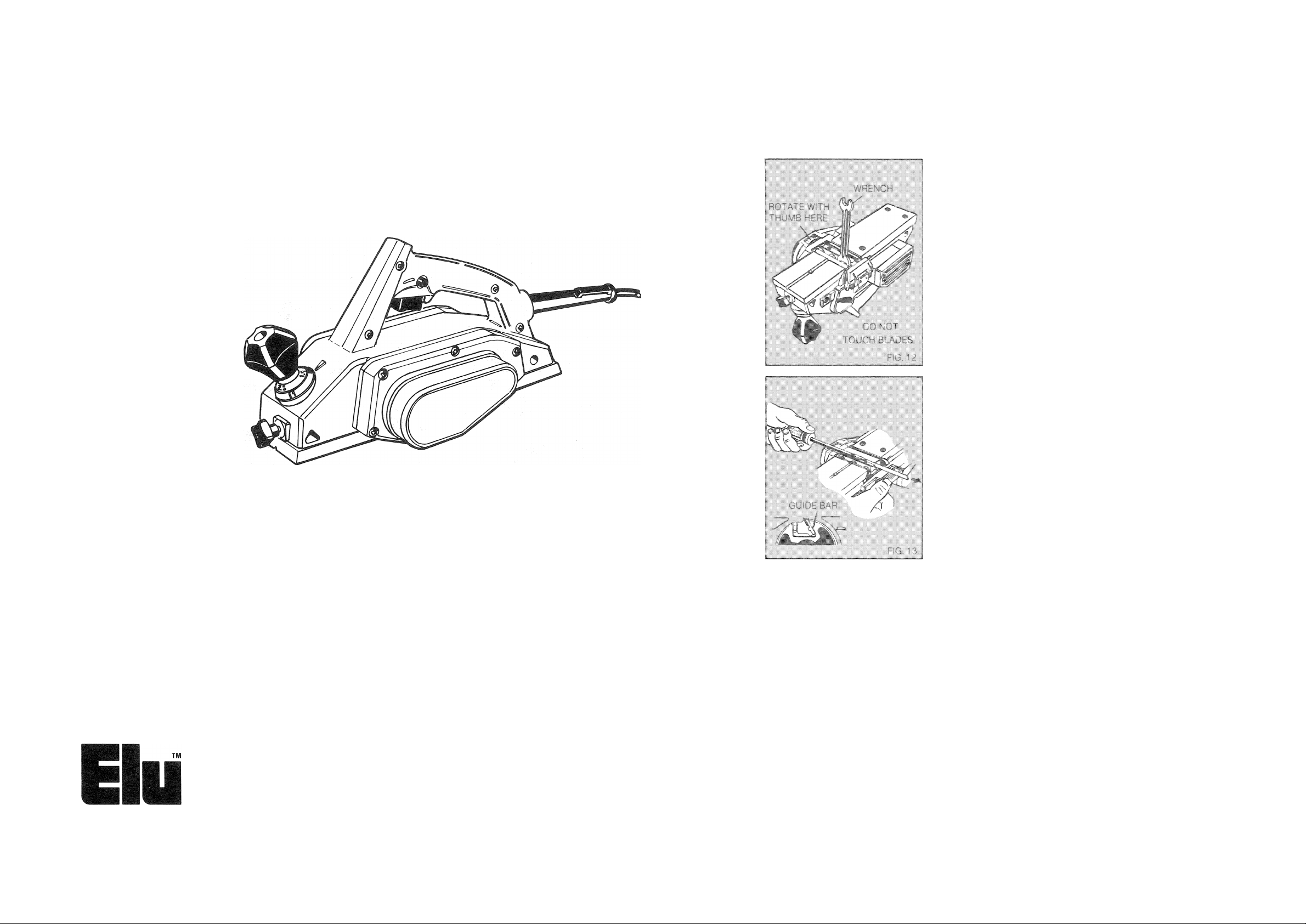
TO CHANGE BLADES
1. Unplug the planer.
2 Loosen the three hex head bolts
with the wrench provided. (Fig. 12).
3. Slide blade out with screwdriver
and turn over or replace with new
blade. CAUTION: When changing
blades, do not remove guide bar
from drum. See (Fig. 13).
4. Rotate drum by hand, as shown in
Figure 12, to make sure blade does
not interfere with housing. Check
both sides.
5. Alternately tighten 3 hex head bolts
gradually until secure. This
procedure prevents misalignment
of blade due to clamping forces.
6. Repeat procedure for blade #2.
7. Before doing any finish work, make
a few cuts on scrap lumber to
assure blades are properly
installed.
WARNING: When using Electric Tools, basic safety precautions should always be followed to
reduce risk of fire, shock, and personal injury, including the following:
READ ALL INSTRUCTIONS
KEEP WORK AREA CLEAN. Cluttered areas and benches invite injuries.
CONSIDER WORK AREA ENVIRONMENT. Don’t expose power tools to rain. Don’t
use power tools in damp or wet locations. Keep work area well lit.
GUARD AGAINST ELECTRIC SHOCK. Prevent body contact with grounded surfaces.
For example: pipes, radiators, ranges, refrigerator enclosures.
KEEP CHILDREN AWAY. All visitors should be kept away from work area. Do not let
visitors contact tool or extension cord.
STORE IDLE TOOLS. When not in use, tools should be stored in dry, and high or
locked-up place—out of reach of children,
DON’T FORCE TOOL. It will do the job better and safer at the rate for which it was
intended.
USE RIGHT TOOL. Don’t force small tool or attachment to'do the job of a heavy-duty
tool. Don’t use tool for purpose not intended, for example, don’t use circular saw for cutting
tree limbs or logs.
DRESS PROPERLY. Do not wear loose clothing or jewelry. They can be caught in
moving parts. Rubber gloves and non-skid footwear are recommended when working
outdoors. Wear protective hair covering to contain long hair.
USE SAFETY GLASSES. Also use face or dustmask if cutting operation is dusty.
9.
DON’T ABUSE CORD. Never carry tool by cord or yank it to disconnect from receptacle.
10,
Keep cord from heat, oil, and sharp edges.
11.
SECURE WORK. Use clamps or a vise to hold work. It’s safer than using your hand and it
frees both hands to operate tool.
DON’T OVERREACH. Keep proper footing and balance at all times.
12,
MAINTAIN TOOLS WITH CARE. Keep tools sharp and clean for better and safe
13.
performance. Follow instructions for lubricating and changing accessories. Inspect tool
cords periodically and if damaged have repaired by authorized service facility. Inspect
extension cords periodically and replace if damaged. Keep handles dry, clean, and free
from oil and grease,
14.
DISCONNECT TOOLS. When not in use, before servicing, and when changing
accessories, such as blades, bits, cutters,
REMOVE ADJUSTING KEYS AND WRENCHES. Form habit of checking to see that
15,
keys and adjusting wrenches are removed from tool before turning it on.
AVOID UNINTENTIONAL STARTING. Don’t carry plugged-in tool with finger on
16.
switch. Be sure switch is off when plugging in.
17,
OUTDOOR USE EXTENSION CORDS. When tool is used outdoors, use only extension
cords intended for use outdoors and so marked.
ST AY ALERT. Watch what you are doing. Use common sense. Do not operate tool when
18.
you are tired.
19.
CHECK DAMAGED PARTS. Before further use of the tool, a guard or other part that is
damaged should be carefully checked to determine that it will operate and perform its
intended function. Check for alignment of moving parts, binding of moving parts, breakage
of parts, mounting, and any other conditions that may affect its operation. A guard or other
part that is damaged should be properly repaired or replaced by an authorized service
center unless otherwise indicated elsewhere in this instruction manual. Have defective
switches replaced by authorized service center. Do not use tool if switch does not turn it
on and off.
DO NOT OPERATE portable electric tools near flammable liquids or in gaseous or
20,
explosive atmospheres. Motors in these tools normally spark, and the sparks might ignite
fumes.
SAVE THESE INSTRUCTIONS
Page 4

TRIGGER SWITCH
Additional
Operating
Instructions
PRECAUTIONARY
INSTRUCTIONS
1. CAUTION—Blades are
extremely sharp. Avoid body
contact.
2. Read owner’s manual thoroughly
before using tool.
3. Voltage must agree with specific
data on the nameplate.
4. Be sure the switch is in “OFF”
position before connecting tool to
power supply.
5. Switch tool “OFF” immediately if
tool should become jammed in
work.
6. Be sure tool is disconnected from
power source when cleaning,
adjusting, or doing maintenance
on the tool.
7. Planer should be properly set and
adjusted before turning unit on.
8. Use specified replacement parts
only.
9. Maintain tool with care. Follow
instructions for changing blades.
10. Store tool in a clean dry place
after disconnecting from power
source.
11. Do not force tool, allow tool to
perform as it was designed. Use
only sharp blades.
12. Do not allow visitors to approach
work area, especially children.
13. Do not cover the air vents on the
tool. Vents must be kept open for
motor cooling.
14. Do not leave tool unattended
without disconnecting from power
source.
15. Do not yank cord when
disconnecting tool from power
supply.
16. Do not carry the tool by power
cord.
17. Do not carry planer with your
finger on the switch.
18. Do not lay tool down on shoe
when the blades are exposed.
19. Do not allow planer blade to
contact metal objects. This may
chip or damage blades.
NOTE—Do not use chipped or
damaged blades.
20. Do not obstruct side chip chute.
21. Always use fence unless surface
planing. Use extreme caution,
stay clear of drive belt and cutter
location.
22. Turn off tool immediately after
finishing cut.
SAVE THESE INSTRUCTIONS
SHOE ADJUSTMENT
KNOB
Double Insulation
Your unit is DOUBLEINSULATED to give you added
safety. This means that it is
constructed throughout with TWO
separate “layers” of electrical
insulation or one DOUBLE thickness
of insulation between you and the
tool’s electrical system.
Tools built with this insulation
system are not intended to be
grounded. As a result, your tool is
equipped with a two-prong plug which
permits you to use extension cords
without concern for maintaining a
ground connection.
NOTE; DOUBLE INSULATION
does not take the place of normal
safety precautions when operating
this tool. The insulation system is for
added protection against injury
resulting from a possible electrical
insulation failure within the tool.
CAUTION: When servicing all
tools. USE ONLY IDENTICAL
REPLACEMENT PARTS. Repair or
replace damaged cords.
FENCE
ROD TIGHTENING
KNOB
FRONT BORE
Extension Cords
Double insulated tools have 2 wire cords, and can be used with 2 wire or 3
wire extension cords. Only round jacketed extension cords should be used, and
we recommend that they be listed by Underwriters Laboratories (U.L.). If the
extension will be used outside, the cord must be suitable for outdoor use. Any
cord marked as outdoor can also be used for indoor work. The letters “WA” on
the cord jacket indicate that the cord is suitable for outdoor use.
An extension cord must have adequate wire size (AWG or American Wire
Gauge) for safety, and to prevent loss of power and overheating. The smaller
the gauge number of the wire, the greater the capacity of the cable, that is 16
gauge has more capacity than 18 gauge. When using more than one extension
to make up the total length, be sure each individual extension contains at least
the minimum wire size.
To determine the minimum wire size required, refer to the chart below;
CHART FOR MINIMUM WIRE SIZE (AWG) OF EXTENSION CORDS
NAMEPLATE
RATING-AMPS
0-10.0
10.1 - 13.0
13.1 - 15.0
Before using an extension cord, inspect it for loose or exposed wires,
damaged insulation, and defective fittings. Make any needed repairs or replace
the cord if necessary.
TOTAL EXTENSION CORD LENGTH-FEET
25 50 75 100 125 150 175 200
14 12 12
18
16
14
16
18
14 14
16
14 12
14
16
14 12 12 12
12 12
12
12
UNPLUG PLANER
The adjustment of the desired
depths is accomplished by turning
shoe adjustment knob.
First, set the planing depth to zero
by placing a straight edge along the
bottom of the tool and adjusting the
front shoe until the front and stationary
shoes are of equal height (Fig. 3), (At
this point, no light will pass between
the shoes and the straight edge.)
When both the adjustable shoe
and the stationary shoe are even, the
adjusting knob should read zero on
the lower scale, as shown in Figure
3A. From that starting point, rotate the
adjusting knob clockwise to raise the
adjustable shoe. Each full revolution of
Your ELU tool IS powered by an
ELU-built motor. Be sure your power
supply agrees with the nameplate
marking.
Volts 50/60 Hz or “AC only”
means your tool must be operated
only with alternating current and never
with direct current.
Voltage decrease of more than
10% will cause loss of power and
overheating. All ELU tools are factory
tested; if this tool does not operate,
check the power supply.
Switch
Always pick up your planer by the
handle before depressing the switch.
NOTE; Always remember to keep free
hand away from bottom of planer. The
planer IS started by depressing the
trigger in the handle. To turn the
planer off, release the trigger (Fig. 1),
Allow time for the blades to stop
turning before setting the tool down.
To lock the planer “ON” squeeze
the trigger and hold it while you press
in the trigger locking button in the
lb
—
handle next to the trigger. Hold the
locking button in while you release the
trigger and the tool will continue to
run. To release the trigger lock,
squeeze and release the trigger once.
------
the adjusting knob raises the shoe
1/16” (1.5 mm) and the scale on the
knob is marked in .5 mm graduations.
On the first revolution of the knob,
read the graduations on the bottom of
the knob and on the second
revolution, read the upper graduations,
as shown in Figure 3A. When you
have adjusted the planer, practice on
a piece of scrap wood until you are
comfortable with the tool.
SHOE f
KNOBJ
fV'X M
With one hand holding the handle,
place the front shoe on the work,
making certain blades are not
touching the work. Put pressure on the
handle so that the front shoe is
absolutely flat on the work (Fig. 4).
Start to plane with motor running at full
speed. NOTE; Several shallow
passes will produce a smoother
surface than one deep one.
In the beginning and in the end of
planing, be especially careful to keep
your planer flat on the work (Fig. 5 & 6).
A ■ . . ■/.
 Loading...