

Page 1
WOODWORKSPti TOOLS BY
BIACK&DECKER
Instruction Manual
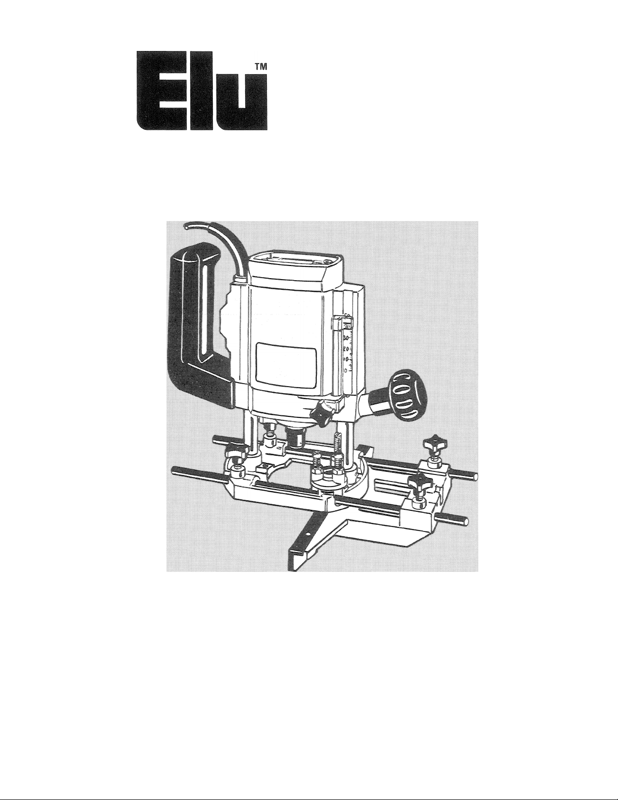
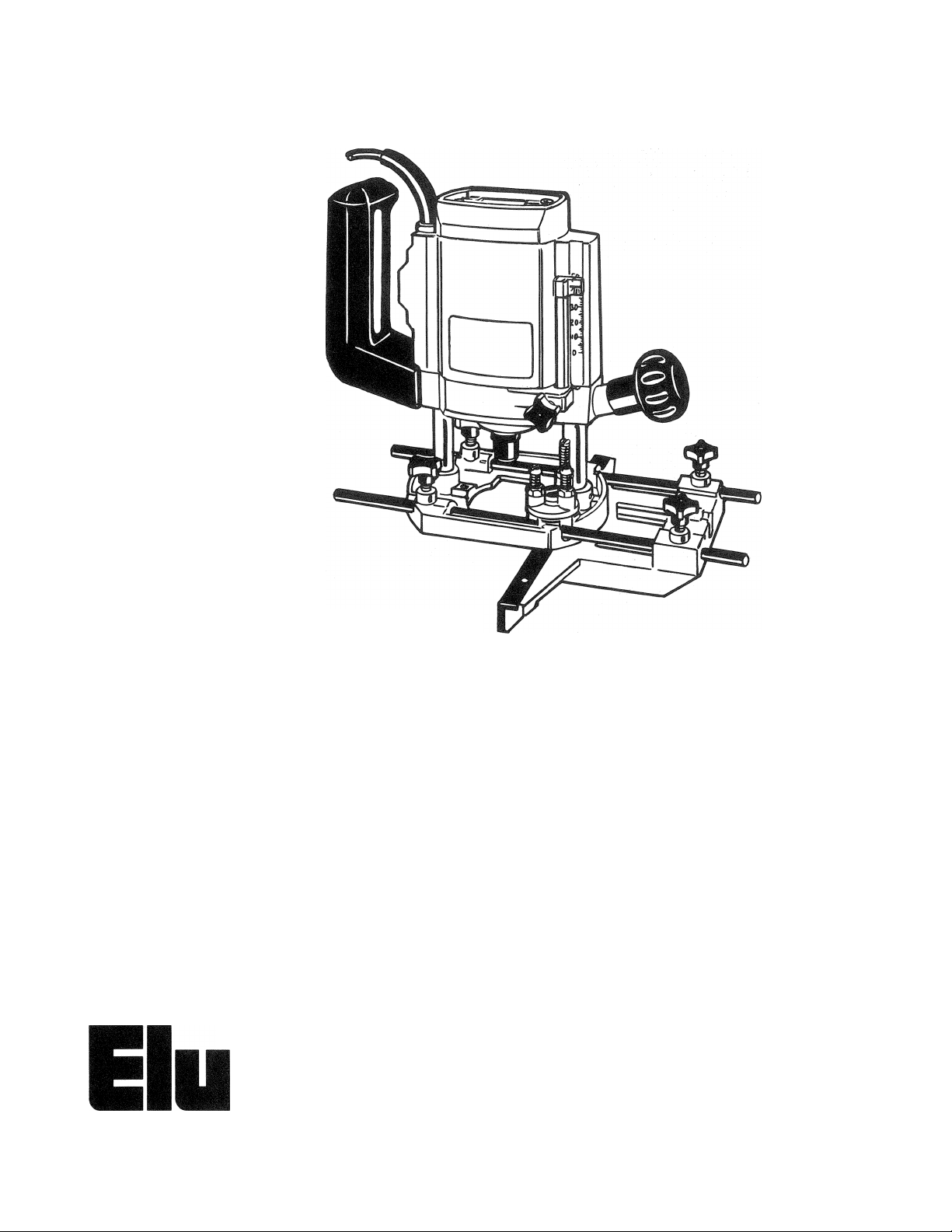
Plunge Cut Routers
3303,3304
Page 2
Thanks for
buying an ELU
Plunge Cut Router.
If you already own an ELU
power tool, you know the pleasures
of working with a real pro. Built to
ELU’s traditional standards for high
quality and durability and backed
by Black & Decker’s extensive
service network, you’ve got an
excellent value that will serve you
well for years to come.
im
WOODWORKING TOOLS BY
BIACK&DEGKEII
Please take the time to read
this informative manual and pay
particular attention to the safety
rules we've provided for your
protection.
Don’t forget to send in your
owner’s registration card.
Thanks again for buying Black
& Decker!
Page 3

Important Safety Instructions
WARN ING: When using Electric Tools, basic safety precautions should always be followed to
reduce risk of fire, shock, and personal injury, including the following:
READ ALL INSTRUCTIONS
1. KEEP WORK AREA CLEAN. Cluttered areas and benches invite injuries.
2. CONSIDER WORK AREA ENVIRONMENT. Don’t expose power tools to rain. Don’t
use power tools in damp or wet locations. Keep work area well lit.
3. GUARD AGAINST ELECTRIC SHOCK. Prevent body contact with grounded surfaces.
For example: pipes, radiators, ranges, refrigerator enclosures.
4. KEEP CHILDREN AWAY. All visitors should be kept away from work area. Do not let
visitors contact tool or extension cord.
5. STORE IDLE TOOLS. When not in use, tools should be stored in dry, and high or
locked-up place—out of reach of children.
6. DON’T FORCE TOOL. It will do the job better and safer at the rate for which it was
intended.
7. USE RIGHT TOOL. Don’t force small tool or attachment to do the job of a heavy-duty
tool. Don’t use tool for purpose not intended, for example, don’t use circular sawfor cutting
tree limbs or logs.
8. DRESS PROPERLY. Do not wear loose clothing or jewelry. They can be caught in
moving parts. Rubber gloves and non-skid footwear are recommended when working
outdoors. Wear protective hair covering to contain long hair.
9. USE SAFETY GLASSES. Also use face or dustmask if cutting operation is dusty.
10. DON’T ABUSE CORD. Never carry tool by cord or yank it to disconnect from receptacle.
Keep cord from heat, oil, and sharp edges,
11. SECURE WORK. Use clamps or a vise to hold work. It’s safer than using your hand and it
frees both hands to operate tool.
12. DON’T OVERREACH. Keep proper footing and balance at all times.
13. MAINTAIN TOOLS WITH CARE. Keep tools sharp and olean for better and safe
performance. Follow instructions for lubrioating and changing accessories. Inspect tool
cords periodically and if damaged have repaired by authorized service facility. Inspect
extension cords periodically and replace if damaged. Keep handles dry, clean, and free
from oil and grease.
14. DISCONNECT TOOLS. When not in use, before servicing, and when changing
accessories, such as blades, bits, cutters.
15. REMOVE ADJUSTING KEYS AND WRENCHES. Form habit of checking to see that
keys and adjusting wrenches are removed from tool before turning it on.
16. AVOID UNINTENTIONAL STARTING. Don’t carry plugged-in tool with finger on
switch. Be sure switch is off when plugging in.
17. OUTDOOR USE EXTENSION CORDS. When tool is used outdoors, use only extension
cords intended for use outdoors and so marked.
18. ST AY ALERT. Watch what you are doing. Use common sense. Do not operate tool when
you are tired.
19. CHECK DAMAGED PARTS. Before further use of the tool, a guard or other part that is
damaged should be carefully checked to determine that it will operate and perform its
intended function. Check for alignment of moving parts, binding of moving parts, breakage
of parts, mounting, and any other conditions that may affect its operation. A guard or other
part that is damaged should be properly repaired or replaced by an authorized service
center unless otherwise indicated elsewhere in this instruction manual. Have defective
switches replaced by authorized service center. Do not use tool if switch does not turn it
on and off.
20. DO NOT OPERATE portable electric tools near flammable liquids or in gaseous or
explosive atmospheres. Motors in these tools normally spark, and the sparks might ignite
fumes.
SAVE THESE INSTRUCTIONS
Page 4
Double Insulation
Your unit is DOUBLE-
INSULATED to give you added
safety. This means that it is
constructed throughout with TWO
separate "layers” of electrical
insulation or one DOUBLE thickness
of insulation between you and the
tool’s electrical system.
Tools built with this insulation
system are not intended to be
grounded. As a result your unit is
equipped with a two-prong plug which
permits you to use extension cords
without concern for maintaining a
ground connection.
NOTE: DOUBLE INSULATION
does not take the place of normal
safety precautions when operating
this tool. The insulation system is for
added protection against injury
resulting from a possible electrical
insulation failure within the tool.
CAUTION: When servicing all
tools. USE ONLY IDENTICAL
REPLACEMENT PARTS. Repair or
replace damaged cords.
Motor
Your ELU tool is powered by an
ELU-built motor. Be sure your power
supply agrees with the nameplate
marking.
Volts 50/60 Hz or "AC only”
means your tool must be operated
only with alternating current and never
with direct current.
Voltage decrease of more than
10% will cause loss of power and
overheating. All ELU toos are factory
tested; if this tool does not operate,
check the power supply.
Extension Cords
Double insulated tools have 2 wire cords, and can be used with 2 wire or 3
wire extension cords. Only round jacketed extension cords should be used, and
we recommend that they be listed by Underwriters Laboratories (U.L.). If the
extension will be used outside, the cord must be suitable for outdoor use. Any
cord marked as outdoor can also be used for indoor work. The letters "WA” on
the cord jacket indicate that the cord is suitable for outdoor use.
An extension cord must have adequate wire size (AWG or American Wire
Gauge) for safety, and to prevent loss of power and overheating. The smaller
the gauge number of the wire, the greater the capacity of the cable, that is 16
gauge has more capacity than 18 gauge. When using more than one extension
to make up the total length, be sure each individual extension contains at least
the minimum wire size.
To determine the minimum wire size required, refer to the chart below.
CHART FOR MINIMUM WIRE SIZE (AWG) OF EXTENSION CORDS
NAMEPLATE
RATING-AMPS
0-10.0 18
10.1 -13.0
13.1 - 15.0
Before using an extension cord, inspect it for loose or exposed wires,
damaged insulation, and defective fittings. Make any needed repairs or replace
the cord if necessary.
TOTAL EXTENSION CORD LENGTH-FEET
25 50 75 100 125 150 175 200
14
18 16 16
16 16
14
14
14 14 14 12 12
12 12
14
12
12
12 12
12
12
—
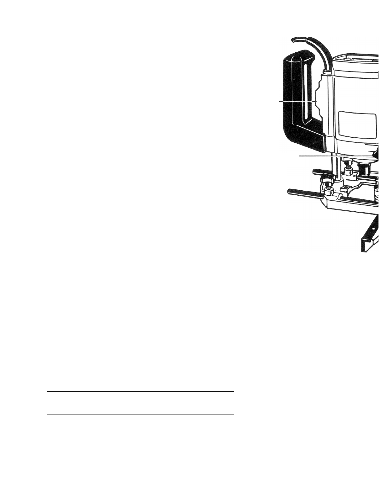
Switch
Depth Bar
Clamp Screw
Special
Instructions For
Electronic Router
Cat. #3304
You have just purchased a
portable router which incorporates a
state of the art electronic motor
control. The control system governs
the motor to give you easy start-up,
smooth cutting, and higher power
output. These unique capabilities give
you a router which is responsive to
your needs.
The electronic motor control
system has two basic features (Fig. 1 ).
A. Ramp start - when you turn on the
router, you will notice that it does
not have the jerk from the rapid
acceleration of the motor. This
router has a starting circuit which
accelerates the motor up to speed
smoothly, without jerking, and
allows you to maintain easier
control of the router during the
start-up period.
Page 5
> \G \
в. Constant speed cutting - as you
load the router, the selected cutting
speed does not slow down during
normal use. The electronic control
governs the motor and gives you a
consistent finish to your work. Only
under very heavy loading will the
speed of the unit fall below the
governed speed.
To set the router speed (from
8,000 RPM to 24,000 RPM) rotate the
speed control wheel shown in Figure
1. The higher the number the higher
the speed. The numbers on the wheel
are for reference only and do not
indicate any particular speed.
The lower the speed setting, the
slower the router runs. Lower speed
settings may be useful for making fine
cuts in softer materials, where control
of the unit may be of greater
importance.
Router bits larger than 1 /4"
diameter are not recommended when
routing soft woods on the lowest
speed setting.
Operating
Instructions For
The Router
PREPARATION FOR USE
The motor in this router is
relatively high-powered (750 Watts,
max.). Despite this, it is advisable to
cut deep grooves or remove large
amounts of material in two or more
passes.
TECHNICAL DATA
Model
Voltage
Speed
Insulation
Column
Plunging stroke
Routing depth
Cutter
mounting
Cutter cap
routing
Rotary depth
stop
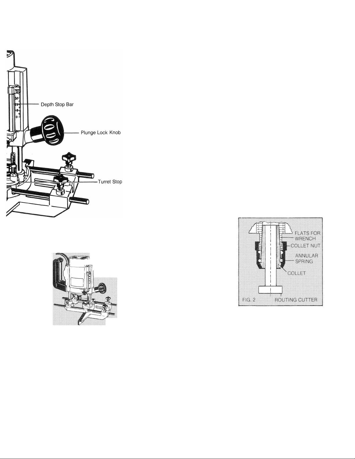
IMPORTANT NOTE
NEVER TIGHTEN COLLET
NUT IF THERE IS NO CUTTER IN
THE COLLET. COMPRESSING
COLLET TOO MUCH MIGHT
RESULT IN IT BEING DAMAGED.
TO CHANGE COLLET
THE COLLET IS SECURED IN
THE COLLET NUT BY MEANS OF
THE ANNULAR SPRING. A
STRONG PULL WILL RELEASE
THE COLLET FROM THE NUT
THE NEW COLLET SHOULD
THEN BE INSERTED IN THE NUT
AND BE PUSHED IN.
3303, 3304
120
24,000 r.p.m,
double
insulated
spring loaded
twin column
50 mm
(1-15/16")
0-50 mm
adjustable
precision collet,
size 1 /4"
max. 30 mm
(1-3/16")
(shallow)
3 stage depth
position
INSTALLING ROUTER BITS
(TURN OFF AND UNPLUG
ROUTER)
To install a router bit, first open
the collet by loosening
(counterclockwise) the collet nut, Use
the supplied wrenches if necessary.
Insert the shaft of the desired bit into
the collet as far as it will go and then
pull it out about 1 /16". Hold the router
shaft with one of the wrenches and
firmly tighten the collet nut with the
other.
Reverse the process to remove
bits. Always be sure to turn off and
unplug the router when installing or
removing bits.
CAUTION; Router Bits Are Sharp
... Use Care In Handling Them.
The front face of the collet must
always be flush with the face of the
nut. If this is not the case, remove the
assembly from the machine and press
the collet into the collet nut so that it is
held by the spring with the faces flush.
SETTING DEPTH OF CUT USING
DEPTH STOP (FIG. 3)
(TURN OFF AND UNPLUG
ROUTER)
Loosen the Depth Bar Clamp
Screw and the Plunge Lock Knob.
Push the router down until the cutter
contacts the workpiece and tighten
the Plunge Lock Knob.
Raise the Depth Stop Bar until the
distance between the lower end of the
bar and the selected screw in the
Turret Stop is equal to the desired
depth of cut. Tighten the Depth Bar
Clamp Screw and loosen the Plunge
Lock Knob. (The tool will spring up.)
The depth of cut will be equal to
the distance between the head of the
bolt on the turret stop and the end of
the depth stop bar. The depth of cut
can be gauged by using the
graduated scale.
Page 6

When several cuts are to be
made at different depths in the
material, the three bolts on the turret
stop are adjusted accordingly.
NOTE: The Turret Stop can be
adjusted so that the Depth Stop Bar
does not contact any screw head. To
adjust any screw in the Turret Stop,
use the wrench supplied and loosen
the lock nut. Turn the screw as
desired and retighten the lock nut.
The Depth Stop Bar can be
removed from the tool for free hand
cutting.
hJ
-------—KNOB
FIG. 3 TURRET STOP
LOCK
Switch
TO SWITCH ON THE MACHINE
The switch positions are
indicated by red markings on and off.
Note: Always pull the plug on the
cord set out of its receptacle when
changing a cutter or fitting the
accessories in order to avoid any
chance of an accident.
GENERAL (FIGS. 4, 5, 6. 7)
All common routing tasks can be
performed with ease with the Plunge
Cut Router; Grooving, rabbeting,
recessing, veining, and profiling on all
types of wood and plastic.
Always feed the router opposite
to the direction in which the cutter is
rotating.
The router should be moved in a
clockwise direction when working
round a template, or routing free-hand.
Only carbide-tipped cutters
should be used on panels faced with
plastic laminates.
ROUTER UPiN(. U.vr.. AMAND GUÍO:. sMiM: ;
S DUG NCI
Accessories
Black & Decker offers a wide
array of router bits and other
accessories to enhance the versatility
of your router. Visit your local Black &
Decker Service Center where
recommended accessories can be
purchased.
If you need assistance in locating
recommended accessories for your
tool, contact:
Black & Decker (U.S.) Inc.
User Services Department
10 North Park Drive
P.O. Box 857
Hunt Valley, MD 21030-0857
Recommended accessories for
your tool are available at extra cost
from your local Black & Decker
Service Center. The use of any other
accessories or attachments may be
hazardous. If you have any questions
concerning which accessories are
recommended, contact Black &
Decker at the above address.
Operation
After setting the cutting depth as
described on page 5, locate the router
such that the bit is directly over the
place you will be cutting. With the
router running, lower the unit smoothly
down into the workpiece. (DO NOT
JAM THE ROUTER DOWN) When
the tool reaches the pre-set depth,
tighten the Plunge Lock Knob. When
you have finished routing, loosen the
knob and let the spring lift the router
directly out of the workpiece.
Important
To assure product SAFETY and
RELIABILITY, repairs maintenance
and adjustment, (including brush
inspection and replacement) should
be performed by qualified service
organizations, always using ELU
replacement parts.
ELU products are serviced by
Black & Decker company owned
Service Centers.
Page 7

Page 8

Commercial/Industrial Use Warranty
ELL) warrants this product for one year from date of purchase. We will
repair without charge, any defects due to faulty material or workmanship. Please
return the complete unit, transportation prepaid, to any Black & Decker Service
Center or Authorized Service Station listed under 'Tools Electric” in the yellow
pages. This warranty does not apply to accessories or damage caused where
repairs have been made or attempted by others.
Like most Black & Decker products your tool is listed by Underwriters
Laboratories to ensure that it meets stringent safety requirements.
This symbol on the nameplate means the product is listed by Underwriters
Laboratories, Inc.
WOODWORKING TOOLS BY
B1ACKS.DECKER Form No, 741388
BLACK & DECKER (U.S.) INC., U.S. Power Tools Group, 10 North Park Drive, P.O. 798, Hunt Valley, MD 21030-0798 U.S.A.
(JULY87) ©1987 Printed in Switzerland
096 04 00 09
 Loading...