


www.blackanddecker.ae
CS355

ENGLISH
N
M
G
E
D
L
K
J
H
F
I
A
G
2

ENGLISH
O
N
M
C
B
G
E
D
L
F
Fig. 2
E
K
J
G
Fig. 1
H
I
Fig. 3
A
F
E
F
I
Fig. 4
H
3

ENGLISH
Fig. 5
Q
E
Fig. 7
P
F
L
E
D
R
P
Q
J
U
Fig. 8
T
S
Fig. 6
Fig. 9
4
W
V

ENGLISH
Intended use
Your Black & Decker Chop Saw has been
designed for the cutting of variously shaped
steel materials. This product is intended for
consumer use only.
Safety instructions
General power tool safety warnings
Warning! When using power tools,
always observe the safety regulations
applicable in your country to reduce the risk of
fire, electric shock and personal injury.
• Read all of this manual carefully before using
the appliance.
• The intended use is described in this manual.
The use of any accessory or attachment or
the performance of any operation with this
appliance other than those recommended in
this instruction manual may present a risk of
personal injury.
• Retain this manual for future reference.
1. Keep work area clean
Cluttered areas and benches can cause
accidents.
2. Consider work area environment
Do not expose the tool to rain. Do not use the
tool in damp or wet conditions. Keep the work
area well lit (250 - 300 Lux). Do not use the tool
where there is a risk of causing fire or explosion,
e.g. in the presence of flammable liquids and
gases.
3. Guard against electric shock
Prevent body contact with earthed surfaces (e.g.
pipes, radiators, cookers and refrigerators).
When using the tool under extreme conditions
(e.g. high humidity, when metal swarf is being
produced, etc.), electric safety can be further
improved by using a highsensitivity 30 mA
Residual Current Device (RCD).
4. Keep other persons away
Do not let persons, especially children, not
involved in the work touch the tool or the
extension cord and keep them away from the
work area.
5. Store idle tools
When not in use, tools must be stored in a dry
place and locked up securely, out of reach of
children.
6. Do not force the tool
It will do the job better and safer at the rate for
which it was intended.
7. Use the right tool
Do not force small tools to do the job of a heavy
duty tool. Do not use tools for purposes not
intended; for example do not use circular saws to
cut tree limbs or logs.
8. Dress properly
Do not wear loose clothing or jewellery, as these
can be caught in moving parts. Wear protective
hair covering to keep long hair out of the way.
When working outdoors, preferably wear suitable
gloves and non-slip footwear.
9. Use protective equipment
Always use safety glasses. Use a face or dust
mask whenever the operations may produce
dust or flying particles. If these particles might be
considerably hot, also wear a heat-resistant
apron. Wear ear protection at all times. Wear a
safety helmet at all times.
5

ENGLISH
10. Connect dust extraction equipment
If devices are provided for the connection of
dust extraction and collection facilities, ensure
that these are connected and properly used.
11. Do not abuse cord
Never carry the tool by its cord. Never pull the
cord to disconnect from the socket. Keep the
cord away from heat, oil and sharp edges.
12. Secure workpiece
Use clamps or a vice to hold the workpiece. It is
safer and it frees both hands to operate the tool.
13. Do not overreach
Keep proper footing and balance at all times.
14. Maintain tools with care
Keep cutting tools sharp and clean for better
and safer performance. Follow instruction for
lubricating and changing accessories. Inspect
tool cords periodically and if damaged have
them repaired by an authorized service facility.
Inspect extension cords periodically and replace
if damaged. Keep handles dry, clean and free
from oil and grease.
15. Disconnect tool
Switch off and wait for the tool to come to a
complete standstill before leaving it unattended.
Unplug the tool when not in use, before
changing any parts of the tools, accessories or
attachments and before servicing.
16. Remove adjusting keys and wrenches
Always check that adjusting keys and wrenches
are removed from the tool before operating the
tool.
17. Avoid unintentional starting
Do not carry the tool with a finger on the switch.
Be sure that the tool is switched off before
plugging in.
18. Use outdoor extension cables
Before use, inspect the extension cable and
replace if damaged. When using the tool
outdoors, only use extension cables intended for
outdoor use and marked accordingly.
19. Stay alert
Watch what you are doing, use common sense
and do not operate the tool when you are tired.
20. Check for damaged parts
Before use, carefully check the tool and mains
cable for damage. Check for misalignment and
seizure of moving parts, breakage of parts,
damage to guards and switches and any other
conditions that may affect its operation. Ensure
that the tool will operate properly and perform its
intended function. Do not use the tool if any part
is damaged or defective. Do not use the tool if
the switch does not turn it on and off. Have any
damaged or defective parts replaced by an
authorised Black and Decker repair agent. Never
attempt any repairs yourself.
21. Warning!
The use of any accessory or attachment or
performance of any operation with this tool other
than those recommended in this instruction
manual may present a risk of personal injury.
22. Have your tool repaired by a qualified
person
This tool is in accordance with the relevant safety
regulations. Have your tool repaired by an
authorised Black and Decker repair agent.
Repairs should only be carried out by qualified
persons using original spare parts; otherwise this
may result in considerable danger to the user.
6

ENGLISH
Additional safety instructions
for chopsaws
• Always wear regular working gloves while
operating this tool.
• Keep hands away from the cutting disc.
Never cut workpieces that require manual
action closer than 15 cm from the rotating
cutting disc.
• Do not cut workpieces less than 1.2 mm in
thickness when using the cutting disc
supplied with this tool.
• Do not operate this tool without guards in
place.
• Do not perform any operation freehand. Use
the material clamp to clamp the workpiece
securely.
• Never reach in the back of the cutting disc.
• Always position the tool on a flat, stable
surface that is well maintained and free of
loose materials, e.g. chips and cut-offs.
• Before using, inspect the cutting disc for
cracks or flaws. Discard the cutting disc if a
crack or flaw is evident.
• Make sure the cutting disc is not contacting
the workpiece before the tool is switched on.
• In operation, avoid bouncing the cutting disc
or giving it rough treatment. If this occurs,
stop the tool and inspect the cutting disc.
• Do not operate the tool while standing in line
with the cutting disc. Keep other persons
away from the work area.
• Be aware of cutting chips and the material
being cut. They may be sharp and hot. Allow
cut off parts to cool before handling.
• The spark deflector becomes hot during use.
Avoid touching or adjusting the spark
deflector immediately after operation.
• Switch off the tool and wait for the cutting disc
to stop before moving the workpiece or
changing the settings.
• After switching off, never attempt to stop the
cutting disc by pressing against the side of
the disc.
• Do not use cutting fluids. These fluids could
ignite or cause electrical shock.
• Check that the workpiece is properly
supported.
• Use the cutting discs recommended by the
manufacturer only. Never use circular saw
blades or any other types of toothed blades.
• The max. allowable speed of the cutting disc
must always be equal to or greater than the
no-load speed of the tool specified on the
nameplate.
• Do not use cutting discs that do not conform
to the dimensions stated in the technical data.
• Only use cutting discs that conform to
EN12413.
• Ensure that the cutting disc is mounted
correctly before use.
• Let the tool run at no-load in a safe position
for at least 30 seconds. If there is a
considerable vibration or if any other defect
occurs, stop the tool and check it to
determine the cause.
• Do not use cutting discs for side grinding.
• Do not cut concrete, brick, tile or ceramic
materials.
7

ENGLISH
• Do not cut wood, plastic or synthetic
materials.
• Do not cut cast-iron materials.
• Never cut magnesium materials.
• Do not cut electrically live material.
• Use this tool in a well-ventilated area. Do not
operate the tool near flammable liquids,
gases or dust. Sparks or hot chips from
cutting or arcing motor brushes may ignite
combustible materials.
• Regularly clear the ventilation slots when
working in dusty conditions. If it should
become necessary to clean the slots,
remember to unplug the tool first.
• Always store cutting discs well-protected and
in a dry place, out of reach of children.
• Warning! Use of this tool can generate dust
containing chemicals known to cause cancer,
birth defects or other reproductive harm. Use
appropriate respiratory protection.
Warning! Only use a chop saw wheel
with a maximum thickness of 3 mm
and a maximum diameter of 355mm.
Warning! The cutting wheel will continue to
rotate after the tool has been switched off.
• Use only reinforced wheels rated 4300 rpm
or higher.
• Always wear eye protection, use guards,
clamp work in vise, use proper respiratory
protection.
The following factors are of influence to noise
production:
• the material to be cut
• the type of the cutting disc
• the feed force
• Warning! Take appropriate measures for the
protection of hearing.
Residual risks
The following risks are inherent to the use of
these machines:
• Injuries caused by touching the rotating parts
• Injuries caused by disruption of the cutting
disc
These risks are most evident:
• Within the range of operation
• Within the range of the rotating machine parts
In spite of the application of the relevant safety
regulations and the implementation of safety
devices, certain residual risks cannot be avoided.
These are:
• Impairment of hearing.
• Risk of accidents caused by the uncovered
parts of the rotating cutting disc.
• Risk of injury when changing the disc.
• Risk of squeezing fingers when opening the
guards.
Electrical safety
Your tool is double insulated; therefore
no earth wire is required. Always check
that the mains voltage corresponds to
the voltage on the rating plate. Never attempt to
replace the charger unit with a regular mains
plug.
• If the supply cord is damaged, it must be
replaced by the manufacturer or an
authorised Black & Decker Service Centre in
order to avoid a hazard.
8

ENGLISH
Voltage drops
Inrush currents cause short-time voltage drops.
Under unfavourable power supply conditions,
other equipment may be affected.
If the system impedance of the power supply is
lower than 0.12 Ω, disturbances are unlikely to
occur.
Warning Symbols
The following symbols are found on the tool:
Warning! To reduce the risk of injury,
the user must read the instruction
manual.
Always wear safety goggles.
Always wear safety hearing
protection.
Features
This tool includes some or all of the following
features.
A. Lock Chain
B. Spark deflector screw
C. Spark deflector
D. Base
E. Fence
L. Spindle Lock
M. Depth Stop Bolt and Locking Nut
N. Trigger Switch
O. Padlock Hole
P. Fence Bolts
Assembly
Warning! Turn off and unplug the tool before
making any adjustments or removing or installing
attachments or accessories. Be sure the trigger
switch is in the OFF position. Do not make any
adjustment while the wheel is in motion.
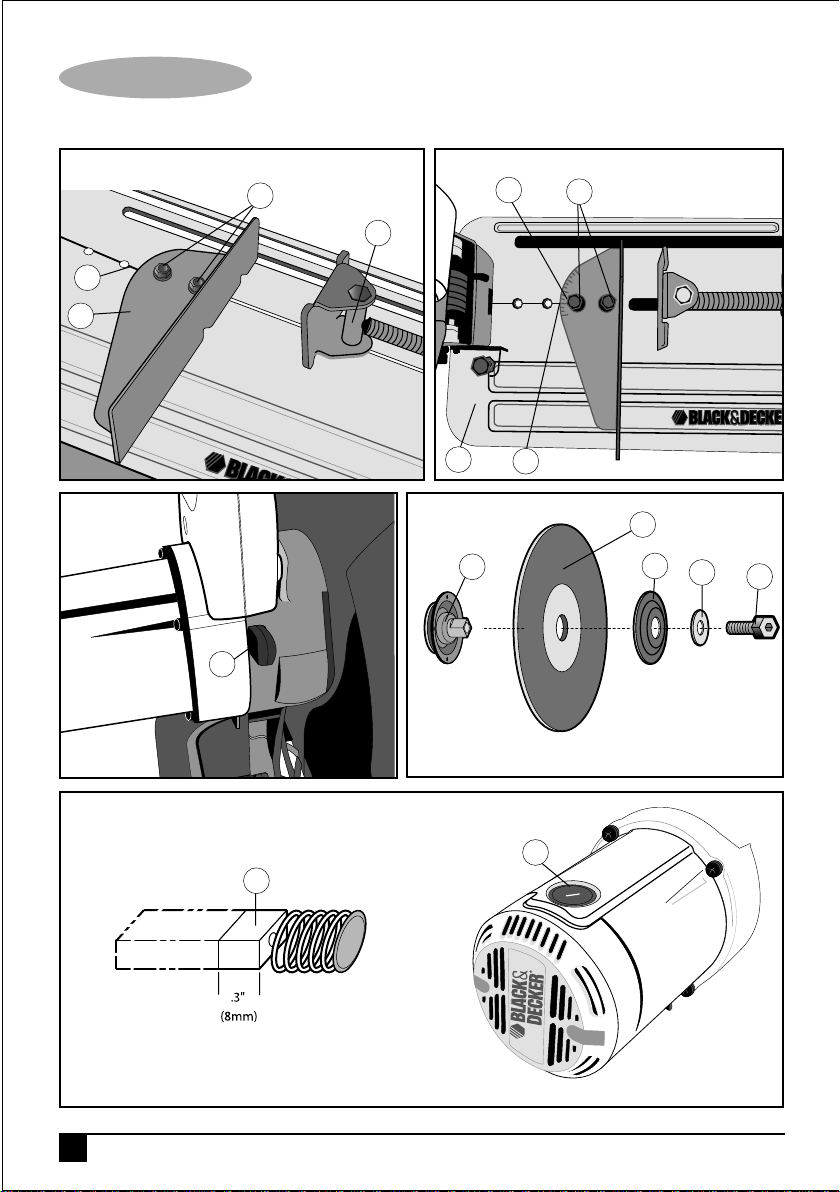
Removing and fitting a cutting
disc (fig. 7 - fig 8)
• Push in the spindle lock (L).
• Rotate the cutting disc (J) until it locks.
• Using the flat wrench (G), remove the bolt (S)
by turning counterclockwise and then remove
the washer (T) and the retaining flange (U).
• Check that the spacer (R) is in place against
the flange.
• Replace the cutting disc (J). Make sure that
the new disc is placed onto the spacer (R) in
the correct rotational direction.
• Secure the blade with the retaining flange (U),
the washer (T) and the bolt (S).
F. Vice
G. Flat Wrench
H. Crank
I. Vice Lever
J. Cutting disc
K. Guard
• Push in the spindle lock (L).
• Rotate the cutting disc (J) until it locks.
• Using the flat wrench (G), tighten the bolt (S)
by turning clockwise.
• Move the guard back down and release the
spindle lock (L).
• Adjust the cutting depth as necessary.
9

ENGLISH
Adjusting the cutting depth
(fig. 1)
The cutting depth can be adjusted to meet the
wear of the cutting disc.
• Make a dry run with the tool switched off and
check for clearance.
• If adjustment is required, proceed as follows:
• Loosen the lock nut (M) a few turns.
• Turn the depth stop bolt (M) in or out as to
achieve the required cutting depth.
• Tighten the lock nut (M).
Warning: Always adjust the depth stop to its
original position when replacing the cutting disc.
Clamping the workpiece in
position (fig. 2 - fig 4)
The tool is equipped with a vise (F)
• Pull the lever (I) toward the handle (H).
• Push the vise (F) forward until the jaw is
almost touching the workpiece.
• Press the lever (I) toward the jaw until it
engages with the clamp shaft.
• Rotate the handle (H) clockwise and clamp
the workpiece securely.
• To release the workpiece, rotate the handle
(H)counterclockwise.
• To increase the cutting capacity, place a
spacer block under the workpiece. The
spacer block should be slightly narrower than
the workpiece.
Warning: Support long workpieces using a
piece of wood. Do not clamp the cut off end.
Quick travel feature (fig. 4)
The clamp has a quick travel feature.
• To release the clamp, rotate the handle (H)
one or two turns counterclockwise and pull
the lever (I) toward the handle (H).
Setting the clamping position
(fig. 5)
The clamping position can be set to match the
cutting disc.
• Remove the fence bolts (P) using the flat
wrench (G).
• Move the fence (E) as required.
• Re-fit the fence bolts (P) and tighten them to
lock the fence (E).
Adjusting the angle of cut (fig. 6)
The tool can be used for mitre cuts up to 45°.
• Loosen the fence bolts (P) to release the
fence (E).
• Set the fence (E) to the required angle. The
angle can be read on the scale (Q).
• Tighten the fence bolts (P) to lock the fence
(E).
Checking and adjusting the
mitre scale (fig. 6)
• Loosen the fence bolts (P) to release the
fence (E).
• Pull down the arm and lock it in this position
by attaching the lock chain (A).
• Place a square against the fence (E) and the
left side of the cutting disc creating a perfect
90°. Check that the 0° marking on the scale
(Q) aligns with the marking on the base (D).
10

ENGLISH
• Tighten the fence bolts (P) to lock the fence
(E).
• Remove the lock chain (A) and return the
arm to its upper rest position.
Adjusting the spark deflector
(fig. 1)
• Loosen the screw (B).
• Set the spark deflector (C) as appropriate.
• Tighten the screw (B).
Use
Warning: Always observe the safety instructions
and applicable regulations.
Warning: Do not apply excessive pressure to
the tool.
Warning: Avoid overloading. Should the tool
become hot, let it run a few minutes under no
load condition.
Cutting capacity
The wide vise opening and high pivot point
provide cutting capacity for many large pieces.
Use the cutting capacity chart to determine total
maximum size of cuts that can be made with a
new wheel.
Caution: Certain large, circular or irregularly
shaped objects may require additional holding
means if they cannot be held securely in vise.
Maximum cutting capacity
Note: Capacity shown on chart assumes no
wheel wear and optimum fence position.
Workpiece
shape
90º Cutting A = 4-7/8" A = 4-1/2" 4-1/2" x 5-1/8" A = 4-1/2" x 5-3/8"
Angle (125mm) (115mm) (115mm x 130mm) (115mm x 137mm)
4" x 7-5/8"
(115mm x 130mm)
3" x 7-3/8"
(115mm x 130mm)
45º Cutting A= 4-1/2" A = 3-13/16" 4-1/2" x 3-13/16" A = 3-13/16"
Angle (115mm) (98mm) 4-1/8" x 3-3/4" 3-3/4"
(105mm x 95mm) (95mm)
Prior to operation:
• Install the appropriate cutting disc. Do not
use excessively worn discs. The maximum
rotation speed of the tool must not exceed
that of the cutting disc.
• Make sure the disc rotates in the direction of
the arrows on the accessory and the tool.
• Secure the workpiece.
• Always set the spark deflector correctly.
Switching on and off (fig. 1)
The on/off trigger switch (N) is mounted in the
operating handle.
• To run the tool, press the on/off trigger switch
(N).
• Keep the on/off switch depressed while
performing the operation.
• To stop the tool, release the trigger switch
(N).
Warning: Do not switch the tool on or off when
under load.
Warning: To prevent unauthorized use of tool,
install a standard padlock (not included) into the
padlock hole (O) located in the trigger switch.
Warning! Do not cut magnesium.
11

ENGLISH
Consult your dealer for further information
on the appropriate accessories.
Performing a cut (fig. 1)
• Place the material to be cut against the fence
(E) and secure using the vise (F).
• Switch on the tool and pull down the handle
to cut the workpiece. Allow the motor to
reach full speed before cutting.
• Allow the disc to cut freely. Do not force.
• After completing the cut, switch off the tool
and return the arm to its upper rest position.
Transporting (fig. 1)
The tool is equipped with a lock chain (A) which
locks the tool in closed-down position for
carrying.
Warning: Ensure that the tool is switched off
and disconnected from the mains supply before
transporting.
• Lower the guard (K) onto the cutting table
base (D) and secure the tool in this position
by securing the chain on the hook in the
handle.
• Transport the tool using the carrying handles.
• To release the tool, depress the operating
handle slightly and pull off the lock chain (A).
Maintenance
Your Black & Decker corded/cordless
appliance/tool has been designed to operate
over a long period of time with a minimum of
maintenance. Continuous satisfactory operation
depends upon proper appliance/tool care and
regular cleaning.
Warning! Before performing any maintenance
on corded/cordless appliance/tool:
• Switch off and remove the battery from the
appliance.
• Keep the ventilation slots clear and regularly
clean the housing with a soft cloth.
• Do not use abrasive cleaners.
Mains Plug Replacement
If a new mains plug needs to be fitted:
• Safely dispose of the old plug.
• Connect the brown lead to the live terminal of
the new plug.
• Connect the blue lead to the neutral terminal.
• If the product is class l (earthed), connect the
green / yellow lead to the earth terminal.
Warning! If your product is class ll double
insulated (only 2 wires in the cord set), no
connection is to be made to the earth terminal.
Follow the fitting instructions supplied with good
quality plugs.
Any replacement fuse must be of the same rating
as the original fuse supplied with the product.
Motor brush inspection and
replacement (fig. 9)
Warning! Turn off and unplug the tool. Be sure
the trigger switch is in the OFF position.
Brushes should be regularly inspected for wear.
To inspect brushes, remove brush cap (W).
Brushes (V) should slide freely in brush box. If
brushes are worn down to .3" (8mm) as shown in
Figure 9 they should be replaced.
To reinstall, push new brush back into brush box.
If replacing existing brush, maintain same
orientation as when removed. Replace the brush
cap (do not overtighten).
12

ENGLISH
Cleaning
Blowing dust and grit out of the main housing by
means of an air hose is recommended and may
be done as often as dirt is seen collecting in and
around the air vents. Always wear proper eye
and respiratory protection.
Repairs
To assure product SAFETY and RELIABILITY,
repairs, maintenance and adjustment should be
performed by authorized service centers or
other qualified service organizations, always
using identical replacement parts.
Lubrication
Closed-type, grease-sealed ball bearings are
used throughout. These bearings have sufficient
lubrication packed in them at the factory to last
the life of the chop saw.
Accessories
Caution! The use of any other accessory not
recommended for use with this tool could be
hazardous.
Max. Peripheral Speed m/s 80
Cutting Disc
Max. Disc Diameter mm 355
Disc Bore mm 25.4
Max Disc Thickness mm 3
Type Of Cutting Disc Straight, non recessed
Cross Cutting Capacity at 90º
Circular mm 125
Square mm 115
Rectangular mm 115 x 130
Angular mm 137 x 137
Cross Cutting Capacity at 45º
Circular mm 115
Square mm 98 x 98
Rectangular mm 105 x 95
Angular mm 95 x 95
Weight kg 18
Use only high-strength Type 1 organic bonded
wheels rated 4300 rpm or higher that comply
with EN12413.
Recommended accessories for use with your
tool are available at extra cost from your local
dealer or authorized service center.
Technical Data
CS355
(Type1)
Voltage V
Power Input W 2,300
No-Load Speed min
AC 220-240
-1
3,800
13

ENGLISH
Protecting the environment
Separate collection. This product must not
be disposed of with normal household
waste.
Should you find one day that your Black &
Decker product needs replacement, or if it is of
no further use to you, do not dispose of it with
other household waste. Make this product
available for separate collection.
• Black & Decker provides a facility for
recycling Black & Decker products once they
have reached the end of their working life.
This service is provided free of charge. To
take advantage of this service please return
your product to any authorised repair agent
who will collect them on our behalf.
• You can check the location of your nearest
authorised repair agent by contacting your
local Black & Decker office at the address
indicated in this manual. Alternatively, a list of
authorized Black & Decker repair agents and
full details of our after-sales service and
contact are available on the Internet at:
www.2helpU.com.
Warranty
If a Black & Decker product becomes defective
due to a material or manufacturing defect , within
12 months from the date of purchase, Black &
Decker guarantees to replace defective parts or
replace such products to ensure minimum
inconvenience to the customer unless:
• The product has been subjected to misuse or
neglect.
• The product has sustained damage through
foreign objects, substances or accidents.
• Repairs have been attempted by persons
other than authorised repair agents or Black
& Decker service staff.
To claim on the warranty, you will need to submit
proof of purchase to the seller or an authorised
repair agent. You can check the location of your
nearest authorised repair agent by contacting
your local Black & Decker office at the address
indicated in this manual. Alternatively, a list of
authorised Black & Decker repair agents and full
details of our after-sales service and contacts are
available on the Internet at: www.2helpU.com.
Please visit our website www.blackanddecker.ae
to register your new Black & Decker product and
to be kept up to date on new products and
special offers. Further information on the Black &
Decker brand and our range of products is
available at www.blackanddecker.ae.
14

ARABIC
N
M
G
E
D
L
K
J
H
F
I
A
G
15

ARABIC
O
N
M
C
B
G
E
D
L
F
Fig. 2
E
K
J
G
Fig. 1
H
I
Fig. 3
A
16
F
E
F
I
Fig. 4
H

ARABIC
Fig. 5
Q
E
Fig. 7
P
F
L
E
D
R
P
Q
J
U
Fig. 8
T
S
Fig. 6
Fig. 9
W
V
17

ARABIC
áeÓ°ùdG Ú°ù– øµÁ ,(∂dP ¤EG Éeh ¿OÉ©ŸG áWGôN
QÉ«àdG øe ájÉbh RÉ¡L ΩGóîà°SG ≥jôW øY á«FÉHô¡µdG
.á«°SÉ°ù◊G ‹ÉY ÒÑeCG »∏∏e 30 »≤ÑàŸG
øjôNB’G ¢UÉî°TC’G OÉ©HEG .4
‘ ÚcQÉ°ûŸG ÒZ ` ∫ÉØWC’G á°UÉN ` ¢UÉî°TCÓd íª°ùJ ’
ºgOÉ©HEG »¨Ñæjh π«°UƒàdG ∂∏°S hCG RÉ¡÷G á°ùeÓà πª©dG
.πª©dG á≤£æe øY
áeóîà°ùŸG ÒZ Iõ¡LC’G øjõîJ .5
Iõ¡LC’G øjõîJ Öéj ,áeóîà°ùe ÒZ ¿ƒµJ ÉeóæY
øY Gkó«©H ΩɵMEÉH ≥∏¨eh ±ÉL ¿Éµe ‘ á«FÉHô¡µdG
.∫ÉØWC’G ∫hÉæàe
Iƒ≤dÉH RÉ¡÷G πªY ∫ó©e IOÉjR ádhÉfi ÖæŒ .6
π°†aCG πµ°ûH πª©dG AGOCÉH »FÉHô¡µdG RÉ¡÷G Ωƒ≤j ±ƒ°S
.¬∏LCG øe √OGóYEG ” …òdG ∫ó©ŸÉH É
í«ë°üdG RÉ¡÷G ΩGóîà°SG .7
¬H Ωƒ≤J …òdG πª©dG AGOC’ IÒ¨°üdG Iõ¡LC’G Ωóîà°ùJ ’
á°ü°üfl ÒZ ¢VGôZC’ Iõ¡LC’G Ωóîà°ùJ ’ .á∏«≤ãdG Iõ¡LC’G
™£≤d ájôFGódG Ò°TÉæŸG Ωóîà°ùJ ’ ∫ÉãŸG π«Ñ°S ≈∏©a ;É¡d
.ôé°ûdG ófR hCG ¿É°üZCG
fÉeCG ÌcCGh
k
ΩGóîà°S’G ¢VôZ
Ö∏°üdG OGƒe ™«£≤àd ºª°üe ôµjO ófBG ∑ÓH ™«£≤àdG QÉ°ûæe
∂∏¡à°ùŸG ΩGóîà°S’ ºª°üe èàæŸG Gòg .∫ɵ°TC’G áØ∏àfl
.§≤a
áeÓ°ùdG äGOÉ°TQEG
á«FÉHô¡µdG Iõ¡LC’G áeÓ°S ¢Uƒ°üîH áeÉ©dG äÉ¡«ÑæàdG
,á«FÉHô¡µdG Iõ¡LC’G ΩGóîà°SG óæY !¬«ÑæJ
‘ á≤Ñ£ŸG áeÓ°ùdG óYGƒb ´ÉÑJG ÉkªFGO »¨Ñæj
á«FÉHô¡c áeó°Uh ≥jôM çhóM ô£N π«∏≤àd ∂àdhO
.á«°üî°T áHÉ°UEGh
ΩGóîà°SG πÑb ájÉæ©H
ÖÑ°ùàj ób .π«dódG Gòg ‘ í°Vƒe Oƒ°ü≤ŸG ΩGóîà°S’G
Gò¡H á«∏ªY ájCG ò«ØæJ hCG á≤ë∏e IóMh …CG ΩGóîà°SG
äGOÉ°TQE’G π«dO ‘ É¡H ≈°UƒŸG ∂∏J ±ÓîH RÉ¡÷G
äGOÉ°TQE’Gh äÉ¡«ÑæàdG áaɵH ®ÉØàM’G ≈Lôj
ÓeÉc π«dódG Gòg IAGôb »¨Ñj
k
.RÉ¡÷G
.á«°üî°T áHÉ°UEG çhóM ‘ Gòg
.kÓÑ≤à°ùe É¡«dEG ´ƒLô∏d
πª©dG á≤£æe áaɶf ≈∏Y ®ÉØ◊G .1
•
•
•
áÑ°SÉæŸG ¢ùHÓŸG AGóJQG .8
ób É¡fCG å«M ,äGôgƒéŸG hCG á°VÉØ°†ØdG ¢ùHÓŸG …óJôJ ’
®ÉØë∏d »bGh ô©°T AÉ£Z …óJQG .ácôëàŸG AGõLC’ÉH ≥∏©àJ
AGƒ¡dG ‘ πª©dG óæY .RÉ¡÷G øY Gkó«©H πjƒ£dG ô©°ûdG ≈∏Y
≥∏Mõà∏d á©fÉe ájòM
áeɪc hCG ´Éæb Ωóîà°SG .á«bGƒdG äGQɶædG ÉkehO Ωóîà°SG
øe IôjÉ£àe äɪ«°ùL hCG áHôJCG óYÉ°üJ ∫ɪàMG óæY áHôJCG
äɪ«°ù÷G ∂∏J ¿ƒµJ ¿CG πªàëŸG øe ¿Éc GPEG .äÉ«∏ª©dG
.IQGô◊G øe »bGh QõÄe Ék°†jCG …óJQG ,ÒÑc óM ¤EG áæNÉ°S
áeÓ°S IPƒN …óJQG .äÉbhC’G áaÉc ‘ ¿PC’G »bGh …óJQG
18
CGh äGRÉØb AGóJQG π°†Øj ,≥∏£dG
.áÑ°SÉæe
á«bGƒdG äGó©ŸG ΩGóîà°SG .9
.äÉbhC’G áaÉc ‘
´ƒbh ‘ óYÉ≤ŸGh ΩÉcôdÉH á¶àµŸG ≥WÉæŸG ÖÑ°ùàJ ób
çOGƒM
πª©dG á≤£æe áÄ«H IÉYGôe .2
AGƒLC’G ‘ RÉ¡÷G Ωóîà°ùJ ’ .ô£ª∏d RÉ¡÷G ¢Vô©J ’
Gkó«L IAÉ°†e πª©dG á≤£æe ≈∏Y ®ÉØ◊G »¨Ñj .áÑWôdG
¿ƒµj ÉeóæY RÉ¡÷G Ωóîà°ùJ ’ .(¢ùcƒd 300 ` 250)
OƒLh ádÉM ‘
Ö«HÉfC’G πãe) á°VQDƒŸG í£°SCÓd º°ù÷G á°ùeÓe ÖæŒ
RÉ¡÷G ΩGóîà°SG óæY .(äÉLÓãdGh óbGƒŸGh ICÉaóŸG Iõ¡LCGh
èàæJ ÉeóæYh á©ØJôŸG áHƒWôdG πãe) á«°SÉb ±hôX â–
Óãe ;QÉéØfG hCG ≥jôM çhóM ô£N ∑Éæg
k
.äGRÉZh ∫É©à°TÓd á∏HÉb πFGƒ°S
á«FÉHô¡c áeó°U çhóM øe ¢SGÎM’G .3

ARABIC
Oƒ°ü≤ŸG ÒZ 𫨰ûàdG AóH ™æe .17
¿CG ócCÉJ .ìÉàØŸG ≈∏Y áYƒ°Vƒe ∂©HÉ°UC
Gh RÉ¡÷G πª– ’
.»FÉHô¡µdG QÉ«àdÉH π«°UƒàdG πÑb ≥∏¨e RÉ¡÷G
‘ ΩGóîà°SÓd áÑ°SÉæe π«°UƒJ äÓHÉc ΩGóîà°SG .18
≥∏£dG AGƒ¡dG
” GPEG ¬dóÑà°SGh π«°UƒàdG πHÉc ¢üëaG ,ΩGóîà°S’G πÑb
,≥∏£dG AGƒ¡dG ‘ RÉ¡÷G ΩGóîà°SG óæY .∞∏J …CG ≈∏Y Qƒã©dG
‘ ΩGóîà°S’G πLCG øe Ió©e π«°UƒJ äÓHÉc §≤a Ωóîà°SG
.∂dòd kÉ≤ah IOófih ≥∏£dG AGƒ¡dG
Ék¶≤j øc .19
Ωóîà°ùJ ’h º«∏°ùdG ¢ù◊G Ωóîà°SGh ¬∏©ØH Ωƒ≤J Ée ÖbGQ
.Ékµ¡æe ¿ƒµJ ÉeóæY RÉ¡÷G
áØdÉàdG AGõLC’G ≈∏Y ±ô©à∏d RÉ¡÷G ¢üëa .20
ájÉæ©H π«°UƒàdG πHÉch RÉ¡÷G ¢üëaG ,ΩGóîà°S’G πÑb
≈∏Y ±ô©à∏d RÉ¡÷G ¢üëaG .áØdÉàdG AGõLC’G ≈∏Y ±ô©à∏d
AGõLC’G ≈∏Y ±ô©à∏dh ácôëàŸG AGõLC’G ∞∏Jh IGPÉfi Aƒ°S
ób iôNCG ´É°VhCG ájCGh í«JÉØŸGh äÉ«bGƒdG ∞∏Jh IQƒ°ùµŸG
±ƒ°S RÉ¡÷G ¿CG øe ócCÉJ .RÉ¡÷G 𫨰ûJ IAÉØc ≈∏Y ôKDƒJ
.É¡∏LCG øe ´ƒæ°üŸG ᪡ŸG òØæ«°Sh Ö°SÉæŸG πµ°ûdÉH πª©j
hCG áØdÉJ AGõLCG ájCG Qƒã©dG ádÉM ‘ RÉ¡÷G Ωóîà°ùJ ’h
¬∏«¨°ûàH ìÉàØŸG º≤j ⁄ GPEG RÉ¡÷G Ωóîà°ùJ ’ ,∂dòc .áÑ«©e
hCG áØdÉJ AGõLCG ájCG ≈∏Y Qƒã©dG ” GPEGh .¬∏«¨°ûJ ±É≤jEGh
ôµjO ófBG ∑ÓH áfÉ«°U π«ch ᣰSGƒH É¡dGóÑà°SÉH ºb áÑ«©e
.∂°ùØæH áfÉ«°U ájCG AGôLEG Ék≤∏£e ∫hÉ– ’ .óªà©e
!¬«ÑæJ .21
Gò¡H á«∏ªY ájCG ò«ØæJ hCG á≤ë∏e IóMh …CG ΩGóîà°SG ÖÑ°ùàj ób
‘ Gòg äGOÉ°TQE’G π«dO ‘ É¡H ≈°UƒŸG ∂∏J ±ÓîH RÉ¡÷G
.á«°üî°T áHÉ°UEG çhóM
πgDƒe ¢üî°T ᣰSGƒH RÉ¡÷G ìÓ°UEG »¨Ñæj .22
»¨Ñæj .á∏°üdG äGP áeÓ°ùdG íFGƒ∏d Ék≤ah ºª°üe RÉ¡÷G Gòg
.óªà©e ôµjO ófBG ∑ÓH áfÉ«°U π«ch ᣰSGƒH RÉ¡÷G ìÓ°UEG
¢UÉî°TCG ᣰSGƒH §≤a ìÓ°UE’G äÉ«∏ªY AGôLEG Ωõ∏jh
∂dP ±ÓN A»°T …CG ;á«∏°UCG QÉ«Z ™£b ΩGóîà°SÉH Ú∏gDƒe
.Ωóîà°ùª∏d ≠dÉH ô£N çhóM ‘ ÖÑ°ùàj ób
QÉѨdG êGôîà°SG ádBG π«°UƒJ .10
êGôîà°SG ≥aGôe π«°Uƒàd Iôaƒe Iõ¡LCG ∑Éæg âfÉc GPEG
É¡eGóîà°SGh Iõ¡LC’G ∂∏J π«°UƒJ øe ócCÉJ ,™ª÷Gh QÉѨdG
.Ö°SÉæŸG πµ°ûdÉH
»FÉHô¡µdG QÉ«àdG ∂∏°S ∫ɪ©à°SG IAÉ°SEG ΩóY .11
»FÉHô¡µdG QÉ«àdG ∂∏°S ∫ÓN øe Ék`≤∏£e RÉ¡÷G πª– ’
¬∏°üØd Ék`≤∏£e »FÉHô¡µdG QÉ«àdG ∂∏°S Öë°ùJ ’ .¬H ¢UÉÿG
Gkó«©H »FÉHô¡µdG QÉ«àdG ∂∏°ùH ®ÉØàM’G »¨Ñæj .¢ùÑ≤ŸG øY
.IOÉ◊G ±Gƒ◊G hCG âjõdG hCG IQGô◊G øY
πª©dG á©£b â«ÑãJ .12
ÌcCG É¡fEG ;πª©dG á©£b ∂°ùŸ áeõ∏e …CG hCG ∂HÉ°ûŸG Ωóîà°SG
.IGOC’G 𫨰ûàd øjó«dG Éà∏c Qô–h É
fÉeCG
k
•ôØŸG ÜGÎb’G ΩóY .13
‘ Ö°SÉæŸG ¿RGƒàdGh Úeó≤dG äÉÑK ≈∏Y ®ÉØ◊G »¨Ñæj
.äÉbhC’G áaÉc
ájÉæ©H Iõ¡LC’G ≈∏Y ®ÉØ◊G .14
áØ«¶fh IOÉM ádÉM ‘ ™«£≤àdG äGhOCG ≈∏Y ®ÉØ◊G »¨Ñæj
º«ë°ûàdG äGOÉ°TQEG ™ÑJG .É
fÉeCG ÌcCGh π°†aCG AGOCG πLCG øe
k
‘h ,ÉkjQhO RÉ¡÷G ∑Ó°SCG ¢üëØH ºb .äÉ≤ë∏ŸG Ò«¨Jh
≥aôe ᣰSGƒH É¡MÓ°UEG »¨Ñæj ∞∏J …CG ≈∏Y Qƒã©dG ádÉM
ÉkjQhO π«°UƒàdG ∑Ó°SCG ¢üëØH ºb .óªà©e áfÉ«°U
®ÉØ◊G »¨Ñæj .∞∏J …CG ≈∏Y Qƒã©dG ádÉM ‘ É¡dóÑà°SGh
âjõdG øe á«dÉNh áØ«¶fh áaÉL ádÉM ‘ Ú°†Ñ≤ŸG ≈∏Y
.ºë°ûdGh
RÉ¡÷G π°üa .15
πÑb ÉkeÉ“ RÉ¡÷G ∞bƒàj ≈àM ô¶àfGh RÉ¡÷G ±É≤jEÉH ºb
QÉ«àdG Qó°üe øY RÉ¡÷G π°üaG .ájÉYQ ¿hO ¬côJ
™£b ájCG Ò«¨J πÑbh Ωóîà°ùe ÒZ ¿ƒµj ÉeóæY »FÉHô¡µdG
.áfÉ«°üdG πÑbh äÉ≤ë∏e hCG QÉ«Z
ájõ«∏‚E’G í«JÉØŸGh ájOÉ©dG í«JÉØŸG ádGREG .16
…õ«∏‚EG ìÉàØe hCG …OÉY ìÉàØe …CG ádGREG øe ÉkehO ócCÉJ
.RÉ¡÷G 𫨰ûJ πÑb RÉ¡÷G øe
19

ARABIC
ºàj »àdG IOÉŸÉHh íFGöûdG ™«£≤àH ájGQO ≈∏Y øc
AGõLC’G ∑ôJG .áæNÉ°Sh IOÉM ¿ƒµJ ób .É¡©«£≤J
.É¡µ°ùe πÑb OÈJ áYƒ£≤ŸG
ÖæŒ .ΩGóîà°S’G AÉæKCG É
.𫨰ûàdG ó©H QƒØdG ≈∏Y QöûdG ¢ùcÉY πjó©J hCG á°ùeÓe
™«£≤àdG ¢Uôb ∞bƒàj ≈àM ô¶àfGh RÉ¡÷G ±É≤jEÉH ºb
.äGOGóYE’G Ò«¨J hCG πª©dG á©£b ∂jô– πÑb
¢Uôb ±É≤jEG Ék≤∏£e ∫hÉ– ’ ,RÉ¡÷G ±É≤jEG ó©H
.¢Uô≤dG ÖfÉL ≈∏Y §¨°†dG ≥jôW øY ™«£≤àdG
¤EG πFGƒ°ùdG ∂∏J …ODƒJ ób .™«£≤àdG πFGƒ°S Ωóîà°ùJ ’
.á«FÉHô¡c áeó°U çhóM hCG ≥jôM ∫É©°TEG
πµ°ûH áeƒYóeh áàÑãe πª©dG á©£b ¿CG øe ócCÉJ
ácöûdG πÑpb øe É¡H ≈°UƒŸG ™«£≤àdG ¢UGôbCG Ωóîà°SG
QÉ°ûæŸG äGôØ°T Ék≤∏£e Ωóîà°ùJ ’ .§≤a á©æ°üŸG
.áææ°ùŸG äGôØ°ûdG øe ôNCG ´ƒf …CG hCG ájôFGódG
¢Uô≤d É¡H 샪°ùe áYöS ≈°übCG ¿ƒµJ ¿CG Ωõ∏j
¿hO RÉ¡÷G áYöS øe ÈcCG hCG …hÉ°ùJ ÉkªFGO ™«£≤àdG
OÉ©HC’G ™e ≥aGƒàJ ’ »àdG ™«£≤àdG ¢UGôbCG Ωóîà°ùJ ’
QÉ«©ŸG ™e ≥aGƒàJ »àdG ™«£≤àdG ¢UGôbCG §≤a Ωóîà°SG
πÑb í«ë°U πµ°ûH ™«£≤àdG ¢Uôb Ö«côJ øe ócCÉJ
30 IóŸ øeBG ™°Vh ‘ πªpM ¿hO πª©j RÉ¡÷G ∑ôJG
çóM GPEG hCG ÒÑc RGõàgG ∑Éæg ¿Éc GPEG .πbC’G ≈∏Y á«fÉK
πLCG øe ¬°üëaGh RÉ¡÷G ±É≤jEÉH ºb ,ôNBG Ö«Y …CG
.É¡ÑfGƒL ≈∏Y òë°û∏d ™«£≤àdG ¢UGôbCG Ωóîà°ùJ ’
hCG •ÓÑdG hCG ܃£dG hCG áfÉ°SôÿG OGƒe ™«£≤àH º≤J ’ •
æNÉ°S QöûdG ¢ùcÉY íÑ°üj
k
.Ö°SÉæe
.áMƒ∏dG ≈∏Y IOóëŸG 𫪖
.á«æØdG äÉfÉ«ÑdG ‘ IOQGƒdG
.EN12413
.ΩGóîà°S’G
.ÖÑ°ùdG ójó–
.∂«eGÒ°ùdG
•
Ò°TÉæe ¢Uƒ°üîH á«aÉ°VEG áeÓ°S äGOÉ°TQEG
Gòg 𫨰ûJ AÉæKCG áªFÓŸG πª©dG äGRÉØb ÉkªFGO …óJQG •
•
’ .™«£≤àdG ¢Uôb øY Gkó«©H …ójC’G ≈∏Y ®ÉØ◊G »¨Ñæj
•
…hój AGôLEG Ö∏£àJ »àdG πª©dG ™£b ™«£≤àH GkóHCG º≤J
15 øY π≤J áaÉ°ùà QGhódG ™«£≤àdG ¢Uôb øe Üô≤dÉH
•
1.2 øY É¡µª°S π≤j »àdG πª©dG ™£b ™«£≤àH º≤J ’
•
Gòg ™e ôaƒŸG ™«£≤àdG ¢Uôb ΩGóîà°SG óæY º∏e
•
‘ äÉ«bGƒdG OƒLh ¿hO RÉ¡÷G Gòg 𫨰ûàH º≤J ’
.ɡfɵe
•
.πª©dG á©£b â«ÑãJ ¿hO á«∏ªY ájCG ò«ØæàH º≤J ’
.ΩɵMEÉH πª©dG á©£b â«Ñãàd »°SÉ°SC’G ∂Ñ°ûŸG Ωóîà°SG
•
âÑãe ô≤à°ùeh …ƒà°ùe í£°S ≈∏Y ÉkehO RÉ¡÷G ™°V •
™£≤dGh ≥FÉbôdG πãe ,áÑFÉ°ùdG OGƒŸG øe ‹ÉNh Gkó«L
•
≈∏Y ±ô©à∏d ™«£≤àdG ¢Uôb ¢üëaG ,ΩGóîà°S’G πÑb
•
‘ ™«£≤àdG ¢Uôb øe ¢ü∏îJ .܃«©dG hCG ¥ƒ≤°ûdG
.™«£≤àdG ¢Uôb ∞∏N ∑ój ó“ ’
.IÒ¨°üdG
.Ö«Y hCG ≥°T OƒLh øe ócCÉàdG ádÉM
•
πª©dG á©£≤d ™«£≤àdG ¢Uôb á°ùeÓe ΩóY øe ócCÉJ
•
πeÉ©àdG hCG ™«£≤àdG ¢Uôb OGóJQG ÖæŒ ,𫨰ûàdG AÉæKCG
RÉ¡÷G 𫨰ûJ ±É≤jEÉH ºb ,∂dP çóM GPEG .áfƒ°ûîH ¬©e
•
¢Uôb IGPÉëà ±ƒbƒdG AÉæKCG RÉ¡÷G 𫨰ûàH º≤J ’
á≤£æe øY øjôNB’G ¢UÉî°TC’G OÉ©HEG »¨Ñæj .™«£≤àdG
.RÉ¡÷G 𫨰ûJ πÑb
.™«£≤àdG ¢Uôb ¢üëaGh
™«£≤àdG
.RÉ¡÷G
•
.º°S
•
.RÉ¡÷G
•
•
•
•
•
•
•
.πª©dG
20

ARABIC
É¡©«£≤J ܃∏£ŸG IOÉŸG
™«£≤àdG ¢Uôb ´ƒf •
ájò¨àdG Iƒb •
.™ª°ùdG ájÉbƒd áÑ°SÉæŸG äGAGôLE’G òîJG !¬«ÑæJ •
á«≤ÑàŸG ôWÉîŸG
:ä’B’G √òg ΩGóîà°S’ áeRÓe ôWÉfl »g á«dÉàdG ôWÉîŸG
.IQGhO AGõLCG ájCG á°ùeÓe øY áŒÉædG äÉHÉ°UE’G
.™«£≤àdG ¢Uôb ¥õ“ øY áŒÉædG äÉHÉ°UE’G •
ÉkMƒ°Vh ÌcC’G ôWÉîŸG »g ôWÉîŸG √òg
.𫨰ûàdG ¥É£f ‘
.IQGhódG ádB’G AGõLCG ¥É£f ‘ •
ΩGóîà°SGh á∏°üdG äGP áeÓ°ùdG íFGƒd ≥«Ñ£J øe ºZôdG ≈∏Y
.á«≤ÑàŸG ôWÉîŸG ¢†©H ÖæŒ øµÁ ’ ,áeÓ°ùdG Iõ¡LCG
:»∏j Ée á«≤ÑàŸG ôWÉîŸG √òg πª°ûJ
.™ª°ùdG ∞©°V
øe IÉ£¨ŸG ÒZ AGõLC’G øY áŒÉædG çOGƒ◊G ô£N •
.QGhódG ™«£≤àdG ¢Uôb
.¢Uô≤dG Ò«¨J óæY áHÉ°UE’G ô£N
.QÉ°ûæŸG äÉ«bGh íàa óæY ™HÉ°UC’G QÉ°ûëfG ô£N •
á«FÉHô¡µdG áeÓ°ùdG
’ ,∂dòd ;ÉkLhOõe k’õY ∫hõ©e RÉ¡÷G Gòg
øe ÉkªFGO ócCÉàdG »¨Ñæjh .»°VQCG ∂∏°S ¤EG áLÉM
áMƒd ≈∏Y í°VƒŸG ó¡÷G ™e »FÉHô¡µdG QÉ«àdG ó¡L ≥aGƒJ
¢ùHÉ≤H øMÉ°ûdG IóMh ∫GóÑà°SG Ék≤∏£e ∫hÉ– ’ .Úæ≤àdG
.º¶àæe »FÉHô¡c QÉ«J
øe ¬dGóÑà°SG Öéj ,»FÉHô¡µdG QÉ«àdG ∂∏°S ∞∏J ádÉM ‘
ôµjO ófBG ∑ÓH áfÉ«°U õcôe hCG á©æ°üŸG ácöûdG πÑpb
.ôWÉîŸG Öæéàd óªà©e
•
•
•
•
•
•
hCG ᫵«à°SÓÑdG hCG á«Ñ°ûÿG OGƒŸG ™«£≤àH º≤J ’ •
.á«YÉ棰U’G
.í«∏°ùàdG ójóM OGƒe ™«£≤àH º≤J ’
.Ωƒ«°ù«æ¨ŸG OGƒe ™«£≤àH º≤J ’ •
.»M »FÉHô¡c QÉ«J É¡H »àdG OGƒŸG ™«£≤àH º≤J ’ •
º≤J ’ .ájƒ¡àdG Ió«L á≤£æe ‘ RÉ¡÷G Gòg Ωóîà°SG •
∫É©à°TÓd á∏HÉ≤dG πFGƒ°ùdG øe Üô≤dÉH RÉ¡÷G 𫨰ûàH
íFGöûdG hCG äGQGöûdG …ODƒJ ób .áHôJC’G hCG äGRɨdG hCG
∑ôëŸG ¿GQhO hCG ™«£≤àdG á«∏ªY øe áŒÉædG áæNÉ°ùdG
.¥GÎMÓd á∏HÉ≤dG OGƒŸG ∫É©°TEG ¤EG
‘ πª©dG óæY ájƒ¡àdG äÉëàa …QhO πµ°ûH ∞¶f
äÉëàa ∞«¶æJ ΩRÓdG øe íÑ°UCG GPEG .áHÎe ±hôX
QÉ«àdG Qó°üe øY k’hCG RÉ¡÷G π°üa ôcòJ ,ájƒ¡àdG
.»FÉHô¡µdG
»ªfi ¿Éµe ‘ ™«£≤àdG ¢UGôbCG øjõîàH ÉkªFGO ºb
.∫ÉØWC’G ∫hÉæàe øY Gkó«©H ±ÉLh Gkó«L
πªfi QÉÑZ ódƒJ ¤EG RÉ¡÷G Gòg ΩGóîà°SG …ODƒj ób !¬«ÑæJ
äÉgƒ°ûàdG hCG ¿ÉWöùdG ÖÑ°ùJ É¡fCG ±hô©e ájhɪ«c OGƒÃ
»bGh Ωóîà°SG .á«HÉ‚E’G QGöVC’G øe ÉgÒZh hCG á«≤∏ÿG
.Ö°SÉæŸG ¢ùØæàdG
™e §≤a ™£≤dG QÉ°ûæe á∏éY Ωóîà°SG !¬«ÑæJ
√Qób ≈°übCG ô£bh º∏e 3 √Qób ≈°übCG ∂ª°S
.º∏e 355
±É≤jEG ó©H ¿GQhódG ‘ ™«£≤àdG á∏éY ôªà°ùJ ±ƒ°S !¬«ÑæJ
.RÉ¡÷G 𫨰ûJ
4300 É¡fCG ≈∏Y áææ≤e áªYóe äÓéY §≤a Ωóîà°SG
.≈∏YCG hCG á≤«bódG ‘ IQhO
QÉ°ûæŸG äÉ«bGh Ωóîà°SGh Ú©dG »bGh ÉkªFGO …óJQG
¢ùØæàdG »bGh Ωóîà°SGh ∂Ñ°ûà πª©dG á©£b ∂°ùeGh
.Ö°SÉæŸG
:AÉ°Vƒ°V çhóM ‘ IôKDƒe πeGƒY »g á«dÉàdG πeGƒ©dG
•
•
•
•
•
21

ARABIC
»bGƒdG .∑
¿GQhódG OƒªY πØb .∫
¥ÓZE’G ádƒª°Uh ≥ª©dG ójó– IóMh Qɪ°ùe .Ω
𫨰ûàdG ìÉàØe .¿
πØ≤dG áëàa .¢S
êÉ«°ùdG ÒeÉ°ùe .´
Ö«cÎdG
QÉ«àdG Qó°üe øY ¬∏°üaGh RÉ¡÷G 𫨰ûJ ±É≤jEÉH ºb !¬«ÑæJ
Ö«côJ hCG ádGREG hCG äÓjó©J ájCG AGôLEG πÑb »FÉHô¡µdG
¥ÓZE’G ™°Vh ‘ 𫨰ûàdG ìÉàØe ¿CG øe ócCÉJ .äÉ≤ë∏ŸG
.á∏é©dG ∑ô– AÉæKCG πjó©J …CG AGôLEÉH º≤J ’ .(OFF)
™«£≤J ¢Uôb Ö«côJh ádGREG
(8 πµ°ûdG – 7 πµ°ûdG)
.(∫) ¿GQhódG OƒªY πØb ≈∏Y §¨°VG •
‘ ¬à«ÑãJ ºàj ≈àM (…) ™«£≤àdG ¢Uôb IQGOEÉH ºb •
.¬©°Vƒe
ádGREÉH ºbh ,(R) í£°ùŸG …õ«∏‚E’G ìÉàØŸG Ωóîà°SG
ácôM √ÉŒG ¢ùµY ‘ ¬JQGOEG ≥jôW øY (¥) »ZÈdG
áØ°Th (Q) áµ∏ØdG ádGREÉH ºb ºK ;áYÉ°ùdG ÜQÉ≤Y
.(¢T) â«ÑãàdG
πHÉ≤e É¡fɵe ‘ IOƒLƒe (¢U) IóYÉÑŸG ¿CG øe ócCÉJ
.áØ°ûdG
¢Uô≤dG ™°Vh øe ócCÉJ .(…) ™«£≤àdG ¢Uôb ∫óÑà°SG
.í«ë°üdG ¿GQhódG √ÉŒG ‘ (¢U) IóYÉÑŸG ≈∏Y ójó÷G
(¢T) â«ÑãàdG áØ°T ΩGóîà°SÉH IôØ°ûdG â«ÑãJ ΩɵMEÉH ºb
.(¥) »ZÈdGh (Q) áµ∏ØdGh
.(∫) ¿GQhódG OƒªY πØb ≈∏Y §¨°VG
‘ ¬à«ÑãJ ºàj ≈àM (…) ™«£≤àdG ¢Uôb IQGOEÉH ºb •
.¬©°Vƒe
»ZÈdG §HQG ,(R) í£°ùŸG …õ«∏‚E’G ìÉàØŸG ΩGóîà°SÉH
.áYÉ°ùdG ÜQÉ≤Y ácôM √ÉŒG ‘ ¬JQGOEG ≥jôW øY (¥)
πØb QôMh »Ø∏ÿG √ÉŒ’G ‘ πØ°SCG ¤EG »bGƒdG ∑ôM
.(∫) ¿GQhódG OƒªY
.ΩRÓdG Ö°ùM ™«£≤àdG ≥ªY πjó©àH ºb
»FÉHô¡µdG ó¡÷G ¢VÉØîfG
ó¡÷G ‘ ¢VÉØîfG çhóM ‘ äGQÉ«àdG ≥aóJ ÖÑ°ùàj
.IÒ°üb IóŸ »FÉHô¡µdG
»FÉHô¡µdG QÉ«àdG ±hôX πX ‘ iôNC’G äGó©ŸG ôKCÉàJ ób
0.12 øe πbCG »FÉHô¡µdG QÉ«àdG áehÉ≤e Ωɶf âfÉc GPEG
.äÉHGô£°VG çhóM πªàëŸG ÒZ øe ¬fEÉa ,ΩhCG
¬«ÑæàdG RƒeQ
:RÉ¡÷G ≈∏Y á«dÉàdG RƒeôdG ≈∏Y Qƒã©dG ºàj
≈∏Y »¨Ñæj ,áHÉ°UE’G ô£N π«∏≤àd !¬«ÑæJ
.äGOÉ°TQE’G π«dO IAGôb Ωóîà°ùŸG
.á«bGƒdG äGQɶædG ÉkªFGO …óJQG
.™ª°ùdG »bGh ÉkªFGO …óJQG
•
.á«dÉàdG ÉjGõŸG áaÉc hCG ¢†©H ≈∏Y RÉ¡÷G Gòg πªà°ûj
≥∏Z á∏°ù∏°S .CG
•
QöûdG ¢ùcÉY »ZôH .Ü
•
•
•
•
•
•
QöûdG ¢ùcÉY .ê
í£°ùe …õ«∏‚EG ìÉàØe .R
áeõ∏ŸG ´GQP .•
™«£≤J ¢Uôb .…
.á«JGƒŸG ÒZ
ÉjGõŸG
IóYÉb .O
êÉ«°S .`g
áeõ∏e .h
∂fôc .ì
22

ARABIC
(4 πµ°ûdG) ™jöùdG ∑ôëàdG Iõ«e
.™jöùdG ∑ôëàdG Iõ«Ã ∂Ñ°ûŸG ™àªàj
‘ ÚàØd hCG áØd (ì) ¢†Ñ≤ŸG IQGOEÉH ºb ,∂Ñ°ûŸG ôjôëàd •
(•) ´GQòdG Öë°SGh áYÉ°ùdG ÜQÉ≤Y ácôM √ÉŒG ¢ùµY
.(ì) ¢†Ñ≤ŸG √ÉŒ
(5 πµ°ûdG) ∂Ñ°ûŸÉH â«ÑãàdG ™°Vƒe §Ñ°V
¢Uôb ™e ≥aGƒà∏d ∂Ñ°ûŸÉH â«ÑãàdG ™°Vƒe §Ñ°V øµÁ
.™«£≤àdG
ìÉàØŸG ΩGóîà°SÉH (´) êÉ«°ùdG ÒeÉ°ùe ádGREÉH ºb
.(R) í£°ùŸG …õ«∏‚E’G
.܃∏£ŸG Ö°ùM (`g) êÉ«°ùdG ∑ôM
≥∏¨d É¡£HQGh (´) êÉ«°ùdG ÒeÉ°ùe Ö«côJ IOÉYEÉH ºb •
.(`g) êÉ«°ùdG
(6 πµ°ûdG) ™£≤dG ájhGR πjó©J
π°üJ ájhGõH ™£≤dG äÉ«∏ªY πLCG øe RÉ¡÷G ΩGóîà°SG øµÁ
.áLQO 45 ¤EG
.(`g) êÉ«°ùdG ôjôëàd (´) êÉ«°ùdG ÒeÉ°ùe QôM
IAGôb øµÁ .áHƒ∏£ŸG ájhGõdG ≈∏Y (`g) êÉ«°ùdG §Ñ°VG •
.(±) êQóàdG ≈∏Y ájhGõdG
.(`g) êÉ«°ùdG ≥∏¨d (´) êÉ«°ùdG ÒeÉ°ùe §HQG
(6 πµ°ûdG) ájhGõdG êQóJ πjó©Jh ¢üëa
.(`g) êÉ«°ùdG ôjôëàd (´) êÉ«°ùdG ÒeÉ°ùe QôM •
∫ÓN øe ¬©°Vƒe ‘ ¬≤∏ZCGh πØ°SC’ ´GQòdG Öë°SG •
.(CG) ≥∏¨dG á∏°ù∏°S π«°UƒJ
øe öùjC’G ÖfÉ÷Gh (`g) êÉ«°ùdG πHÉ≤e QÉ‚ ájhGR ™°V
.§Ñ°†dÉH áLQO 90 ÉgQób ájhGR AÉ°ûfE’ ™«£≤àdG ¢Uôb
áeÓ©∏d ájPÉfi (±) êQóàdG ≈∏Y0° áeÓY ¿CG øe ócCÉJ
.(O) IóYÉ≤dG ≈∏Y IOƒLƒŸG
(1 πµ°ûdG) ™«£≤àdG ≥ªY πjó©J
¢Uôb πcBÉJ ™e Ö°SÉæàj »µd ™«£≤àdG ≥ªY πjó©J øµÁ
¢üëaGh ¬∏«¨°ûJ ±É≤jEG AÉæKCG RÉ¡÷ÉH áØd AGôLEÉH ºb •
.¢Uƒ∏N OƒLh ≈∏Y ±ô©à∏d
äGƒ£ÿG ™ÑJG ,πjó©J AGôLEG ܃∏£ŸG øe ¿Éc GPEG •
:á«dÉàdG
.á∏«∏b äGQhóH (Ω) ¥ÓZE’G ádƒª°U ∂a •
hCG πNGódG ¤EG (Ω) ≥ª©dG ójó– IóMh Qɪ°ùe IQGOEÉH ºb •
•
•
É¡©°Vh ≈∏Y ≥ª©dG ójó– IóMh πjó©àH ÉkªFGO ºb :¬«ÑæJ
.܃∏£ŸG ™«£≤àdG ≥ªY ≥«≤ëàd êQÉÿG
.(Ω) ¥ÓZE’G ádƒª°U §HQG •
.™«£≤àdG ¢Uôb ∫GóÑà°SG óæY »∏°UC’G
áeõ∏à πª©dG á©£b â«ÑãJ
(4 πµ°ûdG – 2 πµ°ûdG)
(h) áeõ∏à Ohõe RÉ¡÷G Gòg
•
á©£b ™e ∂ØdG ¢ùeÓàj ≈àM ΩÉeCÓd (h) áeõ∏ŸG ™aOG •
™e ≥°û©àj ≈àM ∂ØdG √ÉŒ (•) ´GQòdG ≈∏Y §¨°VG •
•
ÜQÉ≤Y ácôM √ÉŒG ‘ (ì) ¢†Ñ≤ŸG IQGOEÉH ºb •
¢ùµY ‘ (ì) ¢†Ñ≤ŸG IQGOEÉH ºb ,πª©dG á©£b ôjôëàd •
.πª©dG á©£b â– IóYÉÑe ™°V ,™«£≤àdG IQób IOÉjõd •
•
.πª©dG á©£b øe
á©£b ΩGóîà°SÉH á∏jƒ£dG πª©dG ™£b º«YóàH ºb :¬«ÑæJ
.(ì) ¢†Ñ≤ŸG √ÉŒ (•) ´GQòdG Öë°SG •
.∂Ñ°ûŸG ´òL
.ΩɵMEÉH πª©dG á©£b âÑKh áYÉ°ùdG
.áYÉ°ùdG ÜQÉ≤Y ácôM √ÉŒG
Ó«∏b ≥«°VCG IóYÉÑŸG ¿ƒµJ ¿CG »¨Ñæj
k
.áeõ∏à ™«£≤àdG ájÉ¡f âÑãJ ’ .Ö°ûN
.™«£≤àdG
.πª©dG
23

ARABIC
á©£b πµ°T
πª©dG
A = 4-1/2" x 5-3/8" 4-1/2" x 5-1/8" A = 4-1/2" A = 4-7/8"
(115mm x 137mm) (115mm x 130mm) (115mm) (125mm)
4" x 7-5/8"
(115mm x 130mm)
3" x 7-3/8"
(115mm x 130mm)
A = 3-13/16" 4-1/2" x 3-13/16" A = 3-13/16" A= 4-1/2"
3-3/4" 4-1/8" x 3-3/4" (98mm) (115mm)
(95mm) (105mm x 95mm)
™£b ájhGR
90° ÉgQób
™£b ájhGR
45° ÉgQób
𫨰ûàdG πÑb
¢UGôbC’G Ωóîà°ùJ ’ .Ö°SÉæŸG ™«£≤àdG ¢Uôb ÖcQ •
áYöS ≈°übCG RhÉéàJ ’CG Ωõ∏j .≠dÉH πµ°ûH á∏cBÉàŸG
.™«£≤àdG ¢Uô≤d ¿GQhO áYöS ≈°übCG RÉ¡é∏d ¿GQhO
IóMƒdG ≈∏Y º¡°SC’G √ÉŒG ‘ ¢Uô≤dG ¿GQhO øe ócCÉJ
.RÉ¡÷Gh á≤ë∏ŸG
.ΩɵMEÉH πª©dG á©£b âÑK
.ÉkªFGO í«ë°U πµ°ûH QöûdG ¢ùcÉY §Ñ°VG •
(1 πµ°ûdG) ±É≤jE’Gh 𫨰ûàdG
.𫨰ûàdG ¢†Ñ≤e ‘ âÑãe (¿) ±É≤jE’G/𫨰ûàdG ìÉàØe
±É≤jE’G/𫨰ûàdG ìÉàØe ≈∏Y §¨°VG ,RÉ¡÷G 𫨰ûàd
.(¿)
AÉæKCG ±É≤jE’G/𫨰ûàdG ìÉàØe ≈∏Y §¨°†dG ‘ ôªà°SG
.᪡ŸG ò«ØæJ
.(¿) 𫨰ûàdG ìÉàØe QôM ,RÉ¡÷G ±É≤jE’
.πªM OƒLh AÉæKCG RÉ¡÷G ±É≤jEG hCG 𫨰ûàH º≤J ’ :¬«ÑæJ
.(`g) êÉ«°ùdG ≥∏¨d (´) êÉ«°ùdG ÒeÉ°ùe §HQG •
¬©°Vƒe ¤EG ´GQòdG IOÉYEGh (CG) ≥∏¨dG á∏°ù∏°S ádGREÉH ºb •
(1 πµ°ûdG) QöûdG ¢ùcÉY πjó©J
.(Ü) »ZÈdG QôM •
.Ö°SÉæŸG ™°VƒdG Ö°ùM (ê) QöûdG ¢ùcÉY §Ñ°VG •
.(Ü) »ZÈdG §HQG •
ΩGóîà°S’G
.á≤Ñ£ŸG íFGƒ∏dGh áeÓ°ùdG äGOÉ°TQEG ÉkªFGO ™ÑJG :¬«ÑæJ
•
.RÉ¡÷G ™e •ôØŸG §¨°†dG Ωóîà°ùJ ’ :¬«ÑæJ
•
RÉ¡÷G íÑ°UCG GPEG .π«ªëàdG ‘ •GôaE’G ÖæŒ :¬«ÑæJ
.πªM …CG ¿hO ≥FÉbO ™°†Ñd Qhój ∑ôJG ,É
™«£≤àdG IQób
IQób íæ“ á«dÉ©dG QƒëŸG á£≤fh á©°SGƒdG áeõ∏ŸG áëàa
•
Ωóîà°SG .IÒѵdG ™£≤dG øe ójó©dG ™e Ö°SÉæàJ ™«£≤J
äÉ«∏ª©d ‹ÉªLEG ºéM ≈°übCG ójóëàd ™«£≤àdG IQób ∫hóL
•
ºé◊G IÒÑc AÉ«°TC’G øe áæ«©e áYƒª› Ö∏£àJ ób :ôjò–
•
á«aÉ°VEG ∑É°ùeEG πFÉ°Sh πµ°ûdG ᪶àæŸG ÒZ hCG ájôFGódG hCG
.áeõ∏ŸG ΩGóîà°SÉH ΩɵMEÉH É¡cÉ°ùeEG øµÁ ’ ¿Éc GPEG
.á∏é©dG ᣰSGƒH √ò«ØæJ øµÁ ™£≤dG
.…ƒ∏©dG
æNÉ°S
k
πØb ÖcQ ,RÉ¡é∏d ¬H 샪°ùŸG ÒZ ΩGóîà°S’G ™æŸ :¬«ÑæJ
(¢S) πØ≤dG áëàa ‘ (RÉ¡÷G ™e øª°†e ÒZ) »°SÉ«b
.𫨰ûàdG ìÉàØe ‘ IOƒLƒŸG
.Ωƒ«°ù樟G ™£≤J ’ !¬«ÑæJ
24
™«£≤J IQób ≈°übCG
πcBÉJ ΩóY ∫hó÷G ‘ áë°VƒŸG IQó≤dG ¢VÎØJ :á¶MÓe
.êÉ«°ù∏d ‹Éãe ™°Vƒeh á∏é©dG

ARABIC
ΩGóîà°SÉH …QhO πµ°ûH RÉ¡÷G ‘ ájƒ¡àdG äÉëàa ∞¶f
.áªYÉf ¢Tɪb á©£b
.ᣰTÉc äÉضæe …CG Ωóîà°ùJ ’
»FÉHô¡µdG QÉ«àdG ¢ùHÉb ∫GóÑà°SG
:ójóL »FÉHô¡c QÉ«J ¢ùHÉb Ö«côJ ¤EG áLÉM ∑Éæg ¿Éc GPEG
.áæeBG á≤jô£H Ëó≤dG ¢ùHÉ≤dG ∂ØH ºb
‘ »◊G QÉ«àdG ±ô£H »æÑdG π«°UƒàdG ∂∏°S π°Uh •
.ójó÷G ¢ùHÉ≤dG
.ójÉëŸG QÉ«àdG ±ô£H ¥QRC’G π«°UƒàdG ∂∏°S π°Uh
∂∏°S π°Uh ,(á°VQCÉŸG) 1 áÄØdG øe èàæŸG ¿Éc GPEG •
.»°VQC’G ±ô£dÉH ôØ°UC’G / ö†NC’G π«°UƒàdG
Úµ∏°S) ∫õ©dG áLhOõe 2 áÄØdG øe èàæŸG ¿Éc GPEG !¬«ÑæJ
±ô£H π«°UƒàdG ºàj ’ ,(∂∏°ùdG áYƒª› ‘ §≤a ÚæKG
.»°VQCG
.IOƒ÷G á«dÉY ¢ùHGƒ≤dG ™e IôaƒŸG Ö«cÎdG äɪ«∏©J ™ÑJG
Úæ≤J ¢ùØæH ¿ƒµJ ¿CG Ωõ∏j á∏jóH á«FÉHô¡c áeɪ°U …CG
.èàæŸG ™e IôaƒŸG á«∏°UC’G á«FÉHô¡µdG áeɪ°üdG
(9 πµ°ûdG) ∑ôëŸG ¿ƒLôa ∫GóÑà°SGh ¢üëa
.»FÉHô¡µdG QÉ«àdG øY ¬∏°üaGh RÉ¡÷G 𫨰ûJ ∞bhCG !¬«ÑæJ
.(OFF) ±É≤jE’G ™°Vh ‘ 𫨰ûàdG ìÉàØe ¿CG øe ócCÉJ
.≈∏ÑdG ±É°ûàc’ ΩɶàfÉH ¿ƒLôØdG äGóMh ¢üëa »¨Ñæj
.(P) ¿ƒLôØdG AÉ£Z ádGREÉH ºb ,¿ƒLôØdG äGóMh ¢üëØd
¥hóæ°U ‘ ájôëH (ñ) ¿ƒLôØdG äGóMh Öë°S »¨Ñæj
3 ≈àM ≈∏Ñ∏d ¿ƒLôØdG äGóMh ¢Vô©J ádÉM ‘ .¿ƒLôØdG
.É¡dGóÑà°SG »¨Ñæj ¬fEÉa (º∏e 8) á°UƒH
πNGO ¤EG Iójó÷G ¿ƒLôØdG IóMh ™aOG ,Ö«cÎdG IOÉYE’
¿ƒLôØdG IóMh Ö«côJ IOÉYEG ádÉM ‘h .¿ƒLôØdG ¥hóæ°U
óæY ¬«∏Y âfÉc …òdG √ÉŒ’G ¢ùØf ≈∏Y ßaÉM ,á«dÉ◊G
.(§HôdG ‘ •ôØJ ’) ¬©°Vƒe ¤EG ¿ƒLôØdG AÉ£Z óYCG .ádGRE’G
øY äÉeƒ∏©ŸG øe ójõŸ ¬©e πeÉ©àJ …òdG ôLÉàdG öûà°SG
•
.áÑ°SÉæŸG äÉ≤ë∏ŸG
•
É¡àÑKh (`g) êÉ«°ùdG πHÉ≤e É¡©£b ܃∏£ŸG IOÉŸG ™°V •
á©£b ™£≤d πØ°SC’ ¢†Ñ≤ŸG Öë°SGh RÉ¡÷G π¨°T
πÑb á∏eɵdG áYöùdG ¤EG π°üj ∑ôëŸG ∑ôJG .πª©dG
•
≈∏Y §¨°†dG ∫hÉ– ’ .ájôëH ™£≤j ¢Uô≤dG ∑ôJG
.»©«Ñ£dG ¬dó©e ÌcCÉH πª©∏d ¢Uô≤dG
(1 πµ°ûdG) ™£≤dG AGôLEG
.(h) áeõ∏ŸG ΩGóîà°SÉH
.™£≤dG
•
IOÉYEÉH ºbh RÉ¡÷G 𫨰ûJ ∞bhCG ,™£≤dG ∫ɪàcG ó©H
.…ƒ∏©dG ¬©°Vh ¤EG ´GQòdG
(1 πµ°ûdG) π≤ædG
™°Vh ‘ RÉ¡÷G ≥∏¨J (CG) ≥∏Z á∏°ù∏°ùH Ohõe RÉ¡÷G Gòg
.πªë∏d »∏Ø°ùdG ≥∏¨dG
Qó°üe øY ¬∏°üaGh RÉ¡÷G 𫨰ûJ ±É≤jEG øe ócCÉJ :¬«ÑæJ
.π≤ædG πÑb »FÉHô¡µdG QÉ«àdG
ádhÉW IóYÉb ≈∏Y OƒLƒŸG (∑) »bGƒdG ¢†ØNG
∫ÓN øe ™°VƒŸG Gòg ‘ RÉ¡÷G âÑKh (O) ™«£≤àdG
.¢†Ñ≤ŸG ‘ ±É£ÿG ‘ á∏°ù∏°ùdG â«ÑãJ
.πª◊G ¢†HÉ≤e ΩGóîà°SÉH RÉ¡÷G π≤fG
∞£∏H 𫨰ûàdG ¢†Ñ≤e ≈∏Y §¨°VG ,RÉ¡÷G ôjôëàd •
.(CG) ≥∏¨dG á∏°ù∏°S Öë°SGh
áfÉ«°üdG
øe ¬ª«ª°üJ ” »µ∏°SÓdG/»µ∏°ùdG ôµjO ófBG ∑ÓH RÉ¡L
øe ≈fOCG óëH øeõdG øe á∏jƒW IÎØd ¬∏«¨°ûJ πLCG
≈∏Y Iôªà°ùŸG á«°VôŸG 𫨰ûàdG á«∏ªY óªà©J .áfÉ«°üdG
.¬d º¶àæŸG ∞«¶æàdGh RÉ¡÷ÉH áÑ°SÉæŸG ájÉæ©dG
:»µ∏°SÓdG/»µ∏°ùdG RÉ¡é∏d áfÉ«°U …CG AGôLEG πÑb !¬«ÑæJ
øe ájQÉ£ÑdG êôîà°SGh RÉ¡÷G 𫨰ûJ ±É≤jEÉH ºb
.RÉ¡÷G
•
•
•
•
•
•
25

ARABIC
80 ç/Ω á£«fi áYöS ≈°übCG
™«£≤àdG ¢Uô≤d
355 º∏e ¢Uô≤∏d ô£b ≈°übCG
25.4 º∏e ¢Uô≤dG ∞jƒŒ
3 º∏e ¢Uô≤∏d ∂ª°S ≈°übCG
±ƒ› ÒZ º«≤à°ùe ™«£≤àdG ¢Uôb ´ƒf
90° óæY ¢Vô©à°ùŸG ™«£≤àdG IQób
125 º∏e …ôFGO
115 º∏e ™Hôe
130 × 115 º∏e π«£à°ùe
137 × 137 º∏e ájhGõH
45° óæY ¢Vô©à°ùŸG ™«£≤àdG IQób
115 º∏e …ôFGO
98 × 98 º∏e ™Hôe
95 × 105 º∏e π«£à°ùe
95 × 95 º∏e ájhGõH
18 ºéc ¿RƒdG
∞«¶æàdG
IóMh êQÉN á«∏eôdG äÉÑ«Ñ◊Gh áHôJC’G ïØæH ≈°Uƒj
øµÁh AGƒ¡dG ΩƒWôN πFÉ°Sh ≥jôW øY á«°ù«FôdG AGƒjE’G
∫ƒM hCG ‘ ™ªéàJ áHôJC’G ájDhQ óæY ÖdɨdG ‘ ∂dP π©a
.Ö°SÉæŸG ¢ùØæàdGh Ú©dG »bGh ÉkªFGO …óJQG .AGƒ¡dG äÉëàa
äÉMÓ°UE’G
äÉ«∏ªY ò«ØæJ »¨Ñæj ,èàæŸG á«bƒKƒeh áeÓ°S ¿Éª°†d
áfÉ«°üdG õcGôe ᣰSGƒH πjó©àdGh áfÉ«°üdGh ìÓ°UE’G
∂dP ºàjh ,iôNC’G á∏gDƒŸG áfÉ«°üdG äÉ°ù°SDƒe hCG Ióªà©ŸG
.á≤HÉ£ŸG ∫GóÑà°S’G AGõLCG ΩGóîà°SÉH ÉkªFGO
≥«dõàdG
≥«dõJ ºë°ûH IOhõŸGh á≤∏¨ŸG ájôFGódG π«ªëàdG »°SGôc
≈∏Y √òg π«ªëàdG »°SGôc …ƒà– .RÉ¡÷G ‘ áeóîà°ùe
≈àM »ØµJ ™æ°üŸG ‘ É¡∏NGO ICÉÑ©e á«aÉc ≥«dõJ IOÉe
.»FÉHô¡µdG ™«£≤àdG QÉ°ûæŸ »°VGÎa’G ôª©dG ájÉ¡f
äÉ≤ë∏ŸG
iôNCG á≤ë∏e IóMh …CG ΩGóîà°SG ÖÑ°ùàj ¿CG øµÁ !ôjò–
.ôWÉfl çhóM ‘ RÉ¡÷G Gòg ™e É¡eGóîà°SÉH ≈°Uƒe ÒZ
26
á£HGΟG IQó≤dG á«dÉY ¤hC’G áÄØdG äÓéY §≤a Ωóîà°SG
≈∏YCG hCG á≤«bO/áØd 4300 ∫ó©Ã áææ≤ŸGh Ékjƒ°†Y
.EN12413 QÉ«©ŸG ™e á≤aGƒàŸGh
Iôaƒàe RÉ¡÷G ™e É¡eGóîà°SÉH ≈°UƒŸG á≤ë∏ŸG äGóMƒdG
áfÉ«°üdG õcôe hCG »∏ëŸG ôLÉàdG iód á«aÉ°VEG áØ∏µàH
.óªà©ŸG
á«æØdG äÉfÉ«ÑdG
CS355
(1 áÄØdG)
220-240 OOÎe QÉ«J âdƒa ó¡÷G
2300 äGh ábÉ£dG πNO
3800 - 1á≤«bO πªM ¿hO áYöùdG

ARABIC
¿Éª°†dG
OGƒŸG ‘ Ö«Y ÖÑ°ùH ôµjO ófBG ∑ÓH èàæe ‘ π∏N ô¡X GPEG
¿EÉa ,AGöûdG ïjQÉJ øe kGô¡°T 12 ¿ƒ°†Z ‘ ,™«æ°üàdG hCG
∫GóÑà°SG hCG áÑ«©ŸG AGõLC’G ∫GóÑà°SG øª°†J ôµjO ófBG ∑ÓH
:GPEG ’EG ,𫪩∏d бMGфdG шe Qуb ≈°ьbCG Тaƒаd дЙйажŸG √тg
.∫ɪgE’G hCG ΩGóîà°S’G IAÉ°SE’ èàæŸG ¢Vô©J
OGƒe hCG ΩÉ°ùLCG ÖÑ°ùH èàæŸÉH ᪫°ùL QGöVCG â≤◊ •
.çOGƒM hCG áÑjôZ
hCG øjóªà©ŸG áfÉ«°üdG AÓch iƒ°S ôNBG ¢üî°T ∫hÉM
ìÓ°UEG ôµjO ófBG ∑ÓÑd Ú©HÉàdG áfÉ«°üdG »∏eÉY
.èàæŸG
AGöûdG IQƒJÉa Ëó≤J Öéj ,¿Éª°†dG äÉeóN ≈∏Y ∫ƒ°üë∏d
ÜôbCG ™bƒe áaô©e ∂æµÁ .óªà©ŸG áfÉ«°üdG π«ch hCG ™FÉÑ∏d
ófBG ∑ÓH ÖàµÃ ∫É°üJ’G ≥jôW øY óªà©e áfÉ«°U π«ch
øe k’óHh .π«dódG Gòg ‘ ÚÑŸG ¿Gƒæ©dG ‘ »∏ëŸG ôµjO
ófBG ∑ÓH iód øjóªà©ŸG áfÉ«°üdG AÓcƒH áªFÉb ôaƒàJ ,∂dP
äÉ¡Lh ™«ÑdG ó©H Ée áeóÿ á∏eɵdG π«°UÉØàdGh ôµjO
:âfÎfE’G ≈∏Y Éæ©bƒe ≈∏Y ∫É°üJ’G
.www.2helpU.com
áÄ«ÑdG ájɪM
Gòg øe ¢ü∏îàdG ΩóY Ωõ∏j .π°üØæŸG ™ª÷G
.ájOÉ©dG á«dõæŸG áeɪ≤dG ™e èàæŸG
ôµjO ófBG ∑ÓH èàæe ∫GóÑà°SG ΩÉjC’G øe Ωƒj ‘ Ωõd GPEG
™e ¬æe ¢ü∏îàJ Óa ,¬eóîà°ùJ ó©J ⁄ GPEG hCG ,∂H ¢UÉÿG
•
èàæŸG Gòg áMÉJEG øe ócCÉJ πH ,iôNC’G á«dõæŸG áeɪ≤dG
.π°üØæŸG ™ªé∏d
ôjhóJ IOÉYE’ ≥aôe ôµjO ófBG ∑ÓH ácöT ôaƒJ
бjЙ¡f ¤EG Й¡dƒ°Uh OфйГ фµjO уfBG ∑УH дЙйажe
•
√òg Ëó≤J ºàjh .πª©∏d É¡à«MÓ°U ΩóYh ÉgôªY
≈Lôj ,áeóÿG √òg øe IOÉØà°SÓd .ÉkfÉ› áeóÿG
±ƒ°S …òdGh óªà©e áfÉ«°U π«ch …CG ¤EG èàæŸG IOÉYEG
.ЙжY бHЙ«f дЙйажŸG ™ªL √QhуH ¤ƒаj
óªà©e áfÉ«°U π«ch ÜôbCG ™bƒe ≈∏Y ±ô©àdG ∂æµÁ
»∏ëŸG ôµjO ófBG ∑ÓH Öàµe ≈∏Y ∫É°üJ’G ∫ÓN øe
,∂dP øe k’óHh .π«dódG Gòg ‘ í°VƒŸG ¿Gƒæ©dG ‘
Ú©HÉàdG øjóªà©ŸG áfÉ«°üdG AÓcƒH áªFÉb óLƒJ
Ée äÉeóÿ á∏eɵdG π«°UÉØàdGh ôµjO ófBG ∑ÓH ácöûd
âfÎfE’G ≈∏Y ÉæH á°UÉÿG ∫É°üJ’G πFÉ°Shh ™«ÑdG ó©H
.www.2helpU.com :ÊhεdE’G ™bƒŸG ≈∏Y
•
•
π«é°ùàd www.blackanddecker.ae IQÉjõH π°†ØJ
дЙйажŸG ≈∏Y ´УW’Gh фµjO уfBG ∑УH шe уjучG ∂йажe
äÉeƒ∏©ŸG øe ójõŸG ôaƒàJ .á°UÉÿG ¢Vhô©dGh Iójó÷G
≈∏Y ÉæJÉéàæe áYƒª›h ôµjO ófBG ∑ÓH ácöT ∫ƒM
.www.blackanddecker.ae
27

FRENCH
N
M
G
E
D
L
K
J
H
F
I
A
G
28

FRENCH
O
N
M
C
B
G
E
D
L
F
Fig. 2
E
K
J
G
Fig. 1
H
I
Fig. 3
A
F
E
F
I
Fig. 4
H
29
FRENCH
Fig. 5
Q
E
Fig. 7
P
F
L
E
D
R
P
Q
J
U
Fig. 8
T
S
Fig. 6
Fig. 9
30
W
V

FRENCH
Utilisation
Votre scie circulaire à métaux Black & Decker
est conçue pour la coupe d’objets en acier de
différentes formes. Ce produit est destiné à une
utilisation exclusivement domestique.
Consignes de sécurité
Consignes de sécurité concernant les outils
électroportatifs
Attention ! Respectez toujours les
normes de sécurité applicables dans
votre pays lorsque vous utilisez les
outils électroportatifs, ceci afin de limiter le
risque d’incendie, les chocs électriques et les
blessures personnelles.
• Lisez attentivement le manuel complet avant
d’utiliser l’outil.
• Ce manuel décrit la manière d’utiliser cet
outil. L’utilisation d’un accessoire ou d’une
fixation, ou bien l’utilisation de cet outil à
d’autres fins que celles recommandées dans
ce manuel d’instruction peut présenter un
risque de blessures.
• Gardez ce manuel pour référence ultérieure.
1. Maintenez la zone de travail propre
Une zone de travail et des établis en désordre
augmentent le risque d'accidents.
2. Vérifiez l’environnement de la zone de
travail
N’utilisez pas l’outil sous la pluie. Ne l’exposez
pas l’outil à l'humidité. Maintenez la zone de
travail propre et bien éclairée (250 - 300 Lux).
N'utilisez pas l’outil dans un environnement
présentant des risques d'explosion ou
d’incendie, ni en présence de liquides, gaz et
poussières inflammables.
3. Protégez-vous contre les chocs
électriques
Évitez le contact physique avec des surfaces
mises à la terre (ex. tuyaux, radiateurs,
cuisinières et réfrigérateurs). Si l’outil est utilisé
dans des conditions extrêmes (ex. forte humidité,
en présence de copeaux de métal, etc.), utilisez
un dispositif de courant résiduel à grande
sensibilité, 30 mA (RCD) pour améliorer la
sécurité électrique.
4. Éloignez toutes les personnes
Ne laissez personne, surtout les enfants, ne
participant pas au travail, toucher l’outil ou la
rallonge. Maintenez ces personnes à distance de
la zone de travail.
5. Rangez les outils électroportatifs
Quand ils ne sont pas utilisés, les outils doivent
être rangés dans un endroit sec et hors de
portée des enfants. Le dispositif de verrouillage
doit aussi être enclenché.
6. Respectez la capacité de l'outil.
En respectant cette consigne, vous travaillerez
mieux et en toute sécurité.
7. Utilisez l’outil approprié.
Ne poussez pas les petits outils à faire le travail
d’un outil destiné à des tâches plus difficiles.
N’exécutez que les travaux appropriés à ces
outils. Par exemple, n’utilisez pas des scies
circulaires pour couper de grosses branches ou
des bûches.
8. Portez des vêtements appropriés
Les vêtements amples ou les bijoux peuvent
s'accrocher dans les pièces en mouvement.
Couvrez les cheveux longs pour éviter le contact
avec l'outil. Pour le travail à l’extérieur, portez de
préférence des gants et des chaussures non
glissantes adaptés.
9. Portez un équipement de protection.
Portez toujours des lunettes de sécurité. Utilisez
un masque anti-poussières dès que le travail est
source de poussière ou de projection de débris.
Ces débris risquent d’être très chauds, dans ce
cas portez aussi un tablier résistant à la chaleur.
Portez toujours des protections auditives. Portez
toujours un casque de sécurité.
31

FRENCH
10. Raccordez le matériel de refoulement de
poussière
En cas d’utilisation d’outils servant à aspirer ou
à recueillir les poussières, raccordez et utilisez
ces derniers de manière appropriée.
11. Préservez le câble d'alimentation
Ne portez jamais l’outil par son câble
d’alimentation. Ne tirez jamais sur le câble
d’alimentation pour débrancher la prise.
Maintenez le câble éloigné de toute source de
chaleur, de zones graisseuses et de bords
tranchants.
12. Fixez la pièce à couper
Utilisez des pinces ou un étau pour maintenir la
pièce à couper. La sécurité est ainsi garantie et
les deux mains sont libres pour utiliser l'outil.
13. Adoptez une position confortable
La stabilité et l’équilibre sont importants.
14. Entretenez les outils électroportatifs
Gardez les outils de coupe aiguisés et propres
pour garantir un fonctionnement fiable et de
meilleure qualité. Suivez les instructions pour le
graissage et le changement des accessoires.
Vérifiez régulièrement les cordons
d’alimentation des outils. S'ils sont
endommagés, faites-les réparer par un centre
de réparation agréé. Vérifiez régulièrement l’état
des rallonges et remplacez-les si elles sont
endommagées. Veillez à ce que les poignées
soient sèches et propres, sans trace d'huile ou
de graisse.
15. Débranchez l’outil
Arrêtez l’outil et attendez que le disque se
stabilise complètement avant de le laisser sans
surveillance. Débranchez l’outil avant de
changer des pièces sur l’outil, des accessoires
ou des fixations et avant l’entretien. Faites de
même quand il n’est pas utilisé.
16. Retirez les outils ou les clés de réglage
Vérifiez toujours que les outils et les clés de
réglage sont retirés de l’outil avant la mise en
marche.
17. Évitez un démarrage imprévu
Ne déplacez pas l’outil avec un doigt sur le
bouton. Assurez-vous que l'outil est éteint avant
de le brancher.
18. Utilisez des rallonges appropriées pour
l’extérieur
Avant d'utiliser la rallonge, assurez-vous qu'elle
est en bon état. Remplacez-la si ce n’est pas le
cas. Pour manipuler l'outil à l'extérieur, utilisez
uniquement une rallonge homologuée pour ce
genre d’utilisation et signalée comme tel.
19. Restez vigilant
Restez vigilant, surveillez ce que vous faites.
Faites preuve de bon sens et n’utilisez pas l’outil
quand vous êtes fatigué.
20. Vérifiez les pièces endommagées
Avant l’utilisation, vérifiez si l’outil et le câble
secteur sont en bon état. Vérifiez que les parties
en mouvement fonctionnent correctement et
qu'elles sont correctement placées. Vérifiez l’état
des protections et des commandes. Vérifiez l’état
général pour repérer ce qui pourrait nuire au bon
fonctionnement. Vérifiez le fonctionnement de
l’outil et ses différentes options. N’utilisez pas
l’outil si une pièce est endommagée ou
défectueuse. N’utilisez pas l’outil si le bouton
marche/arrêt est défectueux. Faites réparer ou
remplacez les pièces défectueuses ou
endommagées par un réparateur agréé Black &
Decker. En aucun cas, n’essayez de réparer
vous-même.
21. Attention !
L’utilisation d’un accessoire ou d’une fixation, ou
bien l’utilisation de cet outil à d’autres fins que
celles recommandées dans ce manuel peut
présenter un risque de blessures.
22. Faites réparer votre outil par une
personne qualifiée
Cet outil est conforme aux normes de sécurité en
vigueur. S’il est endommagé, faites-le réparer
par un réparateur agréé Black & Decker. Les
réparations doivent être effectuées
exclusivement par des personnes qualifiées
utilisant des pièces de rechange d'origine. Le
non respect de cette consigne peut s’avérer très
dangereux pour l'utilisateur.
32

FRENCH
Consignes de sécurité
supplémentaires pour scies
circulaires à métaux
• Portez toujours des gants de travail pour
travailler avec cet outil.
• Éloignez vos mains du disque de coupe. Ne
coupez jamais des pièces qui nécessitent
l’approche des doigts à moins de 15 cm du
disque de coupe en rotation.
• Ne coupez pas les pièces de moins de 1,2
mm d’épaisseur avec le disque fourni avec
cet outil.
• Ne faites jamais fonctionner cet outil sans les
protections.
• Aucune pièce à couper ne doit être tenue à
la main. Utilisez des pinces pour la maintenir
fermement en place.
• N’allez jamais jusqu’à l’arrière du disque de
coupe.
• Positionnez toujours l’outil sur une surface
plate et stable, bien entretenue et sans
débris, par ex. des copeaux.
• Avant l’utilisation, vérifiez si le disque de
coupe est en bon état. Mettez le disque de
coupe au rebut si une fissure ou une
imperfection est visible.
• Avant de démarrer l’outil, assurez-vous que
le disque de coupe n'est pas en contact avec
la pièce à couper.
• Pendant le fonctionnement, évitez de faire
sauter le disque de coupe ou de l’utiliser de
manière trop intensive. Si cela se produit,
arrêtez l’outil et vérifiez le disque de coupe.
• Ne restez pas debout dans l’alignement
direct du disque de coupe pendant le
fonctionnement. Éloignez toutes les
personnes de la zone de travail.
• Faites attention aux copeaux et au matériel
coupé. Ils peuvent être chauds et coupants.
Laissez les pièces coupées refroidir avant de
les manipuler.
• Le déflecteur d’étincelles chauffe pendant
l’utilisation. Évitez de toucher ou d’ajuster le
déflecteur d’étincelles immédiatement après
avoir utilisé l’outil.
• Arrêtez l’outil et attendez que le disque de
coupe s’arrête avant de déplacer la pièce à
couper ou de changer les réglages.
• Une fois l’outil hors tension, n’essayez jamais
d’arrêter le disque de coupe en appuyant sur
le côté du disque.
• N’utilisez pas de liquide de coupe. Ces
liquides peuvent enflammer le matériel ou
causer des chocs électriques.
• Vérifiez si la pièce à couper est correctement
maintenue.
• N’utilisez que les disques de coupe
recommandés par le fabricant. N’utilisez
jamais des lames de scie circulaire ou
d’autres types de lame dentées.
• La vitesse maximale possible pour le disque
de coupe doit toujours être égale ou
supérieure à la vitesse sans charge de l’outil
spécifiée sur la plaque signalétique.
• N’utilisez pas les disques de coupe qui ne
sont pas conformes aux dimensions
mentionnées dans les données techniques.
• Vérifiez le montage du disque de coupe avant
l’utilisation.
• Laissez l’outil tourner sans charge dans une
position fiable pendant au moins 30
secondes. S'il y a trop de vibrations ou si une
anomalie se produit, arrêtez l'outil et
vérifiez-le pour déterminer la cause.
• N’utilisez pas les disques de coupe pour
meuler les côtés.
• Ne coupez pas le béton, les briques, les tuiles
ou les objets en céramique.
33

FRENCH
• Ne coupez pas le bois, le plastique ou les
objets synthétiques.
• Ne coupez pas les objets en fonte.
• Ne coupez pas les objets en magnésium.
• Ne coupez pas d'objet sous tension.
• N’utilisez l’outil que si l’endroit est
correctement aéré. Ne faites pas fonctionner
l’outil dans un environnement proche de
liquides, de gaz ou de poussières
inflammables. Les étincelles et les copeaux
chauds provenant des balais de moteur
pendant la coupe ou la formation d’un arc
peuvent enflammer les matériaux
combustibles.
• Nettoyez régulièrement les orifices de
ventilation quand les conditions de travail
sont poussiéreuses. Si le nettoyage des
orifices de ventilation s’avère nécessaire,
n’oubliez pas avant tout de débrancher
l’outil.
• Protégez toujours les disques de coupe
avant de les ranger. Choisissez pour le
rangement, un endroit sec et hors de portée
des enfants.
• Attention ! Cet outil peut générer des
poussières contenant des éléments
chimiques connus pour causer des cancers,
des anomalies congénitales ou autres
problèmes de reproduction. Utilisez une
protection des voies respiratoires appropriée.
Attention ! N'utilisez qu’un disque de
scie circulaire à métaux d’une
épaisseur minimum de 3 mm et d’un
diamètre maximum de 355 mm.
Attention ! Les disques de coupe continuent de
tourner après avoir éteint l’outil.
• N’utilisez que des disques renforcés d’une
valeur nominale de 4 300 tr/min ou plus.
• Portez toujours des lunettes de protection.
Utilisez des protections et un dispositif de
fixation dans l'étau. Utilisez une protection
des voies respiratoires appropriée.
Les facteurs suivants sont source de bruit:
• le matériel à couper
• le type de disque de coupe
• la force d’avance
• Attention ! Prenez donc les mesures
appropriées pour vous protéger contre le
bruit.
Risques résiduels
Les risques suivants sont propres à l’utilisation
de ces machines:
• Les blessures dues au contact des pièces/en
rotation.
• Les blessures causées par l’interruption du
disque de coupe.
Ces risques sont les plus évidents:
• Pendant le fonctionnement
• Pendant la rotation des pièces de la machine
Malgré l'application des normes de sécurité
correspondantes et la présence de dispositifs de
sécurité, les risques résiduels suivants ne
peuvent être évités. Il s'agit:
• Déficience auditive.
• Risque d’accidents causés par des pièces
visibles du disque de coupe en rotation.
• Risques de blessure pendant le changement
de disque.
• Risque de coincement de doigts en ouvrant
les protections.
Sécurité électrique
Votre outil est doublement isolé. Par
conséquent, aucun câble de mise à la
terre n'est nécessaire. Vérifiez toujours
si la tension indiquée sur la plaque signalétique
de l’appareil correspond à la tension de secteur.
N’essayez jamais de remplacer le chargeur par
une prise secteur.
• Si le câble d'alimentation est endommagé, il
doit être remplacé par le fabricant ou par un
Centre de réparation Black & Decker agréé
pour éviter tout danger.
34

FRENCH
Chutes de tension
Les appels de courants provoquent de courtes
chutes de tension.
Dans des conditions d’alimentation électrique
peu favorables, d’autres équipements peuvent
être affectés.
Si l’impédance du système d’alimentation
électrique est inférieure à 0.12 Ω, il est peu
probable que des perturbations se produisent.
Symboles d’avertissement
Les symboles suivants se trouvent sur votre
appareil:
Attention !Pour réduire le risque de
blessures, l’utilisateur doit lire le
manuel d’instructions.
Portez toujours des lunettes de
sécurité.
Portez toujours un serre-tête antibruit.
Éléments
Cet outil comprend certains, ou tous, les
éléments suivants:
A. Chaîne de verrouillage
B. Vis du déflecteur d’étincelles
C. Déflecteur d’étincelles
D. Base
E. Guide
F. Étau
G. Clé plate
H. Manivelle
I. Levier de l’étau
J. Disque de coupe
K. Protection
L. Axe de verrouillage
M. Boulon de butée de profondeur et écrou de
blocage
N. Déclencheur
O. Trou de cadenas
P. Boulons du guide
Assemblage
Attention ! Arrêtez l’outil et débranchez-le avant
d’effectuer des réglages ou bien de retirer ou
d’installer les accessoires ou les fixations.
Assurez-vous que le déclencheur est en position
OFF. N’effectuez aucun réglage quand le disque
tourne.
Installation et retrait du disque
de coupe (figures 7 et 8)
• Poussez l’axe de verrouillage (L).
• Tournez le disque de coupe (J) jusqu’à ce
qu’il se bloque.
• Avec la clé plate (G), retirez le boulon (S) en
le tournant dans le sens inverse des aiguilles
d’une montre, puis retirez la rondelle (T) et le
flasque de fixation (U).
• Vérifiez si la cale (R) est placée contre le
flasque.
• Remplacez le disque de coupe (J).
Assurez-vous que le nouveau disque est
correctement placé sur la cale (R) dans le
bon sens de rotation.
• Fixez la lame avec le flasque de fixation (U),
la rondelle (T) et le boulon (S).
• Poussez l’axe de verrouillage (L).
• Tournez le disque de coupe (J) jusqu’à ce
qu’il se bloque.
• Avec la clé plate (G), serrez le boulon (S) en
le tournant dans le sens des aiguilles d’une
montre.
• Déplacez la protection vers le bas et relâchez
l’axe de verrouillage (L).
• Réglez la profondeur de coupe, comme
nécessaire.
35

FRENCH
Réglage de la profondeur de
coupe (figure 1)
La profondeur de coupe peut être réglée en
fonction du disque de coupe.
• Faites tourner le disque avant de mettre
l'outil en marche et vérifiez le jeu.
• Si un réglage s’avère nécessaire, effectuez
ce qui suit:
• Desserrez l’écrou de verrouillage (M) de
quelques tours.
• Serrez ou desserrez le boulon de butée de
profondeur (M) afin d’atteindre la profondeur
de coupe requise.
• Serrez l’écrou de blocage (M).
Attention: La butée de profondeur doit toujours
être remise à sa position d’origine lors du
remplacement du disque de coupe.
Fixation de la pièce à couper
(figures 2 et 4)
L’outil est équipé d’un étau (F)
• Tirez le levier (I) vers la poignée (H).
• Poussez l’étau (F) vers l’avant jusqu’à ce
que les mâchoires touchent pratiquement la
pièce à couper.
• Appuyez le levier (I) vers la mâchoire jusqu’à
ce qu’il s’enclenche avec l’axe du dispositif
de fixation.
• Tournez la poignée (H) dans le sens des
aiguilles d’une montre et fixez fermement la
pièce à couper.
• Pour dégager la pièce, tournez la poignée
(H) dans le sens contraire des aiguilles d’une
montre.
• Pour augmenter la capacité de coupe, placez
une cale sous la pièce à couper. La cale doit
être légèrement plus étroite que la pièce à
couper.
Attention: Soutenez les longues pièces à
couper avec un morceau de bois. Ne fixez pas
l’extrémité de la pièce à couper.
Option de course rapide
(figure 4)
Le dispositif de fixation a une option de course
rapide.
• Pour dégager le dispositif de fixation, faites
tourner la poignée (H) d’un ou deux tours
dans le sens contraire des aiguilles d’une
montre et tirez le levier (I) vers la poignée (H).
Réglage de la position de
fixation (figure 5)
La position de fixation peut être réglée en
fonction du disque de coupe.
• Retirez les boulons du guide (P) avec la clé
plate (G).
• Déplacez le guide (E) comme requis.
• Réinstallez les boulons de guide (P) et
serrez-les pour verrouiller le guide (E).
Réglage de l’angle de coupe
(figure 6)
L’outil peut être utilisé pour des coupes d’onglet
de 45°.
• Desserrez les boulons de guide (P) pour
dégager le guide (E).
• Placez le guide (E) sur l’angle requis. L’angle
peut être lu sur le rapporteur (Q).
• Serrez les boulons de guide (P) pour bloquer
le guide (E).
Contrôle et réglage du
rapporteur (figure 6)
• Desserrez les boulons de guide (P) pour
dégager le guide (E).
• Abaissez le bras et verrouillez-le dans cette
position en attachant la chaîne de
verrouillage (A).
• Placez un rapporteur contre le guide (E) et le
côté gauche du disque de coupe créé un
angle parfait de 90°. Vérifiez que le repère 0°
sur le rapporteur (Q) est aligné avec le repère
sur la base (D).
36

• Serrez les boulons de guide (P) pour bloquer
le guide (E).
• Déplacez la chaîne de verrouillage (A) et
replacez le bras dans sa position de base.
Ajustement du déflecteur de
poussière (figure 1)
• Desserrez la vis (B).
• Réglez le déflecteur de poussière(C) comme
nécessaire.
• Serrez la vis (B).
Utilisation
Attention: Respectez toujours les consignes
de sécurité et les règlements applicables.
Attention: N'exercez pas trop de pression sur
l'outil.
Attention: Évitez la surcharge. Si l’outil devient
chaud, laissez-le tourner quelques minutes à
vide.
Capacité de coupe
La large ouverture de l’étau et le point haut du
pivot permettent de couper la plupart des
grandes pièces. Utilisez le tableau de capacité
de coupe pour déterminer les dimensions
totales de coupe qui peuvent être réalisées avec
un disque neuf.
Attention: Pour certains objets de formes
circulaires ou irrégulières, un support
supplémentaire peut être nécessaire s’il est
impossible de les maintenir fermement dans
l’étau.
Attention: Ne coupez pas du magnésium avec
cet outil.
Capacité de coupe maximale
Remarque: La capacité indiquée sur le tableau
suppose que le disque n’est pas usé et que le
guide est dans la position optimale.Forme de la
pièce à couper
FRENCH
90º angle A = 4-7/8" A = 4-1/2" 4-1/2" x 5-1/8" A = 4-1/2" x 5-3/8"
de coupe (125 mm) (115 mm) (115mm x 130mm) (115mm x 137mm)
4" x 7-5/8"
(115mm x 130mm)
3" x 7-3/8"
(115 mm x 130 mm)
45º angle A= 4-1/2" A = 3-13/16" 4-1/2" x 3-13/16" A = 3-13/16"
de coupe (115 mm) (98 mm) 4-1/8" x 3-3/4" 3-3/4"
(105 mm x 95 mm) (95 mm)
Avant le fonctionnement:
• Installez le disque de coupe approprié.
N’utilisez pas de disques excessivement
usés. La vitesse de rotation maximale de
l’outil ne doit pas dépasser celle du disque de
coupe.
• Assurez-vous que le disque tourne dans le
sens des flèches sur l’accessoire et l’outil.
• Fixez fermement la pièce à couper.
• Réglez toujours le déflecteur de poussière
correctement.
Mise en marche et arrêt
(figure 1)
Le déclencheur (N) est monté sur la poignée.
• Pour mettre l’outil en marche, appuyez sur le
déclencheur (N).
• Gardez le déclencheur appuyé pendant le
fonctionnement.
• Pour arrêter l’outil, relâchez le déclencheur
(N).
Attention: Ne mettez pas l'outil sous
tension/hors tension quand il est sous charge.
Attention: Pour éviter que d’autres personnes
utilisent cet outil, installez un cadenas standard
(non inclus) dans le trou du cadenas (O) qui se
trouve sur le déclencheur.
Attention: Ne coupez pas du
magnésium.
37

FRENCH
Renseignez-vous auprès de votre revendeur
pour connaître les accessoires appropriés.
Exécution d’une coupe
(figure 1)
• Placez le matériel à couper contre le guide
(E) et fixez-le avec l’étau (F).
• Mettez l’outil en marche et abaissez la
poignée pour couper la pièce. Laissez le
moteur atteindre complètement sa vitesse
avant de couper.
• Laissez le disque couper librement. Ne
forcez pas.
• Une fois la coupe terminée, mettrez l’outil
hors tension et replacez le bras dans sa
position d’origine.
Transport (figure 1)
L’outil est équipé d’ une chaîne de verrouillage
(A) qui bloque l’outil vers le bas pour le
transporter.
Attention: Assurez-vous que l’outil est hors
tension et débranché du secteur avant de le
transporter.
• Abaissez la protection (K) sur la base du
socle de coupe (D) et fixez l’outil dans cette
position en plaçant la chaîne sur le crochet
de la poignée.
• Transportez toujours l'outil avec les
poignées.
• Pour dégager l’outil, appuyez légèrement sur
la poignée et tirez la chaîne de verrouillage
(A).
Entretien
Votre appareil/outil sans fil/avec fil Black &
Decker a été conçu pour fonctionner pendant
longtemps avec un minimum d'entretien. Un
fonctionnement continu satisfaisant dépend d'un
nettoyage régulier et d'un entretien approprié de
l'appareil/outil.
Attention ! À ne pas oublier avant d’effectuer
des réparations des appareils/outils sans fil/
avec fil:
38
• Éteignez l’appareil et retirez la pile.
• Maintenez les orifices de ventilation propres
et nettoyez régulièrement le boîtier à l'aide
d'un chiffon sec.
• N'utilisez pas de produits abrasifs.
Remplacement d’une prise
électrique
En cas d’installation d’une nouvelle prise:
• Jetez l’ancienne prise.
• Connectez le fil marron sur la borne sous
tension de la nouvelle prise.
• Connectez le fil bleu sur la borne neutre.
• Si le produit est de classe I (terre), connecter
le fil vert / jaune sur la borne terre.
Attention! Si votre produit est de classe II avec
double isolation (seulement 2 fils dans le cordon
électrique), il n’y a aucune connexion à faire sur
la borne terre.
Suivez les instructions de montage fournies avec
les prises de bonne qualité
Tout fusible de rechange doit être du même
calibre que le fusible d'origine fourni avec le
produit.
Vérification et remplacement
des balais du moteur (figure 9)
Attention ! Arrêtez l’outil, puis débranchez-le.
Assurez-vous que le déclencheur est en position
OFF.
Vérifiez régulièrement les balais pour détecter le
niveau d’usure. Pour vérifiez les balais, retirez le
bouchon (W). Les balais (V) doivent glisser
librement dans le boîtier. Si les balais sont uses
.3" (8 mm) comme indiqué sur la figure 9, il faut
les remplacer.
Pour la réinstallation, poussez le nouveau balai
dans le boîtier. Pour remplacer le balai existant,
maintenez la même orientation que lors du
retrait. Replacez le bouchon (sans trop serrer).

FRENCH
Nettoyage
Il est recommandé de souffler la poussière et la
grenaille avec un tuyau d'air hors du boîtier.
Ceci est à faire chaque fois qu'il y a présence de
saletés dans et autour des aérations. Portez
toujours des lunettes et une protection pour les
voies respiratoires.
Réparations
Pour que le produit puisse être utilisé en toute
SÉCURITÉ et FIABILITÉ, les réparations,
l'entretien et les réglages doivent être exécutés
par des centres de réparation agréés ou
d’autres ateliers de réparations qualifiés, en
utilisant toujours les pièces de rechange
identiques.
Graissage
Des roulements de retenue de graisse de type
fermé sont utilisés. Ces roulements sont
suffisamment lubrifiés à l’usine et ne nécessitent
pas de graissage sur toute la durée de vie de la
scie.
Accessoires
Attention ! L’utilisation d’autres accessoires non
recommandés pour cet appareil peut être
dangereuse.
N’utilisez que des disques renforcés à liant
organique de Type 1 d’une valeur nominale de 4
300 tr/min ou plus.
Les accessoires recommandés pour l’utilisation
avec votre outils sont disponibles à l’achat
auprès de votre revendeur local ou centre de
réparation agréé.
Caractéristiques techniques
CS355
(Type1)
Disque de coupe, m/s 80
vitesse périphérique
minimum
Diamètre de lame mm 355
Alésage de lame mm 25.4
Largeur de la lame mm 3
Type de disque Droit, non encastré
de coupe
Capacité de coupe croisée à 90º
Circulaire mm 125
Rapporteur mm 115
Rectangulaire mm 115 x 130
Angulaire mm 137 x 137
Capacité de coupe croisée à 45º
Circulaire mm 115
Rapporteur mm 98 x 98
Rectangulaire mm 105 x 95
Angulaire mm 95 x 95
Poids kg 18
Tension V
Puissance W 2,300
Vitesse à vide min-1 3,800
AC 220-240
39

FRENCH
Protection de l'environnement
Collecte séparée. Ce produit ne doit
pas être jeté avec les déchets
domestiques normaux.
Si vous décidez de remplacer ce produit Black
& Decker, ou si vous n'en avez plus l'utilité, ne
le jetez pas avec vos déchets domestiques
Rendez-le disponible pour une collecte séparée.
• Black & Decker fournit un dispositif
permettant de collecter et de recycler les
produits Black & Decker lorsqu'ils ont atteint
la fin de leur cycle de vie. Pour pouvoir
profiter de ce service, veuillez retourner votre
produit à un réparateur agréé qui se
chargera de le collecter pour nous.
• Pour connaître l'adresse du réparateur agréé
le plus proche de chez vous, contactez le
bureau Black & Decker à l'adresse indiquée
dans ce manuel. Vous pourrez aussi trouvez
un liste des réparateurs agréés de Black &
Decker et de plus amples détails sur notre
service après-vente sur le site Internet à
l'adresse suivante : www.2helpU.com
40

Garantie
Lorsqu’un appareil Black & Decker s’avère
defectueux en raison d’un défaut matériel ou de
fabrication dans les 12 mois à compter de la
date d’achat, Black & Decker garantit le
remplacement des pièces défectueuses ou de
l’appareil afin de minimiser les désagréments
causés au client, à l’exclusion des cas suivants:
• Utilisation abusive de l’appareil ou appareil
endommagé à cause de négligence.
• Appareil endommagé par d’autres appareils,
des substances ou par accident.
• Réparations effectuées par des personnes
autres qu’un réparateur agréé ou le service
technique de Black & Decker.
Pour avoir recours à la garantie, il est
nécessaire de fournir une preuve d’achat à
votre revendeur ou à un réparateur agréé. Pour
connaitre l’adresse du réparateur agréé le plus
proche, contactez le bureau Black & Decker à
l’adresse indiquée dans ce manuel. Vous
pouvez aussi trouver une liste des réparateurs
agréés Black & Decker et de plus amples
détails sur notre service après-vente en visitant
notre site: www.2helpU.com.
FRENCH
Visitez notre site Web www.blackanddecker.ae
pour enregistrer votre nouveau produit Black &
Decker et être informé des nouveaux produits et
des offres spéciales. Pour plus d'informations
concernant la marque Black & Decker et notre
gamme de produits, consultez notre site
www.blackanddecker.ae
41

Names & Addresses for Black & Decker Service Concessionaries
ALGERIA: Sarl Outillage Corporation, 08 Rue Med Boudiaf - Cheraga - Algiers, Algeria. Tel: (213-21) 375130, Fax: (213-21) 369667. AZERBAIJAN:
Royalton Holdings Ltd. 41 Khagani St. Apt. 47 AZ 1001, Baku. Tel: (994-12) 4935544, Fax: (994-12) 5980378. BAHRAIN: Alfouz Services Co. WLL.,
P.O. Box 26562, Tubli, Manama. Tel: (973) 17783562, Fax: (973) 17783479. EGYPT: El-Farab S.A.E 15 - Nabil El Wakkad Street, Dokki, Giza. Tel:
(202) 37603946, Fax: 33352796. ETHIOPIA: Seif Tewfik Sherif, Arada Sub-City, Kebele 01/02, Global Insurance Building, 2nd Floor, Room 43,
P.O. Box 2525, Addis Ababa, Ethiopia. Tel: (251-11) 1563968/ 1563969, Fax: (251-11) 1558009. IRAQ: Al Sard Co. for General Trading Ltd.
Jbara Bldg. 3Flr, Al Rasheed St. Bagdad. Tel: (964) 18184102. Sakhar Group, Arrassat al-hindya Al Masbah, Bagdad. (964) 7400144446. JORDAN:
Palestine Bldg. Matl. (Bashiti Hardware), 93 King Abdullah 2nd Street, Opp. ELBA House, P.O. Box 3005, Amman 11953, Tel: (962-6) 5349098, Fax:
(962-6) 5330731. KENYA: Dextron Tools Ltd., P.O. Box 20121-00200, Shariff House, Kimathi Street, Nairobi. Tel: (254-20) 6905000/ 2358021, Fax:
(254-20) 6905111/ 6905112. KUWAIT: Al Omar Technical Co., P .O. Box 4062, 13041 Safat, Kuwait. T el: (965) 24848595/ 24840039, Fax:
(965) 24845652. Fawaz Al Zayani Establishment, P.O. Box 42426, Shop No. 18, Al Humaizi Commercial Complex, Khalifa Al Jassim, Shuwaikh, Kuwait.
Tel: (965) 24828710, Fax: (965) 24828716. LEBANON: Est. Shaya & Azar S.A.R.L., Boulvard, Jdeideh, Mar Takla-Bouchrieh, P.O. Box 90545,
Jdeideh, Beirut. Tel: (961-1) 872305/ 872306, Fax: (961-1) 872303. LIBYA: (Benghazi) Sniydel st., Amr Ibn EL-Aas Rd. Tel: (+218) 92 5771120.
(Tripoli) Al Barniq Service Center, Mokhazin elsukar st., ElFallah. Tel: (+218) 21 4808019. (Misrata) Al Hilal Service Center, Tawergha st. T el:
(+218) 51 2626743. MAURITIUS: Robert le Marie Limited, Old Moka Road, Bell Village, P.O. Box 161, Port Louis. Tel: (230) 2121865/ 2122847, Fax:
(230) 2080843. MOROCCO: Ets. Louis Guillaud & Cie, 31, Rue Pierre Parent, Casablanca-21000. Tel: (+212) 522 305971, Fax: (+212) 522 444518.
NIGERIA: Meridian Power Tools Ltd., Gr. Floor, #1 Alhaji Masha Road, Next to Teslim Balogun Stadium, Near National Stadium, Surulere, Lagos. Tel:
(234-1) 7740431/ 7740410, Fax: (234-1) 7913798. OMAN: Al Jizzi Company LLC, P.O. Box 1704, P.C. 112 Ruwi, Oman. Tel: (968) 24832618/
24835153, Fax: (968) 24831334. Al Hassan Technical & Construction Supplies Co. LLC., P.O. Box 1948, P.C. 112, Ruwi, Oman. Tel: (968) 24810575/
24837054, Fax: (968) 24810287/ 248333080. Khimji Ramdas, P.O. Box 19, Post Code 100, Ghala, Muscat, Oman. Tel: (968) 24595906/ 907, Fax:
(968) 24852752. Oman Hardware Co. LLC., P.O. Box 635, Ruwi-112. Tel: (968) 24815131, Fax: (968) 24816491. Oman Marketing & Service Co.
(Omasco), P.O. Box 2734, Behind Honda Showroom, Wattayah, Oman. Tel: (968) 24560232/ 24560255, Fax: (968) 24560993. Oman Market ing &
Service Co. (Omasco), Al Ohi, Sohar, Oman. Tel: (968) 26846379, Fax: (968) 26846379. Oman Marketing & Service Co. (Omasco), Sanaya, Salalah,
Oman. Tel: (968) 23212290, Fax: (968) 23210936. PAKISTAN: Ammar Service & Spares, 60-Bank Arcade, Serai Road, Karachi, Pakistan. Tel:
(92-21) 32426905, Fax: (92-21) 32427214. ZIT Co., Nasir & Bros., 2nd Floor, Qadri Center, Chowk Dalgran, Railway Road, Lahore. Te l :
(92-42) 37670839, Fax: (92-42) 37652989. QATAR: Al Muftah Service Centre, Al Wakrah Road, P.O. Box 875, Doha, Qatar. Tel: (974) 4650880/
4650110/ 4446868, Fax: (974) 4441415/ 4662599. Shaheen Electrical Works & Trading Co. WLL., Gate 34, St.44 Industriala Area, P.O. Box 9756,
Doha. Tel: (974) 4600230/ 4600525, Fax: (974) 4601338. Teyseer Industrial Supplies & Services Co. WLL., 55, Al Wakalat St. (Between St. 18 & 19)
Salwa Industrial Area, P.O. Box 40523, Doha, Qatar. Tel: (974) 4581536, Fax: (974) 4682024. SAUDI ARABIA: (Al Bahr) Mohamed Ahmed Bin Afif
Est., P.O. Box 530, Yanbu, Al Bahr. Tel: (966-4) 3222626/ 3228867, Fax: (966-4) 3222210. (Al Khobar) Fawaz Ebrahim Al Zayani Trading Est.,
P.O. Box 76026, Al Khobar # 31952, Tel: (966-3) 8140914, Fax: (966-3) 8140824. MSS (Al-Mojil Supply & Services) P.O. Box 450, Jubail 31951,
Opp. Gulf Bridge Library & Riyadh House. Tel: (966-3) 3612850/ 3624487/ 3621729, Fax: (966-3) 3623589/ 3620783. (Dammam) Al Bawardi Tools &
Hardware, P.O. Box 112, Dammam 31411. Tel: (966-3) 8330780/ 8348585 ext. 24, Fax: (966-3) 8336303. (Jeddah) Al Bawardi Tools & Hardware,
P.O. Box 16905, Jeddah-21474. Tel: (966-2) 6444547, Fax: (966-2) 6439024. EAC (Al Yousef Contg. & Trdg. Est.), P.O. Box 30377, Jeddah -21477, Tel:
(966-2) 6519912, Fax: (966-2) 6511153. (Madina) Garziz Trading for Bldg Mat & Decoration, P.O. Box 3364, Madina. Tel: (966-4) 8261490/ 8227636,
Fax: (966-4) 8265741. (Riyadh)
Industrial Material Organization (IMO), P.O. Box 623, Rail Street, Riyadh. Tel: (966-1) 4028010, Fax: (966-1) 4037970. Sulatn Garment factory (RSC),
P.O. Box 29912, Riyadh 11467. Tel: (966-1) 4055148/ 4042889, Fax: (966) 4055148. SOUTH AFRICA: Trevco Power Tool Service 14 Steenbok Street,
Koedoespoort, 0186, Pretoria, South Africa. Tel: (27-86) 1873826, Fax: (27-86) 5001771. TANZANIA: General Motors investment Ltd., P.O. Box 16541,
14 Nyerere Road, Vingunguti, Dar-es-Salaam. Tel: (255 22) 2862661/ 2865022, Fax: (255 22) 2862667. TUNISIA: Societe Tunisienne De Maintenance
(STM), Rue de la Physique. Nouvelle Zone Industrielle Ben Arous., 2013 Ben Arous, Tunisia. Tel: (+216) 71 389687, Fax: (+216) 7 1 385154. UAE:
(Abu Dhabi) Light House Electrical, P.O. Box 120, Abu Dhabi, Tel: (971-2) 6726131, Fax: (971-2) 6720667. (Ajman) Al Sukoon Gen. Trdg. Co. LLC,
P.O. Box 2975, Ajman. Tel: (971-6) 7435725/ 7438317, Fax: (971-6) 7437350. (Al Ain) Zillion Equipment and Spare Parts Trading LLC, P.O. Box 19740,
Opp. Bin Sadal/ Trimix Redymix Sanaiya, Al Ain. Tel: (971-3) 7216690, Fax: (971-3) 7216103. (Dubai) Alebrah Engineering Service, P.O. Box 78954,
Al Qusais, Dubai. Tel: (971-4) 2850044, Fax: (971-4) 2844802. Black & Decker (Overseas) GmbH, P.O. Box 5420, Dubai, Tel: (971-4) 8127400/
8127406, Fax: (971-4)2822765. Ideal Star Workshop Eqpt. trading LLC, P.O. Box 37110, Al Quoz, Dubai. Tel: (971-4) 3474160, Fax: (971-4) 3474157.
(Musaffah) Light House Electrical, P.O. Box 120, Abu Dhabi, Tel: (971-2) 5548315, Fax: (971-2) 5540461. (Sharjah) Mc Coy Middle East LLC,
P.O. Box 25793, Sharjah, Tel: (971-6) 5395931, Fax: (971-6) 5395932. Burj Al Madeena, Industrial Area No.1, Opp. Pakistani Masjid, P.O. Box 37635,
Sharjah. Tel: (971-6) 5337747, Fax: (971-6) 5337719. (Ras Al Khaimah) Mc Coy Middle East LLC, P.O. Box 10584, Ras Al Khaimah, Tel:
(971-7) 2277095, Fax: (971-7) 2277096. UGANDA: The Building Center (U) Ltd., 52 Station Road, Kitgum House, P.O. Box 7436, Kampala, Uganda.
Tel: (256-41) 4234567/ 4259754, Fax: (256-41) 4236413. YEMEN: (Aden) Middle East Trad. Co. Ltd. (METCO), Mualla Dakka, Aden, Yemen. Tel:
(967-2) 222670, Fax: (967-2) 222670. (Sana'a) Middle East Trad. Co. Ltd. (METCO), Hayel St., Sana'a, Yemen. Tel: (967-1) 204201, Fax:
(967-1) 204204. (Taiz) Middle East Trading Co. (METCO), P.O. Box 12363, 5th Flr, Hayel Saeed Anam Bldg, Al-Mugamma St. Taiz, Yemen. Tel:
(967-4) 213455, Fax: (967-4) 219869.
Al Bawardi Tools & Hardware, P.O. Box 68, Riyadh 11411. Tel: (966-1) 4484999, Fax: (966-1) 4487877.

WARRANTY REGISTRATION CARD
YOUR NAME/
YOUR ADDRESS
POSTCODE
DATE OF PURCHASE
DEALER'S NAME & ADDRESS/
«ùßr
«∞FMu«Ê
«∞d±e «∞∂d¥bÍ
¢U¸¥a «∞Ad«¡
≈ßr Ë ´Mu«Ê «∞∂Uzl
PRODUCT MODEL NO. CS355
 Loading...