

Page 1

POWER PAINT SPRAYER
INSTRUCTION MANUAL
Catalog Numbers
BDPS400 & BDPS600
Thank you for choosing Black & Decker! Go to
www.BlackandDecker.com/NewOwner to register your new product.
PLEASE READ BEFORE RETURNING THIS PRODUCT FORANYREASON:
Ifyou have a questionor experience a problemwithyour Black& Deckerpurchase,go to
WWW.BLACKANDDECKER.COM/INSTANTANSWERS for instantanswers 24hours a day.
If you canʼt find the answer or do not have access to the internet,
call 1-800-544-6986 from 8 a.m. to 5 p.m. EST Mon. - Fri. to speak with an agent.
Please have the catalog number available when you call.
SAVE THIS INSTRUCTION MANUAL FOR FUTURE REFERENCE.
VEA EL ESPAÑOL EN LA CONTRAPORTADA.
INSTRUCTIVO DE OPERACIÓN, CENTROS DE SERVICIO Y PÓLIZA DE GARANTÍA.
ADVERTENCIA: LÉASE ESTE INSTRUCTIVO ANTES DE USAR ELPRODUCTO.
Page 2

TABLE OF CONTENTS
Safety Guidelines - Definitions.......................................................................3
Important Safety Instructions .........................................................................3
General Safety Warnings ...............................................................................4
Grounding Instructions...................................................................................4
Extension Cords.............................................................................................5
Components...................................................................................................6
Set-Up............................................................................................................7
Selecting Proper Spray Nozzle ...................................................................7
Attaching Spray Nozzles .............................................................................7
Adjusting Fan Spray Nozzle........................................................................7
Liquid Material Preparation .........................................................................8
Preparation Tips..........................................................................................8
Filling The Canister .....................................................................................8
Optional Setup Using Remote Tubing............................................................9
Speed and Flow Control Settings ..................................................................10
Operation .......................................................................................................10
On/Off Switch..............................................................................................10
Priming With Remote Tubing ......................................................................10
Spraying Technique........................................................................................11
Cleaning.........................................................................................................12
Using Quick Flush System...........................................................................13
Cleaning Remote Tubing .............................................................................14
Reassembly ...................................................................................................15
Troubleshooting .............................................................................................16
Maintenance ..................................................................................................17
Accessories....................................................................................................17
Service Informaiton ........................................................................................17
Warranty.........................................................................................................17
2
Page 3

SAFETY GUIDELINES - DEFINITIONS
t is important for you to read and understand this manual. The information it contains relates to protecting YOUR
I
AFETY and PREVENTING PROBLEMS. The symbols below are used to help you recognize this information.
S
DANGER: Indicates an imminently hazardous situation which, if not avoided, will result in death or serious injury.
WARNING: Indicates a potentially hazardous situation which, if not avoided, could result in death or serious injury.
CAUTION: Indicates a potentially hazardous situation which, if not avoided, may result in minor or moderate injury.
NOTICE: Used without the safety alert symbol indicates a potentially hazardous situation which, if not avoided, may
result in property damage.
The following are explanations of important safety hazard pictorials in this manual.
1. Read and understand the
instruction manual.
3. Explosion hazard.
5. Electric shock
hazard.
2. Fire hazard.
4. Respiratory
hazard.
6. Skin injection
hazard.
IMPORTANT SAFETY INSTRUCTIONS
SAVE THESE INSTRUCTIONS - To reduce the risks of fire or explosion, electrical shock and the injury to
persons, read and understand all instructions included in this manual. Be familiar with the controls and the proper
usage of the equipment.
• This product is intended for household use only.
WARNING: FIRE OR EXPLOSION HAZARD. Solvent and spray material fumes can
explode or ignite. Severe injury or property damage can occur.
To avoid these risks, take the following preventions:
• Exhaust and fresh air introduction must be provided to keep the air within the spray area free from accumulation of
flammable vapors.
• Keep spray area well ventilated
• Avoid all ignition sources such as static electricity sparks, open flames, pilot lights, hot objects, lit tobacco products,
and sparks from connecting and disconnecting power cords or working light switches.
• Fire extinguisher equipment shall be present and working."
• Keep area clean and free of paint or solvent containers, rags, and other flammable materials.
• Follow the material and solvent manufacturerʼs safety precautions and warnings.
• Do not spray flammable or combustible materials near an open flame or sources of ignition such as lit tobacco
products, motors, and electrical equipment.
• Know the contents of the spray materials and their cleaning solvents. Read all Material Safety Data Sheets (MSDS)
and container labels provided with the spray materials and solvents. Follow the spray material and solvent
manufacturerʼs safety instructions.
WARNING: EXPLOSION HAZARD DUE TO INCOMPATIBLE MATERIALS. Severe injury or
property damage can occur.
To avoid these risks, take the following preventions:
• Do not use bleach.
• Do not use halogenated hydrocarbon solvents such as methylene chloride and 1,1,1 - trichloroethane. They are not
compatible with aluminum and may cause an explosion. If you are unsure of a materialʼs compatibility with
aluminum, contact your coating supplier.
• Keep spray area well ventilated
WARNING: HAZARDOUS VAPORS. Spray materials, solvents, and other materials can be harmful
if inhaled or come in contact with the body. Vapors can cause severe nausea, fainting, or poisoning.
To avoid these risks, take the following preventions:
• Keep spray area well ventilated.
• Use a respirator or mask if vapors can be inhaled. Read all instructions supplied with the mask to be sure it will
provide the necessary protection.
• Wear protective eyewear.
• Wear protective clothing as required by coating manufacturer.
3
Page 4

WARNING: ELECTRIC SHOCK HAZARD. May cause severe injury.
Three-Pronged Plug
Grounding Prong
Properly Grounded
Three-Pronged Receptacle
o avoid these risks, take the following preventions
T
• Keep electrical cord plug and sprayer trigger free from spray material and other liquids. Never hold cord at plug
connections to support cord. Failure to observe may result in an electrical shock.
• Never immerse electrical parts in water or any other liquid. Wipe the exterior of the sprayer with a damp cloth for
cleaning. Always make sure the sprayer is unplugged before taking it apart for cleaning.
• Do not expose unit to rain or wet conditions.
• Do not abuse the cord. Never use the cord to carry the unit or pull the plug from an outlet. Keep cord away from heat,
oil, sharp edges or moving parts. Replace damaged cords immediately.
WARNING: SKIN INJECTION HAZARD. May cause severe injury.
To avoid these risks, take the following preventions
• NEVER aim the sprayer at any part of the body.
• Do not aim the sprayer at, or spray any person or animal.
• NEVER allow any part of the body to come in contact with the fluid stream.
• NEVERput your hand in front of the sprayer. Wear gloves. Gloves will not provide protection against an injection injury.
• Keephands and other bodyparts away from the discharge. For example, do not try to stop leaks with any partof the body.
• Always unplug the sprayer before servicing, cleaning tip guard, changing tips, or leaving unattended.
• Always use the nozzle tip guard. Do not spray without nozzle tip guard in place.
• Only use a nozzle tip specified by the manufacturer.
• Use caution when cleaning and changing nozzle tips. In the case where the nozzle tip clogs while spraying, follow the
manufacturerʼs instructions.
• High-pressure spray is able to inject toxins into the body and cause serious bodily injury. In the event that injection
occurs, seek medical attention immediately.
• Verify that all connections are secure before operating the unit.
GENERAL SAFETY WARNINGS
WARNING: GENERAL. To Reduce the risk of severe injury or property damage.
To avoid these risks, take the following preventions:
• Always wear appropriate gloves, eye protection, and a respirator or mask when painting.
• Do not aim the sprayer at, or spray any person, including self, or animal.
• Do not spray outdoors on windy days
• Wear protective clothing to keep spray material off skin and hair.
• Follow all appropriate local, state, and national codes governing ventilation, fire prevention, and operation.
• Always use appropriate gloves, eye protectionanda respirator or mask whenspraying,thinning,mixing,pouring, or cleaning.
• Do not operate or spray near children. Keep children away from equipment at all times. Keep sprayer out of the
reach of children.
• Do not overreach or stand on an unstable support. Keep effective footing and balance at all times.
• Stay alert and watch what you are doing.
• Do not operate the unit when fatigued or under the influence of drugs or alcohol.
• Read all instructions and safety precautions for equipment and spray material before operating any equipment.
• Hearing protection is recommended for extended use.
GROUNDING INSTRUCTIONS
This product must be grounded. In the event of an electrical short circuit, grounding reduces the risk of electric shock
by providing an escape wire for the electric current. This product is equipped with a cord having a grounding wire with
an appropriate grounding plug. The plug must be plugged into an outlet that is properly installed and grounded in
accordance with all local codes and ordinances. Connect to a grounded outlet and use grounded extension cords. Do
not use a 3 to 2 adapter.
A
WARNING: ELECTRIC SHOCK HAZARD. Improper installation of the
grounding plug is able to result in a risk of electric shock. When repair or
replacement of the cord or plug is required, do not connect the grounding wire to
either flat blade terminal. The wire with insulation having an outer surface that is
This product is for use on a nominal 120-V circuit and has a grounding plug similar to the plug illustrated. Only
connect the product to an outlet having the same configuration as the plug. Do not use an adapter with this product.
Check with a qualified electrician or serviceman when the grounding instructions are not completely understood, or
green with or without yellow stripes is the grounding wire.
4
Page 5

when in doubt as to whether the product is properly grounded. Do not modify the plug provided; if it does not fit the
outlet, have the proper outlet installed by a qualified electrician. modify the plug provided; if it does not fit the outlet,
have the proper outlet installed by a qualified electrician.
EXTENSION CORDS
Use only a 3-wire extension cord that has a 3-blade grounding plug and a 3-slot receptacle that will accept the plug on
the product. Make sure your extension cord is in good condition. When using an extension cord, be sure to use one
heavy enough to carry the current your product will draw. An undersized cord will cause a drop in line voltage resulting
in loss of power and overheating. If an extension cord is to be used outdoors, it must be marked with the suffix W-A
after the cord type designation. For example, a designation of SJTW-A would indicate that the cord would be
appropriate for outdoor use. For proper size cords see chart below.
Volts Total Length of Cord in Feet
120V 0-25 26-50 51-100 101-150
240V 0-50 51-100 101-200 201-300
91,4m)
Ampere Rating
More Not more American Wire Gauge
Than Than
0-6 18 16 16 14
6-10 18 16 14 12
10 - 12 16 16 14 12
12 - 16 14 12 Not Recommended
Minimum Gauge for Cord Sets
(0-7,6m) (7,6-15,2m) (15,2-30,4m) (30,4-45,7m)
(0-15,2m) (15,2-30,4m)(30,4-60,9m) (60,9-
WARNING: Some spray materials contain chemicals known to the State of California to cause cancer, birth
defects or other reproductive harm. To reduce your exposure wear appropriate safety equipment such as face masks,
gloves, and other appropriate protective equipment. Please review and follow the safety precautions on the paint
container.
5
Page 6

COMPONENTS
A
14
16
15
6
7
FUNCTIONAL DESCRIPTION
1.) Paint sprayer
2.) Flow control knob
3.) Speed control switch
4.) Trigger
5.) Side fill canister
6.) O-ring
7.) Pickup tube
8.) Pickup tube filter
9.) Lid
10.) Piston
11.) Piston spring
12.) Valve body assembly
13.) Quick clean knob
14.) Quick clean door
15.) Atomizer valve
16.) Fan nozzle (green)
17.) Cone nozzle (blue)
18.) Oil lubricant
19.) Cleaning brush
20.) Mixing bucket
21.) Quick Clean fill cup
22.) Paint can clip -
23.) Direct to Can hose -
24.) Cleaning pin
BDPS600only
12
BDPS600only
11
13
8
20
23
10
9
3
17
4
5
21
24
1
18
2
19
22
6
Page 7

SET-UP
WARNING: Be sure to use appropriate
protective gear and unplug unit.
B
B1
WARNING: Make sure area is well
ventilated and free of flammable vapors.
SELECTING THE PROPER SPRAY
NOZZLE - (FIGURES B AND B1)
The sprayer includes two standard nozzles
that are colored coded for ease of
identification.
Fan (wide) nozzle (green - figure B) - This
nozzle has a spring attached to the back
which allows for adjustments for spraying
both vertically and horizontally. It also has
tabs on the side which match the spray
pattern when set for spraying side to side
and top to bottom. The spray pattern covers a wide area. This is the spray nozzle that is identified as number 1 in the
diagram on top of the sprayer.
Cone nozzle (blue - figure B1) - The cone nozzle spray pattern is more concentrated. Use this nozzle for items that
are too small for the fan nozzle. This is the spray nozzle that is identified as number 2 in the diagram on top of the
sprayer.
ATTACHING THE SPRAY NOZZLES - (FIGURES C AND C1)
To attach the green fan spray nozzle:
• Make sure cord is unplugged.
• Thread the nozzle onto the spindle until
you feel a little resistance (about 10 full
turns).
• Push in on the spring loaded nozzle and
turn until it is fully seated (figure C).
• Once the nozzle is fully seated, the spring
on the back of the nozzle will make it pop
out slightly when it is released (figure C1).
• Make sure fan spray nozzle is completely
threaded on by hand only. If it is not fully
seated in can leak or damage the nozzle.
To remove the green fan spray nozzle:
• Press in on the nozzle and turn
counterclockwise.
To attach the blue cone spray nozzle:
• Thread the nozzle onto the spindle until it is fully seated.
• Make sure cone spray nozzle is completely threaded on by hand only. If it is not fully seated in can leak or damage
the nozzle.
ADJUSTING THE FAN SPRAY NOZZLE - (FIGURES D AND D1)
To adjust the fan spray nozzle:
• Make sure cord is unplugged and that the
fan spray nozzle is fully hand-tightened.
• The fan spray nozzle has two tabs which
align to indicate vertical and horizontal
positions.
• If you will be spraying (side to side) adjust
the nozzle to align with the vertical mark as
shown in figure D.
• If you will be spraying (up and down) adjust
the nozzle to align with the horizontal mark
as shown in figure D1.
C
D
C1C1
D1
CAUTION: Do not compress or push
spring when adjusting fan pattern. The
nozzle should rotate and not loosen.
7
Page 8

LIQUID MATERIAL PREPARATION - (FIGURES E, E1)
IP: Make sure the type of material you
T
use can be cleaned with either mineral
spirits or paint thinner (for oil-based
paints) or a warm water and soap solution
(for water soluble paints like latex). Use
drop cloths during pouring, mixing, and
viscosity testing of materials to be
sprayed to protect your floors and
anything else in the spraying area that
ou wish to remain untouched.
y
The liquid being sprayed may need to be
thinned (diluted) before starting. When thinning, use the proper liquid thinner recommended on the container by the material
manufacturer and the proper dilution rate.
E
E1
WARNING: Do not use materials with
a flashpoint higher than 60°C (140°F) .
3
A 2-
/4 quart mixing bucket is provided to use when transferring spray material from the original container into
the bucket for thinning and measuring
purposes (figure E).
• If material needs thinning, add the appropriate liquid thinning material recommended by the manufacturer
(figure E1).
• The quick clean fill cup has a measurement of 2.5 ozs. This can be used as a quick measurement when thinning to
5% in the side fill canister.
• It is possible to spray latex paint with this unit, however, the required thinning may exceed material manufacturerʼs
recommendation. The operator should consider the type of application and final location of the project when spraying.
COMMON DILUTION RATES ON PAINT CAN
MANUFACTURERS SUGGESTED OUNCES PER GALLON
1/2 pint 8 ounces
5% 6-1/2 ounces
10% 13 ounces
PREPARATION TIPS
• With any spraying job you should always ensure that you have properly prepared the surface to get the best finish.
That is, that all surfaces are free from dust, dirt, rust and grease. Lightly pressure wash decks or exterior surfaces and
ensure that they are dry before spraying.
• It is recommended that you mask all edges and other areas and use drop cloths to protect your floors and anything
else in the spraying area that you wish to remain untouched.
• Skin that forms on the top of paint can clog the sprayer. Remove skin before mixing. Older material may need to be
strained with a funnel with a filter attached or through hosiery to remove any impurities that could clog system.
• Before starting have gloves, paper towels, rags etc. available for unexpected spills.
FILLING THE CANISTER - (FIGURE F)
• Check to make sure that the canister is completely screwed onto the
sprayer.
• Lay the sprayer on its side with the canister side lid facing up.
• Unscrew the lid on the side of the canister.
• Pour the properly thinned and strained material to be sprayed into the
side fill canister (figure F). TIP: Use the mixing bucket provided to pour
material from the original material container into the side fill canister.
• Clean any residual liquid from the threads or sides of the canister and
sprayer.
• Starting the threads evenly, screw the lid completely onto the side fill
canister. Check the lid to make sure it is threaded on squarely and
completely before picking up the sprayer.
F
8
Page 9

ALIGNING THE PICKUP TUBE (FIGURES F1 AND F2)
The pickup tube can be aligned in the
direction that you will be doing the most
spraying to help minimize the amount of
times that you will have to refill the canister.
• If you are spraying at an upward angle or
straight on, position the pickup tube
(figure F1) toward the back of the canister.
If you are spraying at a downward angle,
•
osition the pickup tube (figure F2) toward
p
the front of the canister.
This will ensure you spray as much material
as possible before you need to refill.
OPTIONAL SETUP USING DIRECT TO CAN HOSE - BDPS600 ONLY
• Unscrew the canister from the sprayer by
turning the collar as shown in figure G and
remove the pickup tube and filter
(figure G1).
F1
G
F2
G1
• Push the suction hose onto the intake and
return ports as shown.
(figure G2).
• Pull the hose apart on the opposite end
and slide the larger hose completely through
the container clip, then over the barbs of the
pickup tube and filter as shown in figure G3.
• Place the suction tube assembly into the
material container and attach the container
clip securely to the side (figure G4). Check
to make sure that complete assembly is
submerged in the material container.
G2
G4
G3
9
Page 10

SPEED AND FLOW CONTROL SETTINGS
TWO SPEED CONTROL SWITCH - (FIGURE H) (MODEL BDPS600 ONLY)
Your sprayer has two different speed settings.
• To change speeds, press the right side of the switch. An LED indicates setting 1
or 2.
• Use the lower speed setting (Setting 1) to obtain greater control over your spray-
ing project, while the higher speed (Setting 2) allows for greater coverage in a
shorter amount of time.
The lower speed level allows you to get closer to your work with less overspray.
•
Low setting works well with lighter bodied or more free flowing paints like stains
and sealers.
• More heavy bodied paints, like water based latex, will need setting number 2
• Use the speed control setting in conjuction with the flow control knob and test for
what works best with your material being sprayed.
Set the flow control to a lower or medium settting (1-5) when on speed setting 1.
Set the flow control to medium or higher setting (5-9) when on speed setting 2.
FLOW CONTROL KNOB - (FIGURE I)
The flow control knob regulates the amount of liquid that can be sprayed.
• Select low (1), medium (5) or high (9) on the flow control knob.
TIP: Always test the spray pattern on scrap cardboard or similar material
first. Begin with flow control knob on the highest flow setting. Heavier,
thicker materials should be sprayed on the higher setting closer to #9.
Thinner materials should be sprayed on the lower setting closer to #1.
H
I
OPERATION
ON / OFF TRIGGER - (FIGURE J)
The sprayer is turned on and off by the trigger.
• To turn the sprayer on, squeeze the trigger.
• To turn the sprayer off, release the trigger.
J
WARNING: Risk of injury. Never point the sprayer at any part of the body.
Never pull the trigger while adjusting the spray setting.
PRIMING WITH THE DIRECT TO CAN HOSE - BDPS600 ONLY
• The time needed to prime will vary from 30 seconds to 3 minutes depending upon the thickness of the material you
are spraying. When the sprayer is priming or sucking up the paint on the initial use, it will produce a loud noise, this is
normal. When the sprayer is primed and painting, the noise will lessen.
• If your sprayer is properly cleaned and oiled and it takes longer than three minutes to prime, your piston and/or pump
housing may be worn and will need to be replaced before using your direct to can hose.
• Using the direct to can hose will decrease the material flow, so it will take longer to apply the same amount of material
to the surface being sprayed.
• A 75% duty cycle is recommended when using the direct to can hose. For example, trigger the sprayer for 15
seconds, and then allow the sprayer to remain idle for 5 seconds.
10
Page 11

If you are using the direct to can hose, you will need to prime the sprayer by
removing air from the system. To prime:
1. Make sure the sprayer is plugged in, and turn the flow control knob
counterclockwise to maximum (figure K).
2. Hold the sprayer below the level of the paint. This will speed up the priming
(figure L).
3. Aim the sprayer at a piece of scrap wood or cardboard. Squeeze the trigger and
hold until all air is out of the system and material is flowing freely out of the sprayer
tip. This could take up to three minutes.
Important: The end of the direct to can hose must remain completely submerged
in the material. If it is not completely submerged and air is sucked into the system,
the piston could seize. If the piston seizes, the sound the sprayer makes will
change to a low hum and the sprayer will quickly become hot to the touch. Never
run the sprayer when the piston is seized. Should this happen, clean the piston
and the pump housing thoroughly using the cleanup procedures found in this
manual.
K
L
M
DEVELOPING THE PROPER SPRAYING TECHNIQUE
• Practice spraying on a piece of scrap material such as cardboard to test your spray pattern and become familiar with
the speed settings flow control features of the sprayer.
• Ensure surface to be sprayed is free of dust, dirt, and grease.
• Ensure spray area is clean and free of dust that could be blown onto newly sprayed surfaces.
• Cover any areas not intended to be sprayed.
• Always spray from a minimum of 1 inch (25mm) to a maximum of 14 inches (355mm) (figure M). Optimal is usually
around 10 inches or use a paint stir stick as a reference.
• A commonly used method for spraying a large surface is the “crisscross” pattern. This is done by spraying in horizon-
tal strips and then crossing over these strips with vertical strips.
• To get an even spray distribution, always keep your arm at the same distance (figure M) from the surface you are
spraying and avoid moving your wrist (figure M1).
M1
11
Page 12

• Maintain smooth and consistent speed which will help avoid inconsistencies. Begin spraying after the pass has
begun and release trigger before stopping the pass.
• Avoid spraying too heavily in any one area. Several lighter coats are better than one heavy coat which can lead to
running and dripping. Remember that the flow control knob regulates the amount of liquid that can be sprayed. Turning
the flow knob counterclockwise increases the flow of liquid. Turning the knob clockwise decreases the flow of liquid. If
runs or drips do occur, have a dry paint brush on hand to smooth them out.
WARNING: ELECTRIC SHOCK HAZARD. When spraying overhead, never tip the sprayer more than
45 degrees. The material being sprayed could leak into the motor housing.
TIP: If the atomizer valve is not seated
properly, spray material will leak from
behind the spray nozzle. If material is
leaking, turn off and unplug sprayer from
power source immediately. Follow these
steps to correct the problem:
• Unplug the sprayer from the power source.
Follow steps for “How to Use the Quick Clean
System” on page 13.
If problem presists:
• Check that the sprayer is unplugged from the
power source. Remove the spray nozzle by
turning counterclockwise (figure N). For the fan
nozzle, remember to push and turn
counterclockwise to remove.
• Remove the atomizer and check to see if it
needs to be cleaned or replaced. Also check
inside the pump housing for any debris or
obstruction and clean if necessary (figure N1).
• Replace the atomizer valve making sure it
seats properly (figure N2).
• Thread the spray nozzle back onto the sprayer
by turning clockwise
(figure N3).
N
N2
N1
N3
CLEANING
WARNING:
• Make sure clean up area is well ventilated and free of flammable vapors.
• Always spray outdoors when spraying cleaning solution through sprayer.
• Use drop cloths during pouring, mixing, and viscosity testing of materials to be sprayed to protect your floors and
anything else in the spraying area that you wish to remain untouched.
USING THE QUICK CLEAN SYSTEM
The quick clean system allows for a variety of useful functions.
First, the system can allow you to spray water or a suitable cleaning liquid while there is still spray material in the main
canister. This is useful when setting up your spray pattern with the fan nozzle. You can spray water instead of wasting
spray material to view the spray pattern.
Second, the quick clean system allows you to flush the pump assembly, the piston, the nozzle and the atomizer valve.
When spraying for long periods of time, spray material may build up causing a deterioration of the spray quality. It is
good to flush this system with water or cleaning liquid after every other spray material refill. It is also important to flush
the system when the sprayer will sit for more than 15 minutes without use. Spray material can dry on the nozzle and
pump assembly and would require a thorough cleaning. Always oil piston if sitting idle for a long period of time. See
“Reassembly Section”.
Be sure to use appropriate protective gear.
12
Page 13

Third, the quick clean system allows for a faster
1
2
clean-up when your project is complete. One or
two flushes through the quick clean system
gives you a head start on cleaning the nozzle,
the atomizer, the pump and piston. Please
follow recommended cleaning steps in this
manual when performing a final clean of the
system.
HOW TO USE THE QUICK CLEAN SYSTEM
• Unplug the sprayer from the power source.
• Fill the quick clean fill cup, to the 95ml fill line,
with water or the approprate cleaning solution.
• Open the quick clean door, and pour in the
cleaning solution as shown in figure O. Do not
overfill the reservoir.
• Switch the quick clean lever from paint to
clean (figure O1).
• Plug in the sprayer.
• Spray into a waste container, cardboard box or
test surface to completely flush the sprayer
system.
• Once the spray pattern turns to only the color
of the cleaning solution, begin cleaning.
• You may need to flush more than once.
NOTICE: Please note, this is not the final
cleaning step.
TO BEGIN CLEANING:
• Unplug the sprayer from the power source.
• Unscrew the lid from the side of the canister
and pour any remaining liquid back into the
original container (figure P).
• Pour a small amount of the appropriate
cleaning solution into the canister (figure P1).
• Warm soapy water for water based materials
• Manufacturers recommended cleaning
solution for oil based materials
• Replace the lid on the canister securely and
vigorously shake the sprayer.
• Unscrew the lid from the side of the canister
and properly dispose of cleaning solution.
• Refill the canister with a small amount of new
cleaning solution (figure P1). Screw lid securely
on canister.
• Plug in the cord and spray the cleaning
solution through the sprayer onto scrap material
for 5 seconds (figure P2).
• Unplug the sprayer from the power source.
• Properly dispose of cleaning solution.
• Remove the spray nozzle, by turning
counterclockwise, then remove the atomizer
(figure P3). Refer to figures C & C1.
O
P
P2
O1
P1
P3
• Unscrew the canister from the sprayer by
turning the collar as shown in figure P4. Remove the pickup tube and filter and o-ring from
the sprayer. Clean the parts with the cleaning
brush in the appropriate cleaning solution.
• Remove the front housing of the sprayer, by
pressing down on the release button and pulling
the front housing off of the sprayer
(figure P5, P6).
P4
P5
13
Page 14

• Remove the piston and spring (figure P7).
• Clean the spray nozzle, pickup tube and filter,
atomizer, piston and spring with the cleaning
brush in the appropriate cleaning solution
(figure P8).
• Thoroughly
chamber with the cleaning brush (figure P9).
IMPORTANT: Be sure to remove all material
from inside of piston chamber. A small amount
of material that is not removed with the cleaning
brush can harden over time and interfere with
the movement of the piston causing damage to
the sprayer.
clean the inside of the piston
P6
P8
P7
P9
Ensure that quick clean knob is oriented in the
spray position as shown in figure P10 with an
arrow.
• Thoroughly clean the inside of the intake and
return openings with the cleaning brush
(figure P10).
IMPORTANT: Also thoroughly clean the smaller
vent hole, shown with an arrow in figure P11,
with included cleaning pin.
• Dry all parts thoroughly.
CLEANING THE DIRECT TO CAN HOSE:
• Unplug the sprayer from the power source.
• Remove the suction tube from the material
container and submerge into a bucket
containing solvent appropriate to the type of
material you sprayed (warm, soapy water for
latex-based materials; manufacturers
recommended cleaning solution for oil based
materials (figure Q).
• Plug in sprayer. Point sprayer into the side of
another waste container. Trigger the sprayer
until the spray pattern turns to only the color of
the cleaning solution (figure Q1).
P10
Q
P11
Q1
14
Page 15

• Unplug the sprayer from the power source.
• Remove the tubing from the intake and return ports (figure Q2).
• Hold the tubing over the waste container and let any remaining liquid in the
hose drain out.
REASSEMBLY
R
• Slide the spring onto the front of the piston
(figure R).
• Insert the piston and spring into the front
housing (figure R1).
Q2
R1
• Pressing down on the release button, insert
the front housing with piston, into the sprayer
until the release button pops into place
(figure R2).
NOTICE: The unit will not reassemble without the piston and spring in place.
• Place a few drops of oil through the cylinder
opening. Insert the atomizer valve into the front
housing. Thread the spray nozzle onto the front
housing and hand tighten (figure R3).
• Using the oil lubricant provided, place a few
drops of oil down the intake and return openings
of the sprayer as shown in figure R4.
• Rotate the quick clean lever from paint to
clean and back 3 times after oiling.
• Insert the pickup tube into the intake opening
on the sprayer (figure R5).
R2
R4
R3
R5
15
Page 16

• Thread the canister back onto the sprayer (figure R6) making sure the tabs on
the canister align with the tabs on the threaded collar. The side fill lid should
always be on the left side of the sprayer.
R6
TROUBLESHOOTING
Problem Possible Cause Possible Solution
• Material runs or drips • Spraying too much material. • Reduce air flow by turning flow control
• Spraying too slowly. • Increase speed of application.
• Spraying too close. • Increase distance from surface.
• Viscosity too thin. • Check dilution recommendation.
knob.
• Too much over spray. • Sprayer too far from surface. • Reduce distance to surface.
• Little or no materialbeing released. • Spray nozzle/tip clogged. • Clean nozzles.
• Material being sprayed is splattering. • Viscosity of material is too low. • Thin material per manufacturer
• Sprayer pulsates. • Material in canister almost empty. • Refillcanister.
• Liquid comes out side of canister. • Lid not on square or tight enough. • Remove lid and reattach squarely and
• Motor operates properly but does • Failure to prime with remote tubing. • Thin spray material. Hold sprayer
spray. below level of spray material can. Oil
• Too much material being sprayed. • Reduce flow by turning flow control
knob clockwise.
• Pickup tube loose or clogged. • Check tube.
• Flow control knob setting too low. • Increase flow control setting.
• Material too thick. • Checkviscosity recommendation.
recommendation.
evenly, then tighten cap securely.
• Paint on threads of canister and lid. • Clean threads on top and sides of
canister and lid.
intake opening.
• Loose or damaged suction tube. • Tighten or replace.
• Plugged or worn atomizer valve. • Clean or replace as needed.
• Atomizer valve missing. • Put in atomizer valve.
• Material too thick. • Thin material.
• Plugged spray tip. • Clean tip.
• Intake filter plugged. • Clean intake filter.
• Control knob needs adjusting. • Adjust knob.
• Worn piston. • Clean and oil or replace
• Cannot reassemble unit. • Skipped an assembly step. •Insert spring and piston into the housing
prior to reassembling.
• Pressand hold the release button
while reassembling.
For assistance with your product, visit our website www.blackanddecker.com for the location of the
service center nearest you or call the BLACK & DECKER help line at 1-800-544-6986.
16
Page 17

MAINTENANCE
Use only mild soap and damp cloth to clean the power unit. Never let any liquid get inside the power unit; never
immerse any part of the power unit into a liquid.
IMPORTANT: To assure product SAFETY and RELIABILITY, repairs, maintenance and adjustment (other than those
listed in this manual) should be performed by authorized service centers or other qualified service organizations, always
using identical replacement parts.
ACCESSORIES
Recommended accessories for use with your product are available from your local dealer or authorized service
center. If you need assistance regarding accessories, please call: 1-800-544-6986
WARNING: The use of any accessory not recommended for use with this product could be hazardous.
SERVICE INFORMATION
All Black & Decker Service Centers are staffed with trained personnel to provide customers with efficient and reliable
power tool service. Whether you need technical advice, repair, or genuine factory replacement parts, contact the Black
& Decker location nearest you. To find your local service location, refer to the yellow page directory under
"Tools—Electric" or call: 1-800-544-6986 or visit www.blackanddecker.com
WARNING: Tool service must be performed only by qualified repair personnel.
WARNING: When servicing a tool, use only identical replacement parts.
WARRANTY
Full Two-Year Home Use Warranty
Black & Decker (U.S.) Inc. warrants this product for two years against any defects in material or workmanship. The
defective product will be replaced or repaired at no charge in either of two ways.
The first, which will result in exchanges only, is to return the product to the retailer from whom it was purchased
(provided that the store is a participating retailer). Returns should be made within the time period of the retailerʼs policy
for exchanges (usually 30 to 90 days after the sale). Proof of purchase may be required. Please check with the retailer
for their specific return policy regarding returns that are beyond the time set for exchanges.
The second option is to take or send the product (prepaid) to a Black & Decker owned or authorized Service Center for
repair or replacement at our option. Proof of purchase may be required.Black & Decker owned and authorized Service
Centers are listed under "Tools-Electric" in the yellow pages of the phone directory.
This warranty does not apply to accessories. This warranty gives you specific legal rights and you may have other
rights which vary from state to state or province to province. Should you have any questions, contact the manager of
your nearest Black & Decker Service Center. This product is not intended for commercial use.
LATIN AMERICA: This warranty does not apply to products sold in Latin America. For products sold in Latin America,
check country specific warranty information contained in the packaging, call the local company or see the website for
warranty information.
FREE WARNING LABEL REPLACEMENT: If your warning labels become illegible or are missing, call
1-800-544-6986 for a free replacement.
Imported by
Black & Decker (U.S.) Inc.,
701 E. Joppa Rd.
Towson, MD 21286 U.S.A.
See ‘Tools-Elec-
tric’
– Yellow Pages –
for Service &
Sales
17
Page 18

PULVÉRISATEUR DE PEINTURE ÉLECTRIQUE
MODE DʼEMPLOI
Numéros de catalogue :
BDPS400 & BDPS600
Merci dʼavoir choisi Black & Decker!
Consulter le site Web www.BlackandDecker.com/NewOwner
pour enregistrer votre nouveau produit.
À LIRE AVANT DE RETOURNER CE PRODUIT POUR QUELQUE
RAISON QUE CE SOIT :
Si des questions ou des problèmes surgissent après lʼachat dʼun produit
WWW.BLACKANDDECKER.COM/INSTANTANSWERS
pour obtenir des réponses instantanément 24 heures par jour.
Si la réponse est introuvable ou en lʼabsence dʼaccès à l'Internet, composer le
1 800 544-6986 de 8 h à 17 h HNE, du lundi au vendredi, pour parler avec un agent.
Prière dʼavoir le numéro de catalogue sous la main lors de lʼappel.
CONSERVER CE MANUEL POUR UN USAGE ULTÉRIEUR.
Black & Decker, consulter le site Web
18
Page 19

TABLE DES MATIÈRES
Lignes directrices en matière de sécurité — définitions ................................20
Consignes de sécurité importantes................................................................20
Avertissements de sécurité généraux ...........................................................21
Directives relatives à la mise à la terre .........................................................21
Rallonges .......................................................................................................22
Composants...................................................................................................23
Préparation ....................................................................................................24
Choix de la buse de pulvérisation adéquate ...............................................24
Fixation des buses de pulvérisation............................................................24
Réglage de la buse de pulvérisation à jet en éventail.................................24
Préparation du produit liquide.....................................................................25
Conseils de préparation ..............................................................................25
Remplissage de la cartouche......................................................................25
Réglage facultatif si le tube à distance est utilisé ..........................................26
Réglages de vitesse et de débit.....................................................................27
Fonctionnement .............................................................................................27
Interrupteur marche/arrêt ...........................................................................27
Amorçage du pulvérisateur avec le tube à distance ...................................27
Technique de pulvérisation ............................................................................28
Nettoyage ......................................................................................................29
Utilisation du circuit de vidange rapide ........................................................29
Nettoyage du tube à distance ......................................................................31
Réassemblage ...............................................................................................32
Dépannage ....................................................................................................33
Entretien ........................................................................................................34
Ensemble .......................................................................................................34
Information sur les réparations ou lʼentretien.................................................34
Garantie .........................................................................................................34
19
Page 20

LIGNES DIRECTRICES EN MATIÈRE DE SÉCURITÉ - DÉFINITIONS
Il est important de lire et de comprendre ce mode dʼemploi. Les informations quʼil contient concernent VOTRE SÉCURITÉ
et visent à ÉVITER TOUT PROBLÈME. Les symboles ci-dessous servent à aider à reconnaître cette information.
DANGER : Indique unesituationdangereuseimminentequi, si ellenʼestpasévitée, causeralamort ou des gravesblessures.
AVERTISSEMENT : Indique une situation potentiellement dangereuse qui,si elle nʼest pas évitée, pourrait causer la
mort ou de graves blessures.
MISE EN GARDE : Indique une situation potentiellement dangereuse qui, si elle nʼest pas évitée, pourrait causer
des blessures mineures ou modérées.
AVIS : Utilisé sans le symbole dʼalerte à la sécurité, indique une situation potentiellement dangereuse qui, si elle nʼest
pas évitée, peut résulter en des dommages à la propriété.
Voici une explication des symboles de danger importants utilisés dans le présent manuel.
1. Lire et comprendre le mode
dʼemploi.
3. Risque dʼexplosion.
5. Risque
dʼélectrocution
2. Risque dʼincendie.
4. Risque pour les
voies respiratoires.
6. Risque
dʼinjection
cutanée.
CONSIGNES DE SÉCURITÉ IMPORTANTES
CONSERVER CES DIRECTIVES : Pour réduire les risques dʼincendie ou dʼexplosion, dʼélectrocution et
de blessures, lire et comprendre toutes les directives comprises dans le présent manuel. Se familiariser avec les
commandes et le bon fonctionnement de lʼappareil.
• Ce produit est conçu uniquement pour une utilisation domestique.
AVERTISSEMENT : RISQUE D'INCENDIE OU D'EXPLOSION. Les vapeurs du solvant et
du produit de pulvérisation risquent d'exploser ou de prendre feu. Des blessures graves ou des
dommages matériels risquent de se produire.
Dans le but dʼéviter ces risques, respecter les mesures de prévention suivantes :
• Évacuer lʼair vicié et renouveler lʼapport dʼair frais dans le but de maintenir lʼair de la zone de pulvérisation exempt
de vapeurs inflammables.
• Éviter toutes sources dʼinflammation comme les étincelles produites par lʼélectricité statique, les flammes nues, les
veilleuses, les objets chauds, les cigarettes et les étincelles provoquées par le branchement et le débranchement de
cordons dʼalimentation ou dʼinterrupteurs de lampes de travail.
• Toujours avoir un extincteur à portée de main et en bon état de fonctionnement.
• Respecter les précautions et les avertissements des fabricants de la matière et du solvant.
• Ne pas pulvériser de matières inflammables ou combustibles près dʼune flamme nue ou de sources dʼinflammation
comme les cigarettes, les moteurs et les appareils électriques.
• Connaître les composants de la peinture et des solvants à pulvériser. Lire toutes les fiches signalétiques (FS) et les
étiquettes de contenant fournies avec les peintures et les solvants. Respecter les consignes de sécurité des
fabricants de peintures et de solvants.
• Tenir la zone de pulvérisation bien ventilée.
• Avoir un extincteur à portée de main et en bon état de fonctionnement.
• Tenir lʼendroit propre et exempt de contenants de peinture ou de solvant, de chiffons et dʼautres matières inflammables.
AVERTISSEMENT : RISQUE DʼEXPLOSION EN PRÉSENCE DE MATIÈRES INCOMPATIBLES.
Des blessures graves ou des dommages matériels risquent de se produire.
Dans le but dʼéviter ces risques, respecter les mesures de prévention suivantes :
• Ne pas utiliser de javellisant.
• Ne pas utiliser de solvants à base dʼhalon notamment du chlorure de méthylène et du trichloréthane-1.1.1. Ils sont
incompatibles avec lʼaluminium et risquent de provoquer une explosion. En cas de doute sur la compatibilité dʼune
matière avec lʼaluminium, communiquer avec le fournisseur de lʼapprêt.
AVERTISSEMENT : VAPEURS DANGEREUSES. Les produits de pulvérisation, les
solvants et d'autres matières peuvent être nocifs par inhalation ou contact avec le corps. Les vapeurs
peuvent provoquer des nausées graves, des évanouissements ou un empoisonnement.
Dans le but dʼéviter ces risques, respecter les mesures de prévention suivantes :
• Utiliser un respirateur ou un masque sʼil y a risque dʼinhaler des vapeurs. Lire toutes les directives fournies avec le
masque pour sʼassurer quʼil offre la protection nécessaire.
• Porter une protection oculaire.
• Porter les vêtements protecteurs exigés par le fabricant de lʼapprêt.
20
Page 21

AVERTISSEMENT : RISQUE DʼÉLECTROCUTION. Peut entraîner de graves blessures.
Dans le but dʼéviter ces risques, respecter les mesures de prévention suivantes :
Maintenir la fiche du cordon dʼalimentation et la détente de pulvérisation exemptes de produit de pulvérisation et
•
ʼautres liquides. Ne jamais tenir le cordon par la fiche pour soutenir le cordon. Le non-respect de ces directives peut
d
rovoquer une décharge électrique.
p
• Ne jamais immerger des composants électriques dans de lʼeau ou tout autre liquide. Pour nettoyer, essuyer la
surface externe du pulvérisateur avec un chiffon humide. Toujours sʼassurer que le pulvérisateur est débranché
avant de le démonter pour le nettoyage.
• Brancher lʼappareil dans une prise mise à la terre et utiliser des rallonges mises à la terre. Ne pas utiliser un
adaptateur de 3 à 2 broches.
• Ne pas exposer l'appareil à la pluie ou à à l'humidité.
• Ne pas utiliser le cordon de façon abusive. Ne pas utiliser le cordon pour transporter l'appareil ni tirer dessus pour le
débrancher de la prise de courant. Tenir le cordon éloigné de la chaleur, de lʼhuile, des bords tranchants et des
pièces mobiles. Remplacer immédiatement tout cordon endommagé.
AVERTISSEMENT : RISQUE DʼINJECTION CUTANÉE. Peut entraîner de graves blessures.
Dans le but dʼéviter ces risques, respecter les mesures de prévention suivantes :
• Ne JAMAIS viser une partie du corps avec le pulvérisateur.
• Ne pas viser de personnes ou dʼanimaux avec le pulvérisateur, ni ne pulvériser de produit sur eux.
• Ne JAMAIS mettre une partie du corps en contact avec le jet de liquide.
• Ne JAMAIS mettre la main devant le pulvérisateur. Porter des gants. Les gants ne protègent pas contre une blessure
causée par injection.
• Tenir les mains et les autres parties du corps loin de la sortie du pulvérisateur. Par exemple, ne pas essayer de
boucher les fuites avec une partie de votre corps.
• Toujours débrancher le pulvérisateur avant de procéder à son entretien, de nettoyer le pare-buse, de changer de
buse ou de laisser lʼappareil sans surveillance.
• Toujoursporterdesgants, uneprotectionoculaireet unrespirateurouunmasque qui conviennentautravail depeinture.
• Toujours utiliser le pare-buse. Ne pas utiliser le pulvérisateur si le pare-buse nʼest pas en place.
• Une pulvérisation à haute pression peut injecter des toxines dans le corps et causer de graves blessures corporelles.
En cas dʼinjection, obtenir immédiatement des soins médicaux.
• Sʼassurer que tous les raccords sont bien fixés avant dʼutiliser lʼappareil.
• Utiliser uniquement une buse précisée par le fabricant.
• Être prudent au moment de nettoyer des buses et de les remplacer. Si une buse sʼobstrue durant la pulvérisation,
suivre les directives du fabricant.
AVERTISSEMENTS DE SÉCURITÉ GÉNÉRAUX
AVERTISSEMENT : GÉNÉRAL. Pour réduire le risque de blessures graves ou de
dommages matériels :
Dansle but dʼévitercesrisques,respecter lesmesuresdepréventionsuivantes :
• Ne pas viser depersonnes(y comprisvous-même)nidʼanimaux aveclepulvérisateur, ninepulvériserde produitsureux.
• Ne pas pulvériser à lʼextérieur les jours venteux.
• Porter des vêtements protecteurs pour protéger la peau et les cheveux de la peinture.
• Respecter tous les codes locaux, étatiques, provinciaux, territoriaux et nationaux relatifs à la ventilation, à la
prévention des incendies et au fonctionnement.
• Toujours porter des gants, une protection oculaire et un respirateur ou un masque qui conviennent au travail de peinture.
• Ne pas utiliser ou pulvériser près dʼenfants. Tenir les enfants à lʼécart de lʼappareil en tout temps. Conserver le
pulvérisateur hors de la portée des enfants.
• Ne pas trop tendre les bras ou se tenir sur une surface instable. Bien conserver son équilibre et une position stable
en tout temps.
• Être vigilant et surveiller le travail effectué.
• Ne pas utiliser lʼappareil en cas de fatigue ou sous lʼemprise dʼalcool ou de drogues.
• Lire toutes les directives et les précautions en matière de sécurité de lʼappareil et de la matière à pulvériser avant de
mettre en marche lʼappareil.
• Le port dʼune protection auditive est recommandé lors dʼutilisation prolongée.
INSTRUCTIONS DE MISE À LA TERRE
Ce produit doit être mis à la terre. En cas de court-circuit électrique, la mise à la terre réduit le risque dʼélectrocution
en fournissant un fil dʼéchappement pour le courant électrique. Ce produit est muni dʼun cordon ayant un fil de mise à
terre avec une prise de mise à la terre adéquate. La fiche doit être branchée sur une prise de courant qui est bien
installée et mise à la terre conformément à tous les codes et à toutes les ordonnances à lʼéchelle locale.
21
Page 22

AVERTISSEMENT : RISQUE D’ÉLECTROCUTION. Une mauvaise installation de la fiche
Fiche à trois broches
Contact de mise à la terre
Bien mis à la terre
Prise à trois alvéoles
de mise à la terre peut entraîner une décharge électrique. Sʼil faut réparer ou remplacer le cordon
électrique ou la fiche, ne pas relier le fil de mise à la terre à lʼune des deux branches plates de la fiche. Le
fil de mise à la terre est le conducteur avec isolation qui a une surface extérieure verte avec ou sans
rayures jaunes.
A
Ce produit doit être utilisé sur un circuit à tension nominale de 120 V et comprend une fiche de
mise à la terre semblable à la fiche illustrée. Ne brancher lʼappareil quʼà une prise présentant
la même configuration que celle de la fiche.
e pas utiliser dʼadaptateur avec ce produit.
N
Vérifier auprès dʼun électricien ou dʼun réparateur professionnel si les directives de mise à la terre ne sont pas
parfaitement comprises ou en cas de doute sur le fait que le produit est correctement mis à la terre ou non. Ne pas
modifier la fiche fournie; si elle ne sʼinsère pas dans la prise, faire installer une prise adéquate par un électricien
professionnel.
RALLONGES
Utiliser uniquement une rallonge à trois fils qui possède une fiche de mise à la terre à trois lames et une prise à trois
fentes correspondant à la fiche du produit. Sʼassurer que la rallonge est en bon état. Lorsquʼune rallonge est utilisée,
sʼassurer dʼutiliser un calibre suffisamment élevé pour assurer le transport du courant nécessaire au fonctionnement
de lʼappareil. Une rallonge de calibre inférieur causera une chute de tension de ligne et donc une perte de puissance et
une surchauffe. Si la rallonge est destinée à lʼusage extérieur, le suffixe W-A doit être inscrit après la classification de la
rallonge. Par exemple, un code SJTW-A indiquerait un cordon dʼalimentation adéquat pour un usage extérieur. Pour
connaître les cordons de bon calibre à utiliser, consulter le tableau suivant.
Tension Longueur totale du cordon en pieds
120V 0-25 26-50 51-100 101-150
240V 0-50 51-100 101-200 201-300
Intensité (A)
Au Au Calibre moyen des fils (AWG)
moins plus
0-6 18 16 16 14
6-10 18 16 14 12
10 - 12 16 16 14 12
12 - 16 14 12 Non recommandé
Calibre minimal des cordons de rallonge
(0-7,6m) (7,6-15,2m) (15,2-30,4m) (30,4-45,7m)
(0-15,2m) (15,2-30,4m)(30,4-60,9m) (60,9-91,4m)
AVERTISSEMENT : Certains produits de pulvérisation renferment des produits chimiques reconnus par lʼÉtat
de la Californie pour causer le cancer, des anomalies congénitales ou d'autres dangers pour la reproduction. Pour
réduire l'exposition à ces produits chimiques, porter un équipement de sécurité adéquat, à savoir un masque, des
gants et tout autre équipement protecteur approprié. Passer en revue et suivre les mesures de sécurité figurant sur le
contenant de produit de pulvérisation.
22
Page 23

COMPOSANTS
A
14
16
15
6
7
DESCRIPTION
FONCTIONNELLE
1.) Pulvérisateur de peinture
2.) Bouton de réglage de débit
3.) Interrupteur de réglage de vitesse
4.) Détente
5.) Cartouche à remplissage latéral
6.) Joint torique
7.) Tube dʼaspiration
8.) Filtre du tube dʼaspiration
9.) Couvercle
10.) Piston
11.) Ressort de piston
12.) Module de corps de clapet
13.) Bouton de nettoyage rapide
14.) Volet de nettoyage rapide
15.) Clapet dʼatomiseur
16.) Buse à jet en éventail (verte)
17.) Buse à jet conique (bleue)
18.) Huile de graissage
19.) Brosse de nettoyage
20.) Seau de mélange
21.) Coupelle de remplissage à
nettoyage rapide
22.) Pince à contenant de
peinture - BDPS600 seulement
23.) Flexible relié directement au
contenant - BDPS600 seulement
24.) Broche de nettoyage
12
11
13
8
20
23
10
9
3
17
4
5
21
24
1
18
2
19
22
23
Page 24

PRÉPARATION
AVERTISSEMENT :
AVERTISSEMENT : S
CHOIX DE LA BUSE DE PULVÉRISATION
ADÉQUATE - (FIGURES B ET B1)
Le pulvérisateur comprend deux buses
standard chromocodées, ce qui facilite leur
identification.
Buse à jet en éventail (large)
(verte - figure B) - TCette buse est pourvue
dʼun ressort qui est fixé à lʼarrière de celle-ci,
ce qui permet de régler la pulvérisation à la
verticale et à lʼhorizontale. Elle comprend
aussi des languettes logées sur le côté qui
correspondent à la forme de dispersion du
jet lorsque le réglage de pulvérisation est
horizontal ou vertical. La forme de dispersion du jet couvre une zone étendue. Il
sʼagit de la buse de pulvérisation numéro 1
du schéma, sur le dessus du pulvérisateur.
Buse conique (bleue - figure B1) - La
forme de dispersion du jet de la buse conique est plus concentrée. Utiliser cette buse pour les articles trop petits pour
la buse à jet en éventail. Il sʼagit de la buse de pulvérisation numéro 2 du schéma, sur le dessus du pulvérisateur.
FIXATION DES BUSES DE PULVÉRISATION - (FIGURES C ET C1)
Pour fixer la buse de pulvérisation verte à jet en éventail -
• Sʼassurer que le cordon est débranché.
• Visser la buse sur la broche jusquʼà ce
quʼune résistance se fasse sentir (environ 10
tours complets).
• Enfoncer la buse à ressort, puis la tourner
de manière à ce quʼelle soit bien logée
(figure C).
• Lorsque la buse est bien logée, le ressort,
situé à lʼarrière de la buse, la fera sortir
légèrement dès quʼil est relâché (figure C1).
• Sʼassurer que la buse de pulvérisation à jet
en éventail est bien vissée, à la main
seulement. Si la buse est mal vissée, elle
peut présenter des fuites ou être endommagée.
Pour déposer la buse de pulvérisation
verte à jet en éventail :
• Enfoncer la buse, puis la tourner dans le
sens antihoraire.
Pour fixer la buse de pulvérisation bleue à jet conique :
• Visser la buse sur la tige de manière à ce quʼelle soit bien logée.
• Sʼassurer que la buse de pulvérisation à jet conique est bien vissée, à la main seulement. Si la buse est mal vissée,
elle peut présenter des fuites ou être endommagée.
RÉGLAGE DE LA BUSE DE PULVÉRISATION À JET EN ÉVENTAIL - (FIGURES D ET D1)
Pour régler la buse de pulvérisation à jet en éventail :
• Sʼassurer que le cordon est débranché et
que la buse de pulvérisation à jet en éventail est bien serrée manuellement.
• La buse de pulvérisation à jet en éventail
comporte deux languettes qui sʼalignent sur
le réglage vertical ou horizontal.
• En vue dʼune pulvérisation à lʼhorizontale,
régler la buse pour quʼelle sʼaligne sur le
repère vertical comme le montre la figure D.
• En vue dʼune pulvérisation à la verticale,
régler la buse pour quʼelle sʼaligne sur le
repère horizontal comme le montre la
figure D1.
Sʼassurer dʼutiliser lʼéquipement de protection approprié et débrancher lʼappareil.
ʼassurer que la zone est bien ventilée et quʼelle est exempte de vapeurs inflammables.
B
C
D
B1
C1C1
D1
MISE EN GARDE : Ne pas comprimer,
ni enfoncer le ressort au moment de régler
la forme de dispersion du jet en éventail. La
buse doit tourner sans se desserrer.
24
Page 25

PRÉPARATION DU PRODUIT LIQUIDE - (FIGURES E ET E1)
CONSEIL : Sʼassurer que le type de
roduit utilisé peut être nettoyé avec de
p
lʼessence minérale ou un diluant (pour les
peintures à lʼhuile) ou une solution dʼeau
chaude savonneuse (pour les peintures
solubles dans lʼeau comme le latex).
Utiliser des toiles de protection au moment de verser et de mélanger la peinture
à pulvériser et lors des essais de viscosité
afin de protéger vos planchers et tout ce
ui doit rester intact dans la zone de
q
pulvérisation.
Il peut être nécessaire de diluer le liquide à
pulvériser avant de commencer. Pour ce
faire, utiliser le bon produit diluant recommandé sur le contenant par le fabricant du
produit et employer le taux de dilution
adéquat.
E
E1
AVERTISSEMENT : Ne pas utiliser de matières dont le point dʼéclair est supérieur à 60 °C (140 °F).
Utiliser le seau de 2,6 l (2 3/4 pintes) fourni pour transférer le produit à pulvériser du contenant initial, afin de
diluer le produit et de le mesurer (figure E).
• Sʼil faut diluer le produit, utiliser le bon diluant recommandé par le fabricant (figure E1).
• La coupelle de remplissage à nettoyage rapide présente une mesure de 74 ml (2,5 oz). Cette coupelle peut
servir comme mesure rapide pour diluer le produit de 5 % dans la cartouche à remplissage latéral.
• Il est possible de pulvériser une peinture au latex avec cet appareil. Il se peut toutefois que le taux de dilution
nécessaire surpasse les recommandations du fabricant. Lʼopérateur doit tenir compte du type dʼapplication et de
lʼemplacement final du projet lors de la pulvérisation.
TAUX DE DILUTION COURANTS INDIQUÉS SUR LE CONTENANT DE
PEINTURE
SUGGESTIONS DES FABRICANTS ML PAR LITRE (OZ PAR GALLON)
237 ml (1/2 chopine) 237 ml (8 oz)
5 % 192 ml (6 1/2 oz)
10 % 384 ml (13 oz)
CONSEILS DE PRÉPARATION
• Toujours bien préparer la surface pour optimiser le fini lors de tout travail de pulvérisation. Autrement dit, toutes les
surfaces doivent être exemptes de poussières, de saletés, de rouille et de graisse. Laver sous pression légère les
terrasses ou les surfaces extérieures et laisser sécher avant de pulvériser.
• Il est recommandé de bien couvrir tous les coins et autres zones et dʼutiliser des toiles de protection sur les
planchers et tout autre objet de la zone de pulvérisation qui doivent demeurer intacts.
• La pellicule qui se forme à la surface de la peinture risque dʼobstruer le pulvérisateur. Retirer la pellicule avant de
mélanger. Il peut être nécessaire de filtrer un produit usagé dans un entonnoir muni dʼun filtre ou un bas de nylon pour
retirer toutes impuretés qui risquent dʼobstruer le circuit.
• Avant de commencer, se munir de gants, dʼessuie-tout, de torchons, etc., en cas dʼaccidents.
REMPLISSAGE DE LA CARTOUCHE - (FIGURE F)
• Sʼassurer que la cartouche est complètement vissée au pulvérisateur.
• Déposer le pulvérisateur sur le côté de manière à ce que le couvercle
latéral de la cartouche soit vers le haut.
• Dévisser le couvercle situé sur le côté de la cartouche.
• Remplir la cartouche à remplissage latéral du produit bien dilué et filtré
(figure F). CONSEIL : Utiliser le seau de mélange pour transférer le
produit de son contenant dʼorigine à la cartouche à remplissage
latéral.
• Nettoyer toute trace de liquide du filetage ou des côtés de la cartouche et
du pulvérisateur.
• Commencer par bien engager le couvercle sur le filetage, puis le visser
complètement sur la cartouche à remplissage latéral. Vérifier si le
couvercle est bien vissé avant de prendre le pulvérisateur.
F
25
Page 26

ALIGNEMENT DU TUBE DʼASPIRATION (FIGURES F1 ET F2)
Il est possible dʼaligner le tube dʼaspiration
dans la principale direction de pulvérisation
pour éviter de remplir à tout moment la
cartouche.
Pour pulvériser vers le haut ou directement
•
evant vous, positionner le tube dʼaspiration
d
(figure F1) vers lʼarrière de la cartouche.
• Pour pulvériser vers le bas, positionner le
tube dʼaspiration (figure F2) vers lʼavant de la
cartouche.
Ce positionnement vous permettra de
pulvériser un maximum de matière avant de
remplir la cartouche.
RÉGLAGE FACULTATIF AVEC LE TUBE DIRECTEMENT RELIÉ AU CONTENANT - BDPS600
• Dévisser la cartouche du pulvérisateur en
tournant la bague comme le montre la
figure G, puis enlever le tube dʼaspiration et
le filtre (figure G1).
F1
SEULEMENT
G
F2
G1
• Enfoncer le flexible dʼaspiration dans lʼorifice
dʼadmission et lʼorifice de retour comme dans
lʼillustration (figure G2).
• Retirer le flexible à lʼextrémité opposée,
glisser ensuite le flexible plus grand
complètement dans la pince du contenant,
puis sur les fils métalliques du tube
dʼaspiration et du filtre comme le montre la
figure G3.
• Placer lʼensemble du tube dʼaspiration dans
le contenant du produit, puis bien fixer la
pince sur le côté du contenant (figure G4).
Sʼassurer que lʼensemble est immergé dans
le contenant du produit.
G2
G4
G3
26
Page 27

RÉGLAGES DE VITESSE ET DE DÉBIT
INTERRUPTEUR DE RÉGLAGE À DEUX VITESSES - (FIGURE H)
(MODÈLE BDPS600 SEULEMENT)
e pulvérisateur comprend deux réglages de vitesse.
L
• Pour changer de vitesse, enfoncer le côté droit de lʼinterrupteur. Une DEL
indique le réglage 1 ou 2.
• Utiliser le réglage de basse vitesse (réglage 1) pour obtenir une maîtrise accrue
de votre projet de pulvérisation; le réglage de vitesse élevée (réglage 2) permet
une couverture plus étendue en moins de temps.
• Le réglage de basse vitesse vous permet de vous rapprocher de la zone de
travail en produisant moins dʼéclaboussures.
Le réglage de basse vitesse convient bien aux peintures fluides ou à écoulement
libre comme les teintures et les produits dʼétanchéité.
• Pour les peintures plus épaisses, comme la peinture au latex à base dʼeau, il
faudra utiliser le réglage numéro 2.
• Utiliser le réglage de vitesse et le réglage de débit ensemble et voir ce qui
fonctionne bien avec le produit à pulvériser.
Régler le débit à une position basse ou moyenne (1-4) si le réglage de vitesse 1 est utilisé.
Régler le débit à une position moyenne ou élevée (4-6) si le réglage de vitesse 2 est utilisé.
H
BOUTON DE RÉGLAGE DE DÉBIT - (FIGURE I)
Le bouton de réglage de débit règle la quantité de liquide à pulvériser.
• Sélectionner le réglage bas (1), moyen (5) ou élevé (9) du bouton de réglage de
débit.
CONSEIL : Toujours vérifier dʼabord la forme de dispersion du jet sur un
vieux morceau de carton ou sur tout autre matériau similaire. Commencer
avec le bouton de réglage de débit au réglage maximum. Pour la
pulvérisation de matières lourdes et épaisses, il vaut mieux utiliser un
réglage plus élevé se rapprochant du nº 9.
Pour la pulvérisation des matières minces, il vaut mieux utiliser un réglage
plus bas se rapprochant du nº 1.
FONCTIONNEMENT
DÉTENTE MARCHE/ARRÊT - (FIGURE J)
La détente commande la mise en marche et lʼarrêt du pulvérisateur.
• Pour allumer le pulvérisateur, enfoncer la détente.
• Pour éteindre le pulvérisateur, relâcher la détente.
AVERTISSEMENT : Risque de blessures. Ne jamais viser une partie du
corps avec le pulvérisateur. Ne jamais appuyer sur la détente au moment de régler
la position de pulvérisation.
I
J
AMORÇAGE DU PULVÉRISATEURAVEC LE FLEXIBLE RELIÉ DIRECTEMENT
AU CONTENANT - BDPS600 SEULEMENT
• Le temps nécessaire pour lʼamorçage peut varier de 30 secondes à 3 minutes selon lʼépaisseur de la matière à
pulvériser. À la première utilisation, le pulvérisateur émettra un fort bruit au moment de lʼamorçage ou de lʼaspiration de
la peinture; cʼest tout à fait normal. Le bruit réduira une fois le pulvérisateur amorcé et prêt à peindre.
• Si le pulvérisateur est bien nettoyé et huilé et quʼil lui faut plus de 3 minutes pour lʼamorçage, il est possible que le
piston, le corps de pompe ou les deux soient usés et quʼils doivent être remplacés avant dʼutiliser le flexible
directement relié au contenant.
• Lʼutilisation du flexible directement relié au contenant réduira le débit du produit; il faudra donc plus de temps pour
appliquer la même quantité de produit à la surface à peindre.
• Un cycle de travail de 75 % est recommandé lors de lʼutilisation dʼun flexible directement relié au contenant. Par
exemple, déclencher le pulvérisateur durant 15 secondes, puis le laisser fonctionner au ralenti pendant 5 secondes.
27
Page 28

En vue dʼutiliser le flexible directement relié au contenant, il faut amorcer le
pulvérisateur en éliminant lʼair du circuit. Amorçage :
1. Sʼassurer que le pulvérisateur est branché, puis tourner le bouton de réglage de
débit au maximum, dans le sens antihoraire (figure K).
K
2. Tenir le pulvérisateur sous le niveau de peinture. Lʼamorçage en sera ainsi
accéléré (figure L).
3. Viser un morceau de chute de bois ou de vieux carton avec le pulvérisateur.
Presser la détente et la maintenir dans cette position jusquʼà ce que tout lʼair soit
éliminé du circuit et que le produit sʼécoule librement de la buse du pulvérisateur.
Cette opération peut prendre jusquʼà 3 minutes.
Important : Lʼextrémité du flexible directement relié au contenant doit demeurer
complètement immergée dans le produit. Si le tube nʼest pas complètement
immergé et que de lʼair est aspiré dans le circuit, le piston risque de gripper. Si le
piston grippe, le son émis par le pulvérisateur changera pour un bourdonnement
sourd et le pulvérisateur deviendra rapidement chaud au toucher. Ne jamais faire
fonctionner le pulvérisateur si le piston est grippé. Si cela se produit, nettoyer en
profondeur le piston et le corps de pompe en suivant les procédures de nettoyage
indiquées dans ce manuel.
APPLICATION IRRÉGULIÈRE
DE LA MATIÈRE PULVÉRISÉE
M
APPLICATION UNIFORME DE
LA MATIÈRE PULVÉRISÉE
(25 à 35 mm)
M1
1 à 14 po
L
METTRE AU POINT UNE BONNE TECHNIQUE DE PULVÉRISATION
• Sʼexercer à pulvériser sur un matériau mis au rebut, comme un morceau de carton, pour vérifier la forme de
dispersion du jet et se familiariser avec les fonctions de réglage du débit et de réglage de vitesse du pulvérisateur.
• Sʼassurer que la surface de pulvérisation est exempte de poussière, de saleté et de graisse.
• Sʼassurer que la zone de pulvérisation est propre et exempte de poussières qui pourraient être soufflées sur les
surfaces nouvellement peintes.
• Couvrir toutes les zones à protéger de la pulvérisation.
• Toujours pulvériser à une distance minimum de 25 mm (1 po) et à une distance maximum de 355 mm (14 po)
(figure M). La distance optimale est habituellement autour de 254 mm (10 po) ou utiliser un bâton de brassage de
peinture comme référence.
• Une méthode courante utilisée pour pulvériser une surface importante consiste à pulvériser en croix. On commence
par la pulvérisation de bandes horizontales, puis on repasse à la verticale sur ces bandes.
• Pour obtenir une pulvérisation uniforme, toujours maintenir le bras à la même distance (figure M) de la surface à
pulvériser. Éviter de bouger le poignet (figure M1).
28
Page 29

• Maintenir une vitesse constante et régulière pour produire une couche uniforme. Commencer la pulvérisation après
le début du déplacement et relâcher la détente avant la fin de la pulvérisation de la bande.
• Éviter de pulvériser une couche épaisse au même endroit. Plusieurs couches minces sont meilleures quʼune seule
couche épaisse qui peut former des coulisses et des gouttes. Se rappeler que le bouton de commande de débit règle
la quantité de liquide à pulvériser. Tourner le bouton de débit en sens antihoraire augmente le débit de liquide.
Tourner le bouton en sens horaire réduit le débit de liquide. En cas de coulisses de peinture ou de formation de
gouttes, passer un coup de pinceau sec pour les lisser.
AVERTISSEMENT : R
ncliner le pulvérisateur de plus de 45 degrés. Le produit à pulvériser risque de fuir dans le boîtier du moteur.
i
CONSEIL : Si le clapet dʼatomiseur nʼest pas
bien logé, le produit de pulvérisation fuira
par lʼarrière de la buse. Si le produit fuit,
éteindre le pulvérisateur et le débrancher de
la source dʼalimentation immédiatement.
Suivre ces étapes pour corriger le problème :
• Débrancher le pulvérisateur de la source
dʼalimentation. Suivre les étapes indiquées à la
section « Comment utiliser le circuit de
nettoyage rapide » de la page 30.
Si le problème persiste :
• Sʼassurer que le pulvérisateur est débranché
de la source dʼalimentation. Tourner la buse de
pulvérisation dans le sens antihoraire pour
lʼenlever (figure N). Pour la buse à jet en
éventail, ne pas oublier de lʼenfoncer, puis de la
tourner dans le sens antihoraire pour lʼenlever.
• Enlever lʼatomiseur et vérifier sʼil a besoin
dʼêtre nettoyé ou remplacé. Vérifier également
lʼintérieur du corps de pompe à la recherche de
débris ou dʼobstruction et nettoyer si cʼest
nécessaire (figure N1).
• Remettre le clapet de lʼatomiseur en
sʼassurant quʼil est bien logé (figure N2).
• Visser de nouveau la buse de pulvérisation sur
le pulvérisateur en la tournant dans le sens
horaire (figure N3).
ISQUE DE DÉCHARGE ÉLECTRIQUE. Sʼil faut pulvériser en hauteur, ne jamais
N
N2
N1
N3
NETTOYAGE
AVERTISSEMENT :
• Sʼassurer que lʼaire de nettoyage est bien ventilée et exempte de vapeurs inflammables.
• Toujours pulvériser à lʼextérieur lors de lʼutilisation dʼune solution de nettoyage dans lʼappareil.
• Utiliser des toiles de protection au moment de verser et de mélanger la peinture à pulvériser et lors des essais de
viscosité afin de protéger vos planchers et tout ce qui doit rester intact dans la zone de pulvérisation.
UTILISATION DU CIRCUIT DE NETTOYAGE RAPIDE
Ce circuit comprend de nombreuses fonctions utiles.
Premièrement, le circuit vous permet de pulvériser de lʼeau ou un liquide de nettoyage approprié mreême sʼil reste du
produit de pulvérisation dans la cartouche principale. Cʼest pratique au moment de configurer la forme de dispersion
du jet avec la buse à jet en éventail. Il est possible de pulvériser de lʼeau pour voir la forme de dispersion du jet plutôt
que de gaspiller le produit de pulvérisation.
Deuxièmement, le circuit à nettoyage rapide vous permet de vidanger le module de pompe, le piston, la buse et le
clapet dʼatomiseur. Lorsque la pulvérisation se fait sur une longue période, le produit de pulvérisation peut
sʼaccumuler et causer une détérioration de la qualité du produit pulvérisé. Cʼest bon de vidanger le système avec de
lʼeau ou un liquide de nettoyage après chaque remplissage de produit de pulvérisation. Il est aussi important de vidanger le circuit lorsque le pulvérisateur nʼest pas utilisé pendant plus de 15 minutes. Le produit de pulvérisation peut
sécher sur la buse et le module de pompe, ce qui requiert un nettoyage en profondeur. Toujours huiler le piston si le
pulvérisateur est inactif durant une longue période. Consulter la section « Réassemblage ».
Troisièmement, le circuit de nettoyage rapide permet un nettoyage rapide lorsque votre projet est terminé. Une ou
deux vidanges du circuit vous donnent une longueur dʼavance pour le nettoyage de la buse, de lʼatomiseur, de la
pompe et du piston. Suivre les étapes de nettoyage recommandées de ce manuel pour réaliser le nettoyage final du
circuit.
S’assurer d’utiliser l’équipement de protection approprié.
29
Page 30

COMMENT UTILISER LE CIRCUIT DE
1
2
NETTOYAGE RAPIDE
• Débrancher le pulvérisateur de la source
dʼalimentation.
• Remplir dʼeau ou de solution de nettoyage
appropriée, la coupelle de remplissage à
nettoyage rapide, au repère de remplissage de
95 ml.
• Ouvrir le volet de nettoyage rapide, puis
verser la solution de nettoyage comme le
montre la figure O. Ne pas remplir
excessivement le réservoir.
• Régler le levier de nettoyage rapide de la
position de peinture à la position de nettoyage
(figure O1).
• Brancher le pulvérisateur.
• Pulvériser dans un récipient à jeter, dans une
boîte de carton ou sur une surface dʼessai pour
vidanger complètement le circuit du pulvérisateur.
• Lorsque le jet prend uniquement la couleur de
la solution de nettoyage, amorcer le nettoyage.
• Il peut être nécessaire de vidanger le circuit
plus dʼune fois.
AVIS : Il faut noter quʼil ne sʼagit pas de la
dernière étape de nettoyage.
POUR AMORCER LE NETTOYAGE :
• Débrancher le pulvérisateur de la source
dʼalimentation.
• Dévisser le couvercle sur le côté de la
cartouche et verser tout liquide restant dans le
contenant initial (figure P).
• Verser une petite quantité dʼune solution de
nettoyage appropriée dans la cartouche
(figure P1).
• Utiliser une eau savonneuse chaude pour les
produits à base dʼeau.
• Pour les produits à base dʼhuile, utiliser la
solution de nettoyage recommandée par les
fabricants.
• Revisser solidement le couvercle sur la
cartouche et secouer vigoureusement le
pulvérisateur.
• Dévisser le couvercle sur le côté de la
cartouche et éliminer adéquatement la solution
de nettoyage.
• Remplir la cartouche dʼune petite quantité de
solution de nettoyage fraîche (figure P1).
Visser solidement le couvercle sur la cartouche.
• Brancher le cordon dʼalimentation et
pulvériser la solution de nettoyage, contenue
dans le pulvérisateur, sur une matière mise au
rebut, pendant 5 secondes (figure P2).
• Débrancher le pulvérisateur de la source
dʼalimentation.
• Éliminer adéquatement la solution de
nettoyage.
• Tourner la buse de pulvérisation dans le sens
antihoraire pour lʼenlever, puis enlever
lʼatomiseur (figure P3). Consulter les
figures C et C1.
• Dévisser la cartouche du pulvérisateur en tournant la bague comme le montre la figure P4.
Déposer le tube dʼaspiration, le filtre et le joint
torique du pulvérisateur. Nettoyer les pièces
avec la brosse de nettoyage et la bonne solution
de nettoyage.
O
P
P2
P4
O1
P1
P3
P5
30
Page 31

Déposer le boîtier avant du pulvérisateur.
•
our ce faire, enfoncer le bouton de dégage-
P
ent, puis dégager le boîtier avant du pul-
m
érisateur en tirant dessus (figures P5 et P6).
v
• Déposer le piston et le ressort (figure P7).
• Nettoyer la buse de pulvérisation, le tube
dʼaspiration et le filtre, lʼatomiseur, le piston et le
ressort au moyen de la brosse de nettoyage et
dʼune solution de nettoyage adéquate
(figure P8).
• Bien nettoyer lʼintérieur du barillet de pompe
avec la brosse de nettoyage (figure P9).
IMPORTANT : Sʼassurer dʼéliminer toute la
matière contenue à lʼintérieur du barillet de
pompe. Une petite quantité de matière qui nʼest
pas enlevée avec la brosse de nettoyage risque
de durcir au fil du temps et de bloquer le mouvement du piston, causant ainsi des dommages
au pulvérisateur.
P6
P8
P7
P9
Sʼassurer que le bouton de nettoyage rapide
est orienté à la position de pulvérisation comme
le montre la figure P10 avec une flèche.
• Nettoyer en profondeur lʼintérieur des ori-
fices dʼadmission et de retour avec la brosse de
nettoyage (figure P10).
IMPORTANT : Nettoyer aussi en profondeur
le petit orifice dʼaération, illustré avec une
flèche à la figure P11, avec la broche de nettoyage incluse.
• Bien sécher toutes les pièces.
NETTOYAGE DU FLEXIBLE RELIÉ
DIRECTEMENT AU CONTENANT :
• Débrancher le pulvérisateur de la source
dʼalimentation.
• Retirer le tube dʼaspiration du contenant du
produit et lʼimmerger dans un seau
rempli de solvant approprié pour le type de
produit pulvérisé (eau chaude savonneuse pour
produits à base de latex; les fabricants
recommandent une solution de nettoyage pour
les produits à base dʼhuile [figure Q]).
• Brancher le pulvérisateur. Pointer le
pulvérisateur sur la paroi intérieure dʼun autre
un récipient à jeter. Déclencher le pulvérisateur
jusquʼà ce que le jet prenne uniquement la
couleur de la solution de nettoyage (figure Q1).
• Débrancher le pulvérisateur de la source
dʼalimentation.
P10
Q
P11
Q1
31
Page 32

• Retirer le tube des orifices dʼadmission et de retour (figure Q2).
• Tenir le tube au-dessus du récipient à jeter et laisser le liquide restant dans le
tube se vider.
RÉASSEMBLAGE
• Glisser le ressort sur la partie avant du piston
(figure R).
• Insérer le piston et le ressort dans le boîtier
avant (figure R1).
R
Q2
R1
• Enfoncer le bouton de dégagement, insérer le
boîtier avant comprenant le piston dans le
pulvérisateur, de manière à ce que le bouton
sʼenclenche en place (figure R2).
AVIS : Lʼunité ne peut pas être assemblée de
nouveau si le piston et le ressort ne sont
pas en place.
• Verser quelques gouttes dʼhuile dans
lʼouverture du cylindre. Insérer le clapet
dʼatomiseur dans le boîtier avant. Visser la
buse de pulvérisation sur le boîtier avant, puis
la serrer manuellement (figure R3).
• Utiliser lʼhuile de graissage fournie et verser
quelques gouttes dʼhuile dans les orifices
dʼadmission et de sortie du pulvérisateur comme
le montre la figure R4.
• Régler le levier de nettoyage rapide de la
position Peinture à la position Nettoyage à trois
reprises après la lubrification.
• Insérer le tube dʼaspiration dans lʼorifice
dʼadmission du pulvérisateur (figure R5).
R2
R4
R3
R5
32
Page 33

• Visser de nouveau la cartouche sur le pulvérisateur (figure R6) en sʼassurant
que les languettes de la cartouche sʼalignent sur celles de la bague filetée. Le
couvercle de remplissage latéral doit toujours se trouver du côté gauche du
pulvérisateur.
R6
DÉPANNAGE
Problème Cause possible Solution possible
• La matière coule ou dégoutte. • La couche pulvérisée est trop épaisse. • Réduire le débit dʼair en
• La pulvérisation est trop lente. • Augmenter la vitesse
• Lapulvérisationest tropprès delasurface. •Augmenterladistancedelasurface.
• La matière est trop liquide. • Vérifier les recommandations
• Éclaboussure excessive. • Pulvérisateur trop éloigné de la surface. • Réduire ladistancedelasurface.
• Pulvérisation excessive de matière. • Réduire le débit en tournant le
• Trop peu de matière pulvérisée ou aucune • Buse de pulvérisation/chapeau dʼair • Nettoyer les buses.
matière pulvérisée. obstrué.
• Tube dʼaspirationlâche ou obstrué. • Vérifier le tube.
• Réglage trop faible du bouton de • Augmenter le réglage du débit.
commande de débit.
• Matière trop épaisse. • Vérifier les recommandations
• La matière pulvérisée éclabousse. • La viscosité de la matière est trop élevée. • Diluer la matièreselon les
• Le pulvérisateurvibre. • La cartouche est presque vide. • Remplir la cartouche.
tournant le bouton de
commande de débit.
dʼapplication.
en matière de dilution.
bouton de réglage de débit dans
le sens horaire.
en matière de viscosité.
recommandations du fabricant.
• Du liquide sʼéchappe sur le • Le couvercle est mal inséré ou pas • Déposer le couvercle et le
côté de la cartouche. assez serré. réinsérer bien droit, puis le
• Traces de peinture sur le filetage de • Nettoyer le dessus et les côtés
la cartouche et le couvercle. de la cartouche et du couvercle.
• Le moteur fonctionne bien, mais il • Échec dʼamorçage avec le tube à • Matière de pulvérisation
nʼy a pas de pulvérisation. distance. mince.Tenir lepulvérisateur
• Tube dʼaspiration desserréouendommagé. • Serrer ou remplacer.
• Clapet dʼatomiseur bouché ou usé. • Nettoyer ou remplacer au besoin.
• Clapet dʼatomiseur manquant. • Installer un clapet dʼatomiseur.
• Matière trop épaisse. • Matière mince.
• Buse de pulvérisation bouchée. • Nettoyer la buse.
• Filtre dʼadmission bouché. • Nettoyer le filtre dʼadmission.
• Le bouton de réglage doit être ajusté. •Ajuster le bouton.
• Piston usé. • Nettoyer et huiler ou
• Ne peut assembler de nouveau lʼunité. • Une étape dʼassemblage a été sautée. • Insérerleressortetlepistondansle
Pour de lʼaide avec lʼoutil, consulter notre site Web www.blackanddecker.com pour lʼemplacement du centre de
réparation le plus près ou communiquer avec lʼassistance BLACK & DECKER au 1 800 544-6986.
33
visser solidement.
à unniveau inférieuraucontenant
delamatièreà pulvériser. Orifice
dʼadmission dʼhuile.
remplacer.
boîtieravantleréassemblage
delʼunité.
•Enfoncerleboutondedégagement
etlemaintenirdanscette position
durantleréassemblage.
Page 34

ENTRETIEN
ʼutiliser quʼun détergent doux et un chiffon humide pour nettoyer le bloc dʼalimentation. Ne jamais laisser de liquide
N
pénétrer dans le bloc dʼalimentation et nʼimmerger aucune pièce du bloc dʼalimentation dans un liquide.
IMPORTANT : Pour garantir la SÉCURITÉ et la FIABILITÉ du produit, les réparations, lʼentretien et le réglage
(autre que ceux énumérés dans ce manuel) doivent être réalisés par un centre de réparation autorisé ou tout autre
centre de réparation professionnel, et des pièces de rechange identiques doivent être utilisées.
ACCESSOIRES
Les accessoires recommandés pouvant être utilisés avec lʼoutil sont disponibles auprès de votre distributeur local ou
entre de réparation autorisé. Pour tout renseignement concernant les accessoires, composer le : 1 800 544-6986.
c
AVERTISSEMENT : lʼutilisation de tout accessoire non recommandé avec cet outil pourrait sʼavérer
dangereuse.
INFORMATION SUR LES RÉPARATIONS
Tous les centres de réparation Black & Decker sont dotés de personnel qualifié en matière dʼoutillage électrique; ils
sont donc en mesure dʼoffrir à leur clientèle un service efficace et fiable. Que ce soit pour un avis technique, une
réparation ou des pièces de rechange authentiques installées en usine, communiquer avec lʼétablissement Black &
Decker le plus près de chez vous. Pour trouver lʼétablissement de réparation de votre région, consulter le répertoire
des Pages jaunes à la rubrique « Outils électriques » ou composer le numéro suivant : 1 800 544-6986 ou consulter
le site www.blackanddecker.com
AVERTISSEMENT : Toute réparation ne doit être effectuée que par des réparateurs professionnels.
AVERTISSEMENT : Pour réparer un outil, n’utiliser que des pièces de rechange identiques.
GARANTIE
Garantie complète de deux ans pour une utilisation domestique
Black & Decker (É.-U.) Inc. garantit ce produit pour une durée de deux ans contre tout défaut de matériau ou de
fabrication. Le produit défectueux sera remplacé ou réparé sans frais de lʼune des deux façons suivantes :
La première façon consiste en un simple échange chez le détaillant qui lʼa vendu (pourvu quʼil sʼagisse dʼun détaillant
participant). Tout retour doit se faire durant la période correspondant à la politique dʼéchange du détaillant
(habituellement, de 30 à 90 jours après lʼachat). Une preuve dʼachat peut être requise. Vérifier auprès du détaillant
pour connaître sa politique concernant les retours hors de la période définie pour les échanges.
La deuxième option est dʼapporter ou dʼenvoyer le produit (transport payé dʼavance) à un centre de réparation
autorisé ou à un centre de réparation de Black & Decker pour faire réparer ou échanger le produit, à notre discrétion.
Une preuve dʼachat peut être requise. Les centres Black & Decker et les centres de service autorisés sont répertoriés
dans les pages jaunes, sous la rubrique « Outils électriques ».
Cette garantie ne sʼapplique pas aux accessoires. Cette garantie vous accorde des droits légaux spécifiques et vous
pourriez avoir dʼautres droits qui varient dʼun État ou dʼune province à lʼautre. Pour toute question, communiquer avec
le directeur du centre de réparation Black & Decker le plus près de chez vous. Ce produit nʼest pas destiné à un
usage commercial.
REMPLACEMENT GRATUIT DES ÉTIQUETTES D’AVERTISSEMENT : si les étiquettes dʼavertissement
deviennent illisibles ou sont manquantes, composer le 1 800 544-6986 pour en obtenir le remplacement gratuit.pages
of the phone directory.
Imported by / Importé par
Black & Decker Canada Inc.
100 Central Ave.
Brockville (Ontario) K6V 5W6
Voir la rubrique “Outils électriques”
des Pages Jaunes
pour le service et les ventes.
34
Page 35

PULVERIZADOR DE PINTURA ELÉCTRICO
MANUAL DE INSTRUCCIONES
Catálogo N°
BDPS400 y BDPS600
Gracias por elegir Black & Decker!
Visite www.BlackandDecker.com/NewOwner
para registrar su nuevo producto.
LEA EL MANUAL ANTES DE DEVOLVER
ESTE PRODUCTO POR CUALQUIER MOTIVO:
Si tiene una consulta o algún inconveniente con su producto Black & Decker, visite
HTTP://WWW.BLACKANDDECKER.COM/INSTANTANSWERS
para obtener respuestas instantáneas las 24 horas del día.
Si no encuentra la respuesta o no tiene acceso a Internet, llame al 1-800-544-6986 de
lunes a viernes de 8 a. m. a 5 p. m. hora del Este para hablar con un agente.
Cuando llame, tenga a mano el número de catálogo.
CONSERVE ESTE MANUAL PARA FUTURAS CONSULTAS.
35
Page 36

ÍNDICE
Normas de seguridad: Definiciones ..............................................................37
Instrucciones de seguridad importantes .......................................................37
Advertencias de seguridad general ...............................................................38
Instrucciones de conexión a tierra ................................................................38
Cables prolongadores ...................................................................................39
Componentes ................................................................................................40
Instalación .....................................................................................................41
Selección de la boquilla de pulverización adecuada ..................................41
Instalación de las boquillas de pulverización ..............................................41
Ajuste de la boquilla de pulverización tipo abanico.....................................41
Preparación de materiales líquidos.............................................................42
Consejos de preparación ............................................................................42
Llenado del depósito ...................................................................................42
Configuración opcional con tubo remoto .......................................................43
Ajustes de control de velocidad y flujo ...........................................................44
Funcionamiento .............................................................................................44
Interruptor de encendido/apagado .............................................................44
Cebado con tubo remoto ............................................................................44
Técnica de pulverización ...............................................................................45
Limpieza ........................................................................................................46
Uso del sistema de lavado rápido................................................................46
Limpieza del tubo remoto.............................................................................48
Reensamblaje ................................................................................................49
Detección de problemas ................................................................................50
Mantenimiento ...............................................................................................51
Accesorios......................................................................................................51
Información de mantenimiento.......................................................................51
Garantía ........................................................................................................51
36
Page 37

PAUTAS DE SEGURIDAD/DEFINICIONES
Esimportante que leay comprenda este manual. La informaciónque contieneserelacionacon la protección de SU SEGURIDAD y
laPREVENCIÓN DE PROBLEMAS. Lossímbolos quesiguen se utilizanparaayudarlo a reconoceresta información.
PELIGRO: indica una situación de peligro inminente que, si no se evita, provocará la muerte o lesiones graves.
ADVERTENCIA: indica una situación de peligro potencial que, si no se evita, provocará la muerte o lesiones graves.
PRECAUCIÓN: indica una situación de peligro potencial que, si no se evita, provocará lesiones leves o moderadas.
AVISO: utilizado sin el símbolo de alerta de seguridad indica una situación de peligro potencial que, si no se evita, puede
provocar daños en la propiedad.
Las siguientes sonexplicaciones de importantes gráficos de lospeligros paralaseguridad contenidosenestemanual.
1. Lea y comprenda el manual de
instrucciones.
3. Peligro de explosión.
5. Peligro de
descarga
eléctrica.
2. Peligro de incendio.
4. Peligro para las
vías respiratorias.
6. Peligro de
inyección en la
piel.
INSTRUCCIONES DE SEGURIDAD IMPORTANTES
CONSERVE ESTAS INSTRUCCIONES: Para reducir los peligros de incendio o explosión, descarga
eléctrica y lesiones a personas, lea y comprenda todas las instrucciones incluidas en este manual. Familiarícese con
los controles y con el uso adecuado del equipo.
• Este producto está diseñado únicamente para uso doméstico.
ADVERTENCIA: PELIGRO DE INCENDIO O EXPLOSIÓN. Los vapores de los
solventes y los materiales pulverizados pueden explotar o encenderse. Esto puede provocar
lesiones graves o daños a la propiedad.
Para evitar estos peligros, tome las precauciones siguientes:
• Se deberá evacuar el aire e introducir aire fresco para mantener el aire en el área de pulverización libre de la
acumulación de vapores inflamables.
• Mantenga el área de pulverización bien ventilada.
• Mantenga el área limpia y libre de recipientes de pinturas o solventes, trapos y otros materiales inflamables.
• Evite todas las fuentes de ignición como las chispas de la electricidad estática, las llamas expuestas, las llamas
piloto, los objetos calientes, los productos de tabaco encendidos y las chispas producidas por la conexión y
desconexión de cables de alimentación o interruptores de luz de trabajo.
• Los equipos extintores de incendios deberán estar presentes y en funcionamiento.
• Deberá haber presentes equipos de extinción de incendios y estos deben estar en buenas condiciones.
• Respete las precauciones y advertencias de seguridad del fabricante de los materiales y los solventes.
• No pulverice materiales inflamables o combustibles cerca de una llama expuesta o de fuentes de ignición como
productos de tabaco encendidos, motores y equipos eléctricos.
• Infórmese del contenido de los materiales pulverizados y de sus solventes de limpieza. Lea todas las hojas de datos
de seguridad del material (HDSM) y las etiquetas de los envases que vienen con el material pulverizado y los
solventes. Siga las instrucciones de seguridad del fabricante para los materiales pulverizados y los solventes.
ADVERTENCIA: PELIGRO DE EXPLOSIÓN DEBIDO A MATERIALES INCOMPATIBLES. Esto
puede provocar lesiones graves o daños a la propiedad.
Para evitar estos peligros, tome las precauciones siguientes:
• No utilice lejía.
• No utilice solventes de hidrocarburo halogenado como el cloruro de metileno y el 1,1,1-tricloroetano. Estos no son
compatibles con el aluminio y pueden provocar una explosión. Si no está seguro de la compatibilidad de un material
con el aluminio, comuníquese con el proveedor del revestimiento.
ADVERTENCIA: VAPORES PELIGROSOS. Los materiales pulverizados, los solventes, los
insecticidas y otros materiales pueden ser perjudiciales si se inhalan o entran en contacto con el cuerpo.
Los vapores pueden provocar graves náuseas, desmayos o envenenamiento.
Para evitar estos peligros, tome las precauciones siguientes:
• Utilice un respirador o máscara si se pueden inhalar los vapores. Lea todas las instrucciones que vienen con la
máscara para asegurarse de que proporcionará la protección necesaria.
• Use anteojos de protección.
• Use ropa de protección según lo requiera el fabricante del revestimiento.
37
Page 38

ADVERTENCIA: PELIGRO DE DESCARGA ELÉCTRICA. Puede provocar lesiones graves.
Para evitar estos peligros, tome las precauciones siguientes:
• Mantenga el enchufe del cable eléctrico y el gatillo del pulverizador libres del material pulverizado y de otros
líquidos. Nunca sostenga el cable por las conexiones del enchufe para sujetar el mismo. El incumplimiento de esta
instrucción puede provocar una descarga eléctrica.
• Nunca sumerja las piezas eléctricas en agua ni en ningún otro líquido. Pase un paño húmedo por el exterior del
pulverizador para limpiarlo. Siempre asegúrese de que el pulverizador esté desenchufado antes de desarmarlo para
impiarlo.
l
• No exponga la unidad a la lluvia ni a condiciones de humedad.
• No maltrate al cable. Nunca use el cable para transportar la unidad ni para sacar el enchufe del tomacorriente.
Mantenga el cable alejado del calor, el aceite, los bordes filosos o las piezas móviles. Reemplace los cables
dañados inmediatamente.
ADVERTENCIA: PELIGRO DE INYECCIÓN EN LA PIEL. Puede provocar lesiones graves.
Para evitar estos peligros, tome las precauciones siguientes:
• NUNCA apunte el pulverizador a ninguna parte del cuerpo.
• No apunte el pulverizador ni pulverice con éste a ninguna persona o animal.
• NUNCA permita que ninguna parte del cuerpo entre en contacto con el flujo de líquido.
• NUNCA ponga su mano en frente del pulverizador. Use guantes. Los guantes no brindarán protección contra una
lesión por inyección.
• Mantenga las manos y otras partes del cuerpo alejadas de la descarga. Por ejemplo, no intente detener una fuga
con ninguna parte del cuerpo.
• Utilice únicamente una punta de boquilla especificada por el fabricante.
• La pulverización a alta presión puede inyectar toxinas en el cuerpo y provocar graves lesiones corporales. En caso
de que se produzca una inyección, busque asistencia médica de inmediato.
• Siempre desenchufe el pulverizador antes de efectuar mantenimiento, limpieza del protector para puntas, cambio de
puntas o dejarlo sin supervisión.
• Sea precavido al limpiar y cambiar las puntas de boquilla. En caso de que la punta de boquilla se obstruya al
pulverizar, siga las instrucciones del fabricante.
• Siempre utiliceelprotector parapuntasdeboquilla. Nopulvericesinelprotectorparapuntasdeboquillainstalado correctamente.
• Verifique que todas las conexiones estén firmes antes de operar la unidad.
ADVERTENCIAS DE SEGURIDAD GENERAL
ADVERTENCIA:
Para evitar estos peligros, tome las precauciones siguientes:
• No apunte el pulverizador ni pulverice con ella a ninguna persona, incluido usted mismo, o animal.
• No pulverice al aire libre en días ventosos.
• Siempre use guantes, protección para los ojos y un respirador o máscara adecuados al pintar.
• Use ropa de protección para mantener el material pulverizado lejos de la piel y el cabello.
• La manguera puede calentarse y provocar quemaduras en la piel.
• Respete todos los códigos locales, estatales y nacionales correspondientes que rigen la ventilación, la prevención de
incendios y el funcionamiento.
• Siempre use guantes, protección para los ojos y un respirador o máscara adecuados al pulverizar, diluir, mezclar,
verter o limpiar.
• No opere ni pulverice cerca de niños. Mantenga a los niños alejados del equipo en todo momento. Mantenga el
pulverizador fuera del alcance de los niños.
• No se estire ni se pare sobre una base inestable. Conserve el equilibrio y párese adecuadamente en todo momento.
• Manténgase alerta y fíjese en lo que está haciendo.
• No opere la unidad cuando esté cansado o bajo la influencia de alcohol o drogas.
• Lea todas las instrucciones y las precauciones de seguridad para el equipo y el material de pulverización antes de
operar cualquier equipo.
• Para uso prolongado, se recomienda el uso de protección para los oídos.
GENERAL. Para reducir el riesgo de lesiones graves o daño a la propiedad..
INSTRUCCIONES DE CONEXIÓN A TIERRA
Este producto deberá conectarse a tierra. En el caso de un cortocircuito, la conexión a tierra reduce el riesgo de
descarga eléctrica al proveer un alambre de escape para la corriente eléctrica. Este producto está equipado con un
cable que tiene un alambre de conexión a tierra con un enchufe de conexión a tierra adecuado. El enchufe se deberá
utilizar con un tomacorriente que esté debidamente instalado y conectado a tierra de acuerdo con todos los códigos
y las ordenanzas locales. Conecte la unidad a un tomacorriente conectado a tierra y utilice cables prolongadores
conectados a tierra. No utilice un adaptador de 3 a 2.
38
Page 39

ADVERTENCIA: PELIGRO DE DESCARGA ELÉCTRICA. La instalación incorrecta del enchufe de
Enchufe de tres patas
P
ata de conexión a tierra
Correctamente conectado a tierra
R
eceptáculo para tres patas
conexión a tierra puede dar como resultado un peligro de descarga eléctrica. Cuando se requiera la
reparación o reemplazo del cable o el enchufe, no conecte el alambre de conexión a tierra a ninguno de los
terminales de pata plana. El alambre con aislante que tiene una superficie exterior de color verde, con o sin
bandas amarillas, es el alambre de conexión a tierra.
Este producto es para uso en un circuito con un voltaje nominal de 120 V y
A
tiene un enchufe de conexión a tierra similar al ilustrado. Conecte el producto
únicamente a un tomacorriente que tenga la misma configuración que el enchufe.
No utilice un adaptador con este producto.
Recurra a un electricista o un encargado de mantenimiento calificado cuando las
instrucciones de conexión a tierra no se entiendan por completo o cuando tenga dudas
de que el producto esté debidamente conectado a tierra. No modifique el enchufe provisto; si éste no es compatible
con el tomacorriente, solicite a un electricista calificado que instale el tomacorriente adecuado.
CABLES PROLONGADORES
Utilice únicamente un cable prolongador trifilar que tenga un enchufe de conexión a tierra de 3 patas y un receptáculo
de 3 ranuras compatible con el enchufe del producto. Asegúrese de que el cable prolongador esté en buenas
condiciones. Cuando utilice un cable prolongador, cerciórese de que tenga la capacidad para conducir la corriente que
su producto exige. Un cable de menor capacidad provocará una caída en el voltaje de la línea, lo cual producirá una
pérdida de potencia y sobrecalentamiento. Si va a utilizarse un cable prolongador al aire libre, éste deberá estar
marcado con el sufijo W-A de acuerdo con la designación del tipo de cable. Por ejemplo, una designación SJTW-A
indicaría que el cable es adecuado para uso al aire libre. Consulte la tabla a continuación para conocer los cables con
la capacidad adecuada.
Volts Longitud total del cable en pies
120V 0-25 26-50 51-100 101-150
240V 0-50 51-100 101-200 201-300
Amperaje
0-6 18 16 16 14
6-10 18 16 14 12
10 - 12 16 16 14 12
12 - 16 14 12 No se recomienda
Calibre mínimo para cables de extensión
(0-7,6m) (7,6-15,2m) (15,2-30,4m) (30,4-45,7m)
(0-15,2m) (15,2-30,4m)(30,4-60,9m) (60,9-91,4m)
Más de No más de American Wire Gage
ADVERTENCIA: Algunos materiales pulverizados contienen sustancias químicas reconocidas por el Estado
de California como causantes de cáncer, defectos de nacimiento u otros problemas reproductivos. Para reducir la
exposición, use equipos de seguridad apropiados, como máscaras faciales, guantes y otros equipos de protección
adecuados. Revise y respete las precauciones de seguridad que aparecen en el recipiente del material pulverizado.
39
Page 40
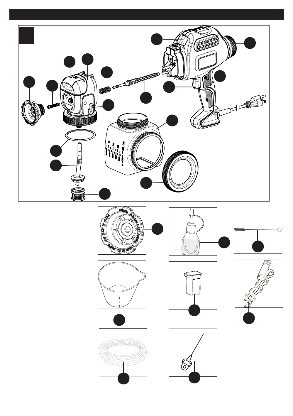
COMPOSANTS
A
14
16
15
6
7
DESCRIPCIÓN DE LAS
FUNCIONES
1.) Pulverizador de pintura
2.) Perilla de control de flujo
3.) Interruptor de control de
velocidad
4.) Gatillo
5.) Depósito de llenado lateral
6.) Junta tórica
7.) Tubo de recogida
8.) Filtro del tubo de recogida
9.) Tapa
10.) Émbolo
11.) Resorte del émbolo
12.) Ensamblaje del cuerpo de la
válvula
13.) Perilla para limpieza rápida
14.) Puerta para limpieza rápida
15.) Válvula atomizadora
16.) Boquilla tipo abanico (verde)
17.) Boquilla cónica (azul)
18.) Aceite lubricante
19.) Cepillo de limpieza
20.) Cubo para mezcla
21.) Vaso de llenado para limpieza
rápida
22.) Sujetador para lata de pintura
(BDPS600 únicamente)
23.) Manguera directo a la lata
(BDPS600 únicamente)
24.) Aguja de limpieza
12
11
13
8
20
23
10
9
3
17
4
5
21
24
40
1
18
2
19
22
Page 41

INSTALACIÓN
ADVERTENCIA: Asegúrese de usar
el equipo protector adecuado y desenchufe la
unidad.
B
B1
ADVERTENCIA: Asegúrese de que el
área esté bien ventilada y sin vapores
inflamables.
SELECCIÓN DE LA BOQUILLA DE
PULVERIZACIÓN ADECUADA
(FIGURAS B Y B1)
El pulverizador incluye dos boquillasestándar
que siguen un código de colores para
facilitar su identificación.
Boquilla tipo abanico (ancha) (verde;
Figura B): Esta boquilla tiene instalado un
resorte en la parte posterior que permite
realizar ajustes para pulverizar tanto vertical
como horizontalmente. Además, posee lengüetas en el costado que coinciden con el patrón de pulverización cuando
se ajustan para pulverizar de un lado a otro y de arriba a abajo. El patrón de pulverización cubre un área amplia.
Esta es la boquilla de pulverización que se identifica con el número 1 en el diagrama en la parte superior del pulverizador.
Boquilla cónica (azul; Figura B1): El patrón de pulverización de la boquilla cónica es más concentrado. Utilice esta
boquilla para elementos que son demasiado pequeños para la boquilla tipo abanico. Esta es la boquilla de
pulverización que se identifica con el número 2 en el diagrama que se encuentra en la parte superior del pulverizador.
INSTALACIÓN DE LAS BOQUILLAS DE
PULVERIZACIÓN (FIGURAS C Y C1)
Para instalar la boquilla de pulverización
tipo abanico verde:
• Asegúrese de que el cable esté desenchufado.
• Enrosque la boquilla sobre el eje hasta que
sienta una leve resistencia (alrededor de 10
vueltas completas).
• Empuje la boquilla accionada por resorte y
gírela hasta que se asiente por completo
(Figura C).
• Cuando la boquilla esté bien asentada, el
resorte en la parte posterior de la boquilla
hará que ésta salga levemente al soltarla
(Figura C1).
• Asegúrese de que la boquilla de pulverización
tipo abanico se haya enroscado por completo
(únicamente a mano). Si no está bien asentada
puede presentar fugas o la boquilla puede dañarse.
Para quitar la boquilla de pulverización verde tipo abanico:
• Empuje la boquilla y gírela hacia la izquierda.
Para instalar la boquilla de pulverización cónica azul:
• Enrosque la boquilla sobre el eje hasta que se asiente por completo.
• Asegúrese de que la boquilla de pulverización cónica se haya enroscado por completo (únicamente a mano). Si no
está bien asentada puede presentar fugas o la boquilla puede dañarse.
AJUSTE DE LA BOQUILLA DE
PULVERIZACIÓN TIPO ABANICO
(FIGURAS D Y D1)
Para ajustar la boquilla de pulverización
tipo abanico:
• Asegúrese de que el cable esté
desenchufado y que la boquilla de
pulverización tipo abanico se haya ajustado
a mano por completo.
• La boquilla de pulverización tipo abanico
posee dos lengüetas que se alinean para
indicar las posiciones vertical y horizontal.
• Si va a pulverizar de un lado a otro, ajuste
boquilla para alinear la marca vertical como
se muestra en la Figura D.
• Si va a pulverizar de arriba a abajo, ajuste
boquilla para alinear la marca horizontal
como se muestra en la Figura D1.
C
D
41
C1C1
D1
Page 42

PRECAUCIÓN: No comprima ni empuje el resorte cuando ajuste el patrón tipo abanico. La boquilla debe girar
y no soltarse.
PREPARACIÓN DE MATERIALES
LÍQUIDOS (FIGURAS E Y E1)
CONSEJO: Asegúrese de que el tipo de
material que utiliza se pueda limpiar con
alcoholes minerales o diluyente (para
pinturas a base de aceite) o una solución
de agua tibia y jabón (para pinturas
solubles en agua como el látex). Para
proteger los pisos y cualquier otra cosa
en el área de pulverización que desee
mantener intacta, utilice paños
atrapagotas al verter, mezclar y probar la
viscosidad de los materiales que se van a
pulverizar.
Es posible que se necesite diluir el líquido a
pulverizar antes de comenzar. Al diluir, utilice
el diluyente líquido apropiado recomendado
en el envase por el fabricante del material y en la proporción de dilución adecuada.
E
E1
ADVERTENCIA: No utilice materiales con un punto de ignición superior a 60 °C (140 °F).
Se proporciona un cubo para mezcla de 2,6 l (2-3/4 cuartos de galón) para transferir material de pulverización
desde el envase original al cubo para fines de dilución y medición (Figura E).
• Si el material necesita dilución, agregue el material diluyente líquido apropiado recomendado por el fabricante
(Figura E1).
• El vaso de llenado para limpieza rápida tiene una capacidad de 73,9 cc (2,5 onzas). Éste puede utilizarse como
una medida rápida para diluir al 5% en el depósito de llenado lateral.
• Es posible pulverizar pintura látex con esta unidad; sin embargo, la dilución requerida tal vez exceda la
recomendación del fabricante del material. El operador debe considerar el tipo de aplicación y la ubicación final del
proyecto al pulverizar.
PROPORCIONES COMUNES DE DILUCIÓN EN LATAS DE PINTURA
SUGERIDAS POR LOS FABRICANTES CENTÍMETROS CÚBICOS POR
3,8 LITROS (ONZAS POR GALÓN)
0,24 L (1/2 pinta) 237 cc (8 onzas)
5% 192 cc (6-1/2 onzas)
10% 384 cc (13 onzas)
CONSEJOS DE PREPARACIÓN
• En cada trabajo de pulverización, siempre debe asegurarse de haber preparado correctamente la superficie para
obtener el mejor acabado. Es decir, que todas las superficies estén libres de polvo, suciedad, óxido y grasa. Lave a
baja presión las cubiertas o las superficies exteriores y asegúrese de que estén secas antes de pulverizar.
• Se recomienda cubrir todos los bordes y demás áreas con cinta protectora y utilizar paños atrapagotas para prote-
ger los pisos y cualquier otra cosa en el área de pulverización que desee mantener intacta.
• La película que se forma en la parte superior de la pintura puede obstruir el pulverizador. Elimine la película antes de
mezclar. Si el material es antiguo, posiblemente necesite colarlo usando un embudo con filtro incorporado o a través
de calcetería para eliminar toda impureza que pudiera obstruir el sistema.
• Antes de comenzar, disponga de guantes, toallas de papel, trapos, etc.
para derrames inesperados.
LLENADO DEL DEPÓSITO (FIGURA F)
• Revise para asegurarse de que el depósito esté completamente en-
roscado sobre el pulverizador.
• Apoye el pulverizador sobre un costado con la tapa lateral del depósito
mirando hacia arriba.
• Desenrosque la tapa del costado del depósito.
• Vierta el material a pulverizar debidamente diluido y colado dentro del
depósito de llenado lateral (Figura F). CONSEJO: Utilice el cubo para
mezcla provisto para verter el material desde el envase original al
depósito de llenado lateral.
• Limpie todo residuo de líquido de las roscas o los lados del depósito y el
pulverizador.
• Con las roscas bien alineadas, enrosque la tapa completamente sobre
el depósito de llenado lateral. Revise la tapa para asegurarse de que esté
pareja y completamente enroscada antes de tomar el pulverizador.
42
F
Page 43

ALINEACIÓN DEL TUBO DE RECOGIDA
(FIGURAS F1 Y F2)
El tubo de recogida se puede alinear en la
dirección en la cual se realizará la mayor
parte de la pulverización para ayudar a
minimizar la cantidad de veces que deberá
rellenar el depósito.
• Si está pulverizando en un ángulo ascendente
o en forma recta, ubique el tubo de recogida.
(Figura F1) hacia la parte trasera del depósito.
• Si está pulverizando en un ángulo
descendente, ubique el tubo de recogida
(Figura F2) hacia la parte delantera del
depósito.
Esto asegurará que pulverice tanto material
como sea posible antes de que necesite
rellenar.
CONFIGURACIÓN OPCIONAL CON LA MANGUERA DIRECTO A LA LATA
(BDPS600 ÚNICAMENTE)
• Desenrosque el depósito del pulverizador
girando el collar como se muestra en la
Figura G y quite el tubo de recogida y el filtro
(Figura G1).
F1
G
F2
G1
• Empuje la manguera de succión sobre las
tomas de entrada y retorno como se muestra
(Figura G2).
• Separe las mangueras en el extremo
opuesto y deslice la más grande
completamente a través del sujetador para
envases y luego por encima de las
protuberancias del tubo de recogida y el filtro
como se muestra en la Figura G3.
• Coloque el ensamblaje del tubo de succión
dentro del envase del material e instale el
sujetador para envases firmemente en un
costado (Figura G4). Revise para
asegurarse de que el ensamblaje completo
esté sumergido en el envase del material.
G2
G4
G3
43
Page 44

AJUSTES DE CONTROL DE VELOCIDAD Y FLUJO
INTERRUPTOR DE CONTROL DE DOS VELOCIDADES (FIGURA H)
(MODELO BDPS600 ÚNICAMENTE)
El pulverizador cuenta con dos ajustes de velocidad distintos.
• Para cambiar las velocidades, oprima el lado derecho del interruptor. Un LED
indica el ajuste 1 ó 2.
• Utilice el ajuste de velocidad más baja (Ajuste 1) para lograr un mayor control
sobre el proyecto de pulverización, en tanto que la velocidad más alta (Ajuste 2) le
brinda una mayor cobertura en una menor cantidad de tiempo.
• El nivel de la velocidad más baja le permite acercarse más a su trabajo con una
menor sobrepulverización.
El ajuste bajo funciona bien con pinturas de cuerpo más ligero o más fluidas como
tintes y selladores.
• Las pinturas con un cuerpo más denso, como el látex a base de agua,
necesitarán el ajuste número 2.
• Utilice el ajuste del control de velocidad en conjunto con la perilla de control de
flujo y pruebe lo que funciona mejor con el material pulverizado.
Ajuste el control de flujo en un posición más baja o mediana (1 a 4) cuando la
velocidad esté en el ajuste 1.
Ajuste el control de flujo en un posición mediana o más alta (4 a 6) cuando la
velocidad esté en el ajuste 2.
PERILLA DE CONTROL DE FLUJO (FIGURA I)
La perilla de control de flujo regula la cantidad de líquido que se puede pulverizar.
• Seleccione bajo (1), mediano (5) o alto (9) con la perilla de control de flujo.
CONSEJO: Siempre pruebe el patrón de pulverización primero sobre cartón
desechable o un material similar. Comience con la perilla de control de flujo
en el ajuste de flujo más alto. Los materiales más pesados y más gruesos
deben pulverizarse con el ajuste más alto cercano al N.º 9.
Los materiales más delgados deben pulverizarse con el ajuste más bajo
cercano al N.º 1.
H
I
FUNCIONAMIENTO
GATILLO DE ENCENDIDO/APAGADO (FIGURA J)
El pulverizador se enciende y se paga mediante el gatillo.
• Para encender el pulverizador, oprima el gatillo.
• Para apagar el pulverizador, suelte el gatillo.
J
ADVERTENCIA: Riesgo de lesión. Nunca apunte el pulverizador a
ninguna parte del cuerpo. Nunca oprima el gatillo mientras regula el ajuste de
pulverización.
CEBADO CON LA MANGUERADIRECTO A LA LATA (BDPS600 ÚNICAMENTE)
• El tiempo necesario para cebar variará de 30 segundos a 3 minutos según la densidad del material que esté
pulverizando. Cuando el pulverizador está cebando o succionando la pintura en el uso inicial, produce un ruido fuerte;
esto es normal. Cuando el pulverizador esté cebado y pintando, el ruido disminuirá.
• Si el pulverizador está debidamente limpio y lubricado y demora más de tres minutos en cebarse, es posible que el
émbolo y/o la caja de la bomba estén gastados y será necesario reemplazarlos antes de utilizar la manguera directo a
la lata.
• El uso de la manguera directo a la lata reducirá el flujo del material, de manera que tomará más tiempo aplicar la
misma cantidad de material a la superficie pulverizada.
• Se recomienda un ciclo de trabajo al 75% al utilizar la manguera directo a la lata. Por ejemplo, acciones el gatillo del
pulverizador durante 15 segundos y luego permita que el pulverizador funcione en ralentí durante 5 segundos.
44
Page 45
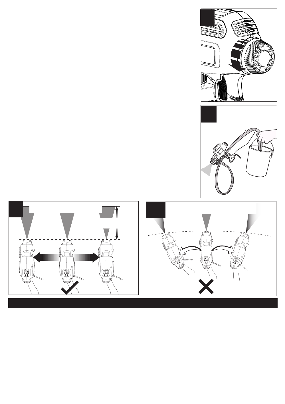
Si utiliza la manguera directo a la lata, deberá cebar el pulverizador mediante la
extracción de aire del sistema. Para cebar:
1. Asegúrese de que el pulverizador esté enchufado y gire la perilla de control de
flujo en sentido contrario a las agujas del reloj hasta el máximo (Figura K).
K
2. Sostenga el pulverizador por debajo del nivel de la pintura. Esto acelerará el
cebado (Figura L).
3. Apunte el pulverizador al trozo desechable de madera o cartón. Oprima el gatillo
y manténgalo así hasta que todo el aire salga del sistema y el material fluya con
libertad a través de la punta del pulverizador. Esto puede tomar hasta tres minutos.
Importante: El extremo de la manguera directo a la lata debe permanecer
completamente sumergido en el material. Si no está completamente sumergido y
se succiona aire hacia el sistema, el émbolo podría atascarse. Si el émbolo se
atasca, el sonido que produce el pulverizador cambiará a un zumbido bajo y el
pulverizador se calentará rápidamente al tacto. Nunca haga funcionar el
pulverizador cuando el émbolo esté atascado. En caso de que esto ocurra, limpie
minuciosamente el émbolo y la caja de la bomba utilizando los procedimientos de
limpieza indicados en este manual.
M
APLICACIÓN UNIFORME DE LA
PULVERIZACIÓN
M1
1 a 14 pulgadas
(25 a 35 mm)
APLICACIÓN DISPAREJA DE LA
L
PULVERIZACIÓN
DESARROLLO DE LA TÉCNICA DE PULVERIZACIÓN ADECUADA
• Practique la pulverización sobre una pieza de material desechable como un cartón para probar el patrón de
pulverización y familiarizarse con los ajustes de velocidad y las funciones de control de flujo del pulverizador.
• Asegúrese de que la superficie a pulverizar esté libre de polvo, suciedad y grasa.
• Asegúrese de que el área de pulverización esté limpia y libre de polvo que podría soplarse sobre las superficies
recién pintadas.
• Cubra todas las áreas que no vaya a pulverizar.
• Siempre pulverice desde una distancia mínima de 25 mm (1 pulgada) hasta una distancia máxima de 356 mm
(14 pulgadas) (Figura M). Por lo general, lo óptimo es alrededor de 254 mm (10 pulgadas) o utilice una varilla para
revolver pintura como referencia.
• Un método comúnmente utilizado para pulverizar una superficie grande es el patrón “entrecruzado”. Esto se hace
pulverizando en franjas horizontales y luego cruzando sobre éstas con franjas verticales.
• Para lograr una distribución uniforme de la pulverización, siempre mantenga su brazo a la misma distancia
(Figura M) de la superficie que pulveriza y evite mover su muñeca (Figura M1).
• Mantenga una velocidad suave y constante que le ayudará a evitar inconsistencias. Comience a pulverizar después
de iniciar la pasada y suelte el gatillo antes de terminar la pasada.
45
Page 46

• Evite pulverizar demasiado en una sola área. Varias capas más delgadas son mejores que una capa gruesa que
puede producir escurrimiento y goteo. Recuerde que la perilla de control de flujo regula la cantidad de líquido que se
puede pulverizar. Al girar la perilla de flujo en sentido contrario a las agujas del reloj se aumenta el flujo de líquido. Al
girar la perilla en el sentido de las agujas del reloj se reduce el flujo de líquido. Si se producen escurrimientos o
goteos, tenga a mano una brocha seca para emparejarlos.
ADVERTENCIA: PELIGRO DE DESCARGA ELÉCTRICA. Cuando pulverice por encima de su cabeza,
unca incline el pulverizador más de 45 grados. El material pulverizado podría filtrarse a la caja del motor.
n
CONSEJO: Si la válvula atomizadora no está debidamente asentada, el material pulverizado escapará por
detrás de la boquilla de pulverización. Si hay una fuga de material, apague y
desenchufe de inmediato el pulverizador de
la fuente de alimentación. Para corregir
este problema, siga los pasos a
continuación:
• Desenchufe el pulverizador de la fuente de
alimentación. Siga los pasos de “Cómo utilizar
el sistema de limpieza rápida” de la
página 47.
Si el problema persiste:
• Revise que el pulverizador esté
desenchufado de la fuente de alimentación.
Quite la boquilla de pulverización girándola en
sentido contrario a las agujas del reloj
(Figura N). Para la boquilla tipo abanico,
recuerde empujarla y girarla en sentido
contrario a las agujas del reloj para quitarla.
• Quite el atomizador y revise para ver si éste
necesita limpieza o reemplazo. Revise también
dentro de la caja de la bomba en busca de
residuos u obstrucciones, y límpiela si es
necesario (Figura N1).
N
N2
N1
N3
• Reemplace la válvula atomizadora,
asegurándose de que esté debidamente
asentada (Figura N2).
• Vuelva a enroscar la boquilla de pulverización
sobre el pulverizador girándolo en el sentido de
las agujas del reloj (Figura N3).
LIMPIEZA
ADVERTENCIA:
• Asegúrese de que el área de limpieza esté bien ventilada y libre de vapores inflamables.
• Siempre pulverice al aire libre cuando expulse la solución de limpieza a través del pulverizador.
• Para proteger los pisos y cualquier otra cosa en el área de pulverización que desee mantener intacta, utilice paños
atrapagotas al verter, mezclar y probar la viscosidad de los materiales que se van a pulverizar.
USO DEL SISTEMA DE LIMPIEZA RÁPIDA
El sistema de limpieza rápida ofrece una variedad de funciones útiles.
En primer lugar, el sistema puede permitirle pulverizar agua o un líquido de limpieza adecuado cuando aún se
encuentre material de pulverización en el depósito principal. Esto es útil al configurar el patrón de pulverización con la
boquilla tipo abanico. Usted puede pulverizar agua en lugar de gastar material de pulverización para apreciar el
patrón de pulverización.
En segundo lugar, el sistema de limpieza rápida le permite lavar el ensamblaje de la bomba, el émbolo, la boquilla y
la válvula atomizadora. Al pulverizar durante períodos prolongados, el material de pulverización puede acumularse
provocando un deterioro en la calidad de la pulverización. Es importante lavar este sistema con agua o líquido de
limpieza cada dos rellenados con material de pulverización. También es importante lavar el sistema cuando el
pulverizador va a estar en reposo durante más de 15 minutos sin uso. El material de pulverización puede secarse en
la boquilla y el ensamblaje de la bomba, y requeriría una limpieza exhaustiva. Siempre lubrique el émbolo si
permanece en reposo durante un período prolongado. Consulte la sección “Reensamblaje”.
En tercer lugar, el sistema de limpieza rápida permite una limpieza más rápida una vez terminado el proyecto. Uno o
dos lavados a través del sistema de limpieza rápida le ayudan a agilizar la limpieza de la boquilla, el atomizador, la
bomba y el émbolo. Siga los pasos de limpieza recomendados en este manual al realizar una limpieza final del
sistema.
Asegúrese de usar el equipo protector adecuado.
46
Page 47
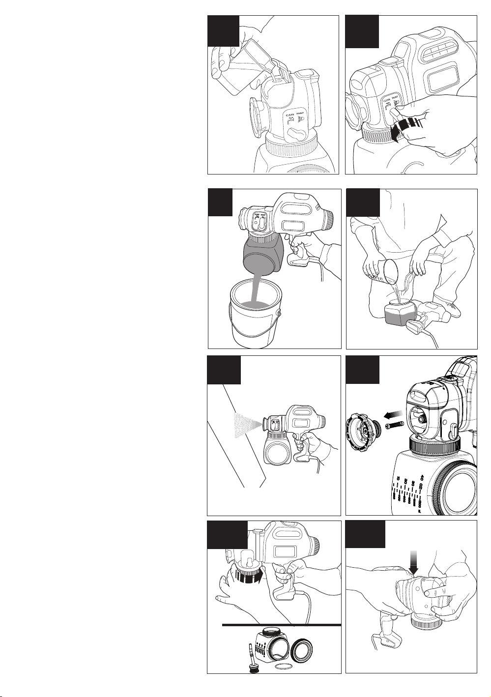
CÓMO UTILIZAR EL SISTEMA DE LIMPIEZA
1
2
RÁPIDA
• Desenchufe el pulverizador de la fuente de
alimentación.
• Llene el vaso de llenado para limpieza rápida,
hasta la línea de llenado de 95 ml, con agua o
la solución de limpieza adecuada.
• Abra la puerta para limpieza rápida y vierta la
solución de limpieza como se muestra en la
Figura O. No llene el depósito en exceso.
Mueva la palanca de limpieza rápida de
•
pintar” a “limpiar” (Figura O1).
“
• Enchufe el pulverizador.
• Pulverice dentro de un recipiente para
desechos, una caja de cartón o una superficie
de prueba para lavar el sistema del
pulverizador completamente.
• Una vez que el patrón de pulverización cambie
al color de la solución de limpieza, inicie la
limpieza.
• Es posible que necesite lavarlo más de una vez.
AVISO: Tenga presente que este no es el
paso final de la limpieza.
PARA INICIAR LA LIMPIEZA:
• Desenchufe el pulverizador de la fuente de
alimentación.
• Desenrosque la tapa del costado del depósito
y vierta todo el líquido restante de vuelta en el
envase original (Figura P).
• Vierta una cantidad pequeña de la solución de
limpieza adecuada dentro del depósito
(Figura P1).
• Agua tibia jabonosa para materiales a base
de agua.
• Solución de limpieza recomendada por el
fabricante para los materiales a base de aceite.
• Vuelva a colocar firmemente la tapa en el
depósito y agite el pulverizador vigorosamente.
• Desenrosque la tapa del costado del depósito
y deseche apropiadamente la solución de
limpieza.
• Rellene el depósito con una cantidad
pequeña de solución de limpieza nueva
(Figura P1). Enrosque la tapa firmemente
sobre el depósito.
• Enchufe el cable y pulverice la solución de
limpieza a través del pulverizador sobre
material desechable durante 5 segundos
(Figura P2).
• Desenchufe el pulverizador de la fuente de
alimentación.
• Deseche apropiadamente la solución de
limpieza.
• Quite la boquilla de pulverización girándola en
sentido contrario a las agujas del reloj y luego
quite el atomizador (Figura P3). Consulte las
Figuras C y C1.
• Desenrosque el depósito del pulverizador
girando el collar como se muestra en la
Figura P4. Quite el tubo de recogida, el filtro y la
junta tórica del pulverizador. Limpie las piezas
con el cepillo de limpieza en la solución de
limpieza apropiada.
• Quite la cubierta delantera del pulverizador
presionando hacia abajo el botón de liberación y
separando la cubierta delantera del pulverizador
(Figuras P5 y P6).
O
P
P2
P4
O1
P1
P3
P5
47
Page 48

• Quite el émbolo y el resorte (Figura P7).
• Limpie la boquilla de pulverización, el tubo de
recogida y el filtro, el atomizador, el émbolo y el
resorte con el cepillo de limpieza en la solución
de limpieza apropiada (Figura P8).
• Limpie minuciosamente
cámara del émbolo con el cepillo de limpieza
(Figura P9).
IMPORTANTE: Asegúrese de eliminar todo el
material del interior de la cámara del émbolo.
Una cantidad pequeña de material que no se
elimina con el cepillo de limpieza puede
endurecerse con el tiempo e interferir con el
movimiento del émbolo provocando daños en
el pulverizador.
el interior de la
P6
P8
P7
P9
• Asegúrese de que la perilla para limpieza
rápida esté orientada en la posición de
pulverización como se muestra en la
Figura P10 con una flecha.
• Limpie exhaustivamente el interior de las
aberturas de entrada y retorno con el cepillo de
limpieza (Figura P10).
IMPORTANTE: Además, limpie minuciosamente el orificio de ventilación más pequeño, que se muestra con una flecha en la
figura P11, con la aguja de limpieza incluida.
• Seque bien todas las piezas.
LIMPIEZA DE LA MANGUERA DIRECTO A
LA LATA
• Desenchufe el pulverizador de la fuente de
alimentación.
• Quite el tubo de succión del envase del
material y sumérjalo en un cubo
que contenga un disolvente adecuado para el
tipo de material que pulverizó (agua jabonosa
tibia para materiales a base de látex; solución
de limpieza recomendada por los fabricantes
para materiales a base de aceite) (Figura Q).
• Enchufe el pulverizador. Apunte el pulverizador hacia el costado de otro recipiente para
desechos. Accione el gatillo del pulverizador
hasta que el patrón de pulverización cambie al
color de la solución de limpieza (Figura Q1).
• Desenchufe el pulverizador de la fuente de
alimentación.
P10
Q
P11
Q1
48
Page 49

• Quite el tubo de las tomas de entrada y retorno (Figura Q2).
• Sostenga el tubo sobre el recipiente para desechos y permite que se drene
todo el líquido restante en la manguera.
REENSAMBLAJE
• Deslice el resorte sobre la parte delantera del
émbolo (Figura R).
• Inserte el émbolo y el resorte dentro de la
cubierta delantera (Figura R1).
R
Q2
R1
• Mientras oprime el botón de liberación, inserte
la cubierta delantera con el émbolo dentro del
pulverizador hasta que el botón de liberación
encaje en su lugar (Figura R2).
AVISO: La unidad no se podrá reensamblar
sin el pistón y el resorte en su lugar.
• Aplique una pocas gotas de aceite a través de
la abertura del cilindro. Inserte la válvula
atomizadora dentro de la cubierta delantera.
Enrosque la boquilla de pulverización sobre la
caja delantera y ajústela a mano (Figura R3).
• Con el aceite lubricante provisto, aplique unas
pocas gotas de aceite por las aberturas
de entrada y retorno del pulverizador como se
muestra en la Figura R4.
• Gire el control de limpieza rápida desde pintar
a limpiar y viceversa tres veces después de la
lubricación.
• Inserte el tubo de recogida dentro de la
abertura de entrada del pulverizador
(Figura R5).
R2
R4
R3
R5
49
Page 50

• Vuelva a enroscar el depósito en el pulverizador (Figura R6) asegurándose de
que las lengüetas del depósito queden alineadas con las lengüetas del collar
enroscado. La tapa de llenado lateral siempre debe estar en el costado izquierdo
del pulverizador.
R6
DETECCIÓN DE PROBLEMAS
Problema Causa posible Solución posible
• El material escurre o gotea. • Se está pulverizando demasiado • Reduzca el flujo de aire girando
material. la perilla de control de flujo.
• Seestápulverizandodemasiadolento. • Aumente la velocidad de aplicación.
• Seestápulverizando demasiadocerca. • Aumente la distancia desde la superficie.
• Viscosidad demasiado diluida. • Verifique la recomendación de dilución.
• Demasiada sobrepulverización. • El pulverizador está demasiado lejos • Reduzca la distancia a la superficie.
• Se expulsa poco o nada del • Boquilla/Punta de pulverización • Limpie las boquillas.
material. obstruida.
• Material pulverizado está • Viscosidad del material está muy alta. • Diluya el material según la recomendación
salpicando. del fabricante.
• El pulverizador vibra. • Material en el depósito casi agotado. • Rellene el depósito.
• El líquido se sale del depósito. • La tapa no está pareja o • Quite la tapa y vuelva a colocarla en forma
• El motor funciona correctamente • Error al cebar con tubo remoto. • Diluya el material de pulverización.
pero no pulveriza. Sostenga el pulverizador por debajo del
de la superficie.
• Se está pulverizando demasiado • Reduzcael flujogirando la perilla de control
material. de flujo en el sentido de las agujas de reloj.
• Tubo de recogida suelto u obstruido. • Revise el tubo.
• Ajuste demasiado bajo de la perillade • Aumente el ajuste de control de flujo.
control de flujo.
• Material demasiado espeso. • Verifique la recomendación de viscosidad.
suficientemente ajustada. pareja y uniforme, luego ajuste firmemente el
• Hay pintura en las roscas del • Limpie las roscas en la parte superior y los
depósito y del tapón. lados del depósito y el tapón.
• Tubo de succión suelto o dañado. • Ajuste o reemplace.
•
Válvulaatomizadoraobstruida o gastada.
• Falta válvula atomizadora. • Instale la válvula atomizadora.
• Material demasiado espeso. • Diluya el material.
• Punta de pulverización obstruida. • Limpie la punta.
• Filtro de entrada obstruido. • Limpie el filtro de entrada.
• La perilla de control necesita ajuste. • Ajuste la perilla.
• Émbolo gastado. • Limpie y lubrique o reemplace.
tapón.
nivel de la lata de material de pulverización.
Lubrique la abertura de entrada.
• Limpie o reemplace según sea necesario.
• Nosepuedereensamblarlaunidad. • Se omitió un paso del ensamblaje. • Inserte el resortey el pistón dentro de la
Solamente para Propósitos de México
Para conocer la ubicación del centro de servicio más cercano a fin de recibir ayuda con su producto, visite nuestro sitio Web
www.blackanddecker.com.mx o llame a la línea de ayuda BLACK & DECKER al 01 800 847 2309/01 800 847 2312
50
cubierta antes de reensamblar.
• Mantenga oprimido el botón de liberación
al reensamblar.
Page 51

MANTENIMIENTO
Para limpiar la unidad motriz, utilice únicamente jabón suave y un paño húmedo. Nunca permita que penetre ningún
líquido dentro de la unidad motriz; nunca sumerja ninguna pieza de la unidad motriz en un líquido.
IMPORTANTE: Para garantizar la SEGURIDAD y CONFIABILIDAD del producto, las reparaciones, el
mantenimiento y los ajustes (distintos de los enumerados en este manual) deben realizarse en los centros de
mantenimiento autorizados o en otras organizaciones de mantenimiento calificadas, siempre utilizando piezas de
repuesto idénticas.
ACCESORIOS
Los accesorios recomendados para uso con el producto están disponibles en su distribuidor local o centro de
mantenimiento autorizado. Si necesita ayuda con respecto a los accesorios, llame al: 1-800-544-6986.
ADVERTENCIA: El uso de cualquier accesorio no recomendado con este producto puede ser peligroso.
INFORMACIÓN DE MANTENIMIENTO
Todos los Centros de servicio de Black & Decker cuentan con personal altamente capacitado dispuesto a brindar a
todos los clientes un servicio eficiente y confiable en la reparación de herramientas eléctricas. Si necesita consejo
técnico, reparaciones o piezas de repuesto originales de fábrica, póngase en contacto con el centro de servicio de
Black & Decker más cercano a su domicilio. Para ubicar su centro de servicio local, consulte la sección “Herramientas
eléctricas” (Tools-Electric) de las páginas amarillas, llame al 1-800-544-6986 o visite nuestro sitio
www.blackanddecker.com.
ADVERTENCIA: El mantenimiento de la herramienta debe ser realizado únicamente por personal de
reparaciones calificado.
ADVERTENCIA: Al realizar el mantenimiento de una herramienta, utilice únicamente piezas de repuesto idénticas.
GARANTÍA
Garantía completa de dos años para uso en el hogar
Black & Decker (Estados Unidos) Inc. ofrece una garantía de dos años por cualquier defecto del material o de
fabricación de este producto. El producto defectuoso se reparará o reemplazará sin costo alguno de dos maneras.
La primera opción, el reemplazo, es devolver el producto al comercio donde se adquirió (siempre y cuando se trate de
un comercio participante). Las devoluciones deben realizarse conforme a la política de devolución del comercio
(generalmente, entre 30 y 90 días posteriores a la venta). Le pueden solicitar comprobante de compra. Consulte en el
comercio acerca de la política especial sobre devoluciones una vez excedido el plazo establecido.
La segunda opción es llevar o enviar el producto (con flete pago) a un Centro de servicio propio o autorizado de Black
& Decker para su reparación o reemplazo según nuestro criterio. Le pueden solicitar el comprobante de compra. Los
Centros de servicio autorizados y de propiedad de Black & Decker se detallan en la sección “Herramientas eléctricas”
(Tools-Electric) de las páginas amarillas de la guía telefónica.
Esta garantía no se extiende a los accesorios. Esta garantía le concede derechos legales específicos; usted puede
tener otros derechos que pueden variar según el estado o la provincia. Si tiene alguna pregunta, comuníquese con el
gerente del Centro de servicio de Black & Decker de su zona. Este producto no está diseñado para uso comercial.
AMÉRICA LATINA: esta garantía no se aplica a los productos que se venden en América Latina. Para los productos
que se venden en América Latina, debe consultar la información de la garantía específica del país que viene en el
empaque, llamar a la compañía local o visitar el sitio Web a fin de obtener esa información.
SOLAMENTE PARA PROPOSITOS DE MEXICO
Grupo Realsa en herramientas,
S.A. de C.V.
Súper Manzana 69 MZ.01 Lote 30
(Av. Torcasita)
Col. Puerto Juárez
Cancún, Quintana Roo
Tel. 01 998 884 72 27
Ferre Pat de Puebla, S.A. de C.V.
16 de Septiembre No. 6149
Col. El Cerrito
Puebla, Puebla
Tel. 01 222 264 12 12
Ferre Pat de Puebla, S.A. de C.V.
Ejército Mexicano No. 15
Col. Ejido 1ro. de Mayo
Boca del Rio, Veracruz
Tel. 01 229 167 89 89
Servicio de Fabrica Black & Decker,
S.A. de C.V.
Lázaro Cardenas No. 18
Col. Obrera
Distrito Federal
Tel. 55 88 95 02
PARA OTRAS LOCALIDADES LLAME AL 01 800 847 2309 o 01 800 847 2312.
Representaciones Industriales Robles,
S.A. de C.V.
Tezozomoc No. 89
Col. La Preciosa
Distrito Federal
Tel. 55 61 86 82
Gpo. Comercial de Htas. y Refacciones
de Occidente, S.A. de C.V.
Av. La Paz No. 1779
Col. Americana, S. Juaréz
Guadalajara, Jalisco
Tel. 01 33 38 25 69 78
Herramientas y Equipos Profesionales
Av. Colón 2915 Ote.
Col. Francisco I. Madero
Monterrey, Nvo. León
Tel. 01 81 83 54 60 06
Htas. Portátiles de Chihuahua,
S.A. de C.V.
Av. Universidad No. 2903
Col. Fracc. Universidad
Chihuahua, Chihuahua
Tel. 01 614 413 64 04
51
Fernando González Armenta
Bolivia No. 605
Col. Felipe Carrillo Puerto
Cd. Madero, Tampico
Tel. 01 833 221 34 50
Perfiles y Herramientas de Morelia
Gertrudis Bocanegra No. 898
Col. Ventura Puente
Morelia, Michoacán
Tel. 01 443 313 85 50
Enrique Robles
Av. de la Solidaridad No. 12713
Col. La Pradera
Irapuato, Guanajuato
Tel. 01 462 626 67 39
Hernández Martinez Jeanette
Prolongación Corregidora Nte.
No. 1104
Col. Arboledas
Queretaro, Qro.
Tel. 01 442 245 25 80
Page 52

· GARANTÍA BLACK & DECKER · BLACK & DECKER WARRANTY
. SOLAMENTE PARA PROPOSITOS DE MEXICO
Distributor Name · Sello firma del distribuidor
Date of purchase · Fecha de compra Invoice No. · No. de factura
RODUCT INFOMATION · IDENTIFICACIÓN DEL PRODUCTO
P
Cat. No. · Catalogo ó Modelo Serial Number · No. de serie
Name · Nombre Last Name · Apellido
Address · Dirección
City · Ciudad State · Estado
Postal Code · Código Postal Country · País
Telephone · No. Teléfono
2 AÑOS DE GARANTIA
Este producto cuenta con dos años de garantía a partir de la fecha de compra contra
cualquier defecto de su funcionamiento, así como cualquier falla debido a materiales
empleados para su fabricación ó mano de obra defectuosa.
Nuestra garantía incluye la reparación o reposición del producto y/o componentes sin cargo
alguno para el cliente incluyendo la mano de obra, esta incluye los gastos de trasportación
erogados para lograr cumplimiento de esta garantía en los domicilios diversos señalados.
Para hacer efectiva esta garantía deberá presentar su herramienta y esta póliza sellada por
el establecimiento comercial donde se adquirió el producto.
Nos comprometemos a entregar el producto en un lapso no mayor a 30 días hábiles
contados a partir de la fecha de recepción del mismo en nuestros talleres de servicio
autorizados.
ESTA GARANTIA NO APLICA CUANDO:
El producto se hubiese utilizado en condiciones distintas a las normales.
El producto no hubiese sido operado de acuerdo con el instructivo de uso que se acompaña.
El producto hubiese sido alterado o reparado por personas no autorizadas por nosotros.
Importador: Black & Decker S.A. de .C.V
Bosque de Cidros Acceso Radiatas No.42
3ra.Seccion de Bosques de las lomas
C.P.05120, Mexico, D.F. Tel: (01 55) 5326 7100
Vea “Herramientas
eléctricas (Tools-Electric)”
– Páginas amarillas –
para Servicio y ventas
BOSQUES DE CIDROS ACCESO RADIATAS NO. 42
BLACK & DECKER S.A. DE C.V.
COL. BOSQUES DE LAS LOMAS.
05120 MÉXICO, D.F
TEL. (01 55) 5326 7100
01 800 847 2309/01 800 847 2312
Cat No. BDPS400, BDPS600 Form No. 90572158 SEPTEMBER 2011
Copyright © 2011 Black & Decker Printed in China
52
 Loading...