

Page 1

VEA EL ESPAÑOL EN LA CONTRAPORTADA.
POUR LE FRANÇAIS, VOIR LA COUVERTURE ARRIÈRE.
SAVE THIS MANUAL FOR FUTURE REFERENCE.
INSTRUCTIVO DE OPERACIÓN, CENTROS DE SERVICIO Y
PÓLIZA DE GARANTÍA. ADVERTENCIA: LÉASE ESTE
INSTRUCTIVO ANTES DE USAR EL PRODUCTO.
INSTRUCTION MANUAL
BBBBDDDDMMMMSSSS111100000000 11110000”””” ((((222255554444MMMMMMMM)))) CCCCOOOOMMMMPPPPOOOOUUUUNNNNDDDD MMMMIIIITTTTEEEERRRR SSSSAAAAWW
WW
BEFORE RETURNING THIS PRODUCT FOR ANY REASON
PLEASE CALL 1-800-HOW-TO (544-6986)
IF YOU SHOULD EXPERIENCE A PROBLEM WITH YOUR BLACK & DECKER PRODUCT,
CALL 1-800-54-HOW-TO (544-6986).
BEFORE YOU CALL, HAVE THE FOLLOWING INFORMATION AVAILABLE, CATALOG No.,
TYPE No., AND DATE CODE. IN MOST CASES, A BLACK & DECKER REPRESENTATIVE
CAN RESOLVE THE PROBLEM OVER THE PHONE. IF YOU HAVE A SUGGESTION OR COMMENT,
GIVE US ACALL.YOUR FEEDBACK IS VITAL TO BLACK & DECKER.
Page 2

TABLE OF CONTENTS
IMPORTANT SAFETY INSTRUCTIONS . . . . . . . . . . . . . . . . . . . . . . . . . . . . . . . . . . . . . . . . . . . . . . . . . . . . . . . . . . .2
SAFETY GUIDELINES . . . . . . . . . . . . . . . . . . . . . . . . . . . . . . . . . . . . . . . . . . . . . . . . . . . . . . . . . . . . . . . . . . . . . . . .3
GENERAL SAFETY RULES . . . . . . . . . . . . . . . . . . . . . . . . . . . . . . . . . . . . . . . . . . . . . . . . . . . . . . . . . . . . . . . . . . . .4
ADDITIONAL SPECIFIC SAFETY RULES . . . . . . . . . . . . . . . . . . . . . . . . . . . . . . . . . . . . . . . . . . . . . . . . . . . . . . . . .5
CARTON CONTENTS . . . . . . . . . . . . . . . . . . . . . . . . . . . . . . . . . . . . . . . . . . . . . . . . . . . . . . . . . . . . . . . . . . . . . . . . .7
FUNCTIONAL DESCRIPTION . . . . . . . . . . . . . . . . . . . . . . . . . . . . . . . . . . . . . . . . . . . . . . . . . . . . . . . . . . . . . . . . . .8
ASSEMBLY . . . . . . . . . . . . . . . . . . . . . . . . . . . . . . . . . . . . . . . . . . . . . . . . . . . . . . . . . . . . . . . . . . . . . . . . . . . . . . . . .9
OPERATION . . . . . . . . . . . . . . . . . . . . . . . . . . . . . . . . . . . . . . . . . . . . . . . . . . . . . . . . . . . . . . . . . . . . . . . . . . . . . . .11
MAINTENANCE . . . . . . . . . . . . . . . . . . . . . . . . . . . . . . . . . . . . . . . . . . . . . . . . . . . . . . . . . . . . . . . . . . . . . . . . . . . . .20
SERVICE . . . . . . . . . . . . . . . . . . . . . . . . . . . . . . . . . . . . . . . . . . . . . . . . . . . . . . . . . . . . . . . . . . . . . . . . . . . . . . . . . .21
TROUBLESHOOTING . . . . . . . . . . . . . . . . . . . . . . . . . . . . . . . . . . . . . . . . . . . . . . . . . . . . . . . . . . . . . . . . . . . . . . .22
ACCESSORIES . . . . . . . . . . . . . . . . . . . . . . . . . . . . . . . . . . . . . . . . . . . . . . . . . . . . . . . . . . . . . . . . . . . . . . . . . . . .22
WARRANTY . . . . . . . . . . . . . . . . . . . . . . . . . . . . . . . . . . . . . . . . . . . . . . . . . . . . . . . . . . . . . . . . . . . . . . . . . . . . . . . .22
Read and understand all warnings and operating instructions before using any tool or equipment. When
using tools or equipment, basic safety precautions should always be followed to reduce the risk of personal injury.
Improper operation, maintenance or modification of tools or equipment could result in serious injury and property
damage. There are certain applications for which tools and equipment are designed. Black & Decker strongly
recommends that this product NOT be modified and/or used for any application other than for which it was designed.
IMPORTANT SAFETY INSTRUCTIONS
SAVE THESE INSTRUCTIONS!
Page 3

Indicates an imminently hazardous situation which, if not avoided, will result in death or serious injury.
Indicates a potentially hazardous situation which, if not avoided, could result in death or serious injury.
Indicates a potentially hazardous situation which, if not avoided, may result in minor or moderate injury.
Used without the safety alert symbol indicates potentially hazardous situation which, if not avoided, may
result in property damage.
It is important for you to read and understand this manual. The information it contains relates to protecting YOUR
SAFETY and PREVENTING PROBLEMS. The symbols below are used to help you recognize this information.
SAFETY GUIDELINES - DEFINITIONS
CALIFORNIA PROPOSITION 65
Some dust created by power sanding, sawing, grinding, drilling, and other construction activities contains
chemicals known to cause cancer, birth defects or other reproductive harm. Some examples of these
chemicals are:
• lead from lead-based paints,
• crystalline silica from bricks and cement and other masonry products, and
• arsenic and chromium from chemically-treated lumber (CCA).
Your risk from these exposures varies, depending on how often you do this type of work. To reduce your exposure to these
chemicals: work in a well ventilated area, and work with approved safety equipment, such as those dust masks that are specially
designed to filter out microscopic particles.
• Avoid prolonged contact with dust from power sanding, sawing, grinding, drilling, and other construction activities. Wear protective
clothing and wash exposed areas with soap and water. Allowing dust to get into your mouth, eyes, or lay on the skin may promote
absorption of harmful chemicals.
Use of this tool can generate and/or disperse dust, which may cause serious and permanent respiratory or
other injury. Always use NIOSH/OSHA approved respiratory protection appropriate for the dust exposure. Direct particles away from
face and body.
Wear appropriate hearing protection during use. Under some conditions and duration of use, noise from this
product may contribute to hearing loss.
For your convenience and safety, the following warning labels are on your miter saw.
ON MOTOR HOUSING:
WARNING: FOR YOUR OWN SAFETY, READ INSTRUCTION MANUAL BEFORE OPERATING SAW. WHEN SERVICING, USE
ONLY IDENTICAL REPLACEMENT PARTS. ALWAYS WEAR EYE PROTECTION.
ON FENCE:
CLAMP SMALL PIECES BEFORE CUTTING. SEE MANUAL.
ON GUARD:
DANGER – KEEP AWAY FROM BLADE.
ON GUARD RET
AINER PLATE: “PROPERLY SECURE BRACKET WITH BOTH SCREWS BEFORE USE.”
ALWAYS TIGHTEN ADJUSTMENT KNOBS BEFORE USE. KEEP HANDS 6" FROM PATH OF SAW BLADE. NEVER PERFORM
ANY OPERATION FREEHAND. NEVER CROSS ARMS IN FRONT OF BLADE. THINK! YOU CAN PREVENTACCIDENTS. DO NOT
OPERATE SAW WITHOUT GUARDS IN PLACE. NEVER REACH IN BACK OF SAW BLADE. ALWAYS WEAR EYE PROTECTION.
SHUT OFF POWER AND WAIT FOR BLADE TO STOP BEFORE SERVICING, ADJUSTING TOOL, OR MOVING HANDS.
ON TABLE: (2 PLACES)
Page 4

GENERAL SAFETY RULES
READ AND UNDERSTAND ALL WARNINGS AND OPERATING INSTRUCTIONS BEFORE
USING THIS EQUIPMENT. Failure to follow all instructions listed below, may result in
electric shock, fire, and/or serious personal injury or property damage.
IMPORTANT SAFETY INSTRUCTIONS
1. FOR YOUR OWN SAFETY, READ THE
INSTRUCTION MANUAL BEFORE OPERATING
THE MACHINE. Learning the machine’s
application, limitations, and specific hazards will
greatly minimize the possibility of accidents and
injury.
2. USE CERTIFIED SAFETY EQUIPMENT. Eye
protection equipment should comply with ANSI
Z87.1 standards, hearing equipment should
comply with ANSI S3.19 standards, and dust
mask protection should comply with
MSHA/NIOSH certified respirator standards.
Splinters, air-borne debris, and dust can cause
irritation, injury, and/or illness.
3. DRESS PROPERLY. Do not wear tie, gloves, or
loose clothing. Remove watch, rings, and other
jewelry. Roll up your sleeves. Clothing or jewelry
caught in moving parts can cause injury.
4. DO NOT USE THE MACHINE IN A
DANGEROUS ENVIRONMENT. The use of
power tools in damp or wet locations or in rain
can cause shock or electrocution. Keep your
work area well-lit to prevent tripping or placing
arms, hands, and fingers in danger.
5. MAINTAIN ALL TOOLS AND MACHINES IN PEAK
CONDITION. Keep tools sharp and clean for best and
safest performance. Follow instructions for lubricating
and changing accessories. Poorly maintained tools and
machines can further damage the tool or machine
and/or cause injury.
6. CHECK FOR DAMAGED PARTS. Before using the
machine, check for any damaged parts. Check
for alignment of moving parts, binding of moving
parts, breakage of parts, and any other
conditions that may affect its operation. A guard
or any other part that is damaged should be
properly repaired or replaced. Damaged parts
can cause further damage to the machine and/or
injury.
7. KEEP THE WORK AREA CLEAN. Cluttered areas and
benches invite accidents.
8. KEEP CHILDREN AND VISITORS AWAY. Your shop is
a potentially dangerous environment. Children and
visitors can be injured.
9. REDUCE THE RISK OF UNINTENTIONAL
STARTING. Make sure that the switch is in the
“OFF” position before plugging in the power cord.
In the event of a power failure, move the switch
to the “OFF” position. An accidental start-up can
cause injury.
10. USE THE GUARDS. Check to see that all guards
are in place, secured, and working correctly to
prevent injury.
11. REMOVE ADJUSTING KEYS AND WRENCHES
BEFORE STARTING THE MACHINE. Tools,
scrap pieces, and other debris can be thrown at
high speed, causing injury.
12. USE THE RIGHT MACHINE. Don’t force a
machine or an attachment to do a job for which it
was not designed. Damage to the machine
and/or injury may result.
13. USE RECOMMENDED ACCESSORIES. The use
of accessories and attachments not recommended by Black & Decker may cause damage
to the machine or injury to the user.
14. USE THE PROPER EXTENSION CORD. Make
sure your extension cord is in good condition.
When using an extension cord, be sure to use
one heavy enough to carry the current your
product will draw. An undersized cord will cause
a drop in line voltage, resulting in loss of power
and overheating. See the Extension Cord Chart
for the correct size depending on the cord length
and nameplate ampere rating. If in doubt, use the
next heavier gauge. The smaller the gauge
number, the heavier the cord.
15. SECURE THE WORKPIECE. Use clamps or vise
when you cannot secure the workpiece on the
table and against the fence by hand or when your
hand will be dangerously close to the blade (within
6”).
16. DON’T FORCE THE WORKPIECE ON THE
MACHINE. Damage to the machine and/or injury
may result.
17. DON’T OVERREACH. Loss of balance can make
you fall into a working machine, causing injury.
18. NEVER STAND ON THE MACHINE. Injury could occur
if the tool tips, or if you accidentally contact the cutting
tool.
19. NEVER LEAVE THE MACHINE RUNNING
UNATTENDD. TURN THE POWER OFF. Don’t leave
the machine until it comes to a complete stop. A child or
visitor could be injured.
20. TURN THE MACHINE “OFF”, AND DISCONNECT
THE MACHINE FROM THE POWER SOURCE before
installing or removing accessories, before
adjusting or changing set-ups, or when making
repairs. An accidental start-up can cause injury.
21. MAKE YOUR WORKSHOP CHILDPROOF WITH
PADLOCKS, MASTER SWITCHES, OR BY
REMOVING STARTER KEYS. The accidental
start-up of a machine by a child or visitor could
cause injury.
22. STAY ALERT, WATCH WHAT YOU ARE DOING,
AND USE COMMON SENSE. DO NOT USE THE
MACHINE WHEN YOU ARE TIRED OR UNDER
THE INFLUENCE OF DRUGS, ALCOHOL, OR
MEDICATION. A moment of inattention while
operating power tools may result in injury.
23. THE DUST GENERATED by certain woods and
wood products can be injurious to your health.
Always operate machinery in well-ventilated areas,
and provide for proper dust removal. Use wood
dust collection systems whenever possible.
Page 5

FAILURE TO FOLLOW THESE RULES MAY RESULT IN SERIOUS PERSONAL INJURY.
ADDITIONAL SPECIFIC SAFETY RULES
SAVE THESE INSTRUCTIONS.
Refer to them often and use them to instruct others.
1. DO NOT OPERATE THIS MACHINE until it is
completely assembled and installed according to the
instructions. A machine incorrectly assembled can
cause serious injury.
2. OBTAIN ADVICE FROM another qualified person if
you are not familiar with the operation of this machine.
3. FOLLOW ALL WIRING CODES and recommended
electrical connections to prevent shock or
electrocution.
4. SECURE THE MACHINE TO A SUPPORTING SURFACE.
Vibration can possibly cause the machine to slide,
walk, or tip over, causing serious injury.
5. USE ONLY CROSSCUT SAW BLADES. Use only
zero-degree or negative hook angles when using
carbide-tipped blades. Do not use blades with deep
gullets. These can deflect and contact the guard, and
can cause damage to the machine and/or serious
injury.
6. USE ONLY BLADES OF THE CORRECT SIZE AND
TYPE specified for this tool to prevent damage to the
machine and/or serious injury.
7. USE A SHARP BLADE. Check the blade to see if it
runs true and is free from vibration. A dull blade or a
vibrating blade can cause damage to the machine
and/or serious injury.
8. INSPECT BLADE FOR CRACKS or other damage
prior to operation. A cracked or damaged blade can
come apart and pieces can be thrown at high speeds,
causing serious injury. Replace cracked or damaged
blades immediately.
9. CLEAN THE BLADE AND BLADE FLANGES prior to
operation. Cleaning the blade and flanges allows you
to check for any damage to the blade or flanges. A
cracked or damaged blade or flange can come apart
and pieces can be thrown at high speeds, causing
serious injury.
10. USE ONLY BLADE FLANGES specified for this tool
to prevent damage to the machine and/or serious
injury.
11. CLEAR THE AREA OF FLAMMABLE LIQUIDS
and/or gas prior to operation. Sparks can occur that
would ignite the liquids and cause a fire or an
explosion.
12. CLEAN THE MOTOR AIR SLOTS of chips and
sawdust. Clogged motor air slots can cause the
machine to overheat, damaging the machine and
possibly causing a short which could cause serious
injury.
13. TIGHTEN THE TABLE CLAMP HANDLE and any
other clamps prior to operation. Loose clamps can
cause parts or the workpiece to be thrown at high
speeds.
14. NEVER START THE TOOL with the blade against the
workpiece. The workpiece can be thrown, causing
serious injury.
15. KEEP ARMS, HANDS, AND FINGERS away from the
blade to prevent severe cuts. Clamp all workpieces
that would cause your hand to be in the “Table
Hazard Zone” (within the red lines).
16. WHEN CUTTING WITH A COMPOUND SLIDING
MITER SAW, PUSH THE SAW FORWARD (AWAY
FROM YOU) and toward the fence. Pulling the saw
toward you can cause the saw to kick upward and
toward you.
17. WHEN USING A SLIDING MITER SAW AS A REGULAR
MITER SAW, LOCK THE SLIDE MECHANISM IN PLACE.
If the slide mechanism is not locked, the saw can kick
back toward you.
18. ALLOW THE MOTOR TO COME TO FULL SPEED
prior to starting cut. Starting the cut too soon can
cause damage to the machine or blade and/or
serious injury.
19. NEVER REACH AROUND or behind the saw blade.
A moving blade can cause serious injury.
20. NEVER CUT FERROUS METALS or masonry. Either
of these can cause the carbide tips to fly off the blade
at high speeds causing serious injury.
21. NEVER CUT SMALL PIECES. Cutting small pieces
can cause your hand to move into the blade, resulting
in serious injury.
22. NEVER LOCK THE SWITCH in the “ON” position.
Setting up the next cut could cause your hand to
move into the blade, resulting in severe injury.
23. NEVER APPLY LUBRICANT to a running blade.
Applying lubricant could cause your hand to move
into the blade, resulting in serious injury.
24. DO NOT PERFORM FREE-HAND OPERATIONS.
Hold the work firmly against the fence and table.
Free-hand operations on a miter saw could cause the
workpiece to be thrown at high speeds, causing
serious injury. Use clamps to hold the work when
possible.
25. AFTER COMPLETING CUT, release power switch
and wait for coasting blade to come to a complete
stop before returning saw to raised position. A
moving blade can cause serious injury.
26. TURN OFF THE MACHINE and allow the blade to
come to a complete stop prior to cleaning the blade
area or removing debris in the path of the blade. A
moving blade can cause serious injury.
27. TURN OFF MACHINE and allow the blade to come
to a complete stop before removing or securing
workpiece, changing workpiece angle, or changing
the angle of the blade. A moving blade can cause
serious injury.
28. PROPERLY SUPPORT LONG OR WIDE WORK-
PIECES. Loss of control of the workpiece can cause injury.
29. NEVER PERFORM LAYOUT, ASSEMBLY, OR SET-UP
WORK on the table/work area when the machine is
running. A sudden slip could cause a hand to move
into the blade. Severe injury can result.
30. TURN THE MACHINE “OFF”, disconnect the
machine from the power source, and clean the
table/work area before leaving the machine. LOCK
THE SWITCH IN THE “OFF” POSITION to prevent
unauthorized use. Someone else might accidentally
start the machine and cause injury to themselves.
32. BEFORE OPERATING THE SAW, check and
securely lock the bevel, miter, and sliding fence
adjustments.
33. ADDITIONAL INFORMATION regarding the safe and
proper operation of power tools (i.e. a safety video) is
available from the Power Tool Institute, 1300 Sumner
Avenue, Cleveland, OH 44115-2851
(www.powertoolinstitute.com). Information is also
available from the National Safety Council, 1121
Spring Lake Drive, Itasca, IL 60143-3201. Please refer
to the American National Standards Institute ANSI
01.1 Safety Requirements for Woodworking
Machines and the U.S. Department of Labor
regulations.
Page 6
A separate electrical circuit should be used for your machines. This circuit should not be less than #12 wire and should
be protected with a 20 Amp time lag fuse. If an extension cord is used, use only 3-wire extension cords which have 3prong grounding type plugs and matching receptacle which will accept the machine’s plug. Before connecting the
machine to the power line, make sure the switch (s) is in the “OFF” position and be sure that the electric current is of
the same characteristics as indicated on the machine. All line connections should make good contact. Running on low
voltage will damage the machine.
DO NOT EXPOSE THE MACHINE TO RAIN OR OPERATE THE MACHINE IN DAMP LOCATIONS.
GROUNDED OUTLET BOX
CURRENT
CARRYING
PRONGS
GROUNDING BLADE
IS LONGEST OF THE 3 BLADES
GROUNDED OUTLET BOX
GROUNDING
MEANS
ADAPTER
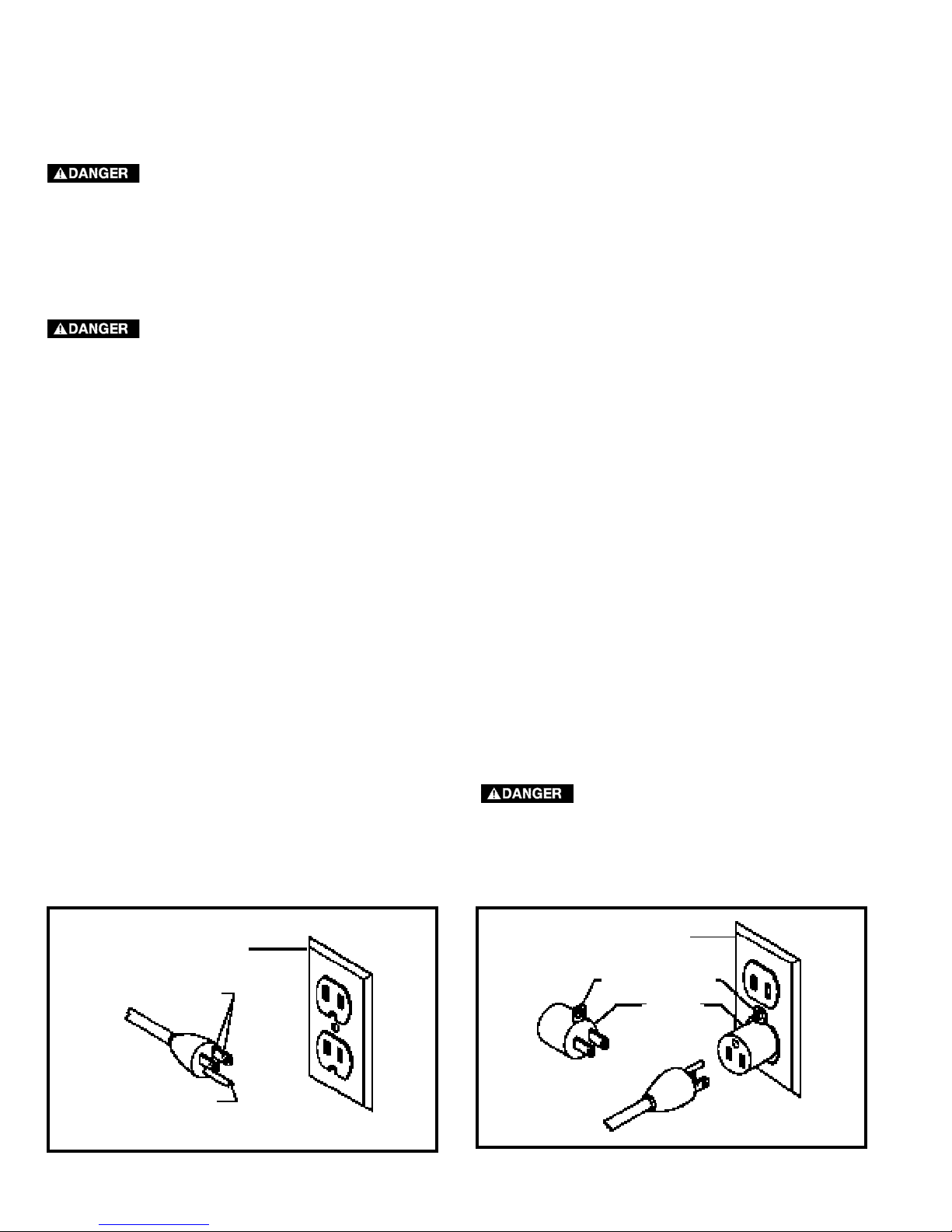
2. Grounded, cord-connected machines intended for
use on a supply circuit having a nominal rating less
than 150 volts:
If the machine is intended for use on a circuit that has an
outlet that looks like the one illustrated in Fig. A, the
machine will have a grounding plug that looks like the plug
illustrated in Fig. A. A temporary adapter, which looks like
the adapter illustrated in Fig. B, may be used to connect
this plug to a matching 2-conductor receptacle as shown
in Fig. B if a properly grounded outlet is not available. The
temporary adapter should be used only until a properly
grounded outlet can be installed by a qualified electrician.
The green-colored rigid ear, lug, and the like, extending
from the adapter must be connected to a permanent
ground such as a properly grounded outlet box. Whenever
the adapter is used, it must be held in place with a metal
screw.
NOTE: In Canada, the use of a temporary adapter is not
permitted by the Canadian Electric Code.
IN ALL CASES, MAKE CERTAIN THE
RECEPTACLE IN QUESTION IS PROPERLY
GROUNDED. IF YOU ARE NOT SURE HAVE A
QUALIFIED ELECTRICIAN CHECK THE
RECEPTACLE.
1. All grounded, cord-connected machines:
In the event of a malfunction or breakdown, grounding
provides a path of least resistance for electric current to
reduce the risk of electric shock. This machine is
equipped with an electric cord having an equipmentgrounding conductor and a grounding plug. The plug must
be plugged into a matching outlet that is properly installed
and grounded in accordance with all local codes and
ordinances.
Do not modify the plug provided - if it will not fit the outlet,
have the proper outlet installed by a qualified electrician.
Improper connection of the equipment-grounding
conductor can result in risk of electric shock. The
conductor with insulation having an outer surface that is
green with or without yellow stripes is the equipmentgrounding conductor. If repair or replacement of the
electric cord or plug is necessary, do not connect the
equipment-grounding conductor to a live terminal.
Check with a qualified electrician or service personnel if
the grounding instructions are not completely
understood, or if in doubt as to whether the machine is
properly grounded.
Use only 3-wire extension cords that have 3-prong
grounding type plugs and matching 3-conductor
receptacles that accept the machine’s plug, as shown in
Fig. A.
Repair or replace damaged or worn cord immediately.
POWER CONNECTIONS
MOTOR SPECIFICATIONS
Your machine is wired for 120 volts, 60 HZ alternating current. Before connecting the machine to the power source,
make sure the switch is in the “OFF” position.
GROUNDING INSTRUCTIONS
THIS MACHINE MUST BE GROUNDED WHILE IN USE TO PROTECT THE OPERATOR FROM
ELECTRIC SHOCK.
Page 7

Remove the miter saw and all loose items from the carton.
Do not lift the miter saw by the switch handle. This action can cause misalignment. Always lift the machine
by the base or the carrying handle.
1. Miter Saw
2. Dust Bag
3. 1/2" Blade Wrench
4. 5mm Hex Wrench
5. Table Lock Handle
ASSEMBLY
ASSEMBLY TOOLS REQUIRED
(Supplied)
* 5mm hex wrench
* 1/2” Blade wrench
(Not supplied)
* Phillips head screwdriver
* A square to make adjustments
UNPACKING AND CLEANING
Carefully unpack the machine and all loose items from the shipping container(s). Remove the protective coating from all unpainted
surfaces. This coating may be removed with a soft cloth moistened with kerosene (do not use acetone, gasoline or lacquer thinner for
this purpose). After cleaning, cover the unpainted surfaces with a good quality household floor paste wax.
CARTON CONTENTS
2
3
4 5
1
Fig. 2
Fig. 1
Page 8

FOREWORD
Model BDMS100 is a 10" Compound Power Miter Saw designed to cut wood, plastic, and aluminum. Compound angle
and bevel cutting are easy and accurate. It can crosscut up to 5-3/4" x 2-3/8", miter at 45° both left and right up to 41/8" x 2-3/8", bevel at 45° left up to 5-7/8" x 1-9/16", and compound 45° x 45°,4-1/8" x 1-9/16". It has positive miter
stops at 0°, 22.5°, 31.62°, and 45° both left and right, and bevel stops at 0° and 45° adjustable. A dust bag is included
to catch fine dust and wood chips.
FUNCTIONAL DESCRIPTION
EXTENSION CORDS
Use proper extension cords. Make sure your extension cord is in good condition and is a 3-wire
extension cord which has a 3-prong grounding type plug and matching receptacle which will accept the machine’s
plug. When using an extension cord, be sure to use one heavy enough to carry the current of the machine. An
undersized cord will cause a drop in line voltage, resulting in loss of power and overheating. Fig.3 shows the correct
gauge to use depending on the cord length. If in doubt, use the next heavier gauge. The smaller the gauge number,
the heavier the cord.
MINIMUM GAUGE EXTENSION CORD
RECOMMENDED SIZES FOR USE WITH STATIONARY ELECTRIC MACHINES
Ampere Total Length Gauge of
Rating Volts of Cord in Feet Extension Cord
0-6 120
up to
25 18 AWG
0-6 120 25-50 16 AWG
0-6 120 50-100 16 AWG
0-6 120 100-150 14 AWG
6-10 120
up to
25 18 AWG
6-10 120 25-50 16 AWG
6-10 120 50-100 14 AWG
6-10 120 100-150 12 AWG
10-12 120
up to
25 16 AWG
10-12 120 25-50 16 AWG
10-12 120 50-100 14 AWG
10-12 120 100-150 12 AWG
12-16 120
up to
25 14 AWG
12-16 120 25-50 12 AWG
12-16 120
GREATER THAN 50 FEET NOT RECOMMENDED
NOTICE: The photo on the manual cover illustrates the current production model. All other illustrations contained in
the manual are representative only and may not depict the actual color, labeling, or accessories, and are intended to
illustrate technique only.
Fig. 3
Page 9
For your own safety, do not connect the machine to the power source until the machine is
completely assembled and you read and understand the entire instruction manual.
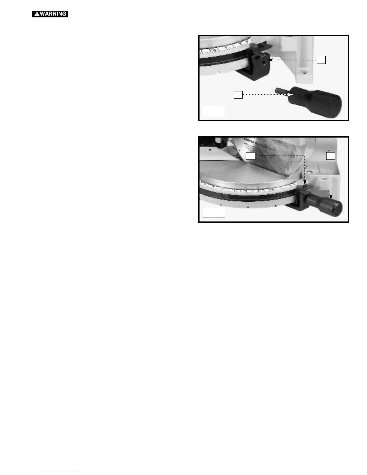
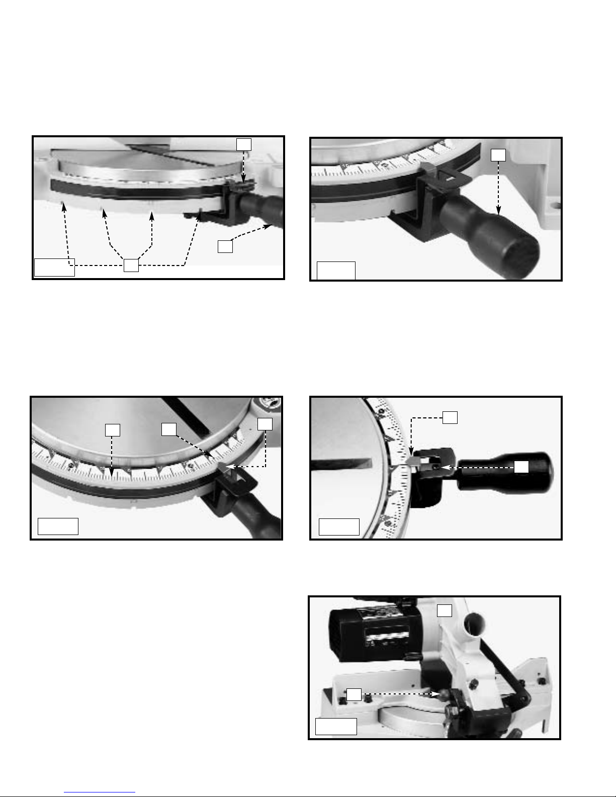
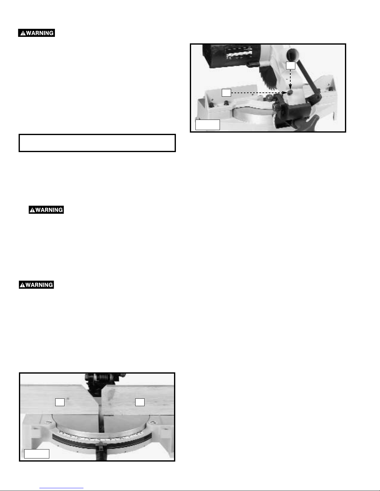
Thread the table lock handle (A) Fig. 4 into the threaded hole (B)
of the arm bracket.
1. Turn the table lock handle (A) Fig. 5 counter-clockwise one
or two turns, and depress the index lever (B) to release the
45° positive stop.
B
A
Fig. 4
ROTATING THE TABLE TO THE 90° DEGREE POSITION
Fig. 5
A
B
Page 10
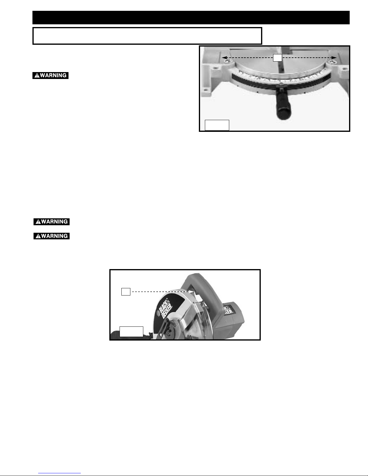
FASTENING THE MACHINE TO A SUPPORTING SURFACE
Before operating your compound miter saw, make sure that it
is firmly mounted to a sturdy workbench or other supporting
surface. Four holes are provided, two of which are shown at (A)
Fig. 10.
When frequently moving the saw from place to place, mount
the saw on a 3/4" piece of plywood, and clamp the plywood to
a supporting surface with “C” clamps.
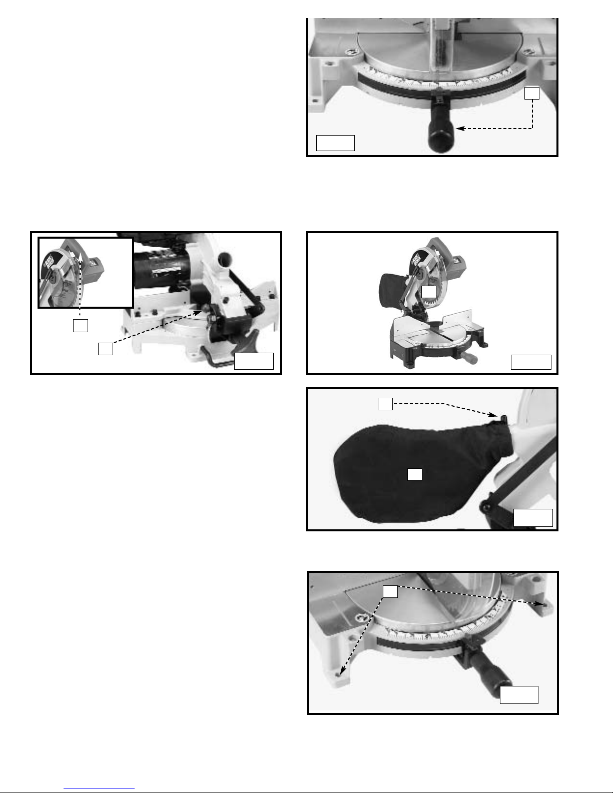
2. Rotate the table to the left until the index stop engages
with the 90° positive stop (Fig. 6). Tighten the table lock
handle (A).
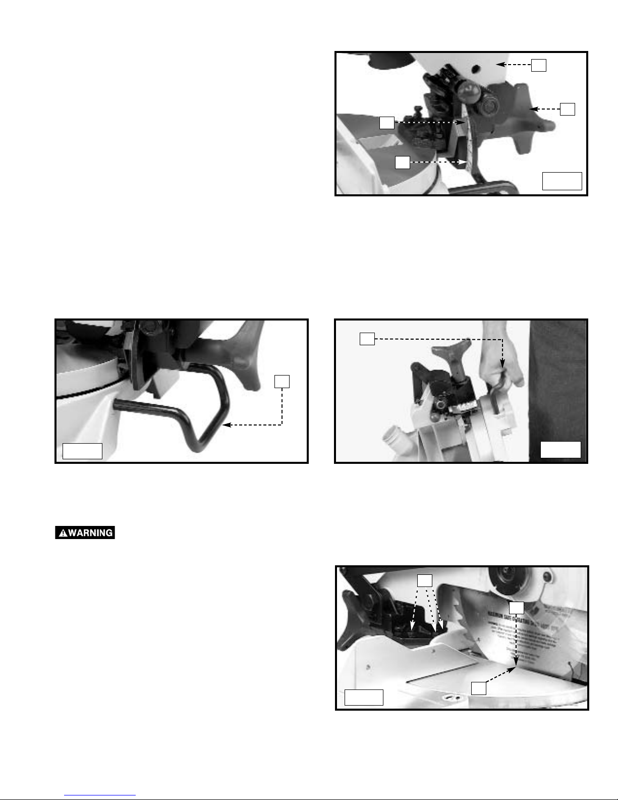
1. Push down on handle (A), Inset, Fig. 7. Pull out the cuttinghead lock knob (B).
2. Move the cuttinghead (C) to the up position (Fig. 8).
ATTACHING THE DUST BAG
Squeeze the spring clips (A) Fig. 9 of the dust bag (B) and clip
the dust bag (B) over the ribs of the dust chute.
MOVING CUTTINGHEAD TO THE UP POSITION
Fig. 6
A
Fig. 7
Fig. 8
A
B
C
Fig. 9
A
B
A
Fig. 10
Page 11
A turning saw blade can be dangerous. After completing cut, release switch trigger (A) Fig. 12, to activate
blade brake. Keep cuttinghead down until blade has come to a complete stop.
The torque developed during braking may loosen the arbor screw (E) Fig. 44. The arbor screw should be checked
periodically and tightened if necessary.
OPERATION
TABLE HAZARD AREA
The area inside the two red lines (A) Fig. 11
on the table is designated as a hazard zone. Never place
your hands inside this area while the machine is running.
STARTING AND STOPPING THE MITER SAW
To start the miter saw, depress the switch trigger (A) Fig. 12. To stop the miter saw, release the switch trigger.
This saw is equipped with an automatic electric blade brake. As soon as the switch trigger (A) Fig. 12, is released, the electric brake
is activated and stops the blade in seconds.
OPERATIONAL CONTROLS AND ADJUSTMENTS
Fig. 11
A
Fig. 12
A
Page 12
ADJUSTING THE POINTER
To transport the saw, always lock the cuttinghead in the down
position. Lower the cuttinghead (A) Fig. 17, and push the
cuttinghead lock knob (B) into the hole in the cutting arm until it
locks the cuttinghead.
IMPORTANT: Carrying the machine by the switch handle will
cause misalignment. Always lift the machine by the base or
by the carrying handle (See Fig. 20).
Your miter saw will cut any angle from a straight 90° cut to 47° right and left. Turn the lock handle (A) Fig. 13 counter-clockwise one
or two turns, depress the index lever (B), and move the control arm to the desired angle. Tighten the lock handle (A).
The miter saw is equipped with positive stops at the 0°, 22.5°, 31.62°, and 45° right and left positions. Loosen the lock handle (A)
Fig. 13, and move the control arm until the bottom of the index lever (B) engages into one of the positive stops, four of which are
shown at (C). Tighten the lock handle (A). To disengage the positive stop, depress the index lever (B).
A triangle indicator (D) Fig. 15 is provided on the miter scale at the 31.62° right and left miter positions for cutting crown moulding.
(Refer to the “CUTTING CROWN MOULDING” section of this manual).
IMPORTANT: Always tighten the lock handle (A) Fig. 14 before cutting.
POINTER AND SCALE
The pointer (E) Fig. 15 indicates the angle of cut. Each line on the scale (F) represents 1 degree. When you move the pointer from
one line to the next on the scale, you change the angle of cut by 1 degree.
ROTATING THE TABLE FOR MITER CUTTING
Fig. 13
Fig. 14
C
B
A
A
Fig. 15
F
D
E
To adjust the pointer (E) Fig. 16, loosen the screw (G), adjust the pointer (E), and tighten the screw.
E
G
Fig. 16
LOCKING THE CUTTINGHEAD IN THE DOWN POSITION
A
B
Fig. 17
Page 13
You can tilt the cuttinghead of your compound miter saw to cut
any bevel angle from a 90° straight cut off to a 45° left bevel
angle. Loosen the bevel lock handle (A) Fig. 18, tilt the cutting
arm (B) to the desired angle, and tighten the lock handle (A).
Positive stops are provided to rapidly position the saw blade at
90° and 45° to the table. Refer to the section of this manual
titled “ADJUSTING 90° AND 45° BEVEL STOPS.” The bevel
angle of the cuttinghead is determined by the position of the
pointer (C) Fig. 18 on the scale (D).
A triangle indicator is provided on the bevel scale at the 33.86°
bevel angle for cutting crown moulding. Refer to the
“CUTTING CROWN MOULDING” section of this manual.
A rear support bar (A) Fig. 19 is provided to prevent the machine from tipping to the rear when the cuttinghead returns to the up
position. For maximum support, pull the bar (A) out as far as possible.
You can also use the support bar (A) Fig. 20 to carry the machine.
TILTING THE CUTTINGHEAD FOR BEVEL CUTTING
C
B
A
D
Fig. 18
REAR SUPPORT/CARRYING HANDLE
A
Fig. 19
Fig. 20
A
ADJUSTING THE BLADE PARALLEL TO THE TABLE SLOT
1. Lower the cutting arm. The saw blade (A) Fig. 21 should be
parallel to the left edge (B) of the table opening.
2. To adjust, loosen the three bolts (C) Fig. 21 and move the
cutting arm until the blade is parallel with the left edge (B)
of the table opening and centered in the slot. Tighten the
three bolts (C).
DISCONNECT MACHINE FROM POWER SOURCE!
Fig. 21
C
B
A
Page 14
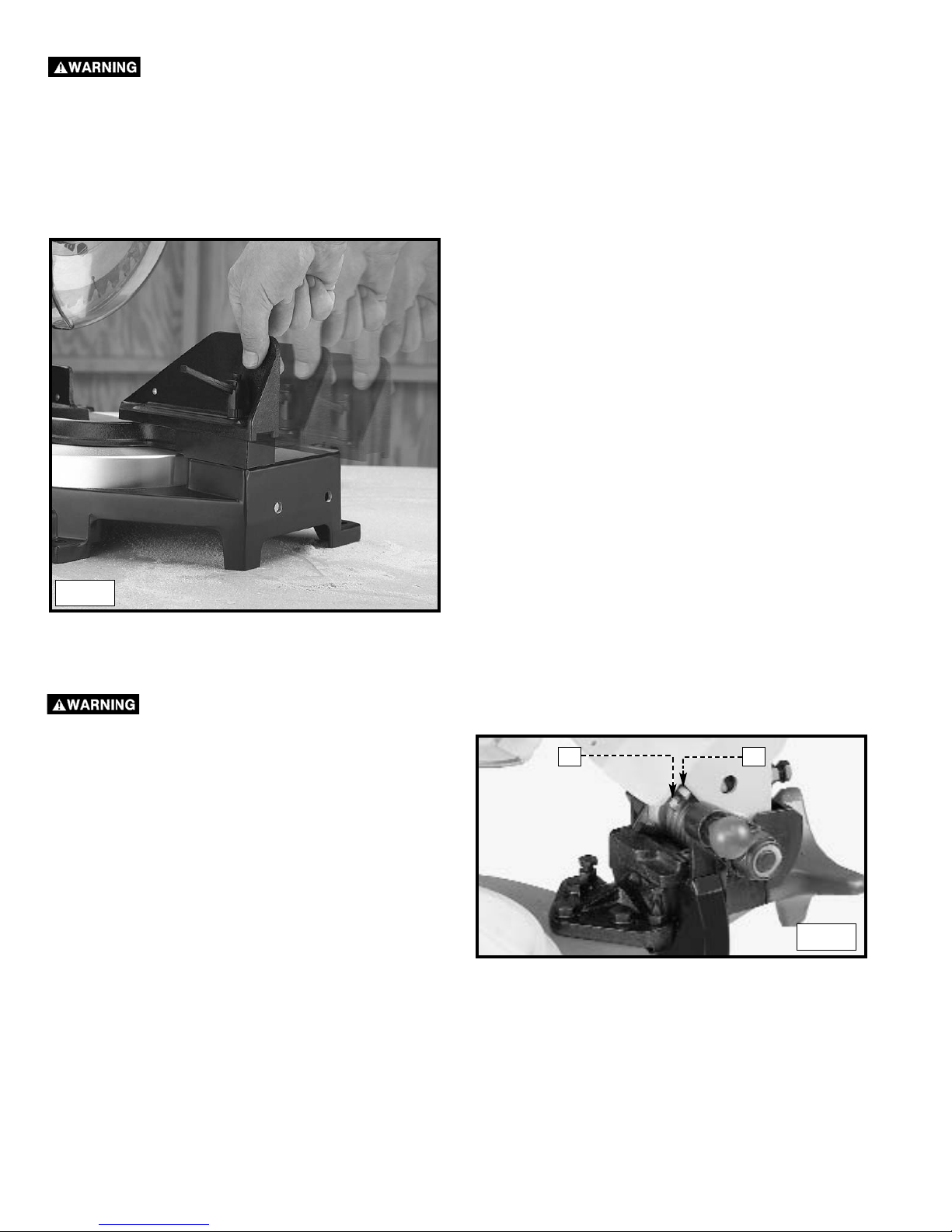
1. You can limit the downward travel of the saw blade to
prevent it from contacting any metal surfaces of the
machine. Make this adjustment by loosening the locknut
(A) Fig. 23 and turning the adjusting screw (B) in or out.
2. Lower the blade as far as possible. Rotate the blade by
hand to make certain the teeth do not contact any metal
surfaces.
3. Tighten the locknut (A)
Fig. 22
ADJUSTING THE DOWNWARD TRAVEL OF THE SAW BLADE
DISCONNECT MACHINE FROM POWER SOURCE!
Fig. 23
A
B
In order that the saw can bevel to a full 47 degrees left, the left side of the fence can be adjusted to the left to provide clearance. To
adjust the fence, loosen the plastic knob shown in Figure 22 and slide the fence to the left. Make a dry run with the saw turned off and
check for clearance. Adjust the fence to be as close to the blade as practical to provide maximum workpiece support, without
interfering with arm up & down movement. Tighten knob securely. When the bevel operations are complete, don’t forget to relocate the
fence to the right.
NOTE: The guide groove in the left side fence can become clogged with sawdust. If you notice that it is becoming clogged, use a stick
or some low pressure air to clear the guide groove.
FENCE ADJUSTMENT
DISCONNECT MACHINE FROM POWER SOURCE!
Page 15
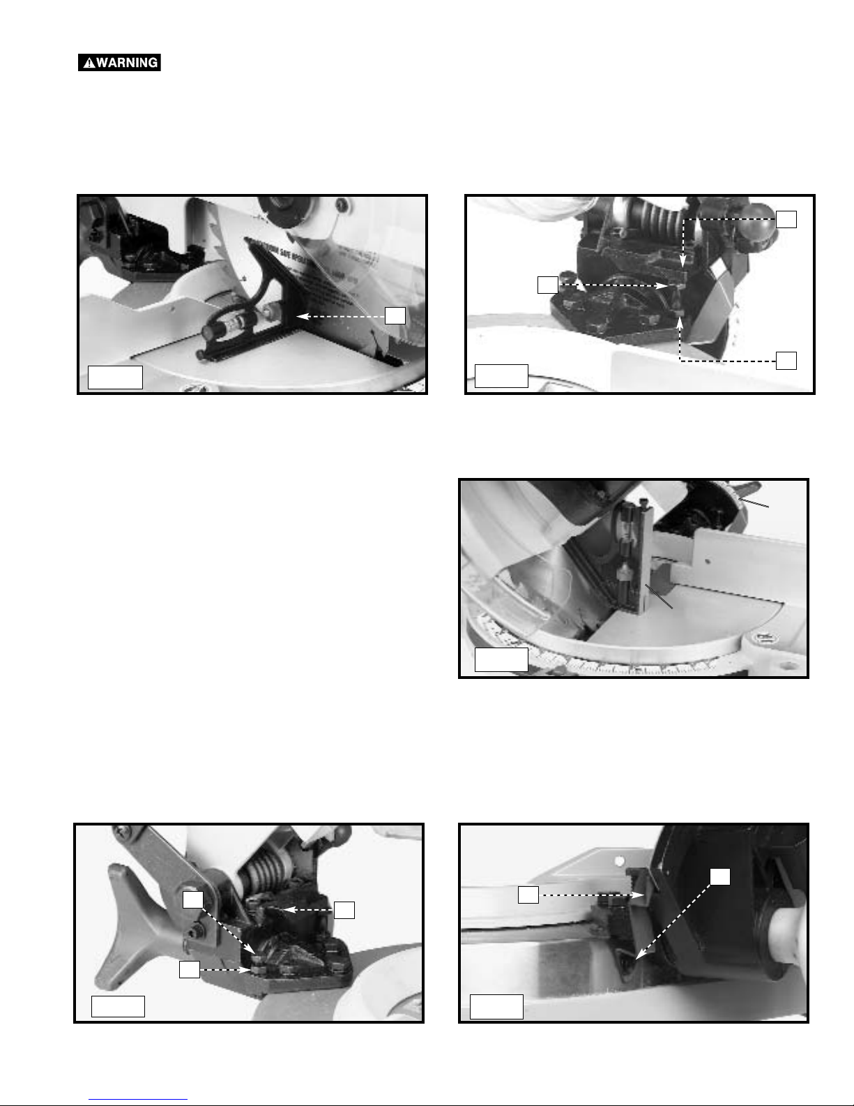
1. Loosen the bevel lock handle (A) Fig. 18 and move the cutting arm (B) Fig. 18 all the way to the right. Tighten the bevel lock
handle.
2. Place one end of a square (A) Fig. 24 on the table and the other end against the blade. Check to see if the blade is 90° to the
table (Fig. 24).
3. To adjust, loosen the locknut (B) Fig. 25, and turn the screw (C) until the head of the screw (C) contacts the casting (D) when
blade is 90° degrees to the table. Tighten the locknut (B).
4. Loosen the bevel lock handle. Move the cutting arm all the
way to the left bevel position and tighten the bevel lock
handle.
5. Use a combination square (A) Fig. 26 to see if the blade is
at 45° to the table.
6. To adjust, loosen the locknut (E) Fig. 27, and turn the screw (F) until it contacts the casting (G). Tighten the locknut (E).
7. Check to see that the bevel pointer (P) Fig. 28 is pointing to the 45° mark on the bevel scale (S) Fig. 26. To adjust the bevel
pointer (P) Fig. 28, loosen the screw (H) and adjust pointer (P). Tighten the screw (H) securely.
8. These positive stops enable you to rapidly position the blade at the 90° and 45° bevel angle to the table.
A
S
ADJUSTING 90° AND 45° BEVEL STOPS
DISCONNECT MACHINE FROM POWER SOURCE!
Fig. 24
Fig. 25
A
D
C
B
Fig. 26
Fig. 27
Fig. 28
E
G
F
P
H
Page 16
TYPICAL OPERATIONS AND HELPFUL HINTS
1. Before cutting, make certain that the cutting arm and table are at their correct settings and firmly locked in place.
2. Place the workpiece on the table and hold it firmly against the fence.
3. Keep your hands out of the “Hazard Zone”.
4. For best results, cut at a slow, even cutting rate.
5. Never attempt freehand cutting (wood that is not held firmly against the fence and table).
Holes are provided in the fence to attach an auxiliary fence (A) Fig. 30. This auxiliary fence is constructed of straight wood
approximately 1/2" thick by 3" high by 20" long.
MACHINE USE
AUXILIARY WOOD FENCE
When performing multiple or repetitive operations that result in small cut-off pieces (one inch or less), the
saw blade can catch the cut-off pieces and project them out of the machine or into the blade guard and housing, causing
damage or injury. To limit the risk, mount an auxiliary wood fence on your saw (Fig. 30).
NOTE: The auxiliary fence (A) is used ONLY with the saw blade in the 0° bevel position (90° to the table). When you bevel cut (blade
tilted), remove the auxiliary fence.
A
A
Fig. 30
The tension of the cuttinghead return spring was adjusted
at the factory so that the cuttinghead returns to the "up"
position after cutting.
To adjust the spring tension, loosen the locknut (A) Fig.
29 and turn the screw (B) (clockwise to increase or
counterclockwise to decrease the spring tension). After
adjustment, tighten the locknut (A).
ADJUSTING THE TENSION OF THE CUTTINGHEAD RETURN SPRING
DISCONNECT MACHINE FROM POWER SOURCE!
B
A
Fig. 29
Page 17
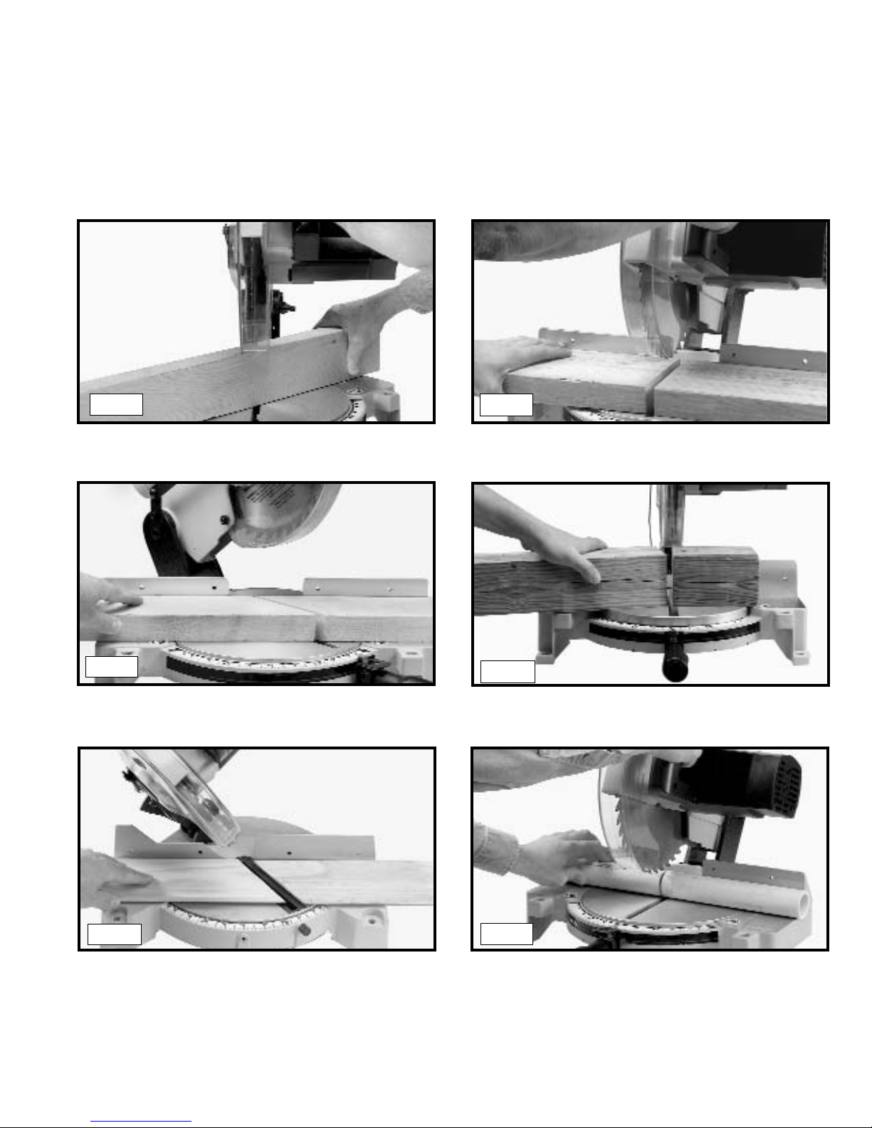
GENERAL CUTTING OPERATIONS
1. Your machine has the capacity to cut standard 2 x 4’s, lying flat or on edge, at the 45° right and left miter angles (Fig. A1 & A2).
2. A standard 2 x 6 can be cut in the 90° straight cut-off position in one pass (Fig. A3).
3. Cutting a standard 4 x 4 can be accomplished with one pass (Fig. A4).
4. This machine has the capacity to accurately cut crown mouldings and other bevel-type cuts (Fig. A5).
5. Cutting various sizes of plastic pipe is an easy job with this machine (Fig. A6). Hold pipe firmly against the fence. Use extra care
and secure pipe firmly when cutting angles into pipe.
A1 A2
A3
A4
A5
A6
Page 18
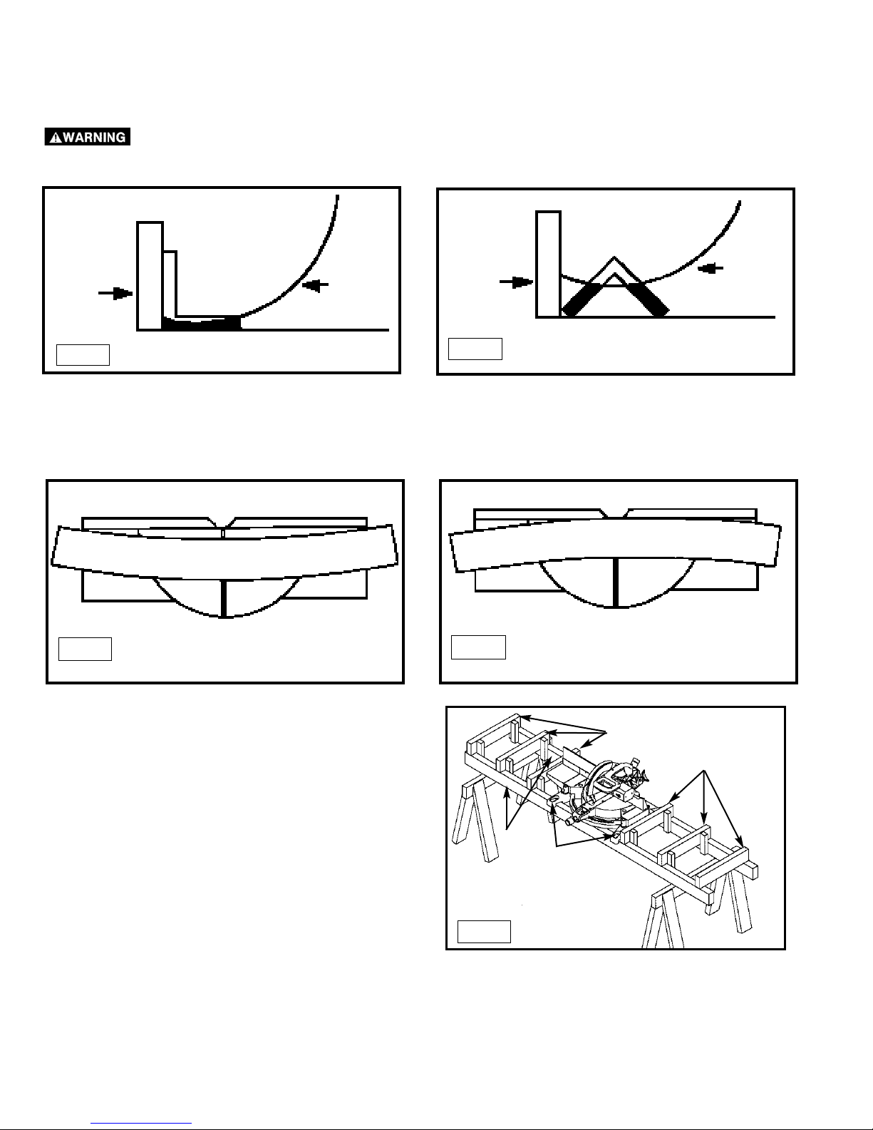
CUTTING BOWED MATERIAL
Check to see if your workpiece is bowed. If it is, make sure the material is positioned on the table as shown in Fig. 33.
If the material is positioned the wrong way, as shown in Fig. 34, the workpiece will pinch the blade near the completion of the cut.
RIGHT
WRONG
C
B
A
C
WORK SUPPORT EXTENSIONS
For support when cutting long pieces, a work support
extension can be constructed. Fig. 35 illustrates the miter saw
mounted to two standard 2 x 4’s (A). Fasten the four mounting
legs (two of which are shown at (B) Fig. 36 to the 2 x 4’s, using
four screws (not supplied) through the four holes in the
mounting legs. The length of the 2 x 4’s (A) can vary,
depending on the kind of work that will need to be cut.
NOTE: Ensure that the top of the support 2 x 4’s (C) are
level with the miter saw table.
This is critical because the distance from the top of the
2 x 4’s (A) to the miter saw table varies from saw to saw. In
most cases, standard 2 x 4’s (C) can used. If these are too
high, cut the 2 x 4s (C) to provide this height or use other
properly-sized wood.
CUTTING ALUMINUM
Aluminum extrusions such as used for making aluminum screens and storm windows can easily be cut with your compound miter
saw. When cutting aluminum extrusions, or other sections that can be cut with a saw blade and are within the capacity of the machine,
position the material so the blade is cutting through the smallest cross-section (Fig. 31). The wrong way to cut
aluminum angles is illustrated in Fig. 32. Be sure to apply a stick wax to the blade before cutting aluminum stock. This stick wax is
available at most industrial mill supply houses. The wax provides proper lubrication and keeps chips from adhering to the blade.
NEVER APPLY LUBRICANT TO THE BLADE WHILE THE MACHINE IS RUNNING.
FENCE
BLADE
WRONG
FENCE
BLADE
RIGHT
Fig. 32
Fig. 31
Fig. 33
Fig. 34
Fig. 35
Page 19
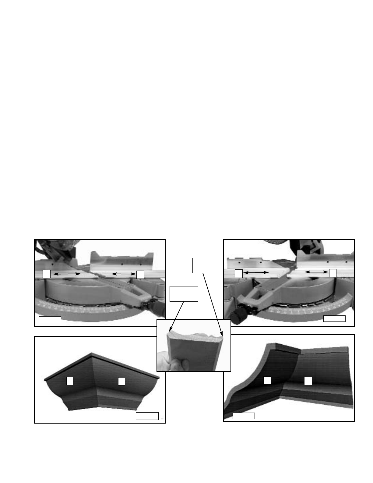
CUTTING CROWN MOULDING
One of the many features of the saw is the ease of cutting crown moulding. The following is an example of cutting both inside and
outside corners on 52°/38° wall angle crown moulding.
1. Move the table to the 31.62° right miter position and lock the table in position. NOTE: A positive stop is provided to find this angle
quickly.
2. Tilt the saw blade to the 33.86° left bevel position and tighten bevel lock handle. NOTE: A triangle indicator is provided on the
bevel scale to find this angle quickly.
3. Place the crown moulding on the table with the CEILING EDGE of the moulding against the fence, and make the cut, as shown
in Fig. 36.
NOTE: The piece of crown moulding used for the outside corner will always be on the right hand side of the blade, as shown at (A)
Fig. 36. The piece of crown moulding used for the inside corner will always be on the left hand side of the blade, as shown at (B)
Fig. 36.
4. To make the matching halves of the inside and outside corners, rotate the table to the 31.62° left miter position.
NOTE: A positive stop is provided to find this angle quickly. The saw blade is already tilted to the 33.86° left bevel position from the
previous cut.
5. Place the crown moulding on the table with the WALL EDGE of the crown moulding against the fence and make the cut. Again,
the piece of crown moulding used for the outside corner will always be on the right side of the blade, as shown at (C) Fig. 37. The
piece of crown moulding used for the inside corner will always be on the left side of the blade, as shown at (D) Fig. 37.
6. Fig. 38 illustrates the two outside corner pieces; (A) being the piece cut at (A) Fig. 36 and (C) being the piece cut at (C) Fig. 37.
7. Fig. 39 illustrates the two inside corner pieces; (B) being the piece cut at (B) Fig. 36, and (D) being the piece cut at (D) Fig. 37.
45-45 CROWN MOULDING
NOTE: If you are cutting crown moulding that is 45°-45°, follow the same procedure above, with the exception that the bevel position
will always be at 30° and the miter position will be 35-1/4° to the right or left.
Fig. 37
Fig. 36
Fig. 38
Fig. 39
D
C
B
A
C
A
B
D
WALL
EDGE
CEILING
EDGE
Page 20
MAINTENANCE
CHANGING THE BLADE
Use only cross-cutting saw blades.
When using carbide-tipped blades, do not
use blades with deep gullets as they can
deflect and contact the guard.
Use only 10" diameter saw blades which are
rated for 5200 rpm or higher and have 5/8"
diameter arbor holes.
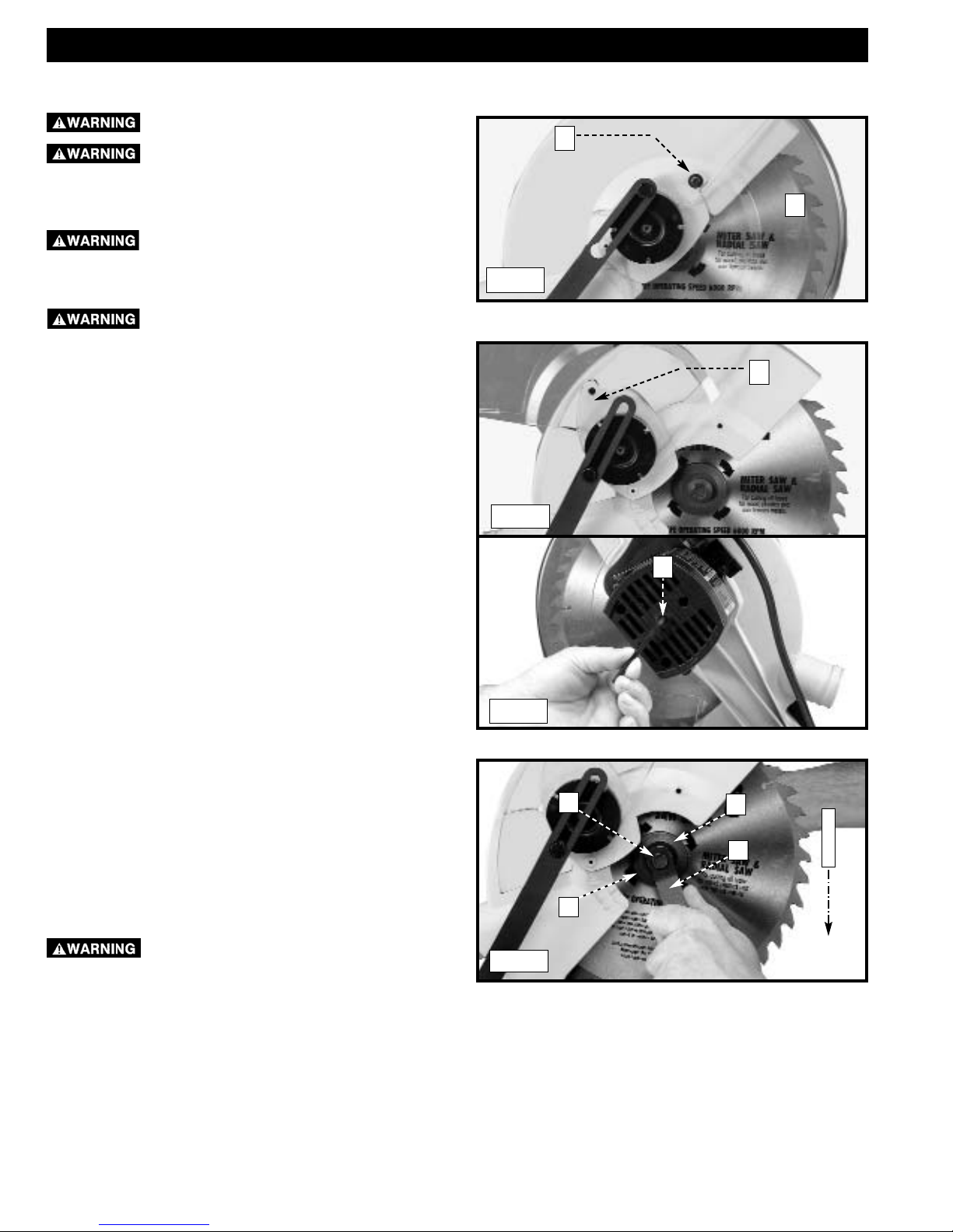
1. Remove screw (A) Fig. 40 and rotate cover (B) to the rear
(Fig. 41).
2. To remove the saw blade, insert the hex wrench (C)
Fig. 42 into the hex hole located on the rear end of the
motor shaft to keep the shaft from turning.
3. Use a wrench (G) Fig. 43 to loosen the arbor screw (E) by
turning it clockwise.
4. Remove the arbor screw (E) Fig. 43, the outside blade
flange (F), and the saw blade from the saw arbor.
5. Attach the new saw blade
making certain that the teeth of
the saw blade are pointing down (Fig. 43). Place the
outside blade flange (F) on the arbor, and attach the arbor
screw (E) by turning it counter-clockwise using the wrench
(G) Fig. 43. At the same time, use the hex wrench (C) Fig.
42 to keep the arbor from turning.
6. Rotate the cover back to the front and replace the screw
that was removed in STEP 1.
DISCONNECT MACHINE FROM POWER SOURCE!
Remove wrenches (C) Fig. 42 and (G) Fig. 43
before starting machine.
Fig. 40
Fig. 41
Fig. 42
Fig. 43
A
B
B
C
E
B
G
T
E
E
T
H
F
Page 21
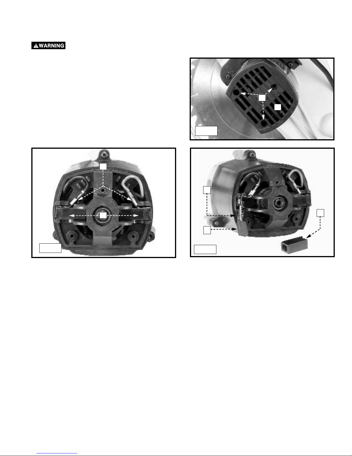
1. Remove three screws (A) Fig. 44 and remove the motor
cover (B).
2. The brushes are located in the two holders (C) Fig. 45.
Remove spade type terminal connector (D) and pull out
brush holders (C).
3. Fig. 46 illustrates one of the brushes (E) removed from the
holder (C). When the carbon on either brush (E) is worn to
3/16" in length or if either spring (F) or shunt wire is
burned or damaged in any way, replace both brushes. If
the brushes are found to be serviceable after re-moving,
reinstall them in the same position.
Brush life varies. It depends on the load on the motor. Check the brushes after the first 50 hours of use for a new machine or after
a new set of brushes has been installed. After the first check, examine them after about 10 hours of use until a replacement is
necessary. To inspect the brushes:
Use only mild soap and damp cloth to clean the tool. Never let any liquid get inside the tool; never immerse any part of the tool into a
liquid.
IMPORTANT
To assure product SAFETY and RELIABILITY, repairs, maintenance and adjustment (including brush inspection and replacement)
should be performed by authorized service centers or other qualified service organizations, always using identical replacement parts.
B
A
Fig. 44
Fig. 45
Fig. 46
D
C
C
E
F
BRUSH INSPECTION AND REPLACEMENT
DISCONNECT MACHINE FROM POWER SOURCE!
Page 22

BE SURE TO FOLLOW SAFETY RULES AND INSTRUCTIONS
TROUBLE! SAW WILL NOT START
WHAT’S WRONG? WHAT TO DO…
1.Saw not plugged in. 1.Plug in saw.
2.Fuse blown or circuit breaker tripped. 2.Replace fuse or reset
circuit breaker.
3.Cord damaged. 3.Have cord replaced by
authorized service center.
4.Brushes worn out. 4.Have brushes replaced
by authorized service center.
TROUBLE! SAW MAKES UNSATISFACTORY CUTS
WHAT’S WRONG? WHAT TO DO…
1.Dull blade. 1.Replace blade.
2.Blade mounted backwards. 2.Turn blade around.
3.Gum or pitch on blade. 3.Remove blade and
clean with turpentine.
4.Incorrect blade for work being done. 4.Change the blade.
TROUBLE! BLADE DOES NOT COME UP TO SPEED
WHAT’S WRONG? WHAT TO DO…
1.Extension cord too light or too long. 1.Replace with adequate
size cord.
2.Low house current. 2.Contact your electric
company.
TROUBLE! MACHINE VIBRATES EXCESSIVELY
WHAT’S WRONG? WHAT TO DO…
1.Saw not mounted securely. 1.Tighten all mounting
hardware.
2.Stand or bench on uneven floor. 2.Reposition on flat level
surface.
3.Damaged saw blade. 3.Replace blade.
TROUBLE! DOES NOT MAKE ACCURATE MITER CUTS
WHAT’S WRONG? WHAT TO DO…
1.Miter scale not adjusted correctly. 1.Check and adjust.
2.Blade is not square to fence. 2.Check and adjust.
3.Blade is not perpendicular to table. 3.Check and adjust fence.
4.Workpiece moving. 4.Clamp workpiece to
fence or glue 120 grit
sandpaper to fence with
rubber cement.
TROUBLE! MATERIAL PINCHES BLADE
WHAT’S WRONG? WHAT TO DO…
1.Cutting bowed material. 1.Position bowed material
as shown in Figure 35.
Service Information
Black & Decker offers a full network of company-owned and authorized service locations throughout North America. All Black & Decker Service Centers
are staffed with trained personnel to provide customers with efficient and reliable power tool service.
Whether you need technical advice, repair, or genuine factory replacement parts, contact the Black & Decker location nearest you.
To find your local service location, refer to the yellow page directory under "Tools—Electric" or call: 1-800-54-HOW TO (544-6986).
Accessories
Recommended accessories for use with your saw are available from your local dealer or authorized service center. If you need
assistance regarding accessories, please call: 1-800-544-6986. WARNING: The use of any non-recommended accessory may be
hazardous.
Full Two-Year Home Use Warranty
Black & Decker (U.S.) Inc. warrants this product for two years against any defects in material or workmanship. The defective product will be replaced or
repaired at no charge in either of two ways:
The first, which will result in exchanges only, is to return the product to the retailer from whom it was purchased (provided that the store is a participating
retailer). Returns should be made within the time period of the retailer’s policy for exchanges (usually 30 to 90 days after the sale). Proof of purchase
may be required. Please check with the retailer for their specific return policy regarding returns that are beyond the time set for exchanges.
The second option is to take or send the product (prepaid) to a Black & Decker owned or authorized Service Center for repair or replacement at our
option. Proof of purchase may be required. Black & Decker owned and authorized service centers are listed under "Tools-Electric" in the yellow pages of
the phone directory.
This warranty does not apply to accessories. This warranty gives you specific legal rights and you may have other rights which vary from state to state.
Should you have any questions, contact the manager of your nearest Black & Decker Service Center.
This product is not intended for commercial use.
FREE WARNING LABEL REPLACEMENT: If your warning labels become illegible or are missing, call 1-800-544-6986 for a free replacement.
Black & Decker (U.S.) Inc.,
701 E. Joppa Rd.
Towson, MD 21286 U.S.A.
See ‘Tools-Electric’
– Yellow Pages –
for Service & Sales
TROUBLESHOOTING
Page 23

AVANT DE RETOURNER CE PRODUIT POUR QUELQUE
RAISON QUI SOIT, VEUILLEZ APPELER AU
1-800-54-HOW-TO (544-6986)
MODE D’EMPLOI
SSSSCCCCIIIIEEEE ÀÀÀÀ OOOONNNNGGGGLLLLEEEETTTTSSSS MMMMIIIIXXXXTTTTEEEESSSS DDDDEEEE 11110000 PPPPOOOO ((((222255554444 MMMMMMMM))
))
BBBBDDDDMMMMSSSS1111000000
00
CONSERVER CE MODE D’EMPLOI POUR UN
USAGE ULTÉRIEUR.
Page 24

TABLE DES MATIÈRES
DIRECTIVES DE SÉCURITÉ IMPORTANTES . . . . . . . . . . . . . . . . . . . . . . . . . . . . . . . . . . . . . . . . . . . . . . . . . . . . .24
LIGNES DIRECTRICES EN MATIÈRE DE SÉCURITÉ . . . . . . . . . . . . . . . . . . . . . . . . . . . . . . . . . . . . . . . . . . . . . .25
RÈGLES GÉNÉRALES DE SÉCURITÉ . . . . . . . . . . . . . . . . . . . . . . . . . . . . . . . . . . . . . . . . . . . . . . . . . . . . . . . . . . .26
RÈGLES DE SÉCURITÉ SPÉCIFIQUES SUPPLÉMENTAIRES . . . . . . . . . . . . . . . . . . . . . . . . . . . . . . . . . . . . . .27
CONTENU DU CARTON . . . . . . . . . . . . . . . . . . . . . . . . . . . . . . . . . . . . . . . . . . . . . . . . . . . . . . . . . . . . . . . . . . . . . .29
DESCRIPTION FONCTIONNELLE . . . . . . . . . . . . . . . . . . . . . . . . . . . . . . . . . . . . . . . . . . . . . . . . . . . . . . . . . . . . .30
ASSEMBLAGE . . . . . . . . . . . . . . . . . . . . . . . . . . . . . . . . . . . . . . . . . . . . . . . . . . . . . . . . . . . . . . . . . . . . . . . . . . . . .31
FONCTIONNEMENT . . . . . . . . . . . . . . . . . . . . . . . . . . . . . . . . . . . . . . . . . . . . . . . . . . . . . . . . . . . . . . . . . . . . . . . .33
ENTRETIEN . . . . . . . . . . . . . . . . . . . . . . . . . . . . . . . . . . . . . . . . . . . . . . . . . . . . . . . . . . . . . . . . . . . . . . . . . . . . . . . .42
RÉPARATION . . . . . . . . . . . . . . . . . . . . . . . . . . . . . . . . . . . . . . . . . . . . . . . . . . . . . . . . . . . . . . . . . . . . . . . . . . . . . .43
DÉPANNAGE . . . . . . . . . . . . . . . . . . . . . . . . . . . . . . . . . . . . . . . . . . . . . . . . . . . . . . . . . . . . . . . . . . . . . . . . . . . . . .44
ACCESSOIRES . . . . . . . . . . . . . . . . . . . . . . . . . . . . . . . . . . . . . . . . . . . . . . . . . . . . . . . . . . . . . . . . . . . . . . . . . . . .44
GARANTIE . . . . . . . . . . . . . . . . . . . . . . . . . . . . . . . . . . . . . . . . . . . . . . . . . . . . . . . . . . . . . . . . . . . . . . . . . . . . . . . . .44
DIRECTIVES DE SÉCURITÉ IMPORTANTES
Lisez et comprenez tous les avertissements et directives d’utilisation avant d’utiliser un outil ou un
équipement. Lorsque vous utilisez des outils ou un équipement, des précautions de base en matière de sécurité
doivent être suivies afin de réduire le risque de blessure personnelle. Un fonctionnement, un entretien ou une
modification inappropriés des outils ou de l’équipement pourraient résulter en de graves blessures ou en des
dommages à la propriété. Certaines applications sont conçues pour des outils et de l’équipement spécifiques. Black
& Decker recommande fortement NE PAS modifier ce produit ou de NE PAS l’utiliser pour une application autre que
celle pour laquelle il a été conçu.
CONSERVER CES DIRECTIVES!
Page 25

certaines poussières produites par les activités de ponçage, de sciage, de meulage, de perçage et autres
activités de construction peuvent contenir des produits chimiques pouvant causer le cancer, des anomalies
congénitales ou d'autres problèmes liés aux fonctions reproductrices. Voici quelques exemples de ces produits
chimiques :
•
le plomb contenu dans les peintures à base de plomb;
•
la silice cristalline de la brique, du ciment et d'autres produits de maçonnerie ;
•
l'arsenic et le chrome provenant du bois traité chimiquement (arséniate de cuivre et de chrome).
Les risques reliés à l'exposition à ces poussières varient selon la fréquence à laquelle l'utilisateur travaille avec ce type de matériaux. Afin
de réduire votre exposition à ces produits chimiques : travailler dans un endroit bien ventilé et porter un équipement de sécurité
approuvé comme un masque anti-poussières conçu spécialement pour filtrer les particules microscopiques.
•
Éviter le contact prolongé avec les poussières produites par les activités de ponçage, sciage, meulage, perçage et autres activités de
construction. Porter des vêtements de protection et laver les parties du corps exposées avec une solution d'eau et de savon. Le fait de
laisser la poussière pénétrer dans la bouche et les yeux ou de la laisser reposer sur la peau, peut promouvoir l'absorption de produits
chimiques nocifs.
l'utilisation de cet outil peut produire et/ou disperser de la poussière, ce qui peut causer des problèmes
respiratoires graves et permanents ou d'autres problèmes médicaux. Toujours porter un appareil respiratoire approuvé par la
NIOSH/OSHA pour se protéger de la poussière. Diriger les particules loin du visage et du corps.
porter un dispositif de protection anti-bruit pendant l’utilisation de l’outil. Dans certaines conditions et selon la
durée d’utilisation, le bruit causé par ce produit peut contribuer à une perte auditive.
Pour plus de commodité et de sécurité, les étiquettes de sécurité suivantes sont apposées sur votre scie à onglet.
SUR LE BOÎTIER DU MOTEUR :
AVERTISSEMENT : POUR SA PROPRE SÉCURITÉ, LIRE LE MODE D’EMPLOI AVANT D’UTILISER LA SCIE. EN CAS DE RÉPARATION,
UTILISER UNIQUEMENT DES PIÈCES DE RECHANGE IDENTIQUES. TOUJOURS PORTER UNE PROTECTION OCULAIRE.
SUR LE GUIDE :
FIXER LES PETITES PIÈCES AVANT DE LES COUPER. VOIR LE MANUEL.
SUR LE P
ARE-MAIN : DANGER – RESTER À L’ÉCART DE LA LAME.
SUR LA PLAQUE DU P
ARE-MAIN : « BIEN FIXER LE SUPPORT AVEC LES DEUX VIS AVANT D’UTILISER L’OUTIL. »
SUR LA T
ABLE (2 ENDROITS)
TOUJOURS BIEN SERRER LES POIGNÉES DE RÉGLAGE AVANT
UTILISATION. GARDER LES MAINS À 15 CM (6 PO) DE LA TRAJECTOIRE DE LA LAME DE LA SCIE. NE JAMAIS EFFECTUER AUCUNE
OPÉRATION À MAIN LEVÉE. NE JAMAIS PASSER LES BRAS DEVANT LA LAME. IL SUFFIT DE RÉFLÉCHIR! DES ACCIDENTS PEUVENT
ÊTRE ÉVITÉS. NE PAS UTILISER LA SCIE SANS QUE LES PARE-MAINS NE SOIENT EN PLACE. NE JAMAIS PASSER LES MAINS À
L’ARRIÈRE DE LA LAME DE LA SCIE. TOUJOURS PORTER UNE PROTECTION OCULAIRE. METTRE L’APPAREIL SOUS TENSION ET
ATTENDRE L’ARRÊT DE LA LAME AVANT DE RÉPARER, RÉGLER L’OUTIL, OU DE DÉPLACER LES MAINS.
PROPOSITION 65 DE LA CALIFORNIE
LIGNES DIRECTRICES EN MATIÈRE DE SÉCURITÉ
- DÉFINITIONS
Il est important que vous lisiez et compreniez ce mode d’emploi. Les informations qu’il contient concernent VOTRE SÉCURITÉ et
visent à ÉVITER TOUT PROBLÈME. Les symboles ci-dessous servent à vous aider à reconnaître cette information.
indique une situation dangereuse imminente qui, si elle n’est pas évitée, causera la mort ou des graves blessures.
indique une situation potentiellement dangereuse qui, si elle n’est pas évitée, pourrait causer la mort ou de
graves blessures.
indique une situation potentiellement dangereuse qui, si elle n’est pas évitée, pourrait causer des blessures
mineures ou modérées.
Le terme utilisé sans le symbole d’alerte à la sécurité indique une situation potentiellement dangereuse qui, si elle
n’est pas évitée, peut résulter en des dommages à la propriété.
Page 26

RÈGLES GÉNÉRALES DE SÉCURITÉ
1. POUR SA PROPRE SÉCURITÉ,
LIRE LE MODE D’EMPLOI AVANT D’UTILISER
L’OUTIL. En apprenant comment utiliser cet outil, les
restrictions, et les risques qui lui sont propres, vous
réduirez grandement la possibilité d'accidents et de
blessures.
2. UTILISER UN ÉQUIPEMENT DE SÉCURITÉ
HOMOLOGUÉ. Votre protection oculaire doit être
conforme aux normes ANSI Z87.1, vos protecteurs
auditifs aux normes ANSI S3.19, et votre masque
antipoussières aux normes homologuées MSHA/NIOSH.
Les éclats de bois, débris en suspension dans l’air, et
poussières peuvent provoquer des irritations, blessures
et/ou maladies.
3. S’HABILLER DE MANIÈRE APPROPRIÉE. Ne pas
porter de cravate, gants, ou vêtements amples. Retirer
montre, bagues, et autres bijoux. Relever les manches.
Les vêtements ou bijoux coincés dans les pièces mobiles
peuvent causer des blessures.
4. NE PAS UTILISER CET OUTIL DANS UN
ENVIRONNEMENT DANGEREUX. L’utilisation d’outils
électriques dans un endroit humide ou mouillé ou sous la
pluie peut provoquer un choc électrique ou une
électrocution. Tenir la zone de travail bien éclairée pour
éviter de trébucher ou de mettre vos bras, mains et
doigts en danger.
5. CONSERVER TOUS LES OUTILS ET MACHINES DANS
LE MEILLEUR ÉTAT POSSIBLE. S’assurer que vos outils
sont aiguisés et propres afin d’optimiser sécurité et
performance. Suivre les consignes de graissage et de
changement d’accessoires. Les outils et machines mal
entretenus peuvent s'endommager davantage et/ou
provoquer des blessures.
6. VÉRIFIER QUE LES PIÈCES NE SONT PAS
ENDOMMAGÉES. Avant d’utiliser la machine, vérifiez
qu'aucune pièce n'est endommagée. Vérifier l’alignement
des pièces mobiles, la présence de grippage des pièces
mobiles, de rupture de pièces et tout autre problème
pouvant nuire au fonctionnement de l’outil. Un pare-main
(ou tout autre pièce) endommagé doit être réparé et
remplacé adéquatement. Les pièces endommagées
peuvent contribuer à endommager davantage la machine
et/ou provoquer des blessures.
7. GARDER PROPRE LA ZONE DE TRAVAIL. Les zones et
établis encombrés sont souvent des causes d’accidents.
8. ÉLOIGNER LES ENFANTS ET LES VISITEURS. Votre
atelier représente un environnement potentiellement
dangereux. Les enfants et visiteurs peuvent être blessés.
9. RÉDUIRE LE RISQUE DE DÉMARRAGE ACCIDENTEL.
Assurez-vous que l’interrupteur se trouve sur la position
d’arrêt avant de brancher le cordon d’alimentation. En
cas de panne de courant, mettez l’interrupteur sur la
position d’arrêt. Un démarrage accidentel peut provoquer
des blessures.
10. UTILISER LE DISPOSITIF DE PROTECTION. Vérifiez
que toutes les protections sont en place, fixées, et
qu’elles fonctionnent correctement afin d'éviter toute
blessure.
11. RETIRER LES CLÉS ET LES CLÉS DE RÉGLAGE
AVANT DE DÉMARRER LA MACHINE. Des outils,
chutes, et autres débris peuvent être projetés à grande
vitesse, provoquant des blessures.
12. UTILISER L’OUTIL APPROPRIÉ. Ne pas forcer un outil
ou un accessoire à effectuer un travail pour lequel il n’a
pas été conçu. Dans le cas contraire, l'outil peut être
endommagé et/ou vous pourriez vous blesser.
13. UTILISER LES ACCESSOIRES RECOMMANDÉS.
L’utilisation d’accessoires qui n’ont pas été
recommandés par Black & Decker est susceptible
d’endommager la machine ou de blesser l'utilisateur.
14. UTILISER LA RALLONGE ÉLECTRIQUE APPROPRIÉE.
S’assurer que la rallonge est en bon état. Lorsque qu’une
rallonge électrique est utilisée, s’assurer d’en utiliser une
de calibre suffisamment élevé pour assurer le transport
du courant nécessaire au fonctionnement de votre
appareil. Un cordon de calibre inférieur causera une
chute de tension de ligne et donc une perte de puissance
et une surchauffe. Reportez-vous au tableau des
rallonges électriques pour connaître le calibre approprié à
utiliser selon la longueur de la rallonge et l’intensité
nominale de la plaque signalétique. En cas de doute,
utiliser le calibre suivant le plus gros. Plus le numéro de
calibre est petit, plus le cordon est lourd.
15. FIXER LA PIÈCE. Utiliser des fixations ou un étau
lorsque la pièce ne peut pas être fixée manuellement sur
la table et contre le guide, ou lorsque votre main se
trouve dangereusement proche de la lame (à moins de 15
cm (6 po)).
16. NE PAS FORCER LA PIÈCE SUR LA MACHINE. Dans le
cas contraire, l'outil peut être endommagé et/ou vous
pourriez vous blesser.
17. NE PAS TROP TENDRE LES BRAS. Une perte
d’équilibre peut vous faire tomber dans une machine en
fonctionnement, et vous pourriez vous blesser.
18. NE JAMAIS SE TENIR DEBOUT SUR LA MACHINE. Si
l’outil bascule, ou si vous touchez accidentellement l’outil
de coupe, vous pourriez vous blesser.
19. NE JAMAIS LAISSER LA MACHINE FONCTIONNER
SANS SURVEILLANCE. ÉTEINDRE L’APPAREIL. Ne
pas laisser la machine tant qu’elle n’est pas
complètement arrêtée. Un enfant ou un visiteur pourrait
être blessé.
20. ÉTEIGNEZ L’APPAREIL ET DÉBRANCHEZ-LE DE LA
SOURCE D’ALIMENTATION AVANT de poser ou de
retirer tout accessoire, avant d'ajuster ou de modifier les
réglages, ou lorsque vous effectuez une réparation. Un
démarrage accidentel peut provoquer des blessures.
21. S’ASSURER QUE L’ATELIER NE PRÉSENTE PAS DE
DANGER POUR LES ENFANTS EN UTILISANT DES
CADENAS, DES INTERRUPTEURS PRINCIPAUX, OU
EN RETIRANT LES CLÉS DE DÉMARRAGE. En
démarrant accidentellement une machine, un enfant ou
un visiteur pourrait se blesser.
22. ÊTRE VIGILANT, SURVEILLER LE TRAVAIL
EFFECTUÉ, ET FAIRE PREUVE DE JUGEMENT. NE
PAS UTILISER LA MACHINE EN CAS DE FATIGUE OU
SOUS L’INFLUENCE DE DROGUES, D'ALCOOL, OU
DE MÉDICAMENTS. Un moment d’inattention, lorsque
vous utilisez un outil électrique, peut entraîner des
blessures.
23. LA POUSSIÈRE PRODUITE par certains bois et produits
en bois peut nuire à votre santé. Utilisez toujours les
machines dans un endroit bien aéré, et veillez à le
dépoussiérer correctement. Utilisez des systèmes de
dépoussiérage lorsque c’est possible.
LIRE ATTENTIVEMENT TOUTES LES MISES EN GARDE ET DIRECTIVES D’UTILISATION
AVANT D'UTILISER CET ÉQUIPEMENT. À défaut de suivre les directives sous-mentionnées,
un choc électrique, un incendie, des dommages ou une blessure corporelle grave
pourraient survenir.
DIRECTIVES DE SÉCURITÉ IMPORTANTES
Page 27

1. NE FAITES PAS FONCTIONNER CETTE MACHINE avant
qu’elle ne soit entièrement assemblée et installée
conformément à ces directives. Une machine mal
assemblée peut provoquer des blessures graves.
2. DEMANDEZ CONSEIL à une autre personne qualifiée si
vous ne maîtrisez pas assez l'utilisation de cette machine.
3. SUIVRE TOUS LES CODES DE CÂBLAGE et les
connexions électriques recommandées afin d’éviter tout
choc électrique ou électrocution.
4. FIXER LA MACHINE SUR UNE SURFACE DE SUPPORT.
Les vibrations sont susceptibles de faire glisser, « marcher
», ou basculer la machine, ce qui peut provoquer des
blessures graves.
5. UTILISER SEULEMENT DES LAMES POUR COUPES
TRANSVERSALES. N’utilisez que des angles de coupe de
zéro degré ou négatifs lorsque vous utilisez des lames à
pointes carburées. N’utilisez pas des lames à dents très
espacées. Celles-ci peuvent entrer en contact et faire dévier
le pare-main, et peuvent endommager la machine et/ou
provoquer des blessures graves.
6. UTILISER SEULEMENT DES LAMES DE DIMENSION ET
DE TYPE APPROPRIÉS prévues pour cet outil, pour éviter
des dommages à la machine et/ou des blessures graves.
7. UTILISER UNE LAME AIGUISÉE. Vérifiez que la lame
fonctionne bien dans l'axe et qu'elle ne vibre pas. Une lame
émoussée ou une lame qui vibre peut endommager la
machine et/ou provoquer des blessures graves.
8. INSPECTER LA LAME À LA RECHERCHE DE
CRAQUELURES ou autre dommage avant utilisation. Une
lame craquelée ou endommagée peut se détacher et des
fragments peuvent être projetés à grande vitesse, ce qui
peut provoquer des blessures graves. Remplacez les lames
craquelées ou endommagées immédiatement.
9. NETTOYER LA LAME ET LES BRIDES DE LA LAME
avant utilisation. Nettoyer la lame et les brides vous permet
de vérifier que la lame ou les brides ne sont pas
endommagées. Une lame ou une bride craquelée ou
endommagée peut se détacher et des fragments peuvent
être projetés à grande vitesse, ce qui peut provoquer des
blessures graves.
10. UTILISER UNIQUEMENT DES BRIDES DE LAME prévues
pour cet outil afin d'éviter d'endommager la machine et/ou
de provoquer des blessures graves.
11. S’ASSURER QUE L’ESPACE DE TRAVAIL NE CONTIENT
AUCUN LIQUIDE INFLAMMABLE ou de gaz avant
utilisation. Des étincelles peuvent se produire, qui
enflammeraient les liquides et provoqueraient un incendie
ou une explosion.
12. DÉGAGER LES ÉVENTS de toute saleté ou copeau. Des
évents obstrués peuvent provoquer la surchauffe de la
machine, ce qui l’endommagerait et provoquerait peut-être
un court-circuit qui pourrait engendrer des blessures
graves.
13. SERRER FERMEMENT LA POIGNÉE DE FIXATION À LA
TABLE et autres brides de fixation avant utilisation. Si les
brides sont lâches, des pièces ou encore l'ouvrage peuvent
être projetés à grande vitesse.
14. NE JAMAIS DÉMARRER L’OUTIL avec la lame contre
l'ouvrage. L’ouvrage pourrait être projeté, provoquant des
blessures graves.
15. TENIR LES BRAS, LES MAINS, et les doigts éloignés de
la lame afin d'éviter des coupures graves. Fixez toutes les
pièces à cause desquelles vous pourriez déplacer vos
mains dans la « Zone à risque de la table » (délimitée par
les lignes rouges).
16. LORS DE LA COUPE AVEC UNE SCIE COULISSANTE À
ONGLETS MIXTES, POUSSEZ LA SCIE VERS L'AVANT
(EN L’ÉLOIGNANT DE VOUS) et vers le guide. Si vous
ramenez la scie vers vous, celle-ci pourrait se soulever et
vous percuter.
17. LORS DE L’UTILISATION D’UNE SCIE COULISSANTE À
ONGLETS, VERROUILLER LE MÉCANISME COULISSANT
EN PLACE. Si le mécanisme coulissant n’est pas verrouillé,
la scie peut se retourner et vous percuter.
18. LAISSER LE MOTEUR atteindre son plein régime avant
de commencer la coupe. Si vous commencez à couper
trop tôt, ceci peut endommager la machine ou la lame
et/ou provoquer des blessures graves.
19. NE PAS LAISSER LES MAINS AUTOUR de la lame ou
derrière celle-ci. Une lame mobile peut provoquer des
blessures graves.
20. NE JAMAIS COUPER DE MÉTAUX FERREUX ou
d’éléments de maçonnerie. En coupant l'un ou l'autre de
ces matériaux, les pointes carburées peuvent se détacher
de la lame à grande vitesse, provoquant des blessures
graves.
21. NE JAMAIS COUPER DE PETITES PIÈCES. En essayant
de couper des petites pièces, vous pouvez être amené à
déplacer vos mains jusque sur la lame, et être gravement
blessé.
22. NE JAMAIS VERROUILLER L’INTERRUPTEUR en
position de marche. En préparant la coupe suivante, vous
pouvez être amené à déplacer vos mains jusque sur la
lame, et être gravement blessé.
23. NE JAMAIS APPLIQUER DE LUBRIFIANT sur une lame
en fonctionnement. Pour appliquer du lubrifiant, vous
pouvez être amené à déplacer vos mains jusque sur la
lame, et être gravement blessé.
24. N'effectuer AUCUNE opération mains libres. Tenez
l’ouvrage fermement contre le guide et la table. Si vous
tentez d'effectuer une opération mains libres avec une
scie à onglets, l’ouvrage pourrait être
projeté à grande vitesse, provoquant des blessures
graves. Utilisez des brides pour maintenir l’ouvrage
lorsque c’est possible.
25. APRÈS AVOIR TERMINÉ UNE COUPE, relâcher le
commutateur d’alimentation et attendre que la lame, qui
continue de tourner après l’arrêt de la scie, s’immobilise
complètement avant de relever la scie. Une lame mobile
peut provoquer des blessures graves.
26. ÉTEINDRE LA MACHINE et laisser la lame s’immobiliser
complètement avant de nettoyer autour de la lame ou
d’enlever les débris dans la trajectoire de la lame. Une
lame mobile peut provoquer des blessures graves.
27. ÉTEINDRE LA MACHINE et laisser la lame s’immobiliser
complètement avant d’enlever ou de fixer un ouvrage, de
modifier l’angle d’inclinaison
de l’ouvrage ou de la lame. Une lame mobile peut
provoquer des blessures graves.
28. SOUTENIR CORRECTEMENT les ouvrages LONGS OU
LARGES. La perte de contrôle de l'ouvrage peut
provoquer des blessures.
29. NE JAMAIS EFFECTUER D’OPÉRATION DE TRAÇAGE,
D’ASSEMBLAGE, OU DE RÉGLAGE sur la table/l’espace
de travail lorsque la machine est en marche. En glissant
inopinément, votre main pourrait percuter la scie. Des
blessures graves pourraient survenir.
30. ÉTEINDRE LA MACHINE, LA DÉBRANCHER, et nettoyer
la table/l'espace de travail avant de laisser la machine.
Verrouiller l’interrupteur EN POSITION D’ARRÊT afin
d’éviter toute utilisation non autorisée. Il se peut que
quelqu’un démarre accidentellement la machine et se blesse.
32. AVANT D’UTILISER LA SCIE, vérifier et bien verrouiller
les réglages du biseau, des onglets et du guide coulissant.
33. DES INFORMATIONS SUPPLÉMENTAIRES (c.-à-d. une
vidéo sur la sécurité), indiquant comment utiliser des outils
électriques correctement et en toute sécurité, sont
disponibles auprès du Power Tool Institute, 1300 Sumner
Avenue, Cleveland, OH 44115-2851, États-Unis
(www.powertoolinstitute.com). Vous pouvez également
vous procurer des informations auprès du National Safety
Council, 1121 Spring Lake Drive, Itasca, IL 60143-3201,
États-Unis. Veuillez vous reporter à la norme ANSI 01.01
de l'American National Standards Institute concernant les
machines de travail du bois, ainsi que la réglementation
du département américain du travail.
RÈGLES DE SÉCURITÉ SPÉCIFIQUES SUPPLÉMENTAIRES
NÉGLIGER DE SUIVRE CES RÈGLES RISQUE D’ENTRAÎNER DES BLESSURES CORPORELLES
GRAVES. SI NO SE SIGUEN ESTAS NORMAS, EL RESULTADO PODRÍA SER LESIONES PERSONALES GRAVES.
CONSERVER CES DIRECTIVES.
Consultez-les souvent et utilisez-les pour donner des directives aux autres.
Page 28

Un circuit électrique séparé doit être utilisé pour vos machines. Ce circuit doit utiliser un câble de calibre 12 au
minimum et doit être protégé par un fusible temporisé de 20 A. Si vous utilisez une rallonge électrique, n’utilisez que
des rallonges à 3 fils pourvues d’une fiche de mise à la terre à 3 lames et un réceptacle correspondant à la fiche de la
machine. Avant de brancher la machine sur le secteur, assurez-vous que le ou les interrupteurs sont en position d'arrêt
et veillez à ce que le courant électrique ait bien les mêmes caractéristiques que celles indiquées sur la machine. Tous
les branchements doivent établir un bon contact. Si la machine fonctionne à basse tension, elle en sera endommagée.
NE PAS EXPOSER LA MACHINE À LA PLUIE NI L’UTILISER DANS UN ENDROIT HUMIDE.
1. Pour toutes les machines mises à la terre,
branchées à un cordon d'alimentation :
En cas de dysfonctionnement ou de panne, la mise à la
terre permet un cheminement de moindre résistance
pour le courant électrique afin de réduire le risque de
choc électrique. Cette machine est munie d’un cordon
d’alimentation doté d’un conducteur de mise à la terre
d’équipement et d’une fiche de mise à la terre. La fiche
doit être branchée sur une prise de courant
correspondante qui est installée et mise à la terre
conformément à tous les codes et à toutes les
ordonnances à l’échelle locale.
Ne pas modifier la fiche fournie; si elle ne s’insère pas
dans la prise de courant, faire installer une prise
appropriée par un électricien professionnel.
Si le conducteur de mise à la terre d’équipement n'est
pas correctement connecté, ceci peut provoquer un choc
électrique. Le conducteur de mise à la terre
d’équipement est le conducteur avec isolation qui a une
surface extérieure verte à rayures jaunes (ou sans). S'il
est nécessaire de faire réparer ou remplacer le cordon
électrique ou la fiche, ne pas connecter le conducteur de
mise à la terre d’équipement à une borne sous tension.
Vérifier auprès d’un électricien ou d’un personnel de
réparation professionnels si les directives de mise à la
terre ne sont pas parfaitement comprises, ou en cas de
doute sur le fait que la machine soit correctement mise à
la terre ou non.
Utiliser uniquement une rallonge à 3 fils pourvue d'une
fiche de mise à la terre à 3 lames et une prise à 3
conducteurs correspondant à la fiche de la machine,
comme le montre la Fig. A.
Réparer ou remplacer immédiatement le cordon s’il est
endommagé ou usé.
2. Pour les machines mises à la terre et branchées à
un cordon d’alimentation utilisées sur un circuit
d’alimentation de régime nominal inférieur à 150 V :
Si la machine est utilisée sur un circuit dont la prise de
courant ressemble à celle de la Fig. A, la machine aura
alors une fiche de mise à la terre semblable à celle de
la Fig. A. Un adaptateur temporaire, qui ressemble à
celui de la Fig. A, peut être utilisé pour connecter cette fiche à
une prise à 2 conducteurs, comme le montre la Fig. B, s’il
n’existe aucune prise de courant correctement mise à la terre.
L’adaptateur temporaire ne doit être utilisé que jusqu’à ce
qu’un électricien qualifié puisse installer une prise électrique
correctement mise à la terre. L’oreille rigide et la cosse de
couleur verte (et tout ensemble semblable) dépassant de
l’adaptateur doivent être connectées à une mise à la terre
permanente, telle qu’une prise correctement mise à la terre.
Chaque fois que l’adaptateur est utilisé, il doit être maintenu
en place par une vis métallique.
REMARQUE : au Canada, l’utilisation d’un adaptateur
temporaire n’est pas autorisée par le Code électrique
canadien.
DANS TOUS LES CAS, S’ASSURER QUE LA
PRISE DE COURANT EN QUESTION EST CORRECTEMENT
MISE À LA TERRE. SI VOUS N’EN ÊTES PAS SÛR,
DEMANDEZ À UN ÉLECTRICIEN PROFESSIONNEL DE
VÉRIFIER LA PRISE.
CONNEXIONS ÉLECTRIQUES
DIRECTIVES DE MISE À LA TERRE
CETTE MACHINE DOIT ÊTRE MISE À LA TERRE LORS DE SON UTILISATION AFIN DE PROTÉGER
L’UTILISATEUR CONTRE TOUT CHOC ÉLECTRIQUE.
Fig. A
Fig. B
PRISE ÉLECTRIQUE MISE À
LA TERRE
LAMES
CONDUCTRICES
LA LAME DE MISE À LA TERRE
EST LA PLUS LONGUE DES
TROIS LAMES
MOYEN DE MISE À LA
TERRE
Adaptateur
PRISE ÉLECTRIQUE MISE
À LA TERRE
CARACTÉRISTIQUES TECHNIQUES DU MOTEUR
Votre machine est conçue pour être alimentée par un courant alternatif de 120 volts et 60 Hz. Avant de brancher la
machine à la source d’alimentation, assurez-vous que l’interrupteur est en position d’arrêt.
Page 29

Retirer du carton la scie à onglets ainsi que toutes les pièces.
Ne pas soulever la scie à onglets par la poignée de la gâchette. Ceci pourrait provoquer un mauvais alignement.
Toujours soulever la machine par la base de la poignée de transport.
1. Scie à onglets
2. Sac à poussière
3. Clé de lame de 12,7 mm (1/2 po)
4. Clé hexagonale de 5 mm
5. Poignée de blocage de la table
OUTILS NÉCESSAIRES POUR
L’ASSEMBLAGE
(Fournis)
* clé hexagonale de 5 mm
* Clé de lame de 12,7 mm (1/2 po)
(Non fournis)
* Tournevis à tête cruciforme
* Une équerre pour effectuer des ajustements
CONTENU DU CARTON
DÉSEMBALLAGE ET NETTOYAGE
Désemballer soigneusement la machine et toutes les pièces de ou des emballage(s) d'expédition. Retirer le revêtement protecteur
de toutes les surfaces non peintes. Le revêtement peut être retiré avec un chiffon doux humidifié avec du kérosène (ne pas utiliser
d'acétone, d'essence ou de diluant à laque). Après nettoyage, couvrir les surfaces non peintes d’une cire à parquets d’usage
domestique de bonne qualité.
ASSEMBLAGE
2
3
4 5
1
Fig. 2
Fig. 1
Page 30

Utiliser les rallonges électriques appropriées S’assurer que la rallonge est en bon état et qu’il s’agit
d’une rallonge à 3 fils avec une fiche de mise à la terre à 3 lames et prise de courant compatible avec la fiche de la
machine. Lorsque qu’une rallonge électrique est utilisée, s’assurer d’en utiliser une de calibre suffisamment élevé pour
assurer le transport du courant de la machine. Un cordon de calibre inférieur causera une chute de tension de ligne et
donc une perte de puissance et une surchauffe. La Fig 3 montre le calibre correct à utiliser selon la longueur de la
rallonge. En cas de doute, utiliser le calibre suivant le plus gros. Plus le numéro de calibre est petit, plus le cordon est
lourd.
AVANT-PROPOS
Le modèle BDMS100 est une scie électrique à onglets mixtes de 254 mm (10 po) destinée à couper le bois, le plastique et
l’aluminium. Les coupes en biseau et à angles mixtes sont faciles et précises. Cet outil peut effectuer des coupes transversales
mesurant jusqu’à 146 x 60,3 mm (5-3/4 x 2-3/8 po), des coupes à onglet à 45° (gauche et droit) de 104 x 60,3 mm (4-1/8 x 2-3/8
po), des coupes en biseau à 45° à gauche de 149 x 39,7 mm (5-7/8 x 1-9/16 po), et des couples à angles mixtes de 45° x 45°,
104 x 39,7 mm (4-1/8 x 1-9/16 po). La scie possède des butées d'onglet fixes à 0°, 22,5°, 31,62°; et 45° à gauche et à droite, et
des butées de biseau réglables, à 0° et 45°. Un sac à poussière est inclus afin de retenir la poussière et les copeaux de bois.
RALLONGE ÉLECTRIQUE DE CALIBRE MINIMUM
CALIBRES RECOMMANDÉS POUR UNE UTILISATION AVEC DES MACHINES ÉLECTRIQUES D’ÉTABLI
Ampère Longueur totale Calibre de
Régime Volts de la corde Rallonge
nominal en pieds
0-6 120
jusqu’à 25
18 AWG
0-6 120 25-50 16 AWG
0-6 120 50-100 16 AWG
0-6 120 100-150 14 AWG
6-10 120
jusqu’à
25 18 AWG
6-10 120 25-50 16 AWG
6-10 120 50-100 14 AWG
6-10 120 100-150 12 AWG
10-12 120
jusqu’à
25 16 AWG
10-12 120 25-50 16 AWG
10-12 120 50-100 14 AWG
10-12 120 100-150 12 AWG
12-16 120
jusqu’à
25 14 AWG
12-16 120 25-50 12 AWG
12-16 120
SUPÉRIEUR À 50 PIEDS) NON RECOMMANDÉ
RALLONGES ÉLECTRIQUES
DESCRIPTION FONCTIONNELLE
REMARQUE : la photo de la couverture du mode d’emploi illustre le modèle de production actuel. Les autres
illustrations de ce mode d'emploi ne sont présentes qu'à titre indicatif et il est possible que la couleur, les étiquettes, ou
les accessoires, qui ont uniquement pour but d'illustrer la technique, diffèrent des caractéristiques réelles de ce
modèle.
Fig. 3
Page 31

Pour votre propre sécurité, ne pas brancher la machine à une source d’alimentation jusqu’à ce
que la machine soit entièrement assemblée, ni avant d'avoir lu et compris l’intégralité de ce mode d'emploi.
Visser la poignée de blocage de la table (A, Fig. 4) dans l'orifice
fileté (B) situé sur le support du bras.
1. Tourner la poignée de blocage de la table (A, Fig. 5) dans
le sens inverse des aiguilles d’une montre sur un ou deux
tours, puis enfoncer le levier (B) pour relâcher la butée fixe
à 45°.
B
A
Fig. 4
FIXATION DE LA POIGNÉE DE
BLOCAGE DE LA TABLE
ROTATION DE LA TABLE À 90°
Fig. 5
A
B
Page 32

FIXATION DE LA MACHINE SUR UNE SURFACE DE SUPPORT
Avant d’utiliser la scie à onglets mixtes, s’assurer qu'elle est
fermement fixée sur un établi solide ou une autre surface de
support. Il existe quatre trous, dont deux sont montrés en (A),
sur la Fig. 10.
En cas de déplacement fréquent de la scie d'un endroit à
l'autre, fixer la scie sur une planche de contreplaqué, et fixer
cette planche sur une surface de support à l’aide de presses
en C.
2. Tourner la table vers la gauche jusqu’à ce que la butée soit
complètement enfoncée dans la butée fixe à 90° (Fig. 6).
Serrer fermement la poignée de blocage de la table (A).
1. Pousser la poignée vers le bas (A) (encart, Fig. 7). Tirer sur la poignée de verrouillage de la fraise rotative (B).
2. Mettre la fraise rotative (C) en position haute (Fig. 8).
FIXATION DU SAC À POUSSIÈRE
Presser les attaches à ressort (A, Fig. 9) du sac à poussière (B)
et attacher le sac à poussière (B) au-dessus des nervures de la
sortie de poussière.
METTRE LA FRAISE ROTATIVE EN POSITION HAUTE
Fig. 6
A
Fig. 7
Fig. 8
A
B
C
Fig. 9
A
B
A
Fig. 10
Page 33

Une lame de scie en train de tourner peut présenter un danger. Une fois la coupe terminée, relâcher la
détente (A, Fig. 12) pour activer le frein de lame. Maintenir la fraise rotative tête en bas jusqu’à arrêt complet.
Le couple qui s’est développé lors du freinage peut desserrer la vis de l'axe (E, Fig. 44). La vis de l'axe doit être vérifiée
régulièrement et resserrée si besoin.
FONCTIONNEMENT
ZONE A RISQUE DE LA TABLE
La zone comprise entre les deux lignes
rouges (A, Fig. 11) sur la table est considérée comme zone
à risque. Ne jamais placer les mains à l’intérieur de cette
zone lorsque la machine est en marche.
DÉMARRAGE ET ARRÊT DE LA SCIE A ONGLETS
Pour démarrer la scie à onglets, enfoncer la détente (A, Fig. 12). Pour arrêter la scie à onglets, relâcher la détente.
Cette scie est équipée d’un frein de lame électrique automatique. Dès que la détente (A, Fig. 12) est relâchée, le frein électrique est
activé et arrête la lame en quelques secondes.
COMMANDES ET RÉGLAGES OPÉRATIONNELS
Fig. 11
A
Fig. 12
A
Page 34

RÉGLER LE POINTEUR
Pour transporter la scie, toujours verrouiller la fraise rotative en
position basse. Baisser la fraise rotative (A, Fig. 17) et pousser la
poignée de verrouillage de la fraise rotative (B) dans le trou du
bras de coupe jusqu’à ce que la fraise rotative soit verrouillée.
IMPORTANT : transporter la machine par la poignée de la
gâchette provoquera un mauvais alignement. Toujours
soulever la machine par la base de la poignée de transport
(voir Fig. 20).
La scie à onglets peut couper selon n’importe quel angle compris entre un angle droit à 90° et un angle de 47° à droite comme à
gauche. Tourner la poignée de blocage (A, Fig. 13) dans le sens inverse des aiguilles d’une montre sur un ou deux tours, enfoncer
le levier (B), puis positionner l'arbre de contrôle selon l’angle désiré. Serrer fermement la poignée de blocage (A).
La scie à onglets est équipée de butées fixes à 0°, 22,5°, 31,62°, et 45° à droite comme à gauche. Desserrer la poignée de blocage
(A, Fig. 13) et déplacer le bras de contrôle jusqu’à ce que la partie inférieure du levier (B) s’enfonce dans une des butées fixes, dont
quatre sont indiquées en (C). Serrer fermement la poignée de blocage (A). Pour dégager la butée fixe, enfoncer le levier (B).
Un indicateur triangulaire (D, Fig. 15) se situe sur l'échelle à onglets à 31,62° à droite et à gauche pour couper des moulures
couronnées. (Se reporter à la section « COUPE DE MOULURE COURONNÉE » de ce mode d'emploi).
IMPORTANT : toujours serrer fermement la poignée de blocage (A, Fig. 14) avant la coupe.
POINTEUR ET ÉCHELLE
Le pointeur (E, Fig. 15) indique l’angle de coupe. Chaque ligne de l’échelle (F) représente 1 degré. En déplaçant le pointeur d’une
ligne à la suivante sur l’échelle, ceci change l’angle de coupe de 1 degré.
TOURNER LA TABLE POUR EFFECTUER UNE COUPE A ONGLET
Fig. 13
Fig. 14
C
B
A
A
Fig. 15
F
D
E
Pour régler le pointeur (E, Fig. 16), desserrer la vis (G), régler le pointeur (E), puis serrer fermement la vis.
E
G
Fig. 16
VERROUILLER LA FRAISE ROTATIVE EN POSITION BASSE
A
B
Fig. 17
Page 35

Il est possible d'incliner la fraise rotative de la scie à onglets
mixtes pour effectuer une coupe en biseau allant d’un angle
droit de 90° jusqu'à un angle de biseau gauche à 45°.
Desserrer la poignée de blocage de biseau (A, Fig. 18),
incliner le bras de coupe (B) selon l’angle désiré, puis serrer
fermement la poignée de blocage (A).
Des butées fixes permettent de positionner rapidement la
lame de la scie à 90° et 45° par rapport à la table. Se reporter
à la section de ce mode d’emploi intitulée « RÉGLAGE DES
BUTÉES DE BISEAU À 90° ET 45° ». L’angle de biseau de la
fraise rotative est déterminé par la position du pointeur (C,
Fig. 18) sur l’échelle (D).
Un indicateur triangulaire est situé sur l’échelle de biseau à
un angle de biseau à 33,86° pour couper des moulures
couronnées. Se reporter à la section « COUPE DE
MOULURE COURONNÉE » de ce mode d'emploi.
Une barre de support arrière (A, Fig. 19) permet d'empêcher la machine de basculer en arrière lorsque la fraise rotative est remise
en position haute. Pour un support maximal, tirer sur la barre (A) autant que possible.
Il est également possible d’utiliser la barre de support (A, Fig. 20) pour transporter la machine.
INCLINER LA FRAISE ROTATIVE POUR EFFECTUER UNE COUPE EN BISEAU
C
B
A
D
Fig. 18
SUPPORT ARRIÈRE/POIGNÉE DE TRANSPORT
A
Fig. 19
Fig. 20
A
AJUSTER LA LAME PARALLELEMENT A LA FENTE DE LA TABLE
1. Baisser le bras de coupe. La lame de la scie (A, Fig. 21)
doit être parallèle au bord gauche (B) de l’ouverture de la
table.
2. Pour ajuster, desserrer les trois boulons (C, Fig. 21) et
déplacer le bras de coupe jusqu'à ce que la lame soit
parallèle au bord gauche (B) de l’ouverture de la table et
centrée dans la fente. Serrer fermement les trois boulons
(C).
DÉBRANCHER LA MACHINE DE LA SOURCE D’ALIMENTATION!
Fig. 21
C
B
A
Page 36

1. Il est possible de limiter la course de la lame vers le bas
afin d’éviter qu’elle n'entre en contact avec des surfaces
métalliques de la machine. Effectuer ce réglage en
desserrant l'écrou de verrouillage (A, Fig. 23) et tourner
la vis de réglage (B) vers l'extérieur ou l'intérieur.
2. Baisser la lame autant que possible. Tourner la lame
manuellement pour s’assurer que les dents n'entrent pas
en contact avec des surfaces métalliques.
3. Serrer fermement l’écrou de verrouillage (A).
Fig. 22
REGLAGE DE LA COURSE DE LA LAME VERS LE BAS
DEBRANCHER LA MACHINE DE LA SOURCE D’ALIMENTATION!
Fig. 23
A
B
Afin que la scie puisse biseauter à 47 degrés vers la gauche, le côté gauche du guide peut être ajusté afin de fournir le dégagement
suffisant. Pour régler le guide, desserrer la poignée en plastique comme indiqué sur la Fig. 22, puis faire glisser le guide vers la
gauche. Effectuer un essai à blanc en laissant la scie hors tension et en vérifiant le dégagement. Régler le guide de sorte à être aussi
proche de la lame que possible afin de fournir un soutien maximal à la pièce sans nuire aux mouvements du bras vers le haut et le
bas. Bien serrer la poignée. Lorsque les opérations de biseautage sont terminées, ne pas oublier de remettre le guide en place vers la
droite.
REMARQUE : la rainure du côté gauche du guide peut être obstruée par de la sciure. Si cela se produit, utiliser un bâton ou de l’air à
basse pression pour déboucher la rainure du guide.
RÉGLAGE DU GUIDE
DÉBRANCHER LA MACHINE DE LA SOURCE D’ALIMENTATION!
Page 37

1. Desserrer la poignée de blocage de biseau (A, Fig. 18) et déplacer complètement le bras de coupe (B, Fig. 18) vers la droite.
Serrer fermement la poignée de blocage de biseau.
2. Placer un côté d'une équerre (A, Fig. 24) sur la table, et l’autre contre la lame. Vérifier que la lame est perpendiculaire (90°) à
la table (Fig. 24).
3. Pour effectuer le réglage, desserrer l'écrou de verrouillage (B, Fig. 25) et tourner la vis (C) jusqu'à ce que la tête de vis (C)
entre en contact avec le moulage (D) lorsque la lame est perpendiculaire à la table (90°). Serrer fermement l’écrou de
verrouillage (B).
4. Desserrer la poignée de blocage de biseau. Déplacer
complètement le bras de coupe en position de biseau
gauche, puis serrer fermement la poignée de blocage de
biseau.
5. Utiliser une équerre combinée (A, Fig. 26) pour savoir si la
lame est en angle de 45° par rapport à la table.
6. Pour effectuer le réglage, desserrer l’écrou de verrouillage (E, Fig. 27) et tourner la vis (F) jusqu’à ce qu’elle entre en contact
avec le moulage (G). Serrer fermement l’écrou de verrouillage (E).
7. Vérifier que le pointeur du biseau (P, Fig. 28) pointe en direction de la marque des 45° sur l’échelle de biseau (S, Fig. 26). Pour
régler le pointeur de biseau (P, Fig. 28), desserrer la vis (H) et régler le pointeur (P). Serrer fermement la vis (H).
8. Ces butées fixes permettent de positionner rapidement la lame selon un angle de biseau à 90° et 45° par rapport à la table.
A
S
RÉGLAGE DES BUTÉES DE BISEAU À 90° ET 45°
DEBRANCHER LA MACHINE DE LA SOURCE D’ALIMENTATION!
Fig. 24
Fig. 25
A
D
C
B
Fig. 26
Fig. 27
Fig. 28
E
G
F
P
H
Page 38

OPÉRATIONS COURANTES ET CONSEILS UTILES
1. Avant la coupe, s'assurer que le bras et la table de coupe sont réglés correctement et fermement verrouillés en place.
2. Placer l’ouvrage sur la table et le maintenir fermement contre le guide.
3. Tenir les mains éloignées de la « Zone à risque ».
4. Pour de meilleurs résultats, couper à vitesse faible et régulière.
5. Ne jamais tenter de couper à main levée (des pièces de bois qui ne sont pas maintenues fermement contre le guide et la table).
Les trous situés sur le guide permettent de fixer un guide auxiliaire (A, Fig. 30). Ce guide auxiliaire est en bois et fait environ
12,7 mm (1/2 po) d’épaisseur, 76,2 mm (3 po) de haut et 508 mm (20 po) de long.
UTILISATION DE LA MACHINE
GUIDE AUXILIAIRE EN BOIS
Lors de la réalisation de plusieurs opérations ou d’opérations répétitives produisant des pièces
coupées en petits morceaux (d'un pouce ou moins), la lame de la scie peut heurter les pièces coupées et les projeter
hors de la machine ou dans le pare-main de la lame et le boîtier, provoquant des dommages ou des blessures. Pour
limiter ce risque, fixer sur la scie un guide auxiliaire en bois (Fig. 30).
REMARQUE : le guide auxiliaire (A) est utilisé UNIQUEMENT avec la lame de la scie en position de biseau à 0° (90° par rapport
à la table). Pour effectuer une coupe en biseau (lame inclinée), retirer le guide auxiliaire.
A
A
Fig. 30
La tension du ressort de rappel de la fraise rotative a été
réglée à l’usine de façon à ce que la fraise rotative se
remette en position « haute » après la coupe.
Pour régler la tension du ressort, desserrer l’écrou de
verrouillage (A, Fig. 29) et tourner la vis (B) (dans le sens
des aiguilles d’une montre pour augmenter la tension du
ressort, et dans le sens inverse des aiguilles d’une montre
pour la diminuer). Après réglage, serrer fermement l’écrou
de verrouillage (A).
RÉGLAGE DE LA TENSION DU RESSORT DE RAPPEL DE LA FRAISE
ROTATIVE
DÉBRANCHER LA MACHINE DE LA SOURCE D’ALIMENTATION!
B
A
Fig. 29
Page 39

OPÉRATIONS DE COUPE GÉNÉRALES
1. Votre machine a la capacité d'effectuer des coupes standard de 2 x 4, à plat ou sur les bords, à angle de biseau gauche et droit à
45° (Fig. A1 et A2).
2. Une coupe standard de 2 x 6 peut être effectuée à angle droit de 90° en un passage (Fig. A3).
3. Une coupe standard de 4 x 4 peut être accomplie en un passage (Fig. A4).
4. Cette machine a la capacité de couper avec précision des moulures couronnées et d'effectuer d'autres types de coupe en biseau
(Fig. A5).
5. Avec cette machine, il est facile de couper des tuyaux en plastique de différentes tailles (Fig. A6). Tenir le tuyau fermement contre
le guide. Faire d’autant plus attention et fixer fermement le tuyau lors de la coupe à angle de tuyaux.
A1 A2
A3
A4
A5
A6
Page 40

Vérifier si l’ouvrage est arqué. Si c’est le cas, s’assurer que le matériau est positionné sur la table comme le montre
la Fig. 33.
Si le matériau est mal positionné, comme le montre la Fig. 34, l’ouvrage pincera la lame un peu avant la fin de la
coupe.
CORRECT
INCORRECT
C
B
A
C
Pour soutenir les longues pièces lors de leur coupe, une
extension de support de pièces peut être construite. La Fig.
35 illustre la scie à onglet montée sur deux 2 x 4 standard
(A). Fixer les quatre pattes de montage (dont deux sont
montrées en (B), sur la Fig. 36) sur les 2 x 4, en vissant 4 vis
(non fournies) dans les quatre trous des pattes de montage.
La longueur des 2 x 4 (A) peut varier, selon le type d'ouvrage
à couper.
REMARQUE : s’assurer que le sommet des 2 x 4 de
soutien (C) est au niveau de la table de la scie à onglets.
C'est un point très important car la distance entre le sommet
des 2 x 4 (A) et la table de la scie à onglets varie d’une scie à
une autre. Dans la plupart des cas, des 2 x 4 standard (C)
peuvent être utilisés. S’ils sont trop élevés, couper les 2 x 4
(C) afin d'atteindre la bonne hauteur, ou utiliser une pièce en
bois de la bonne dimension.
COUPER DE L’ALUMINIUM
La scie à onglets mixtes permet de couper facilement les extrusions d’aluminium telles que celles utilisées pour
fabriquer des écrans et des contre-fenêtres en aluminium. Pour couper des extrusions d’aluminium, ou autres
sections pouvant être coupées à l’aide d’une lame de scie et en particulier de cet outil, positionner le matériau de
façon à ce que la lame coupe la section transversale la plus petite (Fig. 31). La Fig. 32 illustre ce qu’il ne faut pas
faire pour effectuer des coupes à angle d’aluminium. S’assurer de bien appliquer de la cire en bâton sur la lame
avant de couper la pièce d’aluminium. Cette cire en bâton est disponible dans la majorité des magasins de
fourniture en minoteries. Cette cire apporte une lubrification adaptée et empêche les copeaux d’adhérer à la lame.
NE JAMAIS APPLIQUER DE LUBRIFIANT SUR LA LAME PENDANT QUE LA MACHINE EST
EN MARCHE.
COUPE DE MATÉRIAU ARQUÉ
EXTENSIONS DE SUPPORT DE PIECES
Fig. 33 Fig. 34
Fig. 39
GUIDE
LAME
INCORRECT
GUIDE
LAME
CORRECT
Fig. 32
Fig. 31
Page 41

COUPE DE MOULURES COURONNÉES
Les nombreuses fonctionnalités de la scie incluent la coupe facile de moulures couronnées. L’exemple suivant concerne une coupe
e coins internes et externes sur des moulures couronnées qui forment un angle de 52°/38° avec le mur.
1. Déplacer la table à la position d’onglet à 31,62° à droite puis verrouiller la table en position. REMARQUE : une butée fixe
permet de trouver cet angle rapidement.
2. Incliner la lame de la scie en position de biseau gauche à 33,86°, puis serrer fermement la poignée de blocage de la table.
REMARQUE : un indicateur triangulaire situé sur l’échelle de biseau permet de trouver cet angle rapidement.
3. Placer la moulure couronnée sur la table, section qui s’adapte AU PLAFOND contre le guide, et effectuer la coupe, comme le
montre la Fig. 36.
REMARQUE : la partie de la moulure couronnée utilisée pour le coin externe sera toujours du côté droit de la lame, comme
indiqué en (A) sur la Fig. 36. La partie de la moulure couronnée utilisée pour le coin interne sera toujours à gauche de la lame,
comme indiqué en (B) sur la Fig. 36.
4. Pour couper les moitiés correspondantes des coins interne et externe, tourner la table en position d’onglet gauche à 31,62°.
REMARQUE : une butée fixe permet de trouver cet angle rapidement. La lame de la scie est déjà inclinée en position de biseau
gauche à 33,86° puisqu’il s’agissait de la position utilisée pour la coupe précédente.
5. Placer la moulure couronnée sur la table, section qui S’ADAPTE AU MUR contre le guide, et effectuer la coupe. À nouveau, la
partie de la moulure couronnée utilisée pour le coin externe sera toujours du côté droit de la lame, comme indiqué en (C) sur la
Fig. 37. La partie de la moulure couronnée utilisée pour le coin interne sera toujours à gauche de la lame, comme indiqué en (D)
sur la Fig. 37.
6. La Fig. 38 illustre les deux pièces de coin externe, (A) étant la pièce coupée en (A) sur la Fig. 36, et (C) la pièce coupée en (C)
sur la Fig. 37.
7. La Fig. 39 illustre les deux pièces de coin interne, (B) étant la pièce coupée en (B) sur la Fig. 36, et (D) la pièce coupée en (D)
sur la Fig. 37.
MOULURE COURONNÉE 45-45
REMARQUE : pour la coupe d'une moulure couronnée à 45°-45°, suivre la procédure ci-dessus, à l’exception que la position de
biseau sera toujours à 30° et que la position d’onglet sera de 35-1/4° à droite ou à gauche.
Fig. 36
Fig. 38
Fig. 39
D
B
A
C
A
B
D
CÔTÉ
MUR
CÔTÉ
PLAFOND
Page 42

ENTRETIEN
CHANGEMENT DE LA LAME
Utiliser uniquement des lames de scie
à tronçonner.
Avec l'utilisation de lames à pointe
carburée, ne pas utiliser de lames à
dents très espacées car elles peuvent
entrer en contact avec le pare-main et
le faire dévier.
Utiliser uniquement des lames de scie
de diamètre 10 po (254 mm) conçues
pour un régime d’au moins 5200 tr/min
et ayant des trous d’axe de 5/8 po
(158,7 mm).
1. Retirer la vis (A, Fig. 40) et tourner le couvercle (B) vers
l’arrière (Fig. 41).
2. Pour retirer la lame de la scie, insérer la clé hexagonale
(C, Fig. 42) dans le trou hexagonal situé à l'arrière de
l'arbre moteur pour empêcher l'arbre de tourner.
3. Utiliser une clé (G, Fig. 43) pour desserrer la vis de l’axe
(E) en la tournant dans le sens des aiguilles d'une
montre.
4. Retirer la vis de l’axe (E, Fig. 43), la bride externe de la
lame (F), et la lame de la scie de l’axe de la scie.
5. Fixer la nouvelle lame en s'assurant que les dents de la
lame pointent vers le bas (Fig. 43). Placer la bride
externe de la lame (F) sur l'axe, puis fixer la vis de l'axe
(E) en la tournant dans le sens inverse des aiguilles d'une
montre à l'aide de la clé (G, Fig. 43). En même temps,
utiliser la clé hexagonale (C, Fig. 42) pour empêcher l’axe
de tourner.
6. Tourner le couvercle vers l’avant pour le repositionner en
place puis remettre la vis qui a été retirée à l’ÉTAPE 1.
DÉBRANCHER LA MACHINE DE LA
SOURCE D’ALIMENTATION!
Retirer les clés (C Fig. 42 et G Fig. 43) avant de
démarrer la machine.
Fig. 40
Fig. 41
Fig. 42
Fig. 43
A
B
B
C
E
B
G
F
D
E
N
T
S
Page 43

1. Retirer trois vis (A, Fig. 44) et retirer le couvercle du
moteur (B).
2. Les brosses se situent dans les deux supports (C, Fig.
45). Retirer le connecteur de borne à trois pointes (D) et
sortir les supports de brosse (C).
3. La Fig. 46 illustre une des brosses (E) retirée du support
(C). Lorsque le carbone d'une brosse (E) est usé de 4,76
mm (3/16 po) en longueur ou lorsqu’un ressort (F) ou un
fil de dérivation est brûlé ou endommagé de quelque
façon que ce soit, remplacer les deux brosses. Si, après
avoir retiré les brosses, il apparaît qu'elles sont encore
utilisables, les réinstaller dans le même sens.
La durée de vie de la brosse est variable. Elle dépend de la charge du moteur. Vérifier les brosses après les 50 premières heures
d’utilisation de la machine, ou après 50 heures d’utilisation de nouvelles brosses. Une fois la première vérification effectuée,
examiner les brosses après environ 10 heures d'utilisation, et ce jusqu’à ce qu’un remplacement soit nécessaire. Pour inspecter les
brosses:
N'utiliser qu'un détergent doux et un chiffon humide pour nettoyer l’outil. Ne jamais laisser de liquide pénétrer dans l’outil et
n’immerger aucune partie de l’outil dans un liquide.
IMPORTANT
Pour garantir la SÉCURITÉ et la FIABILITÉ du produit, les réparations, l’entretien et le réglage (y compris l’inspection et le
remplacement du balai) doivent être réalisés par un centre de réparation autorisé ou tout autre centre de réparation professionnel, et
des pièces de rechange identiques doivent être utilisées.
B
A
Fig. 45
Fig. 46
D
C
C
E
F
INSPECTION ET REMPLACEMENT DE LA BROSSE
DÉBRANCHER LA MACHINE DE LA SOURCE D’ALIMENTATION!
B
A
Fig. 44
Page 44

SUIVRE LES RÈGLES ET CONSIGNES DE SÉCURITÉ
PROBLÈME! LA SCIE NE DÉMARRE PAS
QUEL EST LE PROBLÈME ? QUE FAIRE…
1.Scie non branchée. 1.Brancher la scie.
2.Fusible grillé ou disjoncteur déclenché.2.Remplacer le fusible ou réinitialiser le disjoncteur.
3.Cordon endommagé. 3.Faire remplacer le cordon par un centre de réparation agréé.
4.Brosses usées. 4.Faire remplacer les brosses par un centre de réparation agréé.
PROBLÈME! LES DÉCOUPES EFFECTUÉES PAR LA SCIE NE SONT PAS SATISFAISANTES
QUEL EST LE PROBLÈME ? QUE FAIRE…
1.Lame émoussée. 1.Remplacer la lame.
2.Lame montée à l’envers. 2.Inverser la lame.
3.Gomme ou résine sur la lame. 3.Retirer la lame et la nettoyer avec de la térébenthine.
4.Lame inadéquate pour le travail 4.Changer la lame.
effectué
PROBLÈME! LA LAME N’ATTEINT PAS SON PLEIN RÉGIME
QUEL EST LE PROBLÈME ? QUE FAIRE…
1.La rallonge est trop légère ou 1.La remplacer par une rallonge de taille adéquate.
trop longue.
2.Courant domestique trop faible. 2.Contacter votre fournisseur d’électricité.
PROBLÈME! LA MACHINE VIBRE DE MANIÈRE EXCESSIVE
QUEL EST LE PROBLÈME ? QUE FAIRE…
1.La scie n'est pas correctement fixée. 1.Bien visser tout le matériel d’assemblage.
2.Le tréteau ou l’établi est sur un sol 2.Le irrégulie repositionner sur une surface plane.
3.Lame de scie endommagée. 3.Remplacer la lame.
PROBLÈME! LES COUPES À ONGLET MANQUENT DE PRÉCISION
QUEL EST LE PROBLÈME ? QUE FAIRE…
1.L’échelle d’onglet n’est pas 1.Vérifier et régler.
correctement réglée.
2.La lame n’est pas d’équerre par 2.Vérifier et régler.
rapport au guide.
3.La lame n’est pas perpendiculaire 3.Vérifier et régler le guide.
à la table.
4.La pièce à couper se déplace. 4.La fixer au guide ou coller du papier abrasif de calibre 120
sur le guide à l’aide de colle de caoutchouc.
PROBLÈME! LE MATÉRIAU PINCE LA LAME
QUEL EST LE PROBLÈME ? QUE FAIRE…
1.Découpe de matériau arqué. 1.Positionner le matériau arqué comme indiqué à la Figure 35.
Information sur les réparations
Black & Decker dispose d’un réseau complet de centres de réparation et de centres autorisés situés partout en Amérique du Nord. Tous les centres de
réparation Black & Decker sont dotés de personnel qualifié en matière d’outillage électrique; ils sont donc en mesure d'offrir à leur clientèle un service
efficace et fiable.
Que ce soit pour un avis technique, une réparation ou des pièces de rechange authentiques installées en usine, communiquer avec l’établissement
Black & Decker le plus près de chez vous.
Pour trouver l’établissement de réparation de votre région, consulter le répertoire des pages jaunes à la rubrique « Outils électriques » ou composer le
numéro suivant : 1 (800) 54-HOW-TO (544-6986).
Accessories
Les accessoires recommandés pouvant être utilisés avec la scie sont disponibles auprès du distributeur ou centre de réparation
autorisé de votre région. Pour tout renseignement concernant les accessoires, composer le : 1-800-544-6986.
l’utilisation de tout accessoire non recommandé peut présenter un danger.
Garantie complète de deux ans pour une utilisation domestique
Black & Decker (É.-U.) Inc. garantit ce produit pour une durée de deux ans contre tout défaut de matériau ou de fabrication. Le produit défectueux sera
remplacé ou réparé sans frais d’une des deux façons suivantes :
La première façon consiste en un échange chez le détaillant où le produit a été acheté (à la condition que le magasin soit un détaillant participant). Tout
retour doit se faire durant la période correspondant à la politique d'échange du détaillant (habituellement, de 30 à 90 jours après l’achat). Une preuve
d’achat peut être requise. Vérifier auprès du détaillant pour connaître sa politique concernant les retours hors de la période définie pour les échanges.
La deuxième option est d’apporter ou d’envoyer le produit (transport payé d'avance) à un centre de réparation autorisé ou à un centre de réparation de
Black & Decker pour faire réparer ou échanger le produit, à notre discrétion. Une preuve d’achat peut être requise. Les centres de réparation autorisés
ou appartenant à Black & Decker sont répertoriés dans les Pages jaunes, sous la rubrique « Outils électriques » du bottin téléphonique.
Cette garantie ne s’applique pas aux accessoires. Cette garantie vous accorde des droits légaux spécifiques et vous pourriez avoir d’autres droits qui
varient d’un État ou d'une province à l'autre. Pour toute question, communiquer avec le directeur du centre de réparation Black & Decker le plus près de
chez vous. Ce produit n’est pas destiné à un usage commercial.
REMPLACEMENT GRATUIT DES ÉTIQUETTES D’AVERTISSEMENT : si les étiquettes d’avertissement deviennent illisibles ou sont manquantes,
composer le 1-800-544-6986 pour faire remplacer gratuitement vos étiquettes
Imported by / Importé par
Black & Decker Canada Inc.
100 Central Ave.
Brockville (Ontario) K6V 5W6
Voir ‘Outils électriques’
– Pages Jaunes –
pour Service et ventes
DÉPANNAGE
Page 45

MANUAL DE INSTRUCCIONES
SSSSIIIIEEEERRRRRRRRAAAA IIIINNNNGGGGLLLLEEEETTTTAAAADDDDOOOORRRRAAAA CCCCOOOOMMMMPPPPUUUUEEEESSSSTTTTAAAA BBBBDDDDMMMMSSSS1111000000
00
222255554444MMMMMMMM ((((11110000””””))
))
ANTES DE DEVOLVER ESTE PRODUCTO POR
CUALQUIER RAZÓN, POR FAVOR LLAME AL
(55)5326-7100
CONSERVE ESTE MANUAL PARA FUTURAS
CONSULTAS.
Page 46

ÍNDICE
INSTRUCCIONES IMPORTANTES SOBRE SEGURIDAD . . . . . . . . . . . . . . . . . . . . . . . . . . . . . . . . . . . . . . . . . . .46
NORMAS DE SEGURIDAD . . . . . . . . . . . . . . . . . . . . . . . . . . . . . . . . . . . . . . . . . . . . . . . . . . . . . . . . . . . . . . . . . . .47
NORMAS GENERALES DE SEGURIDAD . . . . . . . . . . . . . . . . . . . . . . . . . . . . . . . . . . . . . . . . . . . . . . . . . . . . . . .48
NORMAS DE SEGURIDAD ESPECÍFICAS ADICIONALES . . . . . . . . . . . . . . . . . . . . . . . . . . . . . . . . . . . . . . . . . .49
CONTENIDO DE LA CAJA . . . . . . . . . . . . . . . . . . . . . . . . . . . . . . . . . . . . . . . . . . . . . . . . . . . . . . . . . . . . . . . . . . .51
DESCRIPCIÓN DE LAS FUNCIONES . . . . . . . . . . . . . . . . . . . . . . . . . . . . . . . . . . . . . . . . . . . . . . . . . . . . . . . . . . .52
MONTAJE . . . . . . . . . . . . . . . . . . . . . . . . . . . . . . . . . . . . . . . . . . . . . . . . . . . . . . . . . . . . . . . . . . . . . . . . . . . . . . . . .53
OPERACIÓN . . . . . . . . . . . . . . . . . . . . . . . . . . . . . . . . . . . . . . . . . . . . . . . . . . . . . . . . . . . . . . . . . . . . . . . . . . . . . .55
DETECCIÓN DE PROBLEMAS . . . . . . . . . . . . . . . . . . . . . . . . . . . . . . . . . . . . . . . . . . . . . . . . . . . . . . . . . . . . . . . .66
MANTENIMIENTO . . . . . . . . . . . . . . . . . . . . . . . . . . . . . . . . . . . . . . . . . . . . . . . . . . . . . . . . . . . . . . . . . . . . . . . . . .64
MANTENIMIENTO . . . . . . . . . . . . . . . . . . . . . . . . . . . . . . . . . . . . . . . . . . . . . . . . . . . . . . . . . . . . . . . . . . . . . . . . . .65
ACCESORIOS . . . . . . . . . . . . . . . . . . . . . . . . . . . . . . . . . . . . . . . . . . . . . . . . . . . . . . . . . . . . . . . . . . . . . . . . . . . . .66
GARANTÍA . . . . . . . . . . . . . . . . . . . . . . . . . . . . . . . . . . . . . . . . . . . . . . . . . . . . . . . . . . . . . . . . . . . . . . . . . . . . . . . . .66
Lea y comprenda todas las instrucciones operativas y las advertencias antes de utilizar cualquier
herramienta o equipo. Cuando se utilizan herramientas o equipos, siempre se deben respetar las precauciones de
seguridad para reducir el riesgo de lesiones personales. La operación, el mantenimiento o la modificación incorrectos
de herramientas o equipos pueden provocar lesiones graves y daños a la propiedad. Las herramientas y los equipos
están diseñados para determinados usos. Black & Decker recomienda enfáticamente que NO se modifique este
producto y que NO se utilice para ningún otro uso que aquel para el que fue diseñado.
INSTRUCCIONES IMPORTANTES SOBRE SEGURIDAD
¡CONSERVE ESTAS INSTRUCCIONES!
Page 47

indica una situación de peligro inminente que, si no se evita, provocará la muerte o lesiones graves.
indica una situación de peligro potencial que, si no se evita, provocará la muerte o lesiones graves.
indica una situación de peligro potencial que, si no se evita, provocará lesiones leves o moderadas.
utilizado sin el símbolo de alerta de seguridad indica una situación de peligro potencial que, si no se evita,
puede provocar daños en la propiedad.
Es importante que lea y comprenda este manual. La información que contiene se relaciona con la protección de SU
SEGURIDAD y la PREVENCIÓN DE PROBLEMAS. Los símbolos que siguen se utilizan para ayudarlo a reconocer esta
información.
NORMAS DE SEGURIDAD - DEFINICIONES
LA PROPUESTA 65 DE CALIFORNIA
Algunas partículas originadas al lijar, aserrar, amolar, taladrar y realizar otras actividades de construcción
contienen productos químicos que producen cáncer, defectos de nacimiento y otros problemas
reproductivos. Algunos ejemplos de estos productos químicos son:
• el plomo de las pinturas a base de plomo;
• la sílice cristalina de ladrillos, el cemento y otros productos de mampostería; y
• el arsénico y el cromo de la madera con tratamiento químico (CCA).
El riesgo derivado de estas exposiciones varía según la frecuencia con la que se realice este tipo de trabajo. Para reducir la
exposición a estos productos químicos: se recomienda trabajar en áreas bien ventiladas y usar equipos de seguridad aprobados,
como las máscaras para polvo especialmente diseñadas para filtrar las partículas microscópicas.
• Evite el contacto prolongado con las partículas de polvo originadas al lijar, aserrar, esmerilar, taladrar y realizar demás actividades de
la construcción. Use indumentaria protectora y lave las áreas expuestas con agua y jabón. Evite que el polvo entre en la boca y en los
ojos o se deposite en la piel, para impedir la absorción de productos químicos nocivos.
El uso de esta herramienta puede generar o dispersar partículas de polvo, que pueden causar lesiones
respiratorias permanentes y graves u otras lesiones. Use siempre protección respiratoria aprobada por NIOSH/OSHA (Instituto
Nacional de Salud y Seguridad Ocupacional de los EE.UU./Administración de la Salud y Seguridad Ocupacional de los EE.UU.)
apropiada para la exposición al polvo. Aleje la cara y el cuerpo del contacto con las partículas.
Utilice la protección auditiva apropiada durante el uso. En determinadas condiciones y según el período de
uso, el ruido provocado por este producto puede originar pérdida de audición.
Para su comodidad y seguridad, la herramienta incluye las siguientes etiquetas de advertencia.
EN LA
CAJA DEL MOTOR:
ADVERTENCIA: POR SU PROPIA SEGURIDAD, LEA EL MANUAL DE INSTRUCCIONES ANTES DE OPERAR LA SIERRA. AL
REPARAR, SÓLO UTILICE PIEZAS DE REPUESTO IDÉNTICAS. SIEMPRE UTILICE PROTECCIÓN PARA LOS OJOS.
EN LA
GUÍA:
AJUSTE LAS PIEZAS PEQUEÑAS ANTES DE CORTAR.
CONSULTE EL MANUAL.
EN LA
GUARDA: PELIGRO – MANTÉNGASE ALEJADO DE LA HOJA.
EN LA
PLACA DE RETENCIÓN DE LA GUARDA: “SUJETE EL SOPORTE CORRECTAMENTE CON
AMBOS TORNILLOS ANTES DE USAR”.
AJUSTE SIEMPRE LAS PERILLAS DE REGULACIÓN ANTES DE UTILIZAR LAHERRAMIENTA. MANTENGA LAS MANOS A 15
CM (6”) DEL TRAYECTO DE LA HOJADE LA SIERRA. NUNCA REALICE OPERACIONES A PULSO. NUNCACRUCE LOS
BRAZOS FRENTE ALA HOJA. ¡PRESTE ATENCIÓN! USTED PUEDE EVITAR ACCIDENTES. NO OPERE LA SIERRA SI LAS
GUARDAS NO ESTÁN ADECUADAMENTE INSTALADAS. NUNCA SE ESTIRE PARAALCANZAR ALGO DETRÁS DE LA HOJA DE
LA SIERRA. SIEMPRE UTILICE PROTECCIÓN PARA LOS OJOS. DESCONECTE LAENERGÍA Y ESPERE QUE LAHOJA SE
DETENGAANTES DE REALIZAR EL MANTENIMIENTO, AJUSTAR LA HERRAMIENTA O MOVER LAS MANOS.
EN LA TABLA (2 LUGARES)
Page 48

NORMAS GENERALES DE SEGURIDAD
LEA Y COMPRENDA TODAS LAS ADVERTENCIAS Y LAS INSTRUCCIONES DE
OPERACIÓN ANTES DE UTILIZAR ESTE EQUIPO. El incumplimiento de cualquiera
de las instrucciones enumeradas abajo puede provocar descarga eléctrica,
incendio o lesiones personales graves o daños a la propiedad.
INSTRUCCIONES IMPORTANTES SOBRE SEGURIDAD
1. POR SU PROPIA SEGURIDAD, LEA EL MANUAL
DE INSTRUCCIONES ANTES DE OPERAR LA
MÁQUINA. Si está informado sobre la aplicación,
las limitaciones y los peligros específicos de la
máquina, se reducirá en gran medida la posibilidad
de accidentes y lesiones.
2. UTILICE UN EQUIPO DE SEGURIDAD
CERTIFICADO. El equipo de protección para los
ojos debe cumplir con las normas del ANSI Z87.1,
el equipo de protección auditiva debe cumplir con
las normas del ANSI S3.19 y la protección de la
máscara para polvo debe cumplir con las normas
certificadas de protección para la respiración
MSHA/NIOSH. Las astillas, los desechos
transportados por el aire y el polvo pueden provocar
irritación, lesiones y enfermedades.
3. USE LA VESTIMENTA ADECUADA. No use
corbatas, guantes ni ropa holgada. Quítese el reloj,
los anillos y demás joyas. Debe remangarse. Si la
ropa o alguna joya se atasca en piezas en
movimiento, puede ocasionar lesiones.
4. NO UTILICE LA MÁQUINA EN LUGARES
PELIGROSOS. El uso de herramientas eléctricas en
lugares húmedos o mojados o bajo la lluvia puede
provocar descargas eléctricas o electrocución.
Mantenga su área de trabajo bien iluminada para
evitar tropezones y no poner en peligro los brazos,
las manos y los dedos.
5. MANTENGA TODAS LAS HERRAMIENTAS Y
MÁQUINAS EN LAS MEJORES CONDICIONES
Mantenga las herramientas afiladas y limpias para
obtener el mejor y más seguro rendimiento. Siga las
instrucciones para lubricar y cambiar los accesorios.
Las herramientas y máquinas que carecen de un
mantenimiento adecuado pueden dañar aún más la
herramienta o máquina y/o causar lesiones.
6. VERIFIQUE QUE NO HAYA PIEZAS DAÑADAS.
Antes de utilizar la máquina, verifique que no haya
ninguna pieza dañada. Verifique la alineación y la
sujeción de las piezas móviles, la rotura de piezas y
cualquier otra condición que pueda afectar su
operación. Los protectores u otras piezas dañadas
deben ser correctamente reparados o
reemplazados. Las piezas dañadas pueden
deteriorar la máquina aún más y/o causar lesiones.
7. MANTENGA LIMPIA EL ÁREA DE TRABAJO. Los
espacios y los bancos de trabajo abarrotados
propician accidentes.
8. MANTENGA ALEJADOS A NIÑOS Y VISITANTES.
Su taller es un lugar potencialmente peligroso. Los
niños y los visitantes podrían lesionarse.
9. REDUZCA EL RIESGO DE ENCENDIDO
ACCIDENTAL. Asegúrese de que el interruptor esté
en la posición de “APAGADO” (OFF) antes de
enchufar el cable de alimentación. En caso de un
corte en la alimentación, mueva el interruptor a la
posición de “APAGADO” (OFF). Un arranque
accidental podría causar lesiones.
10. UTILICE LAS GUARDAS. Verifique que todas las
guardas estén adecuadamente instaladas,
aseguradas, y funcionando correctamente, para
prevenir lesiones.
11. RETIRE LAS CLAVIJAS Y LAS LLAVES DE
AJUSTE ANTES DE ENCENDER LA MÁQUINA.
Las herramientas, las piezas de descarte y otro tipo
de desechos pueden salir despedidos a alta
velocidad y provocar lesiones.
12. UTILICE LA MÁQUINA ADECUADA. No fuerce una
máquina o un accesorio en tareas para las que no
fueron diseñados. Esto puede provocar daños a la
máquina o lesiones.
13. UTILICE ACCESORIOS RECOMENDADOS. El uso
de accesorios y suplementos no recomendados por
Black & Decker puede ocasionar daños a la máquina
o lesiones al usuario.
14. UTILICE EL CABLE PROLONGADOR
APROPIADO. Asegúrese de que el cable
prolongador esté en buenas condiciones. Cuando
utilice un cable prolongador, asegúrese de que tenga
la capacidad para conducir la corriente que su
producto exige. Un cable de menor capacidad
provocará una disminución en el voltaje de la línea,
que producirá pérdida de potencia y
sobrecalentamiento. Vea la Tabla de cables
prolongadores para conocer la medida correcta,
según la longitud del cable y la capacidad nominal
en amperios indicada en la placa. En caso de duda,
utilice el calibre inmediatamente superior. Cuanto
menor sea el número de calibre, más grueso será el
cable.
15. FIJE LA PIEZA DE TRABAJO. Utilice abrazaderas o
tornillos de banco si no puede sujetar con las manos
la pieza de trabajo a la mesa y contra la guía, o si su
mano queda muy cerca de la hoja (a menos de 15
cm ó 6”)
16. NO FUERCE LA PIEZA DE TRABAJO EN LA
MÁQUINA. Esto puede provocar daños a la
máquina o lesiones.
17. NO SE ESTIRE. Podría perder el equilibrio y caer
sobre una máquina en funcionamiento, y esto podría
producirle lesiones.
18. NUNCA SE PARE SOBRE LA MÁQUINA. Podría
lastimarse si la herramienta se voltea o si toca
accidentalmente el elemento cortante.
19. NUNCA DEJE LA MÁQUINA FUNCIONANDO Y
SIN ATENCIÓN. DESCONECTE LA ENERGÍA. No
abandone la máquina hasta que no se haya detenido
por completo. Algún niño o visitante podría salir
lastimado.
20. Apague la máquina y desconéctela de la fuente de
alimentación antes de instalar o quitar los
accesorios, antes de ajustar o cambiar las
configuraciones o cuando haga reparaciones. UN
ARRANQUE ACCIDENTAL PODRÍA CAUSAR
LESIONES.
21. PROCURE QUE SU TALLER SEA INACCESIBLE
PARA LOS NIÑOS; INSTALE CANDADOS E
INTERRUPTORES MAESTROS, O RETIRE LAS
LLAVES QUE ACCIONAN LAS HERRAMIENTAS.
Si un niño o un visitante hace arrancar una máquina
accidentalmente, podría producirle lesiones.
22. MANTÉNGASE ALERTA, PONGA ATENCIÓN EN
LO QUE ESTÁ HACIENDO Y USE EL SENTIDO
COMÚN. NO UTILICE LA MÁQUINA SI ESTÁ
CANSADO O BAJO EL EFECTO DE DROGAS,
ALCOHOL O MEDICAMENTOS. Un momento de
descuido al operar una herramienta eléctrica puede
provocar lesiones.
23. EL POLVO GENERADO por determinadas maderas
y productos para madera puede ser perjudicial para
su salud. Siempre opere la máquina en áreas con
buena ventilación y encárguese de eliminar el polvo
adecuadamente. Utilice un sistema de recolección
de polvo, cuando esto sea posible.
Page 49

LA FALTA DE CUMPLIMIENTO DE ESTAS NORMAS PUEDE PROVOCAR LESIONES
PERSONALES GRAVES.
NORMAS DE SEGURIDAD ESPECÍFICAS ADICIONALES
CONSERVE ESTAS INSTRUCCIONES.
Consúltelas con frecuencia y utilícelas para brindar instrucciones a los demás.
1. NO OPERE ESTA MÁQUINA HASTA que no esté armada
e instalada completamente, según las instrucciones. Una
máquina montada de manera incorrecta puede provocar
lesiones graves.
2. SOLICITE EL ASESORAMIENTO de alguna persona
calificada si no está familiarizado con el funcionamiento
de esta máquina.
3. RESPETE TODOS LOS CÓDIGOS DE CABLEADO y las
conexiones eléctricas recomendadas para prevenir los
riegos de descargas eléctricas o electrocución.
4. FIJE LA MÁQUINA A UNA SUPERFICIE DE APOYO. La
máquina podría deslizarse, moverse del lugar o volcarse
debido a la vibración y causar lesiones graves.
5. UTILICE ÚNICAMENTE HOJAS DE SIERRA PARA
CORTE TRANSVERSAL. Use solamente ángulos de
gancho negativos o de cero grados cuando trabaje con
hojas con punta de carburo. No utilice hojas con pasos
profundos. Podrían entrar en contacto con la guarda y
desviarla, y de este modo dañar la
máquina o provocar lesiones graves.
6. USE ÚNICAMENTE LAS HOJAS DEL TAMAÑO Y TIPO
CORRECTOS especificados para esta herramienta, a fin
de prevenir daños a la máquina y/o lesiones graves.
7. UTILICE UNA HOJA AFILADA. Verifique que la hoja se
mueva correctamente y sin vibrar. Una hoja desafilada y
con vibración puede dañar la máquina o provocar lesiones
graves.
8. CONTROLE QUE NO HAYA FISURAS EN LA HOJA
o cualquier otro daño antes de comenzar a trabajar. Es
posible que una hoja con fisuras o dañada se parta; los
pedazos pueden salir despedidos a alta velocidad
y provocar lesiones graves. Reemplace las hojas con
fisuras o dañadas inmediatamente.
9. LIMPIE LA HOJA Y LAS BRIDAS antes de comenzar a
trabajar. La limpieza de la hoja y las bridas le
permite verificar si éstas se encuentran dañadas. Es
posible que una hoja o una brida con fisuras o
dañada se parta; los pedazos podrían salir despedidos a
alta velocidad y provocar lesiones graves.
10. USE ÚNICAMENTE BRIDAS DE HOJA específicas para
esta herramienta, a fin de prevenir daños a la máquina y/o
lesiones graves.
11. LIBERE EL ÁREA DE LÍQUIDOS INFLAMABLES y/o gas
antes de comenzar a trabajar. Las chispas
podrían inflamar los líquidos y causar un incendio o una
explosión.
12. LIMPIE LAS RANURAS DE AIRE DEL MOTOR, quite las
astillas y el aserrín. Cuando las ranuras de aire del motor
están tapadas, la máquina puede recalentarse
y, por consiguiente, dañarse y causar un cortocircuito que
podría provocar lesiones graves.
13. AJUSTE EL MANGO DE SUJECIÓN A LA MESA y
cualquier otra abrazadera antes de comenzar a trabajar. Si
hay abrazaderas flojas, las piezas o la pieza de trabajo
pueden salir disparadas a alta velocidad.
14. NUNCA ENCIENDA LA HERRAMIENTA con la hoja
contra la pieza de trabajo. Esta última puede salir lanzada
y ocasionar lesiones graves.
15. MANTENGA LOS BRAZOS, LAS MANOS y LOS DEDOS
lejos de la hoja para evitar cortes graves. Sujete todas las
piezas de trabajo que pudieran hacer que su mano quede
en la “Zona de peligro de la mesa” (indicada con las líneas
rojas).
16. AL cortar con una SIERRA INGLETADORA COMPUESTA
DESLIZANTE, EMPUJE LA SIERRA HACIA ADELANTE
(LEJOS DE USTED) y hacia la guía. Si hala hacia usted, la
sierra puede rebotar y avanzar en su dirección.
17. CUANDO UTILICE UNA SIERRA INGLETADORA
DESLIZANTE, BLOQUEE EL MECANISMO DE
DESLIZAMIENTO PARA QUE QUEDE FIJA EN EL
LUGAR. Si no lo hace, la sierra puede retroceder hacia
usted.
18. HAGA FUNCIONAR EL MOTOR a toda velocidad antes
de comenzar a cortar. Comenzar a cortar demasiado
pronto puede dañar la máquina o la hoja y/o provocar
lesiones graves.
19. NUNCA SE EXTIENDA alrededor o por detrás de la hoja
de la sierra. Una hoja en movimiento puede provocar
lesiones graves.
20. NUNCA CORTE METALES FERROSOS o mampostería.
Estos materiales pueden hacer saltar las puntas de
carburo de la hoja a gran velocidad y causar lesiones
graves.
21. NUNCA CORTE PIEZAS PEQUEÑAS. El corte de piezas
pequeñas puede llevarle la mano hasta la hoja y
ocasionarle lesiones graves.
22. NUNCA BLOQUEE EL INTERRUPTOR en la posición
de “ENCENDIDO” (ON). Al preparar el próximo corte, la
mano puede llegar hasta la hoja y recibir lesiones graves.
23. NUNCA APLIQUE LUBRICANTE a una hoja en
funcionamiento. Al aplicar el lubricante, la mano puede
entrar en contacto con la hoja y recibir lesiones graves.
24. NO REALICE OPERACIONES A PULSO. Sostenga el
trabajo firmemente contra la guía y la mesa. Las
operaciones a pulso en una sierra ingletadora podrían
hacer que la pieza de trabajo salga disparada a gran
velocidad y provocar lesiones graves. Utilice abrazaderas
para sujetar el trabajo, siempre que sea posible.
25. LUEGO DE FINALIZAR EL CORTE,
suelte el interruptor
de energía y espere a que la hoja en marcha se detenga
completamente antes de poner la sierra en la posición
elevada nuevamente. Una hoja en movimiento puede
provocar lesiones graves.
26. APAGUE LA MÁQUINA y deje que la hoja se detenga
completamente antes de limpiar el área de la hoja o
eliminar los desechos en el trayecto de la hoja. Una hoja
en movimiento puede provocar lesiones graves.
27. APAGUE LA MÁQUINA y deje que la hoja se detenga
completamente antes de quitar o asegurar la pieza de
trabajo o de cambiar el ángulo de la pieza de trabajo o el
de la hoja. Una hoja en movimiento puede provocar
lesiones graves.
28. APOYE ADECUADAMENTE PIEZAS DE TRABAJO
LARGAS O ANCHAS. La pérdida del control de la
pieza de trabajo puede causar lesiones.
29. NUNCA REALICE TRABAJOS DE TRAZADO, armado o
instalación en la mesa o área de trabajo cuando la
máquina está en funcionamiento. Un deslizamiento
repentino podría llevar la mano hacia la hoja. Esto puede
causar lesiones graves.
30. APAGUE LA MÁQUINA, desconéctela de la fuente de
alimentación y limpie la mesa o área de trabajo antes de
abandonar la máquina. Bloquee el interruptor en la
posición de “APAGADO” (OFF) para prevenir el uso no
autorizado. Alguien podría encender la máquina por
accidente y esto podría ocasionar lesiones graves.
32. ANTES DE PONER LA SIERRA EN FUNCIONAMIENTO,
verifique y trabe de un modo seguro el bisel, el inglete y los
ajustes de la guía deslizante.
33. Encontrará INFORMACIÓN ADICIONAL acerca de la
operación correcta y segura de herramientas eléctricas (por
ejemplo: un vídeo de seguridad) en el Instituto de
Herramientas Eléctricas (Power Tool Institute), 1300
Sumner Avenue, Cleveland, OH 44115-2851
(www.powertoolinstitute.com). Además, existe información
disponible en el Consejo Nacional de Seguridad (National
Safety Council), 1121 Spring Lake Drive, Itasca, IL 60143-
3201. Remítase a los Requisitos de Seguridad 01.1 para
las máquinas de carpintería del Instituto Estadounidense de
Normas Nacionales (American National Standards Institute
- ANSI) y a las Normas del Ministerio de Trabajo de los
Estados Unidos.
Page 50

Debe utilizar un circuito eléctrico independiente para sus máquinas. Este circuito no debe ser menor a un cable Nº 12
y debe estar protegido con un fusible de acción retardada de 20 amperios. Si utiliza un cable prolongador, debe ser
únicamente los de 3 conductores, que tengan enchufes a tierra de 3 patas y receptáculos correspondientes que
acepten el enchufe de la máquina. Antes de conectar la máquina a la línea eléctrica, asegúrese de que el o los
interruptores estén en la posición de “APAGADO” (OFF) y que la corriente eléctrica tenga las mismas características
que indica la máquina. Todas las conexiones a la línea deben hacer un buen contacto. La máquina se dañará si está
funcionando con bajo voltaje.
NO EXPONGA LA MÁQUINA A LA LLUVIA NI LA UTILICE EN LUGARES HÚMEDOS.
CAJA DE TOMACORRIENTE A
TIERRA
PATAS DE CONDUCCIÓN
DE CORRIENTE
LA PATA A TIERRA ES LA MÁS LARGA
DE LAS 3
CAJA DE TOMACORRIENTE A
TIERRA
MEDIOS DE
PUESTA A TIERRA
ADAPTADOR
2. Máquinas conectadas por cable a tierra, diseñadas
para utilizarse en un circuito de suministro con un índice
nominal menor a 150 voltios:
Si la máquina está diseñada para utilizarse en un circuito que
tiene un tomacorriente similar al que ilustra la Figura A, tendrá
un enchufe a tierra parecido al que ilustra la Figura A. Si no se
dispone de un tomacorriente puesto a tierra correctamente, se
puede usar un adaptador temporario, similar al que ilustra la
Figura B, para conectar este enchufe a un receptáculo para
dos patas correspondiente, como el que se muestra en la
Figura B. El adaptador temporario únicamente debe usarse
hasta tanto un electricista calificado haya instalado un
tomacorriente puesto a tierra correctamente. La oreja, lengüeta,
o dispositivo semejante, de color verde que sale del adaptador
debe estar conectada a tierra en forma permanente por medio
de una caja de tomacorriente puesto a tierra correctamente.
Cuando se utilice el adaptador, debe estar fijo con un tornillo
de metal.
NOTA: En Canadá, el Código Eléctrico Canadiense no
permite el uso de un adaptador temporario.
EN TODOS LOS CASOS, ASEGÚRESE DE
QUE EL RECEPTÁCULO EN CUESTIÓN ESTÉ PUESTO
A TIERRA CORRECTAMENTE. SI NO ESTÁ SEGURO,
CONTRATE A UN ELECTRICISTA CALIFICADO PARA
QUE VERIFIQUE EL RECEPTÁCULO.
1. Todas las máquinas a tierra, conectadas por cables:
En caso de un mal funcionamiento o falla, la puesta a tierra
proporciona un trayecto de la menor resistencia posible, para
reducir el riesgo de que la corriente ocasione una descarga
eléctrica. Esta máquina está equipada con un cable eléctrico
que tiene un conductor y un enchufe para poner el equipo a
tierra. El enchufe se debe utilizar con un tomacorriente
adecuado que haya sido instalado correctamente y puesto a
tierra de acuerdo con todos los códigos y ordenanzas locales.
No cambie el enchufe suministrado; si no se adapta
apropiadamente al tomacorriente, solicite a un electricista
calificado que instale el tomacorriente correcto.
Como consecuencia de una conexión inadecuada del
conductor a tierra del equipo, puede generarse riesgo de
descargas eléctricas. El conductor a tierra del equipo es el
que tiene un aislante de color verde en la superficie externa,
con o sin bandas amarillas. Si fuera necesario reparar o
reemplazar el cable eléctrico, no conecte el conductor a tierra
del equipo a un terminal de baja tensión.
Llame a un electricista calificado o al personal del servicio
para que verifiquen las conexiones si no comprende
completamente las instrucciones de puesta a tierra o si duda
de que la máquina esté puesta a tierra correctamente.
Utilice solamente cables prolongadores de 3 conductores que
tengan enchufes a tierra de 3 patas y receptáculos de 3
conductores que se adapten al enchufe de la máquina, como
se muestra en la Figura A.
Repare o reemplace los cables dañados o gastados
inmediatamente.
CONEXIONES ELÉCTRICAS
ESPECIFICACIONES DEL MOTOR
La máquina tiene una instalación eléctrica para 120 voltios, corriente alterna de 60HZ. Antes de conectar la máquina
a la fuente de alimentación, controle que el interruptor esté en la posición de “APAGADO” (OFF).
INSTRUCCIONES DE PUESTA A TIERRA
ESTA MÁQUINA DEBE ESTAR PUESTA A TIERRA MIENTRAS ESTÉ EN USO, PARA PROTEGER AL
OPERADOR DE UNA DESCARGA ELÉCTRICA.
Page 51

Retire la sierra ingletadora y todos los elementos sueltos de la caja.
No tome la sierra ingletadora por el mango del interruptor para levantarla. Esto puede afectar su
alineación. Siempre levante la máquina tomándola por la base o el mango de transporte.
1. Sierra ingletadora
2. Bolsa recolectora de polvo
3. Llave para cambio de hoja de 12,7 mm (1/2”)
4. Llave hexagonal de 5 mm
5. Mango de bloqueo de mesa
MONTAJE
HERRAMIENTAS NECESARIAS PARA
EL MONTAJE
(Suministradas)
* Llave hexagonal de 5 mm
* Llave para cambio de hoja de 12,7 mm (1/2”)
(No suministradas)
* Destornillador con cabezal Phillips
* Una escuadra para realizar ajustes
DESEMBALAJE Y LIMPIEZA
Desembale cuidadosamente la máquina y todos los elementos sueltos del o los contenedores de envío. Quite el recubrimiento
protector de todas las superficies sin pintura. Puede quitarlo con un trapo suave humedecido con querosén (no utilice acetona,
gasolina o solvente de barniz para este fin). Luego de limpiar, cubra las superficies sin pintura con cera en pasta de buena calidad
que se utiliza para los pisos del hogar.
CONTENIDO DE LA CAJA
2
3
4 5
1
Fig. 2
Fig. 1
Page 52

INTRODUCCIÓN
El modelo BDMS100 es una Sierra ingletadora eléctrica compuesta de 254 mm (10”) diseñada para cortar madera,
plástico y aluminio. Los cortes biselados y en ángulo compuestos son fáciles de realizar y precisos. Puede cortar
transversalmente hasta 146 x 60,3 mm (5-3/4” x 2-3/8”), cortar a inglete a 45º tanto a la derecha como a la izquierda
hasta 104 x 60,3 mm (4-1/8” x 2-3/8”), biselar a 45º a la izquierda hasta 149 x 39,7 mm (5-7/8” x 1-9/16”), y realizar un
corte compuesto a 45° x 45°, 104 x 39,7 mm (4-1/8” x 1-9/16”). Tiene topes de inglete positivos a 0°, 22,5°, 31,62°, y
45° tanto a la derecha como a la izquierda, y topes de bisel regulables a 0º y 45º Viene con una bolsa recolectora de
polvo para las partículas de polvo y las astillas de la madera.
DESCRIPCIÓN DE LAS FUNCIONES
CABLES PROLONGADORES
Use los cables prolongadores apropiados. Asegúrese de utilizar un cable prolongador en buenas
condiciones y de que sea uno de 3 conductores con enchufe a tierra de 3 patas y receptáculo correspondiente que
se adapte al enchufe de la máquina. Cuando utilice un cable prolongador, compruebe que tenga la capacidad para
conducir la corriente de la máquina. Un cable de menor medida provocará una disminución en el voltaje de la línea y
causará pérdida de energía y sobrecalentamiento. La Figura 3 muestra el calibre correcto para usar de acuerdo con
la longitud del cable. En caso de duda, utilice el calibre inmediatamente superior. Cuanto menor sea el número de
calibre, más grueso será el cable.
CABLE PROLONGADOR DE CALIBRE MÍNIMO
MEDIDAS RECOMENDADAS PARA UTILIZARSE CON MÁQUINAS ELÉCTRICAS FIJAS
Amperios Longitud total Calibre de
Capacidad del cable en pies Cable prolongador
nominal Volts
0-6 120
hasta
25 18 AWG
0-6 120 25-50 16 AWG
0-6 120 50-100 16 AWG
0-6 120 100-150 14 AWG
6-10 120
hasta
25 18 AWG
6-10 120 25-50 16 AWG
6-10 120 50-100 14 AWG
6-10 120 100-150 12 AWG
10-12 120
hasta
25 16 AWG
10-12 120 25-50 16 AWG
10-12 120 50-100 14 AWG
10-12 120 100-150 12 AWG
12-16 120
hasta
25 14 AWG
12-16 120 25-50 12 AWG
12-16 120
NO SE RECOMIENDA SI ES MAYOR A 50 PIES
AVISO: La foto en la tapa del manual ilustra el modelo fabricado en la actualidad. Todas las demás ilustraciones que
aparecen en el manual son solamente representativas y pueden mostrar colores, etiquetas y accesorios diferentes a
los reales, y tienen el único propósito de mostrar el procedimiento.
Fig. 3
Page 53

Por su propia seguridad, no conecte la máquina a la fuente de alimentación hasta que esté
armada completamente, y haya leído y comprenda todo el manual de instrucciones.
COLOCACIÓN DEL INDICADOR DE BISEL
1. Afloje el mango de bloqueo de bisel (K), Figura 3, e
incline el brazo de la sierra ingletadora hasta la posición
de 45 grados.
2. Alinee el orificio en el indicador de bisel (C), Figura 3, con
el orificio (D) en la parte posterior de la base.
3. Inserte el tornillo de cabeza troncocónica M5 x 0,8 x 10
mm con arandela (B), Figura 3, a través del orificio en el
indicador de bisel (C). Enrosque el tornillo en el orificio (D)
en la parte posterior de la base y ajústelo con firmeza.
NOTA: Para ajustar el indicador, vea la sección
“AJUSTE DE LOS TOPES DE BISEL A 90° Y 45°”.
Inserte el bloqueo de la mesa (A), Figura 4, en el orificio roscado
(B) de la abrazadera del brazo.
1. Gire el mango de bloqueo de la mesa (A), Figura 5, en el
sentido inverso a las agujas del reloj, una o dos vueltas, y
presione la palanca del indicador (B) para soltar el tope
positivo de 45º.
D
C
B
K
B
A
Fig. 3
Fig. 4
DESCONECTE LA MÁQUINA DE LA FUENTE DE ALIMENTACIÓN.
COLOCACIÓN DEL BLOQUEO DE LA
MESA
ROTACIÓN DE LA MESA A LA POSICIÓN DE 90°
Fig. 5
A
B
Page 54

SUJECIÓN DE LA MÁQUINA A UNA SUPERFICIE DE APOYO.
Antes de poner a funcionar la sierra ingletadora compuesta,
asegúrese de que esté montada con firmeza a un banco de
trabajo resistente u otra superficie de apoyo. Viene provista
con cuatro orificios, dos de los cuales se muestran en (A),
Figura 10.
Cuando se traslada la sierra con frecuencia de un lugar a otro,
ármela sobre una pieza de madera contrachapada de 19,05
mm (3/4”), y fije esta pieza a una superficie de apoyo con
prensas de sujeción en forma de “C”.
2. Rote la mesa hacia la izquierda hasta que el tope del
indicador se trabe en el tope positivo de 90º (Figura 6).
Ajuste el mango de bloqueo de la mesa (A).
1. Empuje el mango hacia abajo (A), Recuadro, Figura 7. Hale la perilla de bloqueo del cabezal de corte (B) hacia fuera.
2. Mueva el cabezal de corte (C) a la posición superior (Figura 8).
COLOCACIÓN DE LA BOLSA
RECOLECTORA DE POLVO
Apriete las pinzas a resorte (A), Figura 9, de la bolsa recolectora
(B) y enganche la bolsa (B) sobre las varillas del conducto del
polvo.
PUESTA DEL CABEZAL DE CORTE EN LA POSICIÓN SUPERIOR
Fig. 6
A
Fig. 7
Fig. 8
A
B
C
Fig. 9
A
B
A
Fig. 10
Page 55

Una hoja de sierra en movimiento puede ser peligrosa. Luego de completar el corte, suelte el interruptor
disparador (A), Figura 12, para activar el freno de la hoja. Mantenga el cabezal de corte abajo hasta que
la hoja se haya detenido completamente.
El torque ocurrido durante el frenado puede aflojar el tornillo del mandril (E), Figura 44. Debe controlarlo
periódicamente y ajustarlo si fuera necesario
OPERACIÓN
ÁREA DE PELIGRO EN LA MESA
El área comprendida entre las dos
líneas rojas (A), Figura 11, en la mesa, es considerada una
zona de peligro. Nunca coloque las manos dentro de esta
área mientras la máquina esté funcionando.
ENCENDIDO Y APAGADO DE LA SIERRA INGLETADORA
Para encender la sierra ingletadora, presione el interruptor disparador (A), Figura 12. Para apagarla, suéltelo.
Esta sierra viene equipada con un freno de hoja eléctrico automático. Inmediatamente después de soltar el interruptor disparador
(A), Figura 12, el freno eléctrico se activa y detiene la hoja en segundos.
CONTROLES DE OPERACIÓN Y AJUSTES
Fig. 11
A
Fig. 12
A
Page 56

REGULACIÓN DEL INDICADOR
Para trasladar la sierra, siempre bloquee el cabezal de corte en
la posición inferior. Baje el cabezal de corte (A), Figura 17, y
empuje la perilla de bloqueo del cabezal de corte (B) dentro
del orificio en el brazo de corte hasta que trabe el cabezal.
IMPORTANTE: Si toma la máquina por el mango del
interruptor para trasladarla, provocará una mala
alineación. Siempre levante la máquina tomándola por la
base o por el mango de transporte (Vea la Figura 20).
La sierra ingletadora cortará cualquier ángulo desde un corte recto de 90º hasta 47º a la derecha o a la izquierda. Gire el mango de
bloqueo (A), Figura 13, en el sentido inverso a las agujas del reloj, una o dos vueltas, presione la palanca del indicador (B) y mueva
el brazo de control hasta el ángulo deseado. Ajuste el mango de bloqueo (A).
La sierra ingletadora está equipada con topes positivos en las posiciones izquierda y derecha a 0°, 22,5°, 31,62°, y 45°. Afloje el
mango de bloqueo (A), Figura 13, y mueva el brazo de control hasta que el fondo de la palanca del indicador (B) se trabe en uno
de los topes positivos, cuatro de los cuales se muestran en (C). Ajuste el mango de bloqueo (A). Para destrabar el tope positivo,
baje la palanca del indicador (B).
Encontrará un indicador triangular (D), Figura 15, en la escala de inglete en las posiciones de inglete derecha e izquierda a 31,62º
para el corte de molduras de corona. (Remítase a la sección “CORTE DE MOLDURAS DE CORONA” de este manual).
IMPORTANTE: Siempre ajuste el mango de bloqueo (A), Figura 14, antes de realizar un corte.
INDICADOR Y ESCALA
El indicador (E), Figura 15, señala el ángulo de corte. Cada línea en la escala (F) representa 1 grado. Si mueve el indicador de una
línea a la próxima en la escala, modificará el ángulo de corte en 1 grado.
ROTACIÓN DE LA MESA PARA EL CORTE DE INGLETE
Fig. 13
Fig. 14
C
B
A
A
Fig. 15
F
D
E
Para regular el indicador (E), Figura 16, afloje el tornillo (G), ajuste el indicador (E) y vuelva a asegurar el tornillo.
E
G
Fig. 16
BLOQUEO DEL CABEZAL DE CORTE EN LA POSICIÓN INFERIOR
A
B
Fig. 17
Page 57

Usted puede inclinar el cabezal de corte de la sierra
ingletadora compuesta para cortar cualquier ángulo de bisel,
desde un corte recto de 90º hasta un ángulo de bisel
izquierdo de 45º. Afloje el mango de bloqueo de bisel (A),
Figura 18, incline el brazo de corte (B) hasta el ángulo
deseado y vuelva a ajustar el mango de bloqueo (A).
Los topes positivos se proporcionan para posicionar la hoja
de la sierra de forma rápida a 90º y 45º de la mesa. Consulta
la sección de este manual titulada “AJUSTE DE LOS TOPES
DE BISEL A 90° Y 45°”. El ángulo de bisel del cabezal de
corte está determinado por la posición del indicador (C),
Figura 18, en la escala (D).
Para el corte de molduras de corona encontrará un indicador
triangular en la escala de bisel en el ángulo de 33,86º.
Remítase a la sección “CORTE DE MOLDURAS DE
CORONA” de este manual.
Se proporciona una barra de soporte posterior (A) para prevenir que la máquina se voltee hacia atrás cuando el cabezal de corte
regresa a la posición superior. Para un máximo apoyo, extienda la barra (A) tan lejos como sea posible.
Además, puede utilizar la barra de soporte (A), Figura 20, para transportar la máquina.
INCLINACIÓN DEL CABEZAL DE CORTE PARA EL CORTE BISELADO
C
B
A
D
Fig. 18
SOPORTE POSTERIOR/MANGO DE TRANSPORTE
A
Fig. 19
Fig. 20
A
AJUSTE DE LA HOJA EN FORMA PARALELA A LA RANURA DE LA MESA
1. Baje el brazo de corte. La hoja de la sierra (A), Figura 21,
debe estar paralela al borde izquierdo (B) de la apertura
de la mesa.
2. Para realizar ajustes, afloje los tres pernos (C), Figura 21,
y mueva el brazo de corte hasta que la hoja quede
paralela al borde izquierdo (B) de la apertura de la mesa y
centrada en la ranura. Asegure los tres pernos (C).
DESCONECTE LA MÁQUINA DE LA FUENTE DE ALIMENTACIÓN.
Fig. 21
C
B
A
Page 58

1. Usted puede limitar el recorrido descendente de la hoja
de la sierra para prevenir que entre en contacto con
cualquier superficie de metal de la máquina. Puede
realizar este ajuste si afloja la tuerca de seguridad (A),
Figura 23, y gira el tornillo de regulación (B) para un lado
o el otro.
2. Baje la hoja tanto como sea posible. Rote la hoja
manualmente para asegurarse de que los dientes no
entren en contacto con ninguna superficie de metal.
3. Ajuste la tuerca de seguridad (A).
Fig. 22
REGULACIÓN DEL RECORRIDO DESCENDENTE DE LA HOJA DE LA SIERRA
DESCONECTE LA MÁQUINA DE LA FUENTE DE ALIMENTACIÓN.
Fig. 23
A
B
Para que la sierra pueda biselar a 47 grados completos a la izquierda, se puede regular el lado izquierdo de la guía hacia la izquierda
para proporcionar espacio. Para ajustar la guía, afloje la perilla de plástico que se muestra en la Figura 22, y deslice la guía hacia la
izquierda. Ensaye una vez con la sierra apagada y verifique que haya espacio suficiente. Regule la guía para que quede lo más cerca
posible de la hoja y proporcione un máximo soporte a la pieza de trabajo, sin interferir con el movimiento de elevación y descenso del
brazo. Ajuste la perilla firmemente. Al completar las operaciones de biselado, no olvide reubicar la guía hacia la derecha.
NOTA: El surco guía en el lado izquierdo de la guía puede quedar obstruido con aserrín. Si nota que ha comenzado a obstruirse,
utilice un palillo o aire a baja presión para limpiarlo.
REGULACIÓN DE LA GUÍA
DESCONECTE LA MÁQUINA DE LA FUENTE DE ALIMENTACIÓN.
Page 59

1. Afloje el mango de bloqueo de bisel (A), Figura 18, y mueva el brazo de corte (B), Figura 18, completamente hacia la derecha.
Ajuste el mango de bloqueo de bisel.
2. Coloque un extremo de una escuadra (A), Figura 24, en la mesa y el otro contra la hoja. Verifique si la hoja está a 90º de la
mesa (Figura 24).
3. Para realizar ajustes, afloje la tuerca de seguridad (B), Figura 25, y gire el tornillo (C) hasta que la cabeza (C) toque la pieza de
fundición (D), cuando la hoja quede a 90 grados de la mesa. Ajuste la tuerca de seguridad (B).
4. Afloje el mango de bloqueo de bisel. Mueva el brazo de
corte completamente hacia la posición de bisel izquierda
y fije el mango de bloqueo de bisel.
5. Utilice una escuadra de combinación (A), Figura 26, para
controlar que la hoja esté a 45º de la mesa.
6. Para realizar ajustes, afloje la tuerca de seguridad, (E), Figura 27, y gire el tornillo (F) hasta que toque la pieza de fundición (G).
Ajuste la tuerca de seguridad (E).
7. Verifique que el indicador de bisel (P), Figura 28, esté señalando la marca de 45º en la escala de bisel (S), Figura 26. Para regular
el indicador de bisel (P), Figura 28, afloje el tornillo (H) y ajuste el indicador (P). Fije el tornillo (H) con firmeza.
8. Estos topes positivos le permiten posicionar la hoja de la sierra rápidamente en los ángulos de bisel a 90º y 45º de la mesa.
A
S
AJUSTE DE LOS TOPES DE BISEL A 90º Y 45º
DESCONECTE LA MÁQUINA DE LA FUENTE DE ALIMENTACIÓN.
Fig. 24
Fig. 25
A
D
C
B
Fig. 26
Fig. 27
Fig. 28
E
G
F
P
H
Page 60

OPERACIONES TÍPICAS Y CONSEJOS ÚTILES
1. Antes de realizar un corte, controle que el brazo de corte y la mesa estén puestos correctamente y sujetos con firmeza en el
lugar.
2. Coloque la pieza trabajo en la mesa y sosténgala firmemente contra la guía.
3. Aleje las manos de la “Zona de peligro”.
4. Para obtener resultados óptimos, corte a un ritmo lento y parejo.
5. Nunca intente cortar a pulso (madera que no esté firmemente sujeta contra la guía y la mesa).
La guía viene provista con orificios para adosarle una guía auxiliar (A), Figura 30. Esta guía auxiliar se construye con madera recta
de un grosor aproximado de 12,7 mm (1/2”) por una altura de 76,2 mm (3”) por una longitud de 508 mm (20”).
USO DE LA MÁQUINA
GUÍA AUXILIAR PARA MADERA
Si practica operaciones múltiples o repetitivas que producen piezas pequeñas cortadas (de 25,4 mm
-una pulgada- o menos), la hoja de la sierra puede atrapar los pedazos cortados y lanzarlos fuera de la máquina o dentro
de la guarda de la hoja y acumularlos, hecho que podría provocar daños o lesiones. Para disminuir el riesgo, monte a la
sierra una guía auxiliar para madera (Figura 30).
NOTA: La guía auxiliar (A) se utiliza ÚNICAMENTE con la hoja de la sierra en la posición de bisel a 0º (90º de la mesa).
Cuando realice un corte biselado (con la hoja inclinada), quite la guía auxiliar.
A
A
Fig. 30
La tensión del resorte de retorno del cabezal de corte
viene ajustada de fábrica, de modo que el cabezal de
corte regresa a la posición “superior” luego de cortar.
Para regular la tensión del resorte, afloje la tuerca de
seguridad (A), Figura 29, y gire el tornillo (B) (en el
sentido de las agujas del reloj, para aumentar, o en el
sentido inverso a las agujas del reloj, para disminuir la
tensión del resorte). Luego de realizar el ajuste, fije la
tuerca de seguridad (A).
REGULACIÓN DE LA TENSIÓN DEL RESORTE DE RETORNO DEL CABEZAL
DE CORTE
DESCONECTE LA MÁQUINA DE LA FUENTE DE ALIMENTACIÓN.
B
A
Fig. 29
Page 61

OPERACIONES GENERALES DE CORTE
1. La máquina tiene la capacidad de cortar 2 x 4 estándar, en posición plana o de canto, en los ángulos de inglete derecho e izquierdo
a 45º (Figuras A1 y A2).
2. Un 2 x 6 estándar se puede cortar en la posición de corte derecho a 90º con una sola pasada (Figura A3).
3. Se puede lograr un corte de un 4 x 4 estándar con una sola pasada (Figura A4).
4. Esta máquina tiene la capacidad de cortar molduras de corona y otros tipos de cortes biselados con precisión (Figura A5).
5. Con esta máquina, resulta fácil cortar diversos tamaños de tuberías plásticas (Figura A6). Sostenga el tubo firmemente contra la
guía. Tenga mucho cuidado y sujete el tubo con firmeza al cortar ángulos en el mismo.
A1 A2
A3
A4
A5
A6
Page 62

CORTE DE MATERIAL CURVADO
Verifique si la pieza de trabajo está curvada. Si es así, asegúrese de que el material esté ubicado en la mesa como lo muestra la
Figura 33.
Si está en la posición incorrecta, como se ve en la Figura 34, la pieza de trabajo pellizcará la hoja cerca del final del corte.
CORRECTO
INCORRECTO
C
B
A
C
EXTENSIONES PARA SOPORTE DE
TRABAJO
Para utilizar como apoyo cuando se realizan cortes en piezas
largas, se puede construir una extensión para el soporte de
trabajo. La Figura 35 ilustra la sierra ingletadora montada a
dos 2 x 4 estándar (A). Sujete los cuatros pies de montaje
(dos de los cuales aparecen en (B), Figura 36), a los 2 x 4 por
medio de cuatro tornillos (no suministrados) a través de los
cuatro orificios en los pies de montaje. La longitud de los 2 x
4 (A) puede variar, según el tipo de trabajo que se necesite
cortar.
NOTA: Controle que la parte superior de los 2 x 4 de
apoyo (C) queden al mismo nivel que la mesa de la sierra
ingletadora.
Esto es fundamental porque la distancia desde la parte
superior de los 2 x 4 (A) hasta la mesa de la sierra
ingletadora es diferente para cada sierra. En la mayoría de
los casos, se pueden utilizar 2 x 4 estándar (C). Si son
demasiado altos, corte los 2 x 4 (C) para proporcionar la
altura adecuada o utilice otro bloque de madera del tamaño
adecuado.
CORTE DE ALUMINIO
Las extrusiones de aluminio, tales como las utilizadas para realizar pantallas de aluminio y ventanas de tormenta, se pueden cortar
fácilmente con la sierra ingletadora compuesta. Para cortar extrusiones de aluminio, u otras secciones que se pueden cortar con
la hoja de la sierra y están dentro de las posibilidades de la máquina, busque una posición para colocar el material donde se pueda
cortar de través por la parte más pequeña (Figura 31). La Figura 32 muestra la manera incorrecta de cortar ángulos en el aluminio.
Asegúrese de aplicar cera en barra a la hoja antes de cortar material de aluminio. Esta cera en barra se encuentra disponible en la
mayoría de los comercios de abastecimiento para talleres industriales. La cera proporciona la lubricación adecuada y evita que las
astillas se adhieran a la hoja.
NUNCA APLIQUE EL LUBRICANTE A LA HOJA MIENTRAS LA MÁQUINA ESTÉ EN FUNCIONAMIENTO.
GUÍA
HOJA
INCORRECTO
GUÍA
HOJA
CORRECTO
Fig. 32
Fig. 31
Fig. 33
Fig. 34
Fig. 35
Page 63

CORTE DE MOLDURAS DE CORONA
Una de las tantas características de la sierra es la facilidad para cortar molduras de corona. El siguiente es un ejemplo de corte de
la esquina interior y la exterior en una moldura de corona con un ángulo de pared de 52º/38º.
1. Mueva la mesa a la posición de inglete derecha de 31,62º y trabe la mesa en esa posición. NOTA: Se proporciona un tope positivo
para encontrar este ángulo rápidamente.
2. Incline la hoja de la sierra hasta la posición de bisel izquierda de 33,86º y fije el mango de bloqueo de bisel. NOTA: Encontrará
un indicador triangular en la escala de bisel para hallar este ángulo rápidamente.
3. Coloque la moldura de corona en la mesa con el BORDE DE CIELO RASO de la moldura contra la guía y haga el corte, como
se muestro en la Figura 36.
NOTA: La pieza de moldura de corona utilizada para la esquina externa siempre estará del lado derecho de la hoja, según se ve en
(A), Figura 36. La pieza de moldura de corona utilizada para la esquina interna siempre se ubicará del lado izquierdo de la hoja,
tal como aparece en (B), Figura 36.
4. Para realizar mitades de las esquinas interior y exterior que se correspondan, gire la mesa hasta la posición de inglete izquierda
de 31,62º.
NOTA: Se proporciona un tope positivo para encontrar este ángulo rápidamente. La hoja de la sierra quedó inclinada en la posición
de bisel izquierda de 33,86º por el corte anterior.
5. Coloque la moldura de corona en la mesa con el BORDE DE PARED de la moldura contra la guía y haga el corte. Nuevamente,
la pieza de moldura de corona utilizada para la esquina externa siempre estará del lado derecho de la hoja, según se ve en (C),
Figura 37. La pieza de moldura de corona utilizada para la esquina interna siempre se ubicará del lado izquierdo de la hoja, tal
como aparece en (D), Figura 37.
6. La figura 38 ilustra las dos piezas de la esquina externa: (A) es la pieza cortada en (A), Figura 36, y (C) es la pieza cortada en (C),
Figura 37.
7. La figura 39 ilustra las dos piezas de la esquina interna: (B) es la pieza cortada en (B), Figura 36, y (D) es la pieza cortada en (D),
Figura 37.
MOLDURAS DE CORONA 45-45
NOTA: Si necesita cortar molduras de corona de 45º-45º, siga el procedimiento antes detallado, con la excepción de que la
posición de bisel siempre quedará a 30º y la posición del inglete a 35-1/4º hacia la derecha o la izquierda.
Fig. 37
Fig. 36
Fig. 38
Fig. 39
D
C
B
A
C
A
B
D
BORDE DE
PARED
BORDE DE
CIELO
RASO
Page 64

MANTENIMIENTO
CAMBIO DE LA HOJA
Utilice hojas de sierra para corte
transversal.
Cuando utilice hojas con punta de
carburo, no elija hojas con pasos
profundos debido a que pueden entrar en
contacto con la guarda y desviarla.
Use únicamente hojas de sierra con un
diámetro de 254 mm (10”), calificadas
para 5.200 rpm o mayor y con orificios de
mandril con un diámetro de 15,85 mm
(5/8”).
1. Quite el tornillo (A), Figura 40 y gire la cubierta (B) hacia
la parte posterior (Figura 41).
2. Para extraer la hoja de la sierra, inserte la llave
hexagonal (C), Figura 42, en el orificio hexagonal
ubicado en el extremo posterior del eje del motor para
evitar que el eje gire.
3. Utilice una llave para cambio de hoja (G), Figura 43,
para aflojar el tornillo del mandril (E) y hágalo girar en el
sentido de las agujas del reloj.
4. Quite el tornillo del mandril (E), Figura 43, la brida
externa de la hoja (F) y la hoja de la sierra del mandril.
5. Coloque la hoja nueva; asegúrese de que los dientes
de la hoja de la sierra apunten hacia abajo (Figura
43). Ubique la brida externa de la hoja (F) en el mandril,
y enrosque el tornillo del mandril (E) en el sentido
inverso a las agujas de reloj con la llave (G), Figura 43.
Al mismo tiempo, utilice la llave hexagonal (C), Figura
42, para evitar que el mandril gire.
6. Regrese la cubierta a la parte delantera y vuelva a
colocar el tornillo que había quitado en el PASO 1.
DESCONECTE LA MÁQUINA DE LA FUENTE DE ALIMENTACIÓN.
Retire las llaves (C), Figura 42 y (G), Figura 43,
antes de encender la máquina.
Fig. 40
Fig. 41
Fig. 42
Fig. 43
A
B
B
C
E
B
G
D
I
E
N
T
E
S
F
Page 65

1. Quite los tres tornillos (A), Figura 44, y retire la cubierta del
motor (B).
2. Los cepillos están ubicados en los dos soportes (C),
Figura 45. Extraiga el conector de la terminal tipo pala (D)
y retire los soportes para cepillo (C).
3. La Figura 46 muestra uno de los cepillos (E) fuera del
soporte (C). Cuando el carbono en cualquiera de los dos
cepillos (E) se gasta hasta una longitud de 4,76 mm
(3/16”) o si uno de los dos resortes (F) o cables de
derivación de corriente están quemados o dañados de
algún modo, reemplace ambos cepillos. Si luego de sacar
los cepillos considera que se pueden aprovechar,
reinstálelos en la misma posición.
La vida útil de los cepillos es variable. Dependerá de la carga en el motor. Controle los cepillos después de las primeras 50 horas
de uso en una máquina nueva o luego de que se ha instalado un juego de cepillos nuevos. Después del primer control, examínelos
cada 10 horas de uso aproximadamente, hasta que sea necesario un reemplazo. Para inspeccionar los cepillos:
Para limpiar la herramienta, sólo utilice jabón suave y un paño húmedo. Nunca permita que penetre líquido dentro de la herramienta
y nunca sumerja ninguna de las piezas en un medio líquido.
IMPORTANTE
Para garantizar la SEGURIDAD y CONFIABILIDAD del producto, las reparaciones, el mantenimiento y los ajustes (incluso la
inspección del cepillo y su reemplazo) se deben realizar en los centros de mantenimiento autorizados o en otras organizaciones de
mantenimiento calificadas, utilizando siempre piezas de repuesto idénticas.
B
A
Fig. 44
Fig. 45
Fig. 46
D
C
C
E
F
INSPECCIÓN Y REEMPLAZO DE CEPILLOS
DESCONECTE LA MÁQUINA DE LA FUENTE DE ALIMENTACIÓN.
Page 66

ASEGÚRESE DE SEGUIR LAS REGLAS E INSTRUCCIONES DE SEGURIDAD
PROBLEMA: LA SIERRA NO ENCIENDE
¿QUÉ SUCEDE? QUÉ HACER…
1.La sierra no está enchufada. 1.Enchufe la sierra.
2.Fusible quemado o interruptor 2.Reemplace el fusible o reinicie el
automático activado. interruptor automático.
3.Cable dañado. 3.Llevela al centro de mantenimiento autorizado
para que le cambien el cable.
4.Cepillos gastados. 4.Llévela al centro de mantenimiento autorizado
para que le cambien los cepillos.
PROBLEMA: LA SIERRA REALIZA CORTES NO SATISFACTORIOS
¿QUÉ SUCEDE? QUÉ HACER…
1.Hoja sin filo. 1.Reemplace la hoja.
2.Hoja montada al revés. 2.Vire la hoja.
3.Depósitos de goma o grumos de 3.Retire la hoja y limpie con aguarrás.
resina sobre la hoja. .
4.Hoja incorrecta para el trabajo que 4.Cambie la hoja.
se realiza.
PROBLEMA: LA HOJA NO ALCANZA VELOCIDAD
¿QUÉ SUCEDE? QUÉ HACER…
1.Cable prolongador demasiado 1.Reemplácelo por un cable de tamaño adecuado.
liviano o demasiado largo.
2.Baja corriente en el hogar. 2.Comuníquese con la empresa de energía eléctrica.
PROBLEMA: LA MÁQUINA VIBRA EXCESIVAMENTE
¿QUÉ SUCEDE? QUÉ HACER…
1.La sierra no está montada de 1.Apriete todos los tornillos
forma segura. de montaje.
2.El soporte o el banco están sobre 2.Reubique sobre una superficie plana.
un piso desparejo.
3.Hoja de sierra dañada. 3.Reemplace la hoja.
PROBLEMA: NO REALIZA CORTES DE INGLETE PRECISOS
¿QUÉ SUCEDE? QUÉ HACER…
1.La escala de inglete no está 1.Verifíquela y ajústela.
correctamente regulada.
2.La hoja no está en escuadra 2.Verifíquela y ajústela.
con la guía.
3.La hoja no está perpendicular a 3.Verifique y ajuste la guía.
la mesa
4.La pieza de trabajo se mueve. 4.Sujete la pieza de trabajo a la guía o
adhiera un papel de lija número 120 a la
guía con cemento para caucho.
PROBLEMA: EL MATERIAL NO MUERDE LA HOJA
¿QUÉ SUCEDE? QUÉ HACER…
1.Corte de material curvado. 1.Posicione el material curvado
como se muestra en la Figura 35.
Información de mantenimiento
Black & Decker ofrece una amplia red de puntos de mantenimiento propios y autorizados en toda Norteamérica. Todos los Centros
de mantenimiento de Black & Decker cuentan con personal altamente capacitado dispuesto a brindar a todos los clientes un servicio
eficiente y confiable en la reparación de herramientas eléctricas.
Si necesita consejo técnico, reparaciones o piezas de repuesto originales de fábrica, póngase en contacto con el centro de
mantenimiento de Black & Decker más cercano a su domicilio.
Para ubicar a su centro de mantenimiento local, consulte “Herramientas eléctricas” (Tools-Electric) en la sección amarilla, o llame al:
(55)5326-7100
Accesorios
Los accesorios que se recomiendan para la sierra están disponibles a través de su distribuidor local o en el centro de mantenimiento
autorizado. Si necesita ayuda con respecto a los accesorios, llame al: (55)5326-7100.
La utilización de accesorios no recomendados puede ser peligrosa.
DETECCIÓN DE PROBLEMAS
Page 67

Garantía completa de dos años para uso en el hogar
Black & Decker (EE.UU.) Inc. ofrece una garantía de dos años por cualquier defecto del material o de fabricación de este producto.
El producto defectuoso se reparará o reemplazará sin costo alguno de una de las siguientes maneras:
La primera opción, el reemplazo, consiste en devolver el producto al comercio en el que se lo adquirió (siempre y cuando se trate de
un comercio participante). Las devoluciones deben realizarse conforme con la política de devolución del comercio (generalmente,
entre 30 y 90 días posteriores a la venta). Tal vez se solicite la presentación del comprobante de compra. Consulte en el comercio
acerca de la política especial sobre devoluciones una vez excedido el plazo establecido.
La segunda opción es llevar o enviar el producto (con flete pago) a un Centro de mantenimiento propio o autorizado de Black &
Decker para su reparación o reemplazo, según nuestro criterio. Tal vez se solicite la presentación del comprobante de compra.
Encontrará una lista de los centros de mantenimiento autorizados y de propiedad de Black & Decker en “Herramientas eléctricas”
(Tools-Electric) en las páginas amarillas de la guía telefónica.
Esta garantía no se extiende a los accesorios. Esta garantía le concede derechos legales específicos que pueden variar según el
estado. Ante cualquier inquietud, comuníquese con el Centro de mantenimiento de Black & Decker más cercano.
Este producto no es para uso comercial.
REEMPLAZO GRATUITO DE LAS ETIQUETAS DE ADVERTENCIA: Si le faltan etiquetas de advertencia o están ilegibles, llame al
(55)5326-7100 para que se le reemplacen gratuitamente.
BLACK & DECKER S.A. DE C.V.
BOSQUES DE CIDROS ACCESO RADIATAS NO. 42
COL. BOSQUES DE LAS LOMAS.
05120 MÉXICO, D.F
TEL. 55-5326-7100
Vea “Herramientas
eléctricas (Tools-Electric)”
– Páginas amarillas –
para Servicio y ventas
CULIACAN, SIN
Av. Nicolás Bravo #1063 Sur
(667) 7 12 42 11
Col. Industrial Bravo
GUADALAJARA, JAL
Av. La Paz #1779
(33) 3825 6978
Col. Americana Sector Juarez
MEXICO, D.F.
Eje Central Lázaro Cardenas
No. 18
(55) 5588 9377
Local D, Col. Obrera
MERIDA, YUC
Calle 63 #459-A
(999) 928 5038
Col. Centro
MONTERREY, N.L.
Av. Francisco I. Madero
No.831
(81) 8375 2313
Col. Centro
PUEBLA, PUE
17 Norte #205
(222) 246 3714
Col. Centro
QUERETARO, QRO
Av. Madero 139 Pte.
(442) 214 1660
Col. Centro
SAN LUIS POTOSI, SLP
Av. Universidad 1525
(444) 814 2383
Col. San Luis
TORREON, COAH
Blvd. Independencia, 96 Pte.
(871) 716 5265
Col. Centro
VERACRUZ, VER
Prolongación Díaz Mirón #4280
(229)921 7016
Col. Remes
VILLAHERMOSA, TAB
Constitución 516-A
(993) 312 5111
Col. Centro
PARA OTRAS LOCALIDADES LLAME AL: (55) 5326 7100
Para reparación y servicio de sus herramientas eléctricas, favor de dirigirse
al Centro de Servicio más cercano:
ESPECIFICACIONES
Tensión de alimentación: 120V AC Potencia nominal: 1451 W
Frecuencia de operacion: 60 Hz Consumo de corriente: 13 A
Cat.No. BDMS100 Form No. 488893-00 JULY ‘05-1 Copyright©2005 Black & Decker Printed in China
Page 68

Page 69

 Loading...