

Page 1
WARNING: To reduce the risk of injury, user must read and understand instruction
manual.
SAVE THESE INSTRUCTIONS
Safety Instructions
• Do not operate the stud sensor in explosive atmospheres, such as in the presence of
flammable liquids, gases, or dust.
• Use the stud sensor only with 9 volt alkaline battery. Use of any other batteries may create a
risk of fire.
CAUTION: Material thickness, type of material, moisture content, and other variables can
effect sensing results. The sensor may detect electric wiring or pipes in the same manner
that studs are detected depending on their location to the wall surface. Use caution when
drilling, nailing or cutting into walls, floors and ceilings which may contain electrical wiring or
pipes. These items may be detected by the sensor in the same manner in which studs are
detected. Because studs are normally spaced 16 inches (406 mm) or 24 inches (610 mm)
apart and are usually 1-1/2 inches (38 mm) wide, beware of anything closer together or of
a different width. Always turn off the power when working near electrical wires.
VEA EL ESPAÑOL EN LA CONTRAPORTADA.
SAVE THIS MANUAL FOR FUTURE REFERENCE.
INSTRUCTIVO DE OPERACIÓN, CENTROS DE SERVICIO Y PÓLIZA DE GARANTÍA.
ADVERTENCIA: LÉASE ESTE INSTRUCTIVO ANTES DE USAR ELPRODUCTO.
INSTRUCTION
MANUAL
BBBBDDDDLLLL111155552222SSSS SSSSttttuuuudddd ----MMMMeeeettttaaaall
ll SSSSeeeennnnssssoooorrrr &&&&
BBBBDDDDLLLL111155553333SSSS SSSSttttuuuudddd ----MMMMeeeettttaaaallll ---- WWWWiiiirrrreeee SSSSeeeennnnssssoooorr
rr
Cat Nos. BDL152S, BDL153S Form # 585441-00 (JUN-03-2) Copyright © 2003 Black & Decker
Printed in China
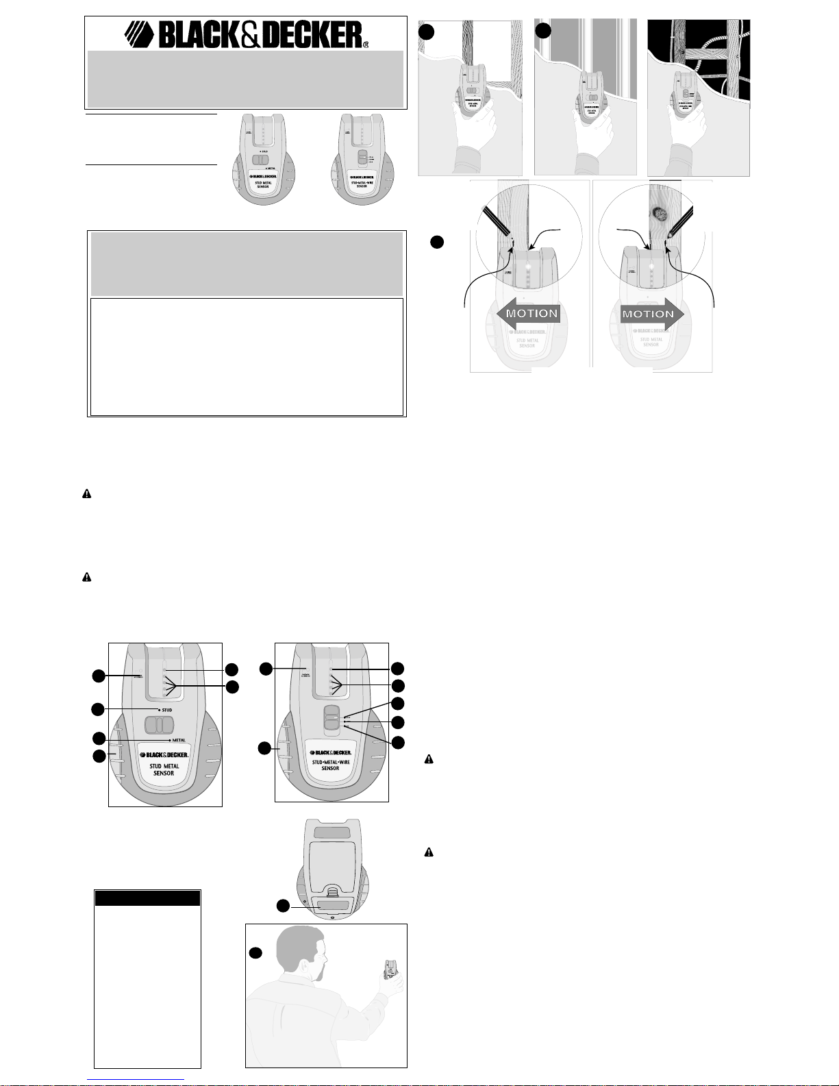
FEATURES
A.) Green LED (Light
Emitting Diode)
B.) Red LEDs (4)
C.) AC Detected LED
D.) Stud Mode LED
E.) Metal Mode LED
F.) Wire Mode LED
G.) On/Off Button
H.) Battery Compartment
Cover
2
B
G
A
Operating Instructions
INSTALLING THE BATTERY
Remove the battery compartment cover (H) by pressing in the tab in the center of the cover
and pulling back. Insert a fresh 9 volt alkaline battery into compartment and connect to battery
cable. Replace the battery compartment cover and snap shut.
CALIBRATION AND SCANNING
CALIBRATION
1.) For stud sensing, move slide switch to STUD position. Hold unit straight up and down and
place flat against wall as shown in Figure 2. For METAL sensing, move slide switch to METAL
position and calibrate by holding unit in air away from metal objects. For WIRE sensing, move
slide switch to AC WIRE position and calibrate by holding unit in air away from a “live”
unshielded electrical wire.
2.) Press in and hold the sensor ON/OFF button (G) while calibrating and continue holding in
button while scanning.
a.) The upper GREEN LED (A) will light,
b.) The unit will beep once while it is calibrating,
c.) The bottom RED LED will light.
SCANNING
STUD MODE FIGURE 2A
For stud sensing up to 3/4 in. (19mm) deep.
1.) After calibration, while still holding in button, slide sensor slowly, (Figure 2) horizontally
across surface of wall without lifting or tilting.
2.) The upper GREEN LED will light and a beeper will sound when an edge is detected, mark
that spot as shown in Figure 3.
Repeat this cycle coming from the other direction to confirm the mark.
METAL MODE FIGURE 2B
For metal (iron, etc.) sensing up to 2 inches (51mm) deep. For metal (copper, etc.) sensing up
to 1 inch (25mm) deep.
1.) After calibration, while still holding in button, slide sensor slowly across surface without
lifting or tilting.
2.) The upper GREEN LED will light and a beeper will sound when you are close to a metal
object, mark that spot. Reverse directions to locate other edge of target and mark spot. The
center of the two marks will be the center of the target object.
AC WIRE MODE FIGURE 2C (BDL153S ONLY)
For wire sensing up to 2 in. (51mm) deep.
1.) After calibration, while still holding in button, slide sensor slowly across surface without
lifting or tilting.
2.) The upper GREEN LED will light and a beeper will sound when you are close to a “live”
wire, mark that spot. Reverse directions to locate other edge of target and mark spot. The
center of the two marks will be the center of the target object.
The sensor detects from 90 to 250 V at 50 to 60 Hz AC in a “live” unshielded electrical wire.
WARNING: Always turn off the power when working near electrical wires, electric
shock may result.
Occasionally, pipes and electrical wiring may not be detected by this product. Observe
caution when cutting or drilling into areas that may contain concealed pipes or wiring. Always
turn off power when working near electrical wires. The sensor will not detect hot wires inside
metal pipe or metal conduit, behind metallic wall covering, or behind some plywood or other
dense materials.
AC DETECTION MODE
The sensor detects AC voltage in all settings. It assists in identifying when the sensor is near
AC wiring. Use the AC switch mode to fine tune the location of the wiring. Static charge may
spread detection 12 in. (30.4cm) on both sides of wire.
WARNING: Always turn off the power when working near electrical wires, electric
shock may result.
Occasionally, pipes and electrical wiring may not be detected by this product. Observe
caution when cutting or drilling into areas that may contain concealed pipes or wiring. Always
turn off power when working near electrical wires. The sensor will not detect hot wires inside
metal pipe or metal conduit, behind metallic wall covering, or behind some plywood or other
dense materials.
TIPS FOR OPTIMUM USE
• Test batteries before each use. Press and hold the on/off switch until the RED LED remains
on. Then move your free hand toward the back of the unit. The GREEN LED should illuminate
and then go out as you move your hand away from the unit. Replace the batteries if the
GREEN LED does not illuminate.
• Hold stud sensor straight up and down.
• Because studs are normally spaced 16 inches or 24 inches apart and are 1-1/2 inches wide,
beware of anything closer together or of a different width. Doors and windows are
constructed with studs and headers which are closer together.
• Avoid materials which have inconsistent density such as:
• Carpeting and padding
• Ceramic floor tile
• Wallpaper containing metallic foils or fibers. Generally, surfaces covered with regular
wallpaper or fabric will scan with no difference in function.
• Walls that are freshly painted and are still damp.
• Excessively thick plaster and lath.
Maintenance
Use only mild soap and damp cloth to clean the tool. Never let any liquid get inside the tool;
never immerse any part of the tool into a liquid.
Cat. No.BDL152S
BEFORE RETURNING THIS PRODUCT
FOR ANY REASON PLEASE CALL
1-800-544-6986
IF YOU SHOULD HAVE AQUESTION OR EXPERIENCE A
PROBLEM WITH YOUR BLACK & DECKER PRODUCT,
CALL 1-800-544-6986
BEFORE YOU CALL, HAVE THE FOLLOWING INFORMATION AVAILABLE, CATALOG No., TYPE No., AND
DATE CODE (e.g. 20000130M). IN MOST CASES, A BLACK & DECKER REPRESENTATIVE CAN
RESOLVE YOUR PROBLEM OVER THE PHONE. IF YOU HAVE A SUGGESTION OR COMMENT, GIVE
US A CALL. YOUR FEEDBACK IS VITAL TO BLACK & DECKER.
WIRE
WIRE
C
D
E
B
A
C
E
F
G
D
2A
2B
2C
1
LED brightens to
signal edge of stud...
2
*Recess edge
indicates
approximate
center of stud...
3
User can mark
the location for
nailing, securing,
etc...
3
User can mark
the location for
nailing, securing,
etc...
2
*Recess edge
indicates
approximate
center of stud...
3
H
Cat. No.BDL153S
Cat. No.BDL152S
Cat. No.BDL153S
*Based on stud 1-1/2 inches wide
Page 2
IMPORTANT: To assure product SAFETY and RELIABILITY, repairs, maintenance and
adjustment (other than those listed in this manual) should be performed by authorized service
centers or other qualified service personnel, always using identical replacement parts.
WARNING: The use of any accessory not recommended for use with this tool could be
hazardous.
FCC Warning
This device complies with part 15 of the FCC Rules. Operation is subject to the following two
conditions: (1) This device may not cause harmful interference, and (2) this device must accept
any interference received, including interference that may cause undesired operation.
Service Information
All Black & Decker Service Centers are staffed with trained personnel to provide customers
with efficient and reliable power tool service. Whether you need technical advice, repair, or
genuine factory replacement parts, contact the Black & Decker location nearest you. To find
your local service location, refer to the yellow page directory under "Tools—Electric" or call:
1-800-544-6986 or visit www.blackanddecker.com
Full Two-Year Home Use Warranty
Black & Decker (U.S.) Inc. warrants this product for two years against any defects in material
or workmanship. The defective product will be replaced or repaired at no charge in either of two
ways.
The first, which will result in exchanges only, is to return the product to the retailer from whom it
was purchased (provided that the store is a participating retailer). Returns should be made
within the time period of the retailer’s policy for exchanges (usually 30 to 90 days after the
sale). Proof of purchase may be required. Please check with the retailer for their specific return
policy regarding returns that are beyond the time set for exchanges.
The second option is to take or send the product (prepaid) to a Black & Decker owned or
authorized Service Center for repair or replacement at our option. Proof of purchase may be
required. Black & Decker owned and authorized Service Centers are listed under "ToolsElectric" in the yellow pages of the phone directory and on our website
www.blackanddecker.com.
This warranty does not apply to accessories. This warranty gives you specific legal rights and
you may have other rights which vary from state to state. Should you have any questions,
contact the manager of your nearest Black & Decker Service Center. This product is not
intended for commercial use.
FREE WARNING LABEL REPLACEMENT: If your warning labels become illegible or are
missing, call 1-800-544-6986 for a free replacement.
AVERTISSEMENT : Afin de réduire les risques de blessure, l’utilisateur doit lire et
comprendre le présent guide.
CONSERVER CES DIRECTIVES
CONSIGNES DE SÉCURITÉ
• Ne pas utiliser le localisateur de montants dans une atmosphère explosive, comme en
présence de liquide, de gaz ou de poussière inflammable.
• N’utiliser que des piles alcalines de 9 volts conçues pour cet outil; l’usage de tout autre
type de pile pourrait entraîner des risques d’incendie.
MISE EN GARDE : L’épaisseur du matériau, le type de matériau, le taux d’humidité ou
d’autres facteurs peuvent influencer les résultats obtenus. Le localisateur de montants peut
détecter des tuyaux ou des fils électriques, comme il le fait pour des montants, selon leur
emplacement par rapport à la surface du mur. Puisque l’outil peut en effet détecter ces
éléments comme s’il s’agissait de montants, il faut faire preuve d’une grande prudence
lorsqu’on perce un trou, qu’on enfonce un clou ou qu’on effectue une coupe dans un mur,
un plancher ou un plafond pouvant camoufler des tuyaux ou des fils électriques. Puisque
l’espace entre chaque montant varie généralement entre 406 et 610 mm (16 et 24 po), et
que ceux-cimesurent normalement près de 38 mm (1 1/2 po) de largeur, il faut tenir compte
du fait qu’ils sont peut-être plus rapprochés ou qu’ils sont de largeurs différentes. Toujours
couper le courant avant de travailler à proximité de fils électriques.
Mode d’emploi
INSTALLATION DE LA PILE
Retirer le couvercle du compartiment de la pile (H) en enfonçant d’abord la languette au
centre du couvercle vers l’intérieur, puis en la tirant vers l’arrière. Insérer une pile alcaline de
9 volts complètement chargée dans le compartiment et le raccorder au câble de piles.
Replacer le couvercle et le fermer d’un coup sec.
ÉTALONNAGE ET BALAYAGE
ÉTALONNAGE
1.) Pour détecter les montants, déplacer l’interrupteur à glissière jusqu’à la position « STUD
». Tenir l’unité le plus possible à la verticale et la placer à plat contre le mur, tel qu’illustré à la
figure 2. Pour détecter le MÉTAL, déplacer l’interrupteur à glissière jusqu’à la position «
METAL », puis l’étalonner en éloignant l’unité du mur ainsi que des objets en métal. Pour
détecter les fils, déplacer l’interrupteur à glissière jusqu’à la position « AC WIRE », puis
éloigner l’unité des fils électriques non blindés « sous tension ».
2.) Enfoncer le bouton marche-arrêt du localisateur de montants (G) durant l’étalonnage; ne
le relâcher qu’après avoir terminé.
a.) Le témoin à DEL VERT (A) s’allume,
b.) L’unité émet un signal sonore pour indiquer qu’il s’étalonne.
c.) Le bouton à DEL ROUGE s’allume.
BALAYAGE
MODE « MONTANT », FIGURE 2A
Mode servant à détecter les montants à plus de 19 mm (3/4 po) de profondeur.
1.) Après l’étalonnage (le bouton est toujours enfoncé), faire glisser lentement l’outil (figure 2)
horizontalement contre la surface du mur, sans le soulever ni l’incliner.
2.) Le témoin à DEL VERT s’allume et l’outil émet un signal sonore dès que l’outil détecte un
bord; tracer une marque à cet endroit, tel qu’illustré à la figure 3.
Reprendre le mouvement en sens inverse pour confirmer la marque.
MODE « MÉTAL», FIGURE 2B
Mode servant à détecter les objets en métal situés à une profondeur allant jusqu’à 51 mm/ 2
po (dans le cas du fer, etc.), ou jusqu’à 25 mm/1 po (dans le cas du cuivre, etc.)
1.) Après l’étalonnage (le bouton est toujours enfoncé), faire glisser lentement l’outil contre la
surface, sans le soulever ni l’incliner.
2.) Le témoin à DEL VERT s’allume et l’outil émet un signal sonore dès que l’outil s’approche
d’un objet en métal; tracer une marque à cet endroit. Reprendre le mouvement en sens
inverse pour trouver l’autre bord de l’objet, puis tracer une deuxième marque. Le centre de
ce dernier est situé entre les deux repères.
MODE « FIL ÉLECTRIQUE C.A. », FIGURE 2C (MODÈLE BDL153S SEULEMENT)
Mode servant à détecter les fils à 51 mm (2 po) ou moins de profondeur.
1.) Après l’étalonnage, (le bouton est toujours enfoncé), faire glisser l’outil lentement sur la
surface, en évitant de le soulever ou de l’incliner.
2.) Le témoin à DEL VERT s’allume et l’outil émet un signal sonore dès que l’outil s’approche
d’un fil sous tension; tracer une marque à cet endroit. Reprendre le mouvement en sens
inverse pour trouver l’autre bord de l’objet, puis tracer une deuxième marque. Le centre de
ce dernier est situé entre les deux repères.
L’outil peut détecter des fils électriques non blindés sous tension c. a. de 90 à 250 V et de 50
à 60 Hz.
AVERTISSEMENT: Toujours couper le courant électrique avant de travailler à
proximité de fils électriques afin d’éviter les risques de choc électrique.
Il peut arriver, à l’occasion, que l’outil ne détecte pas les tuyaux ou les fils électriques. Il faut
faire preuve d’une grande prudence lorsqu’on coupe ou qu’on perce dans des endroits
susceptibles de camoufler des tuyaux ou des fils. Toujours couper le courant avant de
travailler à proximité de fils électriques. L’outil ne détectera pas les fils chauds protégés à
l’intérieur d’un tuyau ou d’un conduit en métal ou dissimulés derrière un couvre-mur en métal
ou un matériau épais tel que le contreplaqué.
MODE « DÉTECTION C.A. »
L’outil détecte les fils à courant alternatif, quel que soit le mode utilisé, afin d’aviser
l’utilisateur que des fils de circuit électrique c.a. sont à proximité. Utiliser alors le mode « fil
électrique c.a. » pour trouver l’emplacement exact du filage; la présence d’une charge
statique peut toutefois faire en sorte que l’outil indique la présence d’un fil à 30,4 cm (12 po)
de chaque côté de son emplacement exact.
AVERTISSEMENT: Toujours couper le courant électrique avant de travailler à
proximité de fils électriques afin d’éviter les risques de choc électrique.
Il peut arriver, à l’occasion, que l’outil ne détecte pas les tuyaux ou les fils électriques. Il faut
faire preuve d’une grande prudence lorsqu’on coupe ou qu’on perce dans des endroits
susceptibles de camoufler des tuyaux ou des fils. Toujours couper le courant avant de
travailler à proximité de fils électriques. L’outil ne détectera pas les fils chauds protégés à
l’intérieur d’un tuyau ou d’un conduit en métal ou dissimulés derrière un couvre-mur en métal
ou un matériau épais tel que le contreplaqué.
CONSEILS PRATIQUES POUR UN USAGE OPTIMAL
• Tester les piles avant chaque utilisation. Enfoncer l’interrupteur de marche-arrêt jusqu’à ce
que le témoin à DEL ROUGE s’allume. Déplacer la main libre vers l’arrière de l’unité; le
témoin VERT devrait s’allumer. Se diriger ensuite vers l’extérieur à mesure qu’on éloigne la
See ‘Tools-Electric’
– Yellow Pages –
for Service & Sales
Imported by
Black & Decker (U.S.) Inc.,
701 E. Joppa Rd.
Towson, MD 21286 U.S.A.
Possible Cause
• Weak battery.
• Nothing to detect in that
area.
•May have been
calibrated over a stud.
Solution
• Replace with fresh batteries.
• Start again moving farther to either
side.
Problem
• LEDs do not light.
• Switch to Metal or AC Wire mode.
• LEDs light in too many
places.
• Detects other objects
besides studs.
• Electrical wiring and
metal or plastic pipes
may be near or touching
back surface of wall.
TTTTRRRROOOOUUUUBBBBLLLLEEEESSSSHHHHOOOOOOOOTTTTIIIINNNNGG
GG
CAUTION: Always turn off
the power when working near
electrical wires.
• Use caution if area has plywood,
thick wood backing behind drywall,
or thicker than normal walls.
• Remember studs are normally
spaced 16 inches or 24 inches
apart and are 1-1/2 inches wide.
• If a switch controls an outlet, make
sure the it is ON for detection.
• You suspect electrical
wires, but do not detect
any.
• If wires are shielded
behind metallic wall
coverings, or in metal
conduit, the sensor will
not be able to detect
them.
• The wires may not be
“live”.
• Wires may be too deep
to sense.
• Avoid calibrating over metal and
always calibrate in the air for best
sensitivity.
• Difficulty detecting metal.
• Unit calibrated over
metal.
• Metal objects are too
deep.
GUIDE D’UTILISATION
No de catalogue BDL152S No de catalogue BDL153S
Avant de retourner ce produit
pour quelque raison que ce soit, composez le 1800 544-6986
Si vous avez des questions ou vous Èprouveun problËme
avec líoutil, composez le1 800 544-6986.
B
G
A
WIRE
C
D
E
B
A
C
E
F
G
D
Cat. No.BDL152S
Cat. No.BDL153S
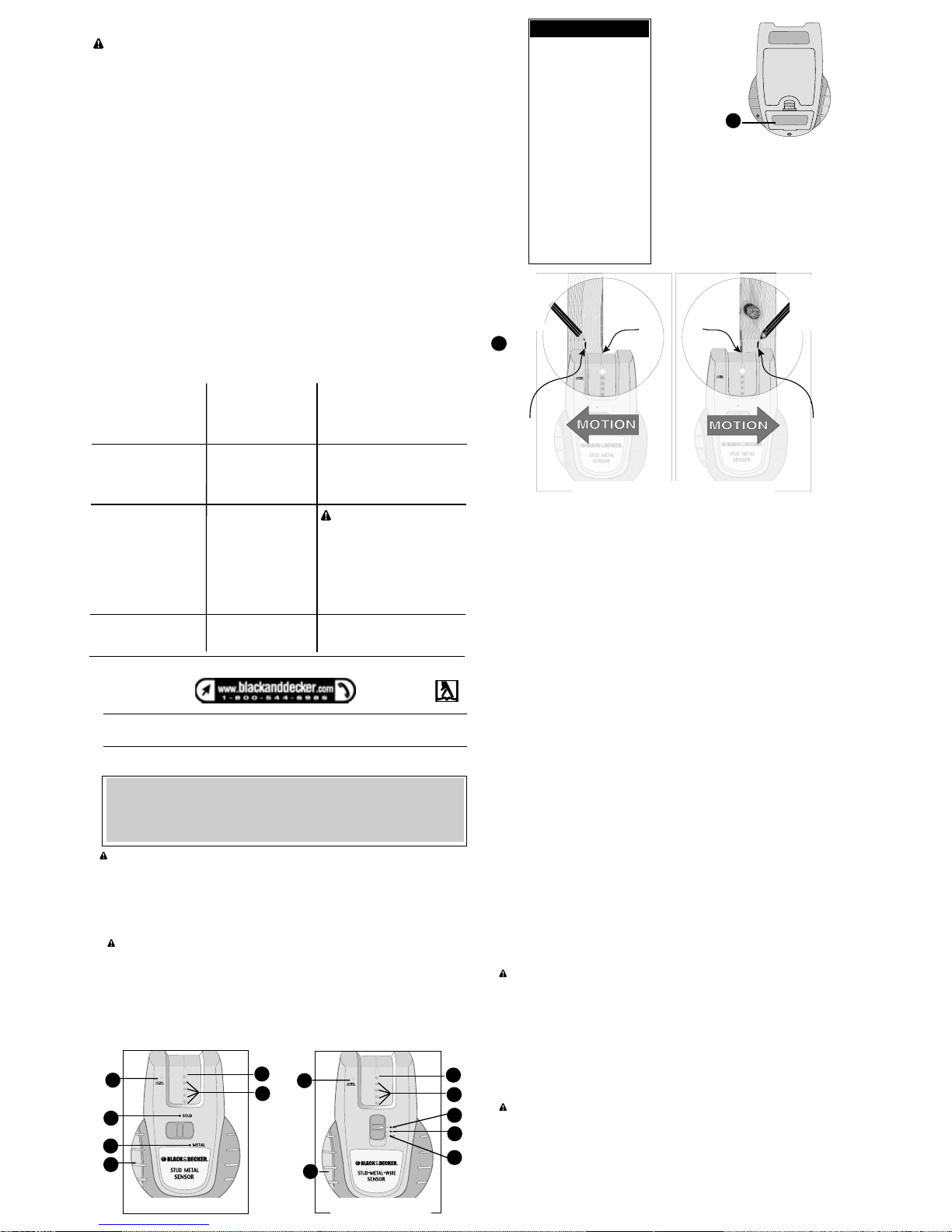
COMPOSANTS
A.) Témoin à DEL vert
(diode électroluminescente)
B.) Témoins à DEL rouge
(4)
C.) Témoin à DEL en mode
« détection c.a.
D.) Témoin à DEL en mode
« montant
E.) Témoin à DEL en mode
« métal
F.) Témoin à DEL en
mode« fil
G.) Bouton de marchearrêt
H.) Couvercle du
compartiment de la pile
H
1
Le témoin à DEL s’allume pour indiquer le
bord du montant...
2
*Le bord en
retrait indique le
centre du mon-
tant...
3
L’utilisateur peut
marquer l’endroit
où il doit clouer,
fixer, etc...
3
L’utilisateur peut
marquer l’endroit
où il doit clouer,
fixer, etc...
2
*Le bord en
retrait indique le
centre du mon-
tant...
3
*Pour un goujon de 38 mm (1 1/2 po) de largeur
Page 3

main de l’unité. Remplacer les piles lorsque le témoin VERT ne s’allume plus.
• Tenir le localisateur de montants le plus possible à la verticale.
• Puisque l’espace entre chaque montant varie généralement entre 406 et 610 mm (16 et 24
po), et que ceux-ci mesurent près de38 mm (1 1/2 po) de largeur, il faut tenir compte du fait
qu’ils sont peut-être plus rapprochés ou qu’ils sont de largeurs différentes. Les montants et
les linteaux des portes et fenêtres sont plus rapprochés les uns des autres.
• Éviter les matériaux ayant une densité inconsistante, tels que :
• les moquettes et les garnitures;
• les tuiles en céramique;
• le papier peint contenant des feuilles ou des fibres métalliques. Généralement, le
balayage des surfaces recouvertes d’un papier peint ou d’un tissu ordinaire
s’effectue normalement;
• les murs fraîchement peints qui n’ont pas eu le temps de sécher;
• le plâtre et les lattes ayant une épaisseur excessive.
ENTRETIEN
Nettoyer l’outil au moyen d’un savon doux et d’un linge humide seulement. Ne jamais
laisser de liquide s’infiltrer à l’intérieur de l’outil ni tremper ce dernier dans un liquide
quelconque.
IMPORTANT : Pour assurer la SÉCURITÉ et la FIABILITÉ de ce produit, toutes les
opérations de réparation, d’entretien et de réglage (autres que celles décrites aux
présentes) doivent être effectuées dans un centre de service autorisé ou par du personnel
qualifié; on ne doit utiliser que des pièces de rechange identiques.
AVERTISSEMENT : L’usage d’un accessoire non recommandé peut présenter un danger.
Avertissement de la FCC
Ce dispositif est conforme aux dispositions de la partie 15 des règlements de la FCC. Le
fonctionnement doit respecter les deux conditions suivantes : (1) ce dispositif ne doit pas
causer de brouillage nuisible, et (2) ce dispositif doit accepter tout brouillage qu’il reçoit, y
compris celui qui cause un fonctionnement indésirable.
INFORMATION SUR LES SERVICES
Tous les centres de service Black & Decker sont dotés de personnel qualifié en matière
d’outillage électrique; ils sont donc en mesure d’offrir à leur clientèle un service efficace et
fiable. Pour obtenir un conseil technique ou une pièce d’origine ou pour faire réparer un
outil, on peut communiquer avec le centre Black & Decker le plus près. Pour obtenir un
numéro de téléphone, consulter les pages jaunes sous la rubrique « Outils – électriques »,
ou composer le
1 800 544-6986 ou encore, visiter notre site Web au www.blackanddecker.com.
GARANTIE COMPLÈTE DE DEUX ANS POUR USAGE RÉSIDENTIEL
Black & Decker (U.S.) Inc. garantit ce produit pour une période de deux ans contre tout
défaut de matériel ou de fabrication. Le produit défectueux sera réparé ou remplacé sans
frais, suivant l’une des deux méthodes suivantes.
La première méthode consiste en un échange seulement. On doit retourner le produit au
détaillant qui l’a vendu (pourvu qu’il s’agisse d’un détaillant participant), en respectant les
délais stipulés dans sa politique relative aux échanges (normalement de 30 à 90 jours après
la vente). Une preuve d’achat peut être requise. On doit vérifier la politique de retour du
détaillant pour tout produit retourné après le délai prescrit pour les échanges.
La deuxième méthode consiste à apporter ou à envoyer le produit (prépayé) à un centre
Black & Decker ou à un centre de service autorisé aux fins de réparation ou de
remplacement, selon notre choix. Une preuve d’achat peut être requise. Les centres Black
& Decker et les centres de service autorisés sont répertoriés dans les pages jaunes sous la
rubrique « Outils – électriques », et sur le site Web www.blackanddecker.com.
Cette garantie ne s’applique pas aux accessoires. Cette garantie confère des droits légaux
particuliers à l’acheteur, mais celui-ci pourrait aussi bénéficier d’autres droits variant d’un
territoire à l’autre.
Toute question doit être adressée au gérant du centre Black & Decker le plus près. Ce
produit n’est pas destiné à un usage commercial.
Cause probable
• Les piles sont affaiblies.
• L’outil ne détecte aucun
montant.
•L’outil a été étalonné au
niveau d’un montant.
Solution
• Remplacer les piles par des piles
complètement chargées.
• Recommencer le balayage en se
déplaçant plus loin de chaque côté
du montant.
Problème
• Les témoins à DEL ne
s’allument pas
• Mettre l’outil en mode métal ou
détection de fil à courant alternatif
• Les témoins à DEL
s’allument trop souvent.
• L’outil détecte d’autres
objets et non des
montants.
• L’outil balaye trop près
de fils électriques ou de
tuyaux en métal ou en
plastique ou ces derniers
touchent la face arrière
du mur.
DDDDIIIIAAAAGGGGNNNNOOOOSSSSTTTTIIIICCCC DDDD’’’’AAAANNNNOOOOMMMMAAAALLLLIIIIEEEESS
SS
MISE EN GARDE :
Toujours couper le courant
électrique avant de travailler à
proximité de fils électriques.
• Faire preuve d’une grande
prudence en présence de
contreplaqué, de renforts en bois
épais placés derrière une cloison
ou un mur plus épais que
d’habitude
• Remarque : l’espace entre chaque
montant varie généralement entre
406 et 610 mm (16 et 24 po) et
ceux-ci mesurent près de 38 mm
(1 1/2 po) de largeur.
• Lorsque la prise fonctionne au
moyen d’un interrupteur, s’assurer
que ce dernier est en position de
marche. Sinon, l’outil ne
fonctionnera pas.
• Bien qu’une défectuosité
au niveau des fils
électriques soit
soupçonnée, aucune
n’est détectée.
• Si les fils sont protégés
derrière un couvre-mur
métallique ou dissimulés
dans un conduit en
métal, l’outil ne pourra
pas les détecter.
• Les fils peuvent être «
hors tension ».
• Les fils peuvent être
installés trop
profondément pour être
détectés.
• Éviter d’étalonner l’outil au niveau
du métal; toujours l’éloigner du mur
lors de l’étalonnage pour obtenir la
meilleure sensibilité.
• L’outil détecte
difficilement le métal.
• L’outil a été étalonné au
niveau du métal.
• Les objets en métal
sont trop profonds.
Imported by / Importé par
Black & Decker Canada Inc.
100 Central Ave.
Brockville (Ontario) K6V 5W6
Voir la rubrique “Outils électriques”
des Pages Jaunes
pour le service et les ventes.
MANUAL DE INSTRUCCIONES
No. Cat. BDL152S No. Cat. BDL153S
POR FAVOR LLAME AL 1-800-544-6986 ANTES DE
DEVOLVER ESTE PRODUCTO, CUALQUIERA SEA LA
RAZÓN.
LLAME AL 1-800-544-6986 SI TIENE ALGUNA CONSULTA O
PROBLEMA CON SU PRODUCTO BLACK & DECKER.
ADVERTENCIA: Para reducir el riesgo de lesiones, el usuario deberá leer y comprender el
manual de instrucciones.
GUARDE ESTAS INSTRUCCIONES
INSTRUCCIONES DE SEGURIDAD
• No opere el buscador de pies derechos en ambientes explosivos tales como en la presencia
de líquidos, gases o polvos inflamables.
• Use el buscador de pies derechos sólo con una pila alcalina de 9 voltios. El uso de cualquier
otra batería puede causar incendios.
ATENCIÓN: El grosor y tipo de material, su contenido de humedad y otras variables pueden
afectar el funcionamiento del sensor. El sensor puede detectar instalaciones eléctricas o
tuberías de la misma manera que detecta pies derechos, dependiendo de su ubicación en
relación a la superficie de la pared. Tenga cautela cuando taladre, clave o corte en paredes,
pisos y techos que pudieran contener instalaciones eléctricas o tuberías. Estos objetos
pueden ser detectados por el ‘Stud Sensor’ de la misma manera en que detecta pies
derechos.Los pies derechos de las paredes generalmente se encuentran en intervalos de
406 ó 610 mm (16 ó 24 pulg.) y usualmente tienen 38 mm (1-1/2 pulg.) de ancho. Por este
motivo, tenga cuidado si encuentra algo en intervalos menores o de diferente ancho.
Siempre corte la electricidad cuando trabaje cerca de hilos eléctricos.
Instrucciones de operación
INSTALACIÓN DE LA PILA
Para quitar la cubierta del compartimiento de pilas (H), presione la lengüeta del centro de la
cubierta y ábrala. Inserte una pila alcalina de 9 voltios nueva en el compartimiento y
conéctela al cable de la pila. Reponga la cubierta del compartimiento de pilas y ciérrela bien.
CALIBRADO Y EXPLORACIÓN
CALIBRADO
1.) Para buscar pies derechos, deslice el conmutador a la posición STUD. Sostenga el
dispositivo derecho y póngalo contra la pared, como lo muestra la Figura 2. Para buscar
estructuras de METAL, deslice el conmutador a la posición METAL y calibre la unidad
sosteniéndola en el aire, alejada de objetos metálicos. Para buscar instalaciones eléctricas,
deslice el conmutador a la posición AC WIRE y calibre la unidad sosteniéndola en el aire,
alejada de hilos eléctricos cargados sin blindar.
2.) Presione y sostenga el botón ON/OFF (de encendido y apagado) del sensor (G)
mientras calibre la unidad y siga sosteniendo el botón mientras explore.
a.) El LED VERDE superior (A) se iluminará,
b.) La unidad emitirá un solo tono (‘bip’) mientras se calibra,
c.) Se iluminará el LED ROJO inferior.
EXPLORACIÓN
MODALIDAD STUD FIGURA 2A
Para buscar pies derechos que se encuentran a hasta 3/4 pulg. (19 mm) de profundidad.
1.) Luego de calibrarlo, aun sosteniendo el botón, deslice el sensor lentamente, (Figura 2)
en forma horizontal por la superficie de la pared sin levantar ni inclinarlo.
2.) El LED VERDE superior se iluminará y emitirá un tono (‘bip’) cuando detecte el borde del
objeto; marque ese punto, como lo muestra la Figura 3.
Repita este ciclo desde la dirección contraria para confirmar la marca.
B
G
A
WIRE
C
D
E
B
A
C
E
F
G
D
Cat. No.BDL152S
Cat. No.BDL153S
CARACTERÍSTICAS
A.) LED (diodo
fotoemisor) verde
B.) LED rojos (4)
C.) LED de detección de
corriente alterna
D.) LED modalidad Stud
(pies derechos)
E.) LED modalidad Metal
(objetos de metal)
F.) LED modalidad Wire
(hilos eléctricos)
G.) Botón On/Off (de
encendido y apagado)
H.) Cubierta del
compartimiento de pilas
H
1
El LED se ilumina
para señalar el borde
del pie derecho...
2
*Borde hundido
señala el centro
del pie derecho...
3
El usuario puede
marcar la ubi-
cación para
clavar, fijar, etc...
3
El usuario puede
marcar la ubi-
cación para
clavar, fijar, etc...
2
*Borde hundido
señala el centro
del pie derecho...
3
*Si el pie derecho es de 3,8 cm (1-1/2 pulg.) de ancho
Page 4

MODALIDAD METAL FIGURA 2B
Encuentra estructuras de metal (hierro, etc.) a hasta 2 pulg. (51 mm) de profundidad.
Encuentra estructuras de metal (cobre, etc.) a hasta 1 pulg. (25 mm) de profundidad.
1.) Luego de calibrarla, aun sosteniendo el botón, deslice el sensor lentamente por la
superficie sin levantar o inclinar.
2.) El LED VERDE superior se iluminará y emitirá un tono (‘bip’) cuando se encuentren
próximos a un objeto de metal; marque ese punto. Siga el mismo procedimiento desde la
dirección inversa para ubicar el otro borde del objeto y marque ese punto. El centro de las
dos marcas será el centro del objeto encontrado.
MODALIDAD AC WIRE FIGURA 2C (SÓLO BDL153S)
Para encontrar instalaciones eléctricas a hasta 2 pulg. (51 mm) de profundidad.
1.) Luego de calibrarla, aun sosteniendo el botón, deslice el sensor lentamente por la
superficie sin levantar o inclinar.
2.) El LED VERDE superior se iluminará y emitirá un tono (‘bip’) cuando se encuentren
próximos a un hilo cargado; marque ese punto. Siga el mismo procedimiento desde la
dirección inversa para ubicar el otro borde del objetivo y marque ese punto. El centro de
las dos marcas será el centro de la instalación eléctrica ubicada.
El sensor detecta entre 90 y 250 V, entre 50 y 60 Hz de corriente alterna en un hilo
eléctrico cargado sin blindar.
ADVERTENCIA: Siempre corte la corriente cuando trabaje en proximidad a hilos
eléctricos para evitar que ocurran descargas eléctricas.
Ocasionalmente este producto puede no detectar tuberías e instalaciones eléctricas.
Tenga cautela cuando corte o taladre en áreas que podrían contener tuberías o
instalaciones eléctricas ocultas. Siempre corte la corriente cuando trabaje en proximidad a
hilos eléctricos. El sensor no detectará hilos calientes si estos se encuentran dentro de
tuberías o ductos metálicos, detrás de revestimientos murales metálicos o detrás de
algunos tipos de contrachapado u otros materiales densos.
MODALIDAD DE DETECCIÓN DE CORRIENTE ALTERNA
El sensor detecta voltaje de corriente alterna en todas las configuraciones. Ayuda en la
identificación de instalaciones eléctricas de corriente alterna próximas al sensor. Utilice la
modalidad AC del conmutador para ubicar la instalación eléctrica con mayor precisión. Es
posible que una carga de estática disperse el punto de detección en 12 pulg. (30,4 cm) a
ambos lados del hilo.
ADVERTENCIA: Siempre corte la corriente cuando trabaje en proximidad a hilos
eléctricos para evitar que ocurran descargas eléctricas.
Ocasionalmente este producto puede no detectar tuberías e instalaciones eléctricas.
Tenga cautela cuando corte o taladre en áreas que podrían contener tuberías o
instalaciones eléctricas ocultas. Siempre corte la corriente cuando trabaje en proximidad a
hilos eléctricos. El sensor no detectará hilos calientes si estos se encuentran dentro de
tuberías o ductos metálicos, detrás de revestimientos murales metálicos o detrás de
algunos tipos de contrachapado u otros materiales densos.
CONSEJOS PARA SU USO ÓPTIMO
• Pruebe las pilas cada vez que lo vaya a utilizar. Presione y sostenga el botón on/off hasta
que el LED ROJO se ilumine. Luego, ponga la otra mano detrás del dispositivo. La luz
VERDE debería iluminarse y luego apagarse cuando retire su mano del dispositivo.
Reemplace las pilas si el LED VERDE no se ilumina.
• Sostenga el buscador de pies derechos en forma recta.
• Los pies derechos de las paredes generalmente se encuentran en intervalos de 16 ó 24
pulgadas (406 ó 610 mm.) y tienen 1_ pulgadas (38 mm.) de ancho. Por este motivo, tenga
cuidado si encuentra algo en intervalos menores o de diferente ancho. Los pies derechos y
tizones de puertas y ventanas se encuentran en intervalos menores.
• Evite usarlo con materiales de densidad irregular tales como:
• Alfombra y fieltro
• Baldosa de cerámica
• Papel mural que contenga láminas o fibras metálicas. El funcionamiento del dispositivo no
se verá generalmente afectado en la exploración de superficies cubiertas con papel mural
regular o tela.
• Paredes recién pintadas aún húmedas
• Paredes de listones y yeso excesivamente gruesas
MANTENIMIENTO
Para limpiar la herramienta, sólo utilice un paño húmedo y jabón suave. Jamás permita que
le entre líquido a la herramienta; nunca sumerja ninguna parte de la herramienta.
IMPORTANTE: Las reparaciones, el mantenimiento y los ajustes del dispositivo (fuera de
los mencionados en este documento) deberán ser realizados por centros de servicio
autorizados u otro personal de servicio calificado, utilizando siempre repuestos idénticos,
para asegurar la SEGURIDAD y FIABILIDAD de la unidad.
ADVERTENCIA: El uso de cualquier accesorio que no sea recomendado para ser
utilizado con esta herramienta podría ser peligroso.
ADVERTENCIA DE LA FCC
Este dispositivo cumple con la sección 15 de las Normas FCC. Su operación está sujeta a
las siguientes dos condiciones: (1) Este dispositivo no puede causar interferencia dañina y
(2) este dispositivo debe aceptar cualquier interferencia que reciba, incluyendo aquella
interferencia que pudiera causar una operación no deseada.
INFORMACIÓN DE SERVICIO
Todos los Centros de Servicio Black & Decker están dotados de personal capacitado para
proporcionar un servicio técnico eficiente y fiable a las máquinas herramientas de nuestros
clientes. Contacte al local Black & Decker más cercano para obtener consejos técnicos,
reparaciones o repuestos de fábrica originales. Para encontrar el local de servicio más
cercano, busque en las páginas amarillas bajo “Herramientas eléctricas”, llame al
1-800-544-6986 o visite nuestra página web www.blackanddecker.com
GARANTÍA COMPLETA DE DOS AÑOS PARA USO DOMÉSTICO
Black & Decker (U.S.) Inc. garantiza este producto por dos años contra cualquier defecto
en su material o fabricación. Existen dos opciones para reemplazar o reparar el producto
defectuoso, sin costo.
La primera, la cual resultará sólo en un cambio, es devolver el producto al vendedor del
cual fue comprado (siempre que sea un local participante). Las devoluciones deberán
realizarse durante el plazo especificado en la política de devoluciones del vendedor
(generalmente entre 30 y 90 días después de la fecha de compra). Puede que sea
necesario presentar prueba de compra. Por favor averigüe cuál es la política del vendedor
para devoluciones efectuadas más allá del plazo para cambios.
La segunda opción es llevar o enviar el producto (con franqueo pagado) a un centro de
servicio autorizado o al Centro de Servicio Black & Decker para su reparación o
reemplazo, a decisión nuestra. Puede que sea necesario presentar prueba de compra. Los
centros de servicio autorizados y Centros de Servicio Black & Decker se encuentran en las
páginas amarillas bajo “Herramientas eléctricas” y en nuestra página web
www.blackanddecker.com.
Esta garantía no aplica a los accesorios. Esta garantía le da derechos legales específicos
además de los cuales puede tener otros, los cuales varían entre estados. Si tuviese alguna
pregunta, contacte al gerente de su Centro de Servicio Black & Decker más cercano. Este
producto no es para uso comercial.
Posible causa
• La pila está gastada.
• No hay nada que
detectar en esa área.
• Puede haber sido
calibrado sobre un pie
derecho.
Solución
• Reemplace con pilas nuevas
• Vuelva a comenzar, yendo más
lejos en ambas direcciones.
Problema
• Los LED no se iluminan.
• Cambie de modalidad a Metal o
AC Wire.
• Los LED se iluminan en
demasiados lugares.
• Detecta otros objetos,
además de los pies
derechos.
• Puede que haya una
instalación eléctrica y
cañerías de metal o
plástico cerca de o
tocando la superficie
posterior de la pared.
RRRREEEESSSSOOOOLLLLUUUUCCCCIIIIÓÓÓÓNNNN DDDDEEEE PPPPRRRROOOOBBBBLLLLEEEEMMMMAAAASS
SS
ATENCIÓN: Siempre apague
la corriente cuando trabaje en
proximidad a hilos eléctricos.
• Tenga cautela si el área tiene
contrachapado o respaldo de
madera gruesa detrás de muros
secos o si las paredes son más
gruesas de lo normal.
• Recuerde que los pies derechos de
las paredes generalmente se
encuentran en intervalos de 16 ó
24 pulgadas (406 mm ó 610 mm) y
tienen 1_ pulgadas (38 mm) de
ancho.
• Si una toma de corriente es
controlada por un conmutador,
asegúrese que esté en ON para
poder detectar la instalación
eléctrica.
• Sospecha que hay hilos
eléctricos pero no detecta
ninguno.
• Si los hilos están
protegidos tras
revestimientos metálicos
de pared o en ductos
metálicos, el sensor no
podrá detectarlos.
• Puede que los hilos no
estén cargados.
• Puede que los hilos
estén demasiado
profundos para
encontrarlos.
ARA REPARACION Y SERVICIO DE SUS HERRAMIENTAS ELECTRICAS FAVOR DE
DIRIGIRSE AL CENTRO DE SERVICIO MAS CERCANO
CULIACAN Av. Nicolas Bravo #1063 Sur (56 77) 12 42 10
GAUDALAJARA Av. La Paz #1770 (33 38) 26 69 78
LEON Polara #32 (47 77) 13 14 56
MEXICO Sonora #134 Hiprodromo Condesa (55 55) 53 99 79
MERIDA Calle 63 #459 (99 99) 23 54 90
MONTERREY Av. Francisco I. Madero Pte. 1820-A (81 83) 72 11 25
PUEBLA 17 Norte #2057 (22 22) 46 90 20
QUERETARO Av. Madero 139 Pte. (44 22) 14 60 60
SAN LOUIS POTOSI Pedro Moreno #408 Fracc. la Victoria (44 48) 14 25 67
TORREON Blvd. Independencia, 96 pte. (87 17) 16 52 65
VERACRUZ Prolongación Diaz Miron #4280 (29 99) 21 70 18
VILLAHERMOSA Zaragoza #105 (99 33) 12 53 17
PARA OTRAS LOCALIDADES LLAME AL: (55) 5326-7100 INFORMACIÓN DE SERVICIO
IMPORTADO: BLACK & DECKER S.A. DE C.V.
BOSQUES DE CIDROS ACCESO RADIATAS NO. 42
COL. BOSQUES DE LAS LOMAS.
05120 MÉXICO, D.F
TEL. 3-26-71-00
Epecificaciones
BDL152/153S
Tensión de alimentación 9V
 Loading...