

Page 1

CUSTOMER
SUPPORT
INFORMATION
Order toll-free in the U.S.: Call 877-877-BBOX (outside U.S. call 724-746-5500)
FREE technical support 24 hours a day, 7 days a week: Call 724-746-5500 or fax 724-746-0746
Mailing address: Black Box Corporation, 1000 Park Drive, Lawrence, PA 15055-1018
Web site: www.blackbox.com • E-mail: info@blackbox.com
JANUARY 2002
SM900A SM906C SM910C
SM901A SM907C SM911C
SM902C SM908C SM912A
SM904C SM909C SM950A
SM950A-220
Pro Switching System II with
Management Software
Page 2

1
FCC AND IC RFI STATEMENTS
FEDERAL COMMUNICATIONS COMMISSION AND INDUSTRY CANADA
RADIO-FREQUENCY INTERFERENCE STATEMENTS
This equipment generates, uses, and can radiate radio-frequency energy, and if not
installed and used properly, that is, in strict accordance with the manufacturer’s
instructions, may cause interference to radio communication. It has been tested
and found to comply with the limits for a Class A computing device in accordance
with the specifications in Subpart B of Part 15 of FCC rules, which are designed to
provide reasonable protection against such interference when the equipment is
operated in a commercial environment. Operation of this equipment in a
residential area is likely to cause interference, in which case the user at his own
expense will be required to take whatever measures may be necessary to correct
the interference.
Changes or modifications not expressly approved by the party responsible
for compliance could void the user’s authority to operate the equipment.
This digital apparatus does not exceed the Class A limits for radio noise emission from
digital apparatus set out in the Radio Interference Regulation of Industry Canada.
Le présent appareil numérique n’émet pas de bruits radioélectriques dépassant les limites
applicables aux appareils numériques de la classe A prescrites dans le Règlement sur le
brouillage radioélectrique publié par Industrie Canada.
Page 3

2
PRO SWITCHING SYSTEM II WITH MANAGEMENT SOFTWARE
NORMAS OFICIALES MEXICANAS (NOM)
ELECTRICAL SAFETY STATEMENT
INSTRUCCIONES DE SEGURIDAD
1. Todas las instrucciones de seguridad y operación deberán ser leídas antes de
que el aparato eléctrico sea operado.
2. Las instrucciones de seguridad y operación deberán ser guardadas para
referencia futura.
3. Todas las advertencias en el aparato eléctrico y en sus instrucciones de
operación deben ser respetadas.
4. Todas las instrucciones de operación y uso deben ser seguidas.
5. El aparato eléctrico no deberá ser usado cerca del agua—por ejemplo, cerca
de la tina de baño, lavabo, sótano mojado o cerca de una alberca, etc..
6. El aparato eléctrico debe ser usado únicamente con carritos o pedestales que
sean recomendados por el fabricante.
7. El aparato eléctrico debe ser montado a la pared o al techo sólo como sea
recomendado por el fabricante.
8. Servicio—El usuario no debe intentar dar servicio al equipo eléctrico más allá
a lo descrito en las instrucciones de operación. Todo otro servicio deberá ser
referido a personal de servicio calificado.
9. El aparato eléctrico debe ser situado de tal manera que su posición no
interfiera su uso. La colocación del aparato eléctrico sobre una cama, sofá,
alfombra o superficie similar puede bloquea la ventilación, no se debe colocar
en libreros o gabinetes que impidan el flujo de aire por los orificios de
ventilación.
10. El equipo eléctrico deber ser situado fuera del alcance de fuentes de calor
como radiadores, registros de calor, estufas u otros aparatos (incluyendo
amplificadores) que producen calor.
11. El aparato eléctrico deberá ser connectado a una fuente de poder sólo del
tipo descrito en el instructivo de operación, o como se indique en el aparato.
Page 4

3
NOM STATEMENT
12. Precaución debe ser tomada de tal manera que la tierra fisica y la polarización
del equipo no sea eliminada.
13. Los cables de la fuente de poder deben ser guiados de tal manera que no
sean pisados ni pellizcados por objetos colocados sobre o contra ellos,
poniendo particular atención a los contactos y receptáculos donde salen del
aparato.
14. El equipo eléctrico debe ser limpiado únicamente de acuerdo a las
recomendaciones del fabricante.
15. En caso de existir, una antena externa deberá ser localizada lejos de las lineas
de energia.
16. El cable de corriente deberá ser desconectado del cuando el equipo no sea
usado por un largo periodo de tiempo.
17. Cuidado debe ser tomado de tal manera que objectos liquidos no sean
derramados sobre la cubierta u orificios de ventilación.
18. Servicio por personal calificado deberá ser provisto cuando:
A: El cable de poder o el contacto ha sido dañado; u
B: Objectos han caído o líquido ha sido derramado dentro del aparato; o
C: El aparato ha sido expuesto a la lluvia; o
D: El aparato parece no operar normalmente o muestra un cambio en su
desempeño; o
E: El aparato ha sido tirado o su cubierta ha sido dañada.
Page 5

4
PRO SWITCHING SYSTEM II WITH MANAGEMENT SOFTWARE
TRADEMARKS USED IN THIS MANUAL
IBM®is a registered trademark of International Business Machines Corporation.
Windows
®
and Windows NT®are registered trademarks of Microsoft Corporation.
Any other trademarks mentioned in this manual are acknowledged to be the property of the
trademark owners.
Page 6

5
SOFTWARE LICENSE AGREEMENT
IMPORTANT NOTICE
SOFTWARE LICENSE AGREEMENT
By using the Pro Switching System II software, you are agreeing to be bound by the
terms of this agreement. Do not use this software until you have carefully read and
agreed to the following terms and conditions. If you do not agree to the terms and
conditions, promptly return the software and the accompanying Pro Switching
System II PROMs.
LICENSE: The manufacturer grants you the right to use the Pro Switching
System II software. You will not use, copy, modify, rent, sell, or transfer the software
or any portion thereof except as provided in this Agreement. The manufacturer
also grants you the royalty-free right to reproduce and distribute any files created
by using this software provided:
a) The files are reproduced and distributed as part of your normal operation of
the Pro Switching System II, and
b)You agree to indemnify, hold harmless, and defend the manufacturer against
any claims or lawsuits that arise from the use of the Pro Switching System II or
distribution of any files created by the Pro Switching System II.
You may:
1. Use the Pro Switching System II software on a single computer.
2. Copy the Pro Switching System II software solely for backup or archival
purposes.
RESTRICTIONS
You will NOT:
1. Use the Pro Switching System II software or cause the Pro Switching System II
software to be used on more than one computer at the same time, including
across a network.
2. Sublicense the Pro Switching System II software.
3. Reverse-engineer, decompile, or disassemble the Pro Switching System II
software.
OWNERSHIP
Title to Pro Switching System II and all copies thereof remain with the
manufacturer. As a licensed user, you agree to prevent any unauthorized copying.
Page 7

6
PRO SWITCHING SYSTEM II WITH MANAGEMENT SOFTWARE
DISCLAIMER
NEITHER THE MANUFACTURER OF THE PRO SWITCHING SYSTEM II
SOFTWARE NOR ITS DISTRIBUTORS SHALL BE LIABLE FOR ANY LOSS OF
PROFITS, LOSS OF USE, OR INTERRUPTION OF BUSINESS, NOR FOR
INDIRECT, SPECIAL, INCIDENTAL, OR CONSEQUENTIAL DAMAGES OF ANY
KIND, WHETHER UNDER THIS AGREEMENT OR OTHERWISE.
Page 8

7
TABLE OF CONTENTS
Contents
Chapter Page
1.General Description . . . . . . . . . . . . . . . . . . . . . . . . . . . . . . . . . . . . . . . . . . . . . 10
1.1 Introduction. . . . . . . . . . . . . . . . . . . . . . . . . . . . . . . . . . . . . . . . . . . . . . . . 10
1.2 Hardware Summary. . . . . . . . . . . . . . . . . . . . . . . . . . . . . . . . . . . . . . . . . . 11
1.3 System Architecture. . . . . . . . . . . . . . . . . . . . . . . . . . . . . . . . . . . . . . . . . . 11
1.4 Rack-Adapter Bus Arrangements . . . . . . . . . . . . . . . . . . . . . . . . . . . . . . . 13
1.5 Mechanical Mounting . . . . . . . . . . . . . . . . . . . . . . . . . . . . . . . . . . . . . . . . 13
1.6 Circuit Modules . . . . . . . . . . . . . . . . . . . . . . . . . . . . . . . . . . . . . . . . . . . . . 14
1.7 Control and Test Modules . . . . . . . . . . . . . . . . . . . . . . . . . . . . . . . . . . . . 18
1.7.1 Alarming . . . . . . . . . . . . . . . . . . . . . . . . . . . . . . . . . . . . . . . . . . . . . . 18
1.7.2 Switching . . . . . . . . . . . . . . . . . . . . . . . . . . . . . . . . . . . . . . . . . . . . . . 19
1.7.3 Manual Monitoring . . . . . . . . . . . . . . . . . . . . . . . . . . . . . . . . . . . . . 19
1.8 Specifications . . . . . . . . . . . . . . . . . . . . . . . . . . . . . . . . . . . . . . . . . . . . . . . 20
1.8.1 Construction . . . . . . . . . . . . . . . . . . . . . . . . . . . . . . . . . . . . . . . . . . . 20
1.8.2 Physical Characteristics of the Chassis. . . . . . . . . . . . . . . . . . . . . . . 20
2.Module, Cable, and Test Installation. . . . . . . . . . . . . . . . . . . . . . . . . . . . . . . . 21
2.1 Inspection. . . . . . . . . . . . . . . . . . . . . . . . . . . . . . . . . . . . . . . . . . . . . . . . . . 21
2.2 Module Installation and Removal. . . . . . . . . . . . . . . . . . . . . . . . . . . . . . . 21
2.2.1 Adding Modules . . . . . . . . . . . . . . . . . . . . . . . . . . . . . . . . . . . . . . . . . . 21
2.2.2 Removing Modules. . . . . . . . . . . . . . . . . . . . . . . . . . . . . . . . . . . . . . . . 22
2.2.3 Using Blank Patch-Panel Modules. . . . . . . . . . . . . . . . . . . . . . . . . . . . 22
2.3 Control Cabling . . . . . . . . . . . . . . . . . . . . . . . . . . . . . . . . . . . . . . . . . . . . . 23
2.4 Connecting User Data Cables. . . . . . . . . . . . . . . . . . . . . . . . . . . . . . . . . . 25
2.5 Connecting Passive Test Equipment . . . . . . . . . . . . . . . . . . . . . . . . . . . . 27
2.6 Connecting Interactive Test Equipment . . . . . . . . . . . . . . . . . . . . . . . . . 27
3.Front-Panel Configuration . . . . . . . . . . . . . . . . . . . . . . . . . . . . . . . . . . . . . . . . 31
3.1 Control-Module Front-Panel Configuration Mode. . . . . . . . . . . . . . . . . 31
3.2 Selecting the Rack Address. . . . . . . . . . . . . . . . . . . . . . . . . . . . . . . . . . . . 32
3.3 Selecting the Site-Identification Number (Master Rack Only) . . . . . . . 32
3.4 Selecting the Cntl-In/Out Data Rate . . . . . . . . . . . . . . . . . . . . . . . . . . . . 32
3.5 Selecting the Aux Data Rate . . . . . . . . . . . . . . . . . . . . . . . . . . . . . . . . . . . 33
3.6 Control-Module Front-Panel Run Mode . . . . . . . . . . . . . . . . . . . . . . . . . 33
Page 9

8
PRO SWITCHING SYSTEM II WITH MANAGEMENT SOFTWARE
Contents (continued)
Chapter Page
4.PC Configuration and Pro Switching System II Quick Start . . . . . . . . . . . . . 34
4.1 The Software’s PC Requirements. . . . . . . . . . . . . . . . . . . . . . . . . . . . . . . 34
4.2 PC Setup and Software Installation . . . . . . . . . . . . . . . . . . . . . . . . . . . . . 34
4.3 Pro Switching System II Startup . . . . . . . . . . . . . . . . . . . . . . . . . . . . . . . . 34
4.4 Checking the Console Cabling. . . . . . . . . . . . . . . . . . . . . . . . . . . . . . . . . 36
5.Interfaces and Connectors . . . . . . . . . . . . . . . . . . . . . . . . . . . . . . . . . . . . . . . . 38
6.Software Introduction . . . . . . . . . . . . . . . . . . . . . . . . . . . . . . . . . . . . . . . . . . . . 40
6.1 Pro Switching System II Concept . . . . . . . . . . . . . . . . . . . . . . . . . . . . . . . 40
6.2 Flexibility . . . . . . . . . . . . . . . . . . . . . . . . . . . . . . . . . . . . . . . . . . . . . . . . . . 40
6.3 Logon and Logout. . . . . . . . . . . . . . . . . . . . . . . . . . . . . . . . . . . . . . . . . . . 41
6.4 Menu Structure . . . . . . . . . . . . . . . . . . . . . . . . . . . . . . . . . . . . . . . . . . . . . 41
7. View Menus. . . . . . . . . . . . . . . . . . . . . . . . . . . . . . . . . . . . . . . . . . . . . . . . . . . 42
7.1 Status Displays. . . . . . . . . . . . . . . . . . . . . . . . . . . . . . . . . . . . . . . . . . . . . 42
7.2 Horizontal Sub-Component Displays . . . . . . . . . . . . . . . . . . . . . . . . . . 43
7.3 Rack View. . . . . . . . . . . . . . . . . . . . . . . . . . . . . . . . . . . . . . . . . . . . . . . . . 45
7.4 Circuit View. . . . . . . . . . . . . . . . . . . . . . . . . . . . . . . . . . . . . . . . . . . . . . . 47
7.5 Action Buttons . . . . . . . . . . . . . . . . . . . . . . . . . . . . . . . . . . . . . . . . . . . . 48
7.5.1 All Views . . . . . . . . . . . . . . . . . . . . . . . . . . . . . . . . . . . . . . . . . . . 48
7.5.2 All Views that Contain Switching Circuits . . . . . . . . . . . . . . . . 48
7.5.3 All Enterprise and Site Views . . . . . . . . . . . . . . . . . . . . . . . . . . 48
7.5.4 All Rack and Circuit Views. . . . . . . . . . . . . . . . . . . . . . . . . . . . . 49
7.6 Map View. . . . . . . . . . . . . . . . . . . . . . . . . . . . . . . . . . . . . . . . . . . . . . . . . 50
7.7 Serial Ports View . . . . . . . . . . . . . . . . . . . . . . . . . . . . . . . . . . . . . . . . . . . 50
8. Logs Menu . . . . . . . . . . . . . . . . . . . . . . . . . . . . . . . . . . . . . . . . . . . . . . . . . . . 51
8.1 Alarm and Event Logs . . . . . . . . . . . . . . . . . . . . . . . . . . . . . . . . . . . . . . 51
8.2 Print . . . . . . . . . . . . . . . . . . . . . . . . . . . . . . . . . . . . . . . . . . . . . . . . . . . 53
9. Configuration Menus. . . . . . . . . . . . . . . . . . . . . . . . . . . . . . . . . . . . . . . . . . . 55
9.1 Enterprise Configuration. . . . . . . . . . . . . . . . . . . . . . . . . . . . . . . . . . . . 55
9.2 Site Configuration. . . . . . . . . . . . . . . . . . . . . . . . . . . . . . . . . . . . . . . . . . 59
9.3 Rack Configuration. . . . . . . . . . . . . . . . . . . . . . . . . . . . . . . . . . . . . . . . . 69
9.4 Circuit Configuration. . . . . . . . . . . . . . . . . . . . . . . . . . . . . . . . . . . . . . . 69
9.5 Group Configuration . . . . . . . . . . . . . . . . . . . . . . . . . . . . . . . . . . . . . . . 72
Page 10

9
TABLE OF CONTENTS
Contents (continued)
Chapter Page
9.6 User Configuration. . . . . . . . . . . . . . . . . . . . . . . . . . . . . . . . . . . . . . . . . 73
9.7 Alarm-Template Configuration. . . . . . . . . . . . . . . . . . . . . . . . . . . . . . . 75
10. Security Menus . . . . . . . . . . . . . . . . . . . . . . . . . . . . . . . . . . . . . . . . . . . . . . . . 77
10.1 Log Out . . . . . . . . . . . . . . . . . . . . . . . . . . . . . . . . . . . . . . . . . . . . . . . . . 77
10.2 Change Password . . . . . . . . . . . . . . . . . . . . . . . . . . . . . . . . . . . . . . . . . 77
11. Reports Menu. . . . . . . . . . . . . . . . . . . . . . . . . . . . . . . . . . . . . . . . . . . . . . . . . 78
11.1 Alarm Range . . . . . . . . . . . . . . . . . . . . . . . . . . . . . . . . . . . . . . . . . . . . . 78
11.2 Event Range . . . . . . . . . . . . . . . . . . . . . . . . . . . . . . . . . . . . . . . . . . . . . 78
11.3 Configuration . . . . . . . . . . . . . . . . . . . . . . . . . . . . . . . . . . . . . . . . . . . . 79
11.4 All Alarms . . . . . . . . . . . . . . . . . . . . . . . . . . . . . . . . . . . . . . . . . . . . . . . 79
11.5 All Events. . . . . . . . . . . . . . . . . . . . . . . . . . . . . . . . . . . . . . . . . . . . . . . . 79
11.6 Report-Display and Report-Printing Controls . . . . . . . . . . . . . . . . . . 80
12. Utilities Menu. . . . . . . . . . . . . . . . . . . . . . . . . . . . . . . . . . . . . . . . . . . . . . . . . 81
12.1 Database . . . . . . . . . . . . . . . . . . . . . . . . . . . . . . . . . . . . . . . . . . . . . . . . 81
12.2 Quit . . . . . . . . . . . . . . . . . . . . . . . . . . . . . . . . . . . . . . . . . . . . . . . . . . . 83
13. Erasing Control-Module RAM. . . . . . . . . . . . . . . . . . . . . . . . . . . . . . . . . . . . 84
14. Troubleshooting. . . . . . . . . . . . . . . . . . . . . . . . . . . . . . . . . . . . . . . . . . . . . . . 85
14.1 Calling Black Box . . . . . . . . . . . . . . . . . . . . . . . . . . . . . . . . . . . . . . . . . 85
14.2 Shipping and Packaging. . . . . . . . . . . . . . . . . . . . . . . . . . . . . . . . . . . . 85
Glossary . . . . . . . . . . . . . . . . . . . . . . . . . . . . . . . . . . . . . . . . . . . . . . . . . . . . . . . . . 86
Page 11

10
PRO SWITCHING SYSTEM II WITH MANAGEMENT SOFTWARE
1. General Description
1.1 Introduction
The Pro Switching System II consists of rackmount modular components that
provide an economical and reliable means to manage RS-232/V.24, V.35, X .21
and RS-530 data interfaces.
The system is based on a family of circuit modules. Each module is a single
switchable circuit between the your Data Terminal Equipment (DTE) and Data
Communications Equipment (DCE).
F
EATURES
• Manual patching
• Switching
• Console-controlled A/B switching
• Intrusive and bridged (monitor) test access
• Circuit-status display and alarm definition, detection, and reaction
• Four manual patch cavities exist on each module:
- Three cavities provide intrusive access to the “A-side,” “B-side,” and
Common (modem) side of the switchable circuit.
- Fourth cavity provides bridged (non-intrusive) access to the Common
(modem) side.
One Pro Switching System II console can support 32,000 switchable circuits in
2,000 racks (100 racks at each of twenty sites).
Page 12

11
CHAPTER 1: General Description
1.2 Hardware Summary
Each Pro Switching System II consists of one control module, one power supply,
one optional redundant power supply, and up to 16 circuit modules. (See
Figure 1-2 on page 14.) The control module is the logical bridge between the
circuit modules and the console-generated commands. The control module also
includes a full array of LED signal indicators accessed via manual patching.
All Pro Switching System IIs have a control-communications interface and two testequipment interfaces located on the rear of the rack. The control-communication
interface is labeled Control In/Out. One test interface, labeled I/A (Interactive)
Test, is for connection of a BER tester or a protocol analyzer. Another test
interface, labeled Monitor, is for connection of a data-line monitor device for
passive monitoring of selected lines. The Monitor interface has two connectors that
are parallel-wired for daisychaining two or more Pro Switching System II chassis.
1.3 System Architecture
A Pro Switching System II containing multiple chassis is configured in a
hierarchical fashion. At the highest level is the Pro Switching System II PC with a
serial port connected to a master chassis with the required address of “00.” The
master chassis is configured through the control-panel switches on the Control
Module. Only one chassis connected to each Pro Switching System II serial port
can be configured as a master.
Pro Switching System II (PSSII) (for use with Windows
®
95, Windows 98, and
Windows NT
®
) supports up to 2,000 racks via eighteen serial ports (100 racks at
each of twenty sites)
Each site contains one master rack which, in turn, supports up to 99 slave chassis.
The connection between the console and the master chassis can be local hardwired cabling, a dedicated communications link, or a dialup communications link.
All slave connections must be hard-wired local cabling.
Figure 1-1 on the next page shows connections to the “Control Converter
Adapters” (CCAs), one of which is connected to each chassis via the rear “Control
In/Out” DB25 connector.
Page 13

12
PRO SWITCHING SYSTEM II WITH MANAGEMENT SOFTWARE
Figure 1-1. Connections to the Control Converter Adapters.
Local cabling,
dedicated comm link,
or dialup comm link
Local cabling or
dedicated comm link
All slave-to-slave links
are local cabling only
Management console
(PC with Windows and
PSSII)
NOTE: Four-wire modular
cables support all connections.
Page 14

13
CHAPTER 1: General Description
1.4 Rack-Adapter Bus Arrangements
Three buses connect the control module to the circuit modules within a chassis.
The control bus transports commands and responses. The monitor bus transports
monitor information in TTL format (with no circuit disconnection) from the
circuit modules to the control module and is converted to either RS-232 or V.35
signal levels before delivery to the rear-mounted “Monitor” connectors, regardless
of its original interface. The Interactive (I/A) Bus transports information directly
from a specified interface circuit to the rear-mounted “Interactive” (I/A Test)
connector.
1.5 Mechanical Mounting
All modules mount in a Pro Switching System II chassis for installation in a
standard 19-inch equipment rack. The module provides mechanical mounting and
power distribution. It is 7 inches (17.8 cm) high and 10.25 inches (26.1 cm) deep.
Each chassis has 18 mounting slots. The first slot contains power supplies. The next
slot contains a control module. The remaining 16 slots accommodate 16 circuit
modules, with each module passing one switchable data circuit. Failure of either
power supply will trigger a console alert, although the remaining supply will
support a full chassis.
Located on the rear of the chassis are three rows of DB25 EIA connectors for
attaching the EQP A, EQP B, and Common (modem) sides of the data line. The
connectors on your data cables are screwed onto the rear plate. When the card
modules are inserted (from the front), their data connectors will plug into the
cable connectors without disturbing the cable bundles at the rear. The rightmost
connectors are labeled Control In/Out (for the “Control Converter Adapter”), I/A
Test, and Monitor. These connectors provide the interfaces for interactive testmodule communications and test functions.
The redundant front-loaded power supplies provide DC-voltage power to the
chassis. The chassis includes a six-foot (1.8-m) AC power cord. Standard AC voltage
is 115- or 230-volt input.
Page 15

14
PRO SWITCHING SYSTEM II WITH MANAGEMENT SOFTWARE
Figure 1-2. Front and back views of a Pro Switching System II.
1.6 Circuit Modules
Pushbutton switches are used to manually set A/B switches to the desired (A or B)
position. Five LEDs are located at the top of each circuit module to indicate status
activity for these five leads: SD, RD, CD, DTR, and RTS. The LEDs illuminate with
a positive voltage, such as a data “space” or a control signal “high.” Four patch
cavities allow monitor or disruptive (intrusive) testing of all 24 leads of each
interface.
The four patch cavities and Interactive (I/A) bus access work in conjunction with
the switch position as follows (see the examples on the following pages).
1. Switch in “A” position.
• Patch cord in “A” cavity or I/A access to “A” interface results in connection
to “A” with normal path disconnected.
• Patch cord in “B” cavity or I/A access to “B” interface results in connection
to “B” for off-line access (normal path remains connected).
Power
supplies
Control
module
Circuit
modules
Page 16

15
CHAPTER 1: General Description
• Patch cord in “Common” cavity or I/A access to “Common” interface results
in connection to “Common” with normal path disconnected.
• Patch cord in “Monitor” cavity results in bridge across “Common” (normal
path remains connected).
2. Switch in “B” position.
• Patch cord in “B” cavity or I/A access to “B” interface results in connection
to “B” with normal path disconnected.
• Patch cord in “A” cavity or I/A access to “A” interface results in connection
to “A” for off-line access (normal path remains connected).
• Patch cord in “Common” cavity or I/A access to “Common” interface results
in connection to “Common” with normal path disconnected.
• Patch cord in “Monitor” cavity results in bridge across “Common” (normal
path remains connected).
Figure 1-3. Example 1: Switch is in “A” position. I/A access to “B” interface
has been commanded via Control Bus. Normal data path is retained.
A/B
switch
Patch
contacts
Control
logic
Mon. bus
Common
Common
Monitor
A
B
B
A
I/A bus
Control bus
Page 17

16
PRO SWITCHING SYSTEM II WITH MANAGEMENT SOFTWARE
Figure 1-4. Example 2: Switch is in “A” position. I/A access to “Common”
interface has been commanded via Control Bus. Normal data path has
been disconnected.
Figure 1-5. Example 3: Switch is in “A” position. Patch cord has been
manually inserted into “B” position. Normal data path is retained.
A/B
switch
Patch
contacts
Control
logic
Mon. bus
Common
Common
Monitor
A
B
B
A
I/A bus
Control bus
A/B
switch
Patch
contacts
Control
logic
Mon. bus
Common
Common
Monitor
A
B
B
A
I/A bus
Control bus
Page 18

17
CHAPTER 1: General Description
Figure 1-6. Example 4: Switch is in “A” position. Patch cord has been
manually inserted into “A” position. Normal data path has been
disconnected.
A/B
switch
Patch
contacts
Control
logic
Mon. bus
Common
Common
Monitor
A
B
B
A
I/A bus
Control bus
Page 19

18
PRO SWITCHING SYSTEM II WITH MANAGEMENT SOFTWARE
1.7 Control and Test Modules
The Control Module is a microprocessor-based, multi-function remote test module
that constitutes the heart of a Pro Switching System II. The Control Module
functions as a logical bridge between the console-generated commands and the
circuit modules.
1.7.1 A
LARMING
The Control Module supports console-controlled data-circuit alarming. Circuit
modules can be programmed to alarm on any combination of the following
interface leads:
RS-232/V.35/RS-530 circuits:
SD Send Data present/absent
RD Receive Data present/absent
SCT Serial Clock Transmit present/absent
SCR Serial Clock Receive present/absent
RTS Request to Send high/low
DTR Data Terminal Ready high/low
DCD Data Carrier Detect high/low
CTS Clear to Send high/low
X.21 circuit:
T Transmit Data present/absent
R Receive Data present/absent
S Signal Element Timing present/absent
C Control high/low
I Indicate high/low
B Byte Timing present/absent
In order for an alarm to be reported to the console, the condition causing the
alarm must be present for a user-definable period of time, the “Time to Alarm.”
After an alarm has been reported to the console, the clearing of that alarm is also
reported. A “clear” is issued after the original alarm condition has been clear for a
user-definable period of time, the “Time to Clear.”
Page 20

19
CHAPTER 1: General Description
1.7.2 S
WITCHING
The Control Module accepts switching commands from the Pro Switching
System II and relays these commands to the appropriate circuit cards within the
rack. These commands can be for individual circuits, all circuits within a rack, or
specific circuits that are part of a user-defined circuit group. These commands can
result from a real-time console entry or can be generated automatically upon the
occurrence of an alarm. If an autoswitch has occurred as the result of an alarm, all
subsequent conditions on the alarmed circuit will be ignored for a fixed twosecond “Time to Ignore.”
1.7.3 M
ANUALMONITORING
The Control Module contains LEDs that indicate signal status of any interface
patched to the control-module cavity from a patch cavity. The LEDs illuminate with
a positive voltage, such as a data “space” or a control signal “high.” The following
signals can be monitored:
RS-232/V.35/RS-530 circuits: SD, RD, RTS, CTS, DSR, CD, SCT, SCR, DTR, RI, or
SCTE
X.21 circuits: T, R, I, C, S, or B
Adjacent to each LED are voltage-test jacks. Unbalanced signals have single jacks
per signal while balanced signals have dual jacks. Positive test voltage and ground
are also included.
Page 21

20
PRO SWITCHING SYSTEM II WITH MANAGEMENT SOFTWARE
1.8 Specifications
1.8.1 C
ONSTRUCTION
Circuit Modules
Front Panel: Molded plastic unit with four keyed rectangular jack receptacles for
patch-cord installation.
Body: Printed circuit board with latching relays for switching and patching, nonlatching relays for interactive test access.
Control Module
Front Panel: Molded plastic unit with one (1) rectangular monitor jack receptacle
for patch-cord installation. Front-panel controls and indicators are PC-mounted
with a plastic insert screened with appropriate identification.
Body: Printed circuit board which contains the electronics and provides the
interface to the DB25 or other connectors located at the rear of the chassis.
Chassis
The ISP chassis is made of black-painted steel, with plastic card guides and a
backplane PC board which provides the card-edge interface for the modules.
Attaching ears are slotted at the standard EIA location for a 7" panel.
1.8.2 P
HYSICALCHARACTERISTICS OF THECHASSIS
Power: Chassis can hold 2 front-loaded power supplies which are installed in the
leftmost slots of the rack.
AC Source: 115- or 230-volt input to dual redundant power supplies
AC Fusing: Two fuses: 0.5 amp at 115 VAC; One fuse: 0.25 amp at 220 VAC;
One fuse: 0.16 amp at 220 VAC
Frequency: 50/60 Hz ±3%
Energy Rate: 50 VA
Receptacle: 3-prong, grounding
Size: SM900A, SM901A: 7"H (4 Rack Units) x 19"W x 14"D (17.8 x 48.3 x 35.6 cm)
Loaded Weight: SM900A (DB25 connectors): 29 lb. (13.2 kg); SM901A (V.35
connectors): 39 lb. (17.7 kg)
Temperature: 32 to 104°F (0 to 40°C)
Relative Humidity: 10 to 80% noncondensing
Page 22

21
2. Module, Cable, and Test
Installation
2.1 Inspection
Check the unit for possible shipping damage. Call Black Box immediately at 724746-5500 if the unit is damaged. Common carriers reserve the right to inspect
packaging in case of damage claims. If damage is found, save the packing material
and shipping container for equipment return.
R
ACK
A
DAPTERINSTALLATIONRECOMMENDATIONS
1. Install the Control Converter Adapter (CCA) and Interface Connector
Converters (ICCs), if included, before mounting the chassis into the cabinet.
2. Mount the chassis in a 19-inch equipment rack. For convenience, locate
panels as close as possible to eye level.
3. Do not install units near hot equipment, especially hot power supplies.
Excessive heat may interfere with operation.
4. Cables entering the equipment cabinets should be labeled at both ends,
bundled, and tied to the equipment racks for strain relief.
2.2 Module Installation and Removal
CAUTION!
Always follow anti-static procedures when adding or removing a
module. If you don’t, the module may be damaged.
2.2.1 A
DDINGMODULES
To add a module:
1. Power down the chassis.
2. Insert the module’s rear top and bottom card edges into the chassis’ guide
rails.
3. Push the module straight in along the chassis guide rails until the module
encounters resistance to moving any further. It is important that the module
is pushed parallel with the guide rails; otherwise, damage may result to the
module or guide rails.
CHAPTER 2: Module, Cable, and Test Installation
Page 23

22
PRO SWITCHING SYSTEM II WITH MANAGEMENT SOFTWARE
4. Push hard and sharply on the module to seat it properly. When correctly
seated, the module’s front-panel casing should be in contact with the chassis.
5. Install the two mounting screws at the top and bottom of the module’s front
panel.
6. Restore power to the chassis.
2.2.2 R
EMOVING
M
ODULES
To remove a module:
1. Power down the chassis.
2. Remove the two mounting screws at the top and bottom of the module ’s
front panel.
3. Pull the module straight out along the chassis’ guide rails. Pull the module
parallel with the guide rails; otherwise, damage may result to the module or
guide rails.
4. Restore power to the chassis.
2.2.3 U
SINGBLANKPATCH-PANELMODULES
All empty module slots on the chassis should be filled with blank panel modules.
This will help to prevent damage from occurring to the installed modules and the
chassis components.
Page 24

23
CHAPTER 2: Module, Cable, and Test Installation
2.3 Control Cabling
The Control Converter Adapter, “CCA,” installed on the rear Control connector of
each chassis, lets you use straight-through modular cabling for Pro Switching
System II management. If the site is local to the management console, a straightthrough modular cable connects the console to the “Cntl In” jack on the CCA on
the master chassis. If the site is remote from the console, the modular cabling
begins at the modem. A switch on the CCA provides the required 2↔3 crossover if
the console is connected via a modem. A modular adapter and a modular cable are
included with every system.
The master chassis’ “Aux” connector supports the first slave chassis. Additional
slaves are cabled in a Cntl Out/Cntl In daisychain fashion with additional straightthrough modular cables.
NOTE
Modems can NOT be installed within a site’s daisychain.
Figure 2-1. Control cabling.
Modular
adapter
Modular
adapter
PSSII
console
PSSII
console
Page 25

24
PRO SWITCHING SYSTEM II WITH MANAGEMENT SOFTWARE
Figures 2-2 through 2-5 show CCA components:
Figure 2-2. Control converter for chassis with DB25 data-line ports.
Figure 2-3. Control converter for chassis with M/34 data-line ports.
Page 26

25
CHAPTER 2: Module, Cable, and Test Installation
Figure 2-4. RJ-45 male to RJ-45 male cable.
Figure 2-5. DB25 male to RJ-45 control adapter.
2.4 Connecting User Data Cables
Select user cables with connectors that match the configuration:
• DB25 connectors are standard.
• V.35 (M-series, 34-pin) connectors are standard with V.35 chassis.
Connector pin assignments should be as shown in Table 2-1 on the next page.
6 feet (1.8 m)
Page 27

26
PRO SWITCHING SYSTEM II WITH MANAGEMENT SOFTWARE
Table 2-1. Connector pin assignments.
DB25 RS-232 RS-530 RS-449 DB37 V.35 M/34 X.21 DB15
pin signal signal signal pin signal pin signal pin
1 Shield Shield Shield 1 Shield A Shield 1
2 TD TD(A) SD(A) 4 SD(A) P T(A) 2
3 RD RD(A) RD(A) 6 RD(A) R R(A) 4
4 RTS RTS(A) RS(A) 7 RTS C B(A) 7
5 CTS CTS(A) CS(A) 9 CTS D B(B) 14
6 DSR DCR(A) DM(A) 11 DSR E
7 SGND SGND SG 19 SG B G 8
8 DCD DCD(A) RR(A) 13 DCD F
9 RSETC(B) RT(B) 26
10 DCD(B) RR(B) 31
11 TSETT(B) TT(B) 35 LT K
12 (S)CD TSETC(B) ST(B) 23 SCR(B) X S(B) 13
13 (S)CTS CTS(B) CS(B) 27 SD(B) S T(B) 9
14 (S)TD TD(B) SD(B) 22 SCT(B) AA C(B) 10
15 TSETC TSETC(A) ST(A) 5 SCT(A) Y C(A) 3
16 (S)RD RD(B) RD(B) 24 RD(B) T R(B) 11
17 RSETC RSETC(A) RT(A) 8 SCR(A) V S(A) 6
18 RDC/LL LL LL 10 INTLK* M
19 (S)RTS RTS(B) RS(B) 25
20 DTR DTR(A) TR(A) 12 DTR H
21 SQD/RL RL RL 14
22 RI DCR(B) DM(B) 29 RI J
23 DSRS DTR(B) TR(B) 30 SCTE(B) W I(B) 12
24 TSETT TSETT(A) TT(A) 17 SCTE(A) U I(A) 5
25 BUSY/TM TM TM 18
(S) designates a secondary signal.
(A) and (B) designate complementary leads for balanced signals.
*Proprietary interlock signal used internally by the Pro Switching System II.
Page 28

27
2.5 Connecting Passive Test Equipment
A data-line monitor (DLM) or a protocol analyzer can be connected to the Pro
Switching System II for line-monitoring purposes. The equipment is connected to
either of the two DB25 monitor connectors on the rear of the chassis. When an
RS-232 control module is being used, all passively monitored leads are sent out to
these connectors at RS-232 levels, regardless of the signaling level of the user
interface. Otherwise, the leads are sent out at V.35 levels. The standard monitored
leads are: SD, RD, RTS, CTS, DSR, DCD, DTR, SCT, SCR, SCTE, and LL. In the
case of X.21, the following translation takes place:
T becomes SD
R becomes RD
S becomes SCT and SCR
I becomes DCD
B becomes DSR
C becomes RTS
The same piece of test equipment may be connected to two or more Pro Switching
System II chassis by cabling from test equipment to rack to rack to rack (etc.). One
monitor connector on each rack is “in” while the other is “out.” By selecting breaks
in this daisychain, several monitor groups can be created. The daisychain cable
should include pin 12, which the system uses as a “busy” signal between racks.
Within a group of daisychained racks, only one line can be monitored at a time
and the “busy” signal prevents inadvertent double monitoring.
2.6 Connecting Interactive Test Equipment
Interactive test equipment, such as a bit-error-rate testers or protocol simulators,
can be connected to the Pro Switching System II. The equipment is connected to
the DB25 I/A test connector on the rear of the rack. Signals from the selected
(and disconnected) interface are sent directly to these connectors without any
signal-level conversion. If the selected interface is RS-232, all signals appear on the
normal pins. However, all other signaling uses custom pin assignments. See
Table 2-2 on page 29.
The same piece of test equipment may be connected to two or more chassis by
using ribbon cabling to connect test equipment to rack to rack to rack (etc.). By
selecting breaks in this daisychain, several test access groups can be created.
Each chassis contains a multipurpose multiple-interface “interactive bus.” Any
interface within a chassis can be connected to the bus. Each line has three
interfaces, “A,” “B,” and “Modem” (common) and, for this purpose, the I/A test
CHAPTER 2: Module, Cable, and Test Installation
Page 29

28
PRO SWITCHING SYSTEM II WITH MANAGEMENT SOFTWARE
connector is also an interface. Thus, the line #1 modem and the line #2 “A
equipment” can both be connected to the bus and therefore connected to each
other. If the line #1 modem is removed from the bus and the I/A test connector is
connected to the bus, then the line #2 “A equipment” is connected to whatever is
cabled to the I/A test connector. This could be interactive test equipment or
another interface on another rack within the I/A test group. See Figure 2-6.
Figure 2-6. Interactive bus.
Monitor
Group #1
Monitor cabling
Interactive test cabling (ribbon cable)
Rack Adapters
Monitor
Group #2
Interactive
Group #1
Interactive
Group #2
Page 30

29
CHAPTER 2: Module, Cable, and Test Installation
The Interactive (I/A Test) connector uses custom pin assignments. Listed in
Table 2-2 are the signals as they appear on the rear DB25 I/A test connector with a
standard control module when the control-module type matches the circuitmodule type. (Only twelve leads are available on this connector, so some V.35 and
RS-530 signals are not included in order to provide full coverage on others.)
Table 2-2. Interactive signals.
Non-X.21 RS-232 V.35 RS-530 X.21 DB15
signal or pinout pinout pinout signal pins
signal pair on DB25 on DB25 on DB25
TD 2 2 and 5 2 and 14 T 2 and 5
RD 3 3 and 16 3 and 16 R 3 and 16
RTS 4 4 N/A I 8 and 20
CTS 5 N/A N/A C 15 and 14
DSR 6 6 6 and 22 S 17 and 22
DCD 8 8 N/A B 4 and 6
SCT 15 15 and 14 15 and 8
SCR 17 17 and 22 17 and 4
DTR 20 20 20 and 5
RI 22 N/A
SCTE 24 N/A N/A
LL 18 N/A N/A
Page 31

30
PRO SWITCHING SYSTEM II WITH MANAGEMENT SOFTWARE
RS-530 and X.21 control modules support V.35 switch patch module signaling and
provides V.35 output monitor signaling. The signaling that appears on the rear
DB25 connectors is shown in Table 2-3.
NOTE
I/A-bus signaling can be directed to either the I/A test connector or the
monitor connector, but monitor-bus signaling is provided only on the
monitor connector.
Table 2-3. I/A bus signaling.
V.35 I/A bus I/A bus Monitor bus M/34
Signals directed directed directed to pin
to I/A Test to Monitor Monitor
Shield 1 1 1 A
SGND 7 7 7 B
SD(A) 2 2 2 P
SD(B) 5 11 11 S
RD(A) 3 3 3 R
RD(B) 16 21 21 T
SCT(A) 15 15 15 Y
SCT(B) 14 14 14 AA
SCR(A) 17 17 17 V
SCR(B) 22 25 25 X
SCTE(A) N/A* N/A* 24 U
SCTE(B) N/A* N/A* 23 W
RTS 4 4 4 C
DSR 6 6 6 E
DCD 8 8 8 F
DTR 20 20 20 H
INTLK† N/A N/A 18 M
(S) is secondary signal.
(A) and (B) are leads for balanced signal.
*SCTE is not carried on the I/A bus.
†Proprietary interlock signal used internally by the Pro Switching System II.
Page 32

31
CHAPTER 3: Front-Panel Configuration
3. Front-Panel Configuration
3.1 Control-Module Front-Panel Configuration Mode
Before configuring a Pro Switching System II, all console and inter-rack cabling
should be installed and the desired addresses for the chassis determined. The
master chassis’ address must be “00” while slaves must be “01” through “99.”
When the Pro Switching System II has been installed and first powered up, it will
automatically go into the configuration mode. The initial configuration
parameters are rack-address selection, site selection, Cntl-In/Out data rate, and
Aux data rate. To change an existing configuration, you must enter the
configuration mode manually by pressing the front-panel “A” and “B” buttons
simultaneously.
NOTE
Front-panel button “A” is located above the column of interface LEDs
on the control module. Front-panel button “B” is located above the
column of interface test jacks on the control module. The front-panel
display is the seven-segment LED display located above the “A” and
“B” buttons.
Figure 3-1. Control module.
Page 33

32
PRO SWITCHING SYSTEM II WITH MANAGEMENT SOFTWARE
3.2 Selecting the Rack Address
To select a rack address while in the front-panel configuration mode, press
button “B” to change the rack address incrementally until the desired address is
shown on the lower portion of the front-panel display. The master rack adapter’s
address must be “00.” Slave addresses are “01” to “99” with Pro Switching System II
(PSSII).
Once the desired address is shown, press button “A.” If you’re configuring a master
Pro Switching System II chassis, the control module will proceed to the siteidentification selection (see Section 3.3). If configuring a slave, the control module
will proceed to the Cntl-In/Out selection (see Section 3.4).
3.3 Selecting the Site-Identification Number (Master Rack Only)
To select the site-identification number, press button “B” to cycle through the
available site numbers until the identifier is displayed on the lower part of the
front-panel display. The first configured site should be “01,” the second “02,” etc.,
up to “20.” Then press button “A.” The Pro Switching System II will proceed to the
Cntl-In/Out selection (see Section 3.4).
3.4 Selecting the Cntl-In/Out Data Rate
On a master rack adapter, the Cntl-In/Out data rate should be as high as practical
(9600 bps maximum), but must always match the data rate of the PC’s serial port.
The master’s Aux rate need not match the master’s Cntl-In/Out rate but, if the
rates are different, neither one should be more than double the other.
On slave racks, the Cntl-In/Out rate must match the attached master’s Aux rate.
To select the Cntl-In/Out data rate, press button “B” to cycle through the available
data rates in bps until the desired rate appears on the lower portion of the frontpanel display.
Once the desired data rate is shown, press button “A.” The Pro Switching System II
will proceed to Aux data-rate selection (see Section 3.5).
Page 34

33
3.5 Selecting the Aux Data Rate
The Aux data rate has meaning only with the master chassis. It can be ignored with
slaves. To select the Aux data rate, press button “B” to cycle through the available
data rates in bps until the desired rate appears on the lower part of the front panel
display. Once the desired data rate is shown, press button “A.” Inability to
command some or all slave-rack adapters is the symptom of an incorrect Aux data
rate.
3.6 Control-Module Front-Panel Run Mode
The first time you finish the configuration and go into “run mode” (normal
operation), the upper LED display will indicate the rack number (“rac xx”) and
the lower display will be blank. Also, the “L” (local) LED at the top of the
interactive test module should be lit to indicate that the rack is in the local
(unlocked) condition. In the unlocked condition, every card in the rack can be
switched to its opposite position with the rack switch button (on the top of the
control module). Also, individual cards can be switched by the buttons at the top
of the circuit modules.
NOTE
All switch buttons must be pressed and held for two seconds before
switching takes place. This prevents inadvertent operation.
If the “R” (remote) is illuminated, the rack has been inadvertently locked.
Continue with the instructions in Chapter 4 of this manual and attempt to unlock
the chassis with the Pro Switching System II software. If the Pro Switching System II
software will not permit unlocking or will not recognize the existence of the
chassis, check the cabling between the Pro Switching System II PC and the Pro
Switching System II chassis.
CHAPTER 3: Front-Panel Configuration
Page 35

34
PRO SWITCHING SYSTEM II WITH MANAGEMENT SOFTWARE
4. PC Configuration and
Pro Switching System II Quick Start
NOTE
This chapter describes how to quickly get started with Pro Switching
System II software. For more in-depth information, refer to Chapter 6 and
the chapters that follow.
4.1 The Software’s PC Requirements
1. Original Pentium (that is, Pentium 1) or better processor.
2. CD-ROM drive.
3. An available serial port for Pro Switching System II connections to one or
more sites. Additional serial ports are necessary if additional sites are to be
supported without serial-port sharing.
If additional serial ports are to be added, please call Black Box Technical
Support.
4. 64 or more MB of RAM.
5. Windows
®
95, Windows 98, or Windows NT®.(Windows 2000 and Windows XP
are not supported.)
4.2 PC Setup and Software Installation
1. Place the “Install Disk #1” in a CD-ROM drive. The software might autorun; if
it doesn’t, take steps 2 and 3.
2. From the Windows “Start” button, select Settings and then select Control
Panels.
3. Double-click on Add/Remove Programs and locate “setup.exe” on the
CD-ROM. Run it.
4. Follow on-screen instructions.
4.3 Pro Switching System II Startup
Open and configure Pro Switching System II as follows:
1. Open Pro Switching System II from the Windows “Start” menu.
2. Log on with User ID “Super” and password “User” (case sensitive).
Page 36

35
3. Select Enterprise from the Configuration Menu and configure the software’s
enterprise-level settings (refer to Section 9.1). The Communications Ports
and Maximum Sites entries are particularly important at this time. Click OK
when finished.
4. Select Site from the Configuration Menu and configure one PC serial port for
one physical site (refer to Section 9.2) . The Site Number must match the site
number configured at the master rack (see Section 3.3). The Baud Rate (data
rate) must match the Cntl-In/Out rate of the master rack adapter at the site
(see Section 3.4). If the site is to be accessed with a dial modem or X.25 PAD,
you also need to select Dial Strings from the Configuration Menu and set up
the dial strings. Follow the examples below and refer to the dial-strings
discussion in Section 9.2. (Click OK when finished.)
Example: Pro Switching System II Dial Strings
Command Response Timeout (seconds) Attempts
1 +++ OK 5 3
2 ATH\M OK 5 3
3 ATDT5556789\M CONNECT 45 3
4 [leave this blank] 45 3
Example: Pro Switching System II Hangup Strings
Command Response Timeout (seconds) Attempts
1 +++ OK 3 3
2 ATH\M OK 5 3
Set the Remote Call Cleared String to “NO CARRIER.”
Remote (Master Rack) Dial Strings
Command Response The master rack, after waiting for
1 +++ OK [60] seconds for any response,
2 ATH\M OK will repeatedly attempt to call
3 ATDT5556789\M CONNECT the Pro Switching System II PC.
4 [reserved for internal use by Pro Switching System II]
Set the PSSII Call Cleared String to “NO CARRIER.”
Check “Configured” in the Discovery menu to direct the Pro Switching
System II to recognize the existence of this particular site. Click OK when
finished. All chassis at that site and all circuits within the chassis will be
automatically configured (auto-discovery) provided that all chassis are
properly cabled.
CHAPTER 4: PC Configuration and Pro Switching System II Quick Start
Page 37

36
PRO SWITCHING SYSTEM II WITH MANAGEMENT SOFTWARE
5. If necessary, select View/Map to display the Map. The configured-site icon will
be displayed. If it’s green, proceed to the next step. If it’s maroon, click on
the icon to observe connect activity.
NOTE
If there are more configured sites than available serial ports, the system
may be waiting for an idle port.
Continue with the next step only if the Pro Switching System II connect is
successful and the site icon turns green. If the icon does not turn green,
review the enterprise- and site-configuration entries (earlier in Section 3.3),
the rack configurations (Section 9.3), and the master-rack cabling.
6. Enter the View/Site screen for the configured site. Continue with the next
step only if all racks at the site are recognized by Pro Switching System II. If
any racks are missing, review the site’s inter-rack cabling and the slave racks’
Cntl-In/Out data rates.
7. If you want to configure additional sites, repeat this process beginning with
step #4.
4.4 Checking the Console Cabling
The communications-cabling configuration for a Pro Switching System II master
chassis can vary somewhat depending on a combination of the particular product
being cabled and your preferred cabling and console hardware. This cabling can
include two DB25 connections, several modular (RJ-45) connections and, in some
cases, a DB9 connection. The configuration can be further complicated if the
master rack is being accessed through a modem.
Console cabling can be investigated by using either of two basic items, an ohmmeter
or an LED-equipped interface checker. If an ohmmeter is used, disconnect the
cabling at the extreme ends and “ring out” the appropriate pins. If any wiring errors
are detected, disconnect different sections of the cabling to isolate the errors.
If an interface checker is used, disconnect only at the control-module end and
connect the interface checker to the CCA’s DB25. Repeatedly attempt to enter a
command at the PC running the Pro Switching System II software while
confirming that the correct LED is blinking. Although this confirms the wiring in
only one direction (from the PC), most wiring errors result from inadvertent
crossovers in the modular connections (1-6 becomes 6-1 or 1-8 becomes 8-1). The
modular cabling should then be checked using whatever means are available.
Page 38

37
Figures 4-1 and 4-2 include all cabling-connector combinations that might be used
in an installation. Cabling is shown from the Control Module, through the Control
Converter Adapter’s “Cntl-In” connector, to the Pro Switching System II PC.
Figure 4-1 shows connections when a modem is not involved, while Figure 4-2 shows
connections with a modem.
Figure 4-1. Cabling connector combinations without a modem.
Figure 4-2. Cabling connector combinations with a modem.
CHAPTER 4: PC Configuration and Pro Switching System II Quick Start
Master Rack
Adapter (#00)
“Control”
connector
Serial
connector on
attached PC
DB25
pin
Signal
ground
Receive TO
PSSII Module
Transmit
FROM PSSII
Module
Signal
ground
Transmit
FROM PC
Receive TO
PC
RJ-45
pin
DB25
pin
DB9
pin
PSSII
Control
Converter
Adapter
Master Rack
Adapter (#00)
“Control”
connector
Serial connector
on attached
modem
DB25
pin
Signal
ground
Receive TO
PSSII Module
Transmit
FROM PSSII
Module
Signal
ground
Transmit
TO modem
Receive
FROM
modem
RJ-45
pin
DB25
pin
DB9
pin
PSSII
Control
Converter
Adapter
Page 39

38
PRO SWITCHING SYSTEM II WITH MANAGEMENT SOFTWARE
5. Interfaces and Connectors
When two devices are connected together to perform a common function, they are
connected via their respective “interfaces.” These interfaces must be compatible;
that is, they must complement each other.
The most obvious compatibility consideration is the connector’s mechanical
gender. A male connector (with pins) must always be connected to a female
connector (with holes) and vice versa. A less obvious consideration is the logical
(signal flow) gender, called DTE (Data Terminal Equipment) and DCE (Data
Communications Equipment); this has no relationship to mechanical gender.
Using RS-232 as an example, “Transmit Data” goes from DTE to DCE on pin #2
(wire #2) of both interfaces. “Receive Data” goes from DCE to DTE on pin #3.
Consequently, a DTE and a DCE are connected with straight-through cabling while
two DTEs (or two DCEs) are connected with a crossover cable. But while the data
crossover is straightforward (2 to 3 and 3 to 2), the requirements of the attached
devices must be investigated to determine proper control-signal crossovers.
Clocking crossovers are usually straightforward unless tail circuits are involved.
In order for two connected interfaces to be compatible, they must adhere to the
same standard. However, despite the apparent simplicity of that statement, there
are pitfalls, most notably in the difference between what a given standard “really”
says and what is accepted as part of the standard. The venerable RS-232 provides a
classic example. The specification describes the electrical and functional
characteristics of the various signals and specifically excludes any mechanical
description of a connector. Yet we all “know” that the “RS-232 connector” is the
well-known 25-pin semi-rectangular “DB25.”
Another pitfall is in interpreting standards “compliance” and standards
“compatibility.” If an interface complies with most (many, some) of the
requirements of a standard, is it compliant or merely compatible? An RS-232C
device will communicate properly when connected to an RS-232D device provided
that there is no need for the test mode and loopback signals. And how should a
device be classified if it requires signaling not included in the standard? RS-232 has
never included the “New Sync” signal, but some multipoint modems require it and
it sometimes appears on pin #14. Lack of full compliance or compatibility is
typically a problem only when one device requires an incoming signal not
commonly provided by other devices.
Excluding the obsolete current loop, data communications interfaces use voltage
signaling. An unbalanced signal consists of a voltage on a wire relative to “signal
ground,” a defined common reference wire. All RS-232 signaling is unbalanced
Page 40

39
and pin #7 is signal ground. A balanced (differential) signal requires two wires of
opposite voltage polarity, called “A-side” and “B-side,” and the signal is the
relationship between the two wires. Newer interfaces, such as RS-530, include both
balanced signals and unbalanced signals. On occasion, an unbalanced signal can
be connected directly to one side of a balanced signal; however, such a connection
is rarely supported by vendors.
RS-232, published by the Electronic Industries Association (EIA), is a widely used
interface standard. All signals are unbalanced and are relative to signal ground
(pin #7). The standard was intended for data rates up to 20 kbps, although it is
occasionally used for significantly higher rates. The standard defined fourteen
interface types, requiring anywhere from seven to nineteen wires.
However, many real-world systems function with as few as three wires, and rarely
does a system require more than ten or twelve. The DB25 (25-pin) and DB9
connectors have become a de facto part of the standard.
The “D” revision of RS-232 was created by the EIA to bring the standard more in
line with the ITU (CCITT) V.24. RS-232D is essentially identical to RS-232C except
that some semantics were changed and several control signals (for test purposes)
were added.
The V.35 interface is usually used for interfaces operating at rates from 48 kbps to
2.048 Mbps. Balanced signals are used for data and clock while control signals are
unbalanced. A Winchester-type 34-pin M-block (M/34) connector, with defined
pin assignments, is commonly accepted as “the V.35 connector.” However, many
vendors put V.35 signaling on DB25 connectors.
The X.21 standard supports data transmission up to 2.048 Mbps. All signals are
differential and a DB15 connector, with defined pin assignments, is identified in
the standard. Only six signals are specified, five of which have RS-232 equivalents.
Originally intended to supplant RS-232, RS-449 supports data rates up to 10 Mbps
with balanced RS-422 signaling or up to 100 kbps with unbalanced RS-423
signaling. The specification defines pin assignments for two connectors, a DB37
and a DB9. RS-423 signaling lost popularity quickly and the DB9 connector was
never used. As a practical matter, RS-449 today means a single DB37 connector
with RS-422 signaling.
As a cost-saving measure, many vendors supplied products with DB25 connectors
and a subset of the RS-422 signals. The EIA legitimatized this use by creating
RS-422A.
CHAPTER 5: Interfaces and Connectors
Page 41

40
PRO SWITCHING SYSTEM II WITH MANAGEMENT SOFTWARE
6. Software Introduction
6.1 Pro Switching System II Concept
PSSII is a Windows based software package intended to manage the Pro Switching
System II. PSSII can support 100 racks (chassis) at each of twenty physical sites. The
Pro Switching System II console communicates with the sites with any combination
of dedicated or dial connections, using up to eighteen PC comm ports (one for the
mouse if a comm port mouse is installed and the remainder for site support).
PSSII requires:
1. Original Pentium (that is, Pentium 1) or better processor.
2. CD-ROM drive.
3. An available serial port for Pro Switching System II connections to one or
more sites. Additional serial ports are necessary if additional sites are to be
supported without serial-port sharing.
If additional serial ports are to be added, please call Black Box Technical
Support.
4. 64 or more MB of RAM.
5. Windows
®
95, Windows 98, or Windows NT®.(Windows 2000 and Windows XP
are not supported.)
6.2 Flexibility
PSSII provides you with the ability to examine any portion of the supported
enterprise network at any desired level of detail. At the same time, however, PSSII
will instantly advise you of any major occurrence anywhere in the network without
regard to your current activity. This “Major Occurrence Monitoring” is
accomplished with colored bars that appear at the bottom of all PSSII screens:
• If a maroon bar appears in the lower left of any screen: At least one Pro
Switching System II communications problem exists. This could have resulted
from a communications-link failure or from removal or failure of a supported
component.
• One possibility if there’s a yellow bar at the lower left of any screen: The
“Circuit Interruptions” reporting option is enabled in the Enterprise
Configuration and either (a) at least one circuit has been switched on a
switching product or (b) at least one circuit has been interrupted by patchcord insertion or intrusive test command. For more information, refer to
Section 9.1.
Page 42

41
• Another possibility if there’s a yellow bar at lower left of any screen:
“Programmed Alarms” reporting is enabled in the Enterprise Configuration
and an alarm has been cleared as the result of an “AutoSwitch on Alarm”
function of a switching product. For more information, refer to Section 9.1.
• If there’s a blue-green bar at lower right of any screen: At least one
acknowledged alarm exists. For more information, refer to Section 7.5.1.
• If there’s a red bar at lower right of any screen: At least one unacknowledged
alarm exists. For more information, refer to Section 7.5.1.
6.3 Logon and Logout
Start up PSSII by double-clicking on the Windows Pro Switching System II icon.
Enter a valid User ID and Password and click “OK.” If PSSII is being accessed for
the first time, the factory default user ID is “Super” and the factory-default
password is “User” (both are case sensitive). This “Super User” has access to all Pro
Switching System II functions. Please refer to Section 9.6 for more information.
A currently logged-on user can log out by selecting Log Out from the Security
menu. Also, the Windows screen saver, if enabled, will also initiate an automatic
logout from Pro Switching System II. From the Windows “Start” button, enter the
Windows Control Panel and then enter the display. Select any screen-saver display
and choose the desired time for an automatic logout.
A currently logged-on user can exit Pro Switching System II by selecting “Quit”
from the Utilities menu.
6.4 Menu Structure
PSSII has six main menu selections: View, Logs, Configuration, Security, Reports,
and Utilities. These are discussed in Chapters 7 through 12 respectively.
CHAPTER 6: Software Introduction
Page 43

42
PRO SWITCHING SYSTEM II WITH MANAGEMENT SOFTWARE
7. View Menus
Figure 7-1. View menu.
7.1 Status Displays
Status displays are provided in the Enterprise, Site, Rack, Circuit, and Group views.
Interpretation of these displays is related to each individual view. For example, a
particular status icon displayed in the Enterprise View relates to all components
within the enterprise network while the same icon in a Site View relates to those
components within the site being displayed.
A “thumbs up” icon in a green field indicates that no Pro Switching System II
management-communications problems exist.
A “thumbs up” icon in a yellow field will appear only if “Circuit Interruptions” is
checked (enabled) in the Enterprise Configuration. It indicates that at least one
switching circuit has been switched and/or at least one circuit has been patched.
A yellow question mark within a maroon field indicates that at least one Pro
Switching System II management-communications problem exists.
An alarm symbol within a red field indicates that at least one
unacknowledged user-defined alarm exists.
An alarm symbol within a blue-green field indicates that at least one
acknowledged user-defined alarm exists.
Page 44

43
CHAPTER 7: View Menus
An alarm symbol within a yellow field will appear only if “Programmed Alarms” is
checked in the Enterprise Configuration. It indicates that at least one user-defined
alarm on a switching product has been cleared as a result of AutoSwitch on Alarm.
A padlock symbol indicates that all racks are locked.
An eye symbol within a yellow field indicates that at least one circuit is being
monitored by external test equipment via either the Monitor test bus or the I/A
Test bus.
A bus symbol indicates that at least one circuit is using the I/A bus for
intrusive test access or cross-connect purposes.
A “patch” symbol indicates that at least one circuit has been interrupted as a
result of either manual patch-cord insertion or I/A-bus connection. For switching
products, note that activity involving the “A” interface while the circuit is switched
to “B” results in no interruption.
or If the “A” indicator is displayed, all switching circuits are in the “A”
position. If the “B” indicator is displayed, all switching circuits are in the “B”
position.
7.2 Horizontal Sub-Component Displays
Horizontal sub-component displays are provided in the Enterprise, Site, and
Group views. Interpretation of these displays is related to each individual view. For
example, each horizontal display in the Enterprise View relates to a site within the
enterprise network. Each horizontal display in a Site View relates to a rack within
the site being displayed. Each horizontal display in a Group View relates to a circuit
within the group being displayed.
The “Name” identifies the Pro Switching System II sub-component
summarized in the horizontal display.
Page 45

44
PRO SWITCHING SYSTEM II WITH MANAGEMENT SOFTWARE
A green bar on the left side indicates the absence of Pro Switching
System II management-communications problems.
A maroon bar on the left side indicates the presence of one or more Pro
Switching System II management-communications problems.
A yellow bar on the left side will appear only if “Circuit Interruptions” is checked
in the Enterprise Configuration. It indicates that at least one circuit has been
switched and/or patched.
A white bar on the right side indicates that there are no user-defined alarm
conditions.
A red bar on the right side indicates the presence of one or more
unacknowledged user-defined alarm conditions.
A blue-green bar on the right side indicates the presence of one or more
acknowledged user-defined alarm conditions.
A yellow bar will appear on the right side only if “Programmed Alarms” is
checked in the Enterprise Configuration. It indicates that at least one switching
circuit has one or more user-defined alarm conditions that cleared as a result of
“AutoSwitch on Alarm.”
A brown bar in the “Lock” column indicates that all racks represented
by this view are locked.
A yellow bar in the “Monitor” column indicates that at least one
circuit is connected to an external monitor tester.
A blue-green bar in the “Interactive” column indicates that at least
one circuit is using the I/A bus for either intrusive testing or cross-connect
purposes.
A blue bar in the “Patch” column indicates that at least one circuit has
been interrupted by either manual patch-cord insertion or I/A-bus access.
A black bar in the “A” column indicates that at least one switching
circuit is in the “A-position.”
A black bar in the “B” column indicates that at least one switching circuit is in
the “B-position.”
Page 46

45
CHAPTER 7: View Menus
7.3 Rack View
Each Rack View includes a conceptual depiction of the physical rack (chassis)
itself. The rack can be depicted with either of two views, selected by the “Change
View” button at the right side of the rack, as shown in Figure 7-2: with rectangles
showing the states of the circuits (shown at left) or with rectangles showing the
states of the leads (shown at right). The rectangles are color-coded to correspond
with the Status icons.
Figure 7-2. The Rack View.
R
ACKRESET ANDSTATUS
A rack-reset button and a rack-status icon are located on each Rack View, to
the right of power supply #2. This icon is green when the rack logic is operating
normally. If any of the following numbers are displayed, the rack logic is
experiencing a problem:
01, 03, 04, 05, or 10 —- Internal rack-firmware problem. Note the number, click on
Reset, and contact Black Box Technical Support at 724-746-5500.
02 —- Temporary communications problem. Some management data may have
been lost. Click on Reset.
06 or 07 —- Temporary buffer overload. Some management data may have been
lost. Click on Reset.
Page 47

46
PRO SWITCHING SYSTEM II WITH MANAGEMENT SOFTWARE
08 —- Status-message overload. This may have been caused by insertion of the
circuit card while the system was powered. The Rack will cease transmission of
status messages pending user intervention. Click on Reset.
09 —- The rack logic has automatically reset itself two times in succession without
user intervention. This could have been caused by significant manual rack
switching while the rack was offline. The rack will cease accepting switch
commands from the Pro Switching System II pending user intervention. Note the
number, click on Reset, and contact Black Box Technical Support.
11 —- The master rack has not received a message from the console for a period
greater than the “watchdog timer,” and/or an attached slave has not received a
message from the master for a period greater than the “watchdog timer.” Click on
Reset and investigate the cause of the absence of messages. If you cannot
determine the cause, contact Black Box Technical Support for assistance.
NOTE
The “Watchdog Timer” is not configured independently. To determine
its value, refer to the Site Configuration menu (see Section 9.2). Multiply
the “Communication Attempts” by the “Timeout Between Attempts” (in
Retry Logic). Add this result to the “Polling Interval” (in Miscellaneous).
Page 48

47
CHAPTER 7: View Menus
7.4 Circuit View
Below the Status area, the Circuit View identifies the circuit’s group membership
(if any) and its assigned alarm template (if any). Below that information is a
reproduction of the “user information” entered in the circuit-configuration screen
(see Section 9.4). The example in Figure 7-3 would be used for a switching circuit,
with the arrow indicating the current switch position.
Figure 7-3. Switching circuit example.
A “software breakout box” is displayed to the right of the user information area, as
shown in Figure 7-4:
Figure 7-4. Software breakout box.
Page 49

48
PRO SWITCHING SYSTEM II WITH MANAGEMENT SOFTWARE
7.5 Action Buttons
“Action Buttons” are provided at the bottom of the Enterprise, Site, Rack, Circuit,
and Group views. The actual buttons provided in any specific view depend on the
characteristics of the component(s) included within the view, and may consist of
any combination of the following:
7.5.1 ALLV
IEWS
The “Lock” and “Unlock” buttons lock and unlock all racks represented by the view.
The “Ack” button will acknowledge all alarms within the selected view. All red
alarm indications will change to blue-green. The “Clear” button will clear all
unacknowledged and acknowledged alarms within the selected view. All alarm
icons and indicators will be removed except for the yellow alarms previously
cleared via AutoSwitch, which will remain until acknowledged by the operator.
NOTE
If an alarm had been previously cleared via AutoSwitch, the “Ack”
button will remove all yellow alarm icons and indicators.
7.5.2 ALLV
IEWS THATCONTAINSWITCHINGCIRCUITS
The “A” button forces all switching circuits within the displayed view to the “A”
position. The “B” button forces all switching circuits to the “B” position. The “Alt.”
button reverses the current positions of all switching circuits.
7.5.3 ALLE
NTERPRISE ANDSITEVIEWS
The “View Circuit” button causes an immediate jump to a view of any desired
circuit within the enterprise network.
Page 50

49
CHAPTER 7: View Menus
7.5.4 A
LL
R
ACK ANDCIRCUITVIEWS
The “interactive” button brings up the screen shown in Figure 7-5. It allows you to
connect or disconnect a circuit or circuits to or from the Interactive (I/A) test bus.
You can also select whether the I/A bus is connected to the rear “I/A test”
connectors or to the rear “monitor” connectors.
Figure 7-5. Interactive screen.
The “monitor” button brings up the screen shown in Figure 7-6. It allows you to
connect or disconnect a circuit to or from the monitor bus. Rates up to 2.048 Mbps
can be monitored with the temporary loss of alarm and status processing.
Figure 7-6. Monitor screen.
The “View Circuit” button (not included in Circuit Views) causes an immediate
jump to a view of an identified circuit within the enterprise network.
Page 51

50
PRO SWITCHING SYSTEM II WITH MANAGEMENT SOFTWARE
7.6 Map View
The Map View superimposes site icons on a user-determined geographical map. It
provides a “quick look” at the health of all sites within the enterprise network.
A green background indicates that the site has no anomalies.
A red background indicates that the site has unacknowledged alarms.
A blue-green background indicates that the site has acknowledged alarms.
A set of yellow question marks with a maroon background indicates that the site
has a Pro Switching System II communications problem.
A yellow background corresponds to the yellow “Thumbs-Up” and yellow “Alarm”
icons in the Site View status-display area (see Section 7.1).
Clicking on a site icon will cause a jump to the appropriate site view.
The map is selected by an authorized user from the Enterprise Configuration
menu. The Pro Switching System II is shipped with a selection of commonly used
maps. Additional maps can be created by you with any graphics software that
produces “.bmp” files. Map file sizes should be 642x424 pixels. These files should
be placed in the C:\PSSII\MAPS directory to allow selection from the configuration
menu.
7.7 Serial Ports View
The Serial Ports view allows you to force a connection or disconnection of any dial
modems or X.25 PADs used to support the Pro Switching System II management
link. This function is most useful for those modems (or PADs) defined within the
“First/Last Automatically Assigned Serial Port” range in the Enterprise
Configuration menu (see Section 9.1).
When this feature is used with optional remote-site hardware, a single physical PC
comm port and a single dial connection can be shared between the Pro Switching
System II management system and a communications-tester management system.
Contact Black Box Technical Support for details.
Page 52

51
8. Logs Menu
Figure 8-1. Logs menu.
8.1 Alarm and Event Logs
The Alarm Log is a chronological record of the most recent alarms, alarm clears,
and alarm acknowledgments, while the Event Log is a chronological record of the
most recent system events. The temporary versions of these logs only hold entries
about the alarms and events that have occurred since the last time that Pro
Switching System II was started. To conserve space, twenty-five entries will be
discarded from either log once two hundred are accumulated in that log. So, once
the software has been running for awhile, each log will maintain at least 175 and
no more than 200 entries at all times. Because the temporary logs are stored in
RAM, they will be lost when the Pro Switching System II software is exited.
If enough disk space is available, alarms and events are also appended to the ends
of the permanent versions of these logs. The permanent Alarm and Event Logs are
stored on disk and can be viewed and printed through the Reports menu (see
Chapter 11).
A
LARMS
In order for an alarm to “occur,” it must have been defined and enabled as a
“trigger” in an alarm template. Then, the template must be assigned to a circuit or
circuits. Finally, conditions matching the alarm definition must occur on the
circuit or circuits.
A mouse click on a specific alarm will select that alarm. A mouse click on the
“View” button (upper left) will cause a jump to the circuit view appropriate for the
selected alarm. A double-click on a specific alarm will cause the same jump.
CHAPTER 8: Logs Menu
Page 53

52
PRO SWITCHING SYSTEM II WITH MANAGEMENT SOFTWARE
E
VENTS
Events are displayed with this color coding:
• Maroon: The console has lost communication with a component in the system.
If this type of event occurs while the log is being viewed, the display will
automatically scroll to the new event.
• Blue: System milestones, such as initialization, login (successful), login
(unsuccessful), logout, and communications restored (with a previously “lost”
component).
• Gray: Minor system occurrences, including switching and periodic attempts to
reestablish communications with a “lost” component.
• Yellow: Switching has occurred while “Circuit Interruptions” is checked in the
Enterprise Configuration.
Page 54

53
CHAPTER 8: Logs Menu
8.2 Print
Use this entry to configure your printer for real-time alarm and event printing. The
following display appears:
Figure 8-2. Print display.
Clicking on the Enable checkbox at the top enables the special printing feature
that permits the Pro Switching System II to print to any printer.
NOTE
We recommend that you use a local dot-matrix printer with a
132-column print width.
The alarm-printing checkboxes allow you to determine if alarm occurrences and
alarm clears will be printed.
The event-printing check boxes allow you to specify which events will be printed by
the line printer: errors, milestones, and/or changes.
Page 55

54
PRO SWITCHING SYSTEM II WITH MANAGEMENT SOFTWARE
The page-break checkboxes allow you to specify whether titles and headers are to
be printed at the beginning of each page.
The “Setup Printer…” selection displays a typical Windows printer-setup screen.
Page 56

55
9. Configuration Menus
Figure 9-1. Configuration menu.
9.1 Enterprise Configuration
Select “Enterprise” from the Configuration Menu to configure parameters for the
entire enterprise. A window will appear containing panes dedicated to various
options.
The “Name” pane allows you to personalize the enterprise network.
Figure 9-2. Forced Acknowledgement pane.
The “Forced Acknowledgements” pane forces the PSSII to notify you of things:
If “Programmed Alarms” is checked, you will be advised whenever a user-defined
alarm has been cleared because of “AutoSwitch on Alarm.” Yellow indicators will
remain on the appropriate screen(s) until you manually acknowledge the clear(s).
CHAPTER 9: Configuration Menus
Page 57

56
PRO SWITCHING SYSTEM II WITH MANAGEMENT SOFTWARE
If “Circuit Interruptions” is checked, you will be advised whenever any switch
position has been changed either manually (local pushbutton) or automatically
(AutoSwitch on Alarm). You will also be advised whenever a manually inserted
patch cord interrupts your data. Yellow indicators will remain on the appropriate
screen(s) until the user manually acknowledges the switching action.
For additional information, please refer to the descriptions of the Pro Switching
System II “views” (Chapter 7).
Figure 9-3. Map Background File list box.
The “Map Background File” list box is used to select the map that will be displayed
when the Map View is selected.
The Pro Switching System II is shipped with a selection of commonly used maps.
Additional maps can be created by the user with any graphics software that
produces “.bmp” files. Map file sizes must be 642x424 pixels to prevent inordinately
slow screen painting. These files should be placed in the C:\PSSII\MAPS directory
to allow selection from the configuration menu.
Page 58

57
CHAPTER 9: Configuration Menus
Figure 9-4. Communication Ports pane.
Use the “Communication Ports” pane to tell the PSSII which PC ports it can talk to:
The “First/Last Serial Port” entries define the total range of PC serial ports
assigned for Pro Switching System II use. These ports can be cabled directly to
master racks or can be connected via dedicated or dial modems or X.25 PADs.
The “First/Last Automatically Assigned Serial Port” entries are a subset of the
“First/Last Serial Port” entries. They have significance only if the number of
physical sites exceeds the number of total PC serial ports in the system. When that
occurs, specific ports (connected to dial modems or X.25 PADs) are shared for
support of some or all sites and these ports are automatically assigned as required.
Page 59

58
PRO SWITCHING SYSTEM II WITH MANAGEMENT SOFTWARE
Figure 9-5. Automated Backup pane.
In the “Automated Backup” pane, the Pro Switching System II can be configured
to automatically back up its entire configuration database once every day. The
location for the automatic backup is determined by the contents of the “Backup to
Drive:\Directory” box. The hours and minutes entries indicate the time of day that
the backup will occur.
NOTE
The size of the backup files precludes using floppies for this purpose.
Backups should be directed to a LAN server.
Figure 9-6. Port Sharing pane.
You can use the Port Sharing pane to set up the Pro Switching System II software to
share a single dial connection with the management software for a communications tester. It is used in conjunction with the Serial Ports “View” menu and
requires special remote-site hardware. Contact Black Box Technical Support for
details.
Page 60
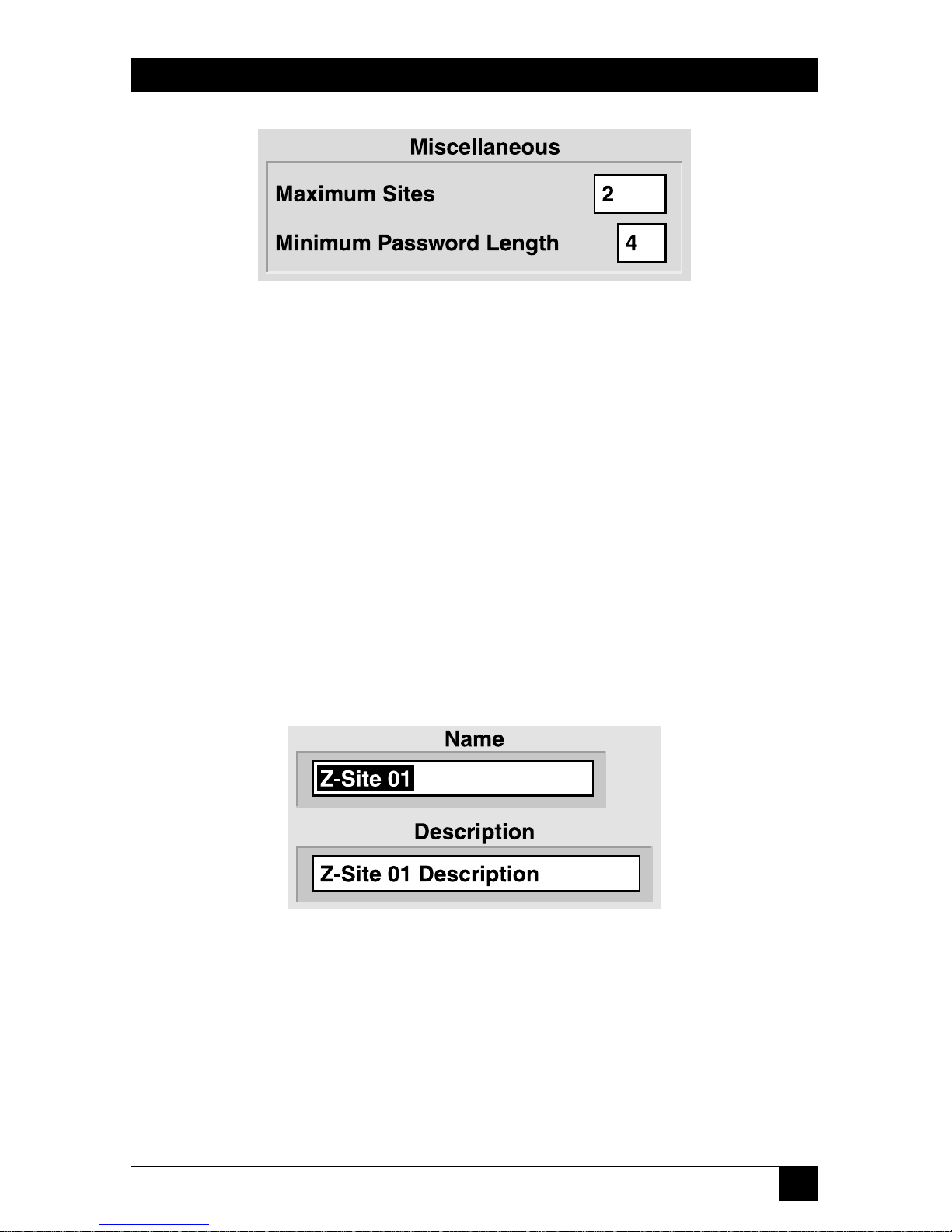
59
CHAPTER 9: Configuration Menus
Figure 9-7. Miscellaneous pane.
You can set two options in the Miscellaneous pane:
Pro Switching System II software can support up to twenty physical locations
(sites). However, performance can be optimized by setting the figure in the
“Maximum Sites” box to the number of sites that actually exist within the
supported network.
The “Minimum Password Length” (in characters) affects all passwords defined after
this entry is made.
9.2 Site Configuration
Select “Site” from the Configuration Menu to define the characteristics of any
particular site. The Site Configuration window consists of panes dedicated to
various options.
Figure 9-8. Site Name and Description pane.
The site name and site description are free-form text boxes that allow usermeaningful information for each site.
Page 61

60
PRO SWITCHING SYSTEM II WITH MANAGEMENT SOFTWARE
Figure 9-9. Site Number pane.
The site number can NOT be changed by the Pro Switching System II user. This
number is manually set at the site’s master rack. Make sure that the master rack at
this site is configured to match this number.
Figure 9-10. Discovery pane.
The “Discovery:Configured” check box is a flag indicating (to the console) that the
site exists. If a site is not configured, the console will not recognize the site nor any
racks and/or circuits at that site. If a site is “configured” after having been
“unconfigured” (this checkbox turned on after being off), all racks at that site and
all circuits within those racks will be automatically “discovered” and configured.
Figure 9-11. Communication Parameters pane.
Use the “Communication Parameters” pane to set several serial-link options.
The “Serial Port” must be either a specific PC serial port or “Next Free” (for dial
connections only). If “Next Free” is chosen, the Pro Switching System II will select
an available port from the “First/Last Automatically Assigned Port” range when a
connection to a remote location is necessary.
Page 62

61
The Pro Switching System II supports remote-site connections through either dial
modems or X.25 PADs. If modems are used, they must be capable of accepting
Hayes commands and they must be configured for “direct” asynchronous mode
(no compression, no buffering, and no protocol). X-ON/X-OFF flow control must
be selected.
The “baud rate” (data rate) must match the rate configured for the master rack at
the site (see Section 3.4) and must match the setting for the modems (or X.25
PADs) that will be used to support the link.
Check the “Dial Link” box if and only if this site is supported by dial modems or
X.25 PADs.
Figure 9-12. Retry Logic pane.
Use the “Retry Logic” pane to set how the PSSII handles retries.
“Communication Attempts” is the number of attempts by Pro Switching System II
to send an error-free message to a remote site (we recommend three). The
“Timeout Between Attempts” is the length of the pause between these message
attempts (we recommend six seconds).
After unsuccessful transmission of the specified number of attempts using a dial or
X.25 link, Pro Switching System II will disconnect (hang up) the link. The
“Reconnect” time is the “wait time” before the site is redialed and the attempts
repeated. On a dedicated (non-dial) link, “Reconnect” is the wait time before the
attempts are repeated.
CHAPTER 9: Configuration Menus
Page 63

62
PRO SWITCHING SYSTEM II WITH MANAGEMENT SOFTWARE
Figure 9-13. Miscellaneous pane.
Use the “Miscellaneous” pane to set various options.
Remote Unlock Key: The “Remote Unlock Key” is the password number that can
be used to manually unlock any rack at this site. It provides a benefit if local
switching functions are necessary during the time that a malfunction is preventing
the Pro Switching System II from controlling the racks. A “000” entry disables
manual unlocking capability.
To manually unlock a rack, press Lamp Test at the bottom of the control module
until the upper LED display indicates “PAS” (approximately five seconds). The
lower LED display will indicate a “0” at the left side. Press the right button as
required until the left digit matches the first password number. Press the left
button to access the center digit and repeat for the second password number.
Repeat this again for the right digit and the third number. When the correct
number is displayed, press the left button to unlock the rack and enable all
switching and configuration buttons.
After manual unlocking, a rack can be manually relocked by pressing Lamp Test
for approximately five seconds (both LED displays will flash “888”).
NOTE
If the rack’s configuration-setup buttons (on the control module) have
been operated, do NOT manually lock the rack until successful Pro
Switching System II access can be confirmed (a Pro Switching System II
lock command is recommended). If you lock the rack and discover that
the PSSII can’t access it, you’ll have to erase the control module’s RAM
as described in Chapter 13.
Page 64

63
CHAPTER 9: Configuration Menus
After manual unlocking followed by five minutes of “unlock time,” the rack will
automatically lock, but this automatic relocking will be disabled if the rack’s
configuration setup buttons have been operated. In that case, the rack can be
relocked only via Pro Switching System II command.
Maximum Racks: Pro Switching System II can support 100 racks at an individual
site. However, performance can be optimized by setting the “Maximum Racks”
entry in the Site Configuration to the quantity of racks that actually exist at the site.
NOTE
The “Maximum Racks” assumes that there are no “gaps” in the site’s
slave numbers. For example, if a site physically includes only a master
#00 and a slave #07, the “Maximum Racks” entry MUST be eight or
greater.
Polling Interval: When Pro Switching System II has not communicated with a site
for a significant period of time, it will connect to that site and transmit an “Are You
There” message to confirm the integrity of the management link. This period of
time is the “Wake Up Interval.”
Minimum OnLine: When there has been an automatic connection via a dial or
X.25 link, Pro Switching System II will keep the connection up for the “Minimum
On-Line” time to allow the user to investigate the cause for the automatic
connection. The link will be kept up indefinitely if the user is in the appropriate
Site View or a view of a rack or circuit within that site.
Figure 9-14. Standard buttons.
A standard site configuration, initially set to factory defaults, can be “pasted” into
any site with the “Paste Standard” button. The “Make Standard” button defines this
site’s configuration as the standard. (You should note that this doesn’t codify the
existing settings as the standard configuration, but rather whatever settings are
configured for this site—both now and in the future. If the site configuration is
subsequently changed, the standard will be automatically changed as well.)
The standard site configuration does not include the site’s dial strings (which can
also be defined as a standard). However, it is typically in your best interests to
assign both standards to the same site.
Page 65

64
PRO SWITCHING SYSTEM II WITH MANAGEMENT SOFTWARE
Figure 9-15. Configure Dial Strings button.
Pro Switching System II supports remote site connections via either dial modems
or X.25 PADs. If modems are used, they must be capable of accepting Hayes
commands and they must be configured for “Direct” asynchronous mode (no
compression, no buffering and no protocol). X-ON/X-OFF flow control must be
selected. The same data rate must be used for the Pro Switching System II comm
port, the remote master rack, and both modems.
Outgoing calls (from the Pro Switching System II) are sent via either a specific
serial port and modem (or PAD) or to an automatically selected port from the
“First/Last Automatically Assigned Port” range defined in the Enterprise
Configuration menu. Incoming calls (to Pro Switching System II) are made to
either a specific modem (and PC serial port) or to the first available port as
determined by a telco-supplied “hunt group.” Although there is no required
relationship between the outgoing automatically assigned ports and the incoming
hunt group, you are advised to make the hunt group a subset of the outgoing ports
(or the full range of outgoing ports).
Press the Configure Dial Strings button to access the Dial-String Configuration
window. It consists of the panes shown below and on the following pages.
Figure 9-16. PSSII Dial Strings pane.
The Pro Switching System includes provision for four sequential dial/response
strings for console-initiated dial connections (although many systems will require
only one combination).
Dial string #1 is first sent to the appropriate PC serial port and modem (or PAD). If
and when the correct response is received by the Pro Switching System II, dial
string #2 (if it exists) will be sent, followed by #3 and #4. If no response is received
Page 66

65
after sending any specific command, it will be repeated after expiration of the
indicated “Time-out.” If the specified number of “Attempts” has been made with
no response, the subsequent dial strings will not be sent and the Pro Switching
System II will report a system-alarm condition.
Modem example:
Command Response Timeout Attempts
1 ATDT12155551212\M CONNECT 9600 45 3
X.25 PAD example:
Command Response Timeout Attempts
1 clr\M hello 4 3
2 address*port \M com 4 3
Figure 9-17. Hang Up Strings pane.
The Pro Switching System II includes provision for two sequential hangup/
response strings (although many systems will require only one combination).
Hangup string #1 is first sent to the appropriate PC serial port and modem (or
PAD). If and when the correct response is received by the Pro Switching System II,
hangup string #2 (if it exists) will be sent. If no response is received after sending
any specific command, it will be repeated after expiration of the indicated
“Timeout.”
If the number of “Attempts” has been made with no response, the subsequent
hangup strings will not be sent and Pro Switching System II will report a systemalarm condition.
NOTE
The remote site CANNOT command a call termination.
Modem example:
Command Response Timeout Attempts
1 +++ OK 3 3
2 ATH\M OK 45 3
CHAPTER 9: Configuration Menus
Page 67

66
PRO SWITCHING SYSTEM II WITH MANAGEMENT SOFTWARE
X.25 PAD example:
Command Response Timeout Attempt
1 \P\P clr\M hello 4 3
Figure 9-18. Remote (Master Rack) Dial Strings pane.
The remote-site firmware includes provision for three sequential hangup/response
strings (although many systems will require only one combination).
Remote dial string #1 is first sent to the appropriate PC serial port and modem (or
PAD). If and when the correct response is received, remote dial string #2 (if it
exists) will be sent, followed by #3. If no response is received after sending any
specific command, it will be repeated after expiration of the indicated “Timeout.”
This sequence will be repeated indefinitely until the correct response is eventually
received.
When the last user-entered response string is satisfied, the remote site
automatically sends a fourth, system-generated “dial string.” Because this string is
sent after the connection has been established, the link treats the string as data and
delivers it to the console, which enables the console to confirm that the incoming
call came from a valid site. The console, in turn, generates a response (also treated
as data), which enables the rack to confirm that it is connected to the correct
console.
Modem example:
Command Response Timeout
1 ATDT12155551212\M CONNECT 9600 180
X.25 PAD example:
Command Response Timeout
1 clr\M hello 180
2 address*port \M com
Page 68

67
Figure 9-19. Remote Call Cleared String field.
If the remote master rack receives the “Remote Call Cleared” string, it will
recognize that the dial connection has been terminated for reasons beyond its
control. This message is typically “No Carrier” for modem connections and
“Cleared” for X.25 connections.
Figure 9-20. PSSII Call Cleared String field.
If the Pro Switching System II console receives the “PSSII Call Cleared” string, it
will recognize that the dial connection has been terminated for reasons beyond its
control. This message is typically “No Carrier” for modem connections and
“Cleared” for X.25 connections.
Figure 9-21. Standard buttons.
A standard dial configuration, initially set to factory defaults, can be “pasted” into
any site with the “Paste Standard” button. The “Make Standard” button defines this
site’s dial parameters as the standard. (You should note that this doesn’t codify the
existing dial settings as the standard configuration, but rather whatever dial settings
are configured for this site—both now and in the future. If the site’s dial
parameters are subsequently changed, the standard will be automatically changed
as well.)
The standard dial-string configuration does not include the site configuration itself
(which can also be defined as a standard). However, it is typically in your best
interests to assign both standards to the same site.
CHAPTER 9: Configuration Menus
Page 69

68
PRO SWITCHING SYSTEM II WITH MANAGEMENT SOFTWARE
H
AYES
C
OMMANDS
Hayes commands almost always begin with the “AT” (attention) characters and
end with a carriage-return character. The characters following the “AT” determine
the action(s) that the modem will perform when it receives the carriage return.
Printable characters (such as “A” and “T”) are entered via normal keystrokes.
Control characters are entered with a backslash followed by an appropriate
printable character (please refer to an ASCII code chart). For example:
“\M” sends a carriage return to the modem
“\J” sends a line feed to the modem
“\\” sends a single backslash to the modem
“T” is the Hayes “Tone” (DTMF) command. “D” is the “Dial” command. The
following command string will cause a modem to use tones to dial 1-215-555-1212:
ATDT12155551212\M
A typical response to this string is “CONNECT”.
W
HYUNCONFIGURE
?
The Pro Switching System II system has been designed to ensure that the console
acknowledges the existence of all circuits and racks that exist within a site. If a
circuit or rack is physically removed, that removal is considered to be a system
anomaly and the user is informed with color-coded bars and question marks.
“Unconfigure” (removing the check mark in “Discovery:Configured”) should be
performed when a system component, such as a circuit or a rack, has been
deliberately removed and you want to prevent the display of the “anomaly.”
Circuits and slave racks can be deliberately unconfigured after physical removal
from the system.
However, if a master rack is unconfigured (under any circumstances), the entire
site is unconfigured.
When a site (or master rack) is unconfigured, the Pro Switching System II will
cease polling that site regardless of whether it is physically present or not. If a
circuit or slave rack is unconfigured without having been physically removed, the
system will rediscover the unconfigured item.
Page 70

69
CHAPTER 9: Configuration Menus
9.3 Rack Configuration
Select “Rack” from the Configuration Menu to define the characteristics of any
particular rack. In the window that appears, the rack name and description are
free-form text boxes that allow user-meaningful information for each rack. This
rack must be physically located at the indicated site and must be configured for the
indicated rack number.
The “Discovery:Configured” check box is a flag indicating (to the console) that the
rack exists. All racks that physically exist (and are connected) will be “discovered”
and automatically configured when the Pro Switching System II is powered up. If a
rack has been deliberately “unconfigured” (check removed), all circuits within that
rack will also be unconfigured. See “Why Unconfigure?” on the previous page.
9.4 Circuit Configuration
Select “Circuit” from the Configuration Menu to define the characteristics of each
individual Pro Switching System II-supported circuit. Except as noted, these
characteristics are for user information only (they are displayed on the Circuit
View screen) and do not affect Pro Switching System II operation.
The Circuit Configuration window consists of panes dedicated to various options.
The circuit name and description are free-form text boxes that allow usermeaningful information for each site. If the user circuit is synchronous, the entries
in the “Communications Parameters” list boxes are entirely for your convenience.
Free-form text boxes are also available for a name and description of each
individual interface (or “side”) of the circuit. There are three “sides” to a switching
circuit: the “Common,” an “A,” and a “B.” The “Common” is set by the user as
“DTE” or “DCE” and the “A” and “B” sides will be the opposite. In the case of a
non-switching circuit, the Pro Switching System II assumes “DTE” and “DCE” to be
as marked on the physical rack connectors.
Figure 9-22. Discovery:Configured checkbox.
The “Discovery:Configured” checkbox is a flag indicating (to the console) that the
circuit exists. When a Site is initially configured, all Racks within that Site and all
Circuits within those Racks are automatically discovered (and “configured”). Also
see “Why Unconfigure?” on the previous page.
Page 71

70
PRO SWITCHING SYSTEM II WITH MANAGEMENT SOFTWARE
Figure 9-23. Site/Rack/Slot pane.
The “Site/Rack/Slot” pane allows no entries. It displays the user-defined names for
the site and rack containing the circuit being configured and the number of the
circuit’s physical card slot within the rack. Refer to Sections 9.2 and 9.3.
Figure 9-24. Circuit Type field.
The “Circuit Type” field reports the interface signaling for the circuit being
configured, which is autodetected by the PSSII. It is possible to scroll between
different interfaces, but the system will not let you select an incompatible interface.
NOTE
Module versions are available with PROMs dedicated to a particular
signaling standard which will cause the circuit to default to that
standard when Pro Switching System II is restarted. Also, the circuit
type is automatically detected.
Figure 9-25. Alarm Template list box.
The “Alarm Template” list box allows you to select a particular “alarm template”
(see Section 9.7) that Pro Switching System II will use to continuously monitor the
proper operation of this circuit.
Page 72

71
Figure 9-26. Group list box (Group A shown).
Use the “Group A,” “Group B,” and “Group C” list boxes to determine the groups
(if any) to which this circuit will belong (see Section 9.5). Each individual circuit
can belong to as many as three groups but need not belong to any. Pull down the
list boxes to select any of the user-defined groups (there can be as many as 63 of
these).
All circuits in any specific group can be viewed in the Group View. Also, in the case
of switching products, an entire group can be switched at one time (either via
command or automatically upon alarm). There is no requirement that all circuits
within a group be at the same site.
Figure 9-27. Standard buttons.
A standard circuit configuration, initially set to factory defaults, can be “pasted”
into any circuit with the “Paste Standard” button. The “Make Standard” button
defines this circuit’s parameters as the standard. (You should note that this doesn’t
codify the existing circuit settings as the standard configuration, but rather whatever
settings are configured for this circuit—both now and in the future. If the circuit’s
parameters are subsequently changed, the standard will be automatically changed
as well.)
CHAPTER 9: Configuration Menus
Page 73

72
PRO SWITCHING SYSTEM II WITH MANAGEMENT SOFTWARE
9.5 Group Configuration
Select “Group” from the Configuration Menu to define switching groups. In the
Group Configuration window, you can customize group names and descriptions.
(Group membership is determined using the Circuit Configuration window—see
Section 9.4). You can also configure automatic (time of day) switching for all
members of the group.
Figure 9-28. Enable checkboxes and Switch To list boxes.
The “Enable” check box enables a particular switching action for all members of
the group. Up to eight enables are available for eight switching actions and/or
times of the day and/or days of the week and/or days of the year. (In the example
in Figure 9-29, all switches within the group will reverse their current positions at
2:10 p.m. every Tuesday, every Wednesday, every Saturday and every August 15.)
The “Switch to” list boxes allow you to select “Alternate” (switch to A if on B or to B
if on A), “Force-A” (switch to A), or “Force-B” (switch to B).
Figure 9-29. Sample switch-timing configuration for a group.
Page 74

73
CHAPTER 9: Configuration Menus
9.6 User Configuration
Select “User” from the Configuration Menu to enter user information and set
users’ access privileges. The User Configuration window consists of an Info pane
and a Security pane.
Figure 9-30. Info pane.
In the info pane, the “ID” and “Password” entries are required for logon purposes.
Each individual user can change his or her own password during a subsequent
logon.
NOTE
A user with “Administration” access can change another user’s
password without knowing its current setting.
The “Enabled” checkbox must be checked for Pro Switching System II to accept
this user’s logon sequence. All enabled users can log on and off, have access to all
Pro Switching System II “View” screens, and can shut down (Quit) the Pro
Switching System II from the “Utilities” menu. Other capabilities are determined
by the “Security” check marks (see the following paragraphs).
The “User Name” is the user’s real name.
Page 75

74
PRO SWITCHING SYSTEM II WITH MANAGEMENT SOFTWARE
Figure 9-31. Security pane.
In addition to “View access,” the Security pane’s checkboxes provide the following:
“Test Access” privileges allow you to establish test connections and to enable,
acknowledge, and clear alarms.
“Switch Access” privileges allow you to switch circuits and to lock and unlock racks.
“Configure Access” privileges allow you to configure any aspect of the Pro
Switching System II system except “Enterprise” and “Users.” “Utilities:Database”
access is also excluded from this security level.
“Administration” privileges allow you to configure the “Enterprise” and “Users”
and also permit access to the “Database” portion of the “Utilities” menu to purge
or initialize the Pro Switching System II database.
CAUTION!
It is possible to delete the Administration access privileges from the
presently logged-on user. If the system is logged off while no users with
Administration privileges remain, Administration authorization cannot
be retrieved without calling Technical Support.
Page 76

75
9.7 Alarm-Template Configuration
Select “Alarm Template” from the Configuration Menu to define alarm
“templates.” which can then be assigned to specific circuit(s) using the Circuit
Configuration menu (see Section 9.4). The actual creation of an alarm template is
performed by modifying one of the ninety-nine default templates provided with
Pro Switching System II. The names for the default templates have a “Z” prefix.
Figure 9-32. Alarm template.
In the Alarm Template window, the default template name can be changed with
normal text-editing keystrokes in the “Name” field. Names should be chosen that
have meaning relative to the expected use of the associated alarm.
Each template can have up to eight “triggers.” Each trigger is a separate alarm
condition and is individually enabled (checked) by a mouse click on its enable
box. For each “trigger” within an Alarm template, the alarm-detection mechanism
independently interprets signal levels of a specific lead as follows:
• Control signals (RTS, CTS, DCD, or DTR) ON (high) or OFF (low)
• Clock signals (SCR or SCT) PRESENT (transitions) or ABSENT (no
transitions)
• Data signals (RD or SD) ACTIVE (zeroes/spaces) or IDLE (ones/marks)
The Alarm and Clear timers must be set for each enabled “trigger” (alarm
condition) in an alarm template. Minimum times (for both alarm and clear) are:
• Control signals, 1 second
• Clock signals, 2 seconds
• Data signals, 4 seconds
The maximum time to alarm is 6 hours. The “Ignore” timer is fixed at 2 seconds.
Two checkboxes are provided for each trigger in an alarm template: “A” for
audible and “V” for visual. These respectively enable audible (beep) and visual
(LED) alarm indications at the rack(s) where the alarm condition occurs.
CHAPTER 9: Configuration Menus
Page 77

76
PRO SWITCHING SYSTEM II WITH MANAGEMENT SOFTWARE
Figure 9-33. Automatic Switch and Switch To list boxes.
The alarm template’s switching entries apply only to switching circuits that the Pro
Switching System II supports.
Each alarm “trigger” within an Alarm template can be independently configured
for a specific automatic switching action. This action will take place when an alarm
condition has resulted from the conditions described in the trigger. The action
selected can be directed toward:
> None: No automatic switching.
> Circuit: Switch the alarming circuit(s) only.
> Rack: Switch all circuits in the physical rack(s) containing the alarming
circuit(s).
> Group: Switch all circuits within a selected group. This group will typically
include the alarming circuit, but that is not a requirement.
The switching action itself can be:
> Alternate: Reverse the existing switch position(s).
> “A”: Force the switch(es) to the “A” position.
> “B”: Force the switch(es) to the “B” position.
Figure 9-34. Standard buttons.
A standard circuit configuration, initially set to factory defaults, can be “pasted”
into any circuit with the “Paste Standard” button. The “Make Standard” button
defines this circuit’s parameters as the standard. (You should note that this doesn’t
codify the existing circuit settings as the standard configuration, but rather whatever
settings are configured for this circuit—both now and in the future. If the circuit’s
parameters are subsequently changed, the standard will be automatically changed
as well.)
Page 78

77
CHAPTER 10: Security Menus
10. Security Menus
Figure 10-1. Security menu.
10.1 Log Out
Logs the user out of the Pro Switching System II without shutting down the
software.
10.2 Change Password
Allows the logged-on user to change his or her own password.
Page 79

78
PRO SWITCHING SYSTEM II WITH MANAGEMENT SOFTWARE
11. Reports Menu
Figure 11-1. Reports menu.
The Reports Menu allows Event, Alarm, and Configuration reports to be printed to
the console screen, a text file, or a printer. In order to view or print properly, a
specific printer must be selected in landscape mode through the operating system.
Reports can be generated from either the permanent Event Log or the permanent
Alarm Log with user-determined filtering at the time the report is selected. All
permanent records of events and alarms that haven’t been purged (see
Section 12.1) are available for a “Report,” including those that were lost or
discarded from the temporary log files (see Chapter 8).
11.1 Alarm Range
Alarm Range allows you to select the “from/to” range of alarms stored on disk.
The “Anomalies Only” check box will filter out all alarm clears. Also see
Section 12.7.
11.2 Event Range
Event Range allows you to select the “from/to” range of events stored on disk. The
“Anomalies Only” check box causes the Pro Switching System II to filter out all
normal system events and to display/print only “anomalies.” An event anomaly is a
major event that would have displayed a maroon bar at the bottom of all Pro
Switching System II displays. Also see Section 11.7.
Page 80

79
11.3 Configuration
Configuration allows you to print a report of the current configuration of Sites,
Racks, Circuits, or Users. Three types of “Circuits” reports are available: “Circuits,”
“Protocol,” and “Circuits in Large Print.”
• The basic “Circuits” report displays/prints the name of each circuit with
descriptions of the circuit itself and the DTE/DCE “sides” of the circuit.
• The “Protocol” report displays/prints the name of each circuit with its
protocol, speed (data rate), clock configuration, data code, parity, stop bit
configuration, and rack identification.
• The “Circuits in Large Print” report uses a large, more readable font. The
report resembles the basic “Circuits” report except that Primary Group
assignment is added while abbreviated descriptions are provided for the
DTE/DCE “sides” of the circuit.
11.4 All Alarms
All Alarms provides a report of all alarms stored on disk. No filtering is applied.
11.5 All Events
All Events provides a report of all events stored on disk. No filtering is applied.
CHAPTER 11: Reports Menu
Page 81

80
PRO SWITCHING SYSTEM II WITH MANAGEMENT SOFTWARE
11.6 Report-Display and Report-Printing Controls
The scroll bars on the right side of the screen function within the single displayed
report page. Icon mouse clicks are used for page selection and print control:
Displays the first page of the report.
Displays the preceding page of the report.
Displays the following page of the report.
Displays the last page of the report.
Stops further loading of alarms or events into the selected report.
Prints the displayed report using the printer identified by the Print
Manager.
Page 82

81
12. Utilities Menu
Figure 12-1. Utilities menu.
12.1 Database
Upon entering the Database portion of the Utilities menu you are presented with
choices to completely or partially purge the permanent logs, back up or restore the
configuration database, or initialize the database.
Figure 12-2. The Complete Log Purges pane.
By clicking the appropriate button in the Complete Log Purges pane, the Alarm
and/or Event Logs can be completely purged to save disk space. These logs are not
the temporary log files accessed under the “Logs” menu (see Chapter 8) but,
rather, the complete logs accessed under the “Reports” menu. Before purging
either or both of these logs, make sure that their contents are not required for a
trouble history.
CHAPTER 12: Utilities Menu
Page 83

82
PRO SWITCHING SYSTEM II WITH MANAGEMENT SOFTWARE
Figure 12-3. The Partial Log Purges pane.
If, rather than purging an entire permanent log, you’d like to purge just older
records, you can specify a start date and click the appropriate button in the Partial
Log Purges pane to purge all entries in the permanent Alarm and/or Event Logs
that were recorded before that date.
Figure 12-4. The Configuration pane.
The entire configuration database can be backed up and restored manually using
the buttons and the TO/FROM field in the Configuration pane. The size of the
backup files precludes using floppies for this purpose; send backups to a LAN server.
CAUTION!
If automatic backup has been configured in the Enterprise Configuration
screen, and manual backups are made to the same location, they will
overwrite each other.
Page 84

83
CHAPTER 12: Utilities Menu
Figure 12-5. The Initialize Database button.
You can initialize the PSSII’s entire configuration database by clicking the
“Initialize Database” button. Initializing the database will return the Pro Switching
System II to its factory-default configuration. ALL user-entered parameters will be
lost. We strongly recommend that you back up the current database before taking
this action.
12.2 Quit
The Pro Switching System II will shut down when this menu item is selected.
NOTE
The temporary log files available under the Logs Menu (see Chapter 8)
will be lost when the Pro Switching System II shuts down.
Page 85

84
PRO SWITCHING SYSTEM II WITH MANAGEMENT SOFTWARE
13. Erasing Control-Module RAM
If a control/test module was accidentally locked while not connected to the
control console, you’ll have to use the following procedure to unlock the control
module:
1. Power down the rack by disconnecting it from its power source.
2. Remove the control/test module (See Section 2.2.2).
3. Remove the RAM chip from position U25 (see Figure 13-1) on the
control/test module.
CAUTION!
Removing the RAM chip erases all configurations and settings.
Figure 13-1. Position of the RAM chip on the control/test module.
RAM (U25)
Page 86

85
CHAPTER 14: Troubleshooting
14. Troubleshooting
14.1 Calling Black Box
If you determine that your Pro Switching System II is malfunctioning, do not attempt
to alter or repair it. It contains no user-serviceable parts. Contact Black Box Technical
Support at 724-746-5500.
Before you do, make a record of the history of the problem. We will be able to
provide more efficient and accurate assistance if you have a complete description,
including:
• the nature and duration of the problem;
• when the problem occurs;
• the configuration of your system;
• the components involved in the problem—cables, devices, etc.;
• any particular application that, when used, appears to create the problem or
make it worse; and
• the results of any testing you’ve already done.
14.2 Shipping and Packaging
If you need to transport or ship your Pro Switching System II:
• Package it carefully. We recommend that you use the original container.
• Before you ship the PSSII back to Black Box for repair or return, contact us to
get a Return Authorization (RA) number.
Page 87

86
PRO SWITCHING SYSTEM II WITH MANAGEMENT SOFTWARE
Glossary
Alarm: An alarm is a customer-defined occurrence on any circuit within the entire
network. An alarm can be the presence or absence of data, clock, or control
signaling. Although alarms are normally defined as undesirable interface
anomalies, that is not a requirement. Also see Alarm Timers.
Alarm Timers:
• Time to Alarm: When an alarm condition occurs, the Pro Switching System II
will confirm that the condition is present for the “Time to Alarm” before it
recognizes that alarm and takes appropriate action.
• Time to Clear: When an alarm has been recognized and the alarm condition
subsequently clears, it must remain clear for the “Time to Clear” before the
Pro Switching System II recognizes the clear condition and takes appropriate
action.
• Time to Ignore: When an alarm occurrence on a particular switchable circuit
results in an autoswitch, all potential alarm and clear conditions on that line
will be ignored for the duration of the “Time to Ignore.”
ARQ: Automatic Repeat reQuest. An error-control mechanism with which the
receiver circuitry can determine whether or not a received transmission is totally
error-free. If it is not, a repeat of the transmission is automatically requested. ARQ
is the most efficient form of error control on commonly available long-haul
transmission facilities. In comparison with FEC, ARQ results in significant delays
when errors are present and large amounts of errors can completely halt the
successful transmission of valid user data.
ASCII: American Standard Code for Information Interchange. An asynchronous
signaling code with character framing. An ASCII character consists of a start bit,
seven data bits, a parity bit (even if unused), and a stop bit. In some cases, 1, 1
1
⁄
2, or
2 stop bits are used. Thus, ASCII is at best 70% efficient with seven data bits out of
every ten-bit character. Note that 1
1
⁄
2 stop bits can not be used if the data will be
carried by modern-day modems. Also see Parity and Asynchronous.
The parity bit is used as an eighth data bit with International ASCII and
Extended ASCII, thus increasing the number of definable characters from 128 to
256.
ASCII data can also be transported synchronously and, in such cases, it is
commonly known by the oxymoron “clocked async.”
Page 88

87
GLOSSARY
Asynchronous: Asynchronous (async) data transmission does not use clock
signaling between the DTE and DCE. Characters are individually framed by start
and stop bits. The most common async character code is ASCII. True async DCEs
can accept any DTE data rate up to a defined maximum.
Isochronous data transmission also does not use clock signaling between the
DTE and DCE. However, isochronous DCEs will accept only specifically identified
DTE data rates. As a practical matter, modern-day “async” DCEs are actually
isochronous. Exceptions are modems supporting no more than 300 bps and the
obsolete 1200-bps 202-type modem. Note that isochronous modems cannot
accommodate a 1
1
⁄
2
-stop-bit coding.
Balanced Signals: Balanced signals are those that require two wires per signal, an
“A” wire and a “B” wire. Examples are V.35 clock and data leads and RS-530/449/
422 clock, data, and control leads.
This contrasts with unbalanced signals, which are those that use a single wire per
signal plus a common ground shared with other signals. Examples are V.35 control
leads and RS232 clock, data, and control leads.
Breakout Box: A basic communications tester that provides the instantaneous
status of the leads in an interface.
Circuit: A pair of connected complementary (DCE/DTE) interfaces. In the case of
a Pro Switching System II, an example of a circuit is a common DCE connected to
either DTE-A or DTE-B.
Two (or more) circuits in a series are commonly treated as a single larger circuit.
Compression: A mechanism that allows a significantly large amount of data to be
represented by a relatively small amount for storage and/or transmission. Data is
not usable in its compressed form; it must be uncompressed (returned to its
original form) before use. Files can be compressed offline in a computer or in real
time by a modem but not both (a compressed file cannot be compressed a second
time).
Modems incorporating a modified FEC with Trellis Coded Modulation (TCM)
typically include real-time compression.
Configured/Unconfigured: System components (sites, racks, and circuits) must be
“configured” in order to be recognized by the Pro Switching System II software.
Components are configured automatically and with checkboxes in the appropriate
configuration menus. They are unconfigured by removal of the check mark. The
Pro Switching System II will deny the existence of any components that are not
configured.
Page 89

88
PRO SWITCHING SYSTEM II WITH MANAGEMENT SOFTWARE
CSU: Channel Service Unit. Connects a DSU or a bipolar DTE to digital common
carrier networks such as DDS. Contains the last signal regenerator on the digital
line and a mechanism to put the line into loopback for testing from the carrier’s
central office.
Data: Any representation such as bits, characters, or analog quantities to which
meaning is, or might be, assigned.
DCE: Data Communications Equipment. The “side” of an interface closer to the
common carrier network. Also known as “Service.” See Interface.
DDCMP: DEC’s Digital Data Communications Message Protocol. A generalpurpose byte-oriented data-link protocol designed for inter-computer data
communications. DDCMP operates over synchronous or asynchronous and
switched or non-switched communications links. It can operate in point-to-point
configurations or in multipoint configurations in which communication takes
place between a control station and each of several tributary stations. Incoming bits
are assembled into bytes (characters) with start/stop bits for async endpoints and
data blocks with synchronization characters (or sequences) for sync endpoints.
DDD and PSTN: DDD and PSTN are terms for the dial network commonly used
for voice-telephone calls and by dial modems. DDD is “Direct Distance Dial” and
PSTN is “Public Switched Telephone Network.” The dial network is universally
“2-wire.”
DDS: Dataphone Digital Service, formerly Digital Data Service. A digital network
service available from AT&T, the Bell Operating Companies, and independent
telephone companies. Non-switched synchronous data rates of 2400, 4800, 9600,
and 56,000 bps (bits per second) and switched synchronous 56,000 bps are
commonly available. Also, some operating companies offer 19,200 bps and some
offer reverse channel capability. A DSU and a CSU are used in place of a modem,
although some 56,000-bps DTEs use bipolar signaling and require only a CSU.
DSU: Data Service Unit. A DCE used in place of a modem with common carrier
digital networks. Frequently (but incorrectly) referred to as a “digital modem.” The
DSU converts common data-processing signals, such as those used in RS-232, V.35,
and RS-422, to the digital network’s bipolar format. The DSU is not needed if the
attached DTE uses bipolar signaling. Connects to the network through a CSU.
DTE: Data Terminal Equipment. The “side” of an interface closer to the data
processing equipment. Also known as “Equipment.” See Interface.
Page 90

89
GLOSSARY
EBCDIC: Extended Binary Coded Decimal Interchange Code. A synchronous
signaling code, commonly used by IBM, with no character framing (start/stop) bits
and no parity bit. An EBCDIC character consists of eight data bits. It is used as one
of many contiguous characters within a large block. The block contains start- and
stop-bit sequences and an error-control bit sequence. Also see Synchronous.
Echo: Async terminals use an “echo” to display entered characters on the screen.
The echo can be remote (provided by the host computer) or local (within the
terminal). A remote echo requires a full-duplex transmission facility while a local
echo does not. Consequently, many terminals use the “FDX” terminology to
configure for remote echo and the “HDX” terminology to configure for local echo.
Failure to configure the host to complement the terminal will result in either no
screen display (no echo) or double characters (two echoes).
Enterprise: The sum total of all network components managed by the Pro
Switching System II.
Error Measurements:
• Bit Error Rate (BER) is, simply, the ratio of errored bits received to total bits
received during the receipt of a known repeating pattern. The Pro Switching
System II generates and detects two standard pseudo-random patterns, 511 bits
and 2047 bits, plus All Marks, All Spaces, and Alternate Mark/Space. A BER
Test is also known as a BERT.
• Block Error Rate (BKER) is similar to BER except that groups of contiguous
bits are artificially defined as “blocks.” Block sizes are sometimes related to the
transmitted pseudo-random pattern size, but a 1000-bit block size is also
common. An “errored block” is a block that contains at least one bit error.
BKER is more meaningful than BER for analog facilities used with sync
error-control protocols. A BKER Test is also known as a BLERT.
• Error-Free Seconds (EFS) is the quantity of error-free seconds expressed as a
percentage of the total quantity of seconds of the test. EFS is more meaningful
than BER and BKER for digital (DDS) facilities.
• Also see Interactive Testing.
FEC: Forward Error Control. An error control mechanism in which the receiver
circuitry can determine the presence of errors in a received transmission and can
correct those errors without requesting additional information from the
transmitting circuitry. In comparison with ARQ, FEC consumes large amounts of
bandwidth regardless of the presence of errors.
Trellis Coded Modulation (TCM, used with 19,200- and 38,400-bps modems)
includes a modified FEC to bring the perceived performance to a level that can be
handled efficiently by common EDP ARQ protocols. A 19,200-bps modem can
Page 91

90
PRO SWITCHING SYSTEM II WITH MANAGEMENT SOFTWARE
nominally transmit 1920 ASCII cps (characters per second). However, that figure
includes the 20% overhead required for the modified FEC. Thus, under the best of
circumstances, a 19,200-bps modem can transmit 1536 ASCII cps.
If data compression is enabled (common with TCM modems), the 1536 cps
figure can represent a substantially greater quantity of actual user cps. Note that
the modem’s compression mechanism provides no benefit if the user data has
been previously compressed by the computer.
Full-Duplex: Also known as “FDX” and “Duplex.” See Half-Duplex, Simplex, and
Echo.
1. The ability of a transmission facility to transport data in both directions
simultaneously. Modems (or DSUs) at both ends of point-to-point full-duplex
facilities and at the master location in multipoint full-duplex facilities use
“constant carrier.” Modems at remote locations in multipoint full-duplex
facilities use “controlled carrier” (carrier controlled by RTS with data
transmission controlled by CTS).
2. The ability of a data-processing device or protocol to simultaneously transmit
and receive data.
NOTE
Some devices and protocols (for example, BiSync) require full-duplex
facilities but actually operate in half-duplex.
Group: A “group” is a logical collection of circuits without regard to their location
within the Pro Switching System II. All switchable circuits within a specific group
can be switched by either console command or automatically (upon alarm). There
is no requirement that the alarming circuit belong to the group that will be
automatically switched. A circuit need not belong to a group, but, if it does, it can
belong to one, two, or three groups. Circuits are assigned to and removed from
groups by using the Circuit Configuration menu (see Section 9.4).
The Group View screen provides detailed status information regarding all
circuits within a group and allows single-command switching of all switchable
circuits within the group.
Page 92

91
Half-Duplex: Also known as “HDX.” See Full-Duplex, Simplex, and Echo.
1. The ability of a transmission facility to transport data in both directions but
not simultaneously. Half-duplex facilities use modems (or DSUs) configured
for “controlled carrier,” also known as “switched carrier,” (carrier controlled
by RTS with data transmission controlled by CTS) at all locations.
2. The ability of a data-processing device or protocol to transmit and receive
data but not simultaneously.
NOTE
Some devices and protocols (for example, BiSync) require full-duplex
facilities but actually operate in half-duplex.
High-Speed Monitoring: If “High-Speed Monitoring” is selected from any Pro
Switching System II monitor-activation menu, user data up to 2.048 Mbps can be
monitored. Because of rate limitations with RS-232 signaling, the rack must contain
the optional interactive test-module card with V.35 monitor outputs.
During the time that the high-speed monitoring is activated, all circuit-card
processing in the entire rack containing the monitored circuit will be halted. This
includes alarm reporting (and any attendant automatic switching), software
breakout-box information, and switch-position status. The circuit cards will
respond to console-generated switch commands (but without reporting the
resulting position-change information to the console). When the high-speed
monitoring is subsequently turned off, all current status will be immediately
reported to the console.
Hunt Group: The local telephone-operating company (telco) can configure
multiple dial lines at a single location as a “hunt group.” Incoming calls are always
dialed to a single number (the lowest number of the group). The telco Central
Office directs the call to the first non-busy line within that group. A hunt group
with attached modems at the Pro Switching System II site can be used to support
incoming calls from remote sites.
Interactive (I/A) bus: The Interactive (I/A) bus functions as an “all-purpose” bus
in a rack adapter. By console command, any identified circuit (or circuits) can be
disconnected and a specific interface (“A,” “B,” or “common”) connected to the
I/A bus. Thus, the bus can be used to connect an interface to the rear-mounted
I/A Test connectors or, in the case of the Pro Switching System II, to the rearmounted Monitor connectors and/or to cross-connect any two interfaces within a
rack adapter. Through appropriate external cabling, a cross-connect can be
established between two interfaces in separate rack adapters.
GLOSSARY
Page 93

92
PRO SWITCHING SYSTEM II WITH MANAGEMENT SOFTWARE
Interactive Test Module (ITM): The Interactive Test Module (ITM) is installed in
the leftmost full-height slot in a Pro Switching System II rack. It contains the system
firmware. The firmware constitutes a logical bridge between the console
commands and the circuit modules. Rear connectors support console
communications and external connections from both the interactive test bus and
the monitor test bus.
The interactive test module also contains LED signal-status indicators and
voltage-test points accessed with manual patch cabling.
Interactive Testing: “Interactive Testing” is the intrusive testing of one interface of
a circuit. Interactive testing requires the identification of both a circuit and an
interface, DTE or DCE, associated with that circuit. In the case of the Pro
Switching System II, the interface is identified as “A,” “B,” or “common.” If the
selected interface is half of a connected DCE/DTE combination, that combination
must be disconnected.
Interactive tests can consist of protocol simulation, BER tests, BKER tests, or EFS
tests. Also see Error Measurements.
Interface:
1. One “side” of a pair of connected devices; that is, the DCE side or the DTE
side.
2. The signaling specification used by a pair of connected devices. Signaling
specifications supported by the Pro Switching System II are RS-232, V.35,
X.21, RS-530/422A, and RS-449/422 (abbreviated).
Leased Line: A telephone line (nearly always 4-wire) that permanently connects
two or more customer sites. It is also called a “private line” and a “dedicated line.”
Except for the 4-wire configuration, leased lines are similar to dial lines.
Lock/Unlock: Racks can be locked and unlocked from the Pro Switching System II
console.
Switching and configuration buttons will not function on a locked rack.
However, all manual patching functions are still enabled.
The Pro Switching System II has no switching buttons and the configuration
buttons perform no function under the software. When a Pro Switching System II
rack is locked, manual patch-cord insertion will not result in circuit interruption.
Modem: A “dataset,” commonly called a “modem” (from “modulatordemodulator”), allows digital computer signaling to be transmitted over analog
telephone lines. Modems are available that are synchronous or asynchronous for
either 2-wire dial (DDD, PSTN) or 4-wire leased-line applications.
Page 94

93
Monitor bus: The Monitor bus in a Pro Switching System II rack adapter carries the
TTL representation of the signaling from any circuit identified with a console
command. This TTL signaling is then converted to RS-232 signaling by the
interactive test-module (ITM) card and presented to the rear-mounted Monitor
Test connector, thus ensuring electrical isolation in the case of an operator error at
the tester control panel. An optional ITM card converts to V.35 signaling. Any
circuit can be monitored by a single RS-232 (or V.35) monitor tester regardless of
the interface signaling of the circuit itself.
The Pro Switching System II hardware can provide monitor outputs for customer
signaling at customer data rates up to 256 kbps with no impact on system
functionality. It can support 2.048 Mbps with minor reductions in system
functionality during the time that the “High-Speed Monitoring” is activated.
The signals available for monitoring are SD, RD, RTS, CTS, DSR, DCD, DTR,
SCT, SCR, SCTE, and LL.
Monitor Testing: “Monitor Testing” is the non-intrusive monitoring of a selected
circuit and is also known as “bridged testing.”
Multipoint: A communications link connecting more than two stations in which
one station is responsible for data-link control. Also known as multidrop. See Full-
Duplex.
Overhead: Framing, error control, addressing, idle code, or any other characters
or bit sequences in a data transmission other than actual end-user data.
Parity: A character-level error-control mechanism used with asynchronous
signaling codes. A parity bit is set to either a “one” (mark) or a “zero” (space) to
ensure that the total quantity of “ones” within a character are either odd (odd
parity) or even (even parity). Start and stop bits are excluded from the parity
calculation. Character level error control has not been successful and, today, parity
is rarely used. However, asynchronous hardware requires that the parity bit be
present (usually forced to “one”) even if unused. Also see ASCII.
Point-to-Point: A communications link connecting two and only two stations. See
Full-Duplex.
Polling: Interrogation of devices for purposes such as to avoid contention, to
determine operational status, or to determine readiness to send or receive data.
Rack Adapter: A “rack adapter,” also called a “rack,” is a Pro Switching System II
chassis that is mounted in a NEMA standard 19" equipment cabinet. It contains
slots to accommodate power supplies, a control module, and sixteen circuit
modules.
GLOSSARY
Page 95

94
PRO SWITCHING SYSTEM II WITH MANAGEMENT SOFTWARE
Reverse Channel: The RS-232 specification assumes that normal transmit and
receive data (pins #2 and #3) will be at identical rates. However, the specification
also includes a full complement of secondary data and control signals (but no
clocks) for additional data transport, typically at rates from 5 to 75 bps. The need
for these secondary channels no longer exists but, when it did, a half-duplex facility
was configured to operate in a simplex manner with a secondary channel in the
opposite, or reverse, direction (hence, “reverse channel”).
The Pro Switching System II supports all reverse channel signaling.
RS-232: An electrical signaling specification published by the Electronic Industries
Association (EIA). Although not identified in the specification, the 25-pin (DB25)
connector, with specific pin assignments, is commonly accepted as “the RS-232
connector.”
The Pro Switching System II supports RS-232 on the DB25 connector with
industry-standard pin assignments.
All RS-232 signaling is unbalanced.
RS-530, RS-449, RS-422, RS-422A: RS-530, RS-449, RS-422, and RS-422A are
signaling specifications published by the Electronic Industries Association (EIA).
RS-422 defines electrical signaling characteristics. It references a companion
standard RS-449 which defines signal functions placed on a 37-pin (DB37)
mechanical connector with specific pin assignments.
Because of the cost of the DB37 connectors, manufacturers generally ignored
that portion of the specification and placed a subset of the RS-449 signals on a 25pin (DB25) connector. The EIA subsequently legitimized this practice by
publishing RS-422A/RS-530.
As a practical matter, RS-530 is simply “RS-449 on DB25.” The Pro Switching
System II supports both RS-449 and RS-530 with pin assignments that match the
specifications.
All RS-530 signaling is balanced.
SDLC: Synchronous Data Link Control. A discipline conforming to subsets of the
Advanced Data Communication Control Procedures (ADCCP) of the American
National Standards Institute (ANSI) and High-level Data Link Control (HDLC) of
the International Standards Organization (ISO) for managing synchronous, codetransparent, serial-by-bit information transfer over a link connection. Transmission
exchanges may be duplex or half-duplex over switched or non-switched lines. The
configuration of the link connection may be point-to-point, multipoint, or loop.
Page 96

95
GLOSSARY
Shared Management Links: Multiple physical sites can share Pro Switching
System II serial ports for management access through dial modems and/or X.25
PADs. The Pro Switching System II console and the remote locations will
automatically connect when necessary for management communication in either
direction. This sharing can be implemented as a cost-saving measure and is
absolutely necessary when the total number of physical sites exceeds the number of
available PC serial ports.
Simplex:
1. A transmission facility limited to transporting data in only one direction.
Simplex facilities are extremely rare. See Full-Duplex and Half-Duplex.
2. A data-processing device or protocol capable of transmitting or receiving, but
not both. Simplex devices are rare in data-processing applications. One
example is printing through the obsolete “202” modem. In dial mode, the
202 was half-duplex and printer flow control could not get back to the
computer fast enough. So the printer was configured as simplex with a reverse
channel for flow control. Simplex examples in other industries include
commercial radio and television.
Site: All hardware components (racks and circuits) accessed through a single serial
port at the Pro Switching System II PC, typically residing at one physical site or
location.
Switch/Patch Module: A switch/patch module supports one A/B switchable circuit
in the Pro Switching System. Twenty-four leads (wires) are switched; safety ground
is never disconnected. Switch/patch modules are available for RS-232, V.35, X.21,
and RS-530/RS-449 interfaces. Each Pro Switching System II chassis accommodates
sixteen switch/patch modules in any mix/match configuration.
Synchronous: Synchronous (sync) data requires the exchange of bit-rate clocking
between the DTE and DCE. Transmit Data (to the DCE) is phased to the Transmit
Clock (usually provided by the DCE). Receive Data (from the DCE) is phased to
the Receive Clock (always provided by the DCE). Sync data does not use stop/start
character framing. Instead, a large group of contiguous characters are framed by a
start-bit sequence and an end-bit sequence. The most common sync character code
is EBCDIC.
NOTE
With modern-day bit-oriented “DLC” protocols, the “large group of
contiguous characters” is treated as a very large group of sequential
bits.
Page 97

96
PRO SWITCHING SYSTEM II WITH MANAGEMENT SOFTWARE
Turnaround Time: The physical delay from the end of a transmission to receipt of
the response to that transmission. This could result from a variety of factors,
including physical distance and/or CTS delay at a remote location configured for
controlled carrier (carrier controlled by RTS with transmission controlled by CTS).
Unbalanced Signals: Unbalanced signals are those that use a single wire per signal
plus a common ground shared with other signals. Examples are V.35 control leads
and RS-232 clock, data, and control leads.
This contrasts with balanced signals, which require two wires per signal, an “A”
wire, and a “B” wire. Examples are V.35 clock and data leads and RS-530/449/422
clock, data, and control leads.
V.35: V.35 is an electrical signaling specification published by the CCITT (ITU).
Although not identified in the specification, the M/34 (Winchester-type)
connector, with specific pin assignments, is commonly accepted as “the V.35
connector.” V.35 signaling is also legitimately supported on DB25 connectors, but
the pin assignments have not been standardized within the industry.
The Pro Switching System II supports V.35 on both the DB25 and M/34
connectors. The DB25 pin assignments are provided in Table 2-1 in Section 2.4.
The M/34 pin assignments are industry-standard.
V.35 clock and data signals are balanced. V.35 control signals are unbalanced.
X.21: X.21 is an electrical standard published by the CCITT (ITU) that includes a
DB15 mechanical connector identification with specific pin assignments.
The Pro Switching System II supports X.21 on both DB15 and DB25 connectors.
The DB15 pin assignments are per specification. The DB25 pin assignments are
provided in Table 2-1 in Section 2.4.
All X.21 signals are balanced.
Page 98

NOTES
Page 99

NOTES
Page 100

1000 Park Drive • Lawrence, PA 15055-1018 • 724-746-5500 • Fax 724-746-0746
© Copyright 2002. Black Box Corporation. All rights reserved.
 Loading...