

Page 1

1000 Park Drive • Lawrence, PA 15055-1018 • 724-746-5500 • Fax 724-746-0746
© Copyright 2000. Black Box Corporation. All rights reserved.
Page 2

CUSTOMER
SUPPORT
INFORMATION
Order toll-free in the U.S. 24 hours, 7 A.M. Monday to midnight Friday: 877-877-BBOX
FREE technical support, 24 hours a day, 7 days a week: Call 724-746-5500 or fax 724-746-0746
Mail order: Black Box Corporation, 1000 Park Drive, Lawrence, PA 15055-1018
Web site: www.blackbox.com • E-mail: info@blackbox.com
AUGUST 2000
SM700A SM707C SM722C
SM701A SM708C SM723C
SM701C SM709C SM724C
SM702C SM710C SM730
SM705C SM720C SM740
SM706C SM721C SM750A
Pro Switching System
ALM
A
B
RS-530
MON
TD
RD
RTS
CTS
DCE
DTE
DCD
TM
BK
TS
LP
ALM
A
B
RS-530
MON
TD
RD
RTS
CTS
DCE
DTE
DCD
TM
BK
TS
LP
ALM
A
B
RS-530
MON
TD
RD
RTS
CTS
DCE
DTE
DCD
TM
BK
TS
LP
ALM
A
B
RS-530
MON
TD
RD
RTS
CTS
DCE
DTE
DCD
TM
BK
TS
LP
ALM
A
B
RS-530
MON
TD
RD
RTS
CTS
DCE
DTE
DCD
TM
BK
TS
LP
ALM
A
B
RS-232
MON
TD
RD
RTS
CTS
DSR
DCD
DTR
RI
BK
TS
LP
ALM
A
B
RS-232
MON
TD
RD
RTS
CTS
DSR
DCD
DTR
RI
BK
TS
LP
ALM
A
B
RS-232
MON
TD
RD
RTS
CTS
DSR
DCD
DTR
RI
BK
TS
LP
ALM
A
B
RS-232
MON
TD
RD
RTS
CTS
DSR
DCD
DTR
RI
BK
TS
LP
ALM
A
B
RS-232
MON
TD
RD
RTS
CTS
DSR
DCD
DTR
RI
BK
TS
LP
ALM
A
B
RS-232
MON
TD
RD
RTS
CTS
DSR
DCD
DTR
RI
BK
TS
LP
ALM
A
B
RS-232
MON
TD
RD
RTS
CTS
DSR
DCD
DTR
RI
BK
TS
LP
A
B
MON
ALM
A
B
V.35
MON
TD
RD
RTS
CTS
DSR
DCD
DTR
RI
ALM
A
B
V.35
MON
TD
RD
RTS
CTS
DSR
DCD
DTR
RI
ALM
A
B
V.35
MON
TD
RD
RTS
CTS
DSR
DCD
DTR
RI
GANG
PS1
FAN
FAIL
OK
PS2
FAN
FAIL
OK
NORM
SET
LAMP
TEST
RESET
LINK
ON
M
O
D
E
M
C
O
M
P
M
O
N
A
M
O
N
B
Page 3

Page 4

1
FCC INFORMATION
FEDERAL COMMUNICATIONS COMMISSION
AND
INDUSTRY CANADA
RADIO FREQUENCY INTERFERENCE STATEMENTS
This equipment generates, uses, and can radiate radio frequency energy and if not
installed and used properly, that is, in strict accordance with the manufacturer’s
instructions, may cause interference to radio communication. It has been tested
and found to comply with the limits for a Class A computing device in accordance
with the specifications in Subpart J of Part 15 of FCC rules, which are designed to
provide reasonable protection against such interference when the equipment is
operated in a commercial environment. Operation of this equipment in a
residential area is likely to cause interference, in which case the user at his own
expense will be required to take whatever measures may be necessary to correct the
interference.
Changes or modifications not expressly approved by the party responsible for
compliance could void the user’s authority to operate the equipment.
This digital apparatus does not exceed the Class A limits for radio noise emission from digital
apparatus set out in the Radio Interference Regulation of Industry Canada.
Le présent appareil numérique n’émet pas de bruits radioélectriques dépassant les limites
applicables aux appareils numériques de la classe A prescrites dans le Règlement sur le
brouillage radioélectrique publié par Industrie Canada.
Page 5

2
PRO SWITCHING SYSTEM
NORMAS OFICIALES MEXICANAS (NOM)
ELECTRICAL SAFETY STATEMENT
INSTRUCCIONES DE SEGURIDAD
1. Todas las instrucciones de seguridad y operación deberán ser leídas antes de
que el aparato eléctrico sea operado.
2. Las instrucciones de seguridad y operación deberán ser guardadas para
referencia futura.
3. Todas las advertencias en el aparato eléctrico y en sus instrucciones de
operación deben ser respetadas.
4. Todas las instrucciones de operación y uso deben ser seguidas.
5. El aparato eléctrico no deberá ser usado cerca del agua—por ejemplo, cerca
de la tina de baño, lavabo, sótano mojado o cerca de una alberca, etc..
6. El aparato eléctrico debe ser usado únicamente con carritos o pedestales que
sean recomendados por el fabricante.
7. El aparato eléctrico debe ser montado a la pared o al techo sólo como sea
recomendado por el fabricante.
8. Servicio—El usuario no debe intentar dar servicio al equipo eléctrico más allá
a lo descrito en las instrucciones de operación. Todo otro servicio deberá ser
referido a personal de servicio calificado.
9. El aparato eléctrico debe ser situado de tal manera que su posición no
interfiera su uso. La colocación del aparato eléctrico sobre una cama, sofá,
alfombra o superficie similar puede bloquea la ventilación, no se debe colocar
en libreros o gabinetes que impidan el flujo de aire por los orificios de
ventilación.
10. El equipo eléctrico deber ser situado fuera del alcance de fuentes de calor
como radiadores, registros de calor, estufas u otros aparatos (incluyendo
amplificadores) que producen calor.
11. El aparato eléctrico deberá ser connectado a una fuente de poder sólo del
tipo descrito en el instructivo de operación, o como se indique en el aparato.
Page 6

3
NOM STATEMENT
12. Precaución debe ser tomada de tal manera que la tierra fisica y la polarización
del equipo no sea eliminada.
13. Los cables de la fuente de poder deben ser guiados de tal manera que no
sean pisados ni pellizcados por objetos colocados sobre o contra ellos,
poniendo particular atención a los contactos y receptáculos donde salen del
aparato.
14. El equipo eléctrico debe ser limpiado únicamente de acuerdo a las
recomendaciones del fabricante.
15. En caso de existir, una antena externa deberá ser localizada lejos de las lineas
de energia.
16. El cable de corriente deberá ser desconectado del cuando el equipo no sea
usado por un largo periodo de tiempo.
17. Cuidado debe ser tomado de tal manera que objectos liquidos no sean
derramados sobre la cubierta u orificios de ventilación.
18. Servicio por personal calificado deberá ser provisto cuando:
A: El cable de poder o el contacto ha sido dañado; u
B: Objectos han caído o líquido ha sido derramado dentro del aparato; o
C: El aparato ha sido expuesto a la lluvia; o
D: El aparato parece no operar normalmente o muestra un cambio en su
desempeño; o
E: El aparato ha sido tirado o su cubierta ha sido dañada.
Page 7

4
PRO SWITCHING SYSTEM
TRADEMARKS USED IN THIS MANUAL
VT100™ is a trademark of Digital Equipment Corporation.
Any other trademarks mentioned in this manual are acknowledged to be the
property of the trademark owners.
Page 8

5
CONTENTS
Contents
Chapter Page
1. Specifications . . . . . . . . . . . . . . . . . . . . . . . . . . . . . . . . . . . . . . . . . . . . . 9
1.1 Cards . . . . . . . . . . . . . . . . . . . . . . . . . . . . . . . . . . . . . . . . . . . . . . . . . 9
1.2 Entire Pro Switching System . . . . . . . . . . . . . . . . . . . . . . . . . . . . . . 9
2. Introduction . . . . . . . . . . . . . . . . . . . . . . . . . . . . . . . . . . . . . . . . . . . . . . 11
2.1 System Architecture . . . . . . . . . . . . . . . . . . . . . . . . . . . . . . . . . . . . . 12
2.2 Hardware Features . . . . . . . . . . . . . . . . . . . . . . . . . . . . . . . . . . . . . . 14
2.2.1 Two-Part Card Design . . . . . . . . . . . . . . . . . . . . . . . . . . . . . . . 14
2.2.2 Front/Rear Card Combinations . . . . . . . . . . . . . . . . . . . . . . . 15
2.2.3 Supported Interfaces . . . . . . . . . . . . . . . . . . . . . . . . . . . . . . . . 15
2.2.4 Supported Connectors . . . . . . . . . . . . . . . . . . . . . . . . . . . . . . 15
2.2.5 Line Card Switches and Indicators . . . . . . . . . . . . . . . . . . . . . 16
2.2.6 Control Card Switches and Indicators . . . . . . . . . . . . . . . . . . 16
2.3 System Management Features . . . . . . . . . . . . . . . . . . . . . . . . . . . . . 17
2.3.1 HP OpenView Windows Graphic Interface . . . . . . . . . . . . . . 17
2.3.2 Monitoring/Testing. . . . . . . . . . . . . . . . . . . . . . . . . . . . . . . . . 18
2.3.3 Alarming . . . . . . . . . . . . . . . . . . . . . . . . . . . . . . . . . . . . . . . . . . 19
2.3.4 Alarm Box. . . . . . . . . . . . . . . . . . . . . . . . . . . . . . . . . . . . . . . . . 19
2.3.5 Alarm-Triggered Switching . . . . . . . . . . . . . . . . . . . . . . . . . . . 19
2.3.6 Switching Options . . . . . . . . . . . . . . . . . . . . . . . . . . . . . . . . . . 19
2.3.7 Network Security . . . . . . . . . . . . . . . . . . . . . . . . . . . . . . . . . . . 19
2.3.8 Customer Account IDs and Courtesy Terminals . . . . . . . . . . 19
2.3.9 Remote PC . . . . . . . . . . . . . . . . . . . . . . . . . . . . . . . . . . . . . . . . 19
2.3.10 Open Communication Port . . . . . . . . . . . . . . . . . . . . . . . . . 20
2.3.11 Open Channel to Modem . . . . . . . . . . . . . . . . . . . . . . . . . . . 20
2.3.12 Network Health Check . . . . . . . . . . . . . . . . . . . . . . . . . . . . . 20
2.3.13 History Files . . . . . . . . . . . . . . . . . . . . . . . . . . . . . . . . . . . . . . 20
2.3.14 Watchdog Timer . . . . . . . . . . . . . . . . . . . . . . . . . . . . . . . . . . 20
2.4 Control Communication . . . . . . . . . . . . . . . . . . . . . . . . . . . . . . . . . 20
2.4.1 Racks and the Management PC at Sites . . . . . . . . . . . . . . . . . 20
2.4.2 Dialog with Dialup Sites. . . . . . . . . . . . . . . . . . . . . . . . . . . . . . 21
2.4.3 Polling Procedures. . . . . . . . . . . . . . . . . . . . . . . . . . . . . . . . . . 22
2.5 System Expansion . . . . . . . . . . . . . . . . . . . . . . . . . . . . . . . . . . . . . . . 22
3. Functions. . . . . . . . . . . . . . . . . . . . . . . . . . . . . . . . . . . . . . . . . . . . . . . . . 23
3.1 Switching and Patching . . . . . . . . . . . . . . . . . . . . . . . . . . . . . . . . . . 23
3.1.1 A/B Switching . . . . . . . . . . . . . . . . . . . . . . . . . . . . . . . . . . . . . 23
3.1.2 Three-Cavity Patching . . . . . . . . . . . . . . . . . . . . . . . . . . . . . . . 23
Page 9

6
PRO SWITCHING SYSTEM
Chapter Page
3.1.3 Four-Cavity Patching . . . . . . . . . . . . . . . . . . . . . . . . . . . . . . . . 24
3.2 Monitoring Bus . . . . . . . . . . . . . . . . . . . . . . . . . . . . . . . . . . . . . . . . . 25
3.3 Configurations . . . . . . . . . . . . . . . . . . . . . . . . . . . . . . . . . . . . . . . . . 28
4. Components . . . . . . . . . . . . . . . . . . . . . . . . . . . . . . . . . . . . . . . . . . . . . . 30
4.1 Rackmount Chassis . . . . . . . . . . . . . . . . . . . . . . . . . . . . . . . . . . . . . . 30
4.1.1 Controls . . . . . . . . . . . . . . . . . . . . . . . . . . . . . . . . . . . . . . . . . . 30
4.1.2 Ports . . . . . . . . . . . . . . . . . . . . . . . . . . . . . . . . . . . . . . . . . . . . . 31
4.2 Control Cards . . . . . . . . . . . . . . . . . . . . . . . . . . . . . . . . . . . . . . . . . . 32
4.2.1 Controls . . . . . . . . . . . . . . . . . . . . . . . . . . . . . . . . . . . . . . . . . . 32
4.2.2 LEDs . . . . . . . . . . . . . . . . . . . . . . . . . . . . . . . . . . . . . . . . . . . . . 33
4.3 Front Cards . . . . . . . . . . . . . . . . . . . . . . . . . . . . . . . . . . . . . . . . . . . . 35
4.4 Rear Cards . . . . . . . . . . . . . . . . . . . . . . . . . . . . . . . . . . . . . . . . . . . . . 37
4.5 Power Supplies . . . . . . . . . . . . . . . . . . . . . . . . . . . . . . . . . . . . . . . . . 38
4.6 Software . . . . . . . . . . . . . . . . . . . . . . . . . . . . . . . . . . . . . . . . . . . . . . . 38
4.7 System Cables . . . . . . . . . . . . . . . . . . . . . . . . . . . . . . . . . . . . . . . . . . 39
4.8 Accessories. . . . . . . . . . . . . . . . . . . . . . . . . . . . . . . . . . . . . . . . . . . . . 39
4.8.1 Blank Panels . . . . . . . . . . . . . . . . . . . . . . . . . . . . . . . . . . . . . . . 39
4.8.2 Patch Cords . . . . . . . . . . . . . . . . . . . . . . . . . . . . . . . . . . . . . . . 39
5. Installation . . . . . . . . . . . . . . . . . . . . . . . . . . . . . . . . . . . . . . . . . . . . . . . 40
5.1 Preparing the Rack . . . . . . . . . . . . . . . . . . . . . . . . . . . . . . . . . . . . . . 40
5.1.1 Fill Out the Rack Description Guide . . . . . . . . . . . . . . . . . . . 40
5.1.2 Configure the Control Card and DIP Switches . . . . . . . . . . . 42
5.1.3 Installing Rack Components . . . . . . . . . . . . . . . . . . . . . . . . . . 55
5.1.4 Enter IP Address into Rack . . . . . . . . . . . . . . . . . . . . . . . . . . . 55
5.2 Installing the Rack . . . . . . . . . . . . . . . . . . . . . . . . . . . . . . . . . . . . . . 57
5.2.1 Mounting the Rack into the Cabinet . . . . . . . . . . . . . . . . . . . 57
5.2.2 Connecting Line Card Cables for Switch/Patch Cards . . . . 57
5.2.3 Connecting 10BASE-T Cable . . . . . . . . . . . . . . . . . . . . . . . . . 57
5.2.4 Power Up and LED Test . . . . . . . . . . . . . . . . . . . . . . . . . . . . . 57
5.3 Software/Management Installation. . . . . . . . . . . . . . . . . . . . . . . . . 58
5.3.1 Installing the Management PC . . . . . . . . . . . . . . . . . . . . . . . . 58
5.3.2 Install HP OpenView . . . . . . . . . . . . . . . . . . . . . . . . . . . . . . . . 58
5.3.3 Install SNMP Application Software. . . . . . . . . . . . . . . . . . . . . 59
5.4 System Configuration . . . . . . . . . . . . . . . . . . . . . . . . . . . . . . . . . . . . 59
6. Operation . . . . . . . . . . . . . . . . . . . . . . . . . . . . . . . . . . . . . . . . . . . . . . . . 70
6.1 Overview . . . . . . . . . . . . . . . . . . . . . . . . . . . . . . . . . . . . . . . . . . . . . . 70
6.1.1 SNMP Application Software . . . . . . . . . . . . . . . . . . . . . . . . . . 70
Page 10

7
CONTENTS
Chapter Page
6.1.2 HP OpenView User’s Guide . . . . . . . . . . . . . . . . . . . . . . . . . . 70
6.1.3 Network Map and Database . . . . . . . . . . . . . . . . . . . . . . . . . . 70
6.1.4 Map Concepts and Structure . . . . . . . . . . . . . . . . . . . . . . . . . 70
6.1.5 Map Levels . . . . . . . . . . . . . . . . . . . . . . . . . . . . . . . . . . . . . . . . 71
6.2 Initializing PC Control . . . . . . . . . . . . . . . . . . . . . . . . . . . . . . . . . . . 71
6.2.1 Basic Information You Will Need . . . . . . . . . . . . . . . . . . . . . . 71
6.2.2 Preliminary Notes and Cautions . . . . . . . . . . . . . . . . . . . . . . . 72
6.3 Creating a System Map . . . . . . . . . . . . . . . . . . . . . . . . . . . . . . . . . . . 74
6.4 HP OpenView Operation. . . . . . . . . . . . . . . . . . . . . . . . . . . . . . . . . 75
6.4.1 Starting HP OpenView . . . . . . . . . . . . . . . . . . . . . . . . . . . . . . 76
6.4.2 Main Menu . . . . . . . . . . . . . . . . . . . . . . . . . . . . . . . . . . . . . . . . 77
6.4.3 File Menu . . . . . . . . . . . . . . . . . . . . . . . . . . . . . . . . . . . . . . . . . 78
6.4.4 Edit Menu. . . . . . . . . . . . . . . . . . . . . . . . . . . . . . . . . . . . . . . . . 81
6.4.5 View Menu . . . . . . . . . . . . . . . . . . . . . . . . . . . . . . . . . . . . . . . . 84
6.4.6 Monitor Menu . . . . . . . . . . . . . . . . . . . . . . . . . . . . . . . . . . . . . 85
6.4.7 Control Menu. . . . . . . . . . . . . . . . . . . . . . . . . . . . . . . . . . . . . . 87
6.4.8 Options Menu . . . . . . . . . . . . . . . . . . . . . . . . . . . . . . . . . . . . . 88
6.4.9 Window Menu . . . . . . . . . . . . . . . . . . . . . . . . . . . . . . . . . . . . . 91
6.4.10 Help Menu . . . . . . . . . . . . . . . . . . . . . . . . . . . . . . . . . . . . . . . 92
6.5 Switch Operation . . . . . . . . . . . . . . . . . . . . . . . . . . . . . . . . . . . . . . . 93
6.5.1 Site Description Screen . . . . . . . . . . . . . . . . . . . . . . . . . . . . . . 93
6.5.2 Rack Description Screen . . . . . . . . . . . . . . . . . . . . . . . . . . . . . 94
6.5.3 Line Description Screen . . . . . . . . . . . . . . . . . . . . . . . . . . . . . 95
6.5.4 Switch Menu . . . . . . . . . . . . . . . . . . . . . . . . . . . . . . . . . . . . . . . 96
6.5.5 System Menu . . . . . . . . . . . . . . . . . . . . . . . . . . . . . . . . . . . . . . 122
6.5.6 Rack Status Screen . . . . . . . . . . . . . . . . . . . . . . . . . . . . . . . . . . 126
6.5.7 Line Card Status Screen . . . . . . . . . . . . . . . . . . . . . . . . . . . . . 129
6.5.8 Switch Schedule Definition Screen . . . . . . . . . . . . . . . . . . . . 131
6.5.9 Standard Alarm Definition Screen . . . . . . . . . . . . . . . . . . . . . 132
6.5.10 Alarm Triggered Switching Screen. . . . . . . . . . . . . . . . . . . . 134
7. Maintenance . . . . . . . . . . . . . . . . . . . . . . . . . . . . . . . . . . . . . . . . . . . . . . 136
8. Troubleshooting . . . . . . . . . . . . . . . . . . . . . . . . . . . . . . . . . . . . . . . . . . . 137
8.1 Power Problems . . . . . . . . . . . . . . . . . . . . . . . . . . . . . . . . . . . . . . . . 137
8.2 Control Card Problems . . . . . . . . . . . . . . . . . . . . . . . . . . . . . . . . . . 137
8.3 Switching Problems . . . . . . . . . . . . . . . . . . . . . . . . . . . . . . . . . . . . . 137
8.4 PC Control Problems . . . . . . . . . . . . . . . . . . . . . . . . . . . . . . . . . . . . 138
Appendix A. Rack Description Guide. . . . . . . . . . . . . . . . . . . . . . . . . . . . 139
Page 11

8
PRO SWITCHING SYSTEM
Chapter Page
Appendix B. Pin Configurations . . . . . . . . . . . . . . . . . . . . . . . . . . . . . . . . 141
Appendix C. HDX2000L Library . . . . . . . . . . . . . . . . . . . . . . . . . . . . . . . 147
C.1 Functions List . . . . . . . . . . . . . . . . . . . . . . . . . . . . . . . . . . . . . . . . . . 147
C.2 Parameters List . . . . . . . . . . . . . . . . . . . . . . . . . . . . . . . . . . . . . . . . . 150
C.3 Sample Code. . . . . . . . . . . . . . . . . . . . . . . . . . . . . . . . . . . . . . . . . . . 151
C.4 Debug . . . . . . . . . . . . . . . . . . . . . . . . . . . . . . . . . . . . . . . . . . . . . . . . 154
Appendix D. Proprietary MIB . . . . . . . . . . . . . . . . . . . . . . . . . . . . . . . . . . 155
D.1 MIB Path Summary . . . . . . . . . . . . . . . . . . . . . . . . . . . . . . . . . . . . . 155
D.2 Rack Global Status . . . . . . . . . . . . . . . . . . . . . . . . . . . . . . . . . . . . . . 158
D.3 Power Supplies . . . . . . . . . . . . . . . . . . . . . . . . . . . . . . . . . . . . . . . . . 166
D.4 Gang Switching . . . . . . . . . . . . . . . . . . . . . . . . . . . . . . . . . . . . . . . . 168
D.5 Monitoring . . . . . . . . . . . . . . . . . . . . . . . . . . . . . . . . . . . . . . . . . . . . 169
D.6 Line Cards . . . . . . . . . . . . . . . . . . . . . . . . . . . . . . . . . . . . . . . . . . . . 171
D.7 Hardware Signals . . . . . . . . . . . . . . . . . . . . . . . . . . . . . . . . . . . . . . . 180
D.8 Alarm Definitions. . . . . . . . . . . . . . . . . . . . . . . . . . . . . . . . . . . . . . . 181
D.9 Alarm-Triggered Operations. . . . . . . . . . . . . . . . . . . . . . . . . . . . . . 189
D.10 Time-Triggered Operations . . . . . . . . . . . . . . . . . . . . . . . . . . . . . 193
D.11 Bus-Triggered Operations. . . . . . . . . . . . . . . . . . . . . . . . . . . . . . . 200
D.12 Traps . . . . . . . . . . . . . . . . . . . . . . . . . . . . . . . . . . . . . . . . . . . . . . . . 204
D.12.1 Generic Traps . . . . . . . . . . . . . . . . . . . . . . . . . . . . . . . . . . . . 204
D.12.2 Specific Traps . . . . . . . . . . . . . . . . . . . . . . . . . . . . . . . . . . . . 204
Page 12

9
CHAPTER 1: Specifications
1. Specifications
1.1 Cards
Connectors—SM720C: (3) DB25 female; SM721C: (3) M/34 female; SM722C:
(3) DB15 female; SM723C: (3) RJ-11; SM724C: (3) RJ-45
Indicators—SM705C-SM707C: (8) LEDs for transition activity
Power—From the Rack Chassis
1.2 Entire Pro Switching System
Protocols—Transparent to all protocols and speeds
Control Options—HP OpenView Windows, SNMP, or watchdog timer
Control Communication—RS-232/V.24; 1200 to 9600 baud; 7 data bits, even
parity, 1 or 2 stop bits
Management PC Requirements—486 PC running at 66 MHz with a 31⁄2" 1.44 MB
floppy disk drive, a color monitor, a mouse, sufficient serial communication
ports to access all sites, and the following memory:
Extended memory: 8 MB
Hard disk space: 5 MB
+15K per rack.
System Capacity—OpenView control: 256 sites, 256 racks per site; SNMP control:
256 sites, 256 racks per site; Watchdog timer: Unlimited sites, 256 racks per site
Status Activity LEDs—RS-232/V.24 and V.35: TD, RD, RTS, CTS, DSR, DCD,
DTR, RI; RS-530: TD, RD, RTS, CTS, DCE, DTE, DCD, TM
Alarms—Triggered on MARK, SPACE, or NO DATA: RS-232/V.24: TD, RD, RTS,
CTS, DSR, DCD, DTR, RI, TC, RC, EC, SQD; V.35: TD, RD, RTS, CTS, DSR,
DCD, DTR, LL, TC, RC, EC, RL; RS-530: TD, RD, RTS, CTS, DCE, DTE, DCD,
TM, TC, RC, EC, RL
Page 13

10
PRO SWITCHING SYSTEM
Switching—RS-232/V.24: 3 conductors, pins 1 (shield ground) and 7 (signal
ground) are not switched; V.35: 19 conductors: RTS (C), CTS (D), DSR (E),
DCD (F), DTR (H), LL (J), TM (K), TP (L), RL (BB), TD (P, S), RD (R, T),
RC (V, X), EC (U, W), TC (Y, AA), pins A (shield ground) and B (signal
ground) are not switched; RS-530: 23 conductors, pins 1 (shield ground) and 7
(signal ground) are not switched; Other cards: All conductors are switched
Patching—RS-232/V.24: 23 conductors, pin 7 (signal ground) is common; V.35:
19 conductors: C, D, E, F, H, J, K, L, P, R, S, T, U, V, W, X, Y, AA, BB, pin B
(signal ground) is common; RS-530: 23 conductors, pin 7 (signal ground) is
common
Monitoring Bus—(1) analog bus, (1) digital bus: RS-232/V.24: TD, RD, RTS,
CTS, DSR, DCD, SCTS, TC, SRD, RC, DTR, SQD, RI, DSRS, EC, TI, pin 7
(signal ground) is common; V.35: TD, RD, RTS, CTS, DSR, DCD, DTR, LL,
RC, EC, TC, pin B (signal ground) is common; RS-530: 23 conductors, pin 7
(signal ground) is common
Relays—Switching: Latching; Monitoring bus: Nonlatching; Contact material:
Gold-clad silver; Initial contact resistance: 50 milliohms; Expected life
(number of operations): 10,000,000
Interface—Digital: RS-232, RS-530, V.35; Analog: RJ-11, RJ-45
Operating Temperature—32 to 104°F (0 to 40°C)
Maximum Humidity—Up to 95%, noncondensing
Power—From Power Supply Module (SM750A): 115/230 VAC, autoselectable
Size—SM700A: 8.75"H x 19"W x 13.25"D (22.2 x 48.3 x 33.6 cm)
Weight—45 lb. (20.4 kg) fully configured
Page 14

11
CHAPTER 2: Introduction
2. Introduction
The Pro Switching System is an advanced system for managing data lines and data
networks. It has a broad range of capabilities and can adapt to small and large
applications.
Once you set up the system, it provides “hands-free” management. The
predefined switching and backup tasks are performed automatically. If a line
generates an alarm, the system reroutes the data through a backup line and reports
the problem. Also, it lets you monitor and test any line in the network.
For remote management, the 2000 Windows SNMP OpenView 7.2 application
software lets you control racks via SNMP over IP networks.
The Pro Switching System features:
Functions:
• Three- and four-cavity patching
• A/B switching
• Single-line, gang, and group switching
• User-defined alarms
• Alarm- and time-triggered switching
• Remote status monitoring for testing faulty lines
• Break to DTE or DCE for remote test/access
• Non-intrusive bridging for monitoring
Hardware:
• Intermixing of switching and patching cards within the same rack
• Digital and analog monitoring buses
• Switching performed via latching relays
• Redundant power units with separate power feeds
• Dimensions: 19" (48.3 cm) wide, 8.75" (22.2 cm) high, 13.25" (33.7 cm) deep.
Page 15

12
PRO SWITCHING SYSTEM
Control/Software:
• SNMP
• PC (HP OpenView Windows)
• ASCII character strings
• Async terminal menus
• Central control of remote test equipment
• Provides database including network performance evaluation
The rest of this chapter describes the features of the Pro Switching System in
more detail. It also provides sample applications at the end of the chapter. Read
this chapter for a more comprehensive understanding of the system.
2.1 System Architecture
The System architecture of the Pro Switching System has three levels: line level,
rack level, and site level.
At the Line level, data lines pass through line cards.
Figure 2-1. Line Level.
Page 16

13
CHAPTER 2: Introduction
The line level has the following capabilities:
• A/B switching
• Two-, three-, and four-cavity patching
(Refer to Chapter 3, Functions, for descriptions.)
At the Rack level, the line cards are mounted in racks. Each rack has its own
microprocessor-based control card.
The rack level has line bridging and breaking via monitoring bus.
(Refer to Chapter 3, Functions, for descriptions.)
Figure 2-2. Fully Loaded Rack.
At the Site level, each rack control card communicates with a system
management device (for example, a PC).
The site level has the following capabilities:
• group switching
• scheduled switching
• default switching
• alarm monitoring (reporting to system management and selectively to
customer courtesy terminals)
• alarm-triggered switching, with or without fallback
Page 17

14
PRO SWITCHING SYSTEM
Figure 2-3. Site Level.
• system health check
• database report generation
• system security functions (software and hardware pass codes)
• multiple site management (up to 256 racks per site; up to 256 sites per system)
(Refer to Chapter 6, Operation, for descriptions.)
2.2 Hardware Features
2.2.1 TWO-P
ARTCARDDESIGN
A unique two-part card design provides flexibility. The front card (front-inserted)
plugs into the rear card (rear-inserted) (see Figure 2-4). Together, they manage
one data line.
Generally, the front card contains the switching and patching circuitry, and the
rear card contains the cable interface circuitry.
Network
Page 18

15
You can insert and remove front cards without removing rear cards or cables.
Figure 2-4. Front and Rear Cards.
2.2.2 F
RONT-REARCARDCOMBINATIONS
Each front card is compatible with a specific rear card.
2.2.3 S
UPPORTEDINTERFACES
The system supports the following interfaces: RS-232/V.24, V.35, RS-530, DB15, RJ11, RJ-45.
2.2.4 S
UPPORTEDCONNECTORS
The system supports these connectors: DB25, V.35 “M” type, DB15, RJ-11, RJ-45.
Figure 2-5 illustrates the mixing of connectors in a rack.
Page 19

16
PRO SWITCHING SYSTEM
Figure 2-5. Mixing Connectors in a Rack.
2.2.5 L
INECARD
S
WITCHES ANDINDICATORS
Each Switching card has a switch on the front panel for manual control. Each card
also has LED indicators.
(Refer to Chapter 4, Components, for a full description of line card switches
and LEDs.)
2.2.6 C
ONTROLCARDSWITCHES ANDINDICATORS
The rack control card has a five-button switch panel for gang switching (see Figure
2-6). You can enable/disable this function by a key switch. When you press a
button, all cards in the rack that have the indicated capability switch.
For example, if you press the B button, all A/B switching cards in the rack will
switch to B.
Switching is performed by latching relays, which, if the power fails, remain in
the last switched position and continue to pass data.
The control card also has a Lamp Test button to test the rack LEDs. A reset
button reboots the system (warm or cold reboot, depending on a DIP-switch
setting).
Control Card LEDs indicate Power Supply, Fan, and System Status.
C
D
C
O
I
O
N
G
M
T
M
R
O
I
L
N
1
C
C
O
O
M
N
M
T
R
O
O
U
L
T
2
FUSE RATING: T3.0A
250V~ONLY
100-240V 50-60HZ
I
T
A
L
A
A
N
A
L
O
G
MON
BUS
A
U
B
X
P
O
R
T
P
O
W
E
R
C
O
1
M
P
O
W
E
R
2
A
A
A
B
COM
C
O
M
A
A
A
A
B
B
B
B
B
B
C
C
C
C
O
O
M
O
M
M
C
O
O
M
M
A
A
A
A
B
B
COM
C
O
M
COM
A
B
B
B
C
C
O
O
M
M
A1
A2
A3
A
A4
B1
B2
B3
B4
C1
B
C2
C3
C4
C
O
M
Page 20

17
CHAPTER 2: Introduction
(Refer to Chapter 4, Components, for a full description of control card switches
and LEDs.)
Figure 2-6. Control Card Switches and Indicators.
2.3 System Management Features
2.3.1 HP O
PENVIEWWINDOWSGRAPHICINTERFACE
Pro Switching System software running on a PC under HP OpenView for Windows
mediates System Management.
OpenView is an open software product, allowing you to manage devices from
different vendors. It allows you to create a map of the network using a supplied set
of icons. A color code indicates the status of each device in the network.
The Pro Switching System network management can control up to 256 sites,
each comprising up to 256 interconnected racks. You interact with the system via
the map icons and a series of subordinate screen displays.
Page 21

18
PRO SWITCHING SYSTEM
The displays include realistic front and rear views of the rack mount and the
line cards. They show the current switched state of all lines and the status of
monitored leads.
The screen displays functional switch buttons. If you click on a displayed button,
the equivalent hardware operation occurs at the site. For example, if you click on
gang-switch button A, a gang switch to A operation occurs at the rack (as long as
the key switch is in the ENABLE [unlocked] position).
The software also displays LEDs in real time. In other words, when an LED
lights at a rack, it also lights in the on-screen display.
If you click on the display of a line card, the system displays a window that
describes the line and the status of the monitored signals on the leads.
2.3.2 M
ONITORING/TESTING
Two common monitoring buses—a digital bus and an analog bus—provide access
for monitoring and testing each line with or without interrupting data flow.
Upon command, the system can connect a line on any rack to the rack’s digital
or analog monitoring bus.
When the monitoring buses of several racks are daisy-chained together, you can
create a bus definition, specifying the racks that are connected in this way. This
gives you easy access for monitoring bus operations. See Figure 2-7 for an example
of a monitoring bus.
Figure 2-7. Monitoring Bus.
Page 22

19
CHAPTER 2: Introduction
2.3.3 A
LARMING
You can define failure criteria for each signal online, based on the sensing of
SPACE, MARK, or NO DATA conditions and their duration. You can define
different criteria for different times of the day.
2.3.4 A
LARM
B
OX
A port can be dedicated to let you connect an alarm box. The alarm box responds
to alarm signals received by the PC, producing a visual or auditory signal to alert
you.
2.3.5 A
LARM
-T
RIGGEREDSWITCHING
You can predefine a lead alarm to trigger specified switching operations whenever
it occurs. You can also program the system to switch back when the condition has
been corrected. You can define different criteria for different times of the day.
2.3.6 S
WITCHINGOPTIONS
You can apply PC-controlled switching operations—manual, backup, alarmtriggered, scheduled, and default (single-keystroke)—selectively to one line at a
time, if desired. You also can create and name groupings of sites, racks, and/or
lines to switch simultaneously.
2.3.7 N
ETWORKSECURITY
You assign each user a password and an appropriate level of access to network
operations.
2.3.8 C
USTOMERACCOUNTIDS ANDCOURTESYTERMINALS
You can define customer account IDs for assignment to one or more lines and/or
racks. This assignment enables selective routing of status and alarm information to
one or more courtesy terminals. Customers viewing courtesy terminals can observe
what is happening on their own lines but not on the lines of other customers.
2.3.9 R
EMOTE
PC
You can connect one or more remote PCs to the dedicated communication ports.
A user at a remote PC can perform switching, and can view and acknowledge
alarms in the same ways as the user at the central PC.
Page 23

20
PRO SWITCHING SYSTEM
2.3.10 O
PENCOMMUNICATIONPORT
The Open Communication Port function lets you select one of the system’s
communication ports to which a modem or terminal is connected. Then, via the
PC, you can communicate directly with the connected device.
2.3.11 O
PEN
C
HANNEL TOMODEM
At the PC, you can open a channel to any online modem and communicate
directly with the modem for non-intrusive testing and diagnosis.
2.3.12 N
ETWORKHEALTHCHECK
To detect rack failures that preclude alarms, the PC runs a health check,
attempting to communicate with each rack. If a rack fails to respond, the PC
reports this failure.
Sites that are always online with the central PC are checked continuously. For
off-line sites, you can define a Health Check Schedule, specifying times when these
sites will be checked.
2.3.13 H
ISTORYFILES
All alarms are written to the Session Alarm History file, which you may display
and/or clear at any time.
Alarms are also written to a separate ASCII log file on the hard disk. Another
ASCII log file maintains a record of important system events and operator actions.
2.3.14 W
ATCHDOGTIMER
The optional Watchdog Timer application switches users between two computer
systems, substituting a standby system for a failed system.
2.4 Control Communication
2.4.1 R
ACKS AND THEMANAGEMENT
PC ATS
ITES
A Pro Switching System rack that is connected via its COMM IN port with the
management PC comprises a Pro Switching System site. The rack connected in this
way is the Primary Rack. At this site, other racks called Secondary Racks can
connect to the Primary Rack via their communication ports in daisy-chain fashion.
The location of the Management PC is referred to as the Primary Management
Site. The Management PC can communicate with up to 256 Pro Switching System
sites. This communication can be routed through the communication ports of the
Page 24

21
CHAPTER 2: Introduction
PC or through up to 64 auxiliary communication ports mounted on intelligent
serial multi-port units.
The connections between the PC and the rack can be of two types:
1. Dedicated line between the PC and a site. The site is always online with the PC
(hardwired).
2. Dialup modem connection between the PC and a site (see Figure 2-8). The
connection is established when needed.
You can program communication ports from the PC to be either dedicated
ports or dialup modem ports.
Figure 2-8. Dialup Connection.
2.4.2 D
IALOG WITHDIALUPSITES
Normally, all dialup sites are off-line. You initiate the dialing of the site’s telephone
number when you execute a command that requires communications with a rack
on a dialup site. When the connection is established, the remote site comes online
and polling starts.
From the moment you make the connection, you can send commands to the
racks on that site and receive status data from the racks.
Page 25

22
PRO SWITCHING SYSTEM
If an alarm is generated or restored to normal in a rack at a dialup site, and the site
is off-line, the dialup site dials the central PC.
When the connection is established, the dialup site comes online. The PC
responds to the connection by polling the dialup site and obtaining information
about current status and configuration. Then, the PC disconnects the dialup site.
2.4.3 P
OLLINGPROCEDURES
Generally, racks on dedicated ports are polled individually by the PC. However, if a
switching/monitoring screen for the rack is displayed, this rack is polled more
frequently in order to acquire “real-time” information about it for display on the
screen.
2.5 System Expansion
The Pro Switching System is flexible and modular. You can begin with a small local
system—a rack and a few cards. As your needs grow, you can add more cards and
racks to create a large site; then add more sites to create a global network. You can
incorporate new functions and interfaces as they come into use.
Page 26

23
CHAPTER 3: Functions
3. Functions
This chapter describes the functions of the Pro Switching System, including
switching and patching options and the monitoring bus. The chapter also
describes the system configuration options.
3.1 Switching and Patching
The Pro Switching System offers these switching and patching options:
• A/B switching
• Three-cavity patching
• Four-cavity patching
3.1.1 A/B S
WITCHING
A/B switches have three ports: A, B, and COMMON. You can connect the line at
the COMM IN port to the line at the A port or the B port. Figure 3-1 shows an A/B
switch in which the COMMON port is connected to the A port.
Figure 3-1. A/B Switching.
The switch uses latching relays, which remain in the last switched position if the
power fails.
A/B switches are available for use with the following interfaces: RS-232/V.24,
RS-530, V.35, DB15, RJ-11, and RJ-45.
3.1.2 T
HREE-CAVITYPATCHING
These cards have three patch cavities: COMP, MODEM, and MON. Figure 3-2
shows three-cavity patching. Normally, the DTE is connected to the DCE.
Page 27

24
PRO SWITCHING SYSTEM
Figure 3-2. Three-Cavity Patching.
When you insert a patch cord into the MON cavity, it is connected to the circuit
between the DTE and the DCE. This is a bridge connection, and the circuit is not
broken. You can monitor the signals.
When you insert a patch cord into the COMP cavity, the circuit is broken and
the cord is connected to the DTE. You can test the DTE.
When you insert a patch cord into the MODEM cavity, the circuit is broken and
the cord is connected to the DCE. You can test the DCE.
Three-cavity patching is available for use with the following interfaces: RS-232,
V.35, and RS-530.
3.1.3 F
OUR-CAVITYPATCHING
These cards have A/B switching and four patch cavities: COMP, MODEM, MON A,
and MON B. Figure 3-3 shows four-cavity patching when the switch is in the A
position. Normally, the appropriate DTE is connected to the DCE.
Page 28

25
CHAPTER 3: Functions
Figure 3-3. Four-Cavity Patching.
When you insert a patch cord into the MON A cavity, it connects to the circuit
between DTE A and the DCE. When you insert a patch cord into the MON B
cavity, it connects to the circuit between DTE B and the DCE. The circuits are not
broken. You can monitor the signals.
When you insert a patch cord into the COMP cavity, the circuit is broken and
the cord is connected to the appropriate DTE. You can test the connected DTE.
When you insert a patch cord into the MODEM cavity, the circuit is broken and
the cord is connected to the DCE. You can test the DCE.
Four-cavity patching is available for use with the following interfaces: RS-232,
V.35, and RS-530.
3.2 Monitoring Bus
The Pro Switching System has two monitoring buses: a digital monitoring bus and
an analog monitoring bus. You can connect a monitoring bus to any line in the
system, allowing monitoring and testing equipment to access that line. When a line
is connected to the monitoring bus, the corresponding card’s MONITOR LED
lights. Figure 3-4 shows a monitoring bus.
Typically, the DTE is connected to the DCE.
Page 29

26
PRO SWITCHING SYSTEM
You can connect the monitoring bus to a line in any of three configurations,
which correspond to the patching functions. You can bridge, break to DTE, or
break to DCE.
When you bridge a line, the equipment is connected to the circuit between the
DTE and the DCE. The circuit is not broken, and you can monitor the signals.
When you break to DTE, the circuit is broken and the equipment is connected
to the DTE. You can test the DTE.
When you break to DCE, the circuit is broken and the equipment is connected
to the DCE. You can test the DCE.
The buses use non-latching relays, which return to their normal settings if the
power fails.
The monitoring buses are available for use with the following interfaces: RS-232,
RS-530, and RJ-11.
Figure 3-4. Monitoring Bus. The line card in slot 2 is configured for break
to DTE.
(All other line cards are normal-through.)
Page 30

27
CHAPTER 3: Functions
Figure 3-5. Normal-Through.
Figure 3-6. Bridge.
Page 31

28
PRO SWITCHING SYSTEM
Figure 3-7. Break to DTE.
Figure 3-8. Break to DCE.
3.3 Configurations
There are two types of rack configurations:
1. One-section rack: In the one-section rack, the bus can connect to all 16 slots
(see Figure 3-9). By default, the rack you receive is configured to be a onesection rack.
2. Two-section rack: You can use DIP switches to split the rack into two sections.
Page 32
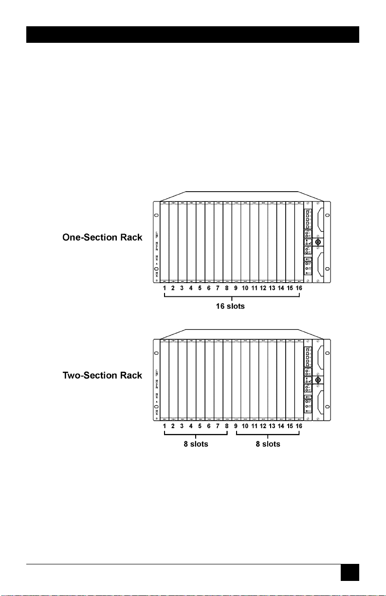
29
CHAPTER 3: Functions
That is, one bus connects to eight slots, and the other bus connects to the
other eight slots (see Figure 3-9).
Switch/patch cards provide AB switch with optional patch capabilities. Normally,
you will place these cards in a one-section rack. Place the cards in any combination
and in any order.
NOTE
Place the spare card in the rightmost slot of a section. Place the online
cards in the other slots.
Figure 3-9. Rack Configurations.
Page 33

30
PRO SWITCHING SYSTEM
4. Components
This chapter describes the Pro Switching System components and component
functions, and provides model numbers.
4.1 Rackmount Chassis
The Rackmount Chassis (SM700A) has 16 slots for front cards, 16 slots for rear
cards, one slot (the rightmost slot) for the control card, and two slots for power
supplies.
The Rackmount Chassis must include a control card and at least one power
supply (115/230 VAC) to operate properly. If you want power redundancy
(backup), the rack must include two power supplies.
Figure 4-1. Rackmount Chassis Front Ports.
4.1.1 C
ONTROLS
• Key Switch: A key switch on the front of the rack enables or disables manual
operation. This prevents accidental switching from the front of the rack.
To enable manual operation, turn the key to the horizontal (unlocked)
position (represented by the icon of the open padlock on the control card).
See Figure 4-2.
To disable manual operation, turn the key to the vertical (locked) position
(represented by the icon of the closed padlock on the control card).
Page 34

31
CHAPTER 4: Components
Figure 4-2. Key Switch Unlocked.
4.1.2 P
ORTS
• COMM[unication] ports: On the rear of the rack, there are two
communication ports: COMM IN (DB25 male) and COMM OUT (DB25
female). For some system setups, use these ports to connect the rack to the
managing PC. However, for SNMP setups, use the 10BASE-T connector on the
control card to connect the rack to the managing PC.
• MON[itoring] ports: On the rear of the rack, there are two monitoring ports:
ANALOG (RJ-45 female) and DIGITAL (DB25 female). Use these ports to
connect monitoring buses together and to connect monitoring and testing
equipment to the buses.
• AUX[iliary] port: On the rear of the rack, there is one auxiliary port: AUX
(DB9 female). Use this port to set SNMP/Telnet configurations for the rack
when you can’t access the rack through the 10BASE-T connector (on the
control card).
• Power connectors: The rear of the rack contains two power connectors:
POWER 1 and POWER 2. Use these connectors to attach power sources to the
corresponding power supplies.
Page 35

32
PRO SWITCHING SYSTEM
Figure 4-3. Rackmount Chassis Rear Ports.
4.2 Control Cards
Table 4-1. Control Cards
Model Description
SM701C SNMP 10BASE-T
SM702C VT100™
The control card coordinates all rack functions, communicates with other racks,
and communicates with the management PC. Each rack must have one control
card, inserted into the rightmost slot.
4.2.1 C
ONTROLS
• GANG: There are five gang switches: N, A, B, C, and D. When the key switch is
in the horizontal position, you can use these switches to change all lines in a
rack. If you press A, B, C, or D, the control card switches all lines in the rack to
that position. If you press N, the control card switches all lines in the rack to
the normal position. Use the NORM SET pushbutton to define the normal
position for all lines.
• NORM SET: This pushbutton sets the N gang switch. When you press this
button, the Pro Switching System stores the current switch settings of each line
Page 36

33
CHAPTER 4: Components
as the normal position. Then, when you press the N gang switch, all lines
switch to the normal position.
• LAMP TEST: This pushbutton lights all LEDs in the rack. You can use it to
determine if an LED is operating correctly.
• RESET: This switch performs a warm reset or a cold reset, depending on its
associated DIP switch setting. A warm reset reboots the CPU without affecting
the operator-programmed data that is stored in CPU RAM (for example, alarm
definitions). A cold reset reboots the CPU and deletes all operatorprogrammed data that is stored in the CPU RAM, reinitializing the system.
4.2.2 LED
S
• OK (green): There is one OK LED for power supply 1 (PS1) and one for
power supply 2 (PS2). When lit, this LED indicates that the relevant power
supply is functioning.
• FAN FAIL (red): There is one FAN FAIL LED for PS1 and one for PS2. When
lit, this LED indicates that the fan in the relevant power supply is not
functioning.
• LINK ON (green): This LED, when lit, indicates that the control card is
functioning and capable of communicating with other racks and with the
central PC. When not lit, this LED indicates that the control card has failed.
When the control card fails, COMM IN is physically shorted to COMM OUT,
bypassing the failed control card.
Page 37

34
PRO SWITCHING SYSTEM
Figure 4-4. Control Card.
Page 38

35
CHAPTER 4: Components
4.3 Front Cards
Table 4-2. Switch/Patch Front Cards
Model Interface Switch Patch Switched # of LEDs Alarms Mon. Bus Compatible
Cond. Slots Rear
Cards
SM705C RS-232/V.24 A/B 4-cavity 23 1 √√√SM720C
SM706C V.35 A/B 4-cavity 19 1 √√ SM721C
SM707C RS-530 A/B 4-cavity 23 1 √√√SM720C
SM708C DB15 SM722C
SM709C RJ-11 A/B — 4 1 SM723C
SM710C RJ-45 A/B — 8 1 SM724C
Front cards work with rear cards to manage lines. The front card contains the
switching and patching circuitry, while the rear card contains the cable interface
circuitry. The front card and the rear card mate when they are inserted into the
rack.
In a rack, there are 16 slots for front cards and 16 corresponding slots for rear
cards. The cards occupy one slot. The front cards are called Switch/Patch Cards.
S
WITCH/PATCHCARDS
Switch/patch cards provide A/B switching with optional patching capabilities.
Switch/patch cards are available for use with RS-232, V.35, RS-530, RJ-11, RJ-45,
and DB15 interfaces. Each switch/patch card occupies one slot.
Controls
A/B switch cards have a toggle switch with two settings: A and B. To change the
switch to the A position, move the toggle switch toward the A setting. To change
the switch to the B position, move the toggle switch toward the B setting.
LEDs
Switch/patch cards have some or all of the following LEDs:
• Switch position (green): Pro Switching System cards, where appropriate,
indicate switch position. For example, A/B switch cards indicate if the line is
currently switched to the A or B position.
Page 39

36
PRO SWITCHING SYSTEM
• Signals (red): Some Pro Switching System cards include LEDs that indicate the
current status of signals. For example, RS-232 cards with LEDs indicate the
status of TD, RD, RTS, CTS, DSR, DCD, DTR, and RI.
• ALM (red): When flashing, indicates that the line passing through this card is
generating an alarm condition.
• MON (green): When lit, indicates that the line is currently connected to the
monitoring bus. The connection is made for monitoring and testing
operations.
• BK (red): When lit, indicates that the line is currently broken. The break is
made for testing operations.
• TS (red): Not used.
• LP (red): Not used.
Patch Cavities
Switch/patch cards can have up to four patch cavities, which allow you to monitor
and test the lines. Normally, data transmission is normal through. That is, the DTE
is connected to the DCE. However, if you connect a patch cord to a patch cavity,
you can monitor or test the line as follows:
• COMP: When you insert a patch cord into the COMP cavity, the circuit is
broken and the cord is connected to the DTE. You can use this connection to
test the DTE.
• MODEM: When you insert a patch cord into the MODEM cavity, the circuit is
broken and the cord is connected to the DCE. You can use this connection to
test the DCE.
• MON A: When you insert a patch cord into the MON A cavity, it is connected
to the circuit between the DTE A port and the DCE port. The circuit is not
broken. You can use this connection to monitor the signals.
• MON B: When you insert a patch cord into the MON B cavity, it is connected
to the circuit between the DTE B port and the DCE port. The circuit is not
broken. You can use this connection to monitor the signals.
Page 40

37
CHAPTER 4: Components
Figure 4-5. Switch/Patch Card.
4.4 Rear Cards
Rear cards work with front cards to manage lines. The front card contains the
switching and patching circuitry; the rear card contains the cable interface
circuitry. The front card and the rear card mate when they are inserted into a rack.
Rear cards and front cards that mate must be compatible. See the description of
the front card (Section 4.3) for a list of the compatible rear cards.
In a rack, there are 16 slots for front cards, and 16 corresponding slots for rear
cards. The cards occupy one slot.
Rear cards have ports that correspond with their applications. They also have a
slot number window that indicates the number of the slot in which the card is
installed.
Page 41

38
PRO SWITCHING SYSTEM
Table 4-3. Rear Cards
Model Application # of Slots Connectors
SM720C A/B switch (and patch) 1 A, B, Common: DB25F
SM721C A/B switch (and patch) 1 A, B, Common: V.35F
SM722C A/B switch (and patch) 1 A, B, Common: DB15F
SM723C A/B switch 1 A, B, Common: RJ-11
SM724C A/B switch 1 A, B, Common: RJ-45
4.5 Power Supplies
Power supplies allow you to supply power to a rack. You can have one or two (for
redundant power) power supplies in a rack. There is one type of power supply: the
SM750A. It’s a 115/230-VAC, 50- to 60-Hz auto-selectable power supply.
Table 4-4. Power Supply
Model Description
SM750A Power supply, 115/230 VAC, 50-60 Hz (auto-selectable)
4.6 Software
To control the Pro Switching System from a PC, you need the Pro Switching
System Software (SM701A). This software works as an application under HP
OpenView Windows.
Table 4-5. Software
Model Description
SM701A Pro Switching System Software
Page 42

39
CHAPTER 4: Components
4.7 System Cables
System cables connect racks to the central PC via COMM ports. The first rack at a
site is connected to the central site; the other racks are daisychained together. For
SNMP applications, you don’t need to connect system cables to the COMM ports.
4.8 Accessories
4.8.1 B
LANK
P
ANELS
Blank panels cover empty slots in the rack.
Table 4-6. Blank Panels
Model Description
SM730 Blank Panel, Unused rear slot
SM740 Blank Panel, Unused front slot
4.8.2 P
ATCHCORDS
Patch cords allow you to connect equipment to patch cavities. Patch cords are
available in a variety of lengths and with a variety of connectors. Call Technical
Support for more information.
Page 43

40
PRO SWITCHING SYSTEM
5. Installation
This chapter shows you how to install a Pro Switching System for SNMP
management.
5.1 Preparing the Rack
“Preparing the rack off-site” sets up the rack so that a technician can quickly install
the rack on-site, leave, and let the network manager perform the necessary
SNMP/Telnet configurations to the rack remotely.
To prepare the rack:
• Fill Out the Rack Description Guide (Section 5.1.1)
• Configure the Control Card (Section 5.1.2)
• Install Components (Section 5.1.3)
• Enter IP address into rack (Section 5.1.4)
5.1.1 F
ILLOUT THERACKDESCRIPTIONGUIDE
1. Make the appropriate number of photocopies of the Rack Description Guide
sheet (shown in Appendix A) for the number of racks to be installed.
2. Complete the information on the sheets for each rack. (See the “Rack
Description Guide Example” on the next page.)
3. Make two photocopies of the completed sheets.
4. Give one set of sheets to the installation technician. Give another set to the
network manager. Store the original sheets in a master file.
Page 44

41
CHAPTER 5: Installation
Rack Description Guide Example
Site name:
Password (DIP switches):
Rack name:
Rack address (DIP switches):
Baud rate:
IP Address:
Application: Switch/patch
Slot: Connection:
1 A: Satellite, B: Telco, C: User001
2 A: Satellite, B: Telco, C: User002
3 A: Satellite, B: Telco, C: User003
4 A: Satellite, B: Telco, C: User004
5 A: Satellite, B: Telco, C: User005
6 A: Satellite, B: Telco, C: User006
7 A: Satellite, B: Telco, C: User007
8 A: Satellite, B: Telco, C: User008
9 A: Satellite, B: Telco, C: User009
10 A: Satellite, B: Telco, C: User010
11
12
13
14
15
16
Page 45

42
PRO SWITCHING SYSTEM
5.1.2 C
ONFIGURE THECONTROLCARD AND
DIP S
WITCHES
Each rack must have one control card, which is inserted into the rightmost slot of
the rack. The control card coordinates all rack functions, communicates with other
racks, and communicates with the management PC.
Before installing the control card, you must configure its battery jumper and
DIP switches.
Figure 5-1. Control Card.
CAUTION
Cards are electrostatic-discharge (ESD) sensitive. To prevent ESD
damage, always wear grounding wrist straps when touching, removing,
or inserting cards. Store and transport cards in sealed, static-shielding
bags.
NOTE
Before installing the control card, the battery must be enabled.
Configuring the Battery Jumper
1. Locate the battery jumper pins, located above the battery and labeled JP1, on
the control card. (The control card normally ships with the battery disabled—
its jumper rests on only one of the pins, disabling the battery during storage
and transportation.)
Page 46

43
CHAPTER 5: Installation
2. To activate the battery, connect the pins for a two-pin group by placing the
jumper across both pins. For a three-pin group, connect jumper cap across
the two pins labeled ON.
NOTE
To disable the battery on the control card, for a two-pin jumper group
disconnect the jumper cap across both pins so they rest on only one
pin. For a three-pin jumper group, connect the jumper cap across two
pins labeled OFF.
Setting the Configuration DIP Switches (DS5)
The configuration DIP switches set the following:
• Enable/disable rack password
• Cold/warm RESET button configuration
• Enable/disable NORM SET and N gang switch buttons
• Communication baud rate
Tables 5-1 through 5-4 illustrate the DIP-switch settings.
DIP Switch Tables
Table 5-1. DIP Switches at DS7
Switch Position In order to… Notes
1 ON Enable the Ethernet port.
OFF Disable the Ethernet port.
2 OFF – Always set to OFF.
3 ON Enable the AUX port.
OFF Disable the AUX port.
Page 47

44
PRO SWITCHING SYSTEM
Table 5-2. DIP Switches at DS6
Switch Position In order to… Notes
1 to 8 OFF – Always set to OFF.
Table 5-3. DIP Switches at DS5
Switch Position In order to… Notes
1 ON Disable the password. All racks at a site must use the
same password.
OFF Enable the password. When you enable the
password, the management
PC uses the password to
communicate with the rack.
When you disable the
password, the management
PC disregards the password.
2 ON Configure the RESET button A cold reset erases all user-
to perform a “cold” reset programmed system parameter
when pressed. data that are stored in
the Pro Switching System RAM
and reboots the CPU,
reinitializing the system.
OFF Configure the RESET button A warm reset reboots the CPU
to perform a “warm” reset without affecting the userwhen pressed. programmed system
system parameter data (such
as alarm definitions) that are
stored in the Pro Switching
System RAM.
Page 48

45
CHAPTER 5: Installation
Table 5-3 (continued). DIP Switches at DS5
Switch Position In order to… Notes
3 ON Disable the NORM SET and When you enable
N gang switch buttons. NORM SET, you can
use the control card
NORM SET switch
and the N gang
switch. When you
disable NORM
OFF Enable the NORM SET and SET, you cannot use
N gang switch buttons. these switches.
4, 5, 6 OFF – Always set to OFF.
7, 8 7 8 All racks at a site
ON ON Set the baud rate to 2400 bps. must use the same
OFF ON Set the baud rate to 4800 bps. baud rate. The baud
ON OFF Set the baud rate to 9600 bps. rate DIP switches set
OFF OFF Set the baud rate to 19200 bps. the baud rate for
communication
between the rack and
the management PC.
Page 49

46
PRO SWITCHING SYSTEM
Table 5-4. DIP-Switch Settings at DS3 and DS4
To set the password (DS3) to…
Set Switches 1 through 8 to… To set the rack address (DS4) to…
12345678
ON ON ON ON ON ON ON ON 000
off ON ON ON ON ON ON ON 001
ON off ON ON ON ON ON ON 002
off off ON ON ON ON ON ON 003
ON ON off ON ON ON ON ON 004
off ON off ON ON ON ON ON 005
ON off off ON ON ON ON ON 006
off off off ON ON ON ON ON 007
ON ON ON off ON ON ON ON 008
off ON ON off ON ON ON ON 009
ON off ON off ON ON ON ON 010
off off ON off ON ON ON ON 011
ON ON off off ON ON ON ON 012
off ON off off ON ON ON ON 013
ON off off off ON ON ON ON 014
off off off off ON ON ON ON 015
ON ON ON ON off ON ON ON 016
off ON ON ON off ON ON ON 017
ON off ON ON off ON ON ON 018
off off ON ON off ON ON ON 019
ON ON off ON off ON ON ON 020
off ON off ON off ON ON ON 021
ON off off ON off ON ON ON 022
off off off ON off ON ON ON 023
ON ON ON off off ON ON ON 024
off ON ON off off ON ON ON 025
ON off ON off off ON ON ON 026
off off ON off off ON ON ON 027
ON ON off off off ON ON ON 028
off ON off off off ON ON ON 029
ON off off off off ON ON ON 030
off off off off off ON ON ON 031
ON ON ON ON ON off ON ON 032
Page 50

47
CHAPTER 5: Installation
Table 5-4. DIP-Switch Settings at DS3 and DS4
To set the password (DS3) to…
Set Switches 1 through 8 to… To set the rack address (DS4) to…
12345678
off ON ON ON ON off ON ON 033
ON off ON ON ON off ON ON 034
off off ON ON ON off ON ON 035
ON ON off ON ON off ON ON 036
off ON off ON ON off ON ON 037
ON off off ON ON off ON ON 038
off off off ON ON off ON ON 039
ON ON ON off ON off ON ON 040
off ON ON off ON off ON ON 041
ON off ON off ON off ON ON 042
off off ON off ON off ON ON 043
ON ON off off ON off ON ON 044
off ON off off ON off ON ON 045
ON off off off ON off ON ON 046
off off off off ON off ON ON 047
ON ON ON ON off off ON ON 048
off ON ON ON off off ON ON 049
ON off ON ON off off ON ON 050
off off ON ON off off ON ON 051
ON ON off ON off off ON ON 052
off ON off ON off off ON ON 053
ON off off ON off off ON ON 054
off off off ON off off ON ON 055
ON ON ON off off off ON ON 056
off ON ON off off off ON ON 057
ON off ON off off off ON ON 058
off off ON off off off ON ON 059
ON ON off off off off ON ON 060
off ON off off off off ON ON 061
ON off off off off off ON ON 062
off off off off off off ON ON 063
ON ON ON ON ON ON off ON 064
off ON ON ON ON ON off ON 065
Page 51

48
PRO SWITCHING SYSTEM
Table 5-4 (continued). DIP-Switch Settings at DS3 and DS4
To set the password (DS3) to…
Set Switches 1 through 8 to… To set the rack address (DS4) to…
12345678
ON off ON ON ON ON off ON 066
off off ON ON ON ON off ON 067
ON ON off ON ON ON off ON 068
off ON off ON ON ON off ON 069
ON off off ON ON ON off ON 070
off off off ON ON ON off ON 071
ON ON ON off ON ON off ON 072
off ON ON off ON ON off ON 073
ON off ON off ON ON off ON 074
off off ON off ON ON off ON 075
ON ON off off ON ON off ON 076
off ON off off ON ON off ON 077
ON off off off ON ON off ON 078
off off off off ON ON off ON 079
ON ON ON ON off ON off ON 080
off ON ON ON off ON off ON 081
ON off ON ON off ON off ON 082
off off ON ON off ON off ON 083
ON ON off ON off ON off ON 084
off ON off ON off ON off ON 085
ON off off ON off ON off ON 086
off off off ON off ON off ON 087
ON ON ON off off ON off ON 088
off ON ON off off ON off ON 089
ON off ON off off ON off ON 090
off off ON off off ON off ON 091
ON ON off off off ON off ON 092
off ON off off off ON off ON 093
ON off off off off ON off ON 094
off off off off off ON off ON 095
Page 52

49
CHAPTER 5: Installation
Table 5-4 (continued). DIP-Switch Settings at DS3 and DS4
To set the password (DS3) to…
Set Switches 1 through 8 to… To set the rack address (DS4) to…
12345678
ON ON ON ON ON off off ON 096
off ON ON ON ON off off ON 097
ON off ON ON ON off off ON 098
off off ON ON ON off off ON 099
ON ON off ON ON off off ON 100
off ON off ON ON off off ON 101
ON off off ON ON off off ON 102
off off off ON ON off off ON 103
ON ON ON off ON off off ON 104
off ON ON off ON off off ON 105
ON off ON off ON off off ON 106
off off ON off ON off off ON 107
ON ON off off ON off off ON 108
off ON off off ON off off ON 109
ON off off off ON off off ON 110
off off off off ON off off ON 111
ON ON ON ON off off off ON 112
off ON ON ON off off off ON 113
ON off ON ON off off off ON 114
off off ON ON off off off ON 115
ON ON off ON off off off ON 116
off ON off ON off off off ON 117
ON off off ON off off off ON 118
off off off ON off off off ON 119
ON ON ON off off off off ON 120
off ON ON off off off off ON 121
ON off ON off off off off ON 122
off off ON off off off off ON 123
ON ON off off off off off ON 124
off ON off off off off off ON 125
ON off off off off off off ON 126
off off off off off off off ON 127
ON ON ON ON ON ON ON off 128
Page 53

Table 5-4 (continued). DIP-Switch Settings at DS3 and DS4
To set the password (DS3) to…
Set Switches 1 through 8 to… To set the rack address (DS4) to…
12345678
off ON ON ON ON ON ON off 129
ON off ON ON ON ON ON off 130
off off ON ON ON ON ON off 131
ON ON off ON ON ON ON off 132
off ON off ON ON ON ON off 133
ON off off ON ON ON ON off 134
off off off ON ON ON ON off 135
ON ON ON off ON ON ON off 136
off ON ON off ON ON ON off 137
ON off ON off ON ON ON off 138
off off ON off ON ON ON off 139
ON ON off off ON ON ON off 140
off ON off off ON ON ON off 141
ON off off off ON ON ON off 142
off off off off ON ON ON off 143
ON ON ON ON off ON ON off 144
off ON ON ON off ON ON off 145
ON off ON ON off ON ON off 146
off off ON ON off ON ON off 147
ON ON off ON off ON ON off 148
off ON off ON off ON ON off 149
ON off off ON off ON ON off 150
off off off ON off ON ON off 151
ON ON ON off off ON ON off 152
off ON ON off off ON ON off 153
ON off ON off off ON ON off 154
off off ON off off ON ON off 155
ON ON off off off ON ON off 156
off ON off off off ON ON off 157
ON off off off off ON ON off 158
off off off off off ON ON off 159
ON ON ON ON ON off ON off 160
off ON ON ON ON off ON off 161
50
PRO SWITCHING SYSTEM
Page 54

51
CHAPTER 5: Installation
Table 5-4 (continued). DIP-Switch Settings at DS3 and DS4
To set the password (DS3) to…
Set Switches 1 through 8 to… To set the rack address (DS4) to…
12345678
ON off ON ON ON off ON off 162
off off ON ON ON off ON off 163
ON ON off ON ON off ON off 164
off ON off ON ON off ON off 165
ON off off ON ON off ON off 166
off off off ON ON off ON off 167
ON ON ON off ON off ON off 168
off ON ON off ON off ON off 169
ON off ON off ON off ON off 170
off off ON off ON off ON off 171
ON ON off off ON off ON off 172
off ON off off ON off ON off 173
ON off off off ON off ON off 174
off off off off ON off ON off 175
ON ON ON ON off off ON off 176
off ON ON ON off off ON off 177
ON off ON ON off off ON off 178
off off ON ON off off ON off 179
ON ON off ON off off ON off 180
off ON off ON off off ON off 181
ON off off ON off off ON off 182
off off off ON off off ON off 183
ON ON ON off off off ON off 184
off ON ON off off off ON off 185
ON off ON off off off ON off 186
off off ON off off off ON off 187
ON ON off off off off ON off 188
off ON off off off off ON off 189
ON off off off off off ON off 190
off off off off off off ON off 191
Page 55

52
PRO SWITCHING SYSTEM
Table 5-4 (continued). DIP-Switch Settings at DS3 and DS4
To set the password (DS3) to…
Set Switches 1 through 8 to… To set the rack address (DS4) to…
12345678
ON ON ON ON ON ON off off 192
off ON ON ON ON ON off off 193
ON off ON ON ON ON off off 194
off off ON ON ON ON off off 195
ON ON off ON ON ON off off 196
off ON off ON ON ON off off 197
ON off off ON ON ON off off 198
off off off ON ON ON off off 199
ON ON ON off ON ON off off 200
off ON ON off ON ON off off 201
ON off ON off ON ON off off 202
off off ON off ON ON off off 203
ON ON off off ON ON off off 204
off ON off off ON ON off off 205
ON off off off ON ON off off 206
off off off off ON ON off off 207
ON ON ON ON off ON off off 208
off ON ON ON off ON off off 209
ON off ON ON off ON off off 210
off off ON ON off ON off off 211
ON ON off ON off ON off off 212
off ON off ON off ON off off 213
ON off off ON off ON off off 214
off off off ON off ON off off 215
ON ON ON off off ON off off 216
off ON ON off off ON off off 217
ON off ON off off ON off off 218
off off ON off off ON off off 219
ON ON off off off ON off off 220
off ON off off off ON off off 221
ON off off off off ON off off 222
off off off off off ON off off 223
ON ON ON ON ON off off off 224
Page 56

53
CHAPTER 5: Installation
Table 5-4 (continued). DIP-Switch Settings at DS3 and DS4
To set the password (DS3) to…
Set Switches 1 through 8 to… To set the rack address (DS4) to…
12345678
off ON ON ON ON off off off 225
ON off ON ON ON off off off 226
off off ON ON ON off off off 227
ON ON off ON ON off off off 228
off ON off ON ON off off off 229
ON off off ON ON off off off 230
off off off ON ON off off off 231
ON ON ON off ON off off off 232
off ON ON off ON off off off 233
ON off ON off ON off off off 234
off off ON off ON off off off 235
ON ON off off ON off off off 236
off ON off off ON off off off 237
ON off off off ON off off off 238
off off off off ON off off off 239
ON ON ON ON off off off off 240
off ON ON ON off off off off 241
ON off ON ON off off off off 242
off off ON ON off off off off 243
ON ON off ON off off off off 244
off ON off ON off off off off 245
ON off off ON off off off off 246
off off off ON off off off off 247
ON ON ON off off off off off 248
off ON ON off off off off off 249
ON off ON off off off off off 250
off off ON off off off off off 251
ON ON off off off off off off 252
off ON off off off off off off 253
ON off off off off off off off 254
off off off off off off off off 255
Page 57

54
PRO SWITCHING SYSTEM
To Set the Configuration DIP Switches
1. Locate the DIP switch sets labeled DS7, DS6, and DS5 on the control card.
2. Use the DIP switch tables to set the DS7, DS6, and DS5 DIP switches. Tables 51 through 5-3 show the switch settings and provide notes that describe the
DIP switch functions.
Setting the Rack Address DIP Switches (DS4)
The rack address DIP switches set the address that the management PC uses to
distinguish each rack.
Rack addresses can have any value between 0 and 255. However, each rate at a
site must have a unique rack address.
1. Locate the DIP switch sets labeled DS4 on the control card.
2. Use Table 5-4 to set the DS4 DIP switches. The table shows the switch settings
for each rack address.
NOTE
When assigning rack addresses, make sure that each rack at a site has
a unique address.
Setting the Password DIP Switches (DS3)
If you enabled the password DIP switch (switch 1 on DS5), you must set the
password DIP switches (DS3) to assign a numeric password to the rack. If you
disabled the password, skip this step.
The password DIP switches set the password that the management PC must use
when communicating with the rack. The password can have any value between 0
and 255. However, each rack at a site must have the same password.
1. Locate the DIP switch sets labeled DS3 on the control card.
2. Use Table 5-4 to set the DS3 DIP switches. The table shows the switch settings
for each password.
Installing the Control Card
1. Insert the control card into the rightmost slot of the rack.
2. Secure the card in the rack by tightening the screws.
Page 58

55
CHAPTER 5: Installation
5.1.3 I
NSTALLINGRACKCOMPONENTS
A rack has 16 slots for front cards, 16 slots for rear cards, one slot for the control
card, and two slots for power supplies.
To operate, a rack must include a control card and at least one power supply. If
you want power redundancy (power backup), the rack must include two power
supplies.
Front and Rear Cards
In each rack, you can install front and rear cards for switching/patching.
To Install Switch/Patch Cards
1. Insert the front cards and tighten the screws. You need not fill all slots in a
rack or fill slots in any particular order.
2. Insert the corresponding rear cards and tighten the screws.
To Install the Power Supplies
Insert the power supplies into the power supply slots located on the front right side
of the rack. If you are only installing one power supply, you can insert it into either
slot.
To Power Up and Test the LEDs
1. Connect the chassis ground stud to ground. The ground stud is located just
below the power cord connectors on the rear of the rack.
2. Connect the power cords. For each power supply, connect one end of a
power cord to the power connector at the rear of the rack. Connect the other
end of the power cord to a power source. The rack automatically powers up as
soon as you connect the power cords.
3. Test the LEDs by pressing the LAMP TEST button on the front of the control
card. All LEDs in the rack should light.
5.1.4 E
NTER
IP A
DDRESS INTORACK
By entering an IP address into the rack, the network manager can access the rack
remotely and configure it for SNMP management after the rack has been installed.
NOTE
You MUST enter an IP address into the rack in order to access it
remotely.
Page 59

56
PRO SWITCHING SYSTEM
To Enter the IP Address into the Rack
1. Connect a VT100 terminal to the AUX port (located at the rear of the unit).
Use a null-modem-type cable or equivalent. Refer to Table 5-5.
Table 5-5. AUX Port Pin Assignments
Pin # Signal
1 Chassis GND
2 TXD
3 RXD
4 RTS
5 CTS
6 NOT USED
7 Signal GND
8 NOT USED
9 NOT USED
2. Set the communication settings of the VT100 terminal. Refer to Table 5-6.
Table 5-6. VT100 Terminal Communication Settings
Bits per second 9600
Data bits 8
Parity None
Stop bits 1
3. Assign an IP address to the Pro Switching System by entering the following
into the terminal:
SET RACK n IP ADDRESS a.b.c.d
where:
n is the rack address (set by the user via DIP-switch-group DS4), and
a.b.c.d is the IP address.
Example:
SET RACK 1 IP ADDRESS
Page 60

57
CHAPTER 5: Installation
192.19.211.10
NOTE
Once you enter the IP address into the rack, it is stored in batterybacked-up memory on the control card and will not be lost when you
disconnect the power cord.
5.2 Installing the Rack
The on-site installation consists of mounting the rack into a cabinet, connecting
the necessary cables, and powering up the rack. The network manager can further
configure the rack from a remote management center via a Telnet session.
At each site, you can install up to 256 racks. For SNMP, the racks may be
connected to a terminal server using the 10BASE-T connector located on the
control card.
5.2.1 M
OUNTING THERACK INTO THECABINET
1. Carefully insert the rack into the cabinet.
2. Secure the rack with screws at the rack sides.
5.2.2 C
ONNECTINGLINECARDCABLES FORSWITCH/PATCHCARDS
Connect the cables to the rear ports, as appropriate for your application.
5.2.3 C
ONNECTING
10BASE-T C
ABLE
To control your rack via SNMP/Telnet sessions, you must connect the rack to your
LAN using the 10BASE-T connector (RJ-45) located on the front of the control
card.
5.2.4 P
OWERUP AND
LED T
EST
1. Connect the chassis ground stud to ground. The ground stud is located just
below the power cord connectors on the rear of the rack.
2. Connect the power cords. For each power supply, connect one end of a
power cord to the power connector at the rear of the rack. Connect the other
end of the power cord into a power source. The rack automatically powers up
as soon as you connect the power cords.
3. Test the LEDs by pressing the LAMP TEST button on the front of the control
card. All LEDs in the rack should light.
Page 61

58
PRO SWITCHING SYSTEM
5.3 Software/Management Installation
To install the software and management PC:
• Install the management PC (Section 5.3.1).
• Install the software (HP OpenView and SNMP application software). See
Section 5.3.2 and 5.3.3.
5.3.1 I
NSTALLING THEMANAGEMENT
PC
You can manage a Pro Switching System from an IBM compatible computer
installed with HP OpenView and the SNMP application software (SM701A).
The Minimum PC Requirements:
Processor: 486DX2
RAM: 16 MB
Display: VGA
Operating System: Windows 95
To Install a Management PC
1. Follow the manufacturer’s installation instructions for setting up your PC.
2. Install a remote access device (modem, Ethernet card, etc.) into your PC that
will allow you to connect to the racks using TCP/IP. Follow the
manufacturer’s installation instructions for installing the device.
5.3.2 I
NSTALL
HP O
PENVIEW
Install the C2.14 Release
1. Insert the HP OpenView installation CD into your CD-ROM drive.
2. From your Windows 95 desktop, click on Start, Run… The Run screen
appears.
3. Enter the following: E:\OV214\Disk1\Setup (if necessary, replace E:\ with the
correct letter of the CD-ROM drive).
Installation begins. Follow all installation instructions that appear on your
screen.
Page 62

59
CHAPTER 5: Installation
Make sure to choose “SNMP over TCP/IP Communications” when the screen
offering this selection appears.
Upgrade to C2.17:
1. When the installation ends, return to your Windows 95 desktop and click on
Start, Run… The Run screen appears.
2. Enter the following: E:\OV217\Setup (if necessary, replace E:\ with the
correct letter of the CD-ROM drive). Upgrading begins. Follow all installation
instructions that appear on your screen.
3. When the installation is complete, restart your computer before running HP
OpenView.
NOTE
After installing the software, you MUST restart your computer before
running HP OpenView.
5.3.3 I
NSTALL
SNMP A
PPLICATIONSOFTWARE
1. Insert Disk 1 into your disk drive.
2. From your Windows 95 desktop, click on Start, Run… The Run screen
appears.
3. Enter the following: A:\Setup. Installation begins. Follow all installation
instructions that appear on your screen.
4. When the installation is complete, restart your computer before running the
application software.
NOTE
After installing the software, you MUST restart your computer before
running the application software.
5.4 System Configuration
Once you enter the IP address into the unit, the network manager can access and
continue configuring the rack remotely through the 10BASE-T connector via
Telnet sessions.
To properly operate your Pro Switching System from your system management
center, you must configure your system with the correct information.
Page 63

60
PRO SWITCHING SYSTEM
This section describes how to configure your system and describes the
SNMP/Telnet ASCII configuration commands. These commands are available via
the serial COMM IN or AUX ports, or via a Telnet session onto the 10BASE-T port
of the unit.
You can obtain the SNMP/Telnet ASCII configuration list of commands via the
HELP SET rack command. Almost all SET commands have a GET counterpart,
which returns the configured value.
Commands are not case-sensitive, although some command parameters such as
community names and passwords might be case-sensitive.
All settings take effect ONLY when you reset the unit.
Use the information you entered in your Rack Description Guide to properly
configure your installed racks.
To Configure your System
1. For each installed rack in your system, establish a Telnet session. The Telnet
session will simulate a terminal screen. Use the IP addresses shown on your
Rack Description Guide sheets to locate the racks.
2. When connected to the rack, press the Enter key. The unit responds with
n:OK, where n represents the assigned unit number. Communication with
the rack is not possible.
3. Using the system configuration commands on the next pages, configure each
rack with the proper settings.
4. To enable the configuration changes, reset the rack using the RESET
command. All settings take effect when the unit is reset.
Pro Switching System 10BASE-T Configuration Commands
Page 64

61
CHAPTER 5: Installation
To Configure Rack Settings
Enter… In order to…
SET RACK n FACTORY DEFAULTS
Clear the battery-backed-up configuration and set all
SNMP/Telnet parameters and MIB variables to their default
values:
DEFAULT ROUTER set to 0.0.0.0
IP ADDRESS set to 0.0.0.0
SNMP MANAGER are all cleared
SNMP READ COMMUNITY NAME set to “public”
SNMP SECURITY TRAPS set to 10
SNMP TRAPS set to ON
SNMP WRITE COMMUNITY NAME set to “private”
SUBNET MASK set to 0.0.0.0
TELNET IDLE TIMEOUT set to 60 minutes
TELNET PASSWORD set to NONE
TELNET SECURITY TRAPS set to 3
SET RACK n DEFAULT ROUTER x.x.x.x
Set the default router to where packets will be sent if their
destination IP address is not on the same network. If the default
router is not set, a proxy ARP server is required for these
packets to reach their destination. Default value: 0.0 0.0
SET RACK n DIGITAL1|ANALOG|DIGITAL2
DISCONNECT|BRIDGE|BREAKDCE|BREAKDTE LINE x
Perform switching operations. This is not a configuration setting.
Entering this command connects the bus of rack n to line x. You
must specify n and x. Enter only one selection from DIGITAL,
ANALOG, or DIGITAL2. Enter only one selection from
DISCONNECT, BRIDGE, BREAKDCE, or BREAKDTE.
Page 65

62
PRO SWITCHING SYSTEM
Enter… In order to…
SET RACK n ECHO ON|OFF
Set echo on or echo off for rack n.
SET RACK n IP ADDRESS x.x.x.x
Define the rack IP address. Default value: 0.0.0.0
SET RACK n LINE x|ALL PORT p
Perform switching operations. This is not a configuration setting.
Entering this command switches one line or all lines to a
specified port.
SET RACK n PING x.x.x.x
Start a ping to the specified destination. An ICMP ECHO request
is sent every second until you press a key. Only one ping can be
active at a time.
SET RACK n SNMP DEFAULTS
Set all MIB variables to their default values.
SET RACK n SNMP MANAGER m IP ADDRESS x.x.x.x
Define an SNMP manager to where traps will be sent. Managers
#1 through #16 are supported. Manager #1 will be defined for
trap transmission to be enabled. Default value: [all values are
cleared]
Page 66

63
CHAPTER 5: Installation
Enter… In order to…
SET RACK n SNMP READ COMMUNITY NAME name
Define the SNMP community name to be accepted for SNMP
GET requests and to be used for traps sent out to managers.
Default value: public
SET RACK n SNMP SECURITY TRAPS x
Define the number of consecutive erroneous community names
received after which an “snmpBadCommunity” trap will be sent.
Default value: 10
SET RACK n SNMP TRAPS ON|OFF
Global setting enabling/disabling traps transmission. Default
value: ON
SET RACK n SNMP WRITE COMMUNITY NAME name
Define the SNMP community name to be accepted for SNMP
SET requests. Default value: private
SET RACK n SUBNET MASK x.x.x.x
Define the rack subnet mask. Default value: 0.0.0.0
SET RACK n TELNET IDLE TIMEOUT x
Define the number of consecutive idle minutes (that is, no
character received) after which a Telnet session will be
disconnected. Default value: 60
Page 67

64
PRO SWITCHING SYSTEM
Enter… In order to…
SET RACK n TELNET PASSWORD password|NONE
Define the login password for incoming Telnet sessions. You will
not be prompted for a password if TELNET PASSWORD is set
to NONE. Default value: NONE
SET RACK n TELNET SECURITY TRAPS x
Define the number of consecutive erroneous login passwords
received after which a “telnetBadPassword” trap will be sent.
Default value: 3
SET RACK n TIME MM/DD/YY DDD HH:MM
Set the time and date for rack n.
To Reset Rack
Enter… In order to…
RESET RACK n
Reset the specified rack n and apply any changed settings.
To Display Rack Settings
Enter… In order to…
GET RACK n CARDS
Display information about the line cards in rack n.
GET RACK n DEFAULT ROUTER
Display the IP address of the default router for rack n.
Page 68

65
CHAPTER 5: Installation
Enter… In order to…
GET RACK n DIPSW
Display the DIP-switch settings for rack n.
GET RACK n DIGITAL1|ANALOG|DIGITAL2
Display information about the bus for rack n. Enter only one of
the three buses: DIGITAL1, ANALOG, or DIGITAL2.
GET RACK n IP ADDRESS
Display the IP address of rack n.
GET RACK n MAC ADDRESS
Display the MAC address of rack n.
GET RACK n SNMP MANAGERS
Display the assigned SNMP managers for rack n.
GET RACK n SNMP READ COMMUNITY NAME
Display the SNMP READ COMMUNITY NAME for rack n.
GET RACK n SNMP SECURITY TRAPS
Display the SNMP security traps for rack n.
GET RACK n SNMP STATUS x
Display the SNMP status x for rack n.
Page 69

66
PRO SWITCHING SYSTEM
Enter… In order to…
GET RACK n SNMP TRAPS
Display the SNMP traps for rack n.
GET RACK n SNMP WRITE COMMUNITY NAME
Display the SNMP WRITE COMMUNITY NAME for rack n.
GET RACK n SUBNET MASK
Display the subnet mask for rack n.
GET RACK n TELNET IDLE TIMEOUT
Display the Telnet idle timeout setting for rack n.
GET RACK n TELNET SECURITY TRAPS
Display the Telnet security traps for rack n.
GET RACK n TELNET STATUS x
Display the Telnet status x for rack n.
GET RACK n TIME
Display the time of rack n.
GET RACK n VERSION
Display the firmware version of rack n.
Page 70

67
CHAPTER 5: Installation
To Display Help
Enter… In order to…
HELP
List the available configuration commands.
HELP SET
List the available SET commands.
HELP GET
List the available GET commands.
HELP RESET
List the available RESET commands.
A Typical SNMP/Telnet Setup Sequence Would Look Like This:
Basic IP settings:
SET RACK 1 FACTORY DEFAULTS
1:OK
SET RACK 1 IP ADDRESS 231.98.4.204
1:OK
SET RACK 1 SUBNET MASK 255.255.255.0
1:OK
SET RACK 1 DEFAULT ROUTER 231.98.4.53
Specific SNMP settings:
SET RACK 1 SNMP WRITE COMMUNITY NAME NETMAN
1:OK
Page 71

68
PRO SWITCHING SYSTEM
SET RACK 1 SNMP MANAGER 1 IP ADDRESS 231.98.4.29
1:OK
SET RACK 1 SNMP MANAGER 2 IP ADDRESS 231.98.4.47
1:OK
Unit reset in order for settings to take effect:
RESET RACK 1
1:VERSION
Black Box Pro Switching System
05.12A
1:SNMP UP!
Connectivity test:
SET RACK 1 PING 231.98.4.49
PING STARTED. PRESS ANY KEY TO STOP.
11:07:44 REPLY FROM 231.98.4.49
11:07:45 REPLY FROM 231.98.4.49
11:07:46 REPLY FROM 231.98.4.49
11:07:47 REPLY FROM 231.98.4.49
11:07:48 REPLY FROM 231.98.4.49
11:07:49 REPLY FROM 231.98.4.49
1:OK
HEALTH CHECK
GET RACK 1 SNMP STATUS 2
1:SNMP STATUS #2
Page 72

69
CHAPTER 5: Installation
IP ADDRESS: 231.098.004.204 SUBNET MASK:
255.255.255.000
DEFAULT ROUTER: 231.098.004.053 MAC ADDRESS:
0X00401601011E
TRAPS: ON
SECURITY TRAPS: 10
READ COMMUNITY: PUBLIC
WRITE COMMUNITY: NETMAN
ETHERNET STATISTICS
NIC INTERRUPTS: 0000008769
DMA FAILURES: 0000000000
MEMORY SHORTAGES: 00000000000
MAX. QUEUE DEPTH: 0000000020
AVAILABLE HEAP: 0000004963
OCTETS TRANSMITTED: 0000133659
OCTETS RECEIVED: 0001100528
FRAME ALIGNMENT ERRORS: 0000000000
CRC ERRORS: 0000000000
FRAMES LOST: 00000000000
COLLISIONS: 00000000000
Page 73

70
PRO SWITCHING SYSTEM
6. Operation
This chapter shows you how to operate the Pro Switching System using the SNMP
application via HP OpenView. It explains the monitor displays through which you
communicate with the system, and guides you step-by-step through the various
aspects of network access and control.
6.1 Overview
6.1.1 SNMP A
PPLICATIONSOFTWARE
You can operate the Pro Switching System using the SNMP application software
that runs under HP OpenView for Windows. The SNMP application uses the
OpenView graphical interface, which allows you to manage networks of devices
from different vendors, using application software that the vendors provide. The
SNMP application software is ordered separately (part number SM701A).
6.1.2 HP O
PENVIEWUSER’SGUIDE
You may already be familiar with HP OpenView. If not, read the HP OpenView
User’s Guide.
6.1.3 N
ETWORKMAP ANDDATABASE
When setting up and controlling your network of Pro Switching System devices,
you will need to create a network map and enter information into a network
database. These operations are interrelated: you enter database information at the
same time as you create the map. This chapter guides you through this procedure.
6.1.4 MAPC
ONCEPTS ANDSTRUCTURE
OpenView Map basics are described in detail in the HP OpenView User’s Guide.
You will work with a map composed of two or more submaps.
NOTE
Map and Submap—In HP OpenView applications, a “map” is not itself a
single screen display or “page.” It is the name given to a group of pages
or “submaps.” Each submap is a separate screen display.
The map represents the network in the form of icons. The icons represent
network components and the sites where they are located. Icons are color-coded to
indicate status. Clicking on an icon allows you to access more detailed network
information.
Page 74

71
CHAPTER 6: Operation
The Pro Switching System map has five levels — overview submap, site submap,
rack status display, line status display, alarm definition display — proceeding in
logical fashion from most general to most particular.
6.1.5 MAPL
EVELS
• Top level: An “overview” submap that shows site icons.
NOTE
Each site in the network is represented on the “overview” submap by a
site icon. No site icon appears on any other submap.
To construct the overview submap, add site icons and enter descriptive
information about each site. Each site icon displays a label box for ready
identification. You may separately add other informative labels outside the icon, if
desired.
• Second level: Clicking on a site icon brings you down to a site submap, which
shows icons representing the rack at that site.
NOTE
Rack icons appear only on a site submap. They are not intermixed with
site icons on the “overview” submap.
To construct the site submap, add rack icons and enter descriptive information
about each rack. Each rack icon displays a label box for ready identification. You
may separately add other informative labels outside the icons, if desired.
• Third level: Clicking on a rack icon brings you into “eye contact” with the front
and rear of the rack (the rack status display). You see detailed front and rear
views, showing line cards, LEDs, and rear connectors.
• Fourth Level: Clicking on a line-card panel opens up a breakout box showing
the status of each lead on the line (the line status display).
• Fifth level: Clicking on a command button on the line status display brings you
down to an alarm definition screen. Here you can define lead status alarms for
the line.
6.2 Initializing PC Control
6.2.1 B
ASICINFORMATIONYOUWILLNEED
Before you can set up the database and the map, you need to obtain and list some
basic system information. Most of what you need is supplied by the Rack
Page 75

72
PRO SWITCHING SYSTEM
Description Guide, which the hardware installation technician(s) have turned in.
Master forms for these guides are provided in Appendix A. You must also have
available the following for each:
• Name for the network (collection of all sites controlled from the PC).
• Sites to include in the network.
• Racks to include on each site.
NOTE
Default USER ID and PASSWORD: The system is shipped with the
default user ID as blackbox and default password as blackbox, both of
which are case sensitive. You must use these to gain entry to the
OpenView program. You must also use them to open a map, until new
Ids and passwords have been defined for one or more users. You can
then delete the default ID and password from the map database.
CAUTION
Once you’ve deleted the default ID and password from a map database,
the only entry to the map is via the newly defined supervisor ID(s) and
password(s). If no one can remember a valid password and ID, the map
is permanently locked and inaccessible.
NOTE
Under the Menu Bar item options, you can customize HP OpenView. In
particular, you can define a map as a default map. When you do this, the
OpenView program opens directly to the default map rather than the
vestibule. However, note the caution on the previous page about
deleting the password. If no one can remember a valid password and ID
for the default map, then not only the map, but OpenView itself is locked
an inaccessible. (To remedy this, edit the OVWIN.INI file. Delete the
name of the default map that appears after the equals sign in the line:
MAP=.)
6.2.2 P
RELIMINARYNOTES ANDCAUTIONS
Deleting a Submap
Do not attempt to delete a Submap by using the OpenView path Edit: Submap:
Delete Submap. Instead, click on the submap icon, then use Edit: Delete.
Renaming a Site
Rename a site only if you have not yet added any components on that site.
Choose site names carefully so you won’t need to change them later.
Page 76

73
CHAPTER 6: Operation
If you must use a new name for a site, delete the old site from the map and
create a new site with the desired name.
Frequent Saves
Avoid losing data by saving your map frequently while creating it.
OpenView works by keeping a permanent file and a working file. At start-up, it
reads from the permanent file and creates a new working file. Whatever data you
enter is resident in the working file until you save it to the permanent file, using
the Save function in the File menu.
Be aware that if you system crashes, any changes you have made since the last
Save operation will be lost. So save early and often!
NOTE
An asterisk after the map title indicates that changes have been made in
the working file since the last time the map was saved.
Backup Copies
You can make a backup copy of a map on a diskette by using the Save As command
and selecting the floppy drive (A:, B:, etc.). A 1.4-MB diskette will hold a good-sized
map.
You can also make a backup copy on the hard drive by using the Save As
command and giving the backup copy a separate name.
Delete Unneeded Map Files
If you save maps that you subsequently abandon, the unused files remain in the
C:\OV directory. To save disk space, you may want to delete the unneeded map
files. To do so, use the DOS Del command, and delete all files beginning with the
map name. (The map name is provided by a file ending in .OVM.)
CAUTION
Do not delete unneeded map files (using the DOS Del command) while
running OpenView.
Delete Unneeded Temp Files
Periodically delete all OpenView Temp files in the Temp directory. This directory
is defined by the Temp directive in the AUTOEXEC.BAT file (for example, SET
TEMP=C:\TEMP).
Page 77

74
PRO SWITCHING SYSTEM
CAUTION
Do not delete unneeded temp files while running OpenView!
Alarm and System Event ASCII Files
The system saves the alarm log in Paradox database files OVALINS.* in the OV
directory. To save disk space between OpenView sessions, erase old alarm log files
that will not be used.
6.3 Creating a System Map
The first step in managing your Pro Switching System is to create a system map.
You can set up the system via screens and prompts. The basic concepts are
described in detail in the HP OpenView User’s Guide.
A systematic and convenient way to set up a database and map is to begin with
basic System menu items. Then proceed to the Definition screens for this System
data.
Notepads (notepad fields labeled Notes), accommodating up to 800 characters,
are provided for sites, racks, lines, communication ports, and all definitions and
operations. You can use these to record information about the network while you
are creating the database and map.
To Create a System Map
1. Log on. From the main menu, choose System, Operator Sign-On, which lets
you log onto the Pro Switching System. Enter the correct user ID and
password.
2. Open a new map. From the main menu, choose File, New. A new map
appears.
3. Name map. From the main menu, choose File, Save As....
4. Add Site Icons. From the main menu, choose Edit, Add.... The Add toolbox
appears. Select Compound Object and Black Box from the dropdown lists to
highlight the Black Box site icon. Click-and-drag the icon onto the new empty
map. A Site Description page appears.
5. Describe Sites. On the Site Description page, enter the site name and other
appropriate information. Click on Add to Network when finished. Repeat
steps 4 and 5 to add more site icons.
Page 78

75
CHAPTER 6: Operation
6. Open level 2 Submap. From your site level (top level) map, double-click on
the Pro Switching System site icon. This opens a submap that lets you add
components to your site.
7. Add Rack Icons. From the Add toolbox, select Component and Pro Switching
System from the dropdown lists to highlight the Pro Switching System unit
icon. Click and drag the icon onto the submap. A Rack Description page
appears.
8. Describe Racks. On the Rack Description page, enter the rack name, IP
address, and other appropriate information. Click on Add to Network when
finished. Repeat Steps 6 and 7 to add more rack icons to your submap.
6.4 HP OpenView Operation
The HP OpenView Operations section describes the the main menu selections—
File, Edit, View, Monitor, Control, Options, Windows, and Help—that are common
to most HP OpenView applications.
Two of the main menu selections—Pro Switching System and System—are not
described here since they are exclusive to the Pro Switching System. They are
described in a separate section.
NOTE
For more help on HP OpenView operations not described in this manual,
refer to the HP OpenView user’s manual, or refer to the HP OpenView
program and select Help, HP OpenView Index... from the main menu.
Page 79

76
PRO SWITCHING SYSTEM
Figure 6-1. HP OpenView Screen.
6.4.1 S
TARTING
HP O
PENVIEW
1. From your Windows 95 desktop, select Start, Programs, HPOpenView, and
choose the HP OpenView icon. HP OpenView starts up and automatically
runs the SNMP application.
2. If a login screen appears, enter the correct user ID and password.
If this is your first session or you have not changed the default user ID and
password settings, enter the following exactly as shown:
User ID: blackbox
Password: blackbox
3. Click on OK to continue. The HP OpenView main screen appears, displaying
a new map named UNTITLED.
Page 80

77
CHAPTER 6: Operation
Figure 6-2. Login Screen.
6.4.2 M
AINMENU
HP OpenView provides a main menu bar that runs across the top of the screen
(Figure 6-3). Almost all the main menu items—File, Edit, View, Monitor, Control,
Options, Windows, and Help—are common to most HP OpenView applications. If
you are already experienced with HP OpenView, these menu items should be very
familiar to you.
However, the Pro Switching System menu and System menu are exclusive to the
Pro Switching System. They are provided by the Pro Switching System application
and are described in Section 6.5.5.
Pro Switching System - Login
blackbox
Page 81

78
PRO SWITCHING SYSTEM
File Edit View Monitor Control Pro Switching System System Options Window Help
Figure 6-3. Main Menu.
6.4.3 F
ILEMENU
The File menu contains the following selections:
•New
• Open
• Save
• Save As
• Check Map
• Print Submap
• Print Object List
• Print Setup
• Load Selection List
• Save Selection List As
• Exit
HP OpenView
Page 82

79
CHAPTER 6: Operation
Figure 6-4. File Menu.
Opening a New Map File
Follow this procedure to create a new empty map onto which you may place icons
to visually organize your system.
1. From the main menu, select File, then New. The Login screen appears (see
Figure 6-5).
2. Enter the User ID (default: blackbox).
3. Enter the Password (default: blackbox).
4. Click on OK to open the new map file.
Page 83

80
PRO SWITCHING SYSTEM
Figure 6-5. Login Screen.
Opening an Existing Map File
Follow this procedure to open a previously saved map file.
1. From the main menu, select File, Open. The Open screen appears (see
Figure 6-6).
Figure 6-6. Open Screen.
Pro Switching System - Login
blackbox
Page 84

81
CHAPTER 6: Operation
2. Locate and select the appropriate file.
3. Click on OK to open the file.
New Submap
You can’t use this menu option with the Pro Switching System. To edit a selected
object, select Edit, then Describe or Monitor, then Describe from the main menu.
Rename Submap
You can’t use this menu option with the Pro Switching System. To edit a selected
object, select Edit, then Describe or Monitor, then Describe from the main menu.
Clear Submap
You can’t use this menu option with the Pro Switching System. To edit a selected
object, select Edit then Describe or Monitor, then Describe from the main menu.
Delete Submap
You can’t use this menu option with the Pro Switching System. To edit a selected
object, select Edit, Describe... or Monitor, Describe... from the main menu.
6.4.4 E
DITMENU
The Edit menu has the following selections:
• Add
• Cut
• Copy
• Paste
• Delete
• Describe
• New Submap
• Rename Submap
• Clear Submap
• Delete Submap
Page 85

82
PRO SWITCHING SYSTEM
• Set Background Image
• Clear Background Image
• Set Home Submap
Display “Add” Toolbox
To display the Add Toolbox from where you can add icons, drawing objects, and
text to your map, select Edit from the main menu, then Add. The Add Toolbox
appears.
Cut/Copy/Paste/Delete
Follow these procedures to edit objects and text.
1. Select the object or text which you are editing.
2. From the main menu, select Edit, then Cut, Copy, Paste, or Delete. The
selected editing is performed.
Describe
Follow this procedure to display the description screen for the selected object. On
the description screen, you can edit or add information about the selected object.
You can also “describe” an object by selecting Monitor, then Describe from the
main menu.
1. Click on the object to select it.
2. From the main menu, select Edit, then Describe. The Description screen for
that object appears.
3. Edit or add the appropriate information about the object.
New Submap
This menu option cannot be used in conjunction with the Pro Switching System.
To edit a selected object, select Edit, then Describe, or Monitor, then Describe
from the main menu.
Rename Submap
This menu option cannot be used in conjunction with the Pro Switching
System. To edit a selected object, select Edit, then Describe or Monitor, then
Describe from the main menu.
Page 86

83
CHAPTER 6: Operation
Clear Submap
This menu option cannot be used in conjunction with the Pro Switching System.
To edit a selected object, select Edit, then Describe or Monitor, then Describe
from the main menu.
Delete Submap
This menu option cannot be used in conjunction with the Pro Switching System.
To edit a selected object, select Edit, then Describe or Monitor, then Describe
from the main menu.
Set Background Image
Follow this procedure to load a background image file for the current submap,
allowing you to more visually represent your system.
For example, you may load the geographic view diagram of a country as a
background image. Then, you may position your icons (representing devices) at
particular points on the image to visually indicate their true geographic locations.
To Set the Background Image
1. Click on the submap to where you are placing the background image.
2. From the main menu, select Edit, then Set Background Image. The Set
Background Image screen appears.
3. Locate and select the desired background image.
4. Click on OK to load the image onto the submap. The image appears on your
submap background.
NOTE
If you cannot see the background image or your icons, trying panning
your submap using the scroll bars or by selecting View, then Pan from
the main menu.
Clear Background Image
Follow this procedure to delete the background image from the submap.
1. Click on the submap where the image is located.
2. From the main menu, select Edit, then Clear Background Image. The image
disappears.
Page 87

84
PRO SWITCHING SYSTEM
Set Home Submap
Follow this procedure to define the top level “Home” submap for the current map.
The home submap is the one displayed when you first display a map, and it should
contain a submap symbol for each submap in the map.
1. From the main menu, select Edit, then Set Home Submap. The Set Home
Submap screen appears.
2. Select the desired submap as the home submap.
3. Click on OK to set.
6.4.5 V
IEW
M
ENU
The View menu has the following selections:
• Zoom 1
• Zoom 1/2
• Zoom 1/4
• Zoom 1/8
• Pan
• Set Grid
• Show Grid
Zoom
Perform this procedure to view the map at normal,
1
⁄2, 1⁄4, or 1⁄8 scale.
1. Click on the submap to select it.
2. From the main menu, select View, then Zoom (choose 1, 1⁄2, 1⁄4, or 1⁄8 scale).
The submap displays at the desired scale.
Pan
Perform this procedure to move the submap view.
1. Click on the submap to select it.
2. From the main menu, select View, then Pan. The pan screen appears,
showing your whole submap. Your icons appear as dots.
Page 88

85
CHAPTER 6: Operation
3. Position the box and click OK to view.
Set Grid
Perform this procedure to set the grid spacing, which is used as a drawing guide.
1. Click on the submap to select it.
2. From the main menu, select View, then Set Grid. The Set Grid screen
appears.
3. Set the horizontal and vertical grid spacing.
4. Click on OK to set.
Show/Hide Grid
Perform this procedure to show or hide the grid on the current submap. The grid
is used as a drawing guide.
1. Click on the submap to select it.
2. From the main menu, select View, then Show/Hide Grid. The grid screen
appears/disappears on the current submap.
6.4.6 M
ONITORMENU
The Monitor menu has the following selections:
• Describe...
• Status Legend...
• Alarm Log...
Describe
Perform this procedure to display the description screen for the selected object.
On the description screen, you can edit or add information about the selected
object.
You can also “describe” an object by selecting Edit, then Describe from the main
menu.
To “Describe” an Object
1. Click on the object to select it.
Page 89

86
PRO SWITCHING SYSTEM
2. From the main menu, select Monitor, then Describe. The description screen
for the object appears.
3. Edit or add the appropriate information for the object.
Status Legend
Follow this procedure to display the status legend, which shows the states of the
objects using color codes. By default, they are:
• Red (Critical): indicates the device is having serious problems, such as being
down.
• Dark Red (Major): indicates a problem with some degradation of operation.
• Orange (Minor): indicates a noncritical condition. There maybe some device
degradation.
• Yellow (Warning): indicates a noncritical condition. No degradation has
occurred.
• Mustard (Marginal): indicates that a device is approaching shutdown or
malfunction.
• Magenta (Informational): indicates that an informational message about the
device has been sent by an application.
• Cyan (Disabled): indicates the device is shut down.
• Wheat (Unmanaged): indicates that the device is not managed by an HP
OpenView application.
• Green (Normal): indicates the device is in a normal state. The device is up and
should be working properly.
• Blue (Unknown): indicates the device application does not report its status, or
the map changed and the status has not been reported to HP OpenView for
Windows.
To Display the Status Legend
From the main menu, select Monitor, then Status Legend. The status legend
screen appears.
Page 90

87
CHAPTER 6: Operation
Alarm Log
Perform this procedure to display the alarm log screen, which displays a list of
alarms and other alarm information:
• Acknowledge: Click on this to acknowledge a particular alarm (highlighted).
The alarm disappears and is stored in the history file.
• Acknowledge All: Click on this to acknowledge all alarms. The alarms
disappear and are stored in the history file.
• Close: Click on this to close the alarm log screen.
• Delete: In the history file, click on this to delete a particular alarm.
• Delete All: In the history file, click on this to delete all alarms.
• Filters: Click on this to customize the types of alarms displayed.
• Go To: Click on (highlight) a specific alarm notice and click on Go To show
the specific device in the alarm condition.
• Help: Click on this to display on-line help.
• History: Click on this to display the alarm history file.
• More Info: Click on this to obtain information (if applicable) on a particular
alarm.
• Print: Click on this to print the alarm log.
To Display the Alarm Log
From the main menu, select Monitor, then Alarm Log. The alarm log screen
appears, showing various display and editing options for the alarms.
To obtain more information on the alarm log screen, click on the Help button.
6.4.7 C
ONTROLMENU
The Control menu has the following selections:
• Browse Web Home Page
• Browse Web Management Page
Page 91

88
PRO SWITCHING SYSTEM
Browse Web Home Page
Follow this procedure to view the device’s home page if the device supports Webbased management. This menu item is only enabled when the selected object
contains a Home Page URL in its Describe information.
1. Click on the device icon to select it.
2. From the main menu, select Control, then Browse Web Home Page.
Browse Web Management Page
Perform this procedure to view the device’s management page if the device
supports Web-based management. This menu item is only enabled when the
selected object contains a Management URL in its Describe information.
1. Click on the device icon to select it.
2. From the main menu, select Control, then Browse Web Management Page.
6.4.8 O
PTIONSMENU
The Options menu has the following selections:
• Protect Map
• Log In
• Log Out
• Set Password
• Customize HP OpenView
• Customize Alarms
• Customize Device Access
Protect Map
Follow this procedure to disable editing of a map via password. It is not meant as a
data security feature but prevents your map from being modified accidentally
during regular operations. Only the editing functions are disabled; setting and
acknowledging alarms are not affected.
Page 92

89
CHAPTER 6: Operation
To Protect Your Map
1. From the main menu, select Options, then Protect Map. The protect map
screen appears.
2. Enter a password.
3. Click OK to enable. The word “Protected” is displayed in the status bar at the
bottom of the OpenView window.
To Unprotect Your Map
1. From the main menu, select Options, then Unprotect Map. The unprotect
map screen appears.
2. Enter the correct password.
3. Click OK to unprotect map and resume editing.
NOTE
The protect password is stored in the OVWIN.INI file under the
[OpenView] section using the Key= string value. If you forget your
password, simply delete the coded password entry in the OVWIN.INI file.
Log In
Follow this procedure to log into OpenView at a new security level. The security
level dialog box appears at the start of OpenView if a password has been assigned.
There are three levels of security: Supervisor, Operator, and Observer. The
Supervisor has full privileges to OpenView features; the Operator has limited
privileges; and the Observer has minimal privileges.
The right-hand side of the description bar shows the current login status of the
user.
To Log In
1. From the main menu, select Options, then Log In. The Log In screen
appears.
2. Select the security level—Supervisor, Operator, or Observer.
3. Enter a password.
4. Click OK to set.
Page 93

90
PRO SWITCHING SYSTEM
NOTE
To set new passwords, select Options, then Set Password from the main
menu.
Log Out
Perform this procedure to disable HP OpenView menus and lock the map. The
only basic OpenView functions available will be the Log In menu item and the
Help menu.
To Log Out
From the main menu, select Options, then Log Out. HP OpenView menus are
disabled and the map is locked.
To enable the menus and unlock the map, select Options, then Log In from the
main menu.
Set Password
Follow this procedure to set passwords for the various security levels—Supervisor,
Operator, and Observer.
To Set Passwords
1. From the main menu, select Options, then Set Passwords. The Set Password
screen appears.
2. Select a security level.
3. Enter a password.
4. Click OK to set.
NOTE
Only the Supervisor has “Set Password” privileges. Users logged in as
Operator or Observer cannot set passwords.
Customize HP OpenView
Perform this procedure to customize HP OpenView Settings.
To Customize HP OpenView
1. From the main menu, select Options, then Customize HP OpenView. The
Customize HP OpenView screen appears.
Page 94

91
CHAPTER 6: Operation
2. Choose the appropriate customize settings.
3. Click OK to set. The full settings will take effect on your next session.
Customize Alarms
Perform this procedure to customize your alarm settings.
1. From the main menu, select Options, then Customize Alarms. The Customize
Alarm screen appears.
2. Choose the appropriate customize settings.
3. Click OK to set.
Customize Device Access
Follow this procedure to customize device access characteristics.
To Customize Device Access
1. From the main menu, select Options, then Customize Device Access. The
Customize Device Access screen appears.
2. Choose the appropriate customize settings.
3. Click OK to set.
6.4.9 W
INDOWMENU
The Window menu displays the following selections:
• Home Submap
• Previous Submap
• Locate Submap
• Locate Object.
Home Submap
Follow this procedure to display your home submap.
To Display Your Home Submap
From the main menu, select Window, then Home Submap. The Home Submap
appears.
Page 95

92
PRO SWITCHING SYSTEM
NOTE
To define your home submap, select Edit, then Set Home Submap from
the main menu.
Previous Submap
Follow this procedure to display the previous submap you were viewing.
From the main menu, select Window, Previous Submap. The previous submap
appears.
Locate Submap
Follow this procedure to locate and display a submap for editing.
1. From the main menu, select Window, then Locate Submap. The Locate
Submap screen appears.
2. Choose the target submap.
3. Click OK to locate. The submap is displayed.
Locate Object
Follow this procedure to display the submap containing the device icon, which you
are locating.
1. From the main menu, select Window, then Locate Object. The Locate Object
screen appears.
2. Choose the target device.
3. Click OK to locate. The submap with the device icon is displayed.
6.4.10 H
ELPMENU
The Help menu displays the following selections:
• HP OpenView Index
• About
HP OpenView Index
Follow this procedure to obtain help information on HP OpenView.
Page 96

93
CHAPTER 6: Operation
1. From the main menu, select Help, then HP OpenView Index. The HP
OpenView Index appear.
2. Use the menus and keywords to search for the desired information.
About
Follow this procedure to view the version number, release date, and copyright
information for HP OpenView for Windows and application software.
From the main menu, select Help, then HP About. The About screen appears.
6.5 Switch Operation
The Operations section describes two HP OpenView main menu selections—Pro
Switching System and System—that are unique to the Pro Switching System.
This section also describes how to operate your Pro Switching System using the
SNMP software application via HP OpenView.
6.5.1 S
ITEDESCRIPTIONSCREEN
The Site Description screen (Figure 6-7) allows you to view and edit information
about your site. All fields in the screen, except Name, can be modified.
To Display the Site Description Screen
1. Right-click on the site icon and select Describe. The Site Description screen
appears.
or
1. Click on the site icon to select it.
2. From the main menu, select Edit, then Describe. The Site Description screen
appears.
or
1. Click on the site icon to select it.
2. From the main menu, select Monitor, then Describe. The Site Description
screen appears.
Page 97

94
PRO SWITCHING SYSTEM
NOTE
You cannot change the Name field in the Site Description screen once
you enter it. If you need to rename your site, you must delete your site
icon and create a new site with the desired name.
Figure 6-7. Site Description Screen.
6.5.2 R
ACKDESCRIPTIONSCREEN
The Rack Description screen (Figure 6-8) allows you to view and edit information
about your rack. You can modify all fields in the screen except Site.
To Display the Rack Description Screen
1. Right-click on the rack icon and select Describe. The Rack Description screen
appears.
or
1. Click on the rack icon to select it.
2. From the main menu, select Edit, then Describe. The Rack Description
screen appears.
or
Pro Switching System - Site Description
Page 98

95
CHAPTER 6: Operation
1. Click on the rack icon to select it.
2. From the main menu, select Monitor, then Describe. The Rack Description
screen appears.
Figure 6-8. Rack Description Screen.
6.5.3 L
INEDESCRIPTIONSCREEN
The Line Description screen allows you to view and edit information about your
line card. You can modify all fields in the screen except Site, Rack, and IP Address.
To Display the Line Description Screen
1. Right-click the rack icon and select Describe. The Rack Description screen
(Figure 6-8) appears.
2. From the Rack Description screen, click on one of the line buttons (1
through 16) in the lower portion of the screen. The Line Description screen
(Figure 6-9) for that line card appears.
Pro Switching System - Rack Description
Page 99

96
PRO SWITCHING SYSTEM
Figure 6-9. Line Description Screen.
6.5.4 S
WITCHMENU
Figure 6-10. Switch Menu.
Pro Switching System - Line Description
Pro Switching System
Page 100

97
CHAPTER 6: Operation
The Switch menu displays the following selections:
• Definitions
Groups
Default Switch
Switch Schedules
Standard Alarms
Alarm Triggered Switching
Monitor Bus
• Operations
Switching
Default Switching
Scheduled Switching
Standard Alarms
Alarm Triggered Switching
• Go To
Site
Rack
Line
• Network
Broadcast
Health Checks
System (All Sites)
Report
Definitions
Figure 6-11. Definitions Menu.
Pro Switching System
 Loading...