

Page 1

1
Compact rack system
occupies just 2U of
vertical space.
Order the SNMP/HTTP
Card for flexible rack
management.
Load-sharing, dualredundant power
supplies.
Daisychain up to 8
racks for additional
connections.
A wide variety of cards
available for different
interfaces.
Cards for mDSL, hDSL,
and iDSL connections.
Up to 50-km distances
between two singlemode fiber cards.
W
hen space is tight, choose the
BLACK BOX
®
16-Port Managed
MicroRACK system. Resilient dualpower supplies and the ability to
mix different types of access
solution cards add up to a compact,
reliable solution—all in only 2U
(3.5") of vertical space in a 19" rack!
Two sturdy front handles allow
the rack to be installed, extracted,
or transported easily. Plus, it’s
expandable; you can cascade
multiple racks and establish up to
320 card connections.
The 16-Port Managed
MicroRACK can not only save you
space and effort, but it also has
slots for a pair of power supplies
that provide redundant power to
keep your mission-critical
applications alive. Each power
supply is capable of providing 100%
of your rack power requirements.
In the event of a power failure, the
other supply immediately takes
over and the MicroRACK alerts you
to the failure. The rack also notifies
the central site operator of the
power failure through the network
management system.
Install up to 16 interface cards in only 2U of rack
space—and manage them via SNMP/HTTP!
Key Features
16-PORT MANAGED MICRORACK
There are two types of rack
power supplies. The AC version
(PS466A) plugs into any standard
AC outlet (90–264 VAC, 50/60 Hz);
the rack comes with one of these
already installed. The DC supply
(PS466A-DC) can be attached to a
site’s -48-VDC power (actual
voltage range can be from -42 to
-60 VDC). Each of these power
supplies—as do all of the function
cards designed for the
MicroRACK—consists of a frontmounted “front card” and a rearmounted “rear card”; these cards
meet at a midplane interface inside
the rack.
A Managed MicroRACK can
take any combination of the power
supplies. A single supply provides
power to up to 16 rack cards. With
a pair of power supplies, you can
provide redundant power for up to
14 rack cards. This way, you can
keep your system operating
smoothly; it won’t come to a
standstill if one supply fails.
Once powered, the rack begins
operating automatically—it has no
on/off switch—and you can check
the status of the power supply via
front-card LEDs.
There are five possible
configurations for the rack:
• Standard—16 cards and
1 power supply;
• Managed—15 cards,
1 SNMP/HTTP Card, and
1 power supply;
• Redundant—14 cards and
2 power supplies;
• Managed/redundant—13
cards, 1 SNMP/HTTP Card,
and 2 power supplies;
• Daisychained/redundant (up to
8 racks)— 13 cards, 1 SNMP/
HTTP Card, or 1 Control
Module, and 2 power supplies.
A wide variety of function
cards are available. You may also
want an SNMP/HTTP network
management module, which
enables you to configure and
perform diagnostics using SNMP
or HTTP over a 10BASE-T Ethernet
connection. If you want to
daisychain racks together, order
the Control Module (RM262C).
Black Box Corporation • 1000 Park Drive • Lawrence, PA 15055-1018 • Tech Support: 724-746-5500 • www.blackbox.com • e-mail: info@blackbox.com
© 2002. All rights reserved.
Black Box Corporation.
02/19/2002 #25821
Page 2
2
Card Choices
M
ix and match the widest range
of cards, whether you want to
provide high-speed G.703 access,
router links, or short-haul modem
hook-ups. We offer cards for
various DSL, mDSL, hDSL, and iDSL
connections, including V.24, V.35,
X.21, 10BASE-T, G.703, and RS-530.
And as new DSL technologies
develop, this range will expand!
As with the Managed
MicroRACK’s power supplies, the
rack’s function and SNMP/HTTP
cards come in two parts: a front
card and a rear card.
QuikConnect
™
technology
enables you to hot-swap rear
modules and switch interfaces.
G.703/E1 Fiber Line Driver Cards
These cards are designed to
link a local G.703/G.704 or E1 device
or network to a remote site across a
single strand of fiber optic cabling.
They’re ideal for extending the
G.703 signals on multiplexors or
cellular base stations. In a mobile
telephony application, for instance,
you can use the G.703/E1 Fiber Line
Driver Cards to connect cell towers
with your native G.703 equipment.
Or you can extend the reach of a
G.703 network to any location not
served by a traditional G.703
transceiver.
The cards operate full-duplex
over just one fiber strand,
maximizing your cabling investment.
And with fiber, there’s no need to
worry about electrical interference,
surges, or unauthorized access to
your data.
Several models are available:
• The multimode version can
transmit across as much as
2.5 km (1.5 mi.) of 62.5/125-µm
multimode cable. It has ST
®
fiber connectors.
• The single-mode versions can
transmit across as much as
50 km (31 mi.) of 9/125-µm
single-mode cable. These
cards are available with FC
and SC fiber connectors.
The G.703/E1 Fiber Line Driver
Cards accept either 120-ohm
twisted-pair or 75-ohm dual-coaxial
E1 or G.703/G.704 connections. They
each have an RJ-48C jack for the
twisted-pair and two BNC jacks
(one TX, one RX) for the coax.
You can set the cards to use
any valid combination of internal
clock, network clock (external from
the attached device or network), or
receive-recover clock (across the
fiber line from the other driver card).
The drivers typically use HDB3
coding for E1 or G.703/G.704 data.
But if you have older equipment,
you can set them to use AMI data
coding instead.
Six front-panel LED indicators
alert you to for fiber-line and E1-line
status, loss of sync, test mode,
error, and no signal.
The cards also have two
switches for running V.54-compliant
local analog loopback and remote
digital loopback tests and for
controlling the injection of V.52compliant 511-bit and errored 511bit BERT patterns.
For more information, request
Product Data Sheet 25838, which
also includes details on the
standalone models.
2-Wire Short-Range DSL Line
Driver Cards
Choose these cards for fast DSL
connections to the Internet as well
as ATM, Frame Relay, and campus
networks. With multiple interface
options, we have a driver that’s right
for you!
mDSL
Cards
These cards provide high-speed
2-wire connectivity to ISPs, PTTs,
and organizations using mDSL
(multi-rate Digital Subscriber Line)
technology. Multi-rate DSL delivers
the maximum bit rate that a twistedpair line can accommodate.
Supporting multiple line rates
from 144 kbps to 2.320 Mbps, the
mDSL Card provides “Megabit”
speeds to leased-line, LAN-to-LAN
interconnection, and WAN access
networks over 3.6 mi./5.8 km (1.054
Mbps on 24-AWG/0.5-mm wire).
DTE speeds range from 64 kbps to
2.3 Mbps in 64-kbps increments.
Transmitting at shorter distances
gives you the highest speeds.
Features include loopback
diagnostics, out-of-band
SNMP/HTTP remote management
capabilities when using the
SNMP/HTTP Card, and three
externally accessible, eight-position
configuration DIP switches. Along
with its two proprietary loopback
test modes, the card has a built-in
V.52 BER test-pattern generator,
which evaluates the condition of
the modems and the
communication link.
As a symmetric DSL NTU, the
mDSL Card gives you the same data
rates in both directions over a single
pair of regular phone lines using
Carrierless Amplitude and Phase
(CAP) modulation.
You can configure the DTE rate
for the link from the rack card at the
central office. This application
includes a standalone line driver
unit (such as Black Box part
number ME0005A-xx) at the
customer premise site. The
standalone unit can automatically
configure itself to the DTE rate of
the rack card while other
configuration parameters fall to the
default state. This way, you can
make configuration changes from a
single end of the link.
The mDSL Cards are available
in six fixed-interface versions. We
have models for V.24, V.35, X.21,
10BASE-T Ethernet, G.703/G.704,
and RS-530 networks. Each of these
options supports one DTE interface
connection and one 2-wire line
connection.
For details on the standalone
line driver models, request
Product Data Sheet 25869 or
25852. Or simply call Tech
Support.
hDSL Cards
These cards are similar to the
mDSL ones but offer high-speed 2wire connectivity to ISPs, PTTs, and
other organizations using hDSL
technology. They, too, offer the
ability to deliver the maximum bit
rate that a twisted-pair line can
accommodate.
As a symmetric DSL NTU, hDSL
(high-speed DSL) offers the same
data rates in both directions over
a single pair of ordinary telephone
lines using 2B1Q modulation, which
also lessens crosstalk between
adjacent lines and improves signalto-noise ratios.
The card supports multiple line
rates from 144 kbps to 1168 Mbps,
bringing Megabit speeds to leasedline, LAN-to-LAN interconnection,
and WAN access networks over
2.9 mi./4.7 km (1.152 Mbps on
24-AWG/0.5-mm wire).
With the card, you can achieve
DTE speeds from 64 kbps to
1.152 Mbps in 64-kbps increments.
Use lower speeds to achieve the
greatest distances. Features
include loopback diagnostics,
out-of-band SNMP/HTTP remote
management capabilities, and
easy-to-access configuration
DIP switches.
The same fixed interfaces
available on the mDSL cards are
available on the hDSL models.
Choose from cards for V.24, V.35,
X.21, 10BASE-T, G.703/G.704,
and RS-530 networks. Each card
supports one DTE interface
connection and one 2-wire line
connection.
For details on the standalone
hDSL line driver models, request
Product Data Sheet 25869 or
25852. You can also call our Tech
Support.
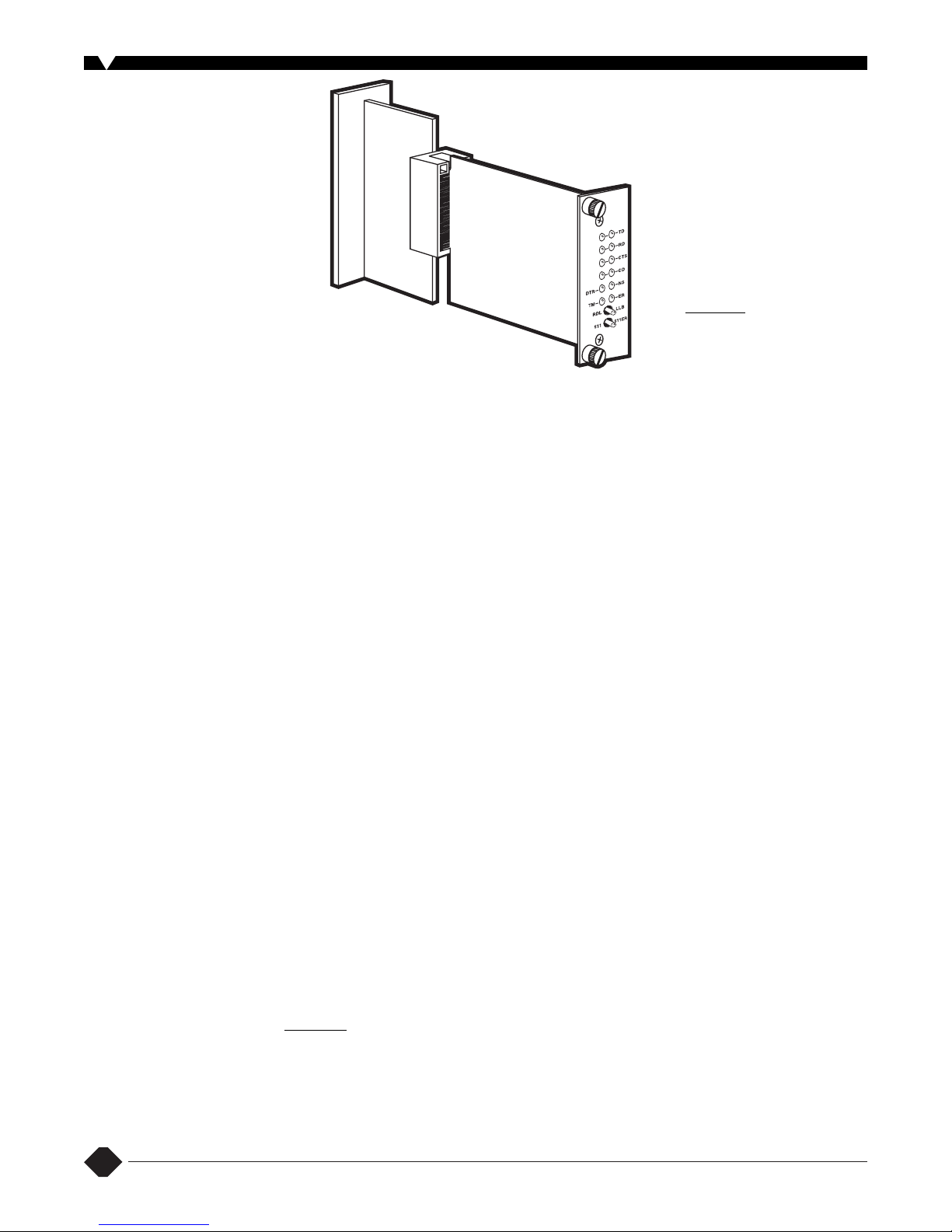
A Managed MicroRACK Card
includes front and rear cards that
snap together inside the 16-Port
Managed MicroRACK chassis.
(continued on page 3)
Page 3

3
2-Wire iDSL Line Drivers
Extend your distances by using
four wires instead of two. This iDSL
(ISDN DSL) card supports highspeed operation on single or dual
copper pairs. Specifically, it enables
synchronous or asynchronous data
to be transmitted point-to-point up
to 10 mi./16.1 km over one or two
twisted pair (2- or 4-wire).
Supporting synchronous speeds
up to 128 kbps and asynchronous
speeds up to 38.4 kbps, the card
is perfect for LAN interconnection
or high-speed Internet links.
To compensate for poor line
quality, the iDSL Card supports
2B1Q encoding, automatic
equalization, and auto gain control.
2B1Q line coding lessens crosstalk
between adjacent lines and
improves signal-to-noise ratios.
The card is fully SNMP
manageable using the SNMP/HTTP
Card. As with the hDSL and mDSL
cards, the iDSL Card features
convenient front-panel diagnostic
DIP switches, LEDs that allow for
easy setup, configuration, and
testing, as well as remote digital
loopback and local line loopback
diagnostics.
The 2-Wire iDSL Line Driver
Card can be ordered with interfaces
for V.24, V.35, X.21, 10BASE-T,
G.703/G.704, or RS-530 networks.
For more information,
including details on our
standalone models, request
Product Data Sheet 25845. Our
Tech Support experts are also
ready to answer your questions.
Micro T1 CSU/DSU Cards
With this 4-wire card, you get a
T1/Fractional T1 (FT1) CSU/DSU and
high-speed point-to-point modem in
a single rack card package.
It’s an excellent choice for
terminating leased lines, Frame
Relay backbones, Internet access,
and LAN-to-LAN services. The card
provides digital access to a local
WAN service provider or between
two facilities over a dedicated
4-wire circuit.
Specifically, the Micro T1
CSU/DSU Card terminates T1 or
FT1 lines over a 4-wire RJ-48C
interface. When used to terminate
a T1-dedicated digital circuit, the
card supports n x 56 kbps and n x 64
kbps framing for T1 and 10BASE-T
Ethernet, V.35, and RS-530
(continued from page 2)
interfaces. Each of these options
supports one DTE interface
connection and one 4-wire line
connection.
A full range of system and
diagnostic features make setup
simple and easy. The card
supports D4/ESF framing options
and AMI/B8ZS/B7ZS line coding.
You can set framing, line coding,
and aggregate bandwidth plus
initiate remote digital loopbacks
and local line loopbacks as well
as send test patterns.
Use the four easily accessible
DIP switches to program the card‘s
data rates, framing, and coding
options. You can also perform these
functions using a menu-driven
VT100
™
terminal, which connects
via the card’s software control port.
Just order a Control Module, which
installs alongside the Micro T1
CSU/DSU Card in the 16-Port
Managed MicroRACK.
SNMP/HTTP Card
The SNMP/HTTP Card is the
perfect complement to the function
cards and 16-Port Managed
MicroRACK. It comes with userfriendly management software that
enables an operator to control the
rack from anywhere in the world via
the Internet.
Once it’s installed in the 16-Port
Managed MicroRACK, you can use
an SNMP workstation to configure
and monitor a number of
interconnected MicroRACKs, the
cards installed in them, and any
remote units linked to modem and
line driver cards.
The card functions as an SNMP
proxy agent for other MicroRACK
cards and their remote standalone
units. Once it’s fully booted, the
SNMP/HTTP Card polls the system,
looking for modems, line drivers,
and other function cards.
The SNMP/HTTP Card supports
generic SNMP management
software and MIB-walking tools.
Alternatively, you can use a
standard Web browser to access
the card’s embedded HTML
management screens.
The SNMP/HTTP Card can
be connected to an SNMP
workstation through a 10BASE-T
Ethernet. And, by making an FTP
connection to the card, you can use
its modular RJ-45 10BASE-T port for
flash upgrades.
To use the card, you’ll not only
need a VT100 terminal or VT100
terminal emulator but also a null-
(continued on page 4)
Standalone
mDSL Modem
(ME0008A)
Management
Station
Router
CSU/DSU
Internet
CSU/DSU
Router
LAN
16-Port Managed
MicroRACK (RM260)
chassis #2 through #4,
each with a Control
Module (RM262C)
Standalone iDSL
modem
(ME0009A-IDSL)
2-Wire iDSL
Line Driver
(ME0001C)
Standalone hDSL
Modem (ME0007A)
Daisychain
connection from
SNMP/HTTP Card
to Control Module
16-Port Managed MicroRACK
(RM260) chassis #1 with
SNMP/HTTP Card (RM261C-SNMP)
10BASE-T
connection to
SNMP/HTTP Card
DSL connection
to mDSL Card
(ME0004C) in
Rack
2B1Q connection to hDSL
Card (ME0003C) in Rack
The SNMP/HTTP Card uses a 10BASE-T Ethernet port
to connect to a local LAN or to anywhere in the world
through the Internet. Management can be performed
using any standard SNMP station or using a standard
Web browser with the card’s internal HTML management
screens. As shown in this diagram, the card can manage
multiple MicroRACKs full of modems, line drivers, etc.,
using a simple daisychain connection and a Control
Module (RM262C) in each managed rack.
Application
Example
Page 4

4
Specifications
MicroRACK
Compliance:
CE; FCC Part 15, Class A
Connectors:
(6) card-edge contacts
for each of (17) card slots (male
toward front cards, female toward
rear cards), plus (2) sets of (10)
female card-edge contacts for
power supplies
Operating Temperature Tolerance:
32 to 122°F (0 to 50°C)
Humidity Tolerance:
Up to 90%
noncondensing
Power:
From one or two cardmount
power supplies, either AC or DC
input (comes with one supply
installed)
Size:
3.5"H (3U) x 19"W x 7.25"D
(8.9 x 48.3 x 18.4 cm)
Weight:
6.6 lb. (3 kg)
Power Supplies
PS466A, PS466A-DC
Compliance:
Both: CE; FCC Part 15
Subpart B Class A, IC Class/
classe A;
PS466A: NRTL, UL
®/
1950, CSA 950,
EN 60950
Input:
PS466A: 90–264 VAC (115 or
230 VAC nominal), 47–63 Hz;
PS466A-DC: -42 to -60 VDC
(-48 VDC nominal)
Output:
To midplane bus at 75%
voltage: 12.3 to 12.5 VDC (12.4 VDC
nominal); Power: 72 watts,
continuous; efficiency (at full load,
with 115-VAC input for PS466A or
-48-VDC input for PS466A-DC): 78%
minimum, 88% maximum
modem cable for connecting the
terminal to the card. Also be sure to
have a 10BASE-T connection from
your local LAN, a locally connected
workstation that you can use to
ping and HTTP into the card, and an
IP address for the card. In addition,
you’ll need the network’s space and
submask and the IP address for the
default gateway of your LAN.
Control Module
This Control Modules enable
you to daisychain up to eight
16-Port Managed MicroRACKs
and control them all.
With a Control Module installed
in each of the racks, you have total
control of up to 120 installed DSL
modem, line driver, or fiber modem
or CSU/DSU cards! What’s more,
you can manage the 120 remote
modem/line drivers as well.
Installed in the 16-Port
Managed MicroRACK, the module
is used to control the rack’s other
cards from an asynchronous
RS-232 terminal or a computer
running terminal emulation.
Supporting terminal data rates to
19.2 kbps, the Control Module has a
modular port for connection to the
RS-232 terminal, and a serial port for
daisychaining between racks.
When you want to reach or
configure a particular function card,
simply key in an addressable
command, which the Control
Module passes along to all the
function cards in the rack. The
appropriate card recognizes its
address and responds to the
command.
As with the 16-Port Managed
MicroRACK’s function cards, the
Control Module consists of a front
card and a rear card that meet in
the middle of the rack. The rear
card has two modular 10-pin RJ
jacks (labeled Port A1) for
connection to the RS-232 terminal.
If the Control Module is being used
in a daisychained application, the
module’s
Port B1
provides the link
to the next Control Module in the
chain.
Wiring a local Control Module
for a daisychain connection
requires the use of two straightthrough modular cables. One cable
connects the serial port of the
RS-232 terminal to Port A1 of the
chain’s first Control Module; and the
second connects Port B1 of the
chain’s first module to Port A1 of the
chain’s second module. You would
use the same cabling procedure to
connect the second module to a
third module, and so on if there are
additional modules in the chain.
(continued from page 3)
User Controls:
(1) midplane-mounted
jumper to select maintenance mode
(no alarm if power supply is
removed)
Connectors:
PS466A: (1) IEC-320, 3-pin
alarm; PS466A-DC: (3) screw
terminals, 3-pin alarm
Indicators:
(3) LEDs for normal
operation, power failure, excessive
internal temperatures
Temperature Tolerance:
Operating:
32 to 122°F (0 to 50°C) at up to 100%
load; above 122˚F (50˚C), load
capacity is derated linearly by 2.5%
for each 1.8˚F until a maximum
temperature of 158˚F (70˚C) is
reached at up to 50% load
Humidity Tolerance:
Up to 90%
noncondensing
Size:
Front card: 3.3"H x 1.5"W x 5"D
(8.4 x 3.8 x 12.7 cm);
Rear card: 3.3"H x 1.5"W x 2.25"D
(8.4 x 3.8 x 5.7 cm)
SNMP/HTTP Card
Compliance:
CE; FCC Part 15 Subpart
B Class A, IC Class/classe
Standard:
IEEE 802.3 Ethernet v2
Interfaces:
10BASE-T; EIA/TIA RS-232,
DTE; proprietary Managed
MicroRACK power and data bus
Transmission Format:
RS-232:
Asynchronous
Data Format:
RS-232: 8 data bits, no
parity, 1 stop bit (fixed)
Data Rate:
10BASE-T: 10 Mbps;
RS-232: 19,200 bps (fixed)
Flow Control:
RS-232: Responds to
CTS (hardware) flow control only
Maximum Distance:
10BASE-T:
328 ft. (100 m) to next device;
RS-232: 50 ft. (15.2 m) to next
device
User Controls:
RS-232 terminal
session console (requires VT100
™
or compatible terminal emulation);
internal HTML management pages
accessible through Ethernet
network
Indicators:
(9) LEDs: Power, (2) TD
(Transmit Data), (2) RD (Receive
Data), LI (Link Integrity), PPP (not
supported at this time), Poll (poll
signal), Fault (Fault Detection)
Connectors:
(1) RJ-45 female for
10BASE-T; (1) DB25 female for
RS-232; 50-pin card-edge on both
front and rear cards
Power:
From one or two cardmount
power supplies, either AC or DC
input (comes with one supply
installed)
Temperature Tolerance:
Operating:
32 to 122˚F (0 to 50˚C)
Humidity Tolerance:
5 to 95%
noncondensing
Size:
Front card: 3.3"H x 1.5"W x 5"D
(8.4 x 3.8 x 12.7 cm);
Rear card: 3.3"H x 1.5"W x 2.25"D
(8.4 x 3.8 x 5.7 cm)
Control Module
Compliance:
CE; FCC Part 15 Subpart
B Class A, IC Class/classe A
Interfaces:
EIA/TIA RS-232,
proprietarily pinned on 10-pin RJ
connectors in a manner similar to
EIA/TIA-561; port A1 is DCE, port B1
is DTE; proprietary Managed
MicroRACK power and data bus
Transmission Format:
Asynchronous
Data Format:
Transparent to data
format (data bits, stop bits, and
parity)
Data Rate:
Transparent to data rates
up to 19.2 kbps
Flow Control:
Transparent to
software flow control; RS-232
hardware flow-control leads are
always ON (for continuous
transmission)
User Controls:
(5) rear-card jumpers:
(1) for signal ground/frame ground
connection or isolation; (4) not used
Indicators:
(5) LEDs: Power, (2) TD
(Transmit Data), (2) RD (Receive
Data)
Connectors:
(2) 10-pin RJ female:
(1) for output to terminal or another
module (Port A1, DCE); (1) for input
from another module (Port B1, DTE)
Power:
From one or two cardmount
power supplies, either AC or DC
input (comes with one supply
installed)
Operating Temperature Tolerance:
32 to 122˚F (0 to 50˚C)
Humidity Tolerance:
Up to 95%
noncondensing
Size:
Front card: 3.3"H x 1.5"W x 5"D
(8.4 x 3.8 x 12.7 cm);
Rear card: 3.3"H x 1.5"W x 2.25"D
(8.4 x 3.8 x 5.7 cm)
Page 5

5
Interface Cards
All
Compliance:
All cards: CE;
ME911C cards: FCC Part 15 Class A
and Part 68;
All except ME911C cards: FCC
Part 15 Subpart B, Class A
IC Class/classe A; CTR 12
Clocking:
Internal, external, or receive
recovered clock
Temperature Tolerance:
Operating:
32 to 122˚F (0 to 50˚C)
Humidity Tolerance:
5 to 95%
noncondensing
Power:
From the rack power
module(s)
G.703 /E1 Fiber Cards
Transmission Format:
Synchronous
Data Rates:
2.048 Mbps on both line
and network interfaces
Line Coding:
Network: AMI or HDB3;
Fiber line: 8B10B
Transmission Line:
Full-duplex on
fiber
Transmitter Launch Power:
ME400C: 0 dBm;
ME401C: 0 to -10 dBm
Receiver Sensitivity:
18 dBm
Optical Budget:
ME400C: 7.5 dB;
ME401C: 0 to -10 dBm
Maximum Coupling Loss:
1.5 dB per
connector
Maximum Distance:
Network cabling
from card to next device: 1 mi.
(1.6 km) of 24 AWG wire;
Fiber between (2) cards:
ME400C: 850 nm: 2.5 km (1.5 mi.);
ME401C: 1310 nm: 50 km (31 mi.)
User Controls:
(2) front-mounted
toggle switches for loopback and
BER testing; (1) 8-position DIP
switch for clock source and line
coding (board-mounted on front
card); (4) jumpers for networkinterface type (board-mounted on
rear card)
Specifications
Diagnostics: ITU V.54-compliant
local
(to G.703/G.704 network) or
remote (to fiber line) loopback
testing; ITU V.52-compliant 511/511E
BER testing
Connectors:
All: (1) RJ-48C for
120-ohm twisted-pair;
(2) BNC female ([1] TX, [1] RX) for
75-ohm coaxial;
ME400C-ST: (1) ST female for fiber;
ME401C-FC: (1) FC female for fiber;
ME401C-SC: (1) SC female for fiber;
matching 50-pin card-edge
connectors on front and rear
cards
Leads/Signals Supported:
RJ-48C:
Pins 1, 2, 4, 5 (Rx+, Rx-, Tx+, and Txrespectively)
Isolation:
G.703/G.704 interface:
Transformer coupled, 1500 VAC
RMS
Size:
Front card: 3.1"H x 0.95"W x 4.8"D
(7.9 x 2.4 x 12.2 cm);
Rear card: 3.3"H x 0.95"W x 2.25"D
(8.4 x 2.4 x 5.7 cm)
2-Wire Short-Range mDSL Cards
Transmission Format:
Synchronous
Transmission Line:
Two-wire
unconditioned twisted pair
Maximum Distance:
3.6 mi. (5.8 km)
Line Rates:
144, 272, 400, 528, 784,
1040, 1552, 2064, and 2320 kbps
DTE Rates:
64 to 2304 kbps in 64-kbps
steps
Diagnostics:
V.52-compliant bit error
rate pattern (511/511E pattern)
generator and detector with error
injection mode; local line loopback
and remote digital loopback,
activated by front-panel switch
or via serial interface
Connectors:
Line side: All: RJ-45;
Interface side: DB25 female, M/34
female, DB15 female, RJ-45, or
dual BNC, depending upon
module installed
Size: Front
Card: 3.1"H x 0.95"W x 4.8"D
(7.9 x 2.4 x 12.2 cm);
Rear Card: 3.3"H x 0.95"W x 2.8"D
(8.4 x 2.4 x 7.1 cm)
2-Wire Short-Range hDSL Cards
Transmission Format:
Synchronous
Transmission Line:
Two-wire
unconditioned twisted pair
Line Rates:
144, 272, 400, 528, 784,
1040, and 1168 kbps
DTE Rates:
64 to 1152 kbps in 64-kbps
steps
Diagnostics:
V.52-compliant bit error
rate pattern (511/511E pattern)
generator and detector with error
injection mode; local line loopback
and remote digital loopback,
activated by front-panel switch
or via serial interface
Connectors:
Line side: All: RJ-45;
Interface side: DB25 female, M/34
female, DB15 female, RJ-45, or
dual BNC, depending upon
module installed
Size:
Front card: 3.1"H x 0.95"W x 4.8"D
(7.9 x 2.4 x 12.2 cm);
Rear card: 3.3"H x 0.95"W x 2.8"D
(8.4 x 2.4 x 7.1 cm)
2-Wire iDSL Cards
Transmission Format:
Synchronous
or asynchronous
Transmission Line:
One- or two-pair
unconditioned twisted wire
Maximum Distance:
10.8 mi. (17.4 km)
DTE Rates
: Synchronous: 19.2, 32, 56,
64, and 128 kbps;
Asynchronous: Up to 38.4 kbps
Line Rates:
128 kbps
Diagnostics:
V.52-compliant bit error
rate pattern (511/511E pattern)
generator and detector with error
injection mode; local line loopback
and remote digital loopback,
activated by front-panel switch or
via serial interface
Connectors:
Line side: All: RJ-45;
Interface side: DB25 female, M/34
female, DB15 female, RJ-45, or
dual BNC, depending upon
module installed
Size:
Front card: 3.1"H x 0.95"W x 4.8"D
(7.9 x 2.4 x 12.2 cm);
Rear card: 3.3"H x 0.95"W x 2.8"D
(8.4 x 2.4 x 7.1 cm)
Micro T1 CSU/DSU Cards
Transmission Format:
T1 AMI or
B8ZS line coding
DTE Rates:
64, 128, 192, 256, 320, 384,
448, 512, 576, 640, 704, 768, 832, 896,
960, 1024, 1088, 1152, 1216, 1280,
1344, 1408, 1472, and 1536 kbps
WAN Speed:
1.544 Mbps
(unstructured)
Connectors:
On line side: RJ48C;
Interface side: DB25 female, M/34
female, or RJ-45, depending
upon module installed
Diagnostics:
Responds to CO-initiated
D4 loopup and loopdown codes,
ESF line loop and payload loop FDL
messages, universal loopback
deactivate message
Size:
Front card: 3.1"H x 0.95"W x 4.8"D
(7.9 x 2.4 x 12.2 cm);
Rear card: 3.3"H x 0.95"W x 2.8"D
(8.4 x 2.4 x 7.1 cm)
Page 6

6
Ordering Information
ITEM CODE
16-Port Managed MicroRACK...................................RM260
Choose your power supply card:
NOTE: RM260 comes with (1) AC power supply front and back card.
AC Power Supply (90 to 260 VAC)
for Redundancy........................................................PS466A
DC Power Supply (-48 VDC)...............................PS466A-DC
Choose the interface cards for your application…
G.703/E1 Fiber Line Driver Cards
Multimode with ST
®
Connectors ..............ME400C-ST
Single-Mode with FC Connectors ............ME401C-FC
with SC Connectors ..........ME401C-SC
2-Wire Short-Range DSL Line Driver Cards
mDSL
V.24 (DB25 F)..............................................ME0004C-V24
V.35 (M/34 F) ..............................................ME0004C-V35
X.21 (DB15 F) .............................................ME0004C-X21
10BASE-T (RJ-45)..................................ME0004C-10BT
G.703/G.704 (Dual BNC or RJ-45).......ME0004C-G703
RS-530 (DB25 F) ...................................ME0004C-RS530
hDSL
V.24/V.35 (DB25 F).....................................ME0003C-V24
V.35 (M/34 F) ..............................................ME0003C-V35
X.21 (DB15 F) .............................................ME0003C-X21
10BASE-T (RJ-45)..................................ME0003C-10BT
G.703/G.704 (Dual BNC or RJ-45).......ME0003C-G703
RS-530 (DB25 F) ...................................ME0003C-RS530
ITEM CODE
2-Wire idSL Line Drivers
V.24 (DB25 F)..................................................ME0001C-V24
V.35 (M/34 F) ..................................................ME0001C-V35
X.21 (DB15 F)..................................................ME0001C-X21
10BASE-T (RJ-45)......................................ME0001C-10BT
G.703/G.704 (Dual BNC or RJ-45)...........ME0001C-G703
RS-530 (DB25 F) .......................................ME0001C-RS530
Micro T1 CSU/DSU Cards
10BASE-T (RJ-45)........................................MT911C-10BT
V.35 (M/34 F) .......................................................MT911C-35
RS-530 (DB25 F)...............................................MT911C-530
T
o protect unpopulated rack ports, order…
Blank Panels
Front Panel 1", 1-Slot Wide.......................O1OZ20885
4", 4-Slot Wide.......................O1OZ20887
Rear Panel 1", 1-Slot Wide.......................O1OZ20888
4", 4-Slot Wide.......................O1OZ20889
Bag of (16) Screws for Blank Panels.................Z1Z184566
For additional management capabilities, order…
SNMP/HTTP Card........................................RM261C-SNMP
T
o control daisychained racks, order…
Control Module ...........................................................RM262C
 Loading...