

Page 1
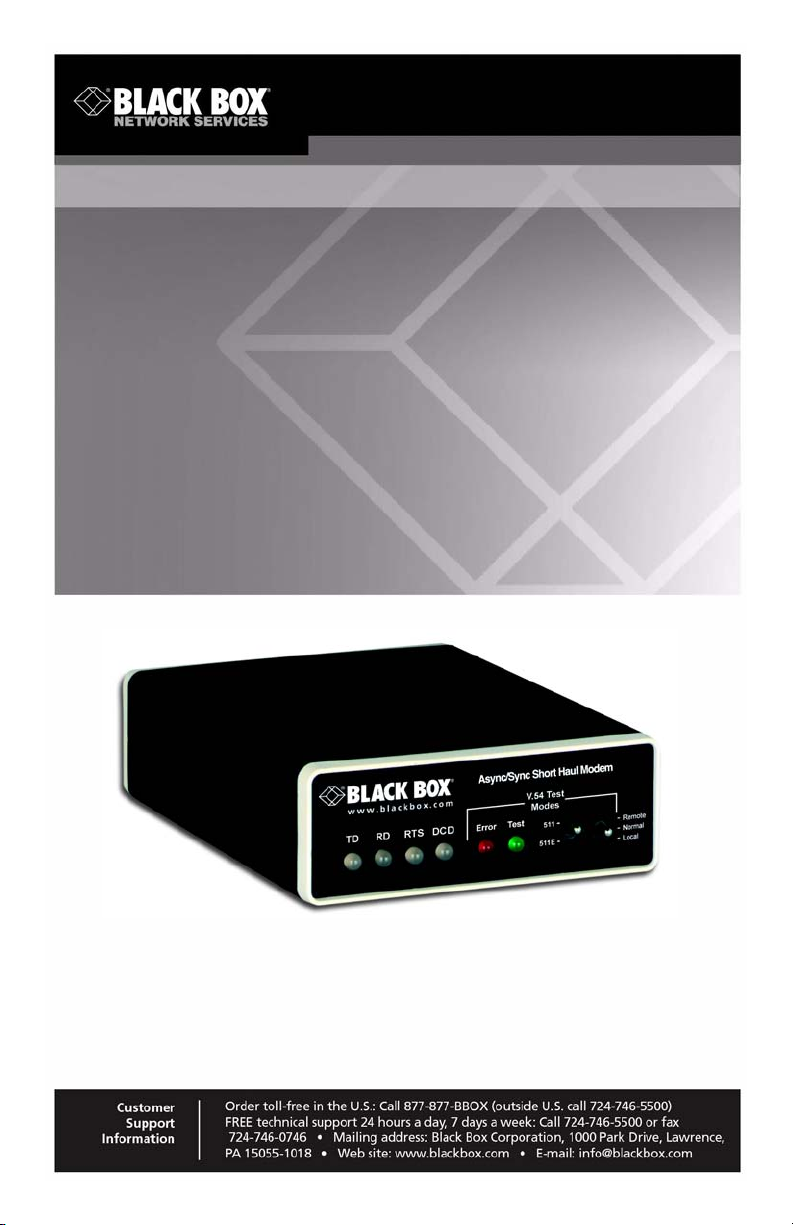
Async/Sync Short-Haul Modem
ME475A-R2
Page 2

Black Box Short Range Modem
TABLE OF CONTENTS
1. General Information ..........................................................................................5
1.1 Features ................................................................................................5
1.2 Description ............................................................................................5
2. Configuration Overview ....................................................................................6
2.1 Configuration Switches .........................................................................6
2.2 Configuration Switch Set “S1” ...............................................................7
Switches S1-1 through S1-4: Data Rate Setting .................................7
Switches S1-5 and S1-6: Clock Source ..............................................8
Switch S1-7: Asynchronous/Synchronous Mode ................................8
Switch S1-8: Carrier Control Method ..................................................9
2.3 Configuration Switch Set “S2” ...............................................................9
Switches S2-1 and S2-2: Word Length .............................................10
Switch S2-3: Extended Signaling Rate .............................................10
Switches S2-4 and S2-5: RTS/CTS Delay ........................................10
Switch S2-6: V.54 Loopback Test Enable ........................................11
Switch S2-7: 2-Wire/4-Wire Mode Selection .....................................11
2.4 Configuration Switch Set “S3” .............................................................11
Switches S3-1 & S3-2: Input Impedance ..........................................11
Switch S3-4: Mode Selection ............................................................12
Switch S3-5: RS-232 Initiation of Local Loopback Test ....................12
Switch S3-6: RS-232 Initiation of Remote Loopback Test ................13
Switches S3-7 and S3-8: Anti-stream Control ..................................13
3. Installation .......................................................................................................13
3.1 Two-wire Installation ...........................................................................14
Two-Wire Cable Connection Via RJ-45 ............................................14
Two-Wire Cable Connection Via Terminal Blocks ............................15
3.2 Four-wire Installation ..........................................................................16
Four-Wire Cable Connection Via RJ-45 ...........................................16
Four-Wire Cable Connection Via Terminal Blocks ...........................17
3.3 Four-wire, Multipoint Installation .........................................................18
Multipoint Twisted Pair Connection ..................................................19
3.4 RS-232 Connection ............................................................................20
4. Operation ........................................................................................................21
4.1 LED Status Monitors ...........................................................................21
The “TD” and “RD” Indicators ...........................................................21
The “RTS” and “CD” Indicators .........................................................21
The “Test” Indicator ..........................................................................21
The “Error” Indicators ........................................................................22
4.2 Anti-Streaming Error Indicator ............................................................23
4.3 Power-up ............................................................................................23
Page 2
724-746-5500 | blackbox.com
Page 3

4.4 V.54 Test Modes ................................................................................ 23
Local Analog Loopback (LAL) .......................................................... 24
Remote Digital Loopback (RDL) ....................................................... 24
Using the V.52 BER Test Independently .......................................... 25
4.5 Power-down .......................................................................................25
A. Specifications ................................................................................................. 26
A.1 Transmission Format .......................................................................... 26
A.2 Interface .............................................................................................. 26
A.3 Transmission Line ...............................................................................26
A.4 Data Rates .......................................................................................... 26
A.5 Clocking .............................................................................................. 26
A.6 Controls ............................................................................................... 26
A.7 Applications ......................................................................................... 26
A.8 Indicators ............................................................................................ 26
A.9 RTS Anti-stream Timer ....................................................................... 26
A.10 Diagnostics ....................................................................................... 27
A.11 Transformer Isolation ........................................................................27
A.12 Surge Protection ............................................................................... 27
A.13 Temperature .....................................................................................27
A.14 Humidity ............................................................................................ 27
A.15 Dimensions ....................................................................................... 27
A.16 Power Input (US) .............................................................................. 27
B. Cable Recommendations ...............................................................................28
C. Interface Pin Assignment ............................................................................... 30
D. Black Box ME475A-R2 Block Diagram .......................................................... 31
724-746-5500 | blackbox.com
Page 3
Page 4

Black Box Short Range Modem
WARRANTY INFORMATION
Black Box warrants all ME475A-R2 components to be free from defects, and will—at
our option—repair or replace the product should it fail within one year from the first
date of the shipment.
This warranty is limited to defects in workmanship or materials, and does not cover
customer damage, abuse or unauthorized modification. If this product fails or does not
performs as warranted, your sole recourse shall be repair or replacement as described
above. Under no condition shall Black Box be liable for any damages incurred by the
use of this product. These damages include, but are not limited to, the following: lost
profits, lost savings and incidental or consequential damages arising from the use of or
inability to use this product. Black Box specifically disclaims all other warranties,
expressed or implied, and the installation or use of this product shall be deemed an
acceptance of these terms by the user.
RADIO AND TV INTERFERENCE
The ME475A-R2 generates and uses radio frequency energy, and if not installed and
used properly—that is, in strict accordance with the manufacturer’s instructions—may
cause interference to radio and television reception. The ME475A-R2 has been tested
and found to comply with the limits for a Class A computing device in accordance with
specifications in Subpart B of Part 15 of FCC rules, which are designed to provide rea
sonable protection from such interference in a commercial installation. However, there
is no guarantee that interference will not occur in a particular installation. If the l
ME475A-R2 does cause interference to radio or television reception, which can be
determined by disconnecting the RS-232 interface, the user is encouraged to try to
correct the interference by one or more of the following measures: moving the computing equipment away from the receiver, re-orienting the receiving antenna and/or plugging the receiving equipment into a different AC outlet (such that the computing
equipment and receiver are on different branches).
-
CE NOTICE
The CE symbol on your Black Box equipment indicates that it is in compliance with the
Electromagnetic Compatibility (EMC) directive and the Low Voltage Directive (LVD) of
the European Union (EU). A Certificate of Compliance is available by contacting Technical Support.
Page 4
724-746-5500 | blackbox.com
Page 5

1. GENERAL INFORMATION
Thank you for your purchase of this Black Box product. This product has been thoroughly inspected by Black Box’s qualified technicians. If any questions or problems
arise during installation or use of this product, please do not hesitate to contact Black
Box Technical Support at 724-746-5500 or [email protected].
1.1 FEATURES
• Synchronous or asynchronous operation
• Supports data rates up to 57.6 kbps
• Two-wire/half duplex or four-wire/full or half duplex
• V.52 & V.54 test modes
• Automatic equalization & gain control
• Anti-streaming timer
• Distances up to 20 miles (32 km)
• Point-to-point or multipoint
• Internal, external or received loopback clocking
• Hardware and software flow control support
• Built-in transformer isolation & high speed surge protection
• External AC power
• Bi-color LED indicators
• Detects broken or inferior cable by lighting error LED
1.2 DESCRIPTION
The ME475A-R2 Universal Short Range Modem operates 2-wire (half duplex) or 4wire (full or half duplex), in synchronous or asynchronous modes, over unconditioned
telephone lines. The ME475A-R2 supports bit rates up to 57.6 kbps. The ME475A-R2
operates in synchronous mode between the local and remote modems; when con
nected to an asynchronous RS-232 device, the ME475A-R2 SRM converts the asynchronous data to synchronous data.
The ME475A-R2 has several features to enhance overall performance: automatic
equalization, automatic gain control, anti-streaming timer, transformer isolation to
guard against data loss due to ground potential differences, and Silicon Avalanche
Diode surge protection to guard against data line transients.
724-746-5500 | blackbox.com
-
Page 5
Page 6
Black Box Short Range Modem
12345678
ON
12345678
ON
12345678
ON
FRONT
REAR
S1
S2
S3
ON
OFF
The ME475A-R2 features V.52 compliant bit error rate pattern tests and two V.54 test
modes: local analog loopback and remote digital loopback. The operator at the local
end may test both local and remote modems, plus the line, in the digital loopback
mode. Both RDL and LAL modes can be controlled by a manual switch or via the
V.24/RS-232 interface.
2. CONFIGURATION OVERVIEW
The ME475A-R2 is fairly simple to install and is ruggedly designed for excellent reliability: just set it and forget it. The following instructions will help you set up and install
the ME475A-R2 properly.
2.1 CONFIGURATION SWITCHES
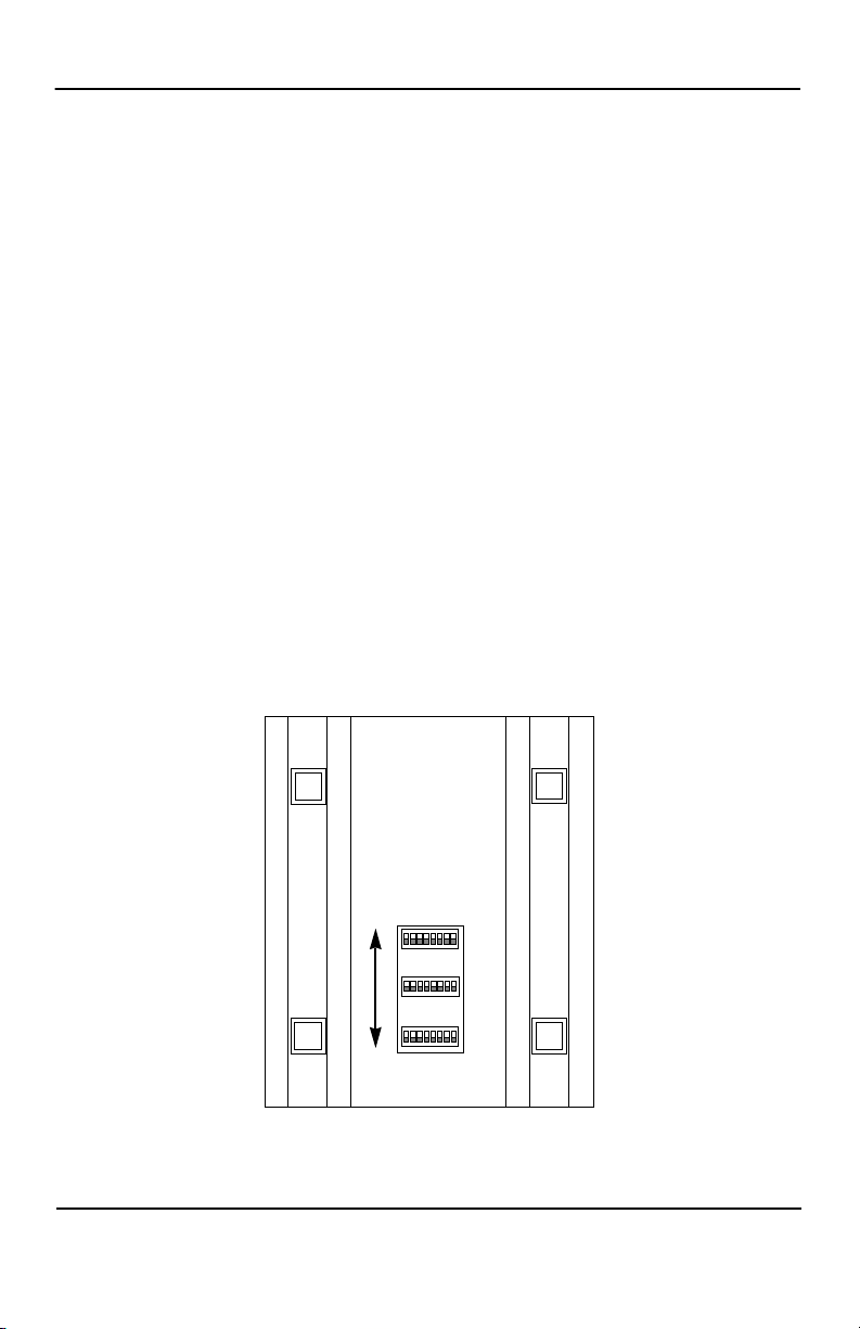
The ME475A-R2 uses a unique set of 24 external mini DIP switches that allow configuration to an extremely wide range of applications. These 24 DIP switches are
grouped into three eight-switch sets, and are externally accessible from the underside
of the unit (see Figure 1). Since all configuration DIP switches are externally accessible, there is no need to open the case for configuration.
The configuration switches allow you to select data rates, clocking methods, V.52 &
V.54 tests, word lengths, extended signaling rates, async. or sync. mode, 2- or 4-wire
operation, anti-stream control and input impedance. The drawings, text and tables on
the following pages describe all switch locations, positions and functions.
Page 6
Figure 1. Underside of ME475A-R2, showing location of DIP switches
724-746-5500 | blackbox.com
Page 7
Configuration Overview
OFF
ON
12345678
ON
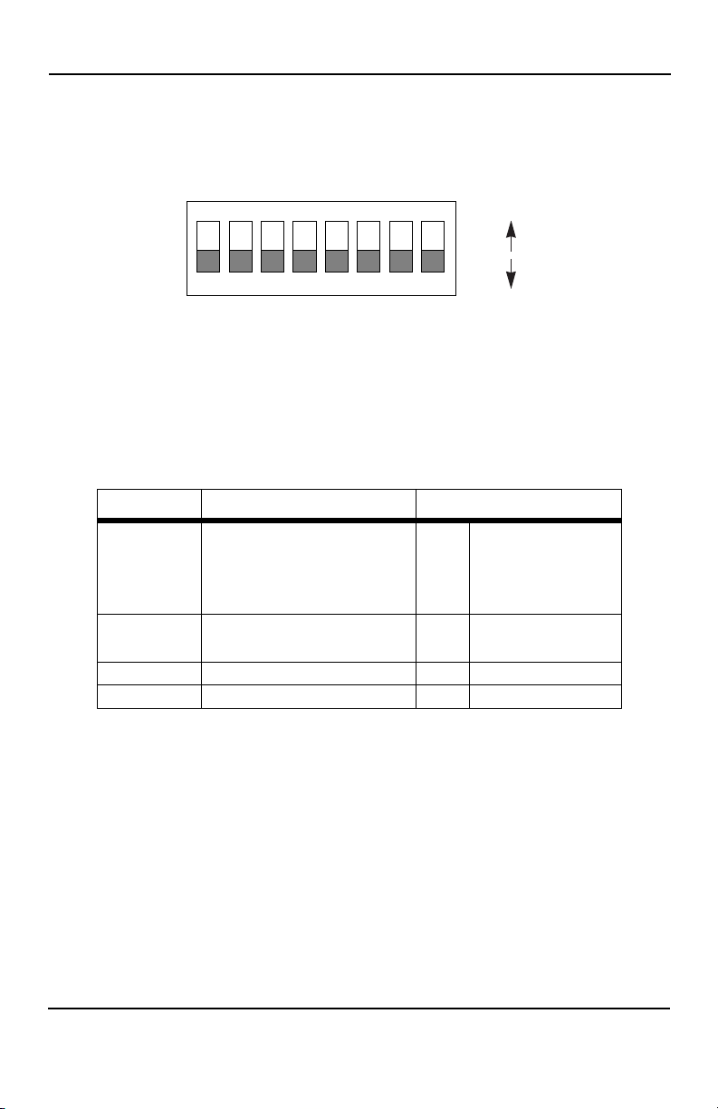
Each ME475A-R2 SRM has three sets of eight switches, yielding 24 total DIP
switches. The three sets will be referred to as S1, S2 and S3. As
orientation of all DIP switches is the same with respect to “ON” and “OFF” positions.
Figure 2. Close-up of DIP switches showing “ON” and “OFF” positions
2.2 CONFIGURATION SWITCH SET “S1”
The DIP switches on S1 set data rate, clock source, async./sync. mode and carrier
control method. The default settings are summarized in
Table 1: ME475A-R2 S1 Summary
Position Function Factory Default
S1-1
S1-2 Off
S1-3 Off
S1-4 On
S1-5
S1-6
S1-7 Async./Sync. On Async.
S1-8 Carrier Control Off Constantly On
Data Rate
Clock Source On Internal
Table 1.
On
Figure 2 shows, the
9,600 bps
(ME465A-R2)
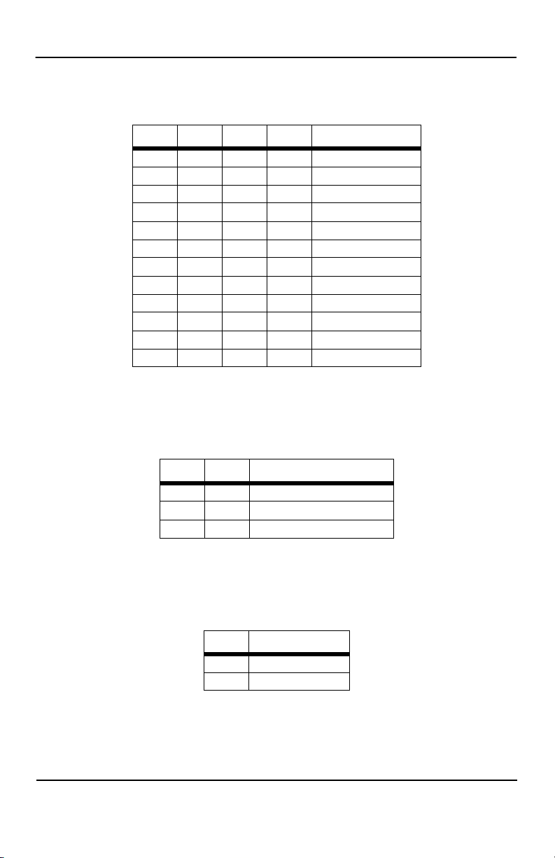
Switches S1-1 through S1-4: Data Rate Setting
Switches S1-1 through S1-4 are set in combination to determine the asynchronous
and synchronous data rate for the ME475A-R2.
724-746-5500 | blackbox.com
Page 7
Page 8
Black Box Short Range Modem
Shown in the tables below are the Data Rate DIP Switch settings for ME475A-R2.
Tab le 2: ME475A-R2 Data Rate Settings
S1-1 S1-2 S1-3 S1-4 Setting
On On On On 1.2 kbps
Off On On On 1.8 kbps
On Off On On 2.4 kbps
Off Off On On 3.6 kbps
On On Off On 4.8 kbps
Off On Off On 7.2 kbps
On Off Off On 9.6 kbps
Off Off Off On 14.4 kbps
On On On Off 19.2 kbps
Off On On Off 28.8 kbps
On On Off Off 38.4 kbps
Off On Off Off 57.6 kbps
Switches S1-5 and S1-6: Clock Source
Switches S1-5 and S1-6 are set in combination to determine the transmit clock source
for the ME475A-R2.
S1-5 S1-6 Setting
On On Internal transmit clock
Off On Receive recover clock
On Off External transmit clock
Switch S1-7: Asynchronous/Synchronous Mode
The setting for switch S1-7 determines whether the ME475A-R2 is in asynchronous or
synchronous operating mode.
S1-7 Setting
On Asynchronous
Off Synchronous
Page 8
724-746-5500 | blackbox.com
Page 9
Configuration Overview
Switch S1-8: Carrier Control Method
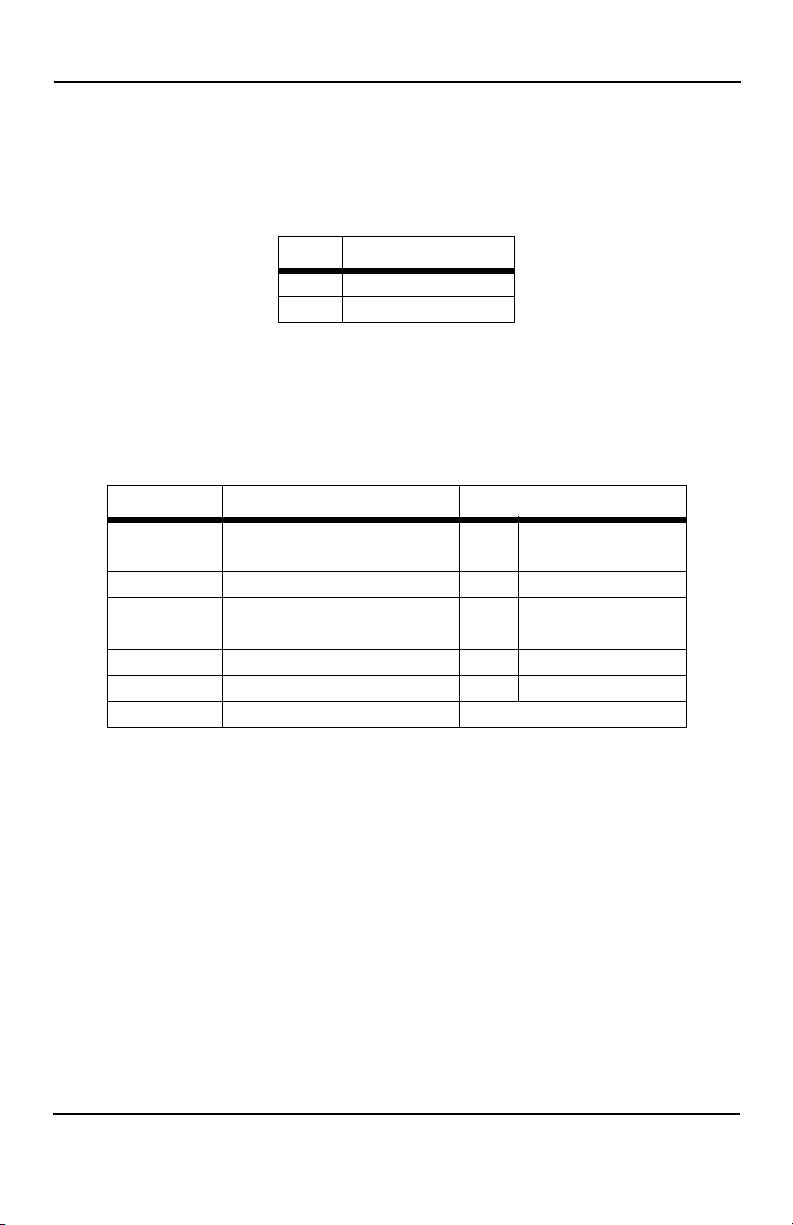
The setting for switch S1-8 determines whether the carrier is “constantly on” or “controlled by RTS”. This setting allows for operation in switched carrier, multipoint and/or
hardware handshaking applications.
S1-8 Setting
Off Constantly on
On Controlled by RTS
2.3 CONFIGURATION SWITCH SET “S2”
The DIP switches on S2 set word length, extended signaling rate, RTS/CTS delay,
V.52 and V.54 diagnostic test and 2- and 4-wire operation.
Tab le 3: S2 Summary
Position Function Factory Default
S2-1
S2-2
S2-3 Extended Signalling Rate Off -2.5% to 1%
S2-4
S2-5
S2-6 V.52/V.54 Tests Off Normal Operation
S2-7 2-Wire/4-Wire Off (4-Wire)
S2-8 Not Used N/a
Word Length Off 10 bits
RTS/CTS Delay On 7 ms
724-746-5500 | blackbox.com
Page 9
Page 10
Black Box Short Range Modem
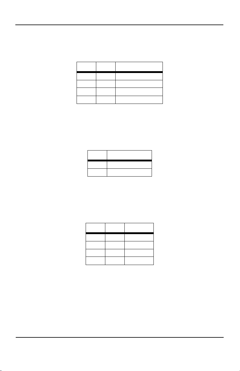
Switches S2-1 and S2-2: Word Length
Switches S2-1 and S2-2 are set in combination to determine the word length for asynchronous data.
S2-1 S2-2 Setting
Off On 8 bits
On On 9 bits
Off Off 10 bits
On Off 11 bits
Switch S2-3: Extended Signaling Rate
The setting for switch S2-3 determines the range of variability the ME475A-R2 “looks
for” in asynchronous data rates (i.e., the actual variance from a given frequency level
the ME475A-R2 will tolerate).
S2-3 Setting
Off -2.5% to +1%
On -2.5% to +2.3%
Switches S2-4 and S2-5: RTS/CTS Delay
The combined settings for switches S2-4 and S2-5 determine the amount of delay
between the time the unit “sees” RTS and when it sends CTS. Options are no delay, 7
ms and 53 ms.
S2-4 S2-5 Setting
On On 7 ms
Off On 53 ms
On Off No delay
Off Off No delay
Page 10
724-746-5500 | blackbox.com
Page 11
Configuration Overview
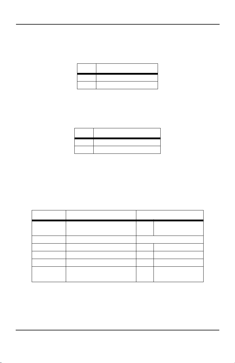
Switch S2-6: V.54 Loopback Test Enable
To reset the V.54 circuit, set switch S2-6 to the “ON” position, then back to the “OFF”
position.
S2-6 Setting
Off V.54 Normal Operation
On V.54 Testing Disabled
Switch S2-7: 2-Wire/4-Wire Mode Selection
The setting for switch S2-7 determines whether the ME475A-R2 is operating in 2-wire
or 4-wire mode.
S2-7 Setting
Off 4-wire (full or half duplex)
On 2-wire (half duplex only)
2.4 CONFIGURATION SWITCH SET “S3”
The DIP switches on S3 set the anti-stream control, local loopback enable, remote
loopback enable and receive (input) impedance levels for the ME475A-R2. Factory
default positions of Switch S3 are shown in the table below:
Tab le 4: S3 Summary
Position Function Factory Default
S3-1
S3-2 Off
S3-3 Not yet assigned N/A
S3-4 Mode Selection On Point to Point
S3-5 Local Loopback Off Disabled
S3-6 Remote Loopback Off Disabled
S3-7
S3-8
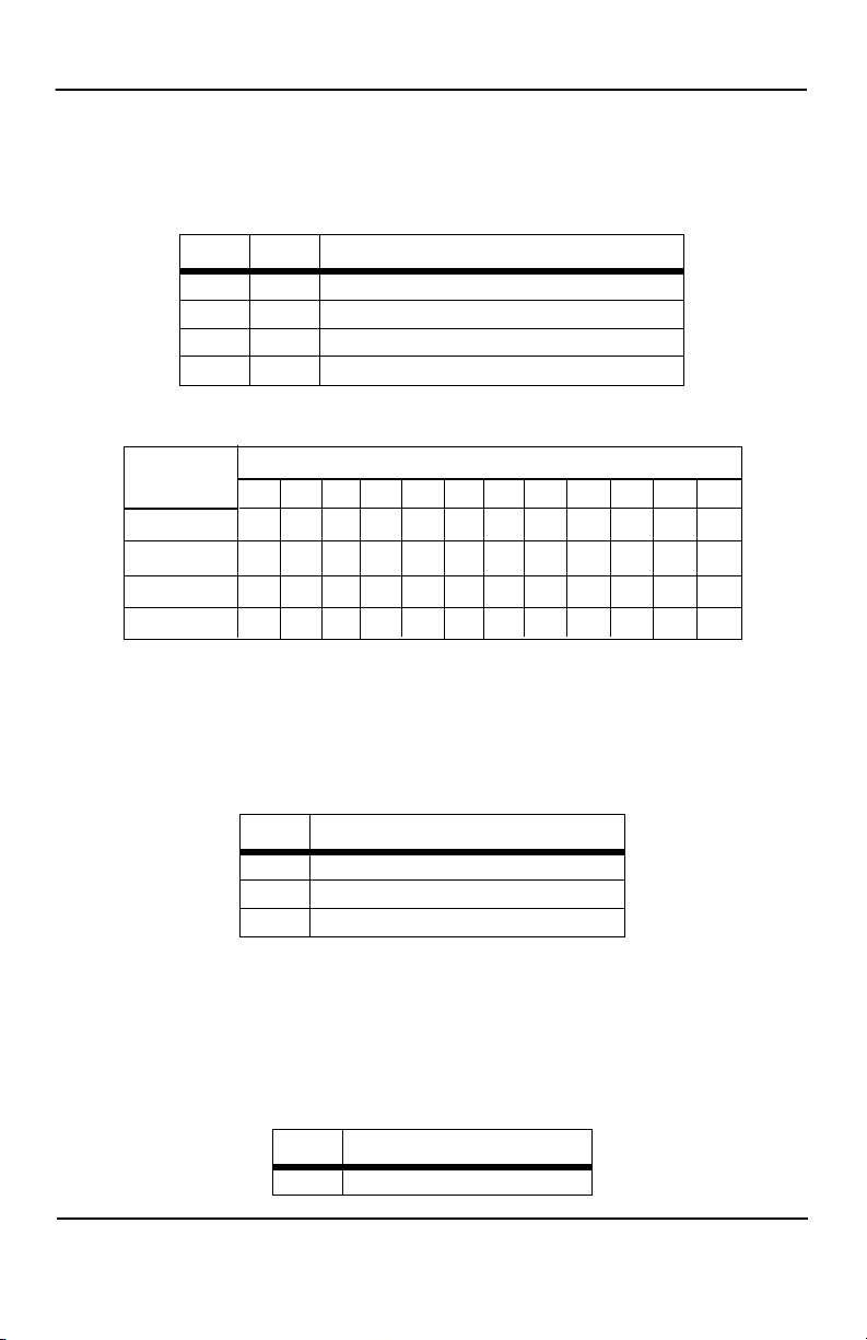
Switches S3-1 & S3-2: Input Impedance
The setting for Switches S3-1 and S3-2 determines the ME475A-R2’s input impedance. This allows you to choose the optimum impedance setting for your application.
In long distance applications the impedance of the cable must match the impedance of
Input Impedance
Anti-stream Control Off Disabled
724-746-5500 | blackbox.com
On
200 ohms
Page 11
Page 12
Black Box Short Range Modem
Gauge of
Cable
19AWG/.9mm
22AWG/.6mm
24AWG/.5mm
26AWG/.4mm
1.2
320
320
320
320
Data Rates, kb/s
1.8
320
320
320
320
2.4
200
320
320
320
3.6
200
200
320
320
4.8
200
200
200
320
7.2
200
200
200
200
9.6
200
200
200
200
14.4
130
200
200
200
19.2
130
130
200
200
28.8
130
130
130
200
38.4
130
130
130
130
57.6
130
130
130
130
the load (or resistor) of the ME475A-R2 unit. Thicker gauge cables requires a lower
ohm setting, while a thinner gauge cable should receive a higher ohm setting. If you
are using higher speeds you will need a lower ohm setting, and a higher ohm setting
for the slower speeds. Refer to
S3-1 S3-2 Setting
On On 130 ohms
On Off 200 ohms
Off On 320 ohms
Off Off High impedance (minimum 2k ohms)
Tab l e 5: S3-1, S3-2 Selection Table for ME475A-R2
Ta bl e 5 for assistance in selecting a setting.
Switch S3-4: Mode Selection
The setting for switch S3-4 allows the user to choose the appropriate setting for pointto-point or multipoint applications.
S3-4 Setting
On Point-to-point
On Multipoint application as “Master”
Off Multipoint application as “Slave”
Switch S3-5: RS-232 Initiation of Local Loopback Test
The setting for switch S3-5 determines whether or not the ME475A-R2’s local analog
loopback test can be initiated by raising pin 18 on the RS-232 interface.
S3-5 Setting
Page 12
On RS-232 initiation enabled
724-746-5500 | blackbox.com
Page 13
Installation
S3-5 Setting
Off RS-232 initiation disabled
Switch S3-6: RS-232 Initiation of Remote Loopback Test
The setting for switch S3-6 determines whether or not the ME475A-R2’s remote digital
loopback test can be initiated by raising pin 21 on the RS-232 interface.
S3-6 Setting
On RS-232 initiation enabled
Off RS-232 initiation disabled
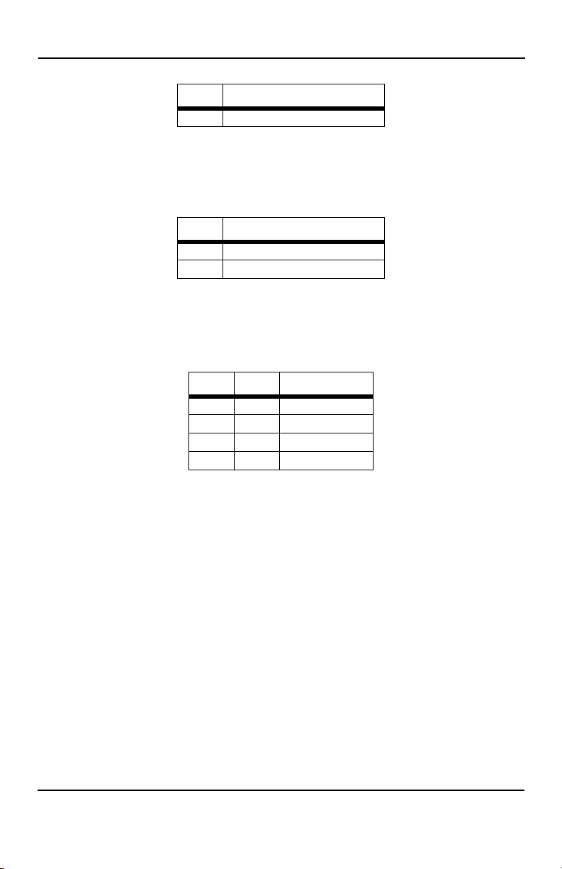
Switches S3-7 and S3-8: Anti-stream Control
Switches S3-7 and S3-8 are set in combination to determine the time out period for the
ME475A-R2’s anti-stream control timer.
S3-7 S3-8 Setting
Off Off Disabled
Off On 12.5 seconds
On Off 50.0 seconds
On On 12.5 seconds
3. INSTALLATION
The ME475A-R2 operates in four twisted pair topologies: 2-wire/point-to-point, 2wire/multipoint, 4-wire/point-to-point, and 4-wire/multipoint. In each of these topolo
gies, the twisted pair wire must be 19 - 26 AWG “dry”, unconditioned metallic wire (see
Appendix C for wire recommendations). Dial-up analog circuits, such as those used
with a standard Hayes-type modem, are not acceptable. The twisted pair may be
shielded or not shielded. Both types yield favorable results.
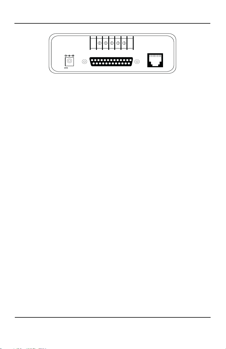
The ME475A-R2 offers two methods of twisted pair connection: RJ-45 jack and terminal blocks. Figure 3 shows the location of these interfaces on the rear panel of the
ME475A-R2. Connect the wire to each ME475A-R2 as described in the instructions
that follow the illustration. The “+” and “-” indicators are for reference only. The
ME475A-R2 is not sensitive to polarity.
724-746-5500 | blackbox.com
-
Page 13
Page 14
Black Box Short Range Modem
RS-232 Interface (Female)
Made In the USA
Line
RX+ RX- GND TX- TX+
12V, 2A
Figure 3. Rear view of ME475A-R2 - AC Power
3.1 TWO-WIRE INSTALLATION
When communicating over a single twisted pair circuit, the ME475A-R2 operates half
duplex: that is, it transmits in only one direction at a time. This method of operation is
effective for both point-to-point and multipoint applications.
In single-pair point-to-point applications, you will need a pair of ME475A-R2s for each
circuit—one at each end of the single pair wire. In single-pair multipoint applications
you will need three or more ME475A-R2 units. These can be connected using a star
topology, although a daisy chain topology is usually used.
Two-Wire Cable Connection Via RJ-45
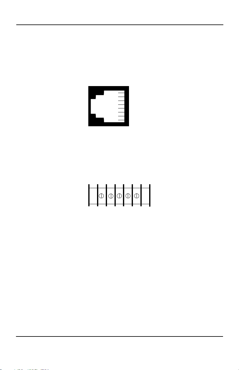
1. The RJ-45 jack on a ME475A-R2 Short Range Modem is pre-wired for a standard TELCO wiring environment. To be sure you have the right wiring, use the
table below as a guide.
RJ-45 Signal
1 ------------------ NC
2 ------------------ GND†
3 ------------------ RCV
4 ------------------ XMT
5 ------------------ XMT
6 ------------------ RCV
7 ------------------ GND
8 ------------------ NC
† Connection to ground is optional
2. Proper wiring of pairs between the two modems is as follows:
Page 14
724-746-5500 | blackbox.com
Page 15
Installation
1 - Blue
2 - Orange
3 - Black
4 - Red
5 - Green
6 - Yellow
7 - Brown
8 - Slate
RX+ RX- GND TX- TX+
Signal Pin# Color* Color Pin# Signal
XMT 4 Green --------- Green 4 XMT
XMT 5 Red --------- Red 5 XMT
3. AT&T standard modular color codes:
Two-Wire Cable Connection Via Terminal Blocks
If you are not going to use the modular jacks, follow the instructions below.
1. Locate the terminal block on the back of the unit. It should look like the following
diagram:
*Standard color codes—yours may be different
Note The “+” and “-” indicators are for reference only. The ME475A-R2 is not sensi-
tive to polarity.
2. Connect one wire of the pair to a Transmit lug (TX+ or TX-) on both the local and
remote ME475A-R2.
3. Connect the other wire of the pair to the other Transmit lug on both the local and
remote ME475A-R2.
4. If there is a shield around the telephone cable, it may be connected to GND on
the terminal block. We recommend connecting the shield at the computer end
only to avoid ground loops. A ground wire is not necessary for proper operation
of these units.
5. When you finish connecting the telephone line to units at both ends, it should
look like the following diagram:
724-746-5500 | blackbox.com
Page 15
Page 16

Black Box Short Range Modem
XMT XMT
XMT XMT
GND GND
To Shield (Optional)
}
One Pair
3.2 FOUR-WIRE INSTALLATION
When communicating over a two twisted pair circuit, the ME475A-R2 can operate full
or half duplex, point-to-point or multipoint. In two pair point-to-point applications, you
will need a pair of ME475A-R2s for each circuit—one at each end of the single pair
wire. In two pair multipoint applications you will need three or more ME475A-R2 units.
These can be connected using a star topology, although a daisy chain topology is usually used.
Four-Wire Cable Connection Via RJ-45
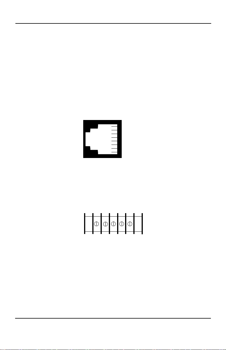
1. The RJ-45 jack on a ME475A-R2 Short Range Modem is pre-wired for a standard TELCO wiring environment. To be sure you have the right wiring, use the
table below as a guide.
RJ-45 Signal
1 ------------------ NC
2 ------------------ GND†
3 ------------------ RCV
4 ------------------ XMT
5 ------------------ XMT
6 ------------------ RCV
7 ------------------ GND
8 ------------------ NC
†Connection to ground is optional
2. Proper crossing of pairs between the two modems is as follows:
Page 16
724-746-5500 | blackbox.com
Page 17
Installation
1 - Blue
2 - Orange
3 - Black
4 - Red
5 - Green
6 - Yellow
7 - Brown
8 - Slate
RX+ RX- GND TX- TX+
Signal Pin# Color* Color Pin# Signal
GND† 2 Orange --------- Brown 7 GND
RCV 3 Black --------- Green 5 XMT
XMT 4 Red --------- Yellow 6 RCV
XMT 5 Green --------- Black 3 RCV
RCV 6 Yellow --------- Red 4 XMT
GND 7 Brown --------- Orange 2 GND
3. AT&T standard modular color codes:
Four-Wire Cable Connection Via Terminal Blocks
If you are not going to use the modular jacks then follow the instructions below.
*Standard color codes—yours may be different
†Connection to ground is optional
1. Locate the terminal block on the back of the unit. It should look like the following
diagram:
* The “+” and “-” indicators are for reference only.
The ME475A-R2 is not sensitive to polarity.
2. Connect one pair of wires in the telephone cable to the Transmit lugs (TX+ and
TX-) on the terminal block.
3. Connect the other pair of wires in the telephone cable to the Receive lugs (RX+
and RX-) on the terminal block.
4. If there is a shield around the telephone cable, it may be connected to "G" on the
terminal block. We recommend connecting the shield at the computer end only
724-746-5500 | blackbox.com
Page 17
Page 18

Black Box Short Range Modem
XMT RCV
XMT RCV
GG
RCV XMT
RCV XMT
To Shield (Optional)
}
One Pair
}
One Pair
to avoid ground loops. A ground wire is not necessary for proper operation of
these units.
5. When you finish connecting the telephone line to units at both ends, it should
look like the following diagram:
3.3 FOUR-WIRE, MULTIPOINT INSTALLATION
Multipoint operation involves the connection of several terminals to one host port. In
such an application, one local ME475A-R2 is used as a master unit, and it is con
nected to several remote ME475A-R2s that are acting as slaves. Up to 25 ME475A-R2
slaves may be connected to one host ME475A-R2 master SRM, provided that the
computing hardware and software support that many terminal drops.
In a multipoint environment the master ME475A-R2 transmits continually. Initiation of
two-way communication is carrier-controlled by each “slave” ME475A-R2 unit.
To facilitate multipoint communication, the master ME475A-R2 should have its carrier
control DIP switch set to “constantly ON” (S1-8=OFF). Each slave ME475A-R2 unit
should have its carrier control DIP switch set to “controlled by RTS” (S1-8=ON).
Figure 4 illustrates a typical ME475A-R2 multipoint application.
-
Page 18
724-746-5500 | blackbox.com
Page 19
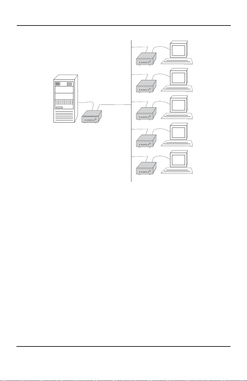
Figure 4. Typical multipoint set-up
Installation
Multipoint Twisted Pair Connection
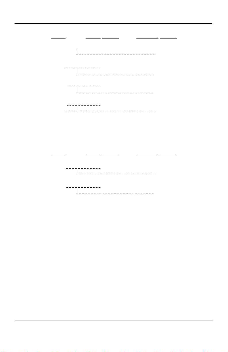
The ME475A-R2 supports multipoint applications using a star topology. Maximum distance between the units will vary based upon the number of drops, data rate, wire
gauge, etc. The diagrams below show how to wire the one-pair and two-pair cables
properly for a star topology. Note that the ground connection is not needed.
724-746-5500 | blackbox.com
Page 19
Page 20
Black Box Short Range Modem
HOST FIRST SLAVE SECOND SLAVE
XMT RCV
RCV
XMT RCV
RCV
RCV XMT
XMT
RCV XMT
XMT
HOST FIRST SLAVE SECOND SLAVE
XMT XMT
XMT
XMT XMT
XMT
3.4 RS-232 CONNECTION
Connect the synchronous or asynchronous output of your RS-232 device to the DB-25
interface on the rear panel of the ME475A-R2.
Note The ME475A-R2 is wired to connect to a DTE. If your RS-232 output device is
Once you have configured each ME475A-R2 unit properly and connected the twisted
pair and RS-232 cables (see Section 4.0), you are ready to operate the units. This sec
tion describes reading the LED status monitors, powering-up and using the built-in
V.52 and V.54 test modes.
DCE, Operation
Page 20
Figure 5. Twisted Pair Connection
724-746-5500 | blackbox.com
-
Page 21
Operation
4. OPERATION
4.1 LED STATUS MONITORS
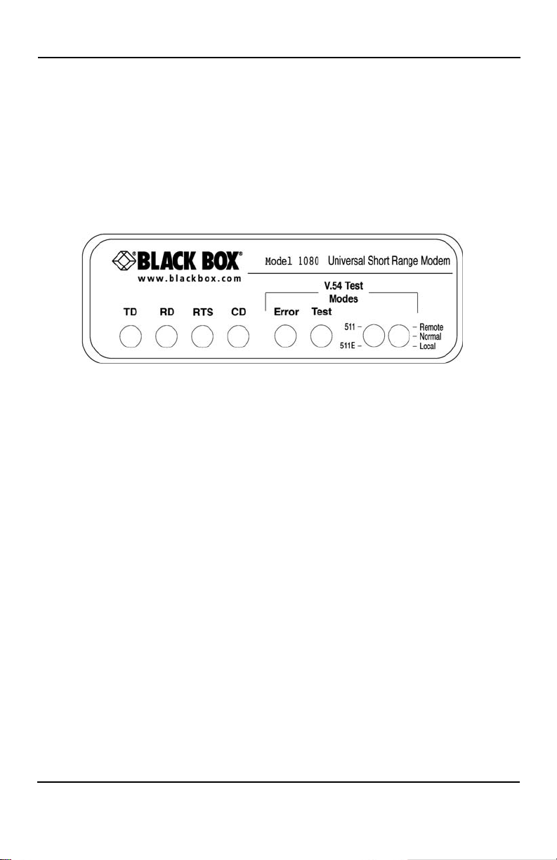
The ME475A-R2 features six front panel status LED that indicate the condition of the
modem and communication link.
Following Figure 6 is a description of each LED’s function.
The “TD” and “RD” Indicators
The “TD” and “RD” indicators blink red and green with data activity. Red indicates a
low RS-232 logic level, green indicates a high RS-232 logic level.
Figure 6 shows the front panel location of each LED.
Figure 6. Front view of ME475A-R2
Note RS-232 devices idle in a low state, so the LED will glow red if the connections
are correct and the RS-232 device is in an idle state.
The “RTS” and “CD” Indicators
The “RTS” and “CD” indicators are bi-color and will glow red for a “low” signal or green
for a “high” signal. RTS lights for an incoming signal on RS-232 pin 4. CD lights for an
incoming signal on the line side, and the resulting output signal on RS-232 pin 8.
The “Test” Indicator
The green “Test” LED indicates that V.52 or V.54 tests are running.
724-746-5500 | blackbox.com
Page 21
Page 22

Black Box Short Range Modem
The “Error” Indicators
The “Error” indicator LED has three functions:
1. When the ME475A-R2 unit is in test mode (green “Test” LED is lit), the error LED
glows red when bit errors occur.
2. When not in test mode (green “Test” LED is off), the error LED is used to indicate
an RTS streaming condition. (See Section 5.2) for information on the antistreaming circuitry.
3. The “Error” LED is also used to detect line quality as depected by the following:
A. The improper use of flat (non-twisted pair) cable to connect the modems.
B. One or more broken wires in the 4 wire twisted pair cable.
C. The use of low quality twisted pair cable to connect the modems.
D. Broken or corroded connector.
Note In detecting line quality the “Error” LED indicator is designed for 4 wire twisted
pair cable only, and may not function properly with two wire cable.
Setting Up The “Error” LED To Test Cable Quality
If there is any question as to the quality of your line we recommend the following test:
1. Disconnect both local and remote modems from their RS-232 interface. Make
sure “TD”, “RD” and “RTS” LEDs are lit red.
2. Set input impedance of both modems to 200 ohms. (S3-1 “On”, S3-2 “Off”).
3. For ME475A-R2, set data rate on both modems for 9.6 kbps.
4. On local modem set “Carrier Constantly On”. (S1-8 “Off”)
5. Set remote modem to RTS control (S1-8, “On”).
6. Place both front panel toggle switches to neutral position. (Test Led will not light)
7. Connect both modems to the 4 wire twisted pair cable.
Reading The Test
1. If line quality is good, “Error” LED on local modem will not light and “CD” LED will
be red. On remote modem “Error” LED will not light and “CD” LED will light
green.
Page 22
724-746-5500 | blackbox.com
Page 23

Operation
2. If flat cable is used or parts of the line are flat cable, “Error” LED on local modem
will light red and “CD” LED will light green. On remote modem “Error” LED will
not light and “CD” LED will light green.
3. If one wire from the 4 wire twisted pair is broken “Error” LED will light red and
“CD” LED will light green on at least one modem.
Note We cannot guarantee accurate detection if small pieces of flat cable are present
in the line beyond 1500ft of the local modem.
4.2 ANTI-STREAMING ERROR INDICATOR
When not in test mode (green “Test” LED is off), the front panel “Error” LED is used to
indicate a streaming error. When the ME475A-R2’s anti-streaming circuitry is enabled,
the RTS signal from the DTE is timer controlled. The timer begins to count when the DTE
raises RTS. If the time period that RTS remains high exceeds the preset time out period,
the anti-stream circuit will force RTS low. The “Error” LED will light red, indicating a
streaming condition (RTS continually on). This feature prevents a malfunctioning termi
nal from tying-up a computer port in a multi-drop or polling environment. When the DTE
drops RTS, the anti-streaming timer is automatically reset and the front panel “Error”
LED turns off. The time out period is DIP switch selectable for 12.5 or 50 seconds.
4.3 POWER-UP
Apply AC power to the ME475A-R2 by plugging the separate AC power adapter first
into the rear panel of the ME475A-R2, and then into an acceptable AC power outlet.
There is no power switch on the ME475A-R2; and the remote/normal/loopback switch
should be set to “normal”. When the local and remote ME475A-R2s are both powered
up, and passing data normally, the following LED conditions will exist:
-
• TD & RD = flashing red and green
• RTS & DCD = green
• TEST = off
4.4 V.54 TEST MODES
The ME475A-R2 offers two V.54 test modes to evaluate the condition of the modems
and the communication link. These tests can be activated physically from the front
panel, or via the RS-232 interface
Note V.54 test modes are available for point-to-point applications only.
724-746-5500 | blackbox.com
Page 23
Page 24

Black Box Short Range Modem
Local Analog Loopback (LAL)
The Local Analog Loopback (LAL) test checks the operation of the local ME475A-R2
unit, and is performed separately on each unit. Any data sent to the local ME475A-R2
in this test mode will be echoed (returned) back to the user device. For example, characters typed on the keyboard of a terminal will appear on the terminal screen. To perform a LAL test, follow these steps:
1. Activate LAL. This may be done in one of two ways: First, by moving the front
panel toggle switch DOWN to "Local". Second, by raising pin 18 on the RS-232
interface (Note: Make sure DIP switch S2-6 is OFF, and DIP switch S3-5 is ON).
Once LAL is activated, the ME475A-R2’s transmit output is connected to its own
receiver. The "test" LED should be lit.
2. Verify that the data terminal equipment is operating properly and can be used for
a test. If a fault is indicated, call a technician or replace the unit.
3. Perform a BER (bit error rate) test on each unit. If the BER test equipment indicates no faults, but the data terminal indicates a fault, follow the manufacturer's
checkout procedures for the data terminal. Also, check the RS-232 interface
cable between the terminal and the ME475A-R2.
Remote Digital Loopback (RDL)
The Remote Digital Loopback (RDL) test checks the performance of both the local and
remote ME475A-R2s, and the communication link between them. Any characters sent
to the remote ME475A-R2 in this test mode will be returned back to the originating
device. For example, characters typed on the keyboard of the local terminal will appear
on the local terminal screen after having been passed to the remote ME475A-R2 and
looped back. To perform an RDL test, follow these steps:
1. Activate RDL. This may be done in two ways: First, by moving the front panel
toggle switch UP to "Remote". Second, by raising pin 21 on the RS-232 interface.
Note Make sure DIP switch S3-6 is ON; and DIP switch S2-6 is OFF.
2. Perform a BER (bit error rate) test on the system.
3. If the BER test equipment indicates a fault, and the Local Analog Loopback test
was successful for both ME475A-R2 units, you may have a problem with the
twisted pair line between the modems. You should then test the twisted pair line
for proper connections and continuity.
Page 24
724-746-5500 | blackbox.com
Page 25

Operation
Using the V.52 BER Test Independently
The V.52 BER test can be used independently of the V.54 loopback tests. This requires
two operators: one to initiate and monitor the test at the local ME475A-R2, and one at
the remote ME475A-R2. To use the V.52 BER test by itself, both operators should
simultaneously follow these steps:
1. Locate the “511/511E” toggle switch on the front panel of the unit and move it UP.
This activates the V.52 BER test mode and transmits a “511” test pattern to the
other unit. If any errors are present, the receiving modem's red “ERROR” LED
will blink sporadically.
Note For this test to function, the “511” switch on both ME475A-R2 units must be on.
2. If the test indicates no errors are present, move the V.52 toggle switch DOWN,
activating the “511/E” test with periodic errors present. If the test is working prop
erly, the receiving modem’s red “ERROR” LED will blink regularly. A successful
“511/E” test will confirm that the link is in place, and that the ME475A-R2’s builtin “511” generator and detector are working properly.
4.5 POWER-DOWN
Turn off the ME475A-R2 by simply unplugging the AC or DC power source from the
wall. There is no power switch.
-
724-746-5500 | blackbox.com
Page 25
Page 26

Black Box Short Range Modem
A. SPECIFICATIONS
A.1 TRANSMISSION FORMAT
Synchronous or asynchronous, 2-wire/half duplex, or 4-wire/full or half duplex
A.2 INTERFACE
RS-232 (CCITT V.24) connection via DB-25 female; twisted pair connection via RJ-45
or terminal block
A.3 TRANSMISSION LINE
2 or 4-wire UTP, 19 - 24 AWG
A.4 DATA RATES
Synchronous or asynchronous at 1.2, 1.8, 2.4, 3.6, 4.8, 7.2, 9.6, 14.4, 19.2, 28.8, 38.4,
and 57.6 kbps—switch selectable
A.5 CLOCKING
Internal, external or receive recover
A.6 CONTROLS
Carrier constantly “ON” or “controlled by RTS”; RTS/CTS delay set to no delay, 7 or 53
ms
A.7 APPLICATIONS
Point-to-point or multi-point
A.8 INDICATORS
Bi-color LED indicators for TD, RD, RTS & DCD; single LED indicators for Test and
Error
A.9 RTS ANTI-STREAM TIMER
12.5 sec., 50 sec., or disabled (switch selectable); tolerance: +50%, -0%
Page 26
724-746-5500 | blackbox.com
Page 27

Specifications
A.10 DIAGNOSTICS
V.52 compliant bit error rate pattern (511/511E pattern) generator and detector with
error injection mode; V.54 compliant—Local Analog Loopback and Remote Digital
Loopback, activated by front panel switch or via RS-232 interface
A.11 TRANSFORMER ISOLATION
1500 V RMS
A.12 SURGE PROTECTION
Immune to IEC-801-5 Level 2, 1kV
A.13 TEMPERATURE
32–122°F (0–50°C)
A.14 HUMIDITY
0–95%, non-condensing
A.15 DIMENSIONS
6.2W x 4.2H x 1.5L in. (15.7W x 10.7H x 3.8L cm)
A.16 POWER INPUT (US)
12, 24, or 48 VDC
724-746-5500 | blackbox.com
Page 27
Page 28
Black Box Short Range Modem
B. CABLE RECOMMENDATIONS
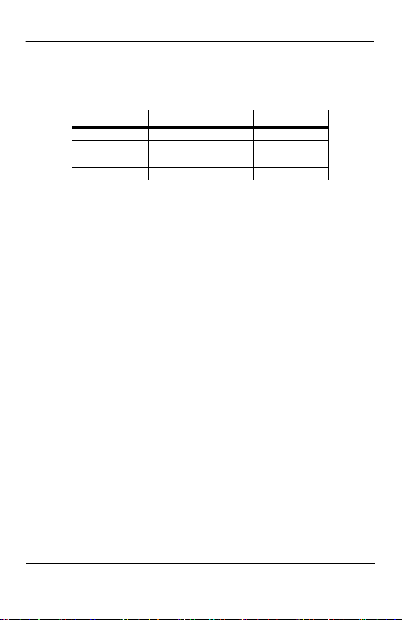
All Black Box Short Range Modems are tested to the distances published in our Catalogs and Specification Sheets on twisted-pair cable with the following characteristics:
Wire Gauge Capacitance Resistance
19 AWG(.9mm) 83nF/mi or 15.72 pF/ft. .0163 ohms/ft.
22 AWG(.6mm) 83nF/mi or 15.72 pF/ft. .0326+/ft.
24 AWG(.5mm) 83nF/mi or 15.72 pF/ft. .05165 ohms/ft.
26 AWG(.4mm) 83nF/mi or 15.72 pF/ft. .08235 ohms/ft.
We fully expect that the Short Range Modems will operate on lines with specifications
different from those tested, but to reduce the potential difficulties in the field, one
should ensure that the cable being used has similar or better characteristics (lower
capacitance or lower resistance).
Wire with capacitance of 20pF/ft. or less is suitable for all our Short Range Modems
however, distances may vary from those published in our catalog. Resistance will also
affect distance but not functionality. Wire should be 26 ohms (.4mm) or larger (smaller
AWG#).
Black Box products are designed to withstand normal environmental noise and conditions however, other environmental factors too numerous to discuss in this format may
affect proper operation of the SRM’s.
Selection of the proper SRM for an application is critical to maintaining Customer Satisfaction and should be taken seriously. Certain SRM configurations are better suited
for particular applications and environments than others.
Page 28
724-746-5500 | blackbox.com
Page 29
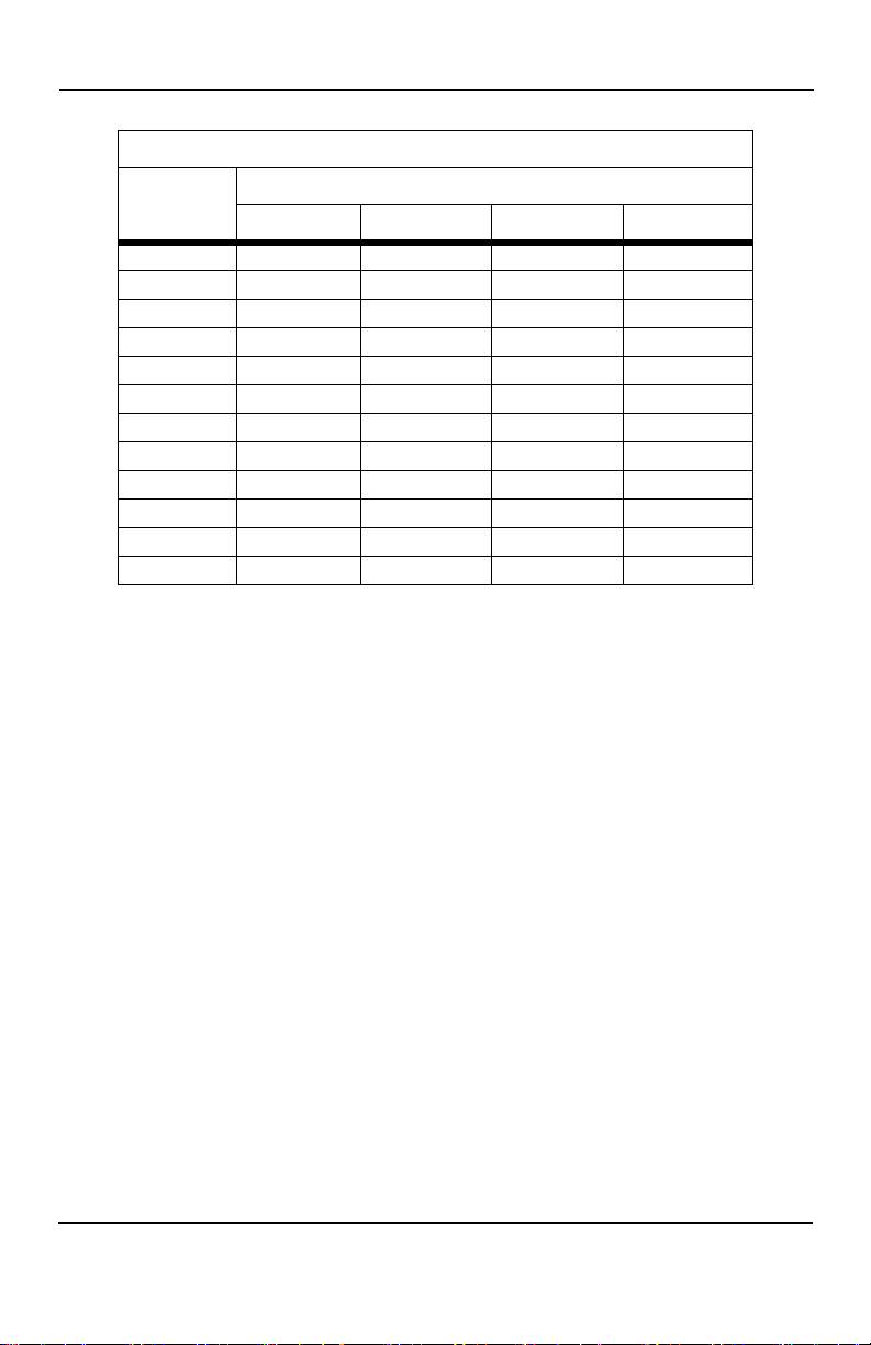
Cable Recommendations
ME475A-R2 Distance Table in Miles (km)
Data Rate
(bps)
57,600 12.0 (19.3) 7.0 (11.2) 5.3 (8.5) 4.0 (6.4)
38,400 13.0 (29.9) 7.5 (12.1) 6.2 (10.0) 4.2 (6.8)
28,800 14.0 (22.5) 8.0 (12.9) 6.6 (10.6) 4.6 (7.4)
19,200 16.0 (25.8) 8.5 (13.7) 7.0 (11.3) 5.1 (8.2)
14,400 17.0 27.4) 11.0 (17.7) 9.2 (14.9) 6.5 (10.50)
9,600 18.5 (29.8) 13.0 (20.9) 10.4 (16.7) 7.5 (12.1)
7,200 19.0 (30.6) 13.5 (21.7) 10.9 (17.5) 8.0 (12.9)
4,800 19.5 (31.4) 14.0 (22.5) 11.3 (18.2) 8.8 (14.2)
3,600 20.0(32.2) 14.5 (23.3) 11.5 (18.5) 8.8 (14.2)
2,400 20.5 (33.0) 15.0 (24.2) 11.6 (18.7) 9.0 (14.5)
1,800 20.5 (33.0) 15.0 (24.2) 11.5 (18.5) 8.9 (14.3)
1,200 20.0(32.2) 15.0 (24.2) 11.4 (18.4) 8.9 (14.3)
19 (.9) 22 (.6) 24 (.5) 26 (.4)
AWG Wire Gauge (mm)
724-746-5500 | blackbox.com
Page 29
Page 30
Black Box Short Range Modem
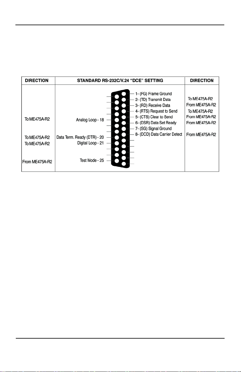
C. INTERFACE PIN ASSIGNMENT
RS-232 Female, D-Sub 25 Connector
(DCE Orientation)
Page 30
724-746-5500 | blackbox.com
Page 31
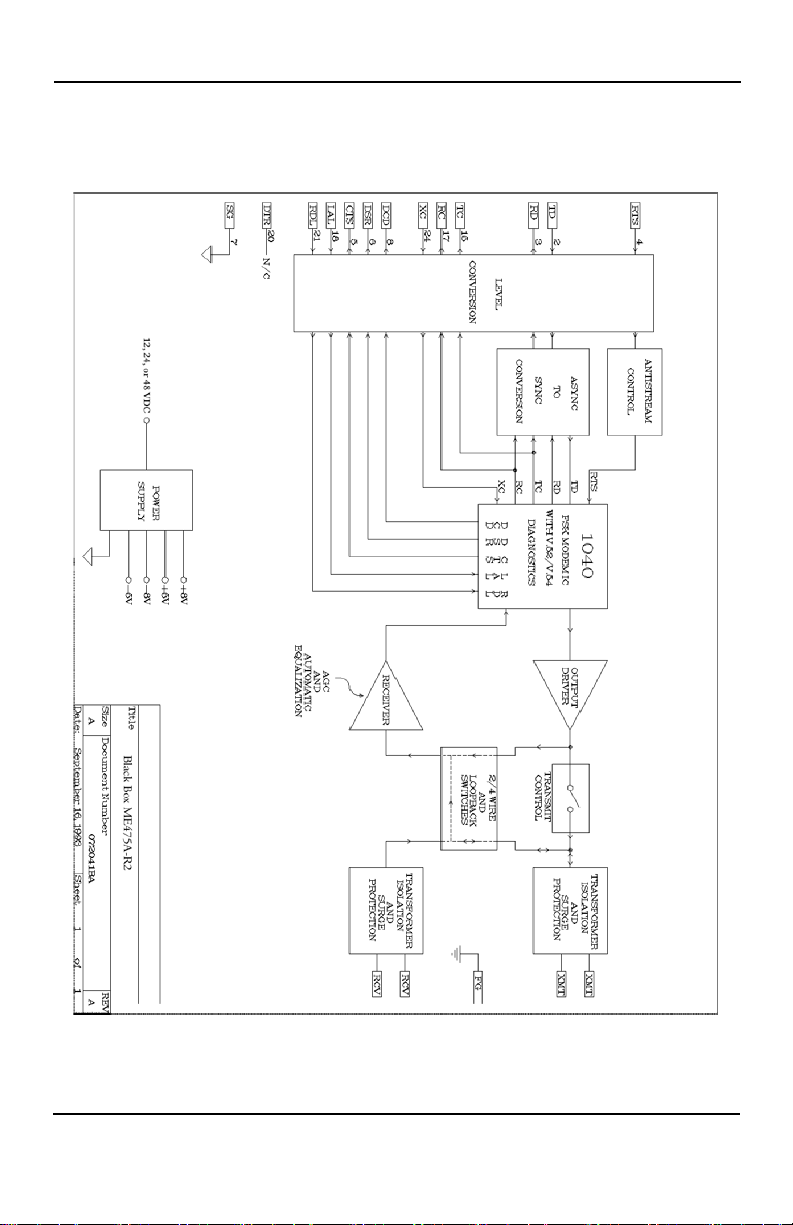
Black Box ME475A-R2 Block Diagram
D. BLACK BOX ME475A-R2 BLOCK DIAGRAM
724-746-5500 | blackbox.com
Page 31
Page 32

ME475A-R2 version 1
 Loading...