

Page 1
USER MANUAL
MCXG2 S ERI ES
MCX G2
ENCODERS
AND DECODERS
24/7 TECHNICAL SUPPORT AT 1.877.877.2269 OR VISIT BLACKBOX.CO M
Page 2

NEED HELP?
LEAV E TH E TEC H TO US
LIVE 24/7
TABLE OF CONTENTS
TECHNICAL
SUPPORT
1. 8 7 7. 8 7 7. 2 2 6 9
SAFETY PRECAUTIONS .................................................................................................................................................................................. 3
1.1 INTRODUCTION .......................................................................................................................................................................................... 4
1.2 APPLICATIONS ........................................................................................................................................................................................... 4
1.3 PACKAGE CONTENTS ............................................................................................................................................................................... 4
1.4 SYSTEM REQUIREMENTS ........................................................................................................................................................................5
1.5 FEAT U RE S ................................................................................................................................................................................................... 6
1.6 OPERATION CONTROLS AND FUNCTIONS ........................................................................................................................................... 7
1.6.1FRONT PANEL...............................................................................................................................................................................................................................7
1.6.2 REAR PANEL ................................................................................................................................................................................................................................ 8
1.6.3 IR CABLE PINOUTS ................................................................................................................................................................................................................. 10
1.6.4 RS-232 PINOUT AND DEFAULTS .......................................................................................................................................................................................10
1.6.5 OSD MENU ..................................................................................................................................................................................................................................11
1.6.6 Basic AV Extension ................................................................................................................................................................................................19
1.6.7 Advanced AV Extension ........................................................................................................................................................................................21
1.7 CONNECTION DIAGRAMS ........................................................................................................................................................ 26
1.8 SPECIFICATIONS ....................................................................................................................................................................... 28
2.1 INTRODUCTION ......................................................................................................................................................................... 34
2.2 APPLICATIONS .......................................................................................................................................................................... 34
2.3 PACKAGE CONTENTS ............................................................................................................................................................... 34
2.4 SYSTEM REQUIREMENTS ........................................................................................................................................................ 35
2.5 FEATURES .................................................................................................................................................................................. 36
2.6 OPERATION CONTROLS AND FUNCTIONS ............................................................................................................................ 37
2.6.1Front Panel ................................................................................................................................................................................................................37
2.6.2 Rear Panel ................................................................................................................................................................................................................38
2.6.3 IR Cable Pinouts .....................................................................................................................................................................................................40
2.6.4 RS-232 Pinout and Defaults .................................................................................................................................................................................40
2.6.5 OSD Menu ................................................................................................................................................................................................................41
2.6.6 Basic AV Extension ................................................................................................................................................................................................50
2.6.7 Advanced AV Extension ........................................................................................................................................................................................52
2.7 CONNECTION DIAGRAMS ........................................................................................................................................................ 57
2.8. SPECIFICATIONS ..................................................................................................................................................................... 59
A.1 ACRONYMS ............................................................................................................................................................................... 65
B.1 FCC STATEMENT ....................................................................................................................................................................... 67
B.2 CE S TATEMENT ......................................................................................................................................................................... 67
B.3 ROHS .......................................................................................................................................................................................... 67
B.4 NOM STATEMENT ..................................................................................................................................................................... 68
C.1 DISCLAIMER .............................................................................................................................................................................. 69
C.2 TRADEMARKS USED IN THIS MANUAL ................................................................................................................................. 69
2
1. 87 7.8 7 7. 2 26 9 BLACKBOX.COM
Page 3

NEED HELP?
LEAV E TH E TEC H TO US
LIVE 24/7
SAFETY
TECHNICAL
SUPPORT
1. 8 7 7. 8 7 7. 2 2 6 9
SAFETY PRECAUTIONS
Please read all instructions before attempting to unpack, install or operate this equipment and before connecting the power supply.
Please keep the following in mind as you unpack and install this equipment:
Always follow basic safety precautions to reduce the risk of fire, electrical shock and injury to persons.
To prevent fire or shock hazard, do not expose the unit to rain, moisture or install this product near water.
Never spill liquid of any kind on or into this product.
Never push an object of any kind into this product through any openings or empty slots in the unit, as you may damage parts inside the
unit.
Do not attach the power supply cabling to building surfaces.
Use only the supplied power supply unit (PSU). Do not use the PSU if it is damaged.
Do not allow anything to rest on the power cabling or allow any weight to be placed upon it or any person walk on it.
To protect the unit from overheating, do not block any vents or openings in the unit housing that provide ventilation and allow for sufficient
space for air to circulate around the unit.
Please completely disconnect the power when the unit is not in use to avoid wasting electricity.
1. 87 7.8 7 7. 2 26 9 BLACKBOX.COM
3
Page 4

NEED HELP?
LEAV E TH E TEC H TO US
LIVE 24/7
CHAPTER 1: ENCODERS
1.1 INTRODUCTION
This Encoder is designed for high-quality, IP routable, AV extension with virtually zero latency. The unit is capable of transmitting AV
and other data for long extension, enhancing the flexibility of any installation. By using a sophisticated ultra-light compression scheme
(lossless for most content) it is a great solution for extending 4K audio/video streams (HDMI or DisplayPort) and data. Advanced HDMI
content, such as HDR (High Dynamic Range), 10-bit color and multi-channel HD Bitstream audio, can be transmitted in pass-through
mode.
For the copper encoder, the use of high-quality, 10-Gbps Ethernet ports and Cat.6A or better cable allows for point-to-point transmission
of the video signal up to 100m.
For the fiber encoder, the use of interchangeable, field replaceable, SFP+ modules allows for transmission distances of up to 30km.
(Maximum transmission distance depends on the SFP+ modules used.)
Multiple control and data signals may also be transmitted along with the audio and video, including IR, RS-232, and Ethernet.
When combined with the optional MCX Gen2 Controller,or control software, the functionality of the Transceiver expands exponentially.
Multiple encoders/decoders may be combined with one or more 10-Gigabit fiber Ethernet switches. The units can be used together to
form a distributed video matrix, a multi-viewer system, or a video wall system. This AV network capability provides flexibility in large event
installations.
The integrated USB hub of each decoder can be congured to be in USB Host or Device Mode. It can function as a simple point-topoint KVM extension, freely routed between any two endpoints, or it can be congured into a special “Simultaneous” mode, allowing
up to 7 Host Mode units to extend their USB ports to a single Device Mode unit. This type of USB KVM routing exibility enables a
wide range of multi-user, control room, or on-demand installation scenarios.
The built-in EDID and HDCP management functionality enables the unit to fit into every video distribution situation. Basic configuration
of the unit can be achieved via front panel buttons with an OSD (On-Screen Display). Advanced control requires the optional MCX Gen2
controller, or control software, and a LAN connection.
TECHNICAL
SUPPORT
1. 8 7 7. 8 7 7. 2 2 6 9
1.2 APPLICATIONS
Video, Audio, LAN, IR, and USB over copper cable or fiber extension
Long distance data and video transmission immune to RF interference
Point-to-point secure video conferencing
Hotel or convention center display
Multi-monitor broadcast
Distributed video matrix system
Distributed video wall system
Remote KVM system control
1.3 PACKAGE CONTENTS
(1) UHD+ copper or fiber transmitter
(1) 12V/3A DC power adapter
(1) Power cord
(1) IR emitter
4
1. 87 7.8 7 7. 2 26 9 BLACKBOX.COM
Page 5

NEED HELP?
LEAV E TH E TEC H TO US
LIVE 24/7
CHAPTER 1: ENCODERS
TECHNICAL
SUPPORT
1. 8 7 7. 8 7 7. 2 2 6 9
1.4 SYSTEM REQUIREMENTS
HDMI or DisplayPort source equipment, such as a media player, video game console, PC, or set-top box
HDMI receiving equipment, such as an HDTV, monitor, or audio amplifier
Analog audio receiving equipment, such as headphones, an audio amplifier, or powered speakers
A 10-Gbps Ethernet network switch with jumbo frame and IGMP snooping support is required for distributed video systems. (Optional,
required for multi-encoder/decoder copper systems)
A 10-Gbps fiber Ethernet network switch with jumbo frame and IGMP snooping support is required for distributed video systems.
(Optional, required for multi-encoder/decoder fiber systems)
IEEE 802.3ae compatible SFP+ fiber module supporting a dual-optical fiber connection style, such as LC, or a pre-terminated crossover
dual-optical fiber cable (required for fiber encoder)
Note: Single-mode and multi-mode support is dependent on the SFP+ modules used
MCX Gen2 Controller or control software to configure distributed matrix, video wall or multi-view systems (Optional)
1. 87 7.8 7 7. 2 26 9 BLACKBOX.COM
5
Page 6

NEED HELP?
LEAV E TH E TEC H TO US
LIVE 24/7
CHAPTER 1: ENCODERS
1.5 FEATURES
HDMI 2.0 and DVI 1.0 compatible
HDCP 2.2 and HDCP 1.x compliant
(1) HDMI and (1) Type C input, (1) HDMI output, (1) analog stereo
IP switchable with minimum latency (requires optional MCX Gen2 controller or control software)
Ultra-light compression, lossless for most content
Extension up to 100m in point-to-point mode (with CAT.6A cable for copper encoder)
Extension up to 30km (maximum distance depends on the SFP+ module and type of fiber used for fiber encoder)
Supports independent breakaway A/V matrix switching with minimum latency, video wall generation, and multi-view compositing
(requires optional MCX Gen2 controller/control software)
Supports pass-through of 10/12-bit HDR sources (point-to-point and bypass modes only)
Supports pass-through of audio formats including LPCM (up to eight channels), Bitstream and HD Bitstream from HDMI or DP sources
AV, IR, RS-232, USB 2.0, and ethernet extension
Unit can be powered directly by PoE when connected to a 10 Gigabit Ethernet (10GbE) switch that provides PoE (802.3at) (for copper
encoder)
Signal transmission interfaces with 10-Gigabit Ethernet switches via XFI (IEEE 802.3ae) compatible SFP+ fiber modules (for fiber encoder)
Basic configuration via front panel buttons with an OSD
Supports the use of an external control center (MCX Gen2 Controller) or control software to provide expanded functionality (Contact Black
Box for more information.)
TECHNICAL
SUPPORT
1. 8 7 7. 8 7 7. 2 2 6 9
6
1. 87 7.8 7 7. 2 26 9 BLACKBOX.COM
Page 7
CHAPTER 1: ENCODERS
1.6 OPERATION CONTROLS AND FUNCTIONS
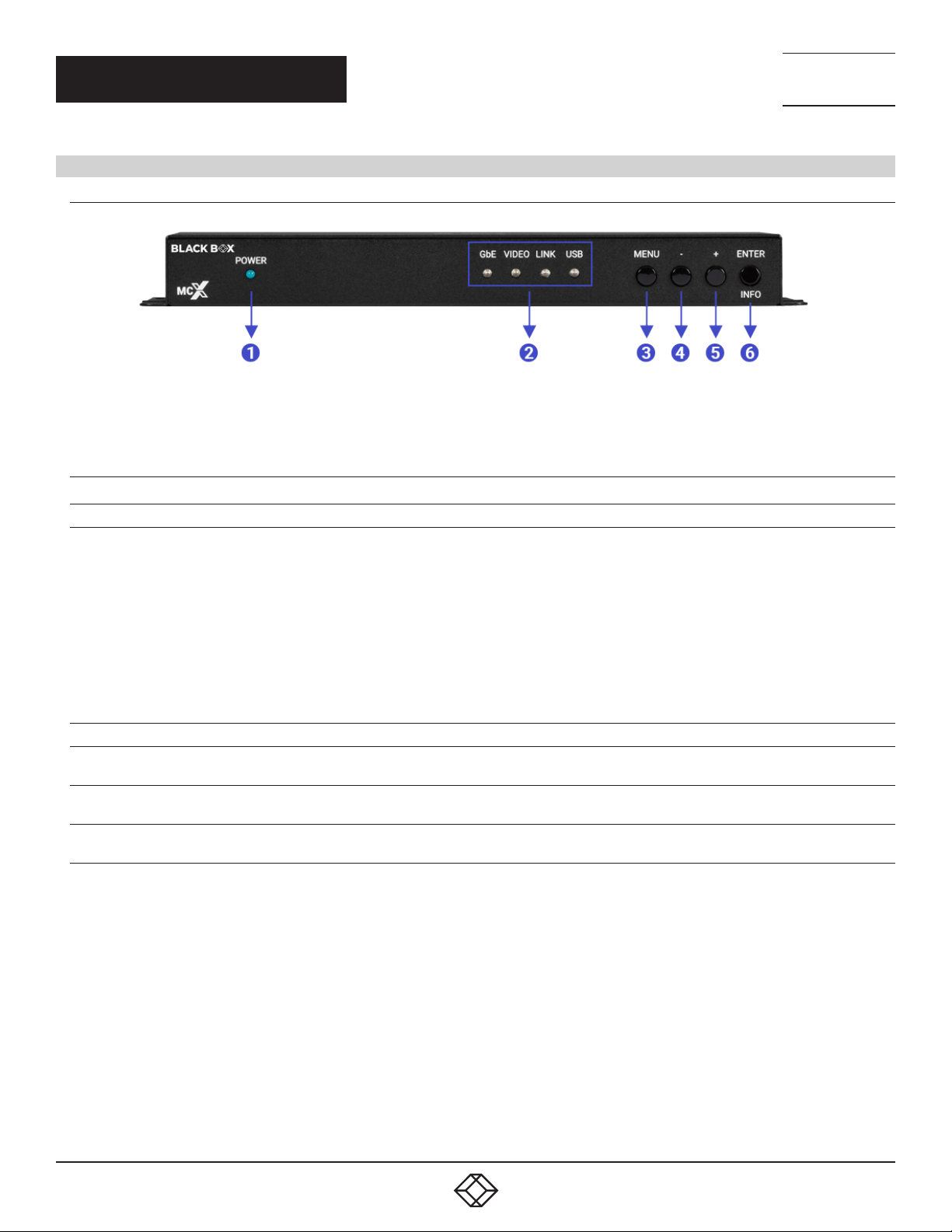
1.6.1FRONT PANEL
TABLE 1-1. FRONT-PANEL COMPONENTS
FIGURE 1-1: FRONT PANEL
NEED HELP?
LEAV E TH E TEC H TO US
LIVE 24/7
TECHNICAL
SUPPORT
1. 8 7 7. 8 7 7. 2 2 6 9
NUMBER IN FIGURE 1-1 COMPONENT DESCRIPTION
1 (1) Power LED indicator Lights ON or OFF for Power
GbE LED: This LED will illuminate and blink to indicate a live and active connection
on the local gigabit Ethernet port.
VIDEO LED: This LED will illuminate Green when a video signal is live on the optical
fiber streaming port or illuminate Amber when streaming a detected input stream.
When no video is active, the LED will remain off, even if the streaming connection is
2 (1) Status LED block
3 (1) Menu button Press to enter the OSD menu or to back out from menu items.
4 (1) Menu button: - Minus button
5 (1) Menu button: + button
6 (1) Enter/Info button
valid.
LINK LED: These LEDs will illuminate and blink to indicate data transmission and
reception activity across the optical fiber streaming connection.
USB LED: This LED will illuminate when the unit’s USB ports have successfully
paired with the USB ports on another unit. This LED will blink if the unit’s USB ports
are not currently paired and are in stand-by mode.
Press to move up or adjust selections within OSD menus. When not in a menu,
press to manually switch between encoder source inputs.
Press to move up or adjust selections within OSD menus. When not in a menu,
press to manually switch between decoder source inputs.
When inside an OSD menu, press to confirm a selection or to go deeper into a menu
item. When not in a menu, press to activate the Information OSD.
1. 87 7.8 7 7. 2 26 9 BLACKBOX.COM
7
Page 8
CHAPTER 1: ENCODERS
1.6.2 R E AR PANEL
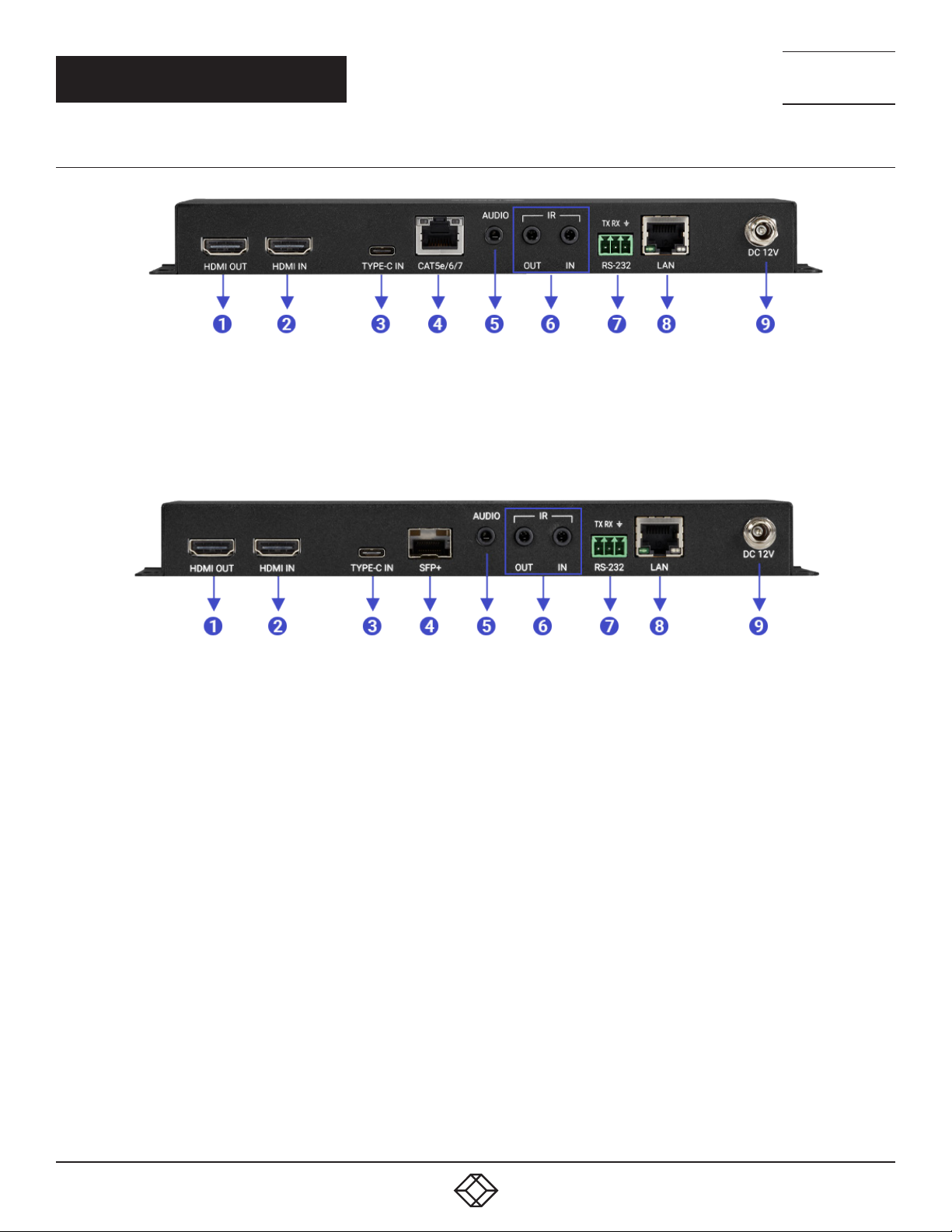
FIGURE 1-2: REAR PANEL (COPPER)
NEED HELP?
LEAV E TH E TEC H TO US
LIVE 24/7
TECHNICAL
SUPPORT
1. 8 7 7. 8 7 7. 2 2 6 9
FIGURE 1-3: REAR PANEL (FIBER)
8
1. 87 7.8 7 7. 2 26 9 BLACKBOX.COM
Page 9

CHAPTER 1: ENCODERS
TABLE 1-2. REAR-PANEL COMPONENTS
NEED HELP?
LEAV E TH E TEC H TO US
LIVE 24/7
TECHNICAL
SUPPORT
1. 8 7 7. 8 7 7. 2 2 6 9
NUMBER IN FIGURE
1-2/1-3
1 (1) HDMI Out Port Connect to an HDMI TV, monitor, or amplifier for digital video and audio output.
2 (1) HDMI In Port
3 (1) Type C In Port Connect to Type C or DisplayPort-to-Type C source equipment, such as a PC or laptop.
4
COMPONENT DESCRIPTION
Connect to HDMI source equipment, such as a media player, game console, or set-top
box.
Connect directly to a compatible encoder/decoder for point-to-point extension, or to a
10 Gigabit Ethernet switch for distributed matrixing (requires MCX Gen2 Controller or
(1) Cat5E/6/7 port
OR
(1) SFP+ port
control software) with a single Cat.5e/6/7 cable for extension of all data signals (for
copper encoder).
NOTE: If the connected network switch supports the IEEE 802.3at-2009 PoE
(Power over Ethernet) standard, this unit can optionally be powered directly via this
Ethernet port.
Insert a standard SFP+ module and connect the appropriate optical cable to allow
data transmission to a compatible transceiver or to a 10-gigabit optical fiber network
switch (for fiber encoder).
NOTE: The SFP+ module must support a dual-optical fiber connection style, such
as LC, or be pre-terminated dual-optical fiber cables. Single-mode and multi-mode
support is dependent on the SFP+ modules used.
5 (1) Audio port
6 (2) IR ports
7 (1) RS-232 Terminal Block
8 LAN Port
9 DC 12V Port
As O UT: Connect to powered speakers or an amplifier for stereo analog audio output.
As IN: Connect to the stereo analog output of a device, such as a CD player or PC.
NOTE: When the encoder and decoder are connected directly in a point-to-point
configuration, audio is routed directly to the opposite end’s Ports. Free routing can
only be configured by use of the optional MCX Gen2 Master Controller or control
software.
OUT Port: Connect to an IR Blaster to broadcast IR signals from a connected
transceiver to devices within direct line-of sight of the IR Blaster.
IN Port: Connect to an IR Extender to receive IR control signals and extend them to
devices connected to a connected transceiver. Ensure that the remote being used is
within direct line-of-sight of the IR Extender.
NOTE: Currently, only 38KHz IR signal extension is supported.
Connect directly to a PC, laptop or serial controllable device with a 3-pin adapter cable
to extend the RS-232 signal between transceivers.
Connect to an Ethernet supporting device or to your local network as appropriate to
extend the network between transceivers.
Plug the 12V DC power adapter into this port and connect it to an AC wall outlet for
power.
1. 87 7.8 7 7. 2 26 9 BLACKBOX.COM
9
Page 10
CHAPTER 1: ENCODERS
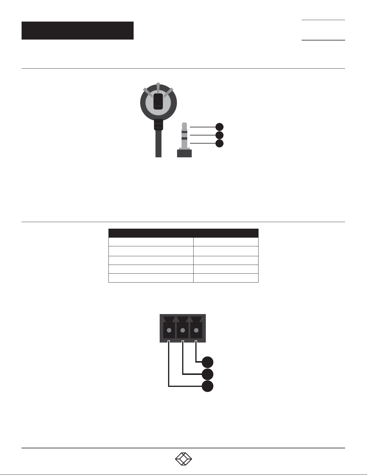
1.6.3 IR CABLE PINOUTS
IR Extender Cable
1
Infrared
2
Power
3
Ground
FIGURE 1-4: IR EXTENDER CABLE PINOUTS
NEED HELP?
LEAV E TH E TEC H TO US
LIVE 24/7
TECHNICAL
SUPPORT
1. 8 7 7. 8 7 7. 2 2 6 9
1.6.4 RS-232 PINOUT AND DEFAULTS
BA U D RATE
DATA BIT S 8
PARITY BITS NONE
STOP BITS 1
FLOW CONTROL NONE
3-PIN TERMINAL BLOCK
57600
FIGURE 1-5: SERIAL PORT DEFAULT SETTINGS
GND
1
RxD
2
TxD
3
FIGURE 1-6: 3-PIN TERMINAL BLOCK
NOTE: The default Serial Port baud rate can only be changed by use of the optional MCX Gen2 Controller or control software.
10
1. 87 7.8 7 7. 2 26 9 BLACKBOX.COM
Page 11

NEED HELP?
LEAV E TH E TEC H TO US
LIVE 24/7
CHAPTER 1: ENCODERS
TECHNICAL
SUPPORT
1. 8 7 7. 8 7 7. 2 2 6 9
1.6.5 OSD MENU All functions of this unit can be controlled by using the OSD (On Screen Display) which is activated by pressing the [MENU] button on
the front of the unit. Use the [+] (PLUS), [−] (MINUS), and [ENTER] buttons to navigate the OSD menu. Press the [MENU] button to back
out from any menu item and then press it again to close the menu.
MAIN MENU
OSD
EDID
HDCP
DEVICE SETTING
INFORMATION
USB INFORMATION
FACTORY SETTING
FIGURE 1-7: MAIN MENU
The individual functions of the OSD will be introduced in the following section. Items marked in BOLD are the factory default settings.
1. 87 7.8 7 7. 2 26 9 BLACKBOX.COM
11
Page 12

CHAPTER 1: ENCODERS
OSD
2ND LEVEL 3RD LEVEL
DISPLAY INFORMATION
INFORMATION TIMEOUT
ON
OFF
OFF
10~40 S E C [10 SEC]
MENU TIMEOUT OFF
10~40 S E C [10 SEC]
MENU H POSITION 0~100 [10]
MENU V POSITION
FIGURE 1-8: OSD MENU
0~100 [10]
TABLE 1-3. OSD
NEED HELP?
LEAV E TH E TEC H TO US
LIVE 24/7
TECHNICAL
SUPPORT
1. 8 7 7. 8 7 7. 2 2 6 9
SECOND LEVEL IN FIGURE 1-8 SELECTION DESCRIPTION
Display Information On/Off Enable or disable the Information OSD.
Information Timeout Multiple Set the display timeout for the Information OSD.
Menu Timeout Multiple Set the display timeout for the OSD Menu.
Menu H position Multiple Set the horizontal position of the OSD Menu.
Menu V Position Multiple Set the horizontal position of the OSD Menu.
12
1. 87 7.8 7 7. 2 26 9 BLACKBOX.COM
Page 13

CHAPTER 1: ENCODERS
EDID
2ND LEVEL 3RD LEVEL
HDMI EDID
TYPE-C EDID INTERNAL 1 (FHD 2CH)
VOIP EDID
INTERNAL 1 (FHD 2CH)
INTERNAL 2 (FHD MCH)
INTERNAL 3 (UHD 2CH)
INTERNAL 4 (UHD MCH)
INTERNAL 5 (UHD+ 2CH)
INTERNAL 6 (UHD+ MCH)
EXTERNAL A [HDMI OUTPUT]
EXTERNAL B [VOIP OUTPUT]
USER 1
USER 2
INTERNAL 2 (FHD MCH)
INTERNAL 3 (UHD 2CH)
INTERNAL 4 (UHD MCH)
INTERNAL 5 (UHD+ 2CH)
INTERNAL 6 (UHD+ MCH)
EXTERNAL A [HDMI OUT]
EXTERNAL B [VOIP OUT]
USER 1
USER 2
EXTERNAL A
FIGURE 1-9: EDID MENU
NEED HELP?
LEAV E TH E TEC H TO US
LIVE 24/7
TECHNICAL
SUPPORT
1. 8 7 7. 8 7 7. 2 2 6 9
TABLE 1-4. EDID
SECOND LEVEL IN FIGURE 1-9 SELECTION DESCRIPTION
HDMI EDID Multiple Select the EDID to send to the unit’s HDMI input.
Type C EDID Multiple Select the EDID to send to the unit’s DisplayPort input.
VOIP EDIC Multiple
1. 87 7.8 7 7. 2 26 9 BLACKBOX.COM
The EDID provided to Video over IP connections is always set to use the
EDID from the unit’s local HDMI output.
13
Page 14

CHAPTER 1: ENCODERS
This unit provides the following six default EDIDs:
UNIT’S DEFAULT EDIDS
FHD 2CH
FHD MCH
UHD 2CH
UHD MCH
UHD+ 2CH
UHD+ MCH
1920×1080P@60HZ (4.95GBPS), 8-BIT COLOR,
LPCM 2.0
1920×1080P@60HZ (4.95GBPS), 8-BIT COLOR,
LPCM 7.1 & BITSTREAM
3840×2160P@30HZ (10.2GBPS), 12-BIT DEEP COLOR,
LPCM 2.0
3840×2160P@30HZ (10.2GBPS), 12-BIT DEEP COLOR,
LPCM 7.1 & BITSTREAM
3840×2160P@60HZ (18GBPS), 12-BIT DEEP COLOR,
LPCM 2.0
3840×2160P@60HZ (18GBPS), 12-BIT DEEP COLOR,
LPCM 7.1 & BITSTREAM
FIGURE 1-10: DEFAULT EDIDS
NEED HELP?
LEAV E TH E TEC H TO US
LIVE 24/7
TECHNICAL
SUPPORT
1. 8 7 7. 8 7 7. 2 2 6 9
NOTE: In some rare cases it is possible for custom or external EDIDs to cause compatibility issues with certain sources. If this
happens, it is recommended to switch to one of the six default EDIDs for maximum compatibility.
14
1. 87 7.8 7 7. 2 26 9 BLACKBOX.COM
Page 15

CHAPTER 1: ENCODERS
HDCP
2ND LEVEL 3RD LEVEL
HDMI HDCP
DISABLE
FOLLOW OUT
FOLLOW IN
FOLLOW API
TYPE C HDCP
DISABLE
FOLLOW OUT
FOLLOW IN
FOLLOW API
VOIP HDCP
FIGURE 1-11: HDCP MENU
FOLLOW IN
TABLE 1-5. HDCP
NEED HELP?
LEAV E TH E TEC H TO US
LIVE 24/7
TECHNICAL
SUPPORT
1. 8 7 7. 8 7 7. 2 2 6 9
SECOND LEVEL IN FIGURE 1-11 SELECTION DESCRIPTION
Selects the HDCP logic to use with the HDMI input.
Follow In: The input supports up to the HDCP version required by
the connected source.
Follow Out: The input supports up to the HDCP version supported
by the connected display.
HDMI HDCP Multiple
Type C HDCP Multiple
Disable: HDCP support is completely disabled.
Follow API: Uses the HDCP setting dened by the MCX Gen2
Controller or control software.
NOTE: In a point-to-point conguration, “Follow API” will behave
the same as “Follow Out”, if the API hasn’t been manually
redened.
Selects the HDCP logic to use with the DisplayPort input.
Follow In: The input supports up to the HDCP version required by
the connected source.
Follow Out: The input supports up to the HDCP version supported
by the connected display.
Disable: HDCP support is completely disabled.
Follow API: Uses the HDCP setting dened by the MCX Gen2
Controller or control software.
NOTE: In a point-to-point conguration, “Follow API” will behave
the same as “Follow Out”, if the API hasn’t been manually
redened.
VOIP EDID Standard The Video-over-IP HDCP behavior is always “Follow In.”
1. 87 7.8 7 7. 2 26 9 BLACKBOX.COM
15
Page 16

CHAPTER 1: ENCODERS
DEVICE SETTING
2ND LEVEL 3RD LEVEL
STAT U S TRANSCEIVER
USB CONTROL
MODE
USB VIRTUAL HUB OFF
HDMI OUT SOURCE
VOIP OUT SOURCE INPUT 1 (HDMI)
HDMI OUT AUTO
MODE
VOIP OUT AUTO
MODE
HOST
DEVICE
ON
INPUT 1 (HDMI)
INPUT 2 (DP)
INPUT 3 (VOIP)
INPUT 2 (DP)
INPUT 3 (VOIP)
OFF
AUTO SWITCH
OFF
AUTO SWITCH
FIGURE 1-12: DEVICE SETTING MENU
NEED HELP?
LEAV E TH E TEC H TO US
LIVE 24/7
TECHNICAL
SUPPORT
1. 8 7 7. 8 7 7. 2 2 6 9
TABLE 1-6. DEVICE SETTINGS
SECOND LEVEL IN FIGURE 1-12 SELECTION DESCRIPTION
Displays the unit’s current operational mode.
STAT U S Transceiver
USB Control Mode Multiple
USB Virtual hub Off/On
HDMI Out Source Multiple Select the input source to display on the HDMI output.
VOIP Out Source Multiple Select the input source to transmit as an AV over IP stream.
HDMI Out Auto Mode Off/Auto Switch
VOIP Out Auto Mode Off/Auto Switch
NOTE: Due to this unit’s support of bi-directional transmission, the status
will always be set to “Transceiver.”
Enable or disable the USB 2.0 (Mini-B) port for connection to USB host devices,
such as a PC or laptop. Selecting [Device] enables the USB 2.0 (Mini-B) port.
Selecting [Host] disables the USB 2.0 (Mini-B) port.
NOTE: In a point-to-point extension conguration, only one of the two
transceivers should be set as a USB Device to avoid conicts.
Enables or disables the “simultaneous connection” USB mode which allows
the PC/Laptop connected to this unit to be paired with the USB devices on up
to seven “Host” mode transceivers.
NOTE: Only available when USB Control Mode is set to “Device”. USB routing
can only be congured by use of the optional MCX Gen2 Controller or
control software and is not valid in point-to-point congurations.
Enable or disable the HDMI output’s automatic source selection mode. When
enabled, the unit will automatically switch the input routed to the local HDMI
output whenever a new source is detected or if the current source is lost.
Enable or disable the AVoIP streaming output’s automatic source selection
mode. When enabled, the unit will switch the input routed to the AVoIP output
whenever a new source is detected or if the current source is lost.
16
1. 87 7.8 7 7. 2 26 9 BLACKBOX.COM
Page 17

CHAPTER 1: ENCODERS
INFORMATION
2ND LEVEL 3RD LEVEL
RESOLUTION
STAT U S
FW VERSION [CURRENT FIRMWARE VERSION]
IP
MAC
SN
FIGURE 1-13: INFORMATION MENU
SECOND LEVEL IN FIGURE 1-13 SELECTION DESCRIPTION
Resolution Default Displays the unit’s detected source resolution
Status Default Displays the unit’s transceiver mode
FW Version Default Displays the unit’s rmware version
IP Default Displays the unit’s IP address
MAC Default Displays the unit’s MAC address
SN Default Displays the unit’s serial number
[CURRENT SOURCE RESOLUTION]
[CURRENT TRANSCEIVER MODE]
[CURRENT IP ADDRESS]
[UNIT’S MAC ADDRESS]
[UNIT’S SERIAL NUMBER]
TABLE 1-7. INFORMATION
NEED HELP?
LEAV E TH E TEC H TO US
LIVE 24/7
TECHNICAL
SUPPORT
1. 8 7 7. 8 7 7. 2 2 6 9
1. 87 7.8 7 7. 2 26 9 BLACKBOX.COM
17
Page 18

CHAPTER 1: ENCODERS
USB INFORMATION
2ND LEVEL 3RD LEVEL
IP MODE [UNIT’S USB IP MODE]
IP [UNIT’S USB IP ADDRESS]
MAC [UNIT’S USB MAC ADDRESS]
PAIR MAC 1
PAIR MAC 2
PAIR MAC 3
PAIR MAC 4
PAIR MAC 5
PAIR MAC 6
PAIR MAC 7
[USB MAC ADDRESSES OF
CONNECTED USB SOURCES]
FIGURE 1-14: USB INFORMATION MENU
NEED HELP?
LEAV E TH E TEC H TO US
LIVE 24/7
TECHNICAL
SUPPORT
1. 8 7 7. 8 7 7. 2 2 6 9
TABLE 1-8. USB INFORMATION
SECOND LEVEL IN FIGURE 1-14 SELECTION DESCRIPTION
IP Mode Default Displays the unit’s USB IP mode
IP Default Displays the unit’s USB IP address
MAC Default Displays the unit’s USB MAC address
PAIR MAC 1-7 Default Displays the unit’s USB addresses of connected USB sources
FACTORY SETTING
2ND LEVEL 3RD LEVEL
ARE YOU SURE? NO
YES
FIGURE 1-15: FACTORY SETTING MENU
TABLE 1-9. FACTORY INFORMATION
SECOND LEVEL IN FIGURE 1-15 SELECTION DESCRIPTION
Selecting [Yes] will reset the unit’s settings back to their factory defaults.
Are you sure? No/ Yes
Selecting [No] will keep the current settings.
18
1. 87 7.8 7 7. 2 26 9 BLACKBOX.COM
Page 19
NEED HELP?
LEAV E TH E TEC H TO US
LIVE 24/7
CHAPTER 1: ENCODERS
TECHNICAL
SUPPORT
1. 8 7 7. 8 7 7. 2 2 6 9
1.6.6 BASIC AV EXTENSION
1.6.6.1 POINT-TO-POINT (ONE WAY)
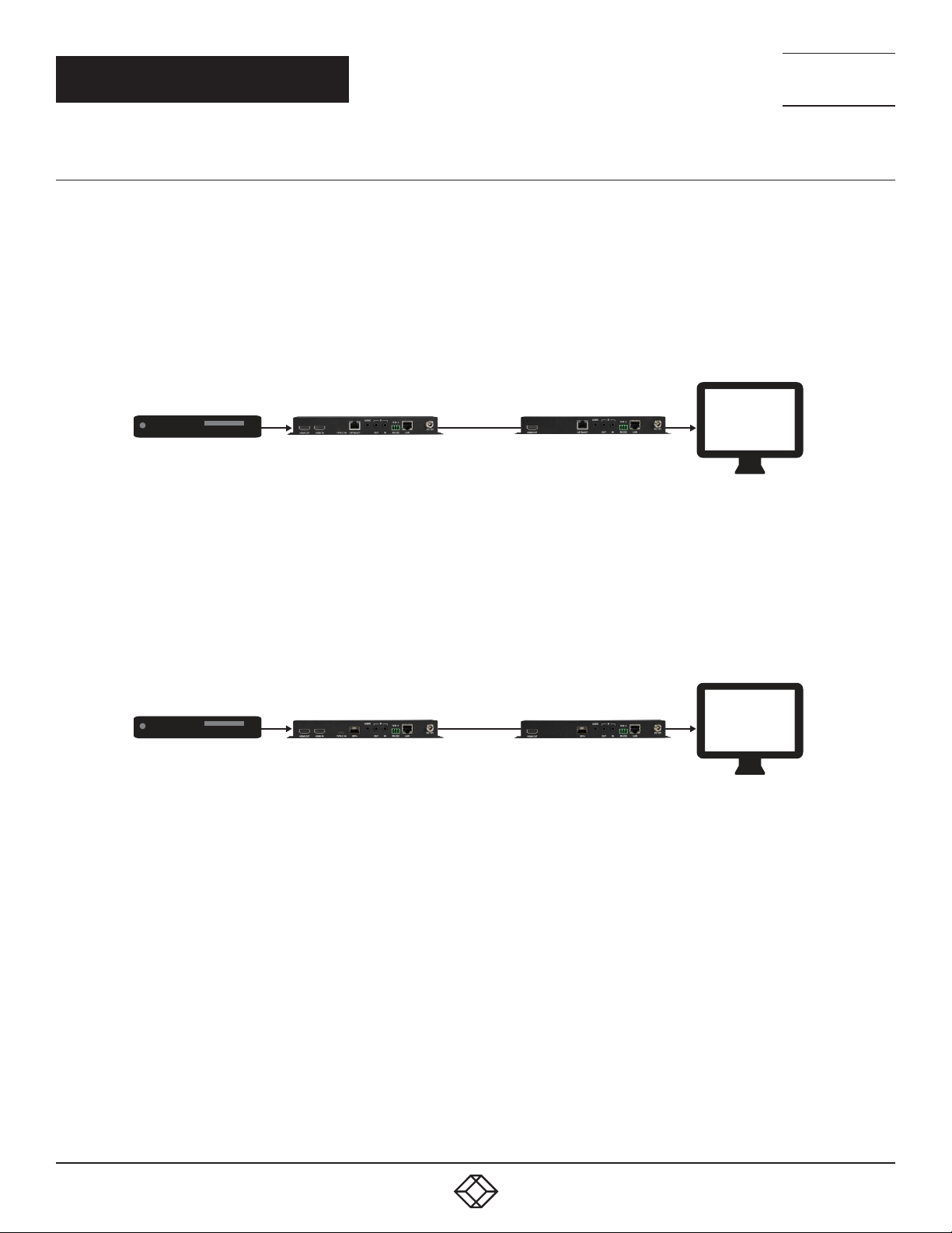
The most basic extension conguration available is a point-to-point system with a single transceiver unit acting as an encoder
connected directly to a single transceiver unit acting as a decoder. In this conguration the HDMI/DP input on the encoder side
is transmitted to the connected decoder side without modication to the audio or video format. The analog stereo audio input on
the encoder transfers audio directly to the analog stereo audio output on the decoder. The LAN, RS-232 and IR ports form direct
connections between the encoder and decoder as well. This conguration is ideal for basic video extension as well as remote KVM
applications.
Fiber Cable
FIG URE 1-16: COPP ER PO INT-TO-P OINT (ON E WAY)
Fiber Cable
FIGURE 1-17: FIBER POINT-TO-POINT (ONE WAY)
NOTE: These congurations do not use or require an external control center, such as the MCX Gen2 Controller, to function. No audio
insertion/extraction is performed in these congurations.
1. 87 7.8 7 7. 2 26 9 BLACKBOX.COM
19
Page 20
NEED HELP?
LEAV E TH E TEC H TO US
LIVE 24/7
CHAPTER 1: ENCODERS
1.6.6.2 POINT-TO-POINT (BI-DIRECTIONAL)
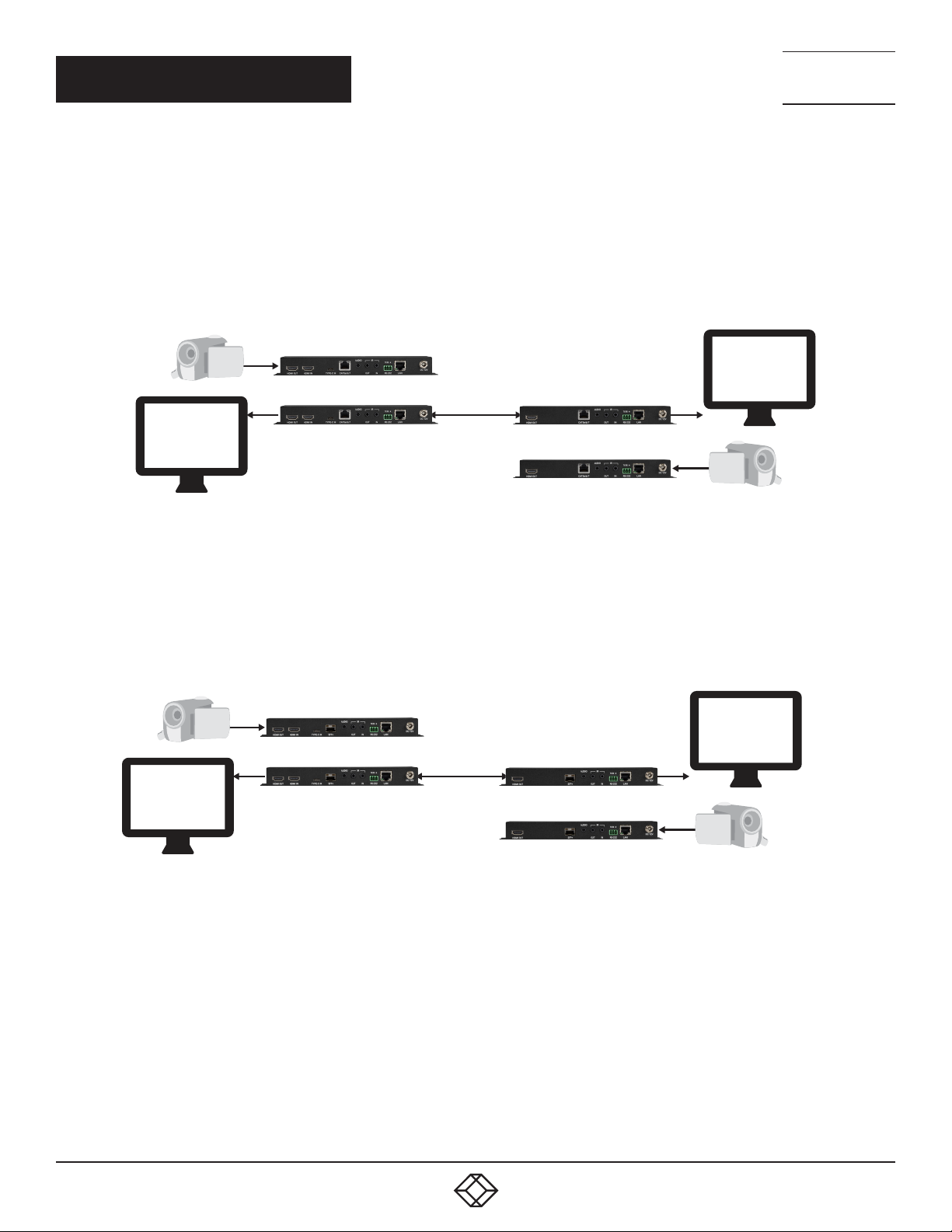
Another basic extension conguration is a bi-directional point-to-point system with the transceiver units at each end acting as both an
encoder and a decoder. In this conguration the HDMI/DP input on each side is transmitted to the opposite end of the connection for
output without modication to the audio or video format. The analog audio, LAN, RS-232 and IR ports form direct connections between
both ends as well. This conguration is ideal for long distance, secure, xed-point video conferencing applications.
Fiber cable
TECHNICAL
SUPPORT
1. 8 7 7. 8 7 7. 2 2 6 9
FIGURE 1-18: COPPER POINT-TO-POINT (BI-DIRECTIONAL)
Fiber cable
FIGURE 1-19: FIBER POINT-TO-POINT (BI-DIRECTIONAL)
NOTE: These congurations do not use or require an external control center, such as the MCX Gen2 Controller, to function. No audio
insertion/extraction is performed in these congurations.
20
1. 87 7.8 7 7. 2 26 9 BLACKBOX.COM
Page 21
NEED HELP?
LEAV E TH E TEC H TO US
LIVE 24/7
CHAPTER 1: ENCODERS
TECHNICAL
SUPPORT
1. 8 7 7. 8 7 7. 2 2 6 9
1.6.7 ADVANCED AV EXTENSION
1.6.7.1 MCX GEN2 CONTROLLER
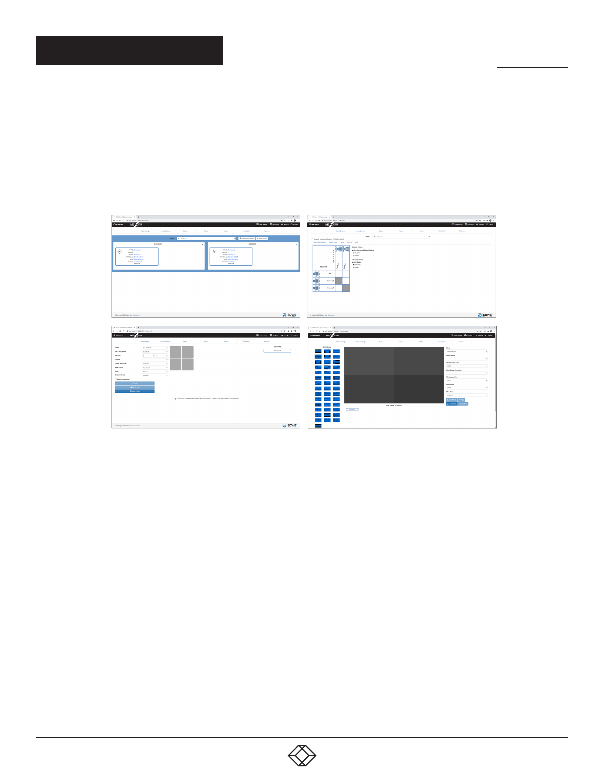
The MCX Gen2 Controller is a hardware solution designed to provide a unied and easy method to access and control all of the
encoders and decoders in a system. It provides a user-friendly, and operating system agnostic, web-based interface allowing easy
control over all of the most critical functions within a distribution system.
The MCX Gen2 hardware is an optional component and is not included with individual encoder, decoder, or transceiver units. Please
contact your authorized dealer for more information.
FIGURE 1-20: SAMPLE MCX GEN2 CONTROLLER SCREENSHOTS
NOTE: Interface images are for example only and may differ from the delivered product.
1. 87 7.8 7 7. 2 26 9 BLACKBOX.COM
21
Page 22
NEED HELP?
LEAV E TH E TEC H TO US
LIVE 24/7
CHAPTER 1: ENCODERS
1.6.7.2 CONFIGURATION EXAMPLES
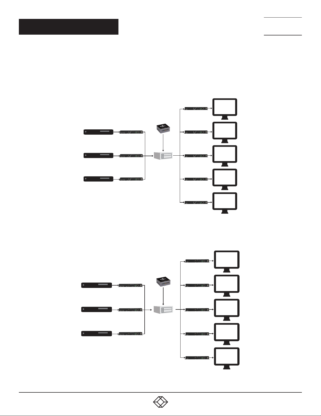
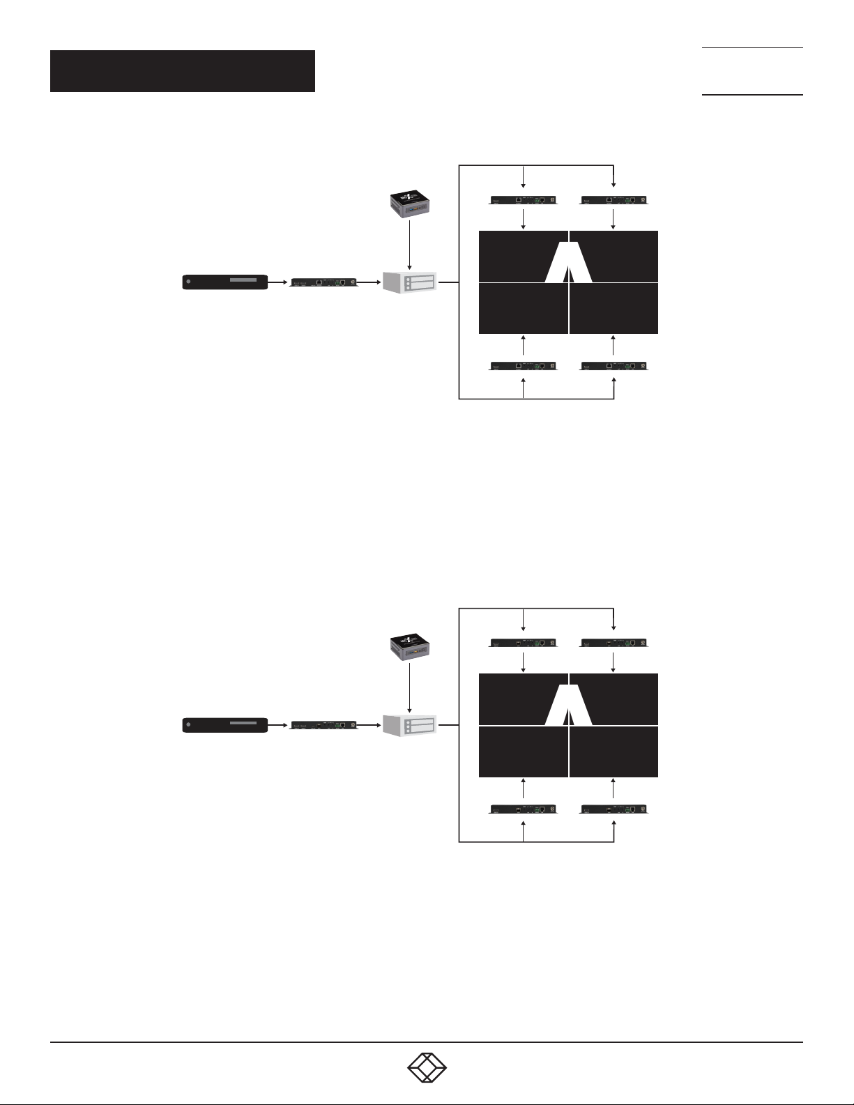
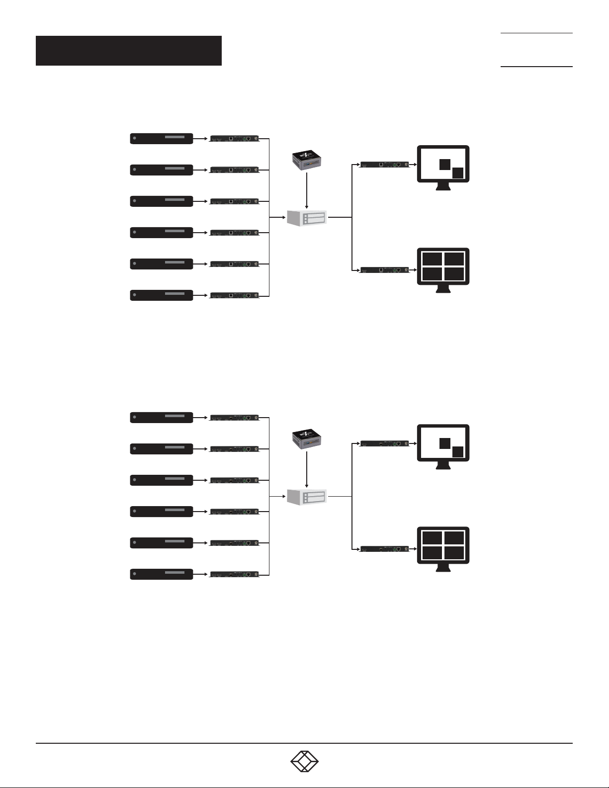
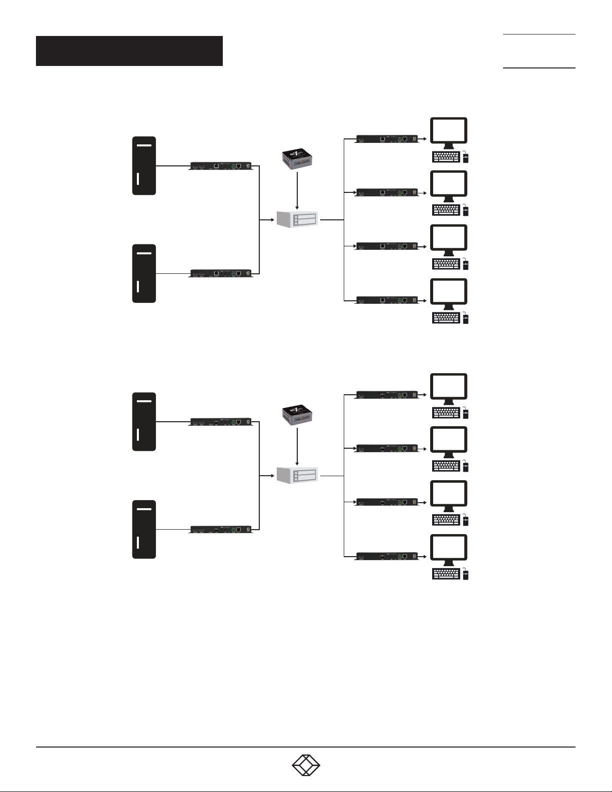
When combined with the MCX Gen2 Controller, and a 10 Gigabit ber Ethernet switch, this extension system gains a large number
of additional conguration options including: multi-in/multi-out matrix switching with breakaway audio, video wall creation, and a
multiview output mode. Audio extraction and embedding is fully controllable. Additionally, audio, USB, IR, and RS-232 routing can be
fully controlled.
(1) Matrix Conguration
TECHNICAL
SUPPORT
1. 8 7 7. 8 7 7. 2 2 6 9
10GbE Fiber
Network Switch
FIGURE 1-21: COPPER MATRIX CONFIGURATION
22
10GbE Fiber
Network Switch
FIGURE 1-22: FIBER MATRIX CONFIGURATION
1. 87 7.8 7 7. 2 26 9 BLACKBOX.COM
Page 23
CHAPTER 1: ENCODERS
A
A
(2) Video Wall Conguration
10GbE Fiber
Network Switch
NEED HELP?
LEAV E TH E TEC H TO US
LIVE 24/7
TECHNICAL
SUPPORT
1. 8 7 7. 8 7 7. 2 2 6 9
FIGURE 1-23: COPPER VIDEO WALL CONFIGURATION
10GbE Fiber
Network Switch
FIGURE 1-24: FIBER VIDEO WALL CONFIGURATION
1. 87 7.8 7 7. 2 26 9 BLACKBOX.COM
23
Page 24
CHAPTER 1: ENCODERS
(3) Multiview (PiP/PoP/Quad/Etc.) Conguration
10GbE Fiber
Network Switch
1
3 4
5 6
NEED HELP?
LEAV E TH E TEC H TO US
LIVE 24/7
TECHNICAL
SUPPORT
1. 8 7 7. 8 7 7. 2 2 6 9
2
FIGURE 1-25: COPPER MULTIVIEW (PIP/POP/QUAD/ETC.) CONFIGURATION
10GbE Fiber
Network Switch
1
2
3 4
5 6
24
FIGURE 1-26: FIBER MULTIVIEW (PIP/POP/QUAD/ETC.) CONFIGURATION
1. 87 7.8 7 7. 2 26 9 BLACKBOX.COM
Page 25
CHAPTER 1: ENCODERS
(4) KVM Switch Conguration
10GbE Fiber
Network Switch
NEED HELP?
LEAV E TH E TEC H TO US
LIVE 24/7
TECHNICAL
SUPPORT
1. 8 7 7. 8 7 7. 2 2 6 9
FIGURE 1-27: COPPER KVM SWITCH CONFIGURATION
10GbE Fiber
Network Switch
FIGURE 1-28: FIBER KVM SWITCH CONFIGURATION
1. 87 7.8 7 7. 2 26 9 BLACKBOX.COM
25
Page 26
CHAPTER 1: ENCODERS
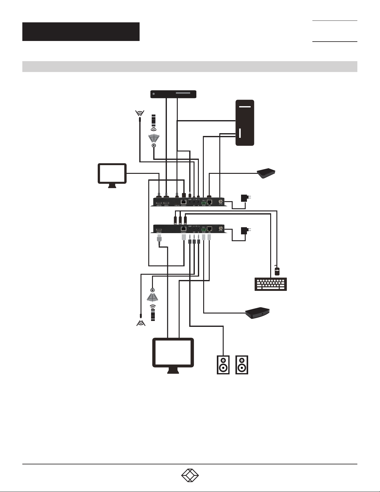
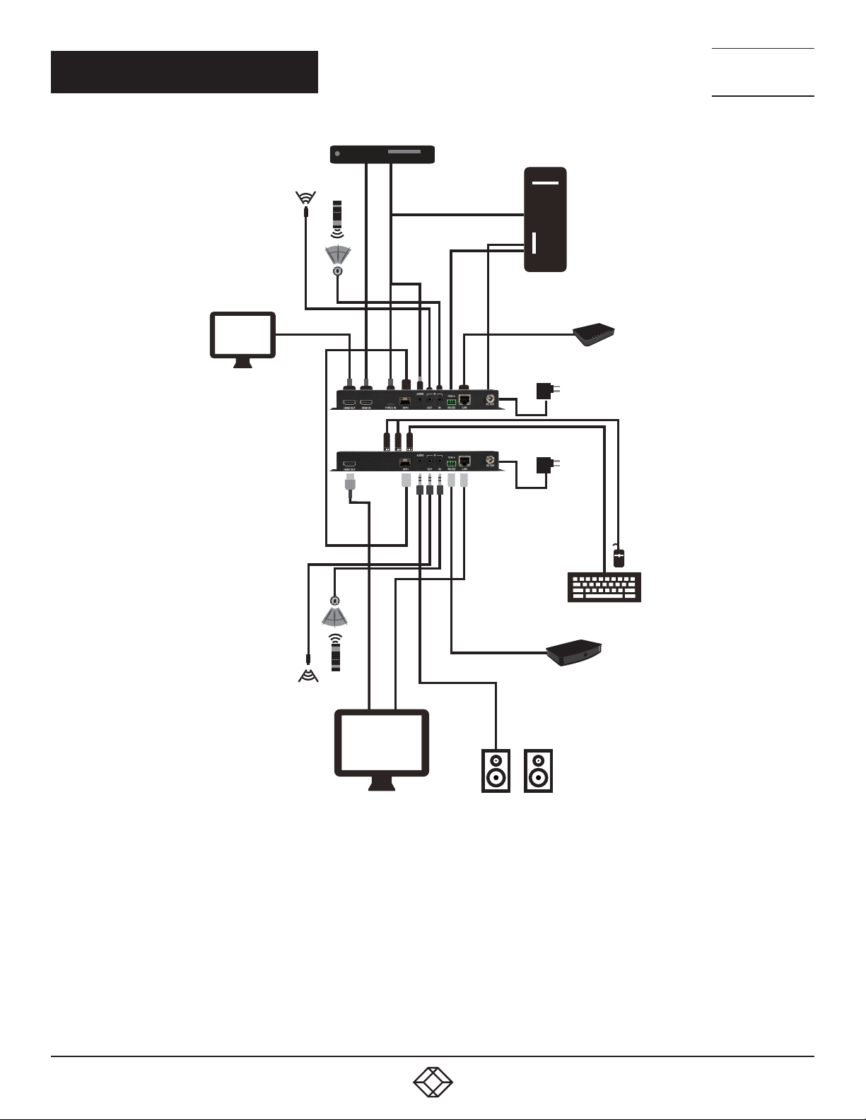
1.7 CONNECTION DIAGRAMS
Media Player
HDMI
Input
Stereo
Input
PC
NEED HELP?
LEAV E TH E TEC H TO US
LIVE 24/7
TECHNICAL
SUPPORT
1. 8 7 7. 8 7 7. 2 2 6 9
IR Input &
Output
Local Monitor
IR Input &
Output
HDMI
Output
Cat6A
Cable
HDMI
Output
Typ e C
Input
USB
RS-232
LAN
RS-232
Router
Power
Supply
Power
Supply
USB
26
LAN
Smart TV Powered Speakers
FIGURE 1-29: COPPER CONNECTION DIAGRAM
1. 87 7.8 7 7. 2 26 9 BLACKBOX.COM
Stereo
Output
Serial Controlled
Device
Page 27
CHAPTER 1: ENCODERS
Media Player
HDMI
Input
Stereo
Input
PC
NEED HELP?
LEAV E TH E TEC H TO US
LIVE 24/7
TECHNICAL
SUPPORT
1. 8 7 7. 8 7 7. 2 2 6 9
IR Input &
Output
Local Monitor
IR Input &
Output
HDMI
Output
Fiber
Cable
HDMI
Output
Typ e C
Input
USB
RS-232
LAN
RS-232
Router
Power
Supply
Power
Supply
USB
Serial Controlled
LAN
Smart TV Powered Speakers
FIGURE 1-30: FIBER CONNECTION DIAGR AM
1. 87 7.8 7 7. 2 26 9 BLACKBOX.COM
Stereo
Output
Device
27
Page 28

CHAPTER 1: ENCODERS
1.8 SPECIFICATIONS
TABLE 1-10. GENERAL SPECIFICATIONS
SPECIFICATION DESCRIPTION
HDMI Bandwidth 18 Gbps
10GbE Bandwidth 10 Gbps
Input Ports
Output Ports (1) HDMI (Type A) female
Bi-Directional Port (1) Stereo Audio (3.5mm) female
Pass-Through Ports
IR Frequency 38kHz
Baud Rate 57600 (default), up to 115200 bps
Power Supply 12V/3A DC (US/EU standards, CE/FCC/UL certified)
ESD Protection (HBM)
Dimensions
Weight 916g
Chassis Metal Metal (steel)
Chassis Color Black
Operating Temperature 0 to 40˚C (32 to 104˚F)
Storage Temperature -20 to 60˚C (-4 to to 140˚F)
Relative Humidity 20 to 90% RH (Non-condensing)
Power Consumption 14.3w (for copper); 18.51w (for fiber)
(1) HDMI (Type A) female;
(1) Type C female
(1) 10GbE LAN (RJ-45 for copper; SFP+ for fiber) female;
(1) IR (3.5mm) female;
(1) RS-232 (3-pin terminal block) female;
(1) LAN (RJ-45) female
±8kV (air discharge);
±4kV (contact discharge);
215mm x 25mm x 108mm (case only);
215mm x 25mm x 116.7 mm (all inclusive)
NEED HELP?
LEAV E TH E TEC H TO US
LIVE 24/7
TECHNICAL
SUPPORT
1. 8 7 7. 8 7 7. 2 2 6 9
28
1. 87 7.8 7 7. 2 26 9 BLACKBOX.COM
Page 29

CHAPTER 1: ENCODERS
SUPPORTED RESOLUTIONS (HZ)
720×400p@70/85
640×480p@60/72/75/85
720×480i@60
720×480p@60
720×576i@50
720×576p@50
800×600p@56/60/72/75/85
848×480p@60
1024×76 8p@60/70/75/85
1152 ×864p@75
128 0×720 p@50/60
128 0×76 8p@60/75/85
1280×800p@60/75/85
1280×960p@60/85
128 0×1024p@60/75/85
1360×768p@60
1366×768p@60
140 0×105 0p@60
1440×900p@60/75
1600×900p@60RB
1600×1200p@60
168 0×105 0p@60
1920×1080 i@50/60
1920×1080 p@24/25/30
1920×1080 p@50/60
1920×1200p@60RB
2560×1440p@60RB
2560×1600p@60RB
2048×1080p@24/25/30
2048×1080p@50/60
3840×2160p@24/25/30
3840×2160p@50/60 (4:2:0)
3840×2160p@24, HDR10
3840×2160p@50/60 (4:2:0), HDR10
3840×2160p@50/60
40 96×2160 p@24/25/30
40 96×2160 p@50/60 (4:2:0)
40 96×2160 p@24, HDR10
TABLE 1-11. VIDEO SPECIFICATIONS
INPUT OUTPUT
HDMI TYPE-C 10GBE HDMI
NEED HELP?
LEAV E TH E TEC H TO US
LIVE 24/7
TECHNICAL
SUPPORT
1. 8 7 7. 8 7 7. 2 2 6 9
1. 87 7.8 7 7. 2 26 9 BLACKBOX.COM
29
Page 30

CHAPTER 1: ENCODERS
NEED HELP?
LEAV E TH E TEC H TO US
LIVE 24/7
TECHNICAL
SUPPORT
1. 8 7 7. 8 7 7. 2 2 6 9
TABLE 1-11. VIDEO SPECIFICATIONS CONTINUED
SUPPORTED RESOLUTIONS (HZ)
40 96×2160 p@50/60 (4:2:0), H DR10
40 96×2160 p@50/60
TABLE 1-11. VIDEO SPECIFICATIONS
INPUT OUTPUT
HDMI TYPE-C 10GBE HDMI
30
1. 87 7.8 7 7. 2 26 9 BLACKBOX.COM
Page 31

CHAPTER 1: ENCODERS
TABLE 1-12. DIGITAL AUDIO HDMI INPUT SPECIFICATIONS
SPECIFICATION DESCRIPTION
LPCM
Max Channels 8 channels
Sampling Rate (kHz) 32, 44.1, 48
Bitstream
Supported Formats Standard and High Definition
TABLE 1-13. CAT5E/6/7 OUTPUT (COPPER)/FIBER OUTPUT (FIBER)
SPECIFICATION DESCRIPTION
LPCM
Max Channels 8 channels
Sampling Rate (kHz) 32, 44.1, 48
Bitstream
Supported Formats Standard and High Definition
NEED HELP?
LEAV E TH E TEC H TO US
LIVE 24/7
TECHNICAL
SUPPORT
1. 8 7 7. 8 7 7. 2 2 6 9
1. 87 7.8 7 7. 2 26 9 BLACKBOX.COM
31
Page 32

CHAPTER 1: ENCODERS
TABLE 1-14. ANALOG AUDIO INPUT SPECIFICATIONS
SPECIFICATION DESCRIPTION
Max Audio Level 1Vrms
Impedance 10kΩ
Typ e Unbalanced
TABLE 1-15. ANALOG AUDIO OUTPUT SPECIFICATIONS
SPECIFICATION DESCRIPTION
Max Audio Level 1Vrms
THD+N < −80dB@0dBFS 1kHz (A-wt)
SNR > 80dB@0dBFS
Frequency Response < ±1dB@20Hz~20kHz
Crosstalk < −80dB@10kHz
Impedance 470Ω
Typ e Unbalanced
NEED HELP?
LEAV E TH E TEC H TO US
LIVE 24/7
TECHNICAL
SUPPORT
1. 8 7 7. 8 7 7. 2 2 6 9
32
1. 87 7.8 7 7. 2 26 9 BLACKBOX.COM
Page 33

CHAPTER 1: ENCODERS
CABLE LENGTH
HIGH SPEED HDMI CABLE
HDMI INPUT 15m 10m 5m 3m
HDMI OUTPUT 15m 10m 5m 3m
CATEGORY CABLE (COPPER)
CAT. 5 E / 6 100m 70m
CAT. 6A /7 100m
FIBER CABLE
MULTI-MODE FIBER (OM3) 300m
MULTI-MODE FIBER (OM4) 550m
SINGLE-MODE FIBER 30km
TABLE 1-16. CABLE SPECIFICATIONS
1080P 4K30 4K60
8-BIT 12- BIT
(4:4:4)
8-BIT
(4:4:4)
8-BIT
NEED HELP?
LEAV E TH E TEC H TO US
LIVE 24/7
TECHNICAL
SUPPORT
1. 8 7 7. 8 7 7. 2 2 6 9
Bandwidth Category Examples:
1080p (FHD Video)
Up to 1080p@60Hz, 12-bit color
Data rates lower than 5.3Gbps or below 225MHz TMDS clock
4K30 (4K UHD Video)
4K@24/25/30Hz & 4K@50/60Hz (4:2:0), 8-bit color
Data rates higher than 5.3Gbps or above 225MHz TMDS clock but below 10.2Gbps
4K60 (4K UHD
+
Video)
4K@50/60Hz (4:4:4, 8-bit)
4K@50/60Hz (4:2:0, 10-bit HDR)
Data rates higher than 10.2Gbps
1. 87 7.8 7 7. 2 26 9 BLACKBOX.COM
33
Page 34

NEED HELP?
LEAV E TH E TEC H TO US
LIVE 24/7
CHAPTER 2: DECODERS
TECHNICAL
SUPPORT
1. 8 7 7. 8 7 7. 2 2 6 9
2.1 INTRODUCTION
This Decoder is designed for high-quality, IP routable, AV extension with virtually zero latency. The unit is capable of receiving AV and
other data for long extension, enhancing the exibility of any installation. By using a sophisticated ultra-light compression scheme
(lossless for most content) it is a great solution for extending 4K audio/video streams (HDMI or DisplayPort) and data. Advanced
HDMI content, such as HDR (High Dynamic Range), 10-bit color and multi-channel HD Bitstream audio, can be transmitted in passthrough mode.
For the copper decoder, the use of high-quality 10-Gbps Ethernet ports and Cat.6A or better cable allows for point-to-point
transmission of the video signal up to 100m.
For the ber decoder, the use of interchangeable, eld replaceable, SFP+ modules allows for transmission distances of up to 30km.
(Maximum transmission distance depends on the SFP+ modules used.)
Multiple control and data signals may also be transmitted along with the audio and video, including IR, RS-232, and Ethernet.
When combined with the optional MCX Gen2 Controller, or control software, the functionality of the Transceiver expands
exponentially. Multiple encoders/decoders may be combined with one or more 10-Gigabit ber Ethernet switches. The units can be
used together to form a distributed video matrix, a multi-viewer system, or a video wall system. This AV network capability provides
exibility in large event installations.
The integrated USB hub of each decoder can be congured to be in USB Host or Device Mode. It can function as a simple point-topoint KVM extension, freely routed between any two endpoints, or it can be congured into a special “Simultaneous” mode, allowing
up to 7 Host Mode units to extend their USB ports to a single Device Mode unit. This type of USB KVM routing exibility enables a
wide range of multi-user, control room, or on-demand installation scenarios.
The built-in EDID and HDCP management functionality enables the unit to t into every video distribution situation. Basic
conguration of the unit can be achieved via front panel buttons with an OSD (On-Screen Display). Advanced control requires the
optional MCX Gen2 controller, or control software, and a LAN connection.
2.2 APPLICATIONS
Video, Audio, LAN, IR, and USB over Copper Cable or Fiber extension
Long distance data and video transmission immune to RF interference
Point-to-Point Secure Video Conferencing
Hotel or convention center display
Multi-monitor broadcast
Distributed video matrix system
Distributed video wall system
Remote KVM system control
2.3 PACKAGE CONTENTS
(1) UHD+ Copper or Fiber Receiver
(1) 12V/3A DC Power Adapter
(1) Power CordMulti-monitor broadcast
Distributed video matrix system
Distributed video wall system
34
1. 87 7.8 7 7. 2 26 9 BLACKBOX.COM
Page 35

NEED HELP?
LEAV E TH E TEC H TO US
LIVE 24/7
CHAPTER 2: DECODERS
TECHNICAL
SUPPORT
1. 8 7 7. 8 7 7. 2 2 6 9
2.4 SYSTEM REQUIREMENTS
HDMI or DisplayPort source equipment, such as a media player, video game console, PC, or set-top box
HDMI receiving equipment, such as an HDTV, monitor, or audio amplifier
Analog audio receiving equipment, such as headphones, an audio amplifier, or powered speakers
A 10-Gbps Ethernet network switch with jumbo frame and IGMP snooping support is required for distributed video systems.
(Optional, required for multi-encoder/decoder copper systems)
A 10-Gbps fiber Ethernet network switch with jumbo frame and IGMP snooping support is required for distributed video systems.
(Optional, required for multi-encoder/decoder fiber systems)
IEEE 802.3ae compatible SFP+ fiber module supporting a dual-optical fiber connection style, such as LC, or a pre-terminated
crossover dual-optical fiber cable (required for fiber decoder)
NOTE: Single-mode and multi-mode support is dependent on the SFP+ modules used
MCX Gen2 Controller or control software to configure distributed matrix, video wall or multi-view systems (Optional)
1. 87 7.8 7 7. 2 26 9 BLACKBOX.COM
35
Page 36

NEED HELP?
LEAV E TH E TEC H TO US
LIVE 24/7
CHAPTER 2: DECODERS
TECHNICAL
SUPPORT
1. 8 7 7. 8 7 7. 2 2 6 9
2.5 FEATURES
HDMI 2.0 and DVI 1.0 compatible
HDCP 2.2 and HDCP 1.x compliant
(1) HDMI -output, (1) Cat5e/6/7 input, (1) analog stereo
IP switchable with minimum latency (requires optional MCX Gen2 Controller or control software)
Ultra-light compression, lossless for most content
Extension up to 100m in point-to-point mode (with Cat.6A cable for copper decoder)
Extension up to 30km (Maximum distance depends on the SFP+ module and type of fiber used for fiber decoder.)
Supports independent breakaway A/V matrix switching with minimum latency, video wall generation, and multi-view compositing
(requires optional MCX Gen2 Controller/control software)
Supports pass-through of 10/12-bit HDR sources (Point-to-Point and Bypass modes only)
Supports pass-through of audio formats including LPCM (up to eight channels), Bitstream and HD Bitstream from HDMI or DP
sources
AV, IR, RS-232, USB 2.0, and Ethernet extension
Unit can be powered directly by PoE when connected to a 10 Gigabit Ethernet (10GbE) switch that provides PoE (802.3at) (for
copper decoder)
Signal transmission interfaces with 10-Gigabit Ethernet switches via XFI (IEEE 802.3ae) compatible SFP+ fiber modules (for fiber
decoder)
Basic configuration via front panel buttons with an OSD
Supports the use of an external control center (MCX Gen2 Controller) or control software to provide expanded functionality (Contact
Black Box for more information.)
36
1. 87 7.8 7 7. 2 26 9 BLACKBOX.COM
Page 37
CHAPTER 2: DECODERS
2.6 OPERATION CONTROLS AND FUNCTIONS
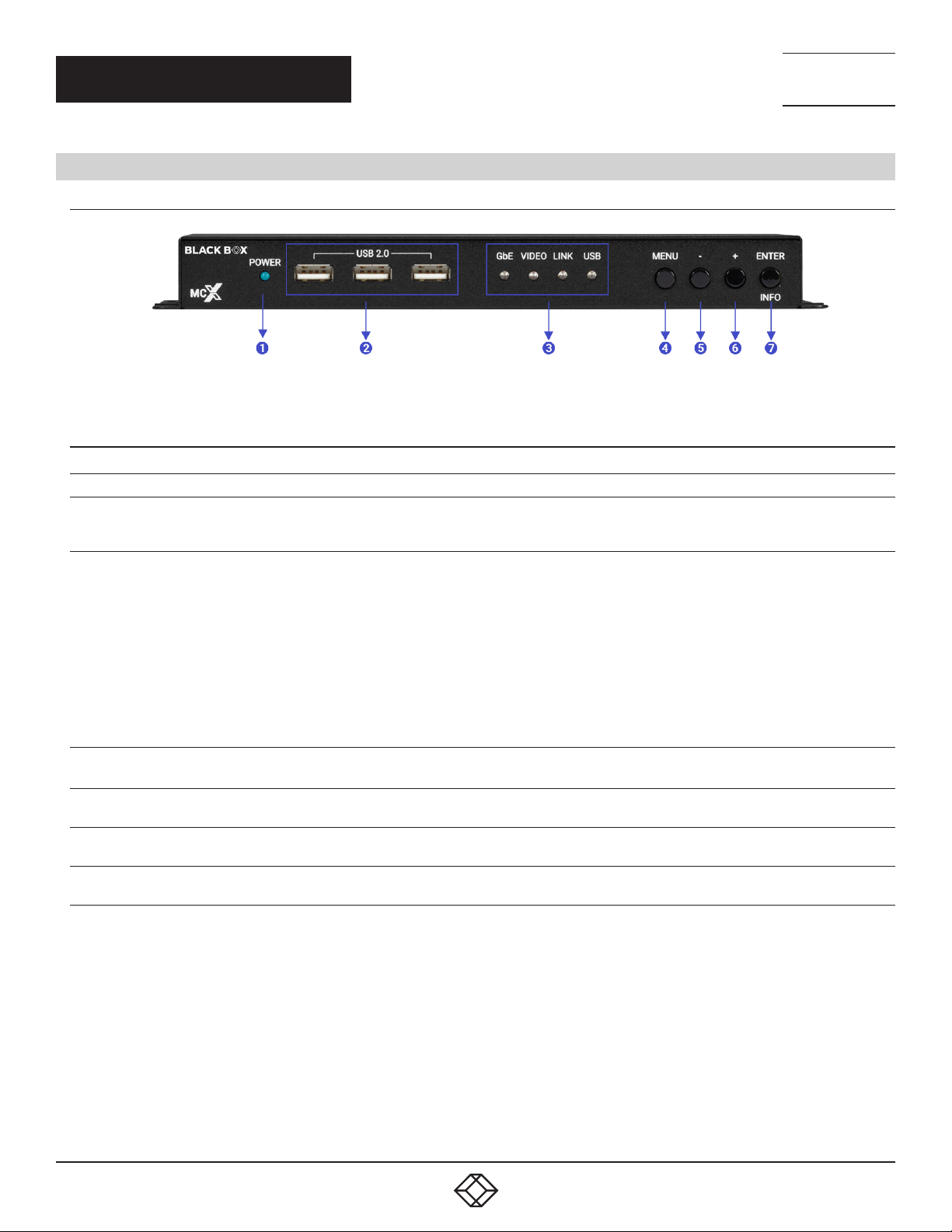
2.6.1FRONT PANEL
FIGURE 2-1: FRONT PANEL
TABLE 2-1. FRONT-PANEL COMPONENTS
NUMBER IN FIGURE 2-1 COMPONENT DESCRIPTION
1 (1) Power LED indicator Lights ON or OFF for Power
Connect directly to standard USB devices, such as a mouse, keyboard or ash
2 (3) USB 2.0 (Type A) ports
3 (1) Status LED Block
drive to extend their USB functionality to the currently active/routed USB Device
Mode transceiver.
GbE LED: This LED will illuminate and blink to indicate a live and active
connection on the local gigabit Ethernet port.
VIDEO LED: This LED will illuminate Green when a video signal is live on the
optical ber streaming port or illuminate Amber when streaming a detected input
stream. When no video is active, the LED will remain off, even if the streaming
connection is valid.
LINK LED: These LEDs will illuminate and blink to indicate data transmission and
reception activity across the optical ber streaming connection.
USB LED: This LED will illuminate when the unit’s USB ports have successfully
paired with the USB ports on another unit. This LED will blink if the unit’s USB
ports are not currently paired and are in stand-by mode.
NEED HELP?
LEAV E TH E TEC H TO US
LIVE 24/7
TECHNICAL
SUPPORT
1. 8 7 7. 8 7 7. 2 2 6 9
4 (1) Menu button Press to enter the OSD menu, or to back out from menu items.
5 (1) Menu button: - Minus button
6 (1) Menu button: + button
7 (1) Enter/Info button
1. 87 7.8 7 7. 2 26 9 BLACKBOX.COM
Press to move up or adjust selections within OSD menus. When not in a menu,
press to manually switch between encoder source inputs.
Press to move up or adjust selections within OSD menus. When not in a menu,
press to manually switch between decoder source inputs.
When inside an OSD menu, press to confirm a selection or to go deeper into a menu
item. When not in a menu, press to activate the Information OSD.
37
Page 38
CHAPTER 2: DECODERS
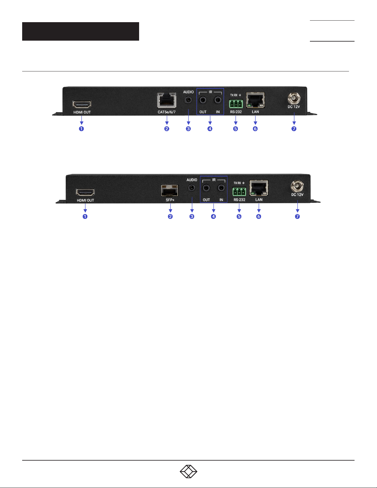
2.6.2 REAR PANEL
FIGURE 2-2: REAR PANEL (COPPER)
NEED HELP?
LEAV E TH E TEC H TO US
LIVE 24/7
TECHNICAL
SUPPORT
1. 8 7 7. 8 7 7. 2 2 6 9
FIGURE 2-3: REAR PANEL (FIBER)
38
1. 87 7.8 7 7. 2 26 9 BLACKBOX.COM
Page 39

CHAPTER 2: DECODERS
TABLE 2-2. REAR-PANEL COMPONENTS
NEED HELP?
LEAV E TH E TEC H TO US
LIVE 24/7
TECHNICAL
SUPPORT
1. 8 7 7. 8 7 7. 2 2 6 9
NUMBER IN FIGURE
2-2/2-3
1 (1) HDMI Out Port Connect to an HDMI TV, monitor, or amplifier for digital video and audio output.
2
3 (1) Audio port
COMPONENT DESCRIPTION
Connect directly to a compatible encoder/decoder for point-to-point extension, or to a
10 Gigabit Ethernet switch for distributed matrixing (requires MCX Gen2 Controller or
(1) Cat5E/6/7 port
OR
(1) SFP+ port
control software) with a single Cat.5e/6/7 cable for extension of all data signals (for
copper decoder).
NOTE: If the connected network switch supports the IEEE 802.3at-2009 PoE
(Power over Ethernet) standard, this unit can optionally be powered directly via this
Ethernet port.
Insert a standard SFP+ module and connect the appropriate optical cable to allow
data transmission to a compatible transceiver or to a 10-gigabit optical fiber network
switch (for fiber decoder).
NOTE: The SFP+ module must support a dual-optical fiber connection style, such
as LC, or be pre-terminated dual-optical fiber cables. Single-mode and multi-mode
support is dependent on the SFP+ modules used.
As OUT: Connect to powered speakers or an amplifier for stereo analog audio output.
As IN: Connect to the stereo analog output of a device, such as a CD player or PC.
NOTE: When the encoder and decoder are connected directly in a point-to-point
configuration, audio is routed directly to the opposite end’s Ports. Free routing can
only be configured by use of the optional MCX Gen2 Master Controller or control
software.
OUT Port: Connect to an IR Blaster to broadcast IR signals from a connected
transceiver to devices within direct line-of sight of the IR Blaster.
4 (2) IR ports
5 (1) RS-232 Terminal Block
6 LAN Port
7 DC 12V Port
1. 87 7.8 7 7. 2 26 9 BLACKBOX.COM
IN Port: Connect to an IR Extender to receive IR control signals and extend them to
devices connected to a connected transceiver. Ensure that the remote being used is
within direct line-of-sight of the IR Extender.
NOTE: Currently, only 38KHz IR signal extension is supported.
Connect directly to a PC, laptop or serial controllable device with a 3-pin adapter cable
to extend the RS-232 signal between transceivers.
Connect to an Ethernet supporting device or to your local network as appropriate to
extend the network between transceivers.
Plug the 12V DC power adapter into this port and connect it to an AC wall outlet for
power.
39
Page 40
CHAPTER 2: DECODERS
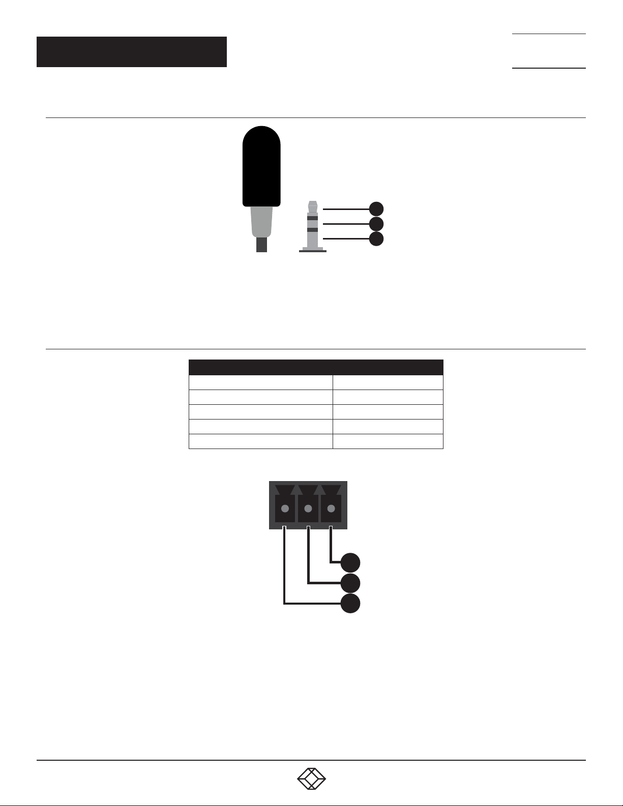
2.6.3 IR CABLE PINOUTS
IR Blaster Cable
1
2
3
FIGURE 2-4: IR BLASTER CABLE PINOUTS
Power
Infrared
Not Used
NEED HELP?
LEAV E TH E TEC H TO US
LIVE 24/7
TECHNICAL
SUPPORT
1. 8 7 7. 8 7 7. 2 2 6 9
2.6.4 RS-232 PINOUT AND DEFAULTS
SERIAL PORT DEFAULT SETTINGS
BA U D RATE
DATA BIT S 8
PARITY BITS NONE
STOP BITS 1
FLOW CONTROL NONE
FIGURE 2-5: SERIAL PORT DEFAULT SETTINGS
3-PIN TERMINAL BLOCK
57600
GND
1
RxD
2
TxD
FIGURE 2-6: 3-PIN TERMINAL BLOCK
3
NOTE: The default Serial Port baud rate can only be changed by use of the optional MCX Gen2 Controller or control software.
40
1. 87 7.8 7 7. 2 26 9 BLACKBOX.COM
Page 41

NEED HELP?
LEAV E TH E TEC H TO US
LIVE 24/7
CHAPTER 2: DECODERS
TECHNICAL
SUPPORT
1. 8 7 7. 8 7 7. 2 2 6 9
2.6.5 OSD MENU
All functions of this unit can be controlled by using the OSD (On Screen Display) which is activated by pressing the [MENU] button on
the front of the unit. Use the [+] (PLUS), [−] (MINUS), and [ENTER] buttons to navigate the OSD menu. Press the [MENU] button to back
out from any menu item and then press it again to close the menu.
MAIN MENU
OSD
EDID
HDCP
DEVICE SETTING
INFORMATION
USB INFORMATION
FACTORY SETTING
FIGURE 2-7: MAIN MENU
The individual functions of the OSD will be introduced in the following section. Items marked in BOLD are the factory default settings.
1. 87 7.8 7 7. 2 26 9 BLACKBOX.COM
41
Page 42

CHAPTER 2: DECODERS
OSD
2ND LEVEL 3RD LEVEL
DISPLAY INFORMATION
ON
OFF
INFORMATION TIMEOUT OFF
10~40 S E C [10 SEC]
MENU TIMEOUT OFF
10~40 S E C [10 SEC]
MENU H POSITION 0~10 0 [10]
MENU V POSITION
FIGURE 2-8: OSD MENU
0~100 [10]
TABLE 2-3. OSD
NEED HELP?
LEAV E TH E TEC H TO US
LIVE 24/7
TECHNICAL
SUPPORT
1. 8 7 7. 8 7 7. 2 2 6 9
SECOND LEVEL IN FIGURE 2-8 SELECTION DESCRIPTION
Display Information On/Off Enable or disable the Information OSD.
Information Timeout Multiple Set the display timeout for the Information OSD.
Menu Timeout Multiple Set the display timeout for the OSD Menu.
Menu H position Multiple Set the horizontal position of the OSD Menu.
Menu V Position Multiple Set the horizontal position of the OSD Menu.
42
1. 87 7.8 7 7. 2 26 9 BLACKBOX.COM
Page 43

CHAPTER 2: DECODERS
EDID
2ND LEVEL 3RD LEVEL
HDMI EDID
TYPE C EDID INTERNAL 1 (FHD 2CH)
VOIP EDID
INTERNAL 1 (FHD 2CH)
INTERNAL 2 (FHD MCH)
INTERNAL 3 (UHD 2CH)
INTERNAL 4 (UHD MCH)
INTERNAL 5 (UHD+ 2CH)
INTERNAL 6 (UHD+ MCH)
EXTERNAL A [HDMI OUTPUT]
EXTERNAL B [VOIP OUTPUT]
USER 1
USER 2
INTERNAL 2 (FHD MCH)
INTERNAL 3 (UHD 2CH)
INTERNAL 4 (UHD MCH)
INTERNAL 5 (UHD+ 2CH)
INTERNAL 6 (UHD+ MCH)
EXTERNAL A [HDMI OUT]
EXTERNAL B [VOIP OUT]
USER 1
USER 2
EXTERNAL A
NEED HELP?
LEAV E TH E TEC H TO US
LIVE 24/7
TECHNICAL
SUPPORT
1. 8 7 7. 8 7 7. 2 2 6 9
Figure 2-9: EDID Menu
TABLE 2-4. EDID
SECOND LEVEL IN FIGURE 2-9 SELECTION DESCRIPTION
HDMI EDID Multiple Select the EDID to send to the unit’s HDMI input.
Type C EDID Multiple Select the EDID to send to the unit’s DisplayPort input.
VOIP EDIC Multiple
The EDID provided to Video over IP connections is always set to use the EDID
from the unit’s local HDMI output.
1. 87 7.8 7 7. 2 26 9 BLACKBOX.COM
43
Page 44

CHAPTER 2: DECODERS
This unit provides the following six default EDIDs:
UNIT’S DEFAULT EDIDS
FHD 2CH
FHD MCH
UHD 2CH
UHD MCH
UHD+ 2CH
UHD+ MCH
1920×1080P@60HZ (4.95GBPS), 8-BIT COLOR,
LPCM 2.0
1920×1080P@60HZ (4.95GBPS), 8-BIT COLOR,
LPCM 7.1 & BITSTREAM
3840×2160P@30HZ (10.2GBPS), 12-BIT DEEP COLOR,
LPCM 2.0
3840×2160P@30HZ (10.2GBPS), 12-BIT DEEP COLOR,
LPCM 7.1 & BITSTREAM
3840×2160P@60HZ (18GBPS), 12-BIT DEEP COLOR,
LPCM 2.0
3840×2160P@60HZ (18GBPS), 12-BIT DEEP COLOR,
LPCM 7.1 & BITSTREAM
FIGURE 2-10 DEFAULT EDIDS
NEED HELP?
LEAV E TH E TEC H TO US
LIVE 24/7
TECHNICAL
SUPPORT
1. 8 7 7. 8 7 7. 2 2 6 9
NOTE: In some rare cases it is possible for custom or external EDIDs to cause compatibility issues with certain sources. If this
happens, it is recommended to switch to one of the six default EDIDs for maximum compatibility.
44
1. 87 7.8 7 7. 2 26 9 BLACKBOX.COM
Page 45

CHAPTER 2: DECODERS
HDCP
2ND LEVEL 3RD LEVEL
HDMI HDCP
TYPE-C HDCP DISABLE
VOIP HDCP
DISABLE
FOLLOW OUT
FOLLOW IN
FOLLOW API
FOLLOW OUT
FOLLOW IN
FOLLOW API
FOLLOW IN
FIGURE 2-11 HDCP MENU
TABLE 2-5. HDCP
NEED HELP?
LEAV E TH E TEC H TO US
LIVE 24/7
TECHNICAL
SUPPORT
1. 8 7 7. 8 7 7. 2 2 6 9
SECOND LEVEL IN FIGURE 2-11 SELECTION DESCRIPTION
Selects the HDCP logic to use with the HDMI input.
Follow In: The input supports up to the HDCP version required by the
connected source.
Follow Out: The input supports up to the HDCP version supported by the
HDMI HDCP Multiple
Type C HDCP Multiple
connected display.
Disable: HDCP support is completely disabled.
Follow API: Uses the HDCP setting dened by the MCX Gen2 Controller or
control software.
NOTE: In a point-to-point conguration, “Follow API” will behave the same as
“Follow Out”, if the API hasn’t been manually redened.
Selects the HDCP logic to use with the DisplayPort input.
Follow In: The input supports up to the HDCP version required by the
connected source.
Follow Out: The input supports up to the HDCP version supported by the
connected display.
Disable: HDCP support is completely disabled.
Follow API: Uses the HDCP setting dened by the MCX Gen2 Controller or
control software.
NOTE: In a point-to-point conguration, “Follow API” will behave the same as
“Follow Out”, if the API hasn’t been manually redened.
VOIP EDID Standard The Video-over-IP HDCP behavior is always “Follow In.”
1. 87 7.8 7 7. 2 26 9 BLACKBOX.COM
45
Page 46

CHAPTER 2: DECODERS
DEVICE SETTING
2ND LEVEL 3RD LEVEL
STAT U S TRANSCEIVER
USB CONTROL
MODE
HOST
DEVICE
USB VIRTUAL HUB OFF
ON
HDMI OUT SOURCE
INPUT 1 (HDMI)
INPUT 2 (DP)
INPUT 3 (VOIP)
VOIP OUT SOURCE INPUT 1 (HDMI)
INPUT 2 (DP)
INPUT 3 (VOIP)
HDMI OUT AUTO
MODE
VOIP OUT AUTO
MODE
FIGURE 2-12: DEVICE SE TTING MENU
OFF
AUTO SWITCH
OFF
AUTO SWITCH
NEED HELP?
LEAV E TH E TEC H TO US
LIVE 24/7
TECHNICAL
SUPPORT
1. 8 7 7. 8 7 7. 2 2 6 9
TABLE 2-6. DEVICE SETTINGS
SECOND LEVEL IN FIGURE 2-12 SELECTION DESCRIPTION
Displays the unit’s current operational mode.
STAT U S Transceiver
USB Control Mode Multiple
USB Virtual hub Off/On
HDMI Out Source Multiple Select the input source to display on the HDMI output.
VOIP Out Source Multiple Select the input source to transmit as an AV over IP stream.
HDMI Out Auto Mode Off/Auto Switch
VOIP Out Auto Mode Off/Auto Switch
NOTE: Due to this unit’s support of bi-directional transmission, the
status will always be set to “Transceiver.”
Enable or disable the USB 2.0 (Mini-B) port for connection to USB host
devices, such as a PC or laptop. Selecting [Device] enables the USB 2.0
(Mini-B) port. Selecting [Host] disables the USB 2.0 (Mini-B) port.
NOTE: In a point-to-point extension conguration, only one of the two
transceivers should be set as a USB Device to avoid conicts.
Enables or disables the “simultaneous connection” USB mode which
allows the PC/Laptop connected to this unit to be paired with the USB
devices on up to seven “Host” mode transceivers.
NOTE: Only available when USB Control Mode is set to “Device”.
USB routing can only be congured by use of the optional MCX
Gen2 Controller or control software and is not valid in point-to-point
congurations.
Enable or disable the HDMI output’s automatic source selection mode.
When enabled, the unit will automatically switch the input routed to the
local HDMI output whenever a new source is detected or if the current
source is lost.
Enable or disable the AVoIP streaming output’s automatic source
selection mode. When enabled, the unit will switch the input routed to the
AVoIP output whenever a new source is detected or if the current source
is lost.
46
1. 87 7.8 7 7. 2 26 9 BLACKBOX.COM
Page 47

CHAPTER 2: DECODERS
INFORMATION
2ND LEVEL 3RD LEVEL
RESOLUTION
STAT U S
FW VERSION [CURRENT FIRMWARE VERSION]
IP
MAC
SN
FIGURE 2-13: INFORMATION MENU
SECOND LEVEL IN FIGURE 2-13 SELECTION DESCRIPTION
Resolution Default Displays the unit’s detected source resolution
Status Default Displays the unit’s transceiver mode
FW Version Default Displays the unit’s rmware version
IP Default Displays the unit’s IP address
MAC Default Displays the unit’s MAC address
SN Default Displays the unit’s serial number
[CURRENT SOURCE RESOLUTION]
[CURRENT TRANSCEIVER MODE]
[CURRENT IP ADDRESS]
[UNIT’S MAC ADDRESS]
[UNIT’S SERIAL NUMBER]
TABLE 2-7. INFORMATION
NEED HELP?
LEAV E TH E TEC H TO US
LIVE 24/7
TECHNICAL
SUPPORT
1. 8 7 7. 8 7 7. 2 2 6 9
1. 87 7.8 7 7. 2 26 9 BLACKBOX.COM
47
Page 48

CHAPTER 2: DECODERS
USB INFORMATION
2ND LEVEL 3RD LEVEL
IP MODE [UNIT’S USB IP MODE]
IP [UNIT’S USB IP ADDRESS]
MAC [UNIT’S USB MAC ADDRESS]
PAIR MAC 1
PAIR MAC 2
PAIR MAC 3
PAIR MAC 4
PAIR MAC 5
PAIR MAC 6
PAIR MAC 7
[USB MAC ADDRESSES OF
CONNECTED USB SOURCES]
FIGURE 2-14: USB INFORMATION MENU
NEED HELP?
LEAV E TH E TEC H TO US
LIVE 24/7
TECHNICAL
SUPPORT
1. 8 7 7. 8 7 7. 2 2 6 9
TABLE 2-8. USB INFORMATION
SECOND LEVEL IN FIGURE 2-14 SELECTION DESCRIPTION
IP Mode Default Displays the unit’s USB IP mode
IP Default Displays the unit’s USB IP address
MAC Default Displays the unit’s USB MAC address
PAIR MAC 1-7 Default Displays the unit’s USB addresses of connected USB sources
48
1. 87 7.8 7 7. 2 26 9 BLACKBOX.COM
Page 49

CHAPTER 2: DECODERS
FACTORY SETTING
2ND LEVEL 3RD LEVEL
ARE YOU SURE? NO
YES
FIGURE 2-15: FACTORY SETTING MENU
TABLE 2-9. FACTORY INFORMATION
SECOND LEVEL IN FIGURE 2-15 SELECTION DESCRIPTION
Selecting [Yes] will reset the unit’s settings back to their factory defaults.
Are you sure? No/Yes
Selecting [No] will keep the current settings.
NEED HELP?
LEAV E TH E TEC H TO US
LIVE 24/7
TECHNICAL
SUPPORT
1. 8 7 7. 8 7 7. 2 2 6 9
1. 87 7.8 7 7. 2 26 9 BLACKBOX.COM
49
Page 50
NEED HELP?
LEAV E TH E TEC H TO US
LIVE 24/7
CHAPTER 2: DECODERS
TECHNICAL
SUPPORT
1. 8 7 7. 8 7 7. 2 2 6 9
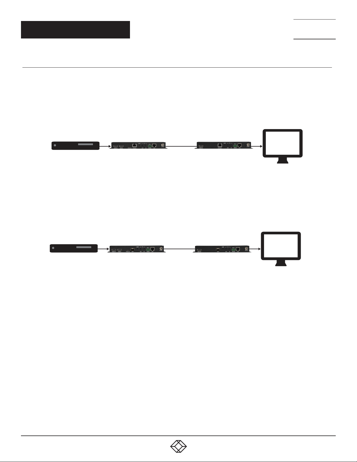
2.6.6 BASIC AV EXTENSION
2.6.6.1 POINT-TO-POINT (ONE WAY)
The most basic extension conguration available is a point-to-point system with a single transceiver unit acting as an encoder
connected directly to a single transceiver unit acting as a decoder. In this conguration the HDMI/DP input on the encoder side
is transmitted to the connected decoder side without modication to the audio or video format. The analog stereo audio input on
the encoder transfers audio directly to the analog stereo audio output on the decoder. The LAN, RS-232 and IR ports form direct
connections between the encoder and decoder as well. This conguration is ideal for basic video extension as well as remote KVM
applications.
Fiber Cable
FIGURE 2-16: COPPER POINT-TO-POINT (ONE WAY)
Fiber Cable
FIGURE 2-17: FIBER POINT-TO-POINT (ONE WAY)
NOTE: These congurations do not use or require an external control center, such as the MCX Gen2 Controller, to function. No audio
insertion/extraction is performed in these congurations.
50
1. 87 7.8 7 7. 2 26 9 BLACKBOX.COM
Page 51
NEED HELP?
LEAV E TH E TEC H TO US
LIVE 24/7
CHAPTER 2: DECODERS
TECHNICAL
SUPPORT
1. 8 7 7. 8 7 7. 2 2 6 9
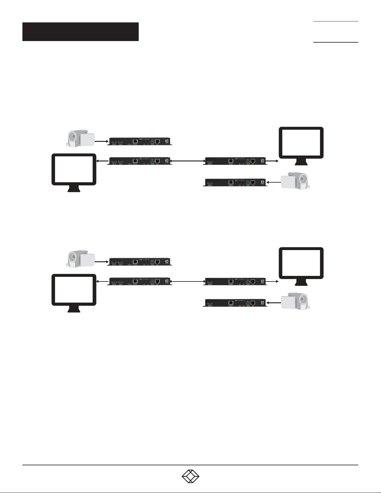
2.6.6.2 POINT-TO-POINT (BI-DIRECTIONAL)
Another basic extension conguration is a bi-directional point-to-point system with the transceiver units at each end acting as both
an encoder and a decoder. In this conguration the HDMI/DP input on each side is transmitted to the opposite end of the connection
for output without modication to the audio or video format. The analog audio, LAN, RS-232 and IR ports form direct connections
between both ends as well. This conguration is ideal for long distance, secure, xed-point video conferencing applications.
Fiber Cable
FIGURE 2-18: COPPER POINT-TO-POINT (BI-DIRECTIONAL)
Fiber Cable
FIGURE 2-19: FIBER POINT-TO-POINT (BI-DIRECTIONAL)
NOTE: These congurations do not use or require an external control center, such as the MCX Gen2 Controller, to function. No audio
insertion/extraction is performed in these congurations.
1. 87 7.8 7 7. 2 26 9 BLACKBOX.COM
51
Page 52
NEED HELP?
LEAV E TH E TEC H TO US
LIVE 24/7
CHAPTER 2: DECODERS
TECHNICAL
SUPPORT
1. 8 7 7. 8 7 7. 2 2 6 9
2.6.7 ADVANCED AV EXTENSION
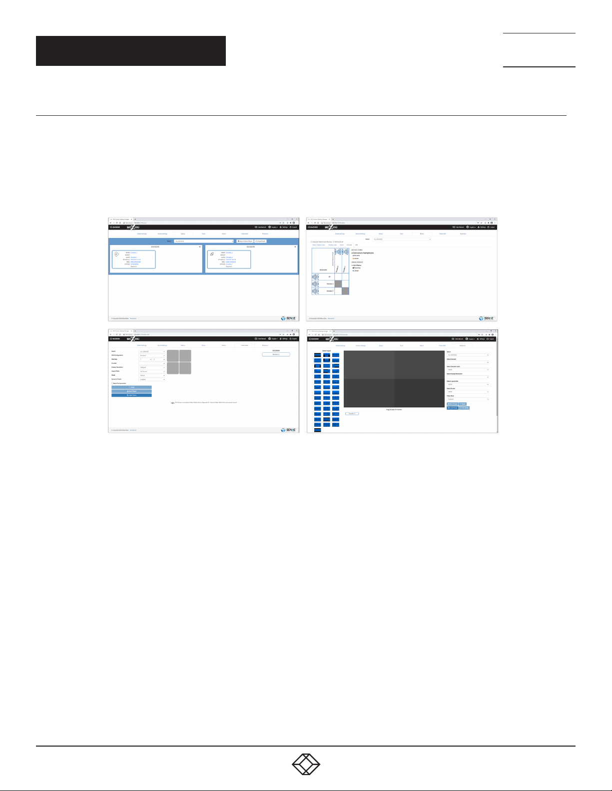
2.6.7.1 MCX GEN2 CONTROLLER
The MCX Gen2 Controller is a hardware solution designed to provide a unied and easy method to access and control all of the
encoders and decoders in a system. It provides a user-friendly, and operating system agnostic, web-based interface allowing easy
control over all of the most critical functions within a distribution system.
The MCX Gen2 Controller hardware is an optional component and is not included with individual encoder, decoder, or transceiver
units. Please contact your authorized dealer for more information.
FIGURE 2-20: SAMPLE MCX GEN2 CONTROLLER SCREENSHOTS.
NOTE: Interface images are for example only and may differ from the delivered product.
52
1. 87 7.8 7 7. 2 26 9 BLACKBOX.COM
Page 53
NEED HELP?
LEAV E TH E TEC H TO US
LIVE 24/7
CHAPTER 2: DECODERS
TECHNICAL
SUPPORT
1. 8 7 7. 8 7 7. 2 2 6 9
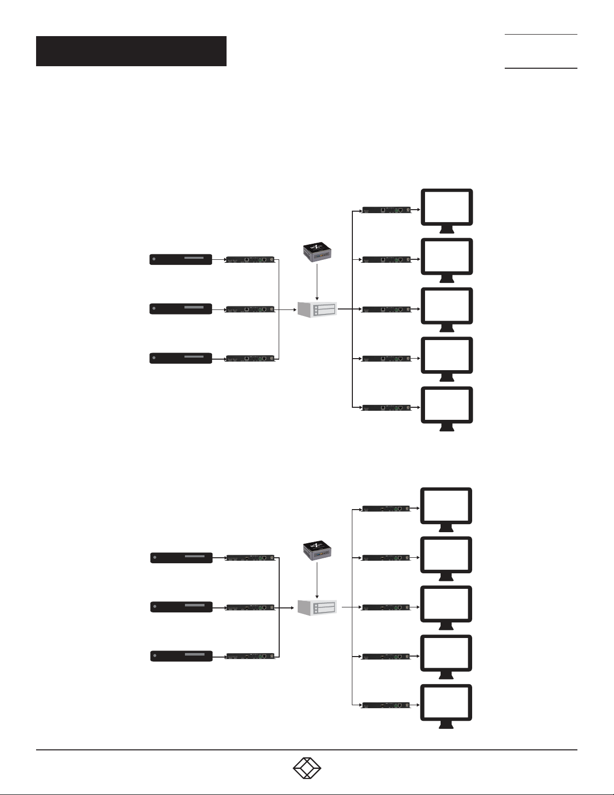
2.6.7.2 CONFIGURATION EXAMPLES
When combined with the MCX Gen2 Controller, and a 10 Gigabit ber Ethernet switch, this extension system gains a large number
of additional conguration options including: multi-in/multi-out matrix switching with breakaway audio, video wall creation, and a
multiview output mode. Audio extraction and embedding is fully controllable. Additionally, audio, USB, IR, and RS-232 routing can be
fully controlled.
(1) Matrix Conguration
10GbE Fiber
Network Switch
FIGURE 2-21: COPPER MATRIX CONFIGURATION
10GbE Fiber
Network Switch
FIGURE 2-22: FIBER MATRIX CONFIGURATION
1. 87 7.8 7 7. 2 26 9 BLACKBOX.COM
53
Page 54
CHAPTER 2: DECODERS
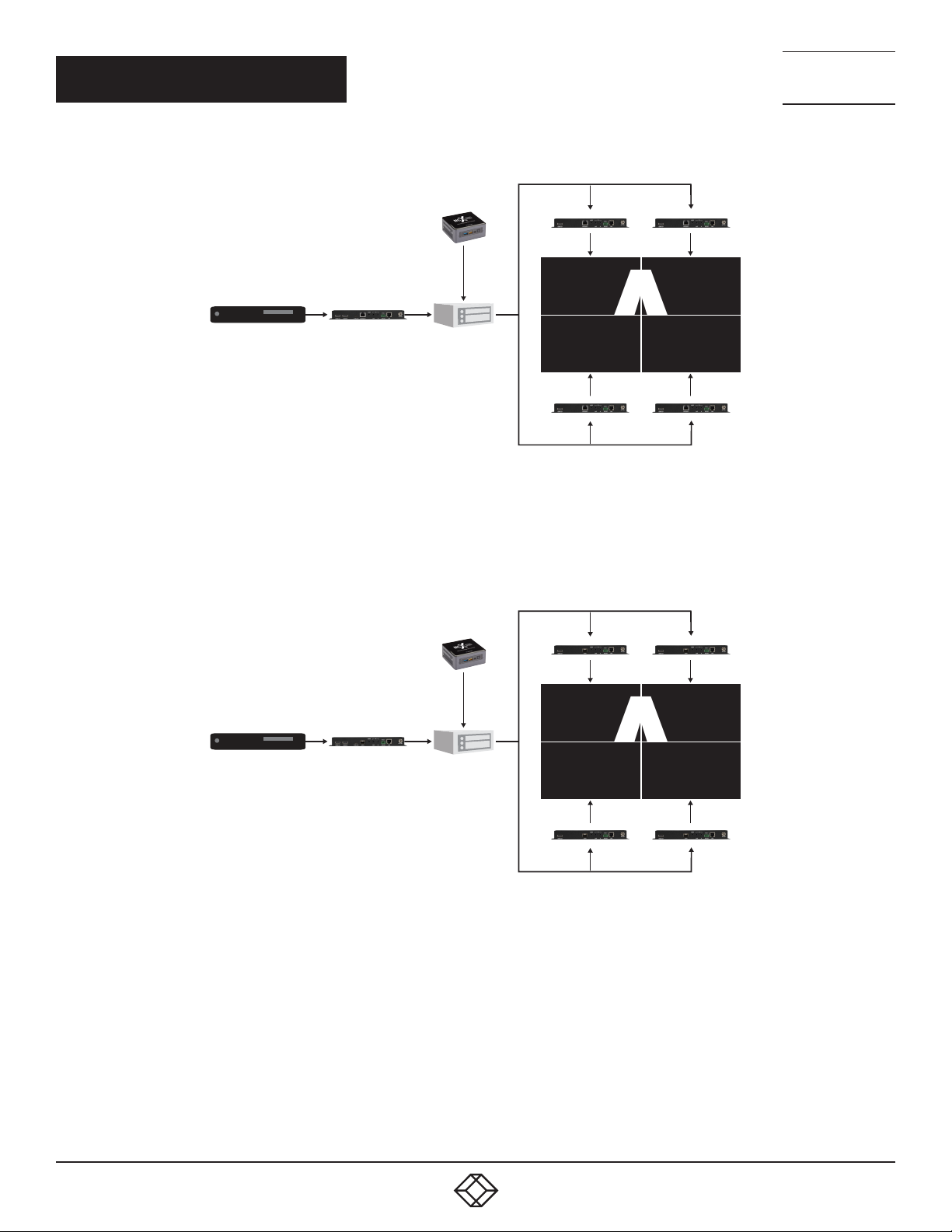
A
A
(2) Video Wall Conguration
10GbE Fiber
Network Switch
NEED HELP?
LEAV E TH E TEC H TO US
LIVE 24/7
TECHNICAL
SUPPORT
1. 8 7 7. 8 7 7. 2 2 6 9
FIGURE 2-23: COPPER VIDEO WALL CONFIGURATION
10GbE Fiber
Network Switch
FIGURE 2-24: FIBER VIDEO WALL CONFIGUR ATION
54
1. 87 7.8 7 7. 2 26 9 BLACKBOX.COM
Page 55
CHAPTER 2: DECODERS
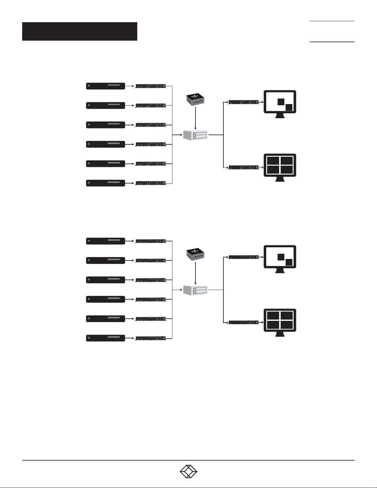
(3) Multiview (PiP/PoP/Quad/Etc.) Conguration
10GbE Fiber
Network Switch
1
3 4
5 6
NEED HELP?
LEAV E TH E TEC H TO US
LIVE 24/7
TECHNICAL
SUPPORT
1. 8 7 7. 8 7 7. 2 2 6 9
2
FIGURE 2-25: COPPER MULTIVIEW (PIP/POP/QUAD/ETC.) CONFIGURATION
10GbE Fiber
Network Switch
FIGURE 2-26: FIBER MULTIVIEW (PIP/POP/QUAD/ETC.) CONFIGURATION
1
2
3 4
5 6
1. 87 7.8 7 7. 2 26 9 BLACKBOX.COM
55
Page 56
CHAPTER 2: DECODERS
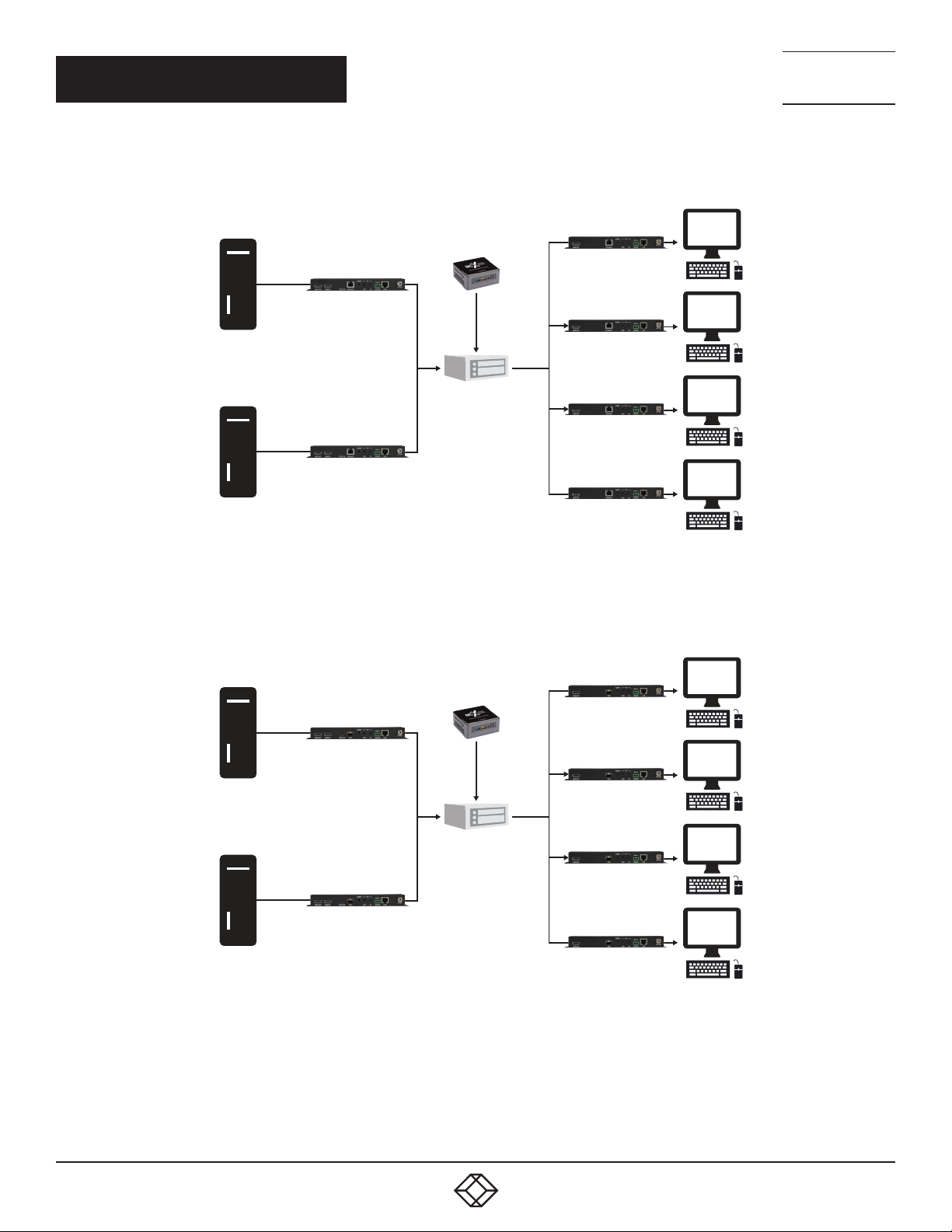
(4) KVM Switch Conguration
10GbE Fiber
Network Switch
NEED HELP?
LEAV E TH E TEC H TO US
LIVE 24/7
TECHNICAL
SUPPORT
1. 8 7 7. 8 7 7. 2 2 6 9
FIGURE 2-27: COPPER KVM SWITCH CONFIGURATION
10GbE Fiber
Network Switch
FIGURE 2-28: FIBER KVM SWITCH CONFIGUR ATION
56
1. 87 7.8 7 7. 2 26 9 BLACKBOX.COM
Page 57
CHAPTER 2: DECODERS
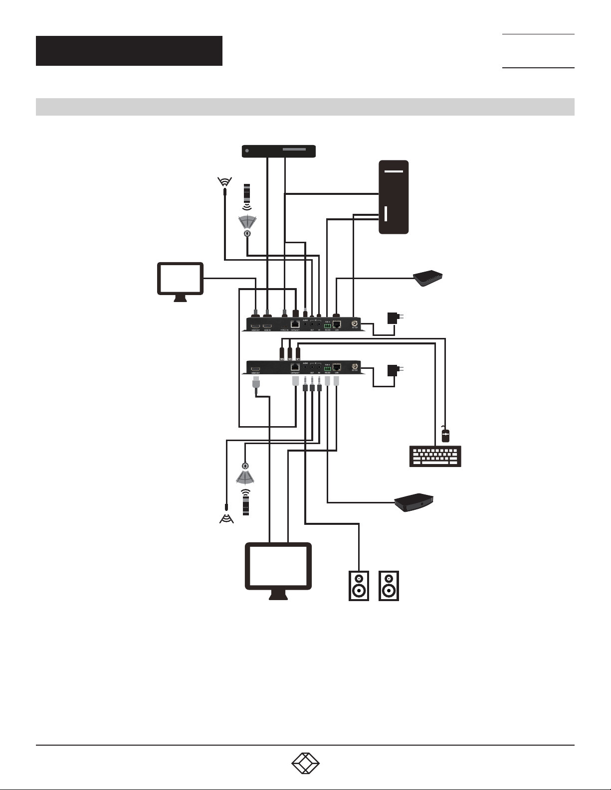
2.7 CONNECTION DIAGRAMS
Media Player
HDMI
Input
Stereo
Input
PC
NEED HELP?
LEAV E TH E TEC H TO US
LIVE 24/7
TECHNICAL
SUPPORT
1. 8 7 7. 8 7 7. 2 2 6 9
IR Input &
Output
Local Monitor
IR Input &
Output
HDMI
Output
Cat6A
Cable
HDMI
Output
Typ e C
Input
USB
RS-232
LAN
RS-232
Router
Power
Supply
Power
Supply
USB
Serial Controlled
LAN
Smart TV
FIGURE 2-29: COPPER CONNECTION DIAGRAM
1. 87 7.8 7 7. 2 26 9 BLACKBOX.COM
Stereo
Output
Powered Speakers
Device
57
Page 58
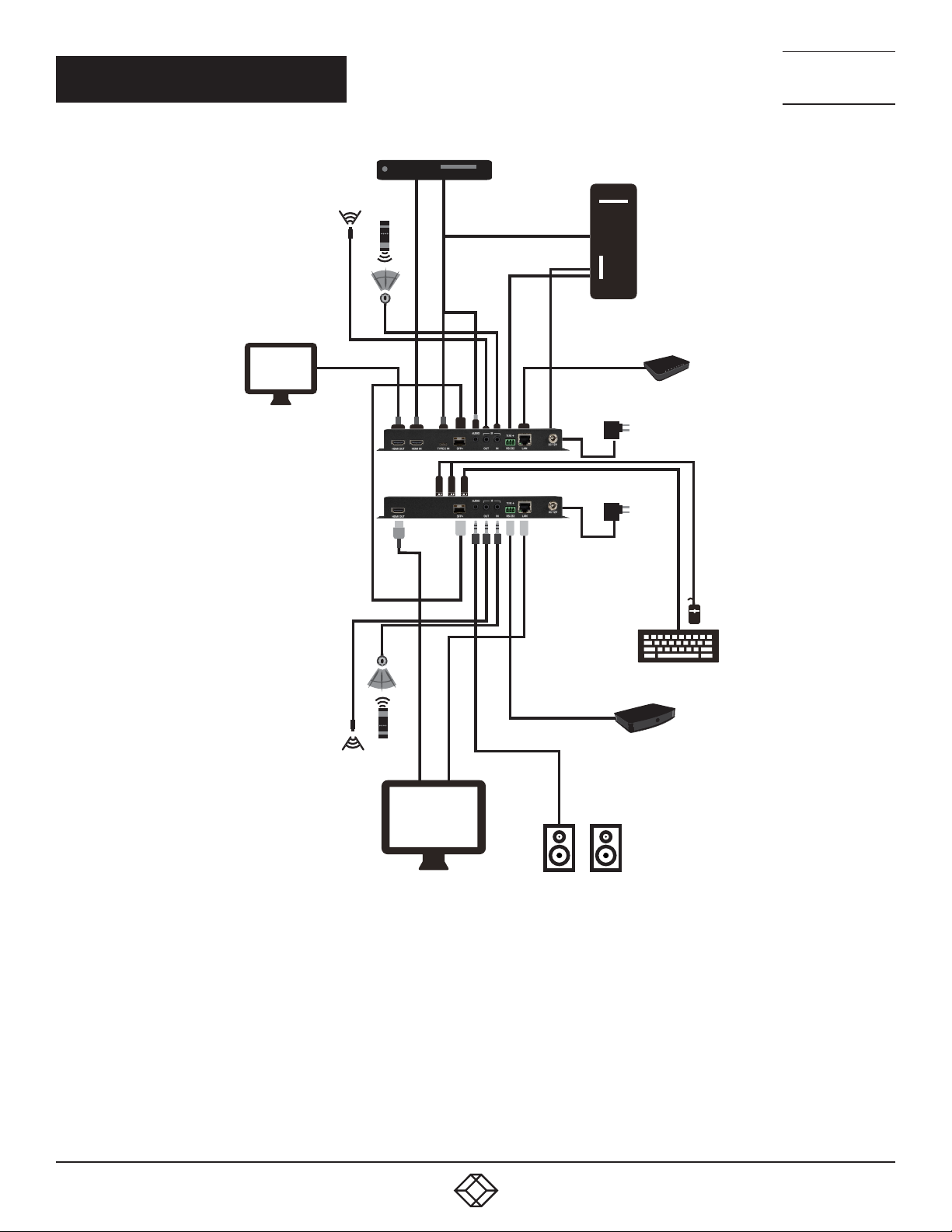
CHAPTER 2: DECODERS
Media Player
HDMI
Input
Stereo
Input
PC
NEED HELP?
LEAV E TH E TEC H TO US
LIVE 24/7
TECHNICAL
SUPPORT
1. 8 7 7. 8 7 7. 2 2 6 9
IR Input &
Output
Local Monitor
IR Input &
Output
HDMI
Output
Fiber
Cable
HDMI
Output
Typ e C
Input
USB
RS-232
LAN
RS-232
Router
Power
Supply
Power
Supply
USB
58
LAN
Smart TV
FIGURE 2-30: FIBER CONNECTION DIAGRAM
1. 87 7.8 7 7. 2 26 9 BLACKBOX.COM
Stereo
Output
Powered Speakers
Serial Controlled
Device
Page 59

CHAPTER 2: DECODERS
2.8. SPECIFICATIONS
TABLE 2-10. GENERAL SPECIFICATIONS
SPECIFICATION DESCRIPTION
HDMI Bandwidth 18 Gbps
10GbE Bandwidth 10 Gbps
Input Ports N/A
Output Ports (1) HDMI (Type A) female
Bi-Directional Port (1) Stereo Audio (3.5mm) female
(1) 10GbE LAN (RJ-45 for copper; SFP+ for fiber) female;
(1) IR (3.5mm) female;
Pass-Through Ports
IR Frequency 38kHz
Baud Rate 57600 (default), up to 115200 bps
Power Supply 12V/3A DC (US/EU standards, CE/FCC/UL certified)
ESD Protection (HBM)
Dimensions
Weight 916g
Chassis Metal Metal (steel)
Chassis Color Black
Operating Temperature 0 to 40˚C (32 to 104˚F)
Storage Temperature -20 to 60˚C (-4 to to 140˚F)
Relative Humidity 20 to 90% RH (Non-condensing)
Power Consumption 14.3w (for copper); 18.51w (for fiber)
(1) RS-232 (3-pin terminal block) female;
(1) LAN (RJ-45) female;
(3) USB 2.0 (Type A) female
±8kV (air discharge);
±4kV (contact discharge);
215mm x 25mm x 108mm (case only);
215mm x 25mm x 116.7 mm (all inclusive)
NEED HELP?
LEAV E TH E TEC H TO US
LIVE 24/7
TECHNICAL
SUPPORT
1. 8 7 7. 8 7 7. 2 2 6 9
1. 87 7.8 7 7. 2 26 9 BLACKBOX.COM
59
Page 60

CHAPTER 2: DECODERS
SUPPORTED RESOLUTIONS (HZ)
720×4 00p@70/85
640×480p@60/72/75/85
720×4 80i@60
720×4 80p@60
720×576i@50
720×576p@50
800×600p@56/60/72/75/85
848×480p@60
1024×76 8p@60/70/75/85
1152 ×864p@75
128 0×720p@50/60
128 0×768p@60/75/85
1280×800p@60/75/85
128 0×96 0p@60/85
128 0 ×1024 p@60/75/85
136 0×768 p@60
136 6×76 8p@60
14 00 ×1050p@60
1440× 900p@60/75
1600×900p@60RB
1600×1200p@60
16 8 0×10 50 p@60
19 2 0 ×108 0 i@50/60
19 2 0 ×108 0 p@24 /25/3 0
19 2 0 ×108 0 p@50/60
1920×1200p@60RB
25 60 ×144 0 p@60RB
2560×1600p@60RB
204 8 ×10⁸ 0 p@24 /25/3 0
204 8 ×10⁸ 0 p@50/60
38 40× 2160 p@24/25/30
38 40× 2160 p@5 0/6 0 (4:2:0)
38 40× 2160 p@24, HD R10
38 40× 2160 p@50/60 (4:2:0), HDR10
TABLE 2-11. VIDEO SPECIFICATIONS
INPUT OUTPUT
10GBE HDMI
NEED HELP?
LEAV E TH E TEC H TO US
LIVE 24/7
TECHNICAL
SUPPORT
1. 8 7 7. 8 7 7. 2 2 6 9
60
1. 87 7.8 7 7. 2 26 9 BLACKBOX.COM
Page 61
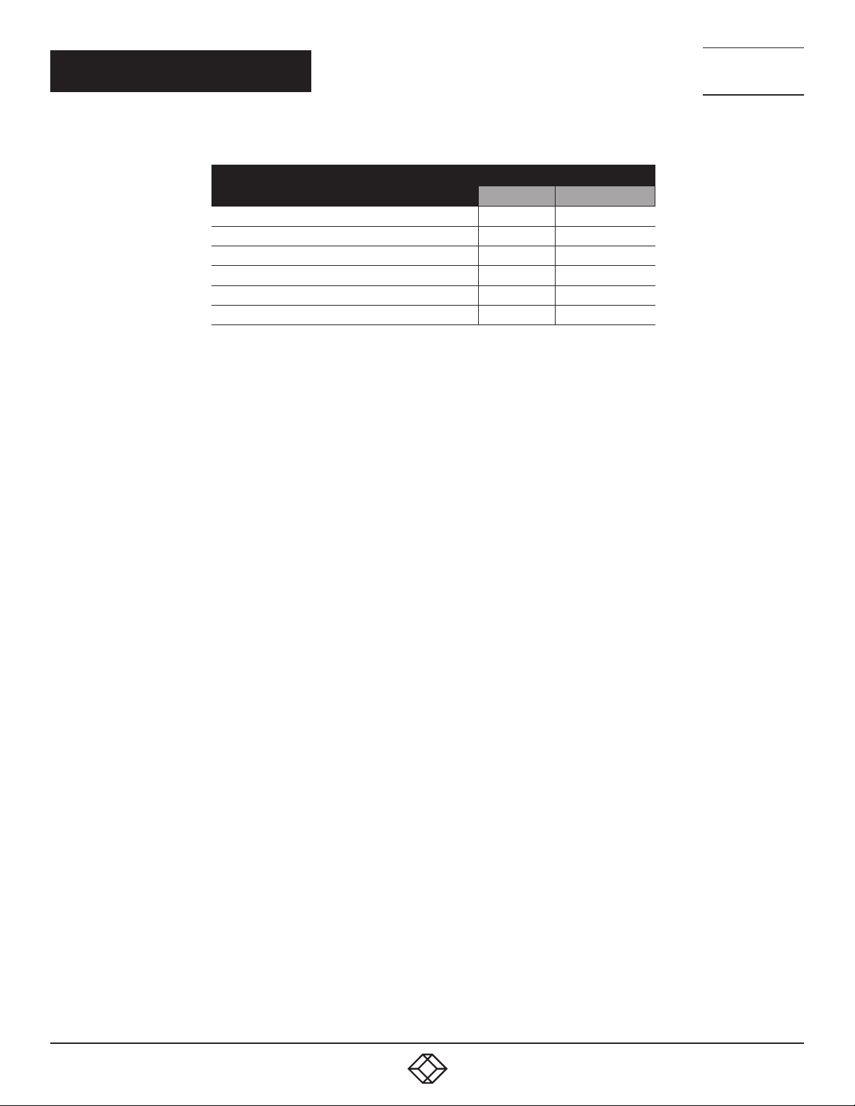
CHAPTER 2: DECODERS
TABLE 1-11. VIDEO SPECIFICATIONS CONTINUED
SUPPORTED RESOLUTIONS (HZ)
38 40× 2160 p@50/60
409 6×2160p@24/25/30
409 6×2160p@50/60 (4:2:0)
409 6×2160p@24, HDR10
409 6×2160p@50/60 (4:2:0), HDR10
409 6×2160p@50/60
TABLE 2-11. VIDEO SPECIFICATIONS
CONTINUED
INPUT OUTPUT
10GBE HDMI
NEED HELP?
LEAV E TH E TEC H TO US
LIVE 24/7
TECHNICAL
SUPPORT
1. 8 7 7. 8 7 7. 2 2 6 9
1. 87 7.8 7 7. 2 26 9 BLACKBOX.COM
61
Page 62

CHAPTER 2: DECODERS
TABLE 2-12. DIGITAL AUDIO HDMI OUTPUT SPECIFICATIONS
SPECIFICATION DESCRIPTION
LPCM
Max Channels 8 channels
Sampling Rate (kHz) 32, 44.1, 48
Bitstream
Supported Formats Standard and High Definition
TABLE 2-13. CAT5E/6/7 INPUT (COPPER)/FIBER INPUT (FIBER)
SPECIFICATION DESCRIPTION
LPCM
Max Channels 8 channels
Sampling Rate (kHz) 32, 44.1, 48
Bitstream
Supported Formats Standard and High Definition
NEED HELP?
LEAV E TH E TEC H TO US
LIVE 24/7
TECHNICAL
SUPPORT
1. 8 7 7. 8 7 7. 2 2 6 9
62
1. 87 7.8 7 7. 2 26 9 BLACKBOX.COM
Page 63

CHAPTER 2: DECODERS
TABLE 2-14. ANALOG AUDIO INPUT SPECIFICATIONS
SPECIFICATION DESCRIPTION
Max Audio Level 1Vrms
Impedance 10kΩ
Typ e Unbalanced
TABLE 2-15. ANALOG AUDIO OUPUT SPECIFICATIONS
SPECIFICATION DESCRIPTION
Max Audio Level 1Vrms
THD+N < −80dB@0dBFS 1kHz (A-wt)
SNR > 80dB@0dBFS
Frequency Response < ±1dB@20Hz~20kHz
Crosstalk < −80dB@10kHz
Impedance 470Ω
Typ e Unbalanced
NEED HELP?
LEAV E TH E TEC H TO US
LIVE 24/7
TECHNICAL
SUPPORT
1. 8 7 7. 8 7 7. 2 2 6 9
1. 87 7.8 7 7. 2 26 9 BLACKBOX.COM
63
Page 64
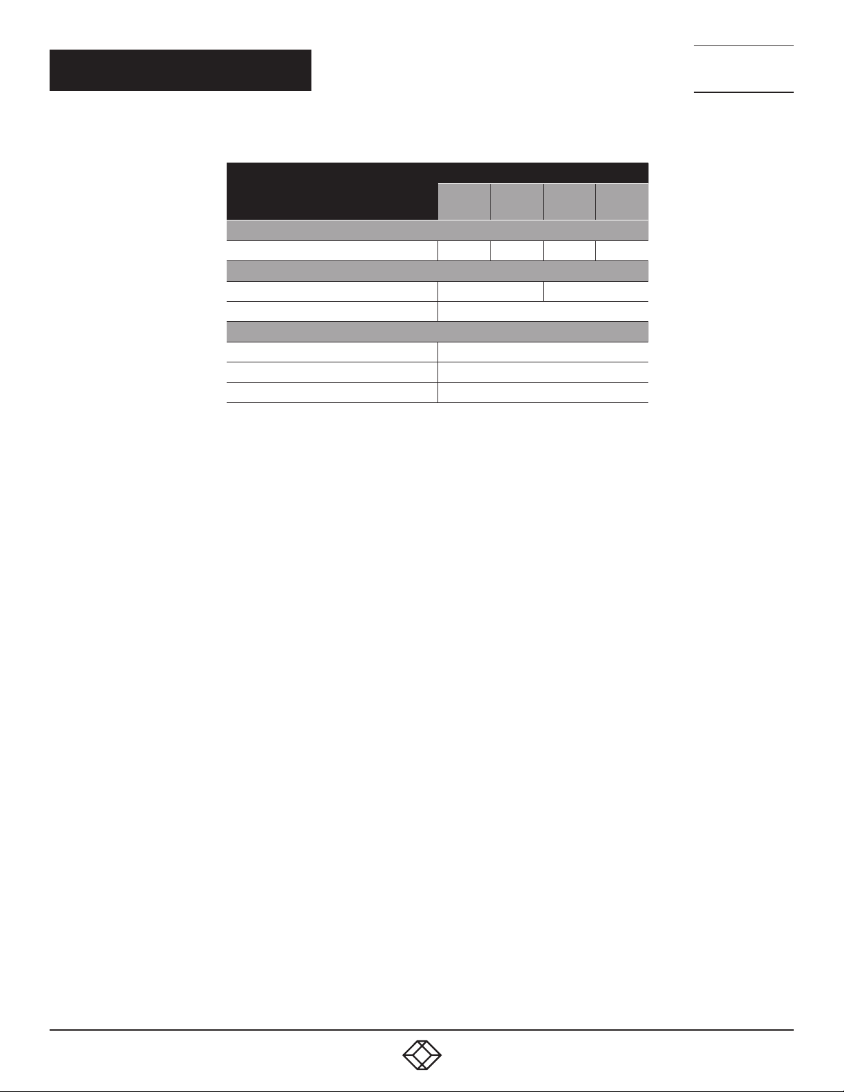
CHAPTER 2: DECODERS
CABLE LENGTH
HIGH SPEED HDMI CABLE
HDMI OUTPUT
CATEGORY CABLE (COPPER)
CAT. 5 E / 6 100m 70m
CAT. 6A /7 100m
FIBER CABLE
MULTI-MODE FIBER (OM3) 300m
MULTI-MODE FIBER (OM4) 550m
SINGLE-MODE FIBER 30km
TABLE 2-16. CABLE SPECIFICATIONS
1080P 4K30 4K60
8-BIT 12- BIT
15m 10m
(4:4:4)
8-BIT
5m
(4:4:4)
8-BIT
3m
NEED HELP?
LEAV E TH E TEC H TO US
LIVE 24/7
TECHNICAL
SUPPORT
1. 8 7 7. 8 7 7. 2 2 6 9
Bandwidth Category Examples:
1080p (FHD Video)
Up to 1080p@60Hz, 12-bit color
Data rates lower than 5.3Gbps or below 225MHz TMDS clock
4K30 (4K UHD Video)
4K@24/25/30Hz & 4K@50/60Hz (4:2:0), 8-bit color
Data rates higher than 5.3Gbps or above 225MHz TMDS clock but below 10.2Gbps
4K60 (4K UHD+ Video)
4K@50/60Hz (4:4:4, 8-bit)
4K@50/60Hz (4:2:0, 10-bit HDR)
Data rates higher than 10.2Gbps
64
1. 87 7.8 7 7. 2 26 9 BLACKBOX.COM
Page 65

APPENDIX A: ACRONYMS
A.1 ACRONYMS
ACRONYM COMPLETE TERM
10G B E 10 GIGABIT ETHERNET
ADC ANALOG-TO-DIGITAL CONVERTER
AVOIP AUDIO/VIDEO OVER IP
CAT.5 E ENHANCED CATEGORY 5 CABLE
CAT.6 CATEGORY 6 CABLE
CAT.6 A AUGMENTED CATEGORY 6 CABLE
CAT.7 CATEGORY 7 CABLE
DAC DIGITAL-TO-ANALOG CONVERTER
DB DECIBEL
DHCP DYNAMIC HOST CONFIGURATION PROTOCOL
DP DISPLAYPORT
DVI DIGITAL VISUAL INTERFACE
EDID EXTENDED DISPLAY IDENTIFICATION DATA
GBE GIGABIT ETHERNET
GBPS GIGABITS PER SECOND
GUI GRAPHICAL USER INTERFACE
HDCP HIGH-BANDWIDTH DIGITAL CONTENT PROTECTION
HDMI HIGH-DEFINITION MULTIMEDIA INTERFACE
HDR HIGH DYNAMIC RANGE
IEEE INSTITUTE OF ELECTRICAL AND ELECTRONICS ENGI-
IGMP INTERNET GROUP MANAGEMENT PROTOCOL
IP INTERNET PROTOCOL
IR INFRARED
KHZ KILOHERTZ
KVM KEYBOARD/VIDEO/MOUSE
LAN LOCAL AREA NETWORK
LED LIGHT-EMITTING DIODE
LPCM LINEAR PULSE-CODE MODULATION
MAC MEDIA ACCESS CONTROL
MHZ MEGAHERTZ
OSD ON-SCREEN DISPLAY
PIP PICTURE IN PICTURE
POP PICTURE OUTSIDE OF PICTURE
SDVOE SOFTWARE DEFINED VIDEO OVER ETHERNET
SNR SIGNAL-TO-NOISE RATIO
TCP TRANSMISSION CONTROL PROTOCOL
THD+N TOTAL HARMONIC DISTORTION PLUS NOISE
TMDS TRANSITION-MINIMIZED DIFFERENTIAL SIGNALING
4K UHD 4K ULTRA-HIGH-DEFINITION (10.2GBPS MAX)
+
4K UHD
TABLE A-1 ACRONYMS
NEERS
4K ULTRA-HIGH-DEFINITION (18GBPS MAX)
NEED HELP?
LEAV E TH E TEC H TO US
LIVE 24/7
TECHNICAL
SUPPORT
1. 8 7 7. 8 7 7. 2 2 6 9
1. 87 7.8 7 7. 2 26 9 BLACKBOX.COM
65
Page 66

APPENDIX A: ACRONYMS
NEED HELP?
LEAV E TH E TEC H TO US
LIVE 24/7
TECHNICAL
SUPPORT
1. 8 7 7. 8 7 7. 2 2 6 9
TABLE A-1 ACRONYMS CONTINUED
TABLE A-1 ACRONYMS
ACRONYM COMPLETE TERM
USB UNIVERSAL SERIAL BUS
VGA VIDEO GRAPHICS ARRAY
VOIP VIDEO OVER IP
WUXGA (RB) WIDESCREEN ULTRA EXTENDED GRAPHICS ARRAY (RE-
DUCED BLANKING)
XGA EXTENDED GR APHICS ARR AY
Ω OHM
66
1. 87 7.8 7 7. 2 26 9 BLACKBOX.COM
Page 67

NEED HELP?
LEAV E TH E TEC H TO US
LIVE 24/7
CHAPTER 1: HEADLINE
APPENDIX B: REGULATORY INFORMATION
TECHNICAL
SUPPORT
1. 8 7 7. 8 7 7. 2 2 6 9
B.1 FCC STATEMENT
This equipment has been tested and found to comply with the regulations for a Class B digital device, pursuant to Part 15 of
the FCC Rules. These limits are designed to provide reasonable protection against harmful interference when the equipment
is operated in a commercial environment. This equipment generates, uses, and can radiate radio frequency energy and, if not
installed and used in accordance with this Quick Installation Guide, may cause harmful interference to radio communications.
Operation of this equipment in a residential area is likely to cause harmful interference in which case, the user will be required to
correct the interference at his/her own expense.
B.2 CE STATEMENT
This is a Class B product in a domestic environment, this product may cause radio interference, in which case the user may be
required to take adequate measures.
B.3 ROHS
This product is RoHS compliant.A.4 NOM Statement
67
1. 87 7.8 7 7. 2 26 9 BLACKBOX.COM
1. 87 7.8 7 7. 2 26 9 BLACKBOX.COM
67
Page 68

NEED HELP?
LEAV E TH E TEC H TO US
LIVE 24/7
CHAPTER 1: HEADLINE
APPENDIX B: REGULATORY INFORMATION
TECHNICAL
SUPPORT
1. 8 7 7. 8 7 7. 2 2 6 9
B.4 NOM STATEMENT
1. Todas las instrucciones de seguridad y operación deberán ser leídas antes de que el aparato eléctrico sea operado.
2. Las instrucciones de seguridad y operación deberán ser guardadas para referencia futura.
3. Todas las advertencias en el aparato eléctrico y en sus instrucciones de operación deben ser respetadas.
4. Todas las instrucciones de operación y uso deben ser seguidas.
5. El aparato eléctrico no deberá ser usado cerca del agua—por ejemplo, cerca de la tina de baño, lavabo, sótano mojado o cerca
de una alberca, etc.
6. El aparato eléctrico debe ser usado únicamente con carritos o pedestales que sean recomendados por el fabricante.
7. El aparato eléctrico debe ser montado a la pared o al techo sólo como sea recomendado por el fabricante.
8. Servicio—El usuario no debe intentar dar servicio al equipo eléctrico más allá a lo descrito en las instrucciones de operación.
Todo otro servicio deberá ser referido a personal de servicio calificado.
9. El aparato eléctrico debe ser situado de tal manera que su posición no interfiera su uso. La colocación del aparato eléctrico
sobre una cama, sofá, alfombra o superficie similar puede bloquea la ventilación, no se debe colocar en libreros o gabinetes que
impidan el flujo de aire por los orificios de ventilación.
10. El equipo eléctrico deber ser situado fuera del alcance de fuentes de calor como radiadores, registros de calor, estufas u otros
aparatos (incluyendo amplificadores) que producen calor.
11. El aparato eléctrico deberá ser connectado a una fuente de poder sólo del tipo descrito en el instructivo de operación, o como
se indique en el aparato.
12. Precaución debe ser tomada de tal manera que la tierra fisica y la polarización del equipo no sea eliminada.
13. Los cables de la fuente de poder deben ser guiados de tal manera que no sean pisados ni pellizcados por objetos colocados
sobre o contra ellos, poniendo particular atención a los contactos y receptáculos donde salen del aparato.
14. El equipo eléctrico debe ser limpiado únicamente de acuerdo a las recomendaciones del fabricante.
15. En caso de existir, una antena externa deberá ser localizada lejos de las lineas de energia.
16. El cable de corriente deberá ser desconectado del cuando el equipo no sea usado por un largo periodo de tiempo.
17. Cuidado debe ser tomado de tal manera que objectos liquidos no sean derramados sobre la cubierta u orificios de ventilación.
18. Servicio por personal calificado deberá ser provisto cuando:
A: El cable de poder o el contacto ha sido dañado; u
B: Objectos han caído o líquido ha sido derramado dentro del aparato;o
C: El aparato ha sido expuesto a la lluvia; o
D: El aparato parece no operar normalmente o muestra un cambio en su desempeño; o
E: El aparato ha sido tirado o su cubierta ha sido dañada.
68
1. 87 7.8 7 7. 2 26 9 BLACKBOX.COM
1. 87 7.8 7 7. 2 26 9 BLACKBOX.COM
68
Page 69

NEED HELP?
LEAV E TH E TEC H TO US
LIVE 24/7
CHAPTER 1: HEADLINE
APPENDIX C: DISCLAIMER/TRADEMARKS
TECHNICAL
SUPPORT
1. 8 7 7. 8 7 7. 2 2 6 9
C.1 DISCLAIMER
Black Box Corporation shall not be liable for damages of any kind, including, but not limited to, punitive, consequential or cost of cover
damages, resulting from any errors in the product information or specifications set forth in this document and Black Box Corporation
may revise this document at any time without notice.
C.2 TRADEMARKS USED IN THIS MANUAL
Black Box and the Black Box logo type and mark are registered trademarks of Black Box Corporation.
Any other trademarks mentioned in this manual are acknowledged to be the property of the trademark owners.
1. 87 7.8 7 7. 2 26 9 BLACKBOX.COM
69
Page 70

NEED HELP?
LEAVE THE TECH TO US
LIVE 24/7
TECHNICAL
SUPPORT
1.87 7. 87 7. 2 26 9
© COPYRIGHT 2021. BLACK BOX CORPORATION. ALL RIGHTS RESERVED.
MCX_G2-USER_REV1.PDF
 Loading...