

Black Box MCX-G2-CONTROL-24, MCX-G2-CONTROL-48, MCX-G2-CONTROL-120, MCX-G2-CONTROL-250, MCX-G2-CONTROL-500 User guide
...Page 1
USER MANUAL
MCX-G2-CONTROL-24, -48, -120, -250, -500, -UL
MCX NETWORK
MANAGEMENT
CONTROLLER
24/7 TECHNICAL SUPPORT AT 1.877.877.2269 OR VISIT BLACKBOX.COM
SS
Page 2

NEED HELP?
LEAV E TH E TEC H TO US
LIVE 24/7
TABLE OF CONTENTS
TECHNICAL
SUPPORT
1. 8 7 7. 8 7 7. 2 2 69
CONTENTS
1. GLOBAL SETTINGS ...................................................................................................................................................................................... 6
1.1 U S ERS ........................................................................................................................................................................................................... 6
1.1.1 A DD U S ER ............................................................................................................................................................................................................... 6
1.1.2 E D IT US E R .............................................................................................................................................................................................................. 8
1.1.3 DELETE USER ........................................................................................................................................................................................................ 9
1.1.4 AC T I VE US E R S ....................................................................................................................................................................................................10
1.2 PRES E TS ................................................................................................................................................................................................... 10
1.2.1 NEW PRESET.......................................................................................................................................................................................................10
1.2.2 EDIT PRESET ......................................................................................................................................................................................................12
1.2.3 DELETE PRESET ................................................................................................................................................................................................ 13
1.2.4 APPLY PRESET ...................................................................................................................................................................................................14
1.2.5 EXPORT PRESET ............................................................................................................................................................................................... 15
1.2.6 IMPORT PRESET ............................................................................................................................................................................................... 16
1.2.7 PRESET RECORD ...............................................................................................................................................................................................17
1.3 GROU P S ..................................................................................................................................................................................................... 18
1.3.1 A DD G RO U P ......................................................................................................................................................................................................... 18
1.3.2 EDIT GROUP ........................................................................................................................................................................................................19
1.3.3 DELETE GROUP ................................................................................................................................................................................................. 20
1.4 MULT I C A S T ............................................................................................................................................................................................... 20
1.4.1 MULTICAST AUTO ............................................................................................................................................................................................ 20
1.4.2 MULTICAST MANUAL ..................................................................................................................................................................................... 22
1.5 SECURITY KEYS ....................................................................................................................................................................................... 22
1.5.1 HTTP API SECURIT Y KEY ............................................................................................................................................................................... 22
1.5.2 TCP SECURIT Y KEY ......................................................................................................................................................................................... 24
1.6 ANALYTICS ............................................................................................................................................................................................... 25
1.6.1 SOURCE AVAILABILIT Y ....................................................................................................................................................................................25
1.6.2 DISPLAY AVAILABILITY ...................................................................................................................................................................................26
1.6.3 SOURCE RESOLUTION .................................................................................................................................................................................... 27
1.6.4 SOURCE COUNT ................................................................................................................................................................................................ 28
1.6.5 DISPL AY C O U NT ............................................................................................................................................................................................... 29
1.6.6 DISPLAY SOURCE CHANGE ........................................................................................................................................................................... 30
1.6.7 NETWORK DOWNTIME ....................................................................................................................................................................................31
1.6.8 TEMPERATURE ................................................................................................................................................................................................. 32
1.6.9 B A NDWIDTH ....................................................................................................................................................................................................... 33
1.7 SCHEDULER .............................................................................................................................................................................................. 34
1.8 PERMISSIONS .......................................................................................................................................................................................... 35
1.9 ENCRYPTION ............................................................................................................................................................................................ 36
1.10 NOTIFICATIONS...................................................................................................................................................................................... 37
1.10.1 EMAIL SETTINGS ............................................................................................................................................................................................ 38
2
1. 8 77. 8 7 7. 2 2 69 BLACKBOX.COM
Page 3

NEED HELP?
LEAV E TH E TEC H TO US
LIVE 24/7
TABLE OF CONTENTS
TECHNICAL
SUPPORT
1. 8 7 7. 8 7 7. 2 2 69
2. DEVICE SETTINGS ..................................................................................................................................................................................... 39
2.1 EDIT SETTINGS ........................................................................................................................................................................................ 39
2.1.1 N AME .................................................................................................................................................................................................................... 39
2.1.2 GROUPS ............................................................................................................................................................................................................... 40
2.1.3 NETWORK INTERFACE ..................................................................................................................................................................................... 42
2.1.4 HDMI/DP INTERFACE ...................................................................................................................................................................................... 44
2.1.5 HDMI INTERFACE (DECODER) ....................................................................................................................................................................... 45
2.1.6 MULTICAST MANAGEMENT .......................................................................................................................................................................... 46
2.1.7 ANALOG AUDIO INTERFACE ...........................................................................................................................................................................47
2.1.8 ANALOG AUDIO JACK .......................................................................................................................................................................................47
2.1.9 HDMI AUDIO SOURCE ...................................................................................................................................................................................... 48
2.1.10 RS-232 SERIAL INTERFACE PARAMETERS .............................................................................................................................................. 48
2.2 EXPORT SETTINGS ................................................................................................................................................................................. 49
2.3 IMPORT SETTINGS ................................................................................................................................................................................50
3. S TATUS ........................................................................................................................................................................................................ 51
3.1 IDENTIFY ................................................................................................................................................................................................... 51
3.2.1 STREAMS (ENCODER) ..................................................................................................................................................................................... 52
3.2.2 STREAMS (DECODER) ..................................................................................................................................................................................... 52
3.2.3 SUBSCRIPTIONS (DECODER) ........................................................................................................................................................................ 53
3.2.4 ADVANCED ......................................................................................................................................................................................................... 54
3.3 EXPORT ..................................................................................................................................................................................................... 54
3.4 EXPORT STATUS REPORT ......................................................................................................................................................................55
3.5 GROUP HEALTH ....................................................................................................................................................................................... 56
4. TOOLS .......................................................................................................................................................................................................... 57
4.1 SEND SERIAL ............................................................................................................................................................................................ 57
4.2 SEND INFRARED ...................................................................................................................................................................................... 58
4.3 SEND CONTROL COMMAND.................................................................................................................................................................. 59
4.4 REBOOT DE VICE ...................................................................................................................................................................................... 59
4.6 RES E T D E VICE .......................................................................................................................................................................................... 60
4.6 UPDATE DEVICE FIRMWARE ..................................................................................................................................................................61
4.6.1 UPDATE MCX FIRMWARE ................................................................................................................................................................................61
4.7 USB DISCOVERY.......................................................................................................................................................................................61
5. M ATRIX ........................................................................................................................................................................................................ 63
5.1 VIDEO/DIGITAL AUDIO ............................................................................................................................................................................ 63
5.2 VIDEO ......................................................................................................................................................................................................... 63
5.3 DIGITAL AUDIO ......................................................................................................................................................................................... 64
5.4 ANALOG AUDIO ........................................................................................................................................................................................ 65
5.5 SERIAL ....................................................................................................................................................................................................... 65
5.6 INFRARED ................................................................................................................................................................................................. 66
5.7 U S B ............................................................................................................................................................................................................. 66
1. 8 77. 8 7 7. 2 2 69 BLACKBOX.COM
3
Page 4

NEED HELP?
LEAV E TH E TEC H TO US
LIVE 24/7
TABLE OF CONTENTS
6. VIDEO WALL ................................................................................................................................................................................................ 67
6.1 VIDEO WALL STANDARD ........................................................................................................................................................................68
6.2 VIDEO WALL ADVANCED ........................................................................................................................................................................ 70
7. M U LT I VI EW ................................................................................................................................................................................................. 73
7.1 MULTIVIEW LAYOUT ................................................................................................................................................................................ 74
7.2 MULTIVIEW LIVE ...................................................................................................................................................................................... 75
7.3 MULTIVIEW LAYOUT IMPORT................................................................................................................................................................75
7.4 MULTIVIEW PRESETS ............................................................................................................................................................................. 76
8. SYSTEM SETTINGS ................................................................................................................................................................................... 80
8.1 NETWORK SETTINGS .............................................................................................................................................................................. 80
8.2 ADVANCED SETTINGS ............................................................................................................................................................................81
8.2.1 DEVICE DATA REFRESH ...................................................................................................................................................................................81
8.2.2 USB DATA REFRESH .........................................................................................................................................................................................81
8.2.3 LEAVE SUBSCRIPTIONS ON STOP ...............................................................................................................................................................81
8.2.4 LEAVE SUBSCRIPTIONS ON SYSTEM START............................................................................................................................................81
8.2.5 TEMPERATURE ................................................................................................................................................................................................. 82
8.2.6 CONNECTIONS LIMIT ..................................................................................................................................................................................... 82
8.3 EXPORT SETTINGS ............................................................................................................................................................................................. 82
8.4 IMPORT SETTINGS .................................................................................................................................................................................83
8.5 SYSTEM CLOCK .......................................................................................................................................................................................83
8.6 SYSTEM REBOOT ..................................................................................................................................................................................... 84
8.7 SYSTEM LOGS .......................................................................................................................................................................................... 84
8.7.1 M C X L OG .............................................................................................................................................................................................................. 84
8.7.2 SYSTEM LOG ...................................................................................................................................................................................................... 85
8.7.3 USB LOG .............................................................................................................................................................................................................. 85
8.8 CHECK FOR UPDATES ............................................................................................................................................................................. 86
8.9 IMPORT UPDATES ................................................................................................................................................................................... 87
8.10 L I CEN SE ................................................................................................................................................................................................... 88
8.11 V E RS ION .................................................................................................................................................................................................. 88
9. UI OVERVIEW .............................................................................................................................................................................................. 89
TECHNICAL
SUPPORT
1. 8 7 7. 8 7 7. 2 2 69
4
1. 8 77. 8 7 7. 2 2 69 BLACKBOX.COM
Page 5

NEED HELP?
LEAV E TH E TEC H TO US
LIVE 24/7
TABLE OF CONTENTS
TECHNICAL
SUPPORT
1. 8 7 7. 8 7 7. 2 2 69
APPENDIX A. HOW TO VIDEO WALL WITH MULTIVIEW .......................................................................................................................... 91
APPENDIX B. SECURITY FEATURES ........................................................................................................................................................... 93
APPENDIX C. MULTICAST MANAGEMENT ...............................................................................................................................................95
APPENDIX D. USING GOOGLE ASSISTANT ............................................................................................................................................... 96
APPENDIX E. FREQUENTLY-ASKED QUESTIONS (FAQS) ........................................................................................................................ 97
F.1 DISCLAIMER ............................................................................................................................................................................. 100
F.2 TRADEMARKS USED IN THIS MANUAL ...................................................................................................... .......................... 100
1. 8 77. 8 7 7. 2 2 69 BLACKBOX.COM
5
Page 6
CHAPTER 1: GLOBAL SETTINGS
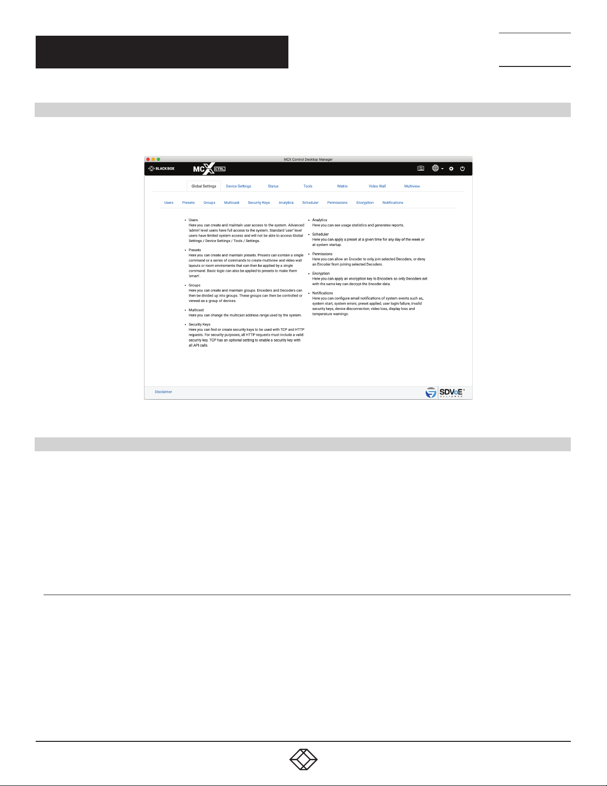
1. GLOBAL SETTINGS
Here you will find all the global settings of the software.
NEED HELP?
LEAV E TH E TEC H TO US
LIVE 24/7
TECHNICAL
SUPPORT
1. 8 7 7. 8 7 7. 2 2 69
FIGURE 1-1.
1.1 U S ER S
The system can be configured for user access control. Two levels of access are available, administrator and user. An administrator will
have complete access, while a user is limited to the following areas:
Status
Matrix
Video Wall
Multiview
The device groups for a user can also be limited so that only selected groups of Encoders and Decoders may be accessed.
1.1.1 A DD U S ER
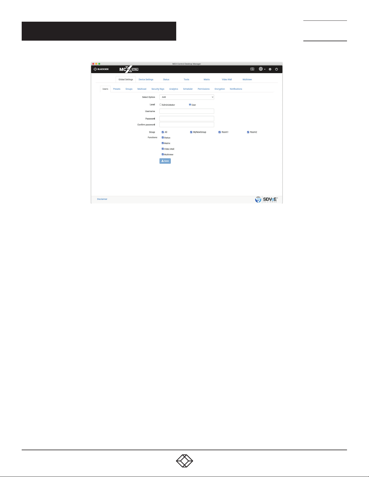
Here you can add a user to the system by selecting Administrator or User access level, then enter a name and password for the new user.
For user level access, you can also select the accessible groups and functions.
6
1. 8 77. 8 7 7. 2 2 69 BLACKBOX.COM
Page 7
CHAPTER 1: GLOBAL SETTINGS
NEED HELP?
LEAV E TH E TEC H TO US
LIVE 24/7
TECHNICAL
SUPPORT
1. 8 7 7. 8 7 7. 2 2 69
1. Select Add
2. Select Level
3. Enter Username
4. Enter Password
5. Confirm Password
6. Select Groups
7. Select Functions
8. Click Save button
FIGURE 1-2.
1. 8 77. 8 7 7. 2 2 69 BLACKBOX.COM
7
Page 8
CHAPTER 1: GLOBAL SETTINGS
1.1.2 E D IT US E R
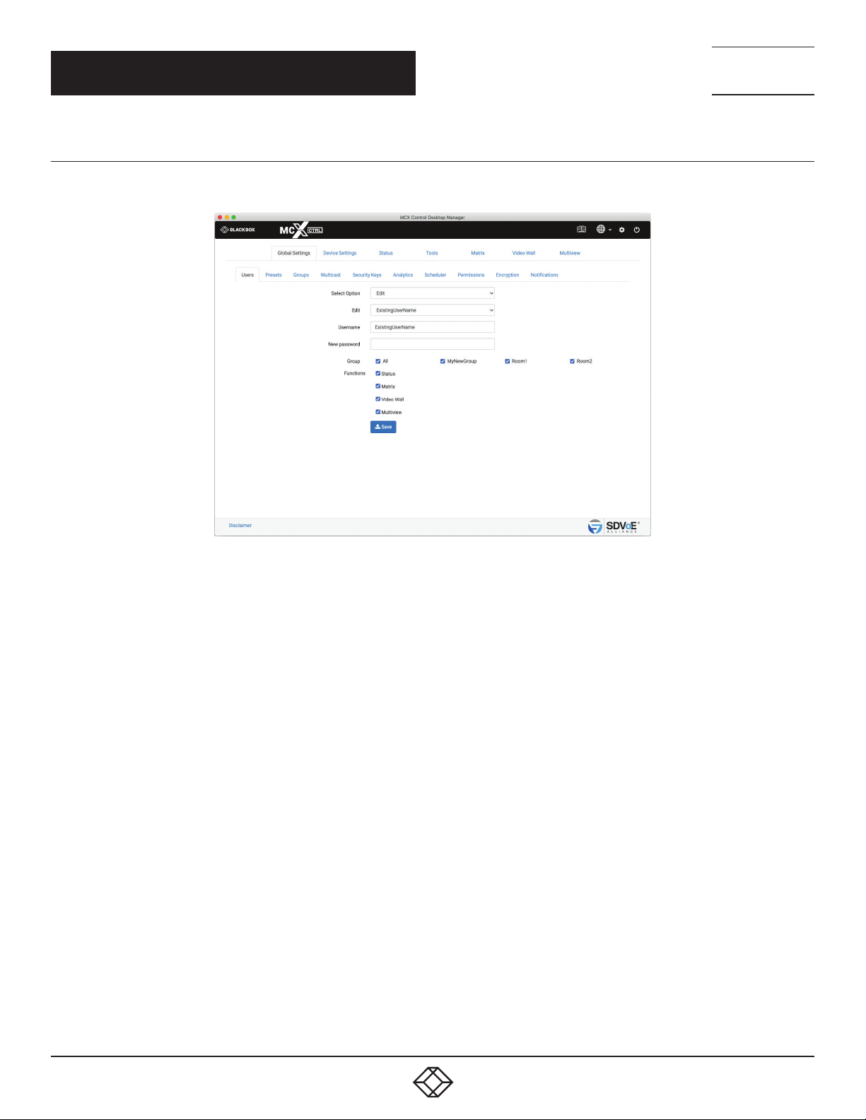
Here you can edit an existing users Username, Password, allocated groups, and functions.
NEED HELP?
LEAV E TH E TEC H TO US
LIVE 24/7
TECHNICAL
SUPPORT
1. 8 7 7. 8 7 7. 2 2 69
1. Select Edit
2. Select User
3*. Change Username
4. Enter new Password
5. Select Groups
6. Select Functions
7. Click Save button
FIGURE 1-3.
8
1. 8 77. 8 7 7. 2 2 69 BLACKBOX.COM
Page 9
CHAPTER 1: GLOBAL SETTINGS
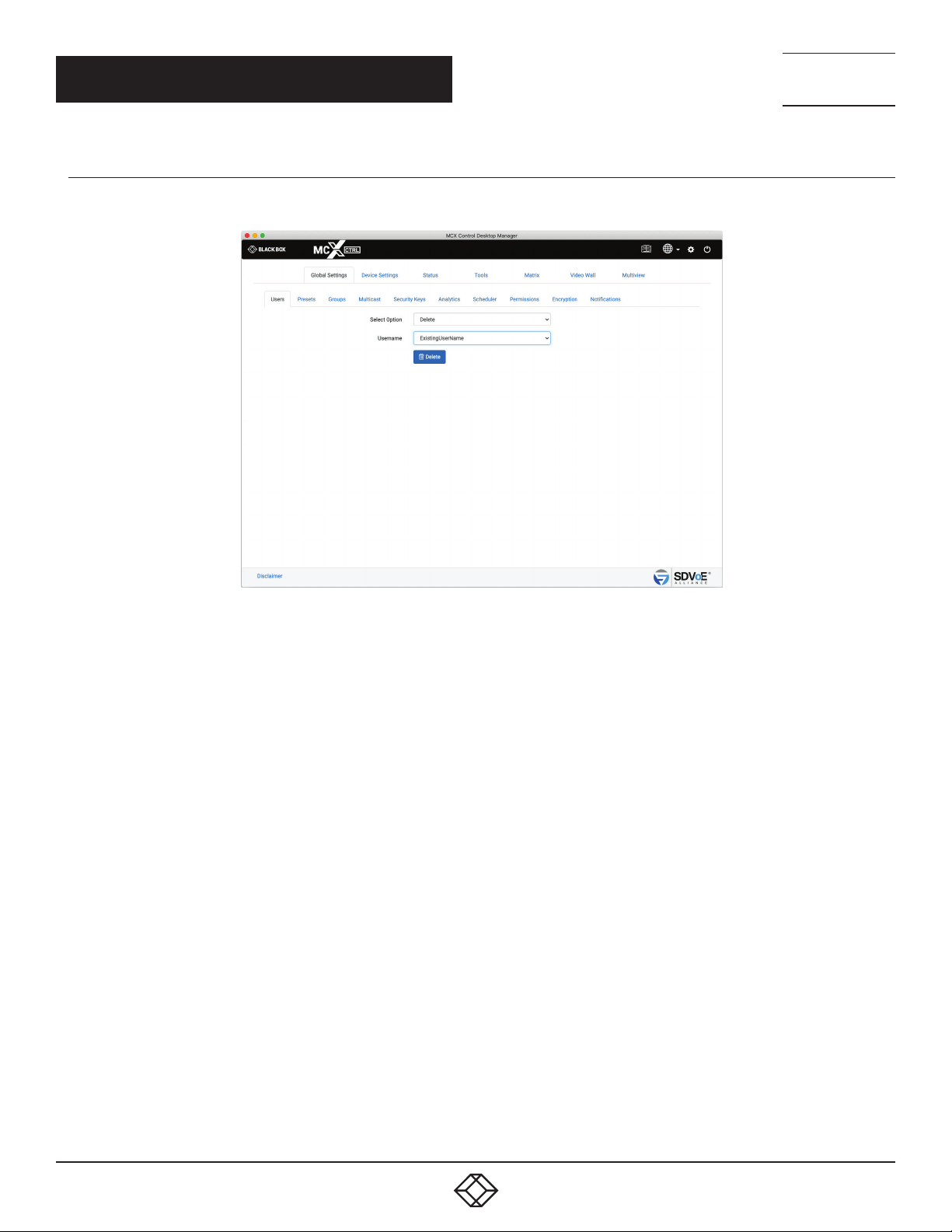
1.1.3 DELETE USER
Here you can delete an existing user from the system.
NEED HELP?
LEAV E TH E TEC H TO US
LIVE 24/7
TECHNICAL
SUPPORT
1. 8 7 7. 8 7 7. 2 2 69
1. Select Delete
2. Select User
3. Click Delete button
FIGURE 1-4.
1. 8 77. 8 7 7. 2 2 69 BLACKBOX.COM
9
Page 10
CHAPTER 1: GLOBAL SETTINGS
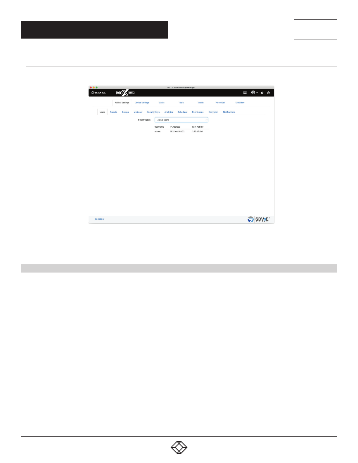
1.1.4 AC T I VE US E R S
Here you can see all the active users logged into the system and the time of their last activity.
NEED HELP?
LEAV E TH E TEC H TO US
LIVE 24/7
TECHNICAL
SUPPORT
1. 8 7 7. 8 7 7. 2 2 69
FIGURE 1-5.
1. Select Active Users
1.2 PRESETS
The system can store a virtually unlimited number of presets. A preset can be applied with a single “preset load” command. The preset
can contain a virtually unlimited number of commands.
Presets can contain anything from a single command to a multiview or video wall layout.
Presets can also contain basic if else logic to allow you to build some “smarts” into your system. Refer to Appendix E – Preset Logic in
the command manual for further details.
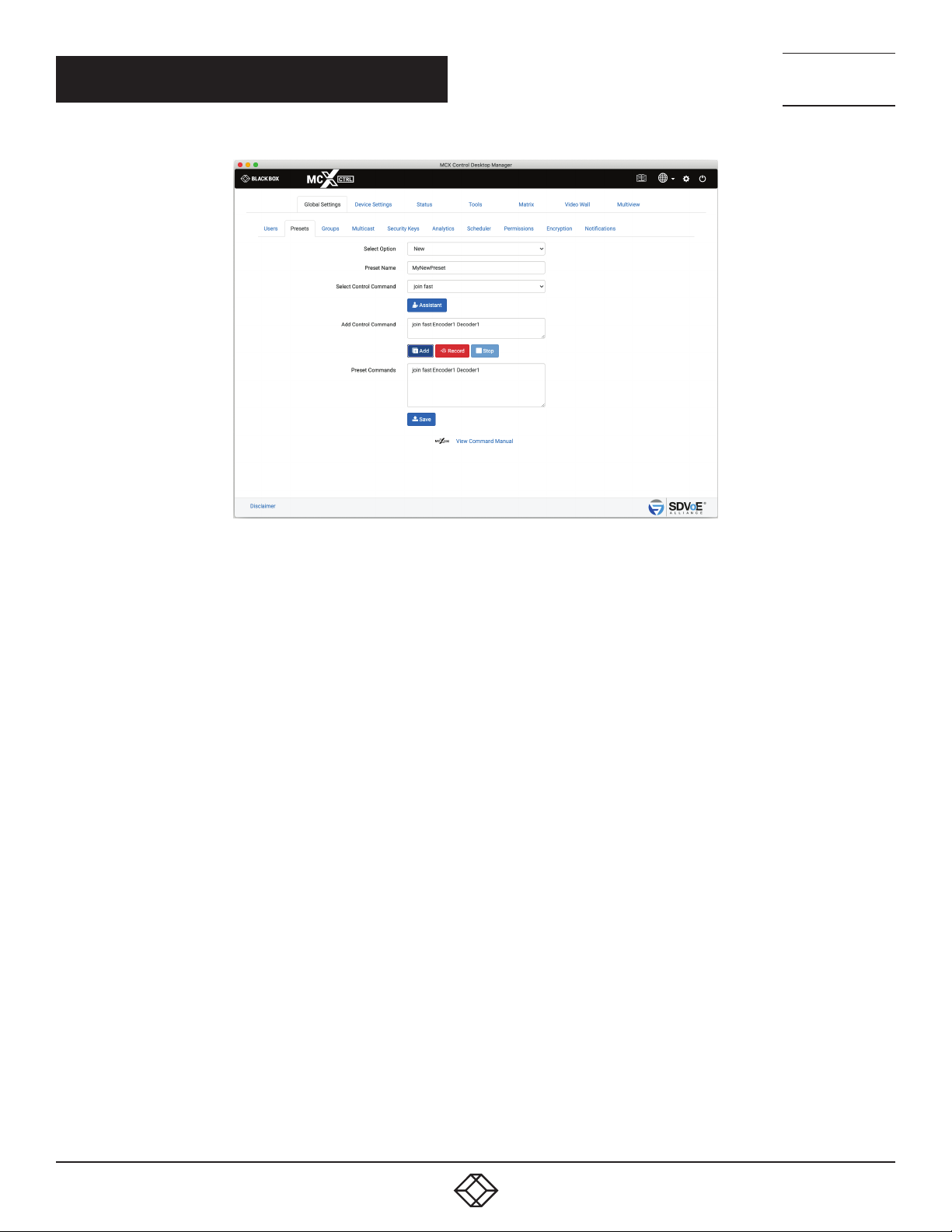
1.2.1 NEW PRESET
Here you can create a new preset to be stored on the system. Give the preset a name and then start adding control commands as
required by either entering commands directly, using the Assistant or Record function which will record interactions from the UI.
10
1. 8 77. 8 7 7. 2 2 69 BLACKBOX.COM
Page 11
CHAPTER 1: GLOBAL SETTINGS
NEED HELP?
LEAV E TH E TEC H TO US
LIVE 24/7
TECHNICAL
SUPPORT
1. 8 7 7. 8 7 7. 2 2 69
FIGURE 1-6.
1. Select New.
2. Enter a name.
3. Select a command or click Record button.
4. Fill in the required data or use the Assistant or click Stop if recording.
5. Click Add button.
6. Click Save button.
1. 8 77. 8 7 7. 2 2 69 BLACKBOX.COM
11
Page 12
CHAPTER 1: GLOBAL SETTINGS
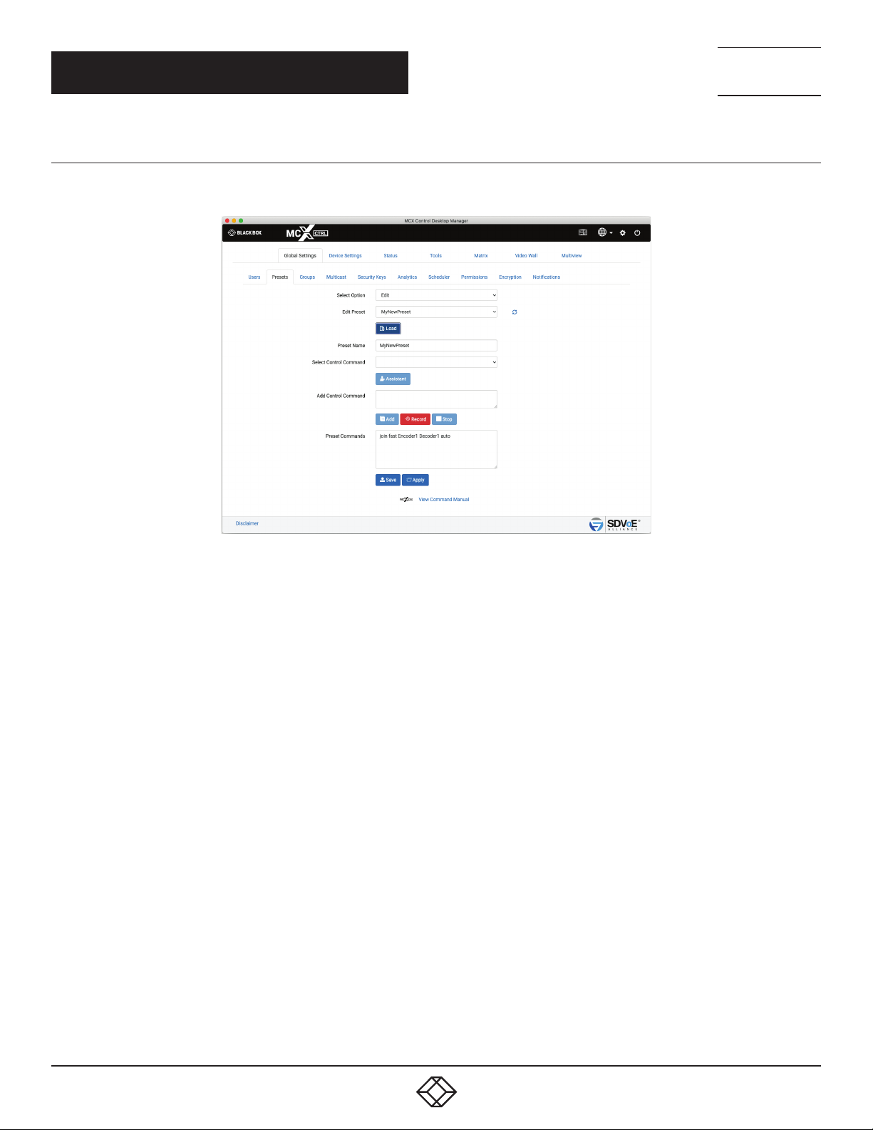
1.2.2 EDIT PRESET
Here you can edit any existing preset by adding, deleting or changing control commands as required.
NEED HELP?
LEAV E TH E TEC H TO US
LIVE 24/7
TECHNICAL
SUPPORT
1. 8 7 7. 8 7 7. 2 2 69
FIGURE 1-7.
1. Select Edit
2. Select Preset
3. Click Load button
4. Change preset name
5. Select a command or click Record button
6. Fill in the required data or use the Assistant or click Stop if recording
7. Click Add button
8. Manually edit
9*. Click Apply button to test preset
10. Click Save button
12
1. 8 77. 8 7 7. 2 2 69 BLACKBOX.COM
Page 13
CHAPTER 1: GLOBAL SETTINGS
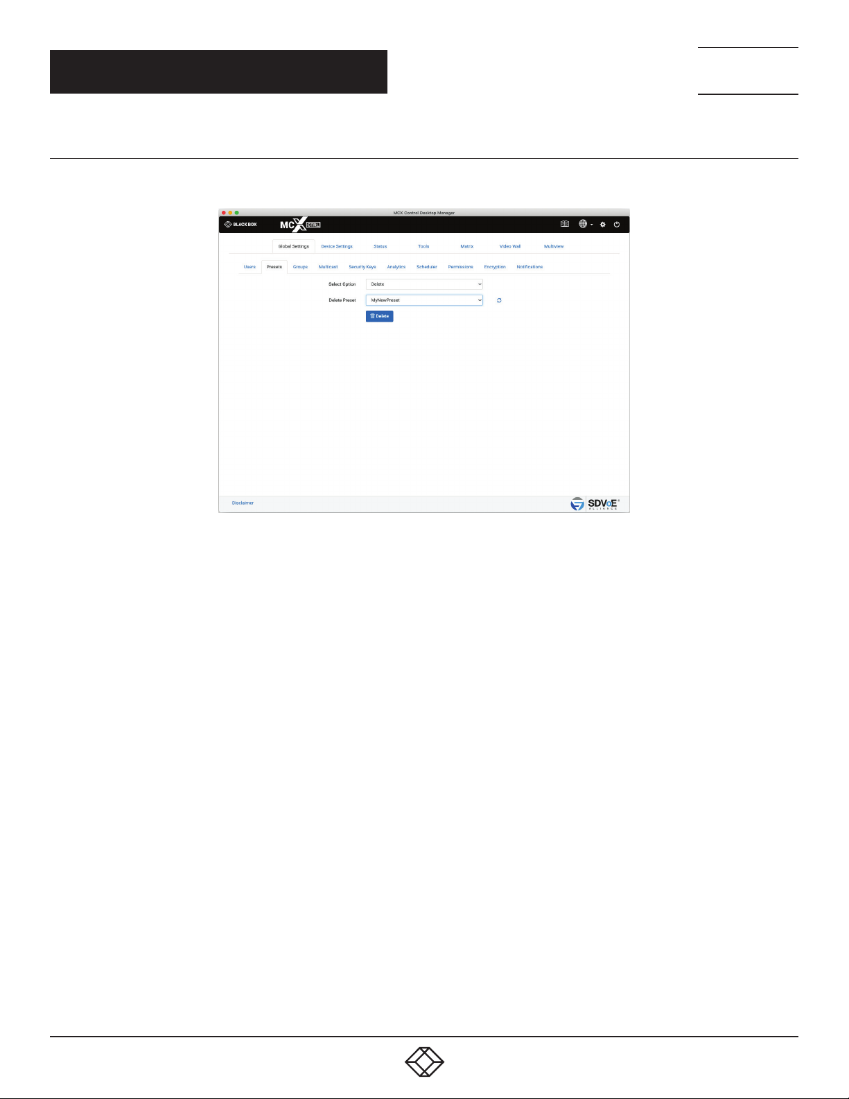
1.2.3 DELETE PRESET
Here you can delete any existing preset from the system.
NEED HELP?
LEAV E TH E TEC H TO US
LIVE 24/7
TECHNICAL
SUPPORT
1. 8 7 7. 8 7 7. 2 2 69
1. Select Delete
2. Select Preset
3. Click Delete button
FIGURE 1-8.
1. 8 77. 8 7 7. 2 2 69 BLACKBOX.COM
13
Page 14
CHAPTER 1: GLOBAL SETTINGS
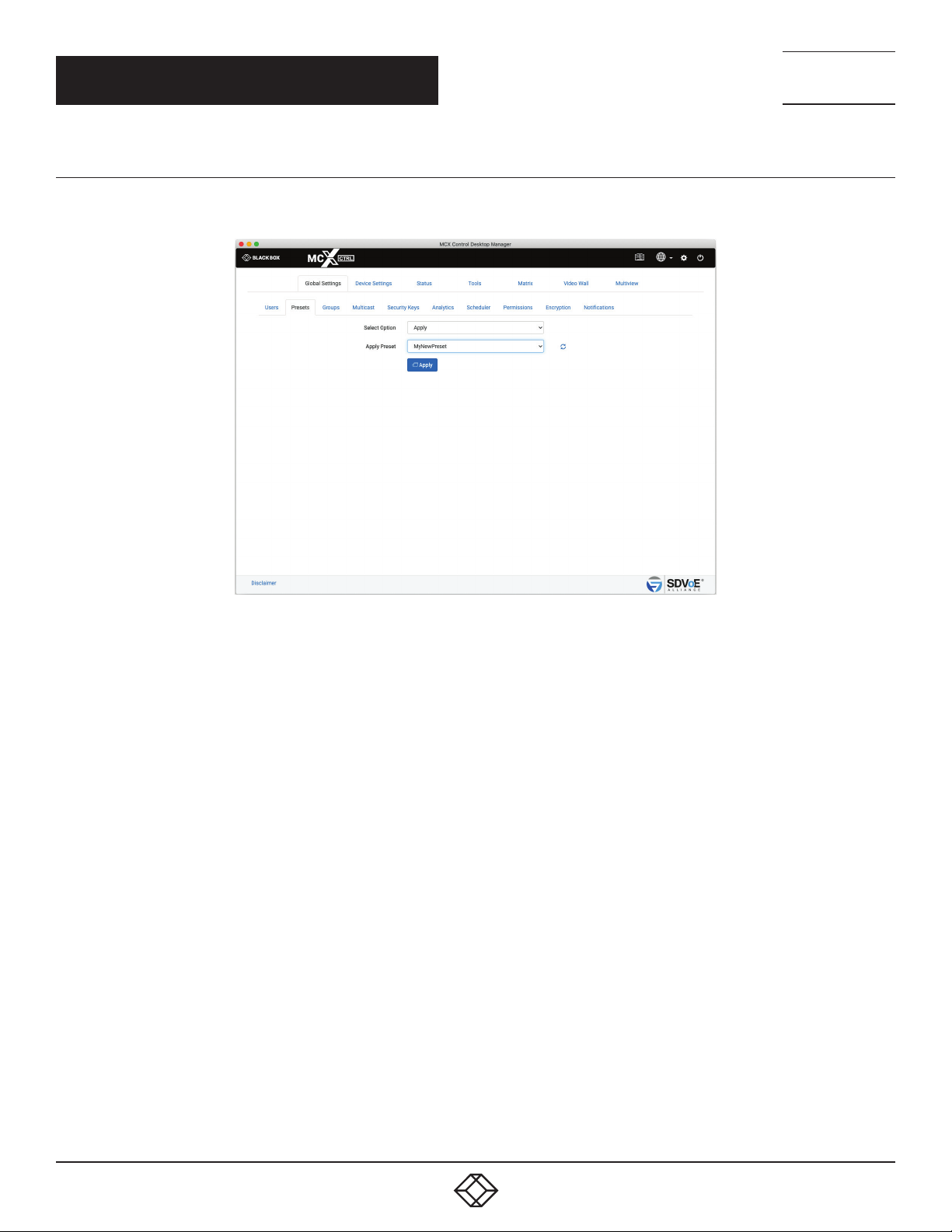
1.2.4 APPLY PRESET
Here you can apply any existing preset on the system.
NEED HELP?
LEAV E TH E TEC H TO US
LIVE 24/7
TECHNICAL
SUPPORT
1. 8 7 7. 8 7 7. 2 2 69
1. Select Apply
2. Select Preset
3. Click Apply button
FIGURE 1-9.
14
1. 8 77. 8 7 7. 2 2 69 BLACKBOX.COM
Page 15
NEED HELP?
LEAV E TH E TEC H TO US
LIVE 24/7
CHAPTER 1: GLOBAL SETTINGS
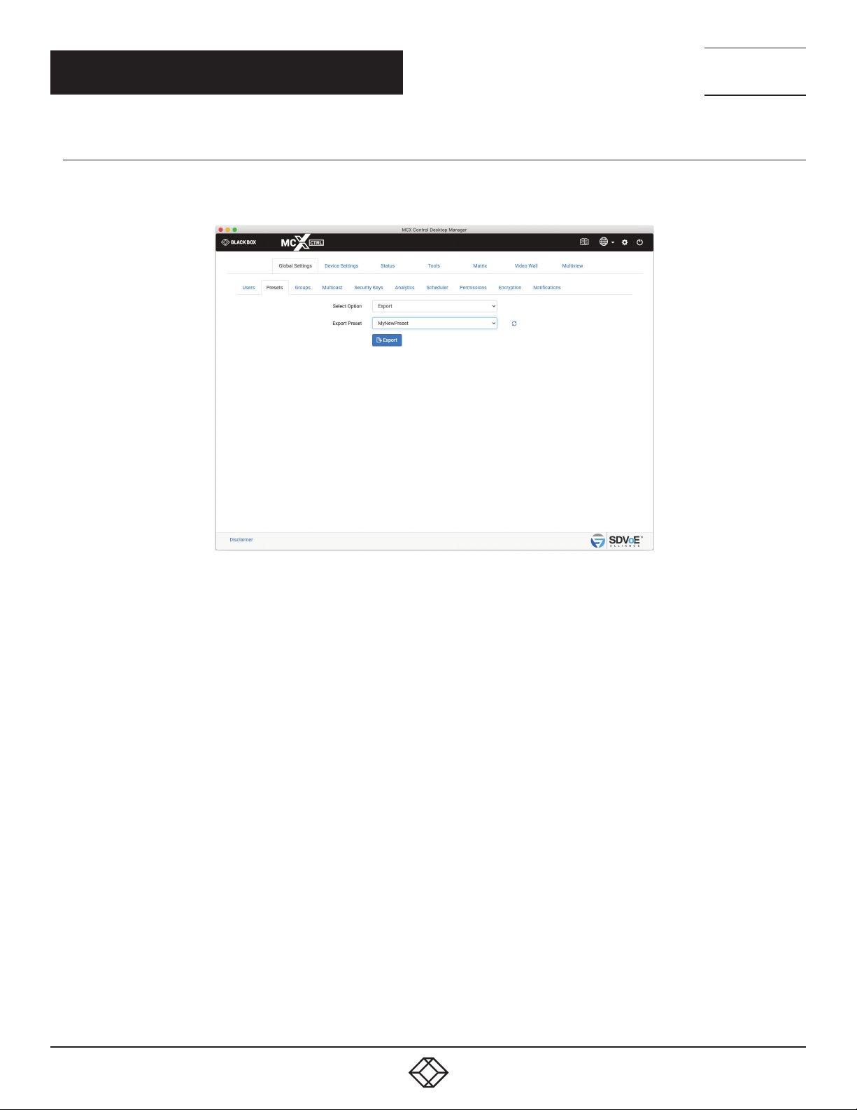
1.2.5 EXPORT PRESET
Here you can export an existing preset on the system which can then be used as a backup or edited. The preset will be saved to your
Downloads folder as an ini file like MyNewPreset.ini.
TECHNICAL
SUPPORT
1. 8 7 7. 8 7 7. 2 2 69
FIGURE 1-10.
1. Select Export
2. Select Preset
3. Click Export button
The export preset can be edited with an application like Notepad++, right click the file and select “Open with…”
1. 8 77. 8 7 7. 2 2 69 BLACKBOX.COM
15
Page 16
NEED HELP?
LEAV E TH E TEC H TO US
LIVE 24/7
CHAPTER 1: GLOBAL SETTINGS
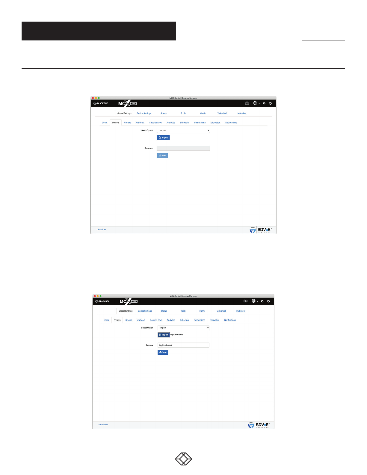
1.2.6 IMPORT PRESET
Here you can import a new preset into the system. (If updating an existing preset, the existing preset on the system will need to be deleted
prior to importing.)
TECHNICAL
SUPPORT
1. 8 7 7. 8 7 7. 2 2 69
1. Select Import
2. Click Import button
3. Select preset file
4. Click Open
FIGURE 1-11.
16
FIGURE 1-12.
1. 8 77. 8 7 7. 2 2 69 BLACKBOX.COM
Page 17
CHAPTER 1: GLOBAL SETTINGS
5*. Rename preset
6. Click Save button
1.2.7 PRESET RECORD
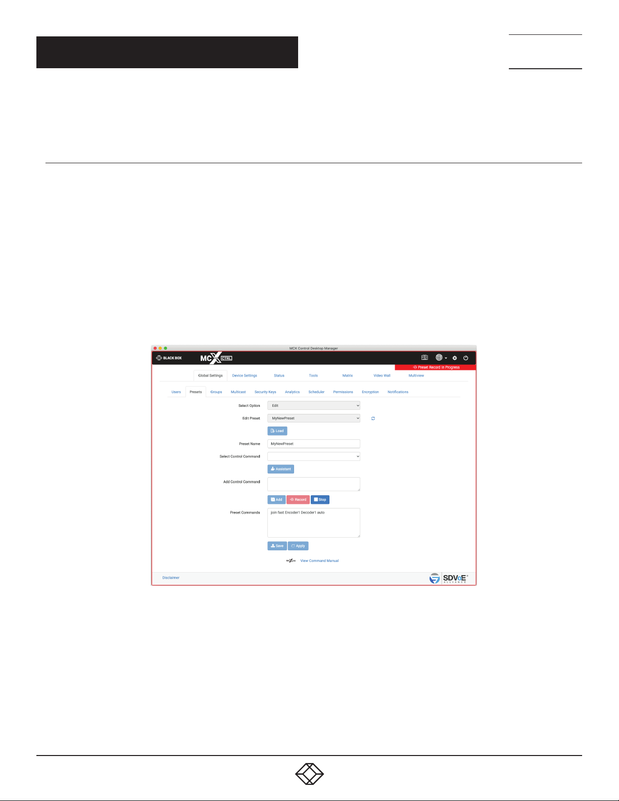
Selecting Record within Presets New or Presets Edit will record interactions from the UI directly into the selected preset.
The following UI tabs will record interactions:
Device Settings/Edit
Status/Details
Tools/Send Serial
Tools/Send Infrared
Tools/Send Control Command
Matrix
Video Wall
Multiview
NEED HELP?
LEAV E TH E TEC H TO US
LIVE 24/7
TECHNICAL
SUPPORT
1. 8 7 7. 8 7 7. 2 2 69
FIGURE 1-13.
1. Click Record to start recording
2. Click Stop to stop recording
3. Click “Preset Record In Progress” from any tab to return to the recording preset tab.
1. 8 77. 8 7 7. 2 2 69 BLACKBOX.COM
17
Page 18
NEED HELP?
LEAV E TH E TEC H TO US
LIVE 24/7
CHAPTER 1: GLOBAL SETTINGS
1.3 GROUPS
System Encoders and Decoders can be arranged into various groups. These groups can then be individually controlled via the API or
displayed in the UI. Here we manage the groups by adding, editing or deleting them. Once a group has been added to the system, the
group can then be assigned to any or all Encoders and Decoders from the Device Settings tab.
1.3.1 A DD G RO U P
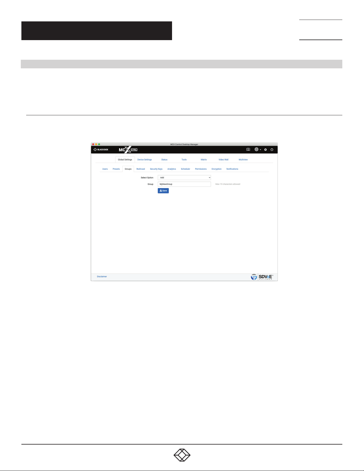
Here you can add a new group to the system to easily manage Encoders and Decoders. A group must be created before any Encoders or
Decoders can be assigned to it from Device Settings/Group.
TECHNICAL
SUPPORT
1. 8 7 7. 8 7 7. 2 2 69
1. Select Add
2. Enter a Group name
3. Click Save
18
FIGURE 1-14.
1. 8 77. 8 7 7. 2 2 69 BLACKBOX.COM
Page 19
CHAPTER 1: GLOBAL SETTINGS
1.3.2 EDIT GROUP
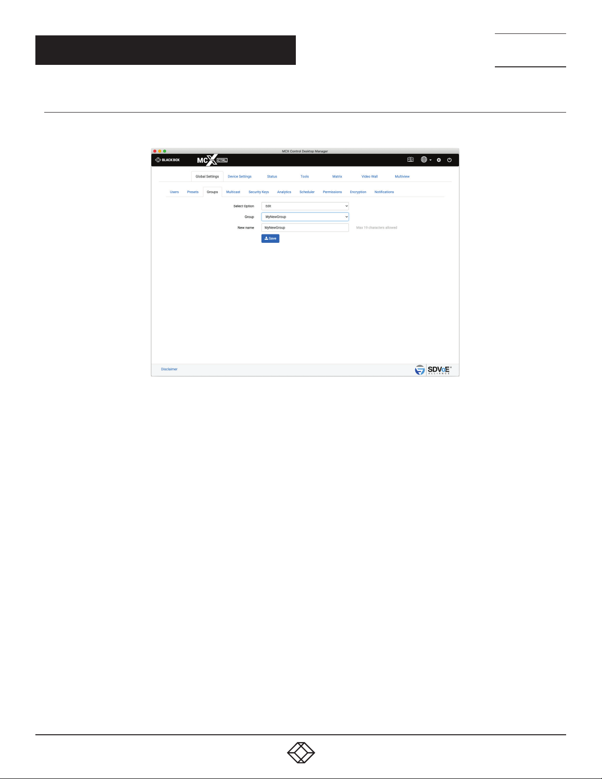
Here you can change the name of an existing group.
NEED HELP?
LEAV E TH E TEC H TO US
LIVE 24/7
TECHNICAL
SUPPORT
1. 8 7 7. 8 7 7. 2 2 69
1. Select Edit
2. Select Group
3. Enter a new name
4. Click Save button
FIGURE 1-15.
1. 8 77. 8 7 7. 2 2 69 BLACKBOX.COM
19
Page 20
CHAPTER 1: GLOBAL SETTINGS
1.3.3 DELETE GROUP
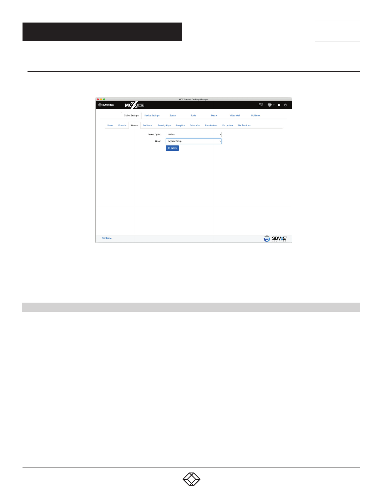
Here you can delete an existing group from the system.
NEED HELP?
LEAV E TH E TEC H TO US
LIVE 24/7
TECHNICAL
SUPPORT
1. 8 7 7. 8 7 7. 2 2 69
FIGURE 1-16.
1. Select Delete
2. Select Group
3. Click Delete
1.4 MULTICAST
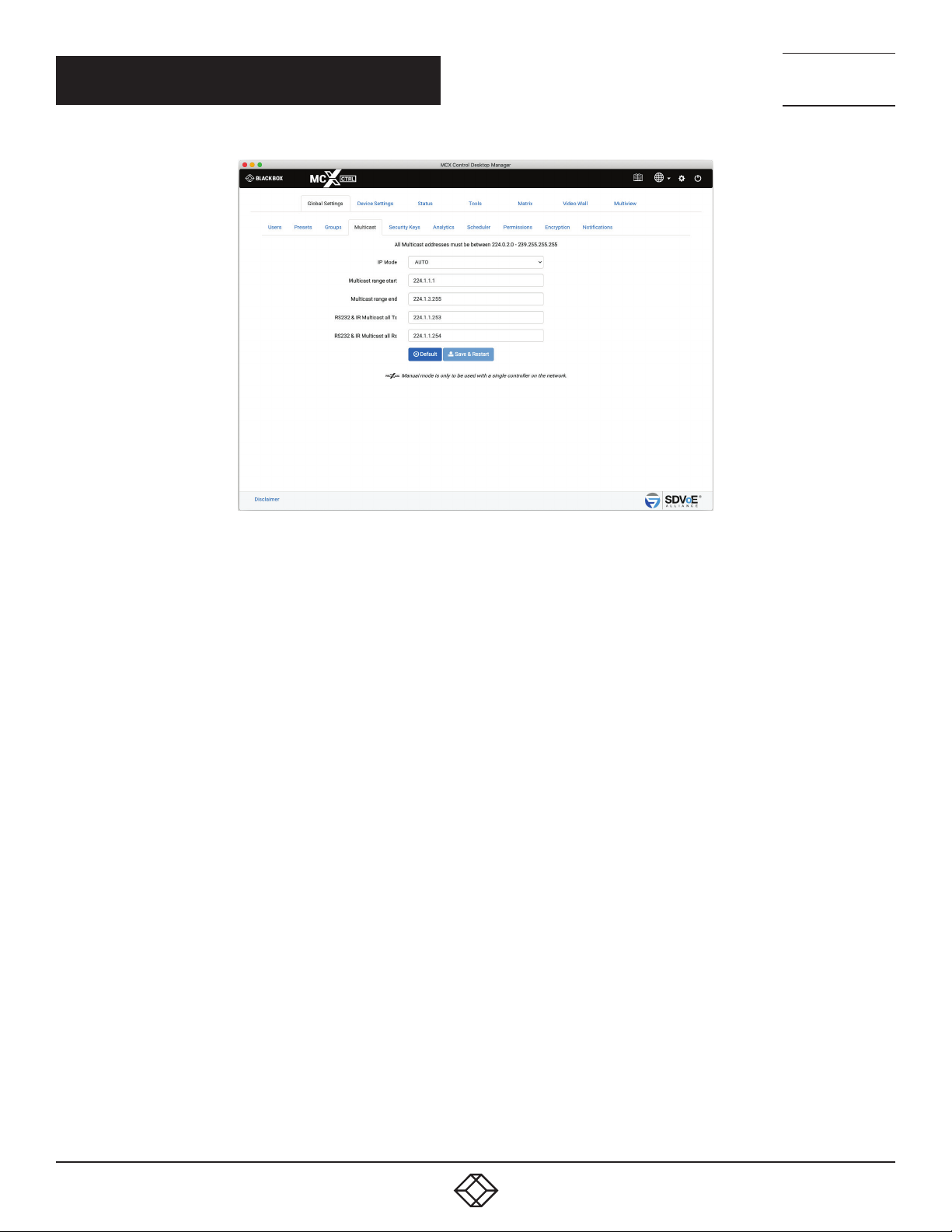
The Multicast section is used to initially set the system to use automatically assigned Multicast addresses within a specified range, or
manually assign a range of Multicast addresses per stream type.
When in AUTO mode, all stream types will be assigned the next available Multicast address when the stream is started.
When in MANUAL mode, all streams will have their own statically assigned Multicast addresses to use.
1.4.1 MULTICAST AUTO
Multicast Auto will automatically assign Multicast addresses to streams and is used by default. Device settings will not include a
Multicast tab to assign individual Multicast addresses to streams.
20
1. 8 77. 8 7 7. 2 2 69 BLACKBOX.COM
Page 21
CHAPTER 1: GLOBAL SETTINGS
NEED HELP?
LEAV E TH E TEC H TO US
LIVE 24/7
TECHNICAL
SUPPORT
1. 8 7 7. 8 7 7. 2 2 69
1. Select AUTO
2. Enter desired addresses or select Default values
3. Click Save & Restart to apply the changes
FIGURE 1-17.
1. 8 77. 8 7 7. 2 2 69 BLACKBOX.COM
21
Page 22
NEED HELP?
LEAV E TH E TEC H TO US
LIVE 24/7
CHAPTER 1: GLOBAL SETTINGS
1.4.2 MULTICAST MANUAL
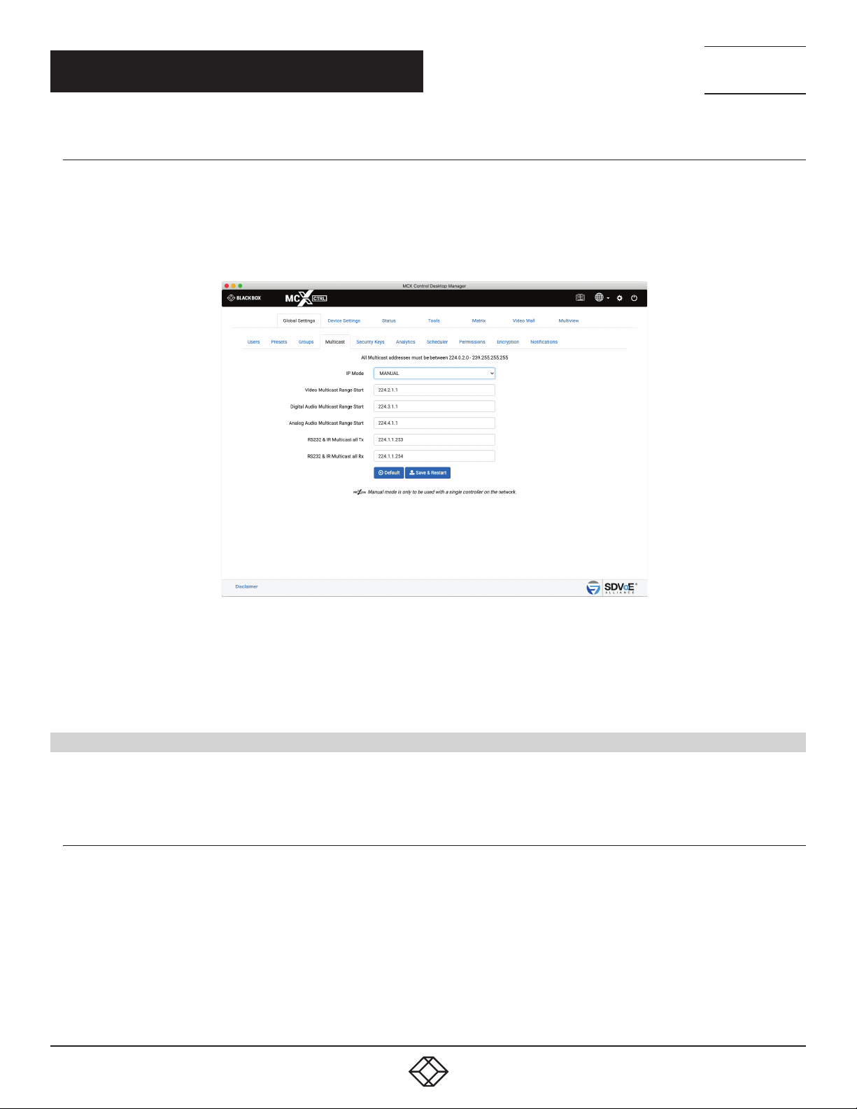
Multicast Manual will initially assign static Multicast addresses to all Encoder stream types. Manual mode by default allocates a starting
range address for the separate stream types in different subnets to ensure there is no possibility of mixed subscriptions whereby a
Decoder might receive a video stream on an audio subscription. So by default all video streams will use the 224.2.x.x range, all digital
audio streams will use the 224.3.x.x range and analog audio will use the 224.4.x.x range.
Device settings will now include a Multicast tab to assign individual Multicast addresses to streams.
TECHNICAL
SUPPORT
1. 8 7 7. 8 7 7. 2 2 69
FIGURE 1-18.
1. Select MANUAL
2. Enter IP addresses or select Default values
3. Click Save & Restart to apply the changes
1.5 SECURITY KEYS
Security keys are required with all HTTP level requests and optional for TCP commands on port 6980. Only keys generated from the
software can be used.
1.5.1 HTTP API SECURIT Y KEY
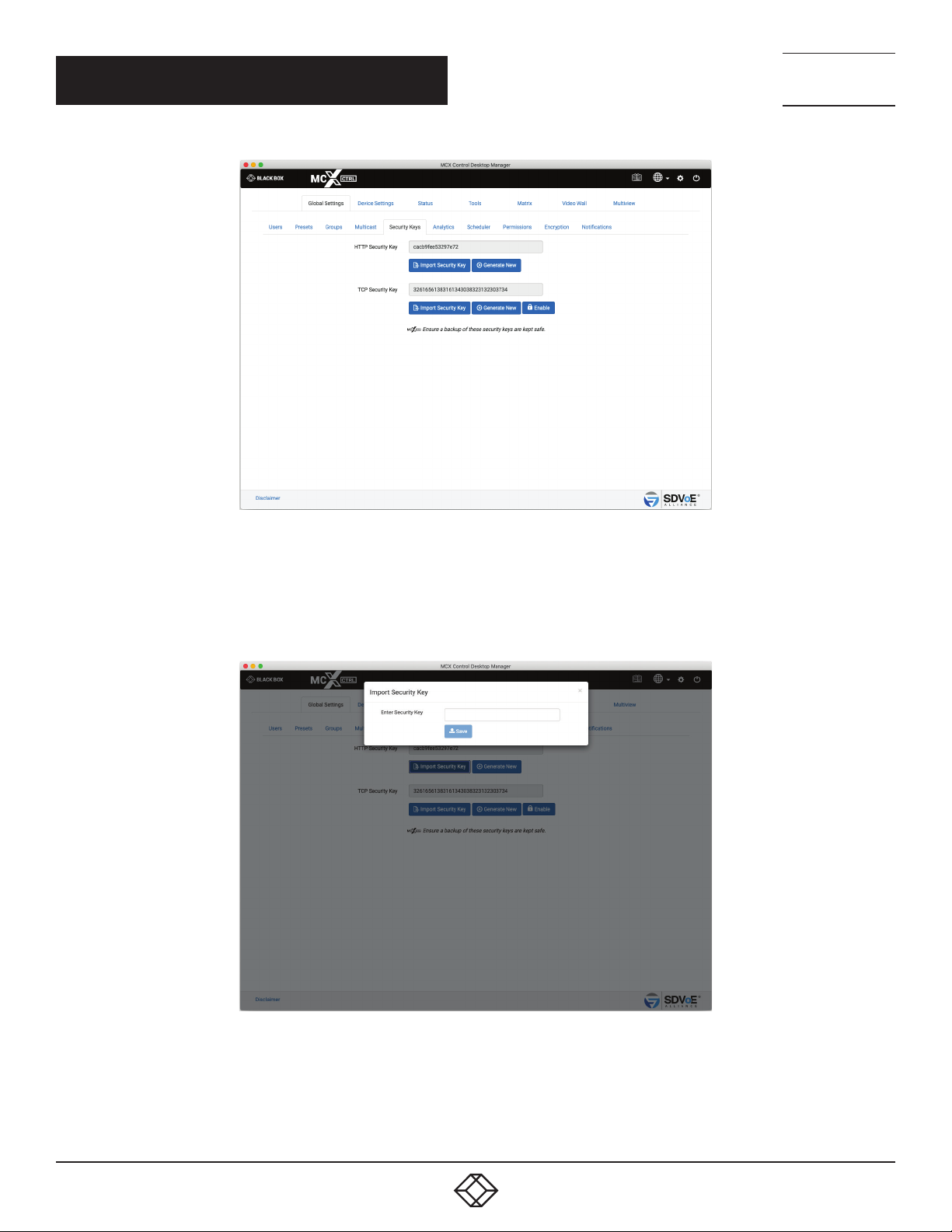
The MCX Network Management Controller can be accessed via HTTP GET and POST requests. To ensure security over the internet, a
HTTP security key is required to be passed with all such requests. Here you can generate a new key or import a saved key that had been
previously generated.
22
1. 8 77. 8 7 7. 2 2 69 BLACKBOX.COM
Page 23
CHAPTER 1: GLOBAL SETTINGS
NEED HELP?
LEAV E TH E TEC H TO US
LIVE 24/7
TECHNICAL
SUPPORT
1. 8 7 7. 8 7 7. 2 2 69
Importing an HTTP API Security Key
1. Enter the Security Key.
2. Click Save button.
FIGURE 1-19.
FIGURE 1-20.
1. 8 77. 8 7 7. 2 2 69 BLACKBOX.COM
23
Page 24
NEED HELP?
LEAV E TH E TEC H TO US
LIVE 24/7
CHAPTER 1: GLOBAL SETTINGS
1.5.2 TCP SECURIT Y KEY
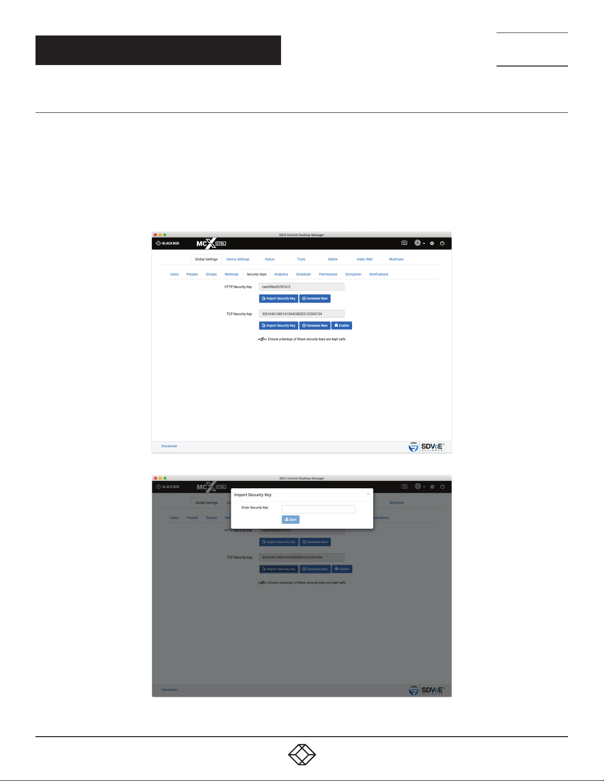
The MCX Network Management Controller can be accessed via Telnet requests on TCP port 6980. To ensure security over the network a
TCP security key can be passed with all such commands. Here you can generate a new key or import a saved key that had been previously
generated. As the TCP security key is optional, its use can be Enabled or Disabled from here.
Importing a TCP API Security Key
1. Enter the Security Key.
2. Click the Save button.
3. Click the Enable button.
TECHNICAL
SUPPORT
1. 8 7 7. 8 7 7. 2 2 69
FIGURE 1-21.
FIGURE 1-22.
24
1. 8 77. 8 7 7. 2 2 69 BLACKBOX.COM
Page 25
NEED HELP?
LEAV E TH E TEC H TO US
LIVE 24/7
CHAPTER 1: GLOBAL SETTINGS
TECHNICAL
SUPPORT
1. 8 7 7. 8 7 7. 2 2 69
1.6 ANALYTICS
Analytical data is constantly being stored on the system. By default data will be maintained for 1 month, but this can be changed up to 12
months.
Various types of information is stored and can be exported for use in a 3rd party analytical application such as Microsoft’s Power Bi.
Internal results for the following can be generated from the UI:
Source Availability: The Source Availability represents the time in hours an Encoder has video signal.
Display Availability: The Display Availability represents the time in hours a Decoder has a monitor connected.
Source Resolution: The Source Resolution represents the combination of different resolutions used as a source.
Source Count: The Source Count represents the number of times an Encoder detects a source available.
Display Count: The Display Count represents the number of times a Decoder detects a display available.
Display Source Change: The Display Source Change represents the number of times a Decoder has been switched to an Encoder.
Network Downtime: The Network Downtime represents the time in hours a device is missing from the network.
Temperature: The Temperature represents the operating temperature in either °C or °F of a device.
Bandwidth: The Bandwidth represents the total bandwidth of an Encoder in Gbps.
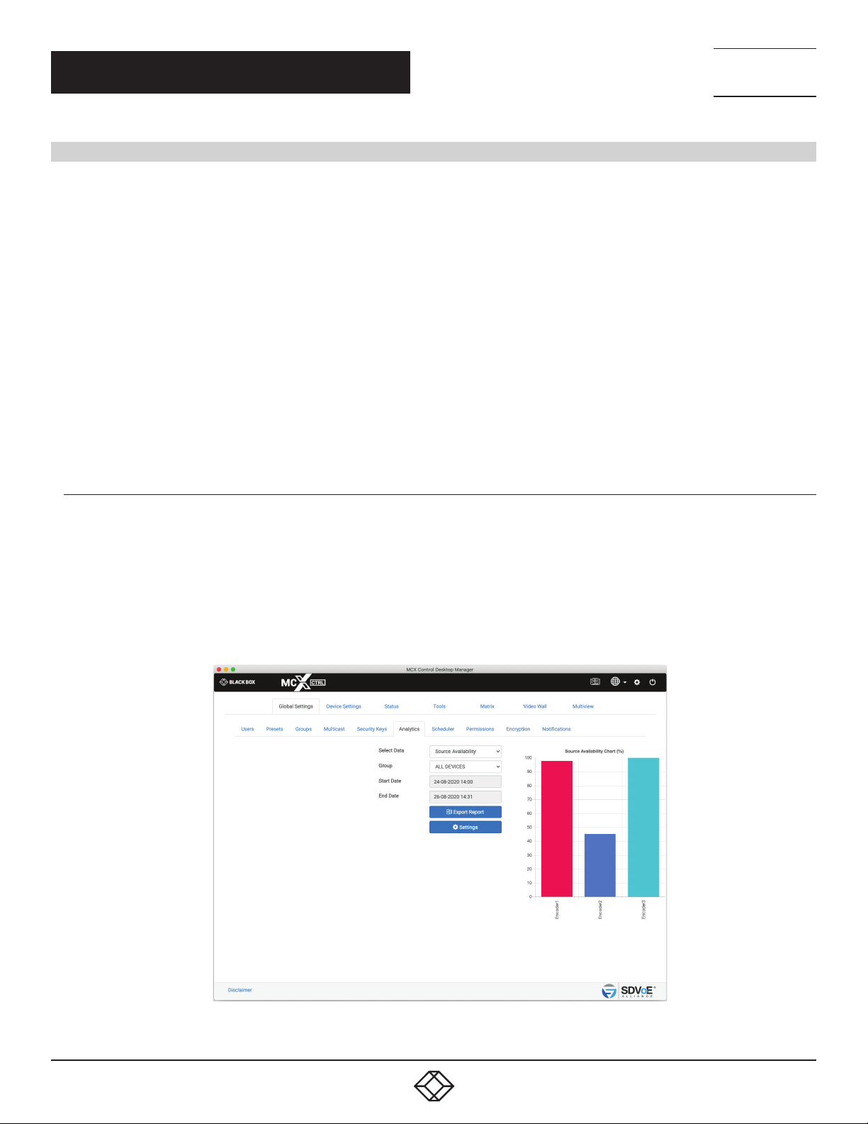
1.6.1 SOURCE AVAILABILIT Y
The Source Availability represents the time in hours an Encoder has video signal.
1. Select Source Availability
2. Select Group
3. Select Start Date
4. Select End Date
5. Click Export Report
FIGURE 1-23.
1. 8 77. 8 7 7. 2 2 69 BLACKBOX.COM
25
Page 26
CHAPTER 1: GLOBAL SETTINGS
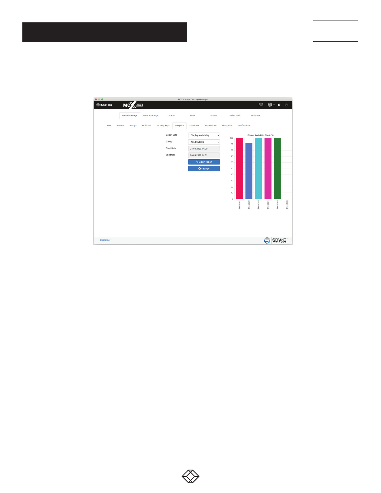
1.6.2 DISPLAY AVAILABILITY
The Display Availability represents the time in hours a Decoder has a monitor connected.
NEED HELP?
LEAV E TH E TEC H TO US
LIVE 24/7
TECHNICAL
SUPPORT
1. 8 7 7. 8 7 7. 2 2 69
1. Select Display Availability
2. Select Group
3. Select Start Date
4. Select End Date
5. Click Export Report
FIGURE 1-24.
26
1. 8 77. 8 7 7. 2 2 69 BLACKBOX.COM
Page 27
CHAPTER 1: GLOBAL SETTINGS
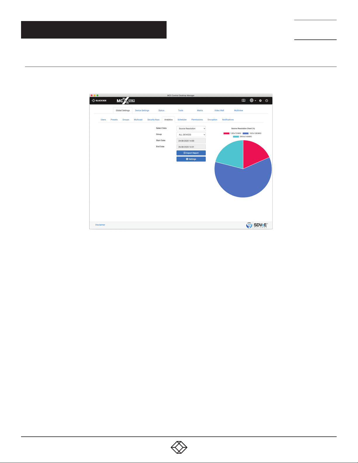
1.6.3 SOURCE RESOLUTION
The Source Resolution represents the combination of different resolutions used as a source.
NEED HELP?
LEAV E TH E TEC H TO US
LIVE 24/7
TECHNICAL
SUPPORT
1. 8 7 7. 8 7 7. 2 2 69
1. Select Source Resolution
2. Select Group
3. Select Start Date
4. Select End Date
5*. Click Export Report
FIGURE 1-25.
1. 8 77. 8 7 7. 2 2 69 BLACKBOX.COM
27
Page 28
CHAPTER 1: GLOBAL SETTINGS
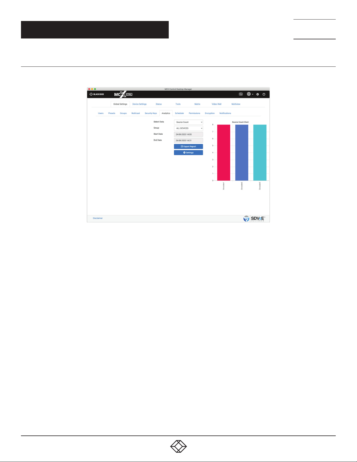
1.6.4 SOURCE COUNT
The Source Count represents the number of times an Encoder detects a source available.
NEED HELP?
LEAV E TH E TEC H TO US
LIVE 24/7
TECHNICAL
SUPPORT
1. 8 7 7. 8 7 7. 2 2 69
1. Select Source Count
2. Select Group
3. Select Start Date
4. Select End Date
5*. Click Export Report
FIGURE 1-26.
28
1. 8 77. 8 7 7. 2 2 69 BLACKBOX.COM
Page 29
CHAPTER 1: GLOBAL SETTINGS
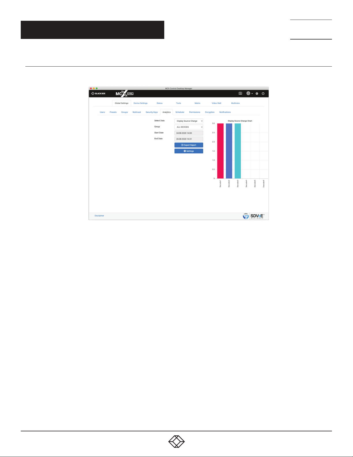
1.6.5 DISPL AY C O U NT
The Display Count represents the number of times a Decoder detects a display available.
NEED HELP?
LEAV E TH E TEC H TO US
LIVE 24/7
TECHNICAL
SUPPORT
1. 8 7 7. 8 7 7. 2 2 69
1. Select Display Count
2. Select Group
3. Select Start Date
4. Select End Date
5*. Click Export Report
FIGURE 1-27.
1. 8 77. 8 7 7. 2 2 69 BLACKBOX.COM
29
Page 30
CHAPTER 1: GLOBAL SETTINGS
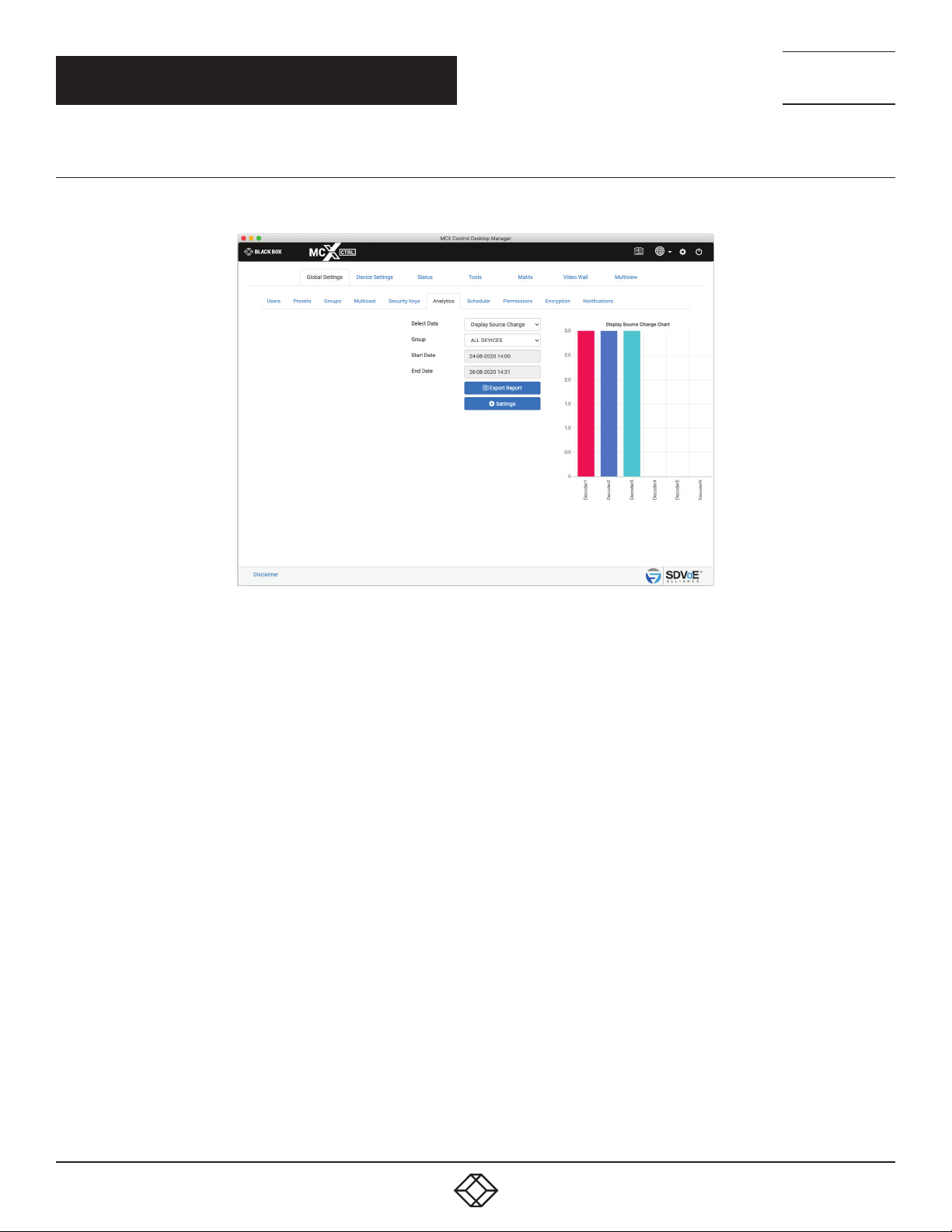
1.6.6 DISPLAY SOURCE CHANGE
The Display Source Change represents the number of times a Decoder has been switched to an Encoder.
NEED HELP?
LEAV E TH E TEC H TO US
LIVE 24/7
TECHNICAL
SUPPORT
1. 8 7 7. 8 7 7. 2 2 69
1. Select Source Change
2. Select Group
3. Select Start Date
4. Select End Date
5*. Click Export Report
FIGURE 1-28.
30
1. 8 77. 8 7 7. 2 2 69 BLACKBOX.COM
Page 31
CHAPTER 1: GLOBAL SETTINGS
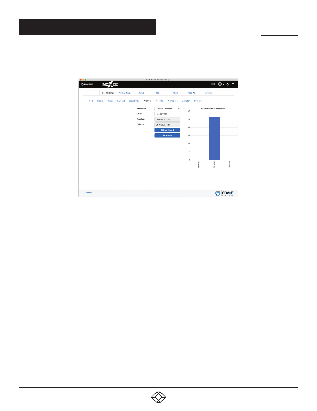
1.6.7 NETWORK DOWNTIME
The Network Downtime represents the time in hours a device is disconnected from the network.
NEED HELP?
LEAV E TH E TEC H TO US
LIVE 24/7
TECHNICAL
SUPPORT
1. 8 7 7. 8 7 7. 2 2 69
1. Select Network Downtime
2. Select Group
3. Select Start Date
4. Select End Date
5*. Click Export Report
FIGURE 1-29.
1. 8 77. 8 7 7. 2 2 69 BLACKBOX.COM
31
Page 32
CHAPTER 1: GLOBAL SETTINGS
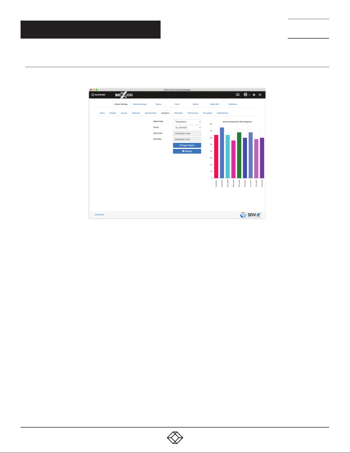
1.6.8 TEMPERATURE
The Temperature represents the operating temperature in either °C or °F of a device.
NEED HELP?
LEAV E TH E TEC H TO US
LIVE 24/7
TECHNICAL
SUPPORT
1. 8 7 7. 8 7 7. 2 2 69
1. Select Temperature
2. Select Group
3. Select Start Date
4. Select End Date
5*. Click Export Report
FIGURE 1-30.
32
1. 8 77. 8 7 7. 2 2 69 BLACKBOX.COM
Page 33
CHAPTER 1: GLOBAL SETTINGS
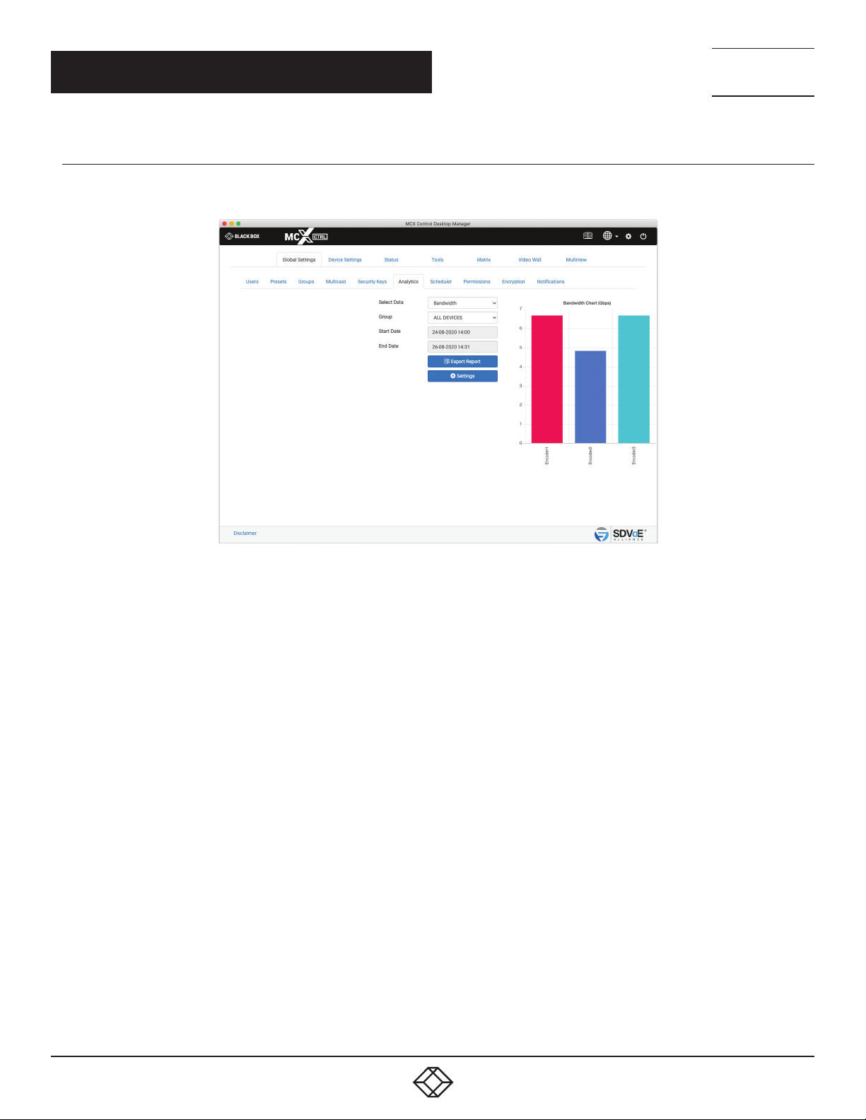
1.6.9 B A NDWIDTH
The Bandwidth represents the total Encoder bandwidth in Gbps.
NEED HELP?
LEAV E TH E TEC H TO US
LIVE 24/7
TECHNICAL
SUPPORT
1. 8 7 7. 8 7 7. 2 2 69
1. Select Bandwidth
2. Select Group
3. Select Start Date
4. Select End Date
5. Click Export Report
FIGURE 1-31.
1. 8 77. 8 7 7. 2 2 69 BLACKBOX.COM
33
Page 34
CHAPTER 1: GLOBAL SETTINGS
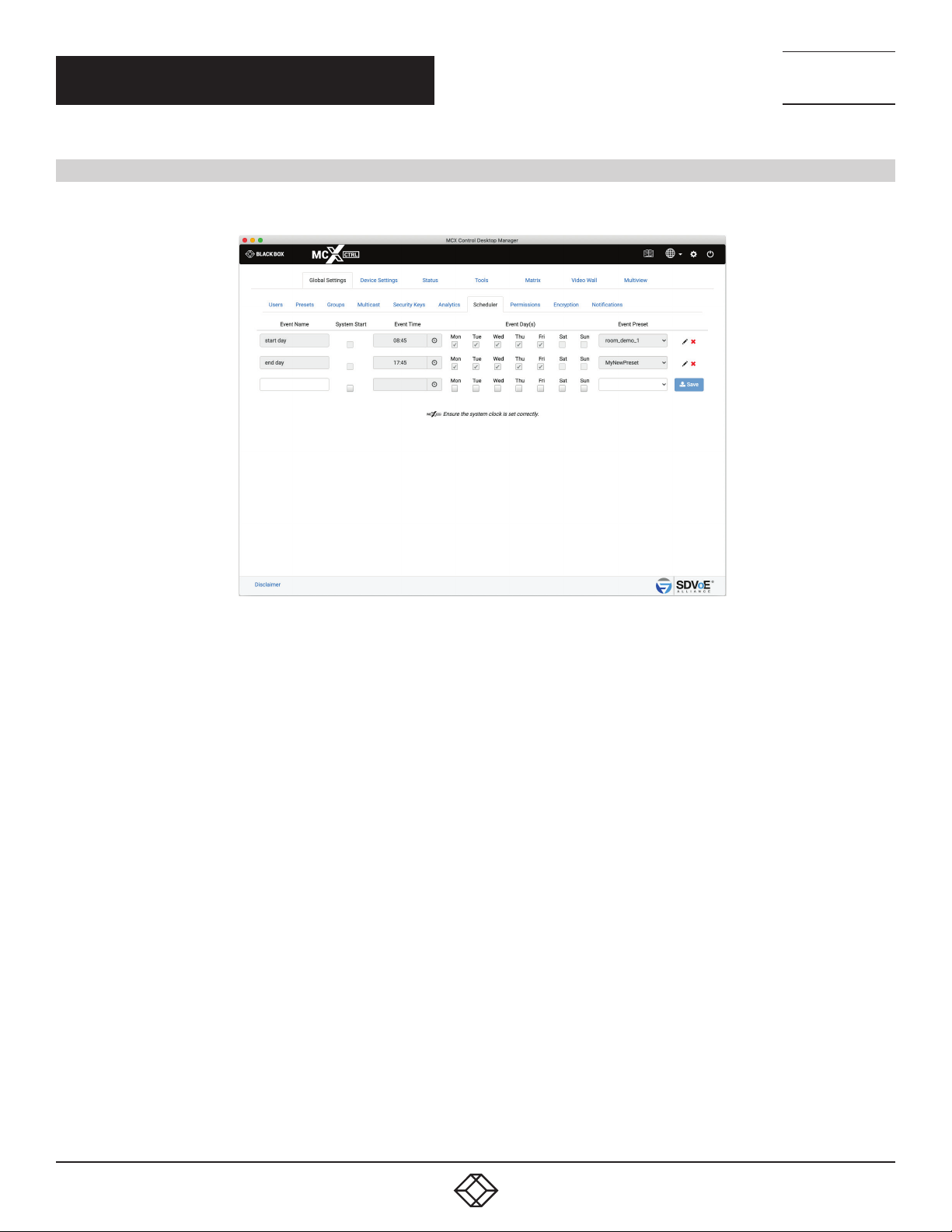
1.7 SCHEDULER
The Scheduler is used to apply presets at a particular time of a given day or system start.
NEED HELP?
LEAV E TH E TEC H TO US
LIVE 24/7
TECHNICAL
SUPPORT
1. 8 7 7. 8 7 7. 2 2 69
1. Enter a name
2. Select a time
3. Select day(s)
4. Select preset
5. Click Save button
6*. Once saved, the pen icon is used to edit the event
7*. Click the cross icon to delete the event
FIGURE 1-32.
34
1. 8 77. 8 7 7. 2 2 69 BLACKBOX.COM
Page 35
NEED HELP?
LEAV E TH E TEC H TO US
LIVE 24/7
CHAPTER 1: GLOBAL SETTINGS
1.8 PERMISSIONS
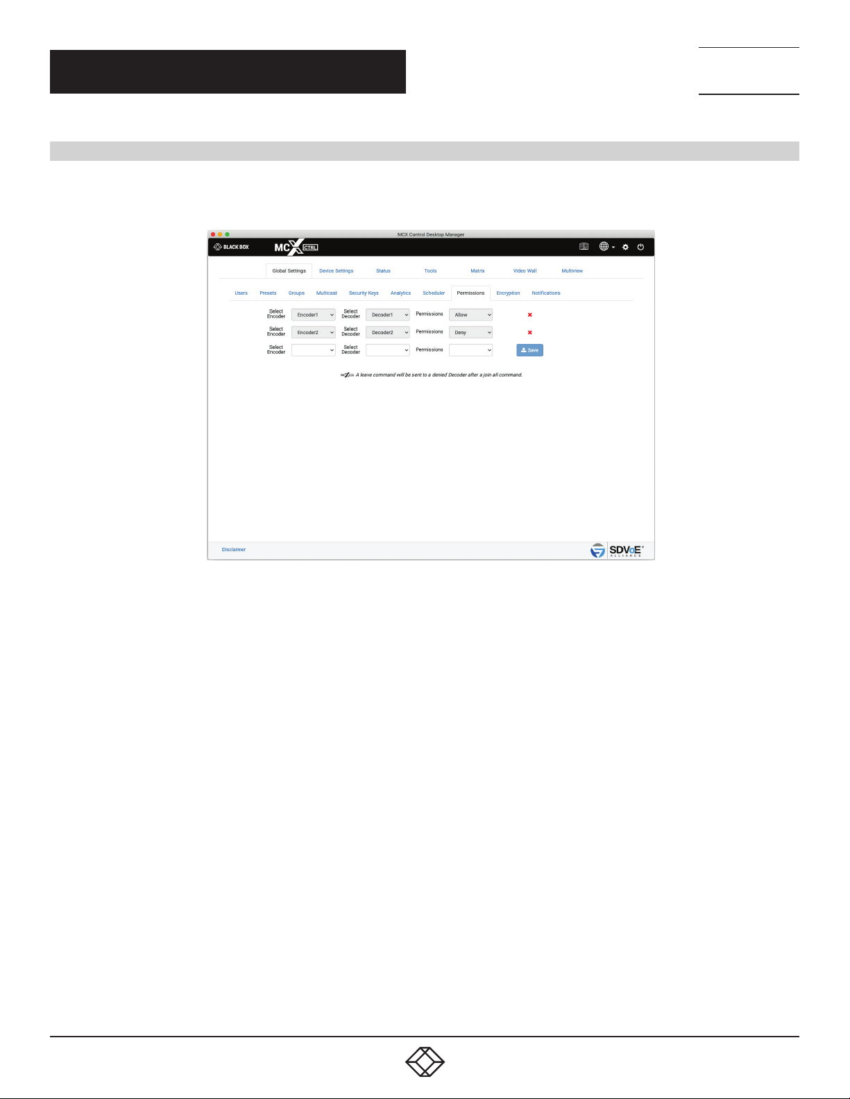
Permissions adds the ability to only allow certain Encoders to be joined with certain Decoders. Here Encoder1 is only allowed to be joined
with Decoder1, and Encoder2 can be joined with any Decoder except for Decoder2. Multiple conditions can be applied. Joining point-topoint the following rules will be considered before applying the join. Joining point-to-all the following rules will be applied after the join.
TECHNICAL
SUPPORT
1. 8 7 7. 8 7 7. 2 2 69
1. Select Encoder
2. Select Decoder
3. Select either Allow or Deny
4. Click Save button
5*. Select the cross icon to delete
FIGURE 1-33.
1. 8 77. 8 7 7. 2 2 69 BLACKBOX.COM
35
Page 36
NEED HELP?
LEAV E TH E TEC H TO US
LIVE 24/7
CHAPTER 1: GLOBAL SETTINGS
1.9 ENCRYPTION
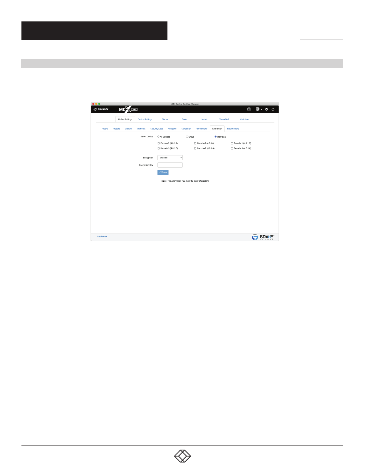
Encryption can be applied to an Encoder’s HDMI AV network data. A user defined key is set and only Decoders with the same key will be
able to decrypt the HDMI AV network data.
(Device firmware > 3.5.2.0 and MCX firmware > 2.14.0 required)
TECHNICAL
SUPPORT
1. 8 7 7. 8 7 7. 2 2 69
1. Select device(s)
2. Enable / Disable encryption
3. Enter Encryption Key (when Enabled)
4. Click Save button
FIGURE 1-34.
36
1. 8 77. 8 7 7. 2 2 69 BLACKBOX.COM
Page 37
CHAPTER 1: GLOBAL SETTINGS
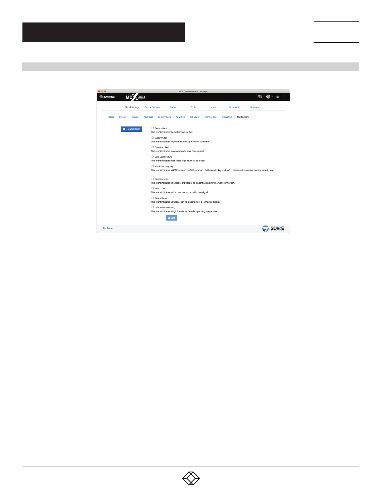
1.10 NOTIFICATIONS
Notifications will send E-Mail alerts whenever a selected event occurs on the system.
NEED HELP?
LEAV E TH E TEC H TO US
LIVE 24/7
TECHNICAL
SUPPORT
1. 8 7 7. 8 7 7. 2 2 69
1. Select events
2. Click Save button
FIGURE 1-35.
1. 8 77. 8 7 7. 2 2 69 BLACKBOX.COM
37
Page 38
NEED HELP?
LEAV E TH E TEC H TO US
LIVE 24/7
CHAPTER 1: GLOBAL SETTINGS
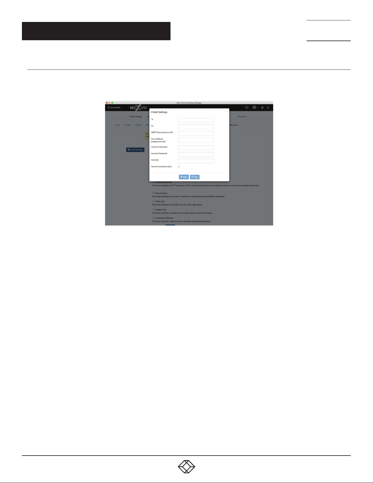
1.10.1 EMAIL SETTINGS
Here you configure the Email client to allow notification alerts to be sent from a specified Email account. The Test button sends a
confirmation Email to confirm the settings are correct.
TECHNICAL
SUPPORT
1. 8 7 7. 8 7 7. 2 2 69
FIGURE 1-35.
38
1. 8 77. 8 7 7. 2 2 69 BLACKBOX.COM
Page 39
NEED HELP?
LEAV E TH E TEC H TO US
LIVE 24/7
CHAPTER 2: DEVICE SETTINGS
TECHNICAL
SUPPORT
1. 8 7 7. 8 7 7. 2 2 69
2. DEVICE SETTINGS
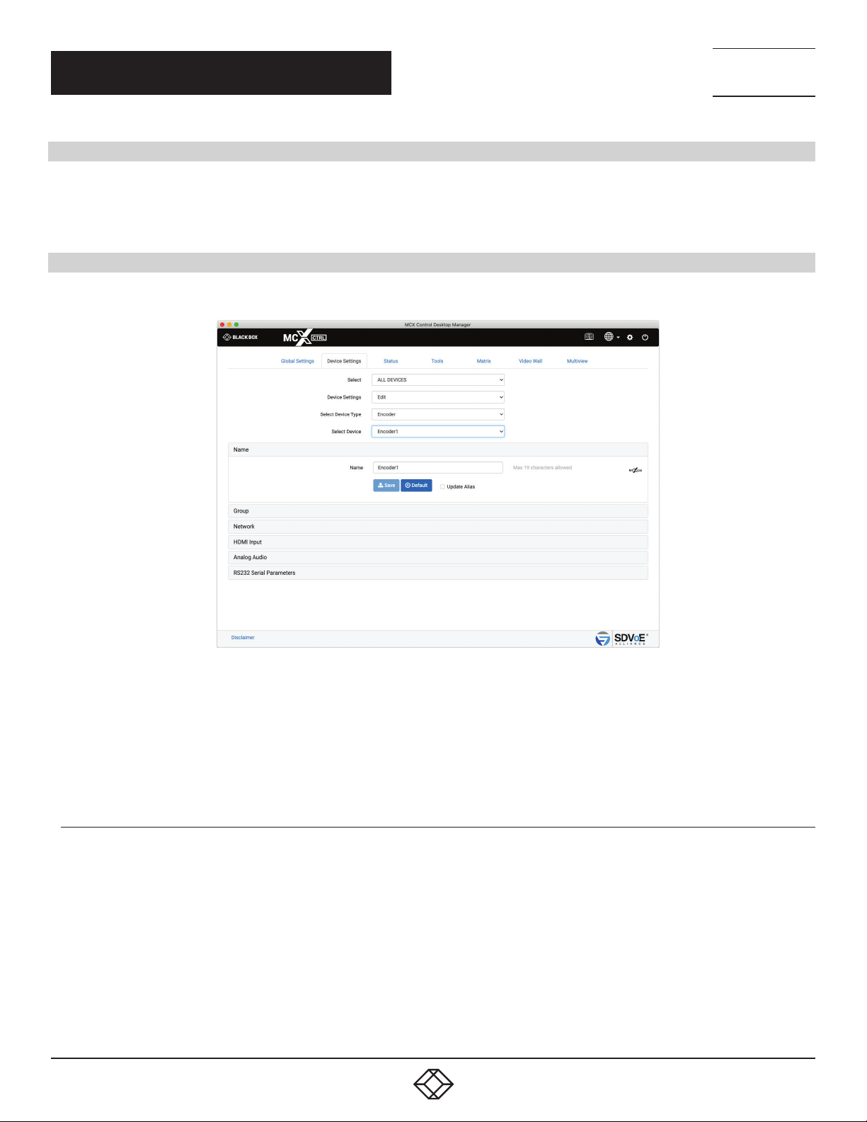
This is where all the Encoders and Decoders are configured. Encoders and Decoders can be individually configured or all together taking
advantage of exporting the csv formatted data and manipulating it as required before importing it back into the system. All changes made
in the DeviceExport.csv configuration file will be applied to the Encoders and Decoders.
2.1 E D IT SE TT I NGS
Here you can change the device settings for all Encoders and Decoders on the system.
FIGURE 2-1.
* Here you can change the device name
1. Select Edit
2. Select Encoder or Decoder
3. Select Device
2.1.1 N AME
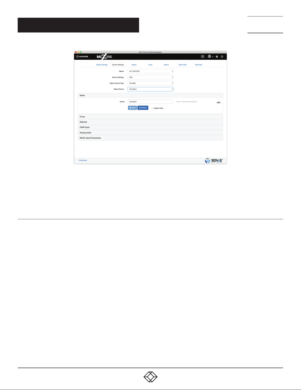
The name of the device is used for control. This is the device name used in API commands. Device names have a maximum of 19
characters and no spaces are allowed.
1. 8 77. 8 7 7. 2 2 69 BLACKBOX.COM
39
Page 40
CHAPTER 2: DEVICE SETTINGS
NEED HELP?
LEAV E TH E TEC H TO US
LIVE 24/7
TECHNICAL
SUPPORT
1. 8 7 7. 8 7 7. 2 2 69
FIGURE 2-2.
1. Enter Name or click Default button
2*. Select Update Alias
3. Click Save button
2.1.2 GROUPS
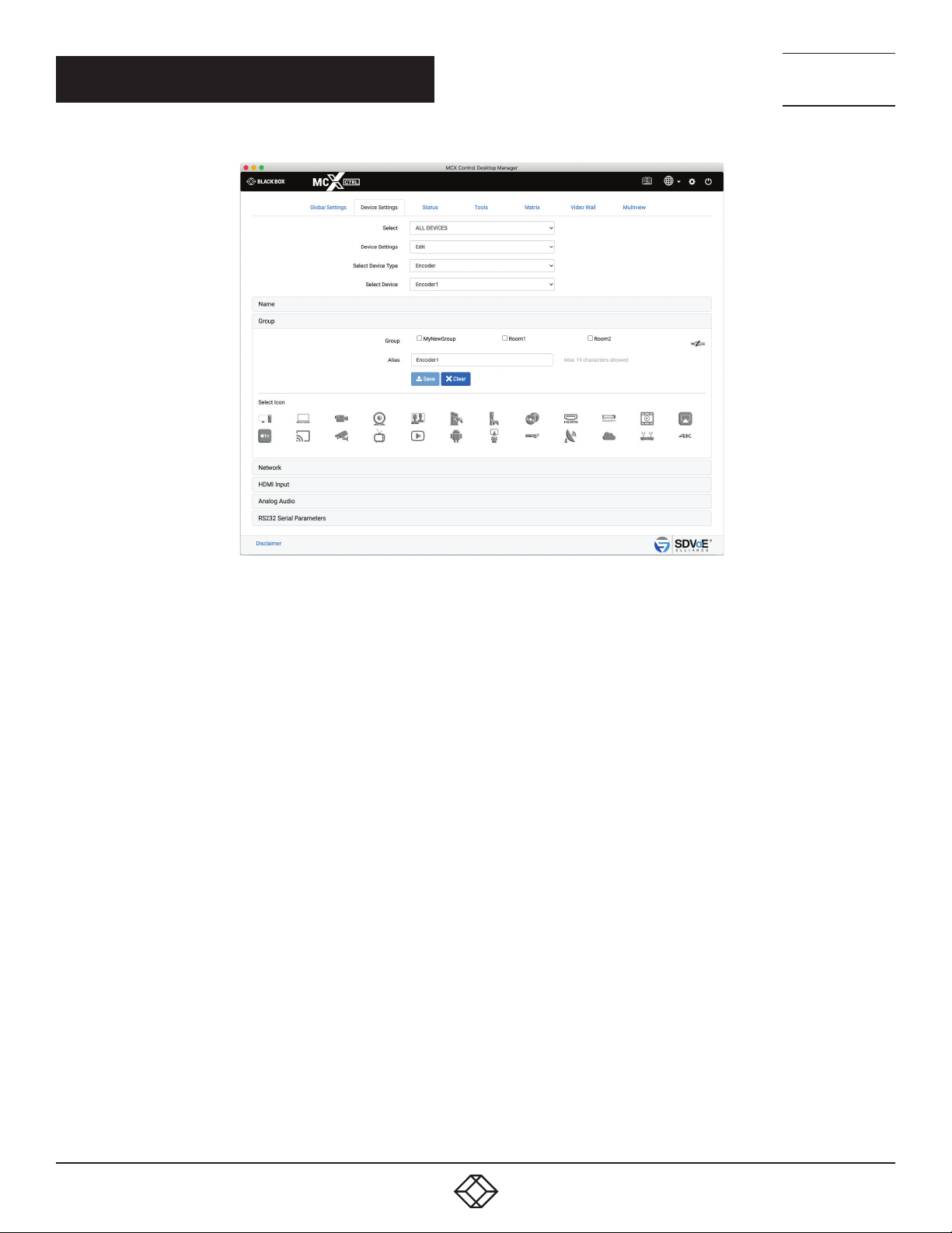
Encoders and Decoders can be assigned to groups. These groups are created from the Global Settings tab. Once an Encoder or Decoder
has been placed in a group, an alias name and an icon can be assigned to it. This alias name and icon will then be used on the matrix page
once a group is selected.
Group names have a maximum of 19 characters and no spaces are allowed.
40
1. 8 77. 8 7 7. 2 2 69 BLACKBOX.COM
Page 41
CHAPTER 2: DEVICE SETTINGS
NEED HELP?
LEAV E TH E TEC H TO US
LIVE 24/7
TECHNICAL
SUPPORT
1. 8 7 7. 8 7 7. 2 2 69
1. Select Group
2. Enter an Alias
3. Select an icon
4. Click Save button
FIGURE 2-3.
1. 8 77. 8 7 7. 2 2 69 BLACKBOX.COM
41
Page 42
CHAPTER 2: DEVICE SETTINGS
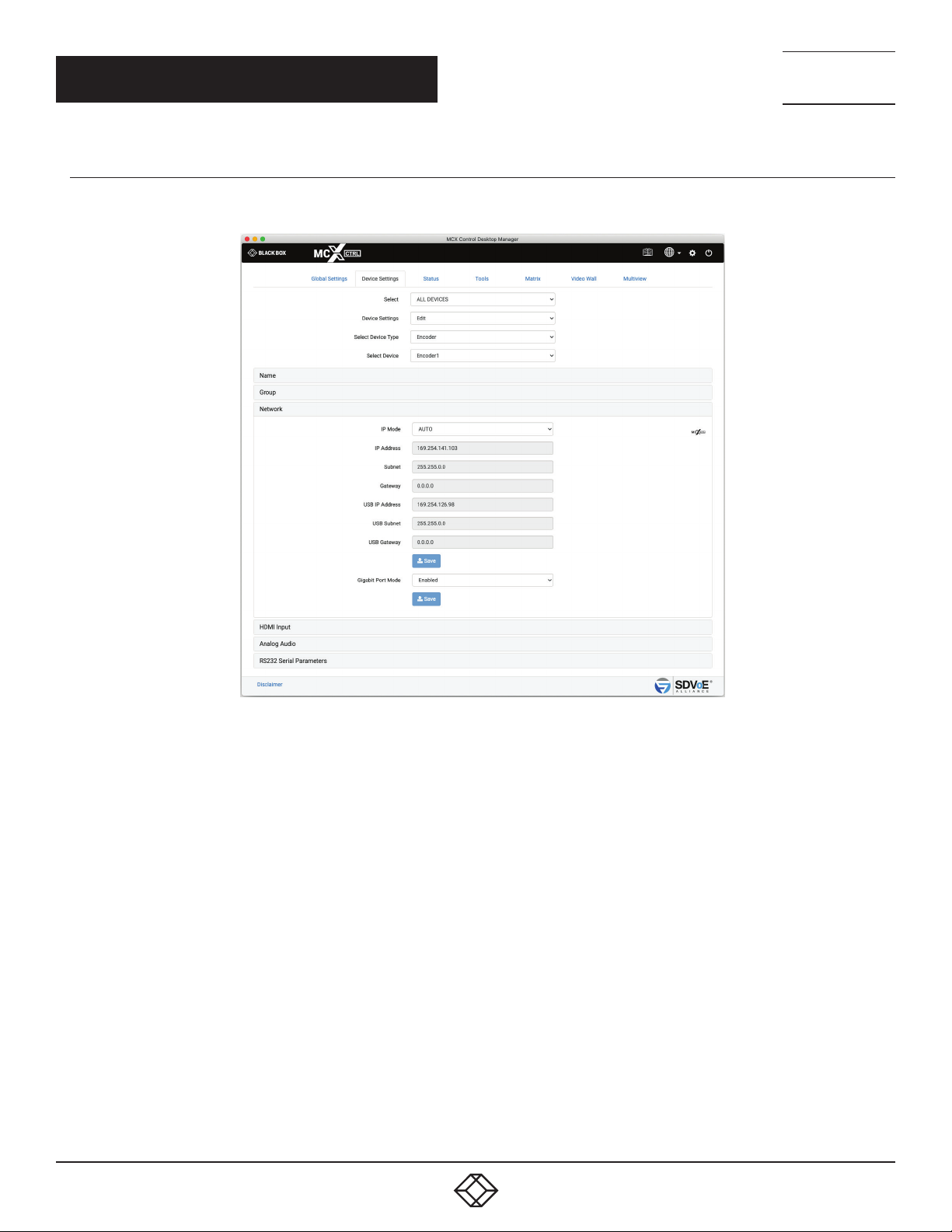
2.1.3 NETWORK INTERFACE
To assign DHCP so the device is automatically assigned an IP address, select AUTO.
NEED HELP?
LEAV E TH E TEC H TO US
LIVE 24/7
TECHNICAL
SUPPORT
1. 8 7 7. 8 7 7. 2 2 69
FIGURE 2-4.
1. Select IP Mode AUTO
2. Click Save button
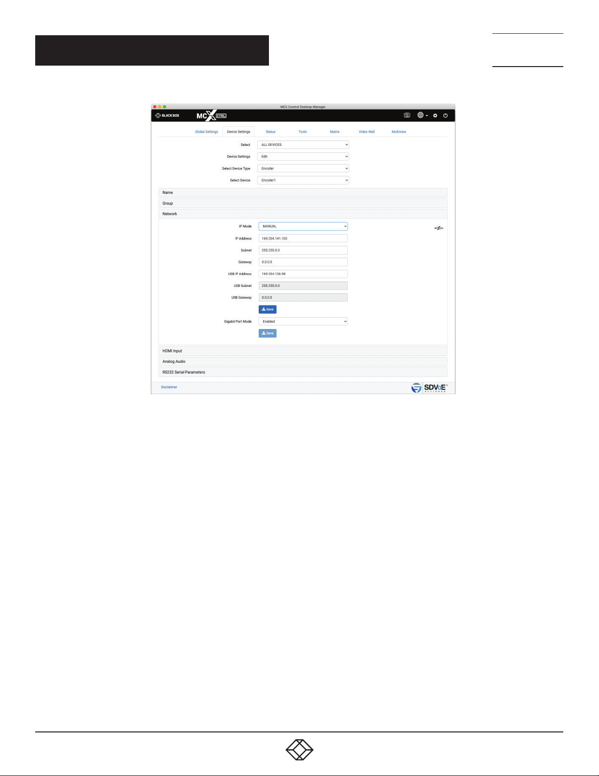
To assign a static IP address select MANUAL, then enter the details.
42
1. 8 77. 8 7 7. 2 2 69 BLACKBOX.COM
Page 43
CHAPTER 2: DEVICE SETTINGS
NEED HELP?
LEAV E TH E TEC H TO US
LIVE 24/7
TECHNICAL
SUPPORT
1. 8 7 7. 8 7 7. 2 2 69
1. Select IP Mode MANUAL
2. Enter an IP Address
3. Enter a Subnet
4. Enter a Gateway
5. Click Save button
FIGURE 2-5.
1. 8 77. 8 7 7. 2 2 69 BLACKBOX.COM
43
Page 44
CHAPTER 2: DEVICE SETTINGS
The function of the local 1 Gigabit network port can be enabled or disabled from here.
1. Select Enable or Disable
2. Click Save button
2.1.4 HDMI/DP INTERFACE
Here you assign settings to the video input of an Encoder.
NEED HELP?
LEAV E TH E TEC H TO US
LIVE 24/7
TECHNICAL
SUPPORT
1. 8 7 7. 8 7 7. 2 2 69
44
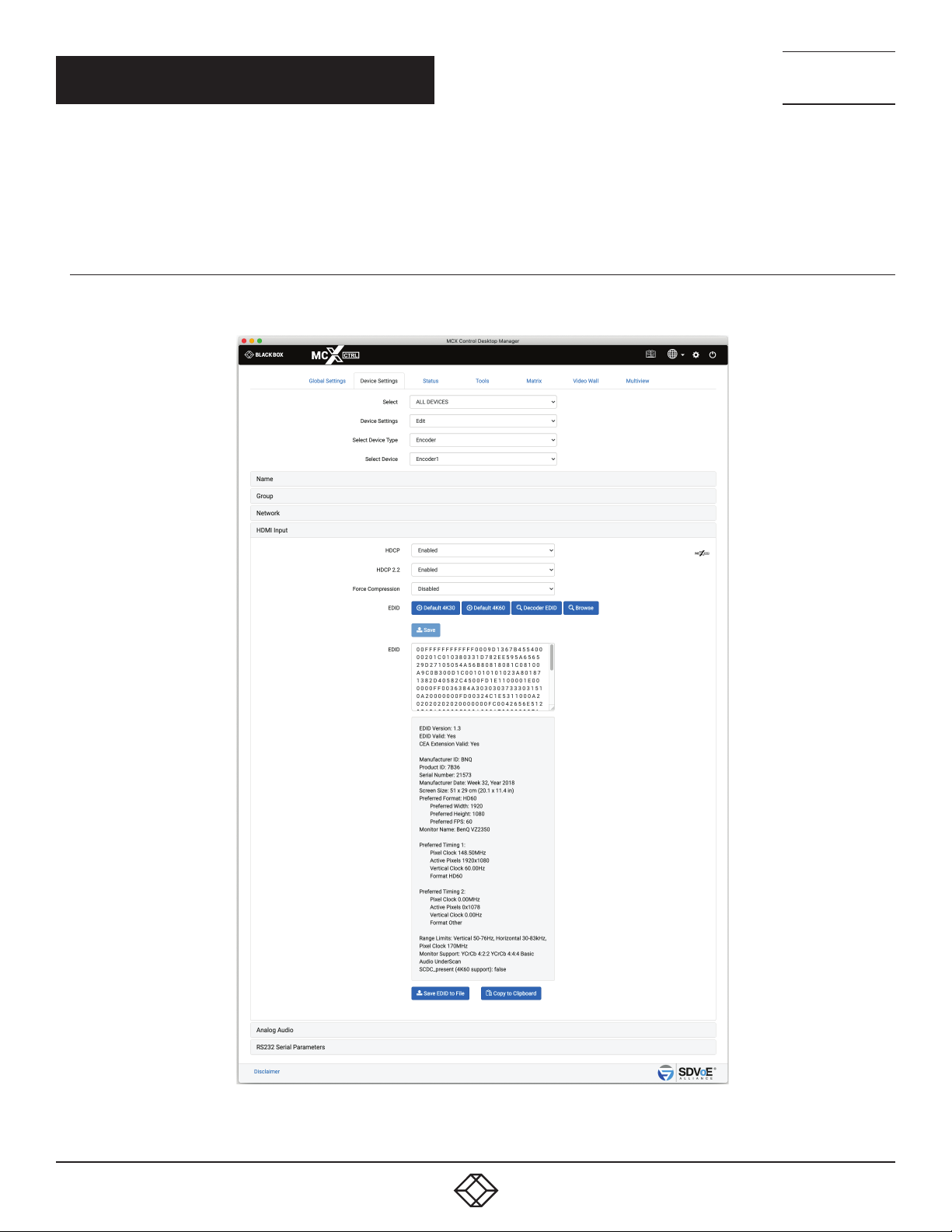
FIGURE 2-6.
1. 8 77. 8 7 7. 2 2 69 BLACKBOX.COM
Page 45
NEED HELP?
LEAV E TH E TEC H TO US
LIVE 24/7
CHAPTER 2: DEVICE SETTINGS
TECHNICAL
SUPPORT
1. 8 7 7. 8 7 7. 2 2 69
* Select Browse to copy the EDID directly from any Decoder. Only Decoders with a Display connected will be shown
1. Select Input HDMI/DisplayPort/AUTO
2. Enable/Disable HDCP
3. Enable/Disable HDCP2.2
4. Enable/Disable compression
5. Select EDID
6. Click Save button
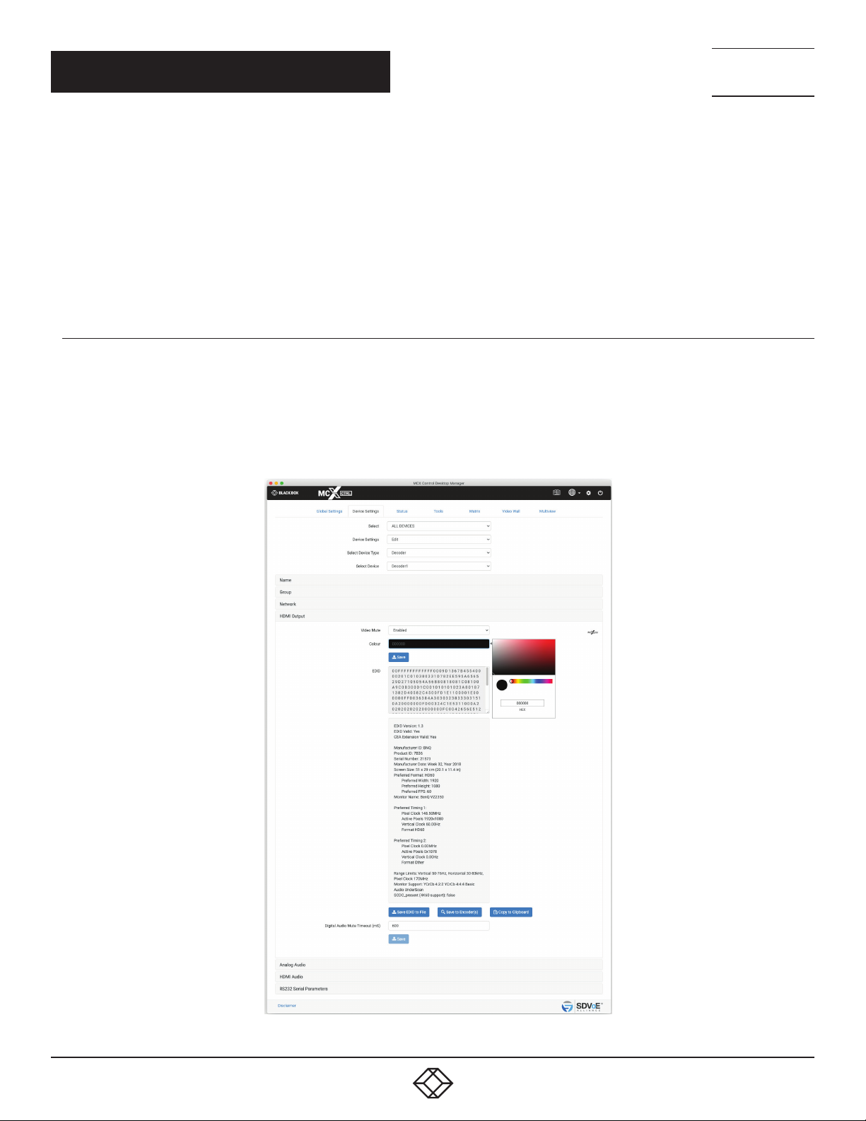
2.1.5 HDMI INTERFACE (DECODER)
Here you can view and save the EDID from the Decoder. The EDID can also be loaded to selected Encoders.
The Decoder’s video Mute status and color can also be set from here. This mute feature is only supported when the Decoder is in a
display mode other than sync_scale.
Digital audio mute timeout can also be adjusted if required. This is the amount of time in milliseconds the HDMI audio is muted after a
join to prevent audio popping. Some displays require longer than others to prevent audible noise during a join. The default is 600 with a
range from 0 to 5000. (Device firmware > 3.5.2.0 and MCX firmware > 2.14.0 required)
FIGURE 2-7.
1. 8 77. 8 7 7. 2 2 69 BLACKBOX.COM
45
Page 46
NEED HELP?
LEAV E TH E TEC H TO US
LIVE 24/7
CHAPTER 2: DEVICE SETTINGS
1. The EDID can be saved to a file, sent directly to Encoders or copied to the clipboard.
2. The Decoder’s displays video mute status can be Enabled or Disabled.
3. If the Decoder’s displays video is muted select a color.
4. Click the Save button
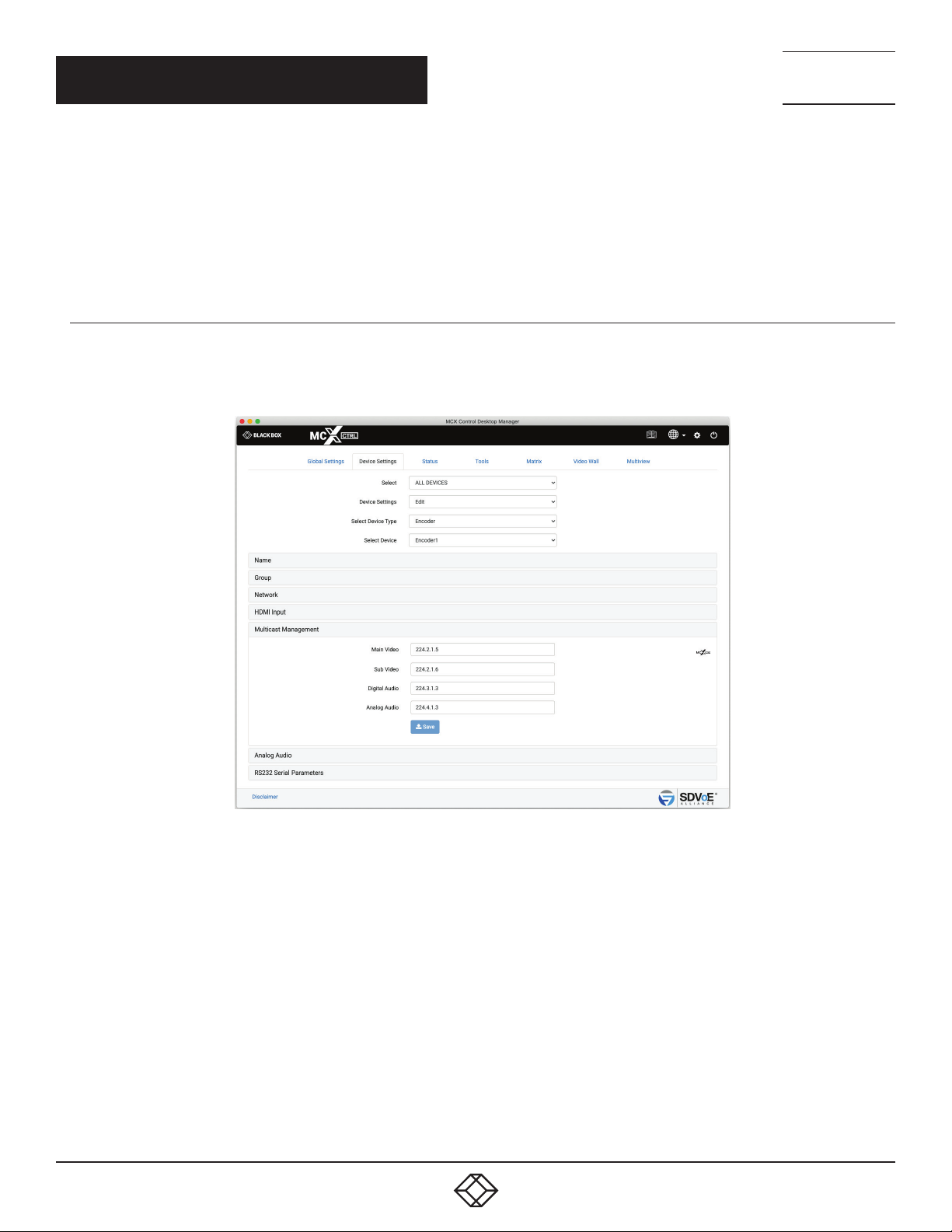
2.1.6 MULTICAST MANAGEMENT
When Multicast has been set to MANUAL from the Global Settings\Multicast tab, an Encoder will show the Multicast Management tab.
Multicast Addresses will be automatically assigned and these can be manually changed as required. Make sure Multicast addresses are
assigned in the same range as specified on the Global Settings\Multicast tab.
TECHNICAL
SUPPORT
1. 8 7 7. 8 7 7. 2 2 69
1. Enter Main Video address
2. Enter Sub Video address
3. Enter Digital Audio address
4. Enter Analog Audio address
5. Click Save button
46
FIGURE 2-8.
1. 8 77. 8 7 7. 2 2 69 BLACKBOX.COM
Page 47
CHAPTER 2: DEVICE SETTINGS
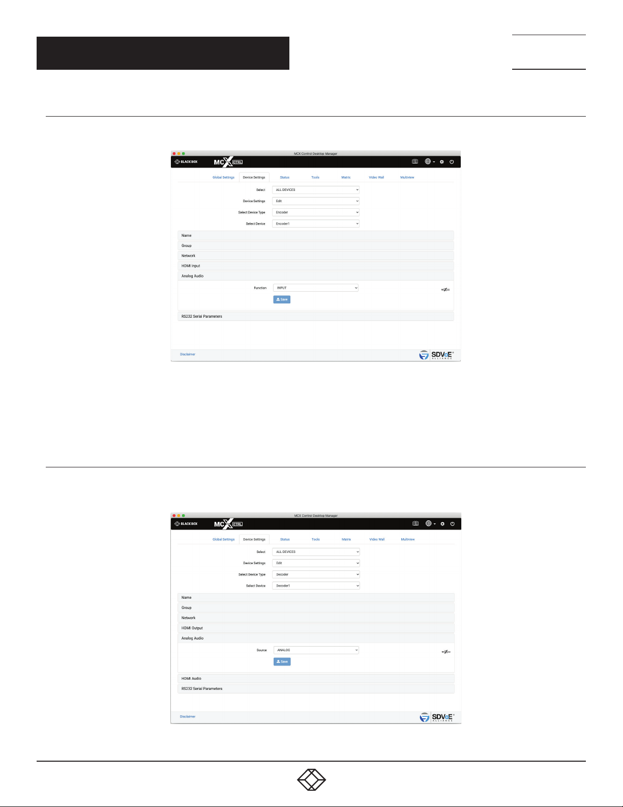
2.1.7 ANALOG AUDIO INTERFACE
The 3.5-mm analog audio jack of an Encoder can work as either an input or an output.
NEED HELP?
LEAV E TH E TEC H TO US
LIVE 24/7
TECHNICAL
SUPPORT
1. 8 7 7. 8 7 7. 2 2 69
FIGURE 2-9.
1. Select either INPUT or OUTPUT
2. Click Save button
2.1.8 ANALOG AUDIO JACK
The 3.5mm analog audio jack of a Decoder can output analog audio either from the HDMI or Analog sources. To de-embed the HDMI
audio select HDMI otherwise the analog audio source of an Encoder will be used.
FIGURE 2-10.
1. 8 77. 8 7 7. 2 2 69 BLACKBOX.COM
47
Page 48
CHAPTER 2: DEVICE SETTINGS
1. Select either ANALOG or HDMI
2. Click Save button
2.1.9 HDMI AUDIO SOURCE
The audio of the HDMI can be either the original HDMI audio or the analog audio from an Encoder.
NEED HELP?
LEAV E TH E TEC H TO US
LIVE 24/7
TECHNICAL
SUPPORT
1. 8 7 7. 8 7 7. 2 2 69
1. Select either ANALOG or HDMI
2. Click Save button
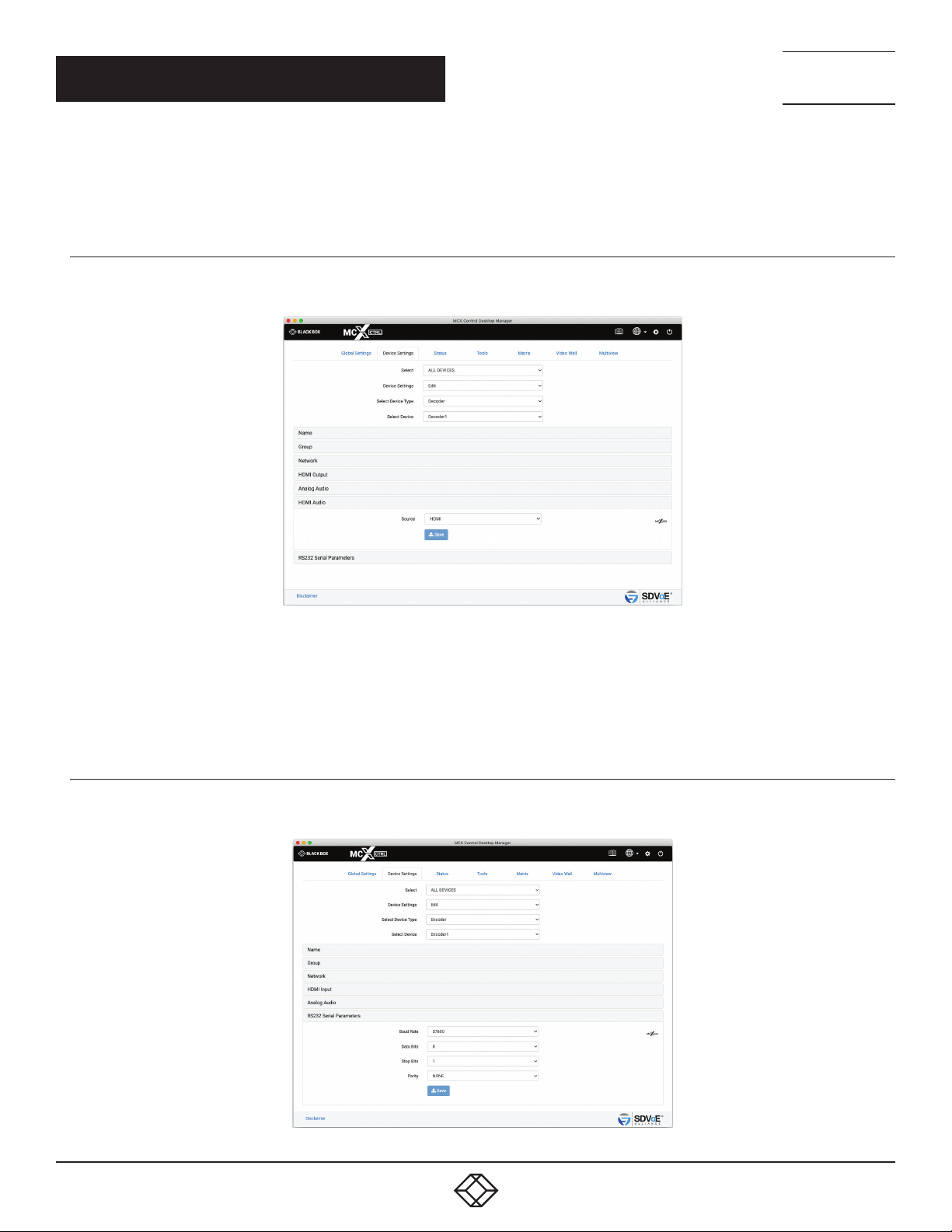
2.1.10 RS-232 SERIAL INTERFACE PAR AMETERS
Here you configure the parameters for the serial RS-232 port.
FIGURE 2-11.
48
FIGURE 2-12.
1. 8 77. 8 7 7. 2 2 69 BLACKBOX.COM
Page 49
NEED HELP?
LEAV E TH E TEC H TO US
LIVE 24/7
CHAPTER 2: DEVICE SETTINGS
TECHNICAL
SUPPORT
1. 8 7 7. 8 7 7. 2 2 69
1. Select Baud rate
2. Select Data Bits
3. Select Stop Bits
4. Select Parity
5. Click Save button
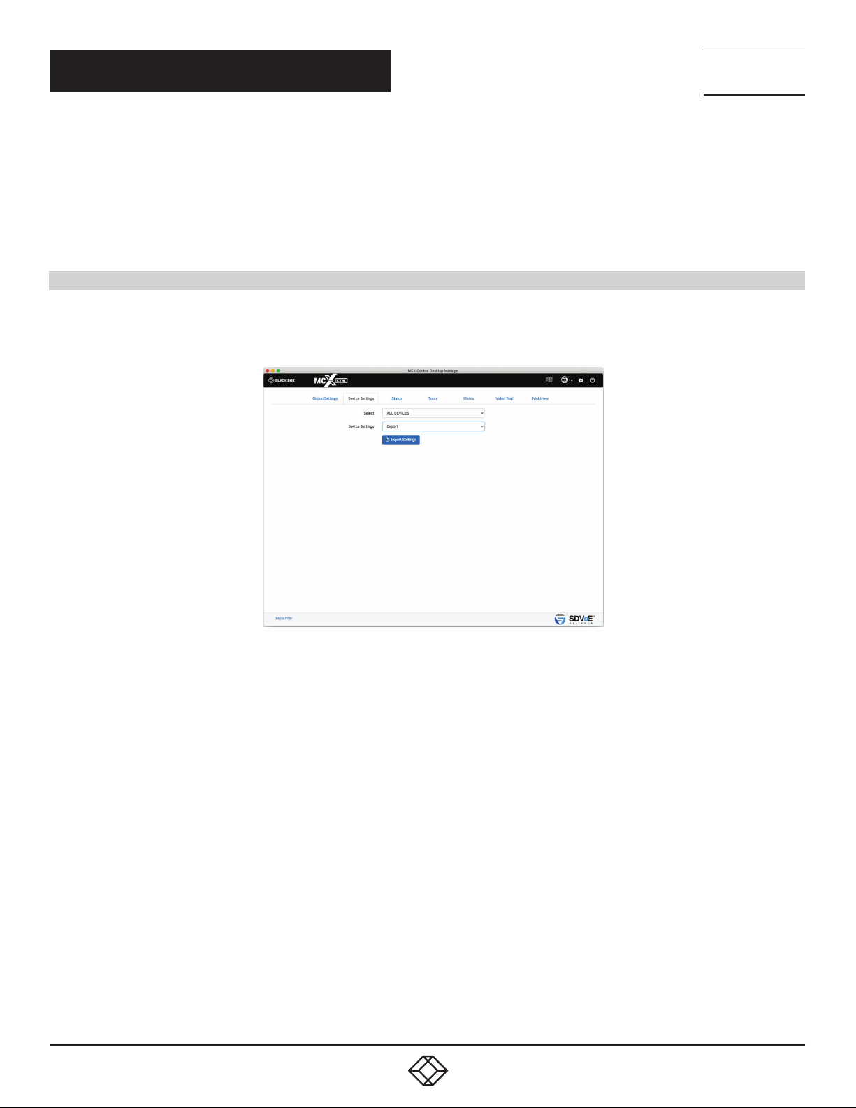
2.2 EXPORT SETTINGS
The current settings of all the Encoders and Decoders can be exported to a csv formatted file to be used as a configuration backup or be
used to reconfigure the Encoders and Decoders by changing the required data and importing it back into the MCX Network Management
Controller. A file named “DeviceExport.csv” will be exported to your Downloads folder.
1. Select Export
2. Click Export Settings button
FIGURE 2-13.
1. 8 77. 8 7 7. 2 2 69 BLACKBOX.COM
49
Page 50
NEED HELP?
LEAV E TH E TEC H TO US
LIVE 24/7
CHAPTER 2: DEVICE SETTINGS
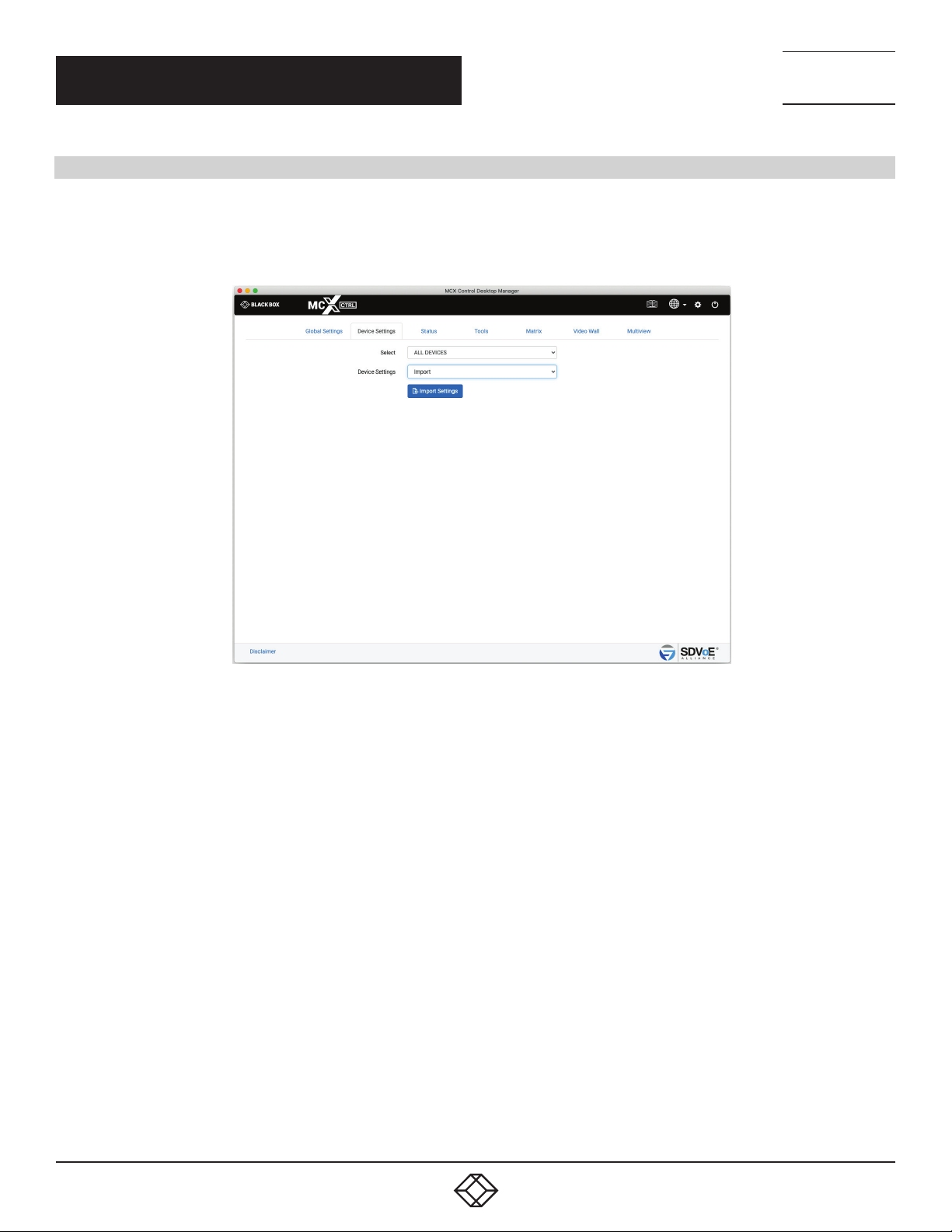
2.3 IMPORT SETTINGS
The exported device settings file can be imported back into the system from here. Any device configuration changes made to the
DeviceExport.csv will be applied once the file has been imported. This may take some time depending on the amount of configuration
changes that need to be performed.
TECHNICAL
SUPPORT
1. 8 7 7. 8 7 7. 2 2 69
1. Select Import
2. Click Import Data button
3. Select file
4. Click Open button
FIGURE 2-14.
50
1. 8 77. 8 7 7. 2 2 69 BLACKBOX.COM
Page 51
NEED HELP?
LEAV E TH E TEC H TO US
LIVE 24/7
CHAPTER 3: STATUS
TECHNICAL
SUPPORT
1. 8 7 7. 8 7 7. 2 2 69
3. S TAT US
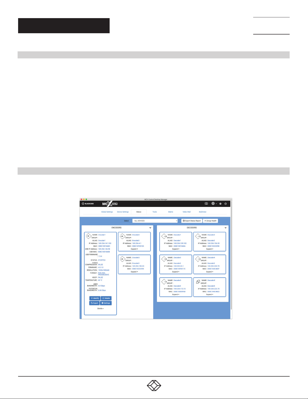
The Status tab contains information about how an Encoder or Decoder is currently functioning. Streams can also be stopped, started or
frame rates halved to manage bandwidth.
Encoders and Decoders can be filtered by groups to limit the number of devices being displayed.
The status of all Encoders and Decoders can be exported to a csv formatted file using the “Export Status Report” button located at the
top of the page. A StatusExport.csv file will be saved to your Downloads folder.
Icons are used to visually indicate the status of a device as follows:
Device is disconnected from the network.
Device is connected to the network, however, if the device is an Encoder it has no source, and if it is a Decoder it has no display
connected.
Encoder is online and has a source connected.
Decoder is online and has a display connected.
Device has a network issue and has timed out.
Device error
3.1 IDENTIFY
To help physically find a connected Encoder or Decoder in a rack type installation the LED’s on the front panel will flash for 30 seconds
after the Identify button has been clicked.
FIGURE 3-1.
Details contains information regarding the streams and subscriptions to those streams.
1. 8 77. 8 7 7. 2 2 69 BLACKBOX.COM
51
Page 52
NEED HELP?
LEAV E TH E TEC H TO US
LIVE 24/7
CHAPTER 3: STATUS
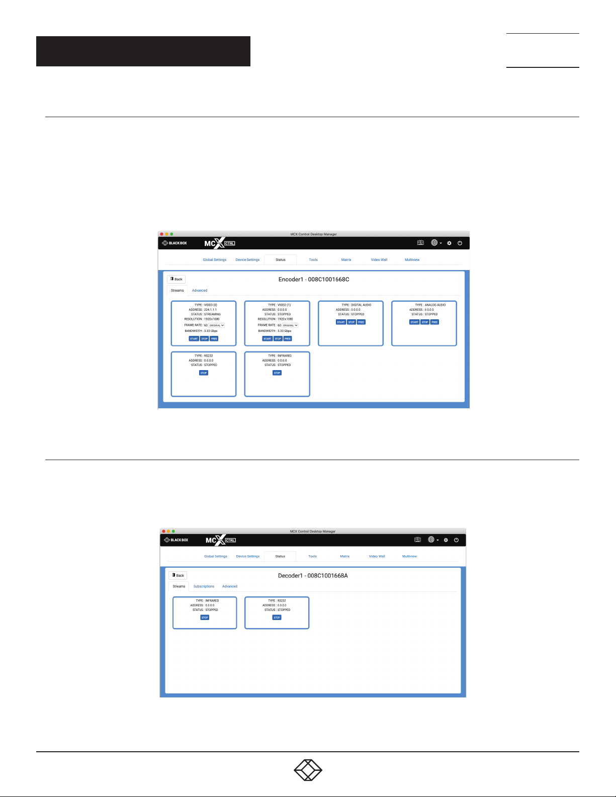
3.2.1 STREAMS (ENCODER)
The Streams tab of an Encoder will show the status of all streams along with their multicast address. The resolution, frame rate and
bandwidth of the video streams is also indicated.
From here you can stop or start any video/audio stream. The frame rate of progressive video signals can be set to the original or half the
original source frame rate.
When you free an Encoder stream, it will release its multicast address if working in multicast AUTO mode, and all connected Decoder
subscriptions will be cleared.
TECHNICAL
SUPPORT
1. 8 7 7. 8 7 7. 2 2 69
FIGURE 3-2.
3.2.2 STREAMS (DECODER)
The Streams tab of a Decoder will show the status of Infrared and RS-232 streams as these are the only streams sent from a Decoder.
From here you can stop either the Infrared or RS-232 streams.
FIGURE 3-3.
52
1. 8 77. 8 7 7. 2 2 69 BLACKBOX.COM
Page 53
NEED HELP?
LEAV E TH E TEC H TO US
LIVE 24/7
CHAPTER 3: STATUS
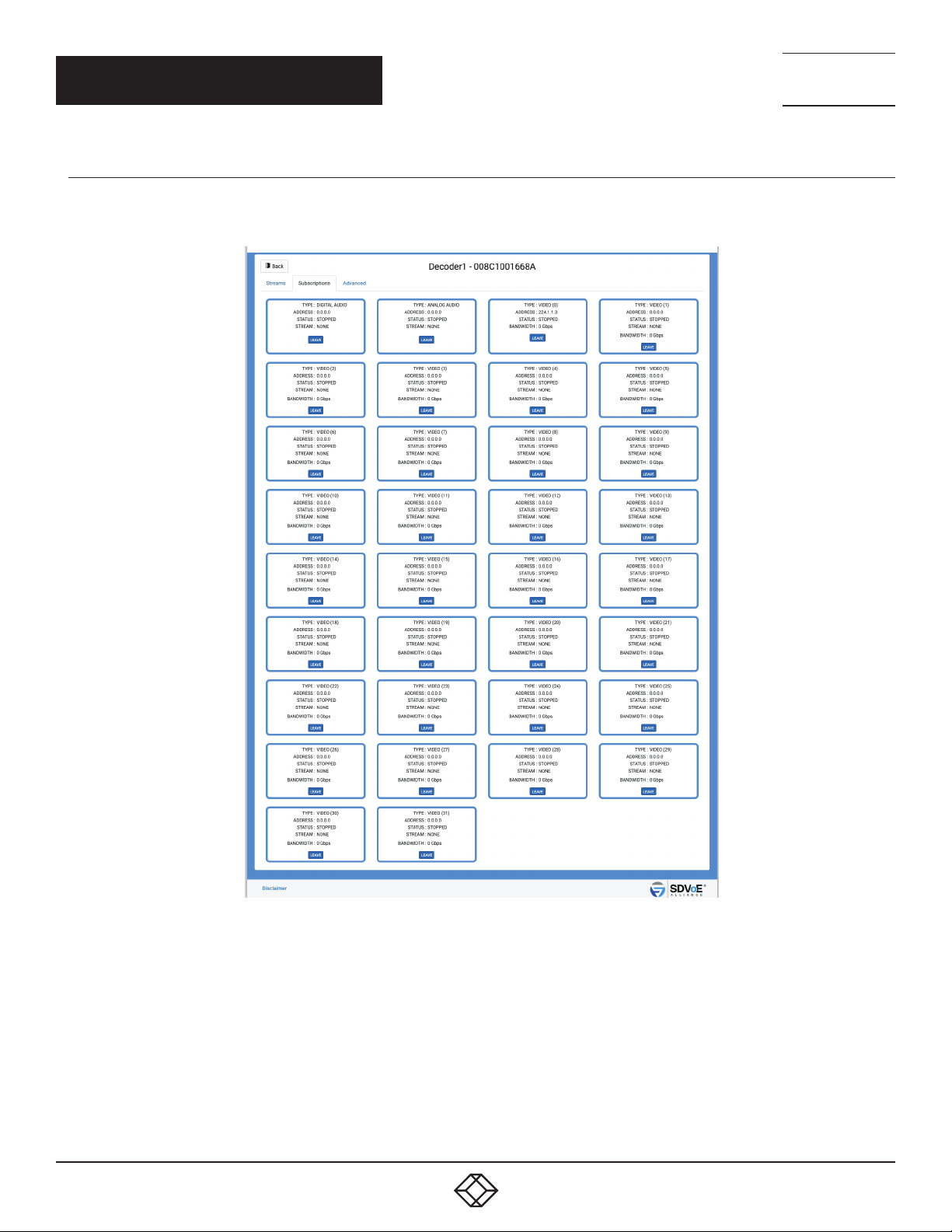
3.2.3 SUBSCRIPTIONS (DECODER)
The Subscriptions tab of a Decoder will show what multicast address is being used to receive data. It will also indicate from what
Encoder it is receiving the streams and the video streams bandwidth. From here you can leave any of the streams.
TECHNICAL
SUPPORT
1. 8 7 7. 8 7 7. 2 2 69
FIGURE 3-4.
1. 8 77. 8 7 7. 2 2 69 BLACKBOX.COM
53
Page 54
NEED HELP?
LEAV E TH E TEC H TO US
LIVE 24/7
CHAPTER 3: STATUS
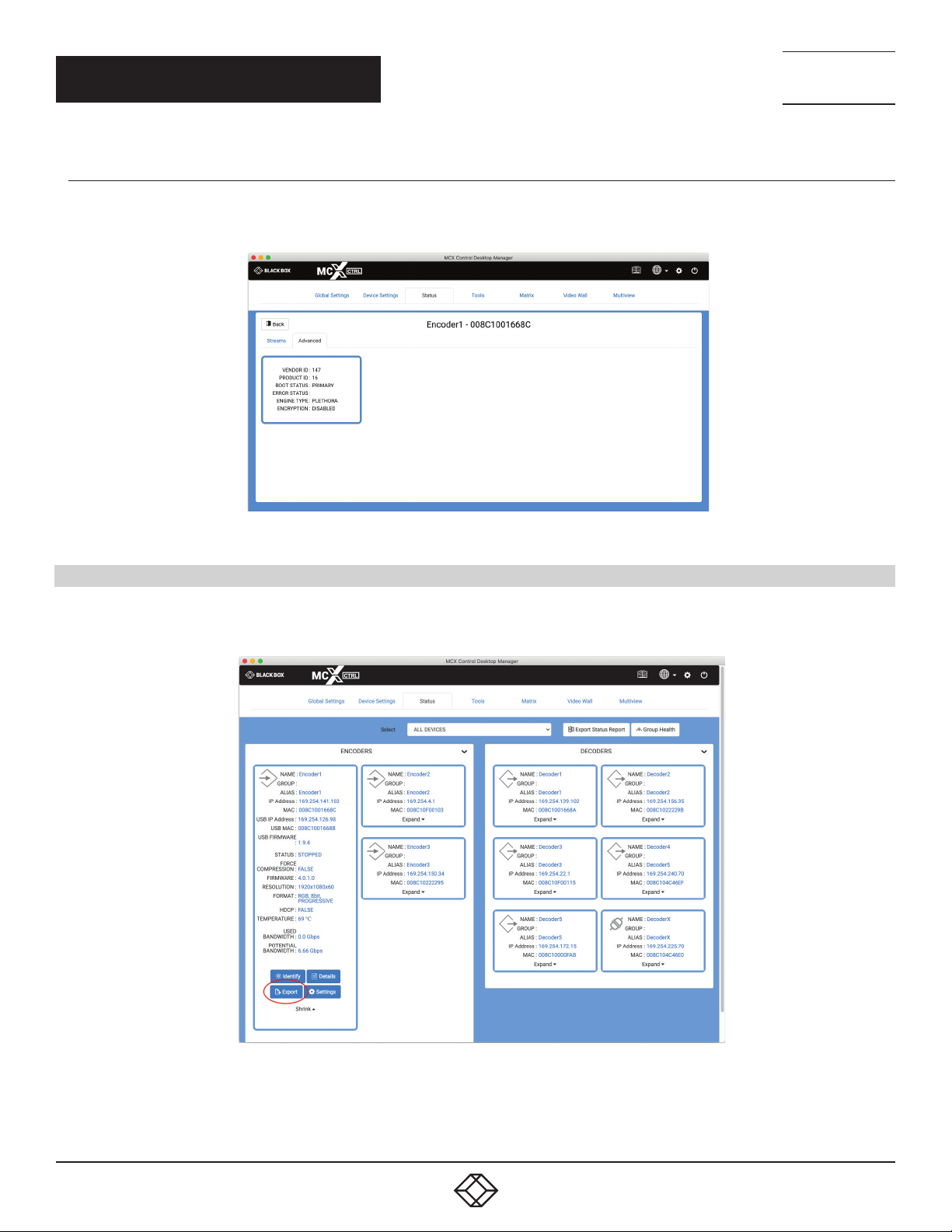
3.2.4 ADVANCED
The Advanced tab contains details of the device such as identification numbers, boot status along with the encryption status of the
device.
TECHNICAL
SUPPORT
1. 8 7 7. 8 7 7. 2 2 69
FIGURE 3-5.
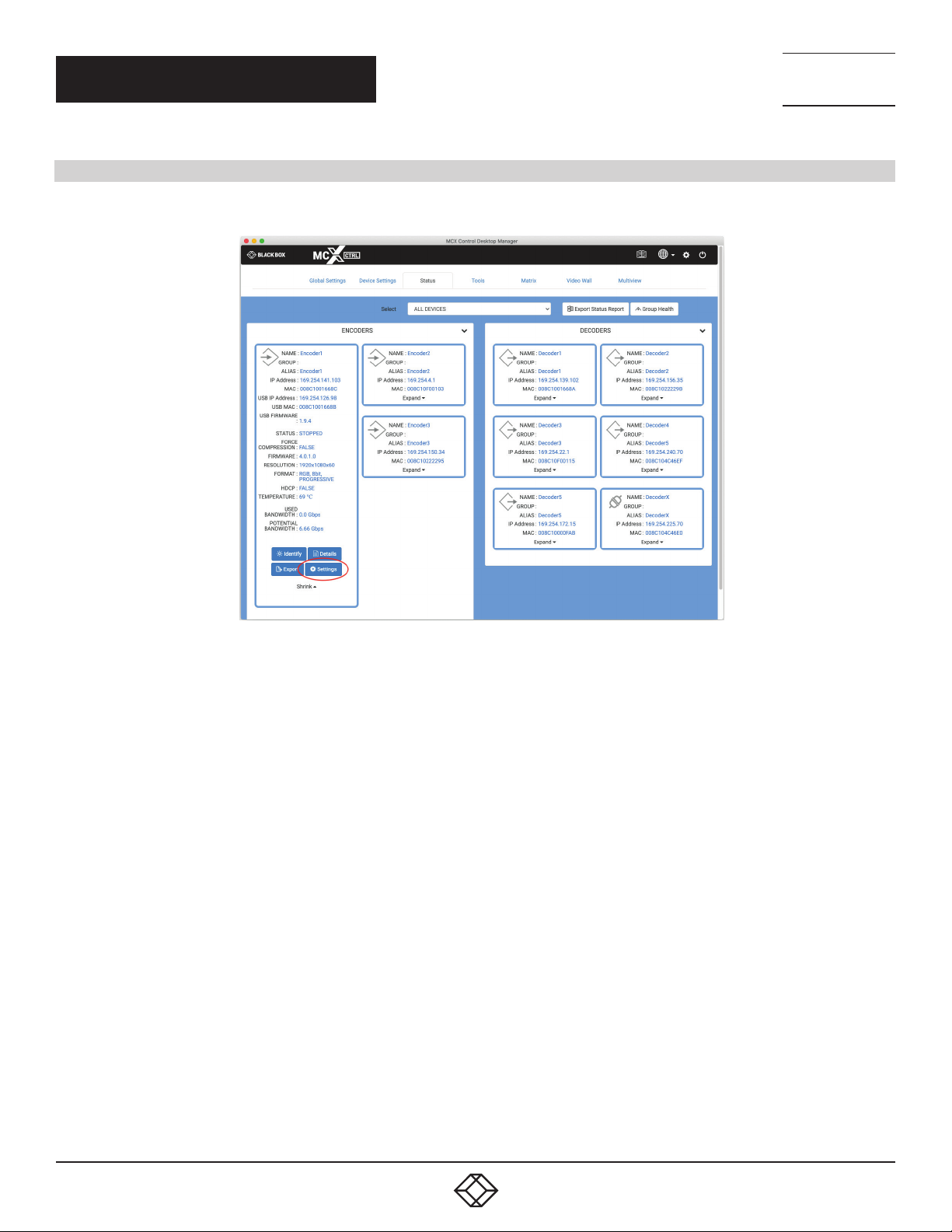
3.3 EXPORT
A JSON formatted file will export the complete status of the selected device. This is to be used for system diagnostics. A *.ini file with the
device name will be saved to your Downloads folder.
FIGURE 3-6.
Clicking the Settings button on a device will send you directly to the device settings tab.
54
1. 8 77. 8 7 7. 2 2 69 BLACKBOX.COM
Page 55
CHAPTER 3: STATUS
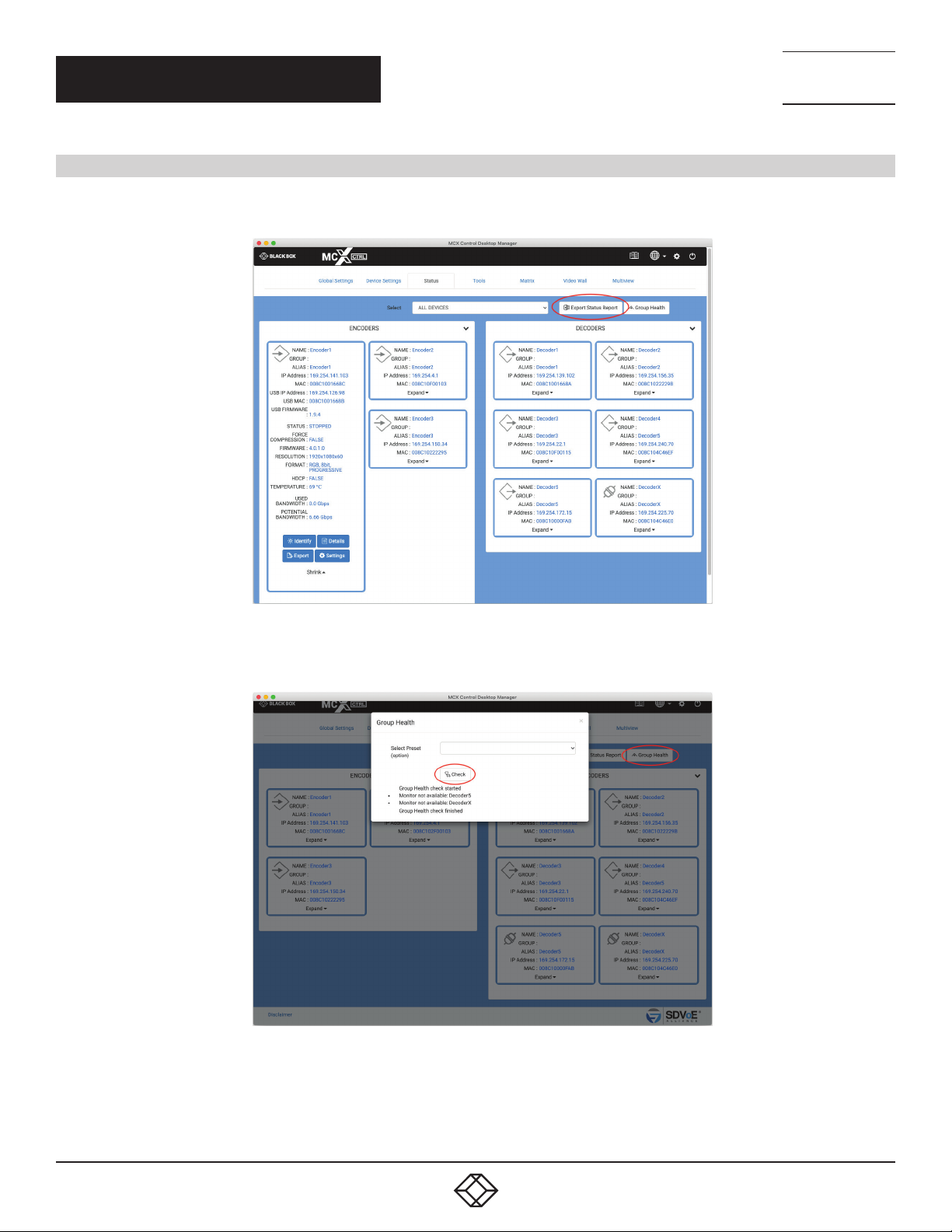
3.4 EXPORT STATUS REPORT
Export Status Report will save a csv formatted file with all the status details from this section.
NEED HELP?
LEAV E TH E TEC H TO US
LIVE 24/7
TECHNICAL
SUPPORT
1. 8 7 7. 8 7 7. 2 2 69
FIGURE 3-7.
1. 8 77. 8 7 7. 2 2 69 BLACKBOX.COM
55
Page 56
NEED HELP?
LEAV E TH E TEC H TO US
LIVE 24/7
CHAPTER 3: STATUS
3.5 GROUP HEALTH
Group Health will report the status of all the Encoders and Decoders in the selected group. If a group has a default preset associated with
it, this can also be selected and applied to make sure there are no issues before the system is put into use.
TECHNICAL
SUPPORT
1. 8 7 7. 8 7 7. 2 2 69
FIGURE 3-8.
FIGURE 3-9.
56
1. 8 77. 8 7 7. 2 2 69 BLACKBOX.COM
Page 57
CHAPTER 4: TOOLS
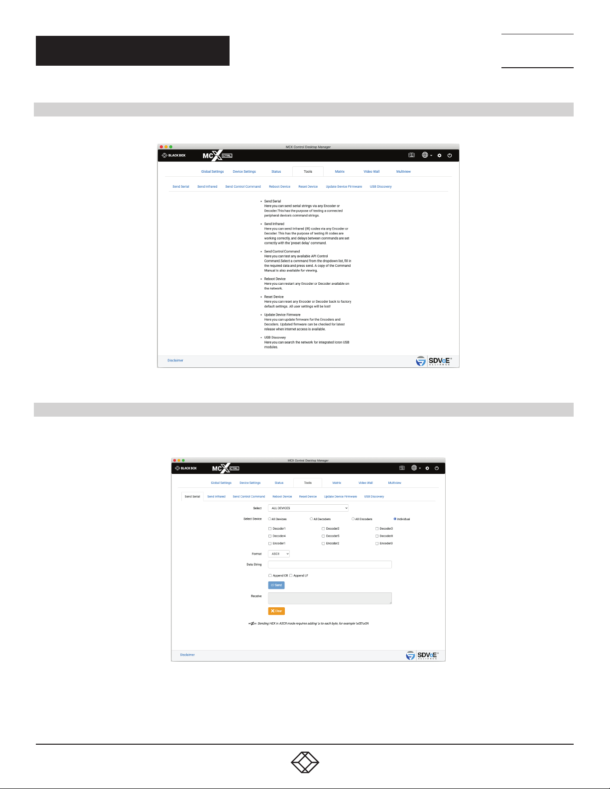
4. TOOLS
The Tools tab contains utilities to assist in the installation process and updating device firmware.
NEED HELP?
LEAV E TH E TEC H TO US
LIVE 24/7
TECHNICAL
SUPPORT
1. 8 7 7. 8 7 7. 2 2 69
FIGURE 4-1.
4.1 SEND SERIAL
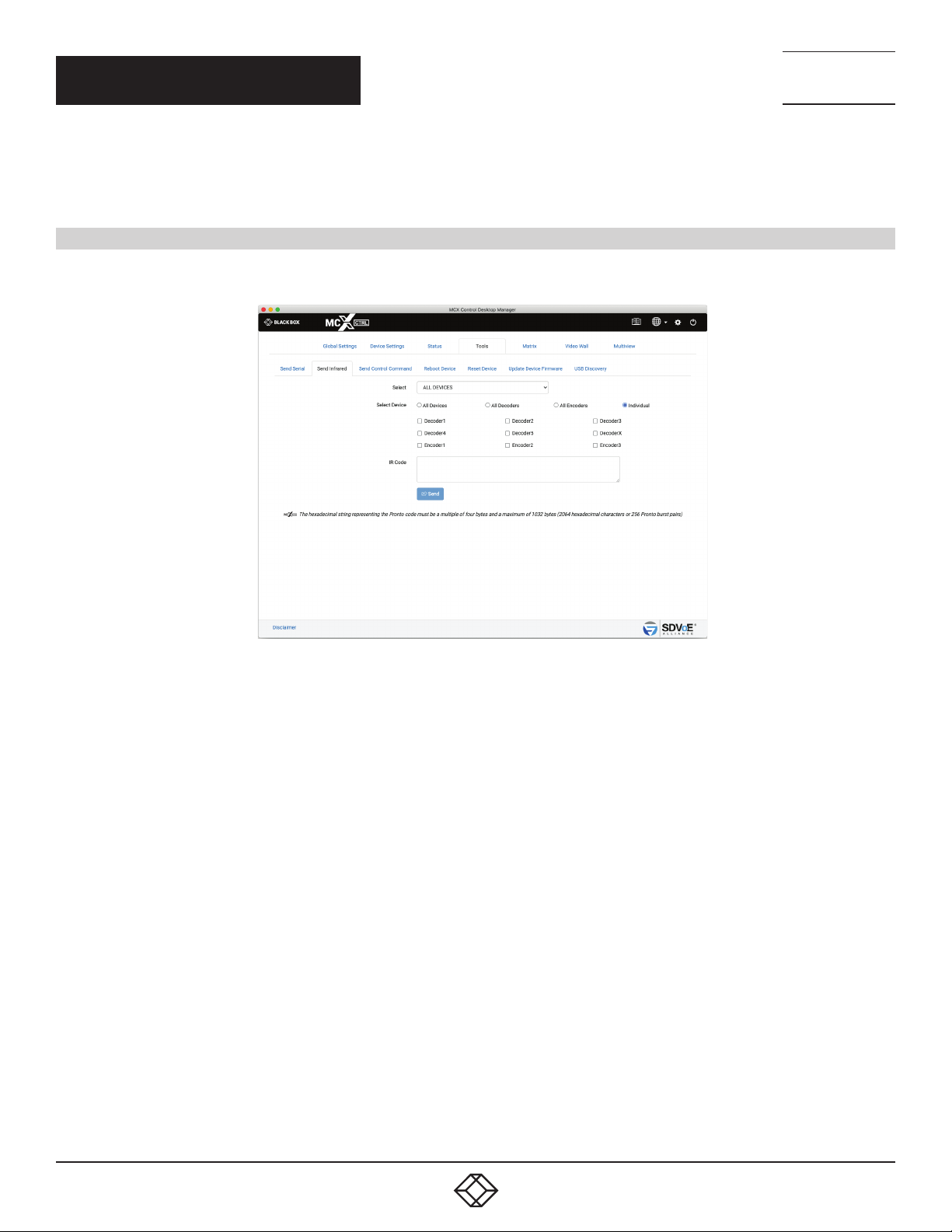
The Send Serial tab is used to test serial strings being sent from an Encoder or Decoder to 3rd party peripheral devices such as
projectors.
1. Select Device
2. Select either ASCII or HEX
3. Enter the Data String
FIGURE 4-2.
1. 8 77. 8 7 7. 2 2 69 BLACKBOX.COM
57
Page 58
NEED HELP?
LEAV E TH E TEC H TO US
LIVE 24/7
CHAPTER 4: TOOLS
4. Select a terminator if required
5. Click Send button
4.2 SEND INFRARED
The Send Infrared tab is used to test IR signals being sent from an Encoder or Decoder to 3rd party peripheral devices such as TV’s and
DVD players.
TECHNICAL
SUPPORT
1. 8 7 7. 8 7 7. 2 2 69
1. Select Device
2. Enter the IR Code to send
3. Click Send button
FIGURE 4-3.
58
1. 8 77. 8 7 7. 2 2 69 BLACKBOX.COM
Page 59
CHAPTER 4: TOOLS
4.3 SEND CONTROL COMMAND
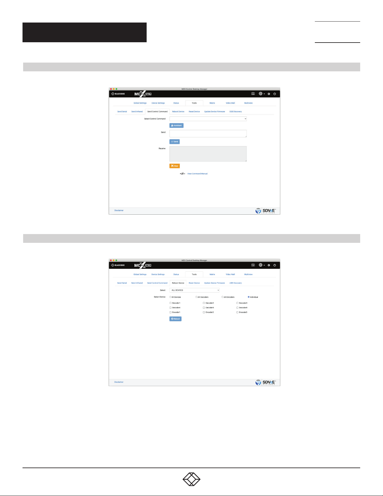
The Send Control Command is used to send any of the API commands available to the system for testing purposes.
NEED HELP?
LEAV E TH E TEC H TO US
LIVE 24/7
TECHNICAL
SUPPORT
1. 8 7 7. 8 7 7. 2 2 69
4.4 REBOOT DEVICE
The Reboot Device tab is used to reboot the selected device(s).
FIGURE 4-4.
FIGURE 4-5.
1. Select Device(s)
2. Click Reboot button
1. 8 77. 8 7 7. 2 2 69 BLACKBOX.COM
59
Page 60
CHAPTER 4: TOOLS
4.6 RESET DEVICE
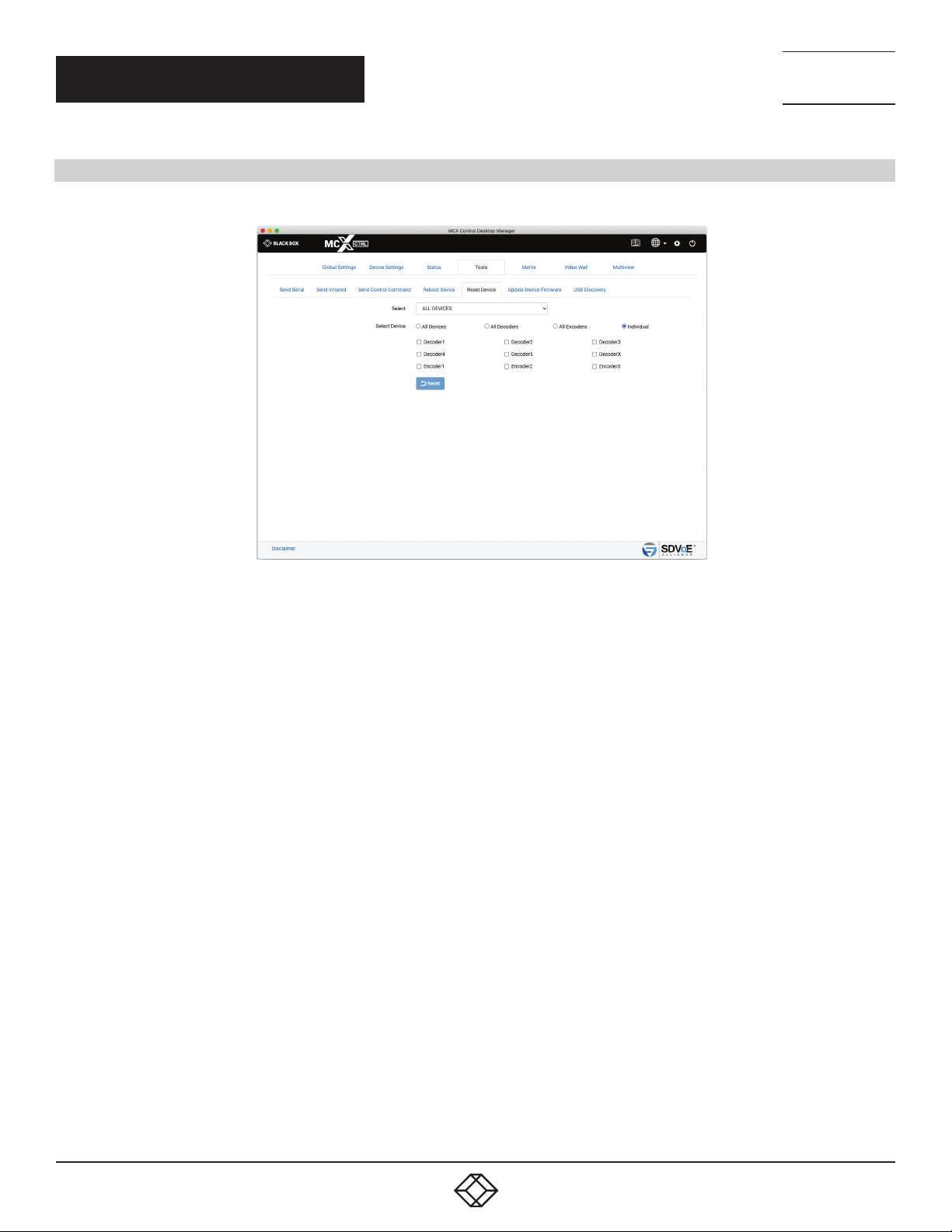
The Reset Device tab is used to reset the selected device(s) back to factory defaults.
NEED HELP?
LEAV E TH E TEC H TO US
LIVE 24/7
TECHNICAL
SUPPORT
1. 8 7 7. 8 7 7. 2 2 69
1. Select Device(s)
2. Click Reset button
FIGURE 4-6.
60
1. 8 77. 8 7 7. 2 2 69 BLACKBOX.COM
Page 61
NEED HELP?
LEAV E TH E TEC H TO US
LIVE 24/7
CHAPTER 4: TOOLS
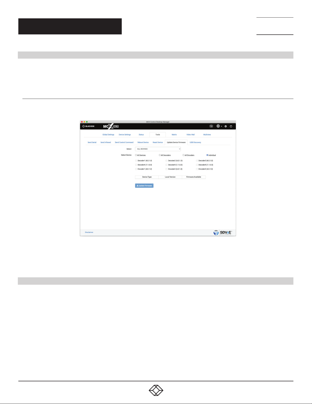
4.6 UPDATE DEVICE FIRMWARE
The Update Device Firmware tab is used to update the MCX or Icron USB firmware of Encoders and Decoders. Here you can also check
for updated MCX firmware from the internet when the MCX Network Management Controller has access. If a previous version of MCX
firmware is on the system then rolling back the device firmware is also possible.
4.6.1 UPDATE MCX FIRMWARE
MCX firmware is the device firmware for Encoders and Decoders.
TECHNICAL
SUPPORT
1. 8 7 7. 8 7 7. 2 2 69
FIGURE 4-7.
1. Select Device(s)
2. Click Update Firmware button
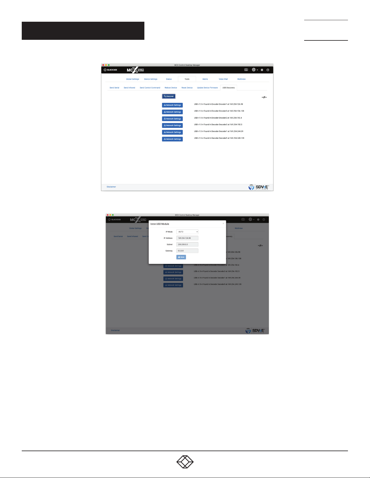
4.7 USB DISCOVERY
The USB Discovery tab is used to help find undiscovered USB modules that might be out of range from the rest of the system or have
incompatible firmware version. If the USB module has had a static IP applied then it will not respond when on a different subnet to the
MCX Network Management Controller (for example controller IP 169.254.1.1 and USB module IP 192.168.1.222). The MCX Network
Management Controllers IP will need to be set to the same range as the USB module before it can be found.
* Icron USB modules must have at least version 1.8.5 firmware to be compatible with this system.
1. 8 77. 8 7 7. 2 2 69 BLACKBOX.COM
61
Page 62
CHAPTER 4: TOOLS
NEED HELP?
LEAV E TH E TEC H TO US
LIVE 24/7
TECHNICAL
SUPPORT
1. 8 7 7. 8 7 7. 2 2 69
1. Click Discover button
2. Click a Network button to show network
FIGURE 4-8.
FIGURE 4-9.
62
1. 8 77. 8 7 7. 2 2 69 BLACKBOX.COM
Page 63
NEED HELP?
LEAV E TH E TEC H TO US
LIVE 24/7
CHAPTER 5: MATRIX
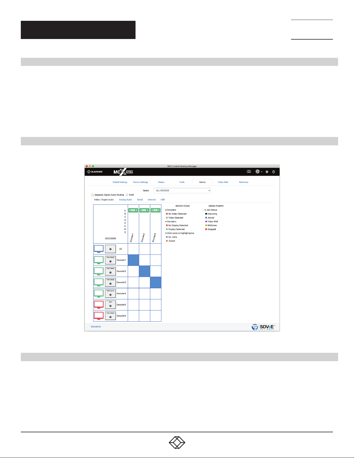
5. MATRIX
The Matrix tab contains up to 6 individual matrix tabs for each of the signal types, Video, Digital Audio, Analog Audio, Serial, Infrared and
USB. Here you can create or stop joins between Encoders and Decoders. The video modes of NT2000 Decoders can also be changed by
clicking the individual Decoder settings buttons.
The matrix has a KVM (Keyboard Video Mouse) checkbox that will control USB along with Video routing. When Separate Digital Audio
Routing is not selected, Digital Audio will also follow the Video routing.
Click a white square to make a join.
Click a blue square to remove a join.
5.1 VIDEO/DIGITAL AUDIO
Here the Video and Digital Audio are combined so they are both joined to the destination device.
TECHNICAL
SUPPORT
1. 8 7 7. 8 7 7. 2 2 69
FIGURE 5-1.
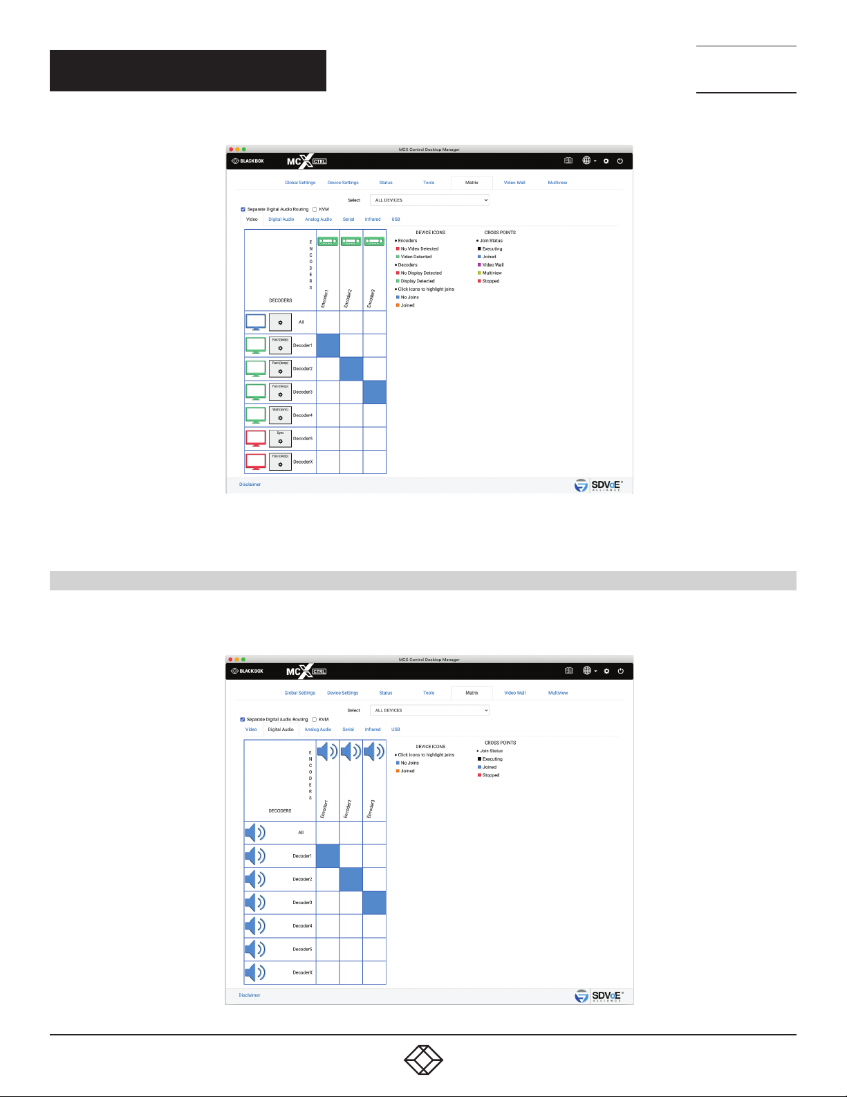
5.2 VIDEO
When independent routing of the Video and Digital Audio is required, select the Separate Digital Audio Routing checkbox. Now the Video
and Digital Audio will appear in separate independent matrix tabs.
1. 8 77. 8 7 7. 2 2 69 BLACKBOX.COM
63
Page 64
CHAPTER 5: MATRIX
NEED HELP?
LEAV E TH E TEC H TO US
LIVE 24/7
TECHNICAL
SUPPORT
1. 8 7 7. 8 7 7. 2 2 69
FIGURE 5-2.
5.3 DIGITAL AUDIO
When independent routing of the Video and Digital Audio is required select the Separate Digital Audio Routing checkbox. Now the Video
and Digital Audio will appear in separate independent matrix tabs.
64
FIGURE 5-3.
1. 8 77. 8 7 7. 2 2 69 BLACKBOX.COM
Page 65
CHAPTER 5: MATRIX
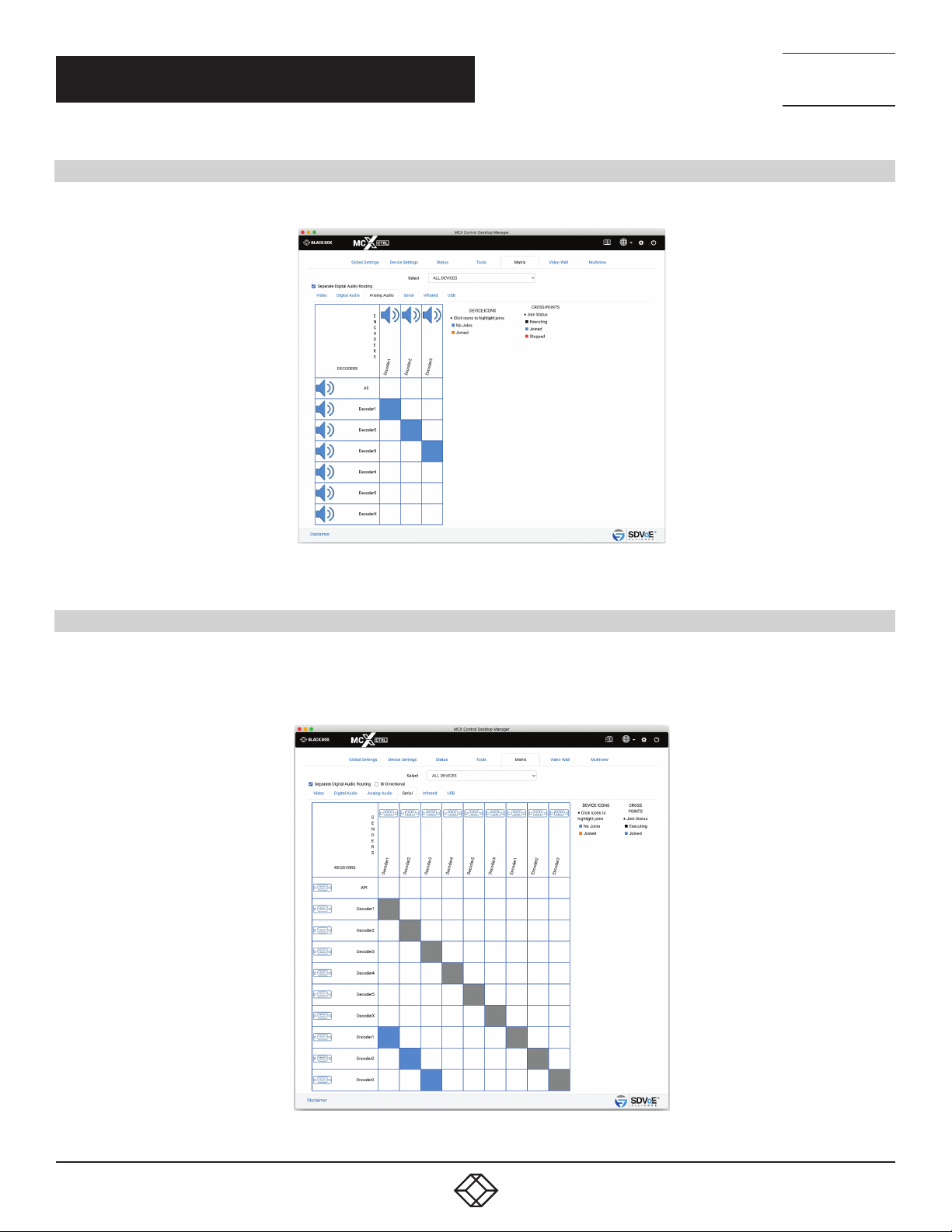
5.4 ANALOG AUDIO
The matrix Analog Audio tab is intended for making analog audio joins between Encoders and Decoders.
NEED HELP?
LEAV E TH E TEC H TO US
LIVE 24/7
TECHNICAL
SUPPORT
1. 8 7 7. 8 7 7. 2 2 69
FIGURE 5-4.
5.5 SERIAL
The matrix Serial tab is intended for making serial joins between Encoders and Decoders. Serial joins work on a one way principle in that
the RX of the sender device is connected to the TX of the receiver device. This only creates a 1-way connection. For a 2-way (Bi-Direction)
connection select the Bi-Directional checkbox before making joins.
FIGURE 5-5.
1. 8 77. 8 7 7. 2 2 69 BLACKBOX.COM
65
Page 66
NEED HELP?
LEAV E TH E TEC H TO US
LIVE 24/7
CHAPTER 5: MATRIX
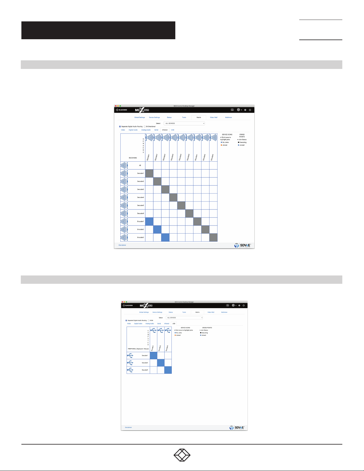
5.6 INFRARED
The matrix Infrared tab is intended for making infrared joins between Encoders and Decoders. Infrared joins work on a one-way
principle in that the sender device is connected to the receiver device. This only creates a 1-way connection. For a 2-way (Bi-Directional)
connection select the Bi-Directional checkbox before making joins.
TECHNICAL
SUPPORT
1. 8 7 7. 8 7 7. 2 2 69
FIGURE 5-6.
5.7 U S B
The matrix USB tab will only show Encoders and Decoders with USB installed and correctly configured.
66
FIGURE 5-7.
1. 8 77. 8 7 7. 2 2 69 BLACKBOX.COM
Page 67
NEED HELP?
LEAV E TH E TEC H TO US
LIVE 24/7
CHAPTER 6: VIDEO WALL
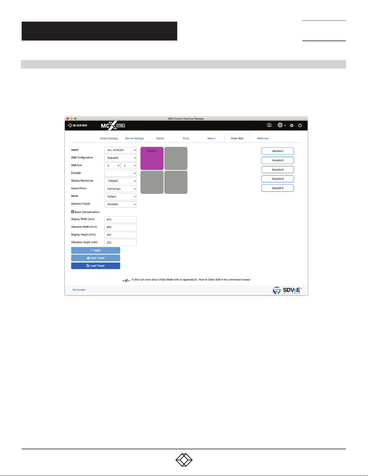
6. VIDEO WALL
Video Wall configuration has two modes of operation, standard and advanced.
Standard mode has simple bezel compensation when a uniform bezel size is used so only the display width and viewable width are
required to calculate the required bezel compensation.
Advanced mode has various types of bezel compensation and can be used to specify individual monitor bezel sizes.
TECHNICAL
SUPPORT
1. 8 7 7. 8 7 7. 2 2 69
FIGURE 6-1.
1. 8 77. 8 7 7. 2 2 69 BLACKBOX.COM
67
Page 68
CHAPTER 6: VIDEO WALL
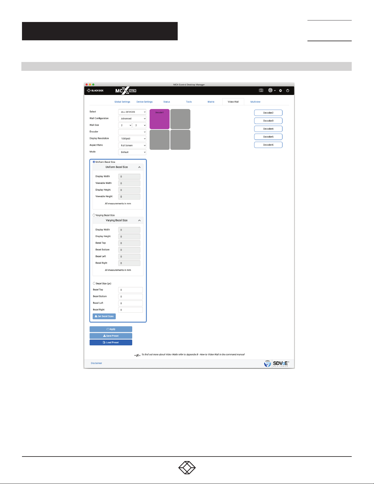
6.1 VIDEO WALL STANDARD
NEED HELP?
LEAV E TH E TEC H TO US
LIVE 24/7
TECHNICAL
SUPPORT
1. 8 7 7. 8 7 7. 2 2 69
1. Select the group of Encoders and Decoders to be available.
2. Select a Group to be shown
3. Select Configuration Standard
4. Select layout
5. Select source
6. Select Display Resolution
68
FIGURE 6-2.
1. 8 77. 8 7 7. 2 2 69 BLACKBOX.COM
Page 69

NEED HELP?
LEAV E TH E TEC H TO US
LIVE 24/7
CHAPTER 6: VIDEO WALL
TECHNICAL
SUPPORT
1. 8 7 7. 8 7 7. 2 2 69
7. Select Aspect Ratio
8. Select switching Mode
9. Select Dynamic Preset
9.1 Select Compensation
9.2 Enter display width Enter viewable width
9.3 Enter display height Enter viewable height
10. Drag displays to position
10.1 Save or Apply the layout
10.2 Drag display to position
10.3 Drag display to position
11. Drag display to position
12. Drag display to position
12.1 Select either Standard or Advanced mode, in this case Standard Advanced mode provides more options for Bezel Compensation
12.2 Select the video wall layout up to 8 x 5
12.3 Select the source Encoder for the video to be displayed Only Encoders with an active source will be shown
12.4 Select the resolution of the displays The cropped video area from the original source content will be scaled to a display resolution.
So if the cropped area is only 960x540, in this case it will be scaled to 1920x1080 for the display.
13. Select Aspect Ratio. Either select Full Screen or Maintain Aspect Ratio. Full Screen may stretch the video image to fill the display
area while Maintain Aspect Ratio will add black to the sides and top and bottom of the displayed image to maintain the original video
aspect ratio.
14. Select switching Mode Normal (Sync) or Fast. (Device firmware > 3.5.2.0 and MCX firmware > 2.14.0 required)
15. Enable or Disable Dynamic Preset. When Enabled the preset will be applied on a change of source resolution to reapply the correct
crop settings for the new resolution.
16. Select Bezel Compensation to automatically compensate for the bezel widths (Standard mode assumes a constant display bezel
size)
17. Enter the physical width of the display in mm Enter the physical viewable width of the display in mm
18. Drag Decoders / Displays to the correct wall position
19. Save or apply the layout. The layout can be saved as a preset to be recalled via the “preset load”
1. 8 77. 8 7 7. 2 2 69 BLACKBOX.COM
69
Page 70
CHAPTER 6: VIDEO WALL
6.2 VIDEO WALL ADVANCED
NEED HELP?
LEAV E TH E TEC H TO US
LIVE 24/7
TECHNICAL
SUPPORT
1. 8 7 7. 8 7 7. 2 2 69
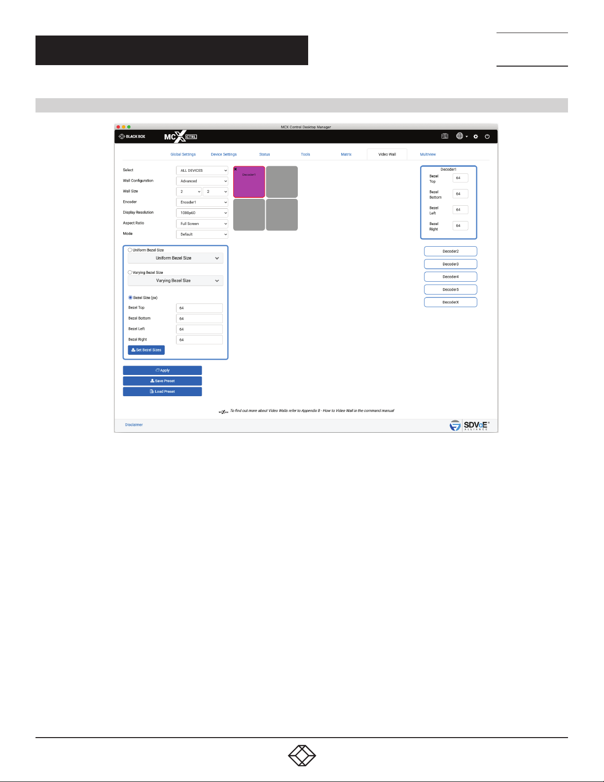
FIGURE 6-3.
1. Select a Group to be shown
2. Select Configuration Advanced
3. Select layout
4. Select source
5. Select resolution
6. Select Aspect Ratio
7. Select switching Mode
8.1. Select Compensation method
8.2. Enter required sizes for selected method
9. Click Set Bezel Sizes button
10. Drag display to position
11. Save or Apply the preset
12. Select the group of Encoders and Decoders to be available.
13. Select either Stand or Advanced modes, in this case Advanced (Advanced mode provides more options for Bezel Compensation).
14. Select the video wall layout up to 8 x 5.
15. Select the source Encoder for the video to be displayed. Only Encoders with an active source will be shown.
70
1. 8 77. 8 7 7. 2 2 69 BLACKBOX.COM
Page 71

NEED HELP?
LEAV E TH E TEC H TO US
LIVE 24/7
CHAPTER 6: VIDEO WALL
16. Select the resolution of the displays The cropped video area from the original source content will be scaled to a display resolution. So
if the cropped area is only 960x540, in this case will be scaled to 1920x1080 for the display.
17. Select Aspect Ratio. Either select Full Screen or Maintain Aspect Ratio. Full Screen may stretch the video image to fill the display
area while Maintain Aspect Ratio will add black to the sides and top and bottom of the displayed image to maintain the original video
aspect ratio.
18. Select switching Mode Normal (Sync) or Fast.
19. Select Bezel Compensation method to automatically compensate for the bezel widths.
Uniform Bezel Size is used when the display has a constant bezel size.
Varying Bezel Size is used when the display has different bezel sizes.
Bezel Size (px) is used when you manually want to specify the pixel compensation, otherwise this area will show the resulting pixel
compensation calculated from the physical dimension of the display from either Uniform Bezel Size or Varying Bezel Size calculations.
TECHNICAL
SUPPORT
1. 8 7 7. 8 7 7. 2 2 69
Uniform Bezel Size
Enter the physical width of the display in mm.
Enter the physical viewable width of the display in mm.
Varying Bezel Size
8.2. Enter the physical width of the display in mm.
Enter the physical height of the display in mm.
Enter the top physical bezel width of the display in mm.
Enter the bottom physical bezel width of the display in mm.
Enter the left physical bezel width of the display in mm.
Enter the bottom physical bezel width of the display in mm.
Bezel Size (px)
8.2. Enter the top bezel compensation in pixels.
Enter the bottom bezel compensation in pixels.
Enter the left bezel compensation in pixels.
Enter the right bezel compensation in pixels.
9. Load the Bezel Compensation values to the displays. If no displays are selected at this stage, then all will be populated with the values.
Individual displays can be selected to load the values which is useful when different display types are used in the layout, or when
varying bezel sized monitors are rotated within the layout.
10. Drag Decoders/Displays to the correct wall position.
11. Save or apply the layout. The layout can be saved as a preset to be recalled via the “preset load” command or loaded back into the UI.
1. 8 77. 8 7 7. 2 2 69 BLACKBOX.COM
71
Page 72

NEED HELP?
LEAV E TH E TEC H TO US
LIVE 24/7
CHAPTER 6: VIDEO WALL
In advanced mode, each individual display of the video wall can have separate bezel compensation applied when using a mix of display
types. Click the display position and the displays bezel compensation window will popup. Here you can change the bezel sizes as
required.
TECHNICAL
SUPPORT
1. 8 7 7. 8 7 7. 2 2 69
72
1. 8 77. 8 7 7. 2 2 69 BLACKBOX.COM
Page 73
NEED HELP?
LEAV E TH E TEC H TO US
LIVE 24/7
CHAPTER 7: MULTIVIEW
7. M U LT I VI E W
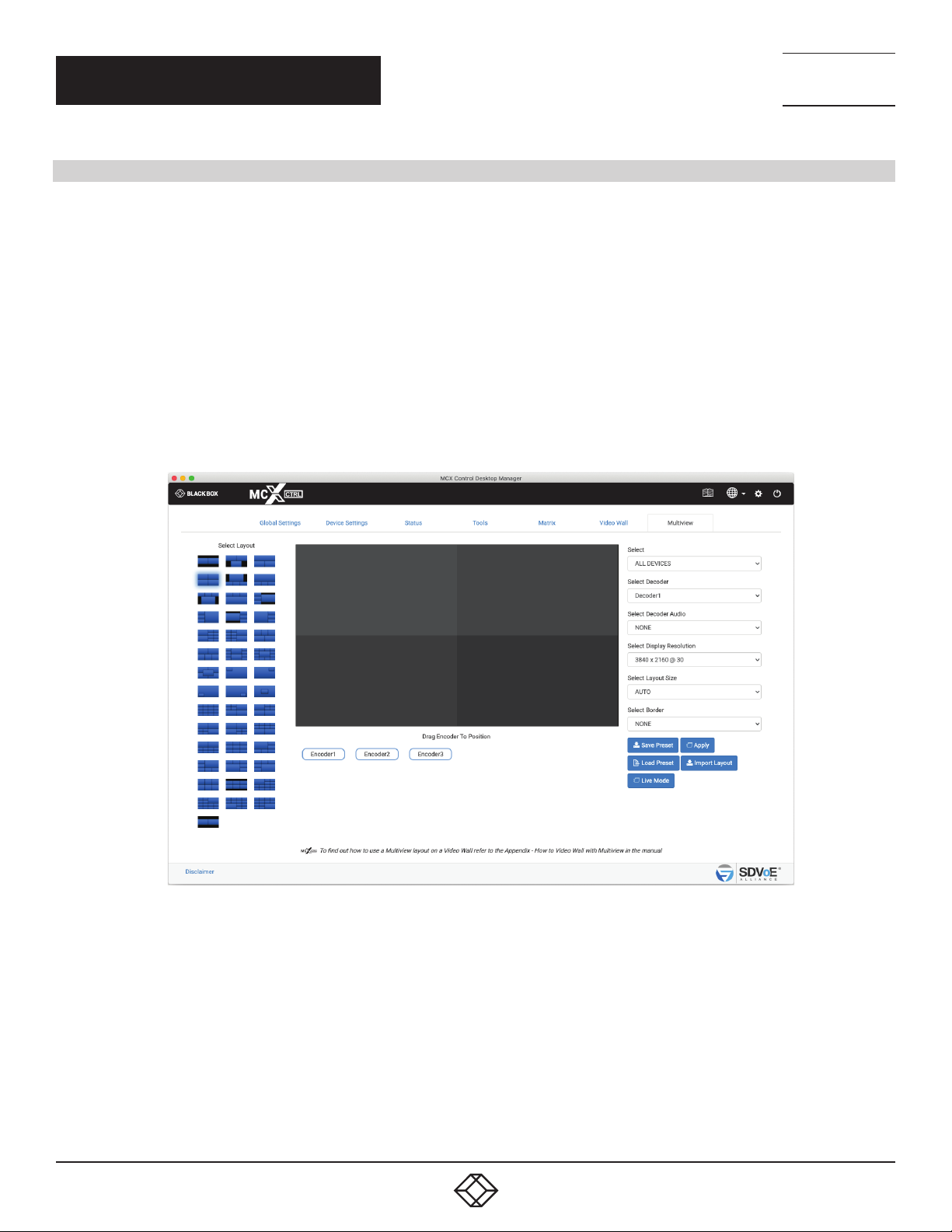
The Multiview function has a lot of bandwidth considerations to take into account if both Encoder video streams are working. Keep in
mind that an Encoder has two separate video streams. Stream 0 is the main stream used for normal video switching. This stream will
automatically be slightly compressed with all streams greater than 9 Gbps. Stream 1 is a dedicated RGB stream that can be scaled for
use with Multiview. This stream is NOT compressed and is therefore limited to 30 Hz refresh rates. In some cases, stream 0 itself can
use all the available bandwidth leaving no room for stream 1 on the network. In these cases, the software can perform a few functions to
maintain a total Encoder bandwidth less than 9 Gbps.
Both stream 0 and stream 1 are set to half frame rate for PROGRESSIVE signals over 30 Hz.
Stream 0 may be used instead of stream 1 if the source video resolution matches the window size.
Stream 0 may be turned off completely if not enough bandwidth is available for stream 1.
The layout size will automatically be reduced to 1920 x 1080 when an Encoder with an INTERLACED source > 30 Hz is dropped on a
window larger than 2,073,600 pixels when the layout size has been set for 3840 x 2160. This is because the frame rate of an INTERLACED
signal cannot be reduced so the bandwidth must be managed by reducing the video size.
TECHNICAL
SUPPORT
1. 8 7 7. 8 7 7. 2 2 69
FIGURE 7-1.
1. 8 77. 8 7 7. 2 2 69 BLACKBOX.COM
73
Page 74
CHAPTER 7: MULTIVIEW
7.1 MULTIVIEW LAYOUT
NEED HELP?
LEAV E TH E TEC H TO US
LIVE 24/7
TECHNICAL
SUPPORT
1. 8 7 7. 8 7 7. 2 2 69
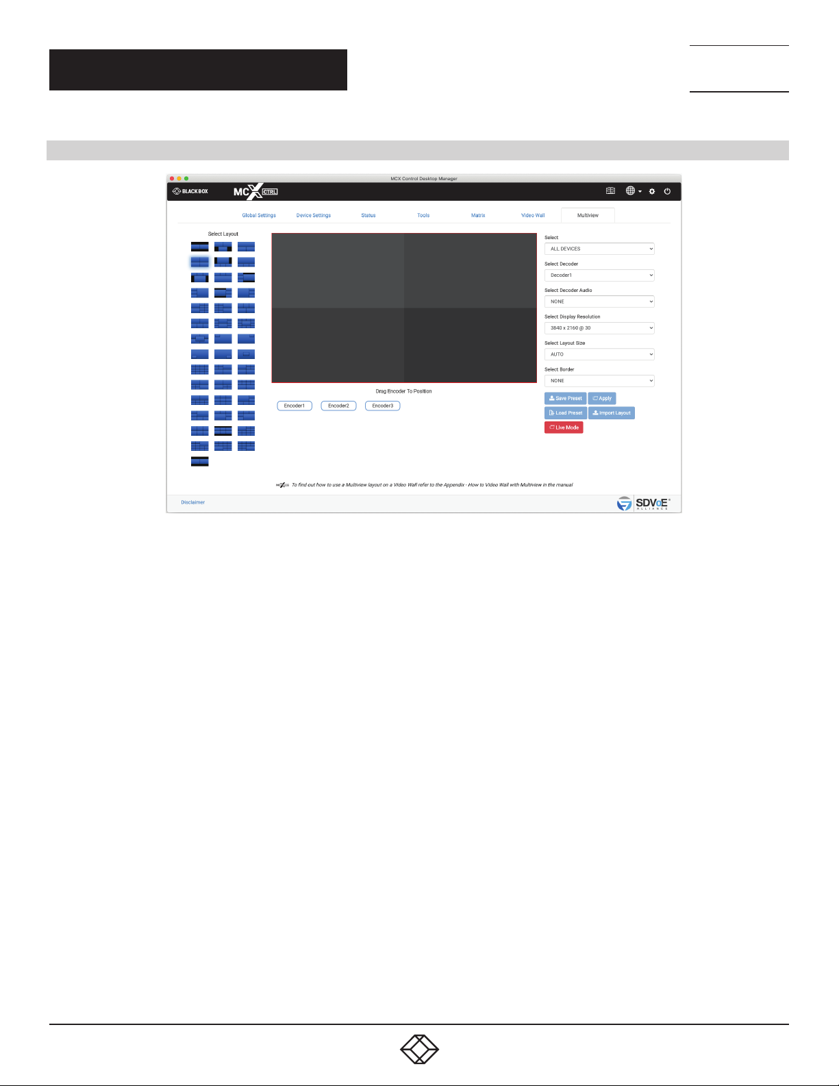
FIGURE 7-2.
1. Select 1 of the 42 predefined layouts.
2. Select the group of Encoders and Decoders to be available.
3. Select the required Decoder to display the layout.
4. Select Decoder Audio by selecting either None or an Encoder.
5. Select the display resolution as either AUTO, 3840 x 2160 @ 30, 3840 x 2160 @ 60, 1920 x 1080 @ 60 or Custom.
AUTO will use the displays preferred resolution from the EDID.
Display resolution is independent of layout size. The Decoder will scale the output resolution to the display. So this is the
resolution the layout will be shown. A 1920 x 1080 layout can be shown at 3840 x 2160 and a 3840x2160 layout can be shown as
1920 x 1080.
6. Select the layout size of AUTO, 3840 x 2160 or 1920 x 1080 (AUTO will use the Display Resolution)
Let’s look at the example shown of a 2 x 2 layout.
If the layout size was 3840 x 2160 then each window is sized 1920x1080. So the resolution of the Encoder streams will be scaled
to 1920 x 1080.
If the layout size was 1920 x 1080 then each window is sized 960 x 540. So the resolution of the Encoder streams will be scaled
to 960 x 540. Which in turn only uses half the network bandwidth.
7. Select default border or none.
8. Drag the required Encoder/Source to desired window location. Only same-sized windows can use the same duplicated Encoder/
Source.
74
1. 8 77. 8 7 7. 2 2 69 BLACKBOX.COM
Page 75
NEED HELP?
LEAV E TH E TEC H TO US
LIVE 24/7
CHAPTER 7: MULTIVIEW
9. Save or apply the layout. The layout can be saved as a preset to be recalled via the “preset load” command or loaded back into the UI.
TECHNICAL
SUPPORT
1. 8 7 7. 8 7 7. 2 2 69
FIGURE 7-3.
7.2 MULTIVIEW LIVE
1. Use the “Live Mode” button to toggle the function on/off.
2. Drag sources to window locations or remove sources from windows.
Live mode will provide an instant change to the sources applied to a layout. Live mode is automatically disabled when changing layouts
or any of the dropdown options.
7.3 MULTIVIEW LAYOUT IMPORT
Custom Multiview layouts are available on request. The supplied custom layout file can be imported here into the system and will be
added to the displayed available layouts. (Keep in mind that any layout is achievable using direct API commands or editing an existing
preset.)
1. Click Import Layout button
2. Select layout file
3. Click Open button
1. 8 77. 8 7 7. 2 2 69 BLACKBOX.COM
75
Page 76

NEED HELP?
LEAV E TH E TEC H TO US
LIVE 24/7
CHAPTER 7: MULTIVIEW
7.4 MULTIVIEW PRESETS
Multiview presets created and saved from the UI contain optional commands and logic that are present to manage system bandwidth
and to provide a clean viewable experience. These optional commands and logic blocks can be removed or replaced with constant
commands for known system conditions.
Here is an example of the code generated from the 1st UI multiview layout:
Define a new layout
layout new MV _ e1 3840 2160
Define layout windows
layout window MV _ e1 0 0 540 1920 1080 0
layout window MV _ e1 1 1920 540 1920 1080 1
Clear all previous Decoder subscriptions (optional)
leave all Decoder2
TECHNICAL
SUPPORT
1. 8 7 7. 8 7 7. 2 2 69
Turn on video mute to blank the display until all the video streams are joined (optional)
set video _ mute Decoder2 true 000000
To reduce Encoder1 bandwidth workout if the main hdmi:0 stream can have half frame rate applied or if the original frame rate needs to
be restored (optional)
if(get video Encoder1 sm == PROGRESSIVE)
{ if(get video Encoder1 fps > 30){ if not(get frame _ converter Encoder1 main){
set frame _ converter Encoder1 main true
}
}else{
if(get frame _ converter Encoder1 main){
set frame _ converter Encoder1 main false
}
}
}
76
1. 8 77. 8 7 7. 2 2 69 BLACKBOX.COM
Page 77

NEED HELP?
LEAV E TH E TEC H TO US
LIVE 24/7
CHAPTER 7: MULTIVIEW
TECHNICAL
SUPPORT
1. 8 7 7. 8 7 7. 2 2 69
To reduce Encoder2 bandwidth workout if the main hdmi:0 stream can have half frame rate applied or if the original frame rate needs to
be restored (optional)
if(get video Encoder2 sm == PROGRESSIVE){
if(get video Encoder2 fps > 30){
if not(get frame _ converter Encoder2){
set frame _ converter Encoder2 main true
}
}else{
if(get frame _ converter Encoder2){
set frame _ converter Encoder2 main false
}
}
}
Set the Decoder to multiview mode with the required display resolution
multiview Decoder2 MV _ e1 3840 2160 30
To reduce bandwidth from Encoder1 workout if we can use the main hdmi:0 stream instead of the sub stream hdmi:1 (optional,
otherwise keep “join multi Encoder1 Decoder1 0 scaled MV_e1”)
if(get video Encoder1 width == get window MV _ e1 0 width){
if(get video Encoder1 height == get window MV _ e1 0 height){
if(get video Encoder1 sm == PROGRESSIVE){
if(get video Encoder1 bpp == 8){ if(get video Encoder1 cs == YCBCR _ 420){
join multi Encoder1 Decoder1 0 scaled MV _ e1 }
else{
join multi Encoder1 Decoder1 0
stop sub Encoder1
}
}else{
join multi Encoder1 Decoder1 0 scaled MV _ e1
}
}else{
join multi Encoder1 Decoder1 0 scaled MV _ e1
}
}else{
join multi Encoder1 Decoder1 0 scaled MV _ e1
}
}else{
join multi Encoder1 Decoder1 0 scaled MV _ e1 }
1. 8 77. 8 7 7. 2 2 69 BLACKBOX.COM
77
Page 78

NEED HELP?
LEAV E TH E TEC H TO US
LIVE 24/7
CHAPTER 7: MULTIVIEW
To reduce bandwidth from Encoder1 workout if we can use the main hdmi:0 stream instead of the sub stream hdmi:1 (optional,
otherwise keep “join multi Encoder2 Decoder1 1 scaled MV_e1”)
if(get video Encoder2 width == get window MV _ e1 1 width){
if(get video Encoder2 height == get window MV _ e1 1 height){
if(get video Encoder2 sm == PROGRESSIVE){
if(get video Encoder2 bpp == 8){
if(get video Encoder2 cs == YCBCR _ 420){
join multi Encoder2 Decoder1 1 scaled MV _ e1
}else{
join multi Encoder2 Decoder1 1
stop sub Encoder2
}
}else{
join multi Encoder2 Decoder1 1 scaled MV _ e1
}
}else{
join multi Encoder2 Decoder1 1 scaled MV _ e1
}
}else{
join multi Encoder2 Decoder1 1 scaled MV _ e1
}
}else{
join multi Encoder2 Decoder1 1 scaled MV _ e1
}
TECHNICAL
SUPPORT
1. 8 7 7. 8 7 7. 2 2 69
Check Encoder1 bandwidth is not exceeding 9 Gbps and turn off the main stream hdmi:0 if required (optional)
if(get status Encoder1 video 1 == STREAMING){
if(get bandwidth Encoder1 > 9){
stop video Encoder1
}
}
Check Encoder2 bandwidth is not exceeding 9 Gbps and turn off the main stream hdmi:0 if required (optional)
if(get status Encoder2 video 1 == STREAMING){
if(get bandwidth Encoder2 > 9){
stop video Encoder2
}
}
78
1. 8 77. 8 7 7. 2 2 69 BLACKBOX.COM
Page 79

NEED HELP?
LEAV E TH E TEC H TO US
LIVE 24/7
CHAPTER 7: MULTIVIEW
TECHNICAL
SUPPORT
1. 8 7 7. 8 7 7. 2 2 69
Turn off the Decoder video mute so the multiview can now be displayed (optional)
set video _ mute Decoder2 false
Remove any audio from the multiview Decoder (optional)
leave audio _ d Decoder2
Here is the layout with all the optional commands and logic blocks removed. This would be a minimalistic approach to a multiview
preset.
Define a new layout
layout new MV _ e1 3840 2160
Define layout windows
layout window MV _ e1 0 0 540 1920 1080 0
layout window MV _ e1 1 1920 540 1920 1080 1
Set the Decoder to multiview mode with the required display resolution
multiview Decoder2 MV_e1 3840 2160 30
Join Encoder1 to multiview window 0
join multi Encoder1 Decoder1 0 scaled MV _ e1
Join Encoder2 to multiview window 1
join multi Encoder2 Decoder1 1 scaled MV _ e1
1. 8 77. 8 7 7. 2 2 69 BLACKBOX.COM
79
Page 80
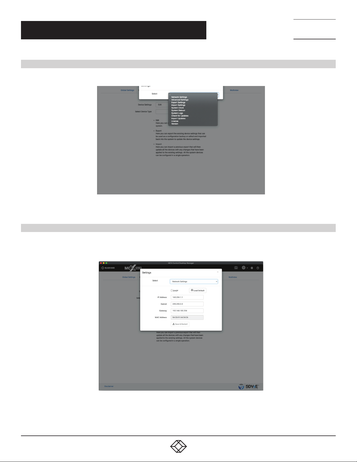
CHAPTER 8: SYSTEM SETTINGS
8. SYSTEM SE TTINGS
All the system level settings can be accessed by admin level users by clicking the gear icon on the top of the page.
NEED HELP?
LEAV E TH E TEC H TO US
LIVE 24/7
TECHNICAL
SUPPORT
1. 8 7 7. 8 7 7. 2 2 69
FIGURE 8-1.
8.1 NETWORK SETTINGS
Here you can change the IP configuration of the MCX Network Management Controller. This address must be set in the same range as
the Encoders and Decoders. By default the MCX Network Management Controller will be found at 169.254.1.1. Use the Finder if unable to
locate the controller on the network.
80
FIGURE 8-2.
1. 8 77. 8 7 7. 2 2 69 BLACKBOX.COM
Page 81
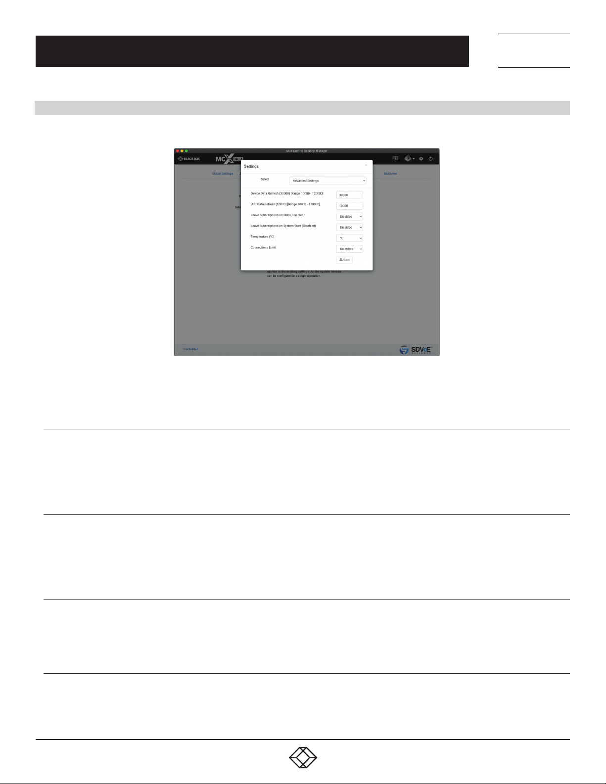
CHAPTER 8: SYSTEM SETTINGS
8.2 ADVANCED SETTINGS
The Advanced Settings section contains the settings of the MCX Network Management Controller.
NEED HELP?
LEAV E TH E TEC H TO US
LIVE 24/7
TECHNICAL
SUPPORT
1. 8 7 7. 8 7 7. 2 2 69
FIGURE 8-3.
8.2.1 DEVICE DATA REFRESH
Device Data Refresh is the time in milliseconds the MCX Network Management Controller requests information about the Encoders
and Decoders. This keeps the UI up-to-date with any changes that have occurred that do not cause an event which would automatically
update data. The default is 30000 = 30 seconds with a range of 10000 – 120000.
8.2.2 USB DATA REFRESH
USB Data Refresh is the time in milliseconds the MCX Network Management Controller requests information about the Encoder’s and
Decoder’s USB. This keeps the UI up-to-date with any changes that have occurred that don’t cause an event which would automatically
update data. The default is 10000 = 10 seconds with a range of 10000 – 120000.
8.2.3 LEAVE SUBSCRIPTIONS ON STOP
Leave Subscriptions on Stop is an optional condition of the system whereby all Decoders will leave their subscription to a stream when
the Encoder’s stream is stopped. The default is disabled.
8.2.4 LEAVE SUBSCRIPTIONS ON SYSTEM START
Leave Subscriptions on system start is an optional condition of the system whereby all Decoders will leave their subscription to a stream
when the system starts. The default is disabled.
1. 8 77. 8 7 7. 2 2 69 BLACKBOX.COM
81
Page 82
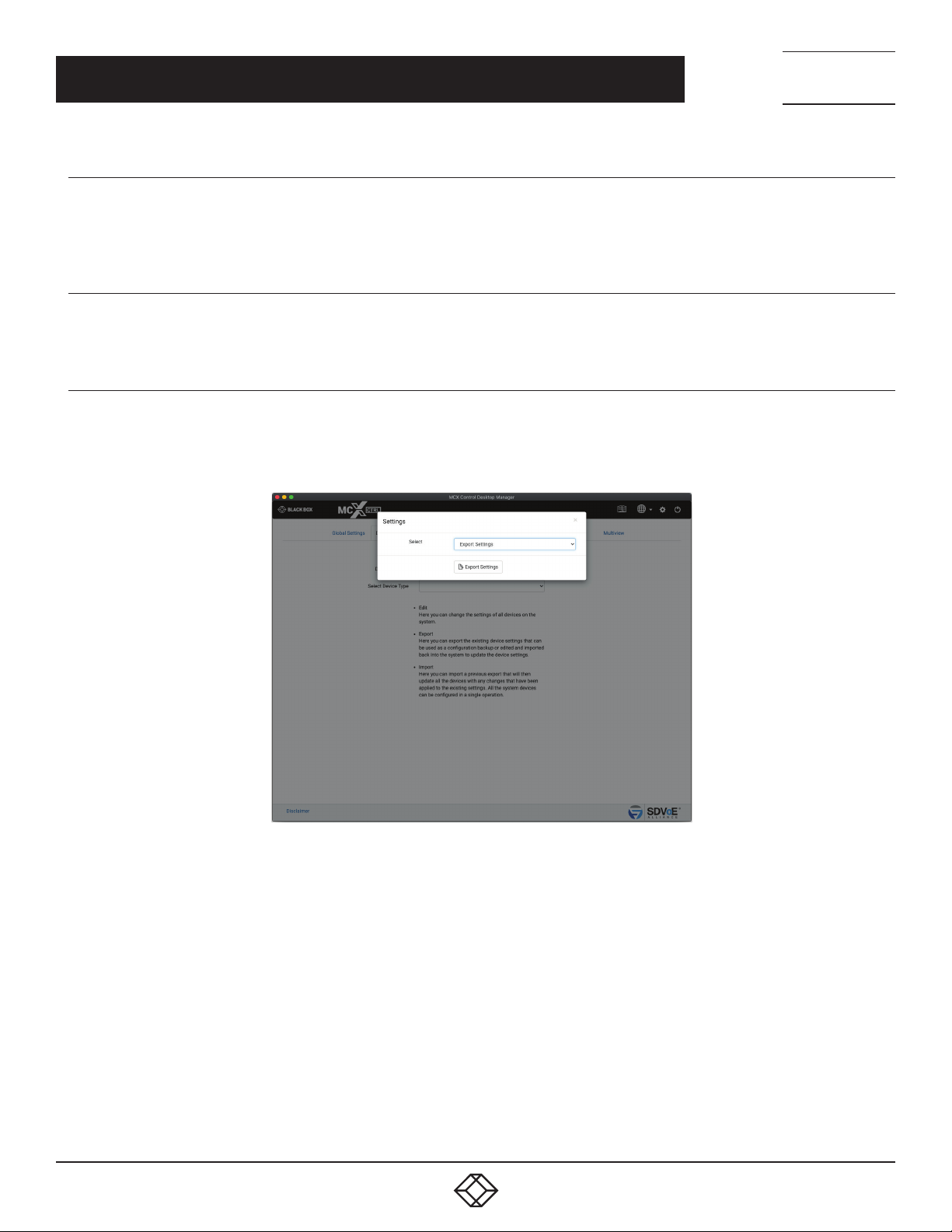
NEED HELP?
LEAV E TH E TEC H TO US
LIVE 24/7
CHAPTER 8: SYSTEM SETTINGS
8.2.5 TEMPERATURE
Here you can select the system to display temperature of the Encoders and Decoders in either Celsius (°C) or Fahrenheit (°F). The default
is Celsius (°C).
8.2.6 CONNECTIONS LIMIT
Here you can set the number of simultaneous connections to the TCP control port 6980 to unlimited or from 1 to 10 connections.
8.3 EXPORT SETTINGS
Export Settings will save a file named UIsettings.exp to your Downloads folder. This file contains all the settings of the MCX Network
Management Controller. Use this exported file as a configuration backup that can be imported back into the system to restore the current
configuration.
TECHNICAL
SUPPORT
1. 8 7 7. 8 7 7. 2 2 69
82
FIGURE 8-4.
1. 8 77. 8 7 7. 2 2 69 BLACKBOX.COM
Page 83
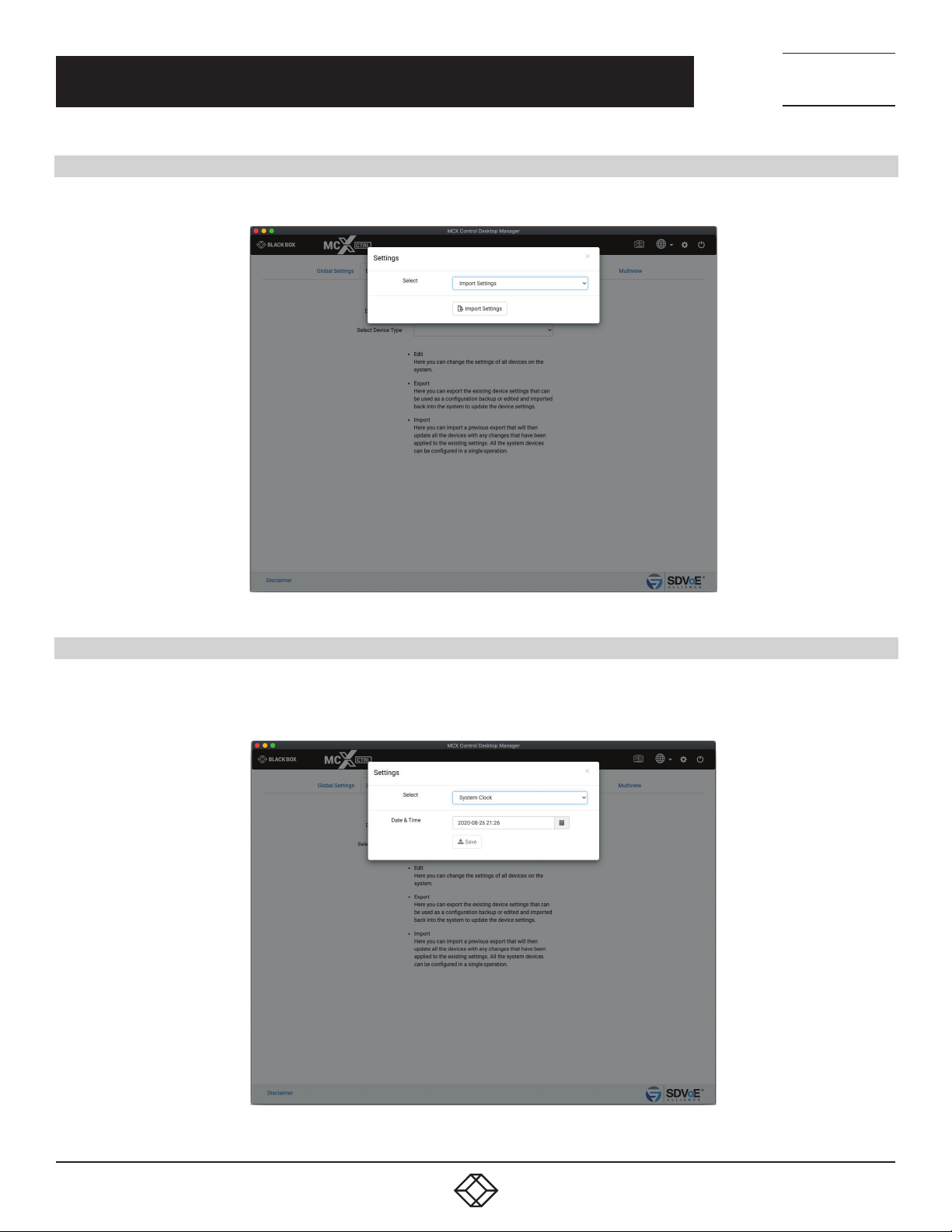
NEED HELP?
LEAV E TH E TEC H TO US
LIVE 24/7
CHAPTER 8: SYSTEM SETTINGS
8.4 IMPORT SETTINGS
Use Import Settings to load an exported UIsettings.exp file which will restore the MCX Network Management Controllers settings.
TECHNICAL
SUPPORT
1. 8 7 7. 8 7 7. 2 2 69
FIGURE 8-5.
8.5 SYSTEM CLOCK
The MCX Network Management Controller contains a RTC (Real Time Clock) to maintain the correct time and date. Set your local time
and date here and click the Save button to apply the changes. The system clock is used for the scheduler and also time stamping the log
entries.
FIGURE 8-6.
1. 8 77. 8 7 7. 2 2 69 BLACKBOX.COM
83
Page 84
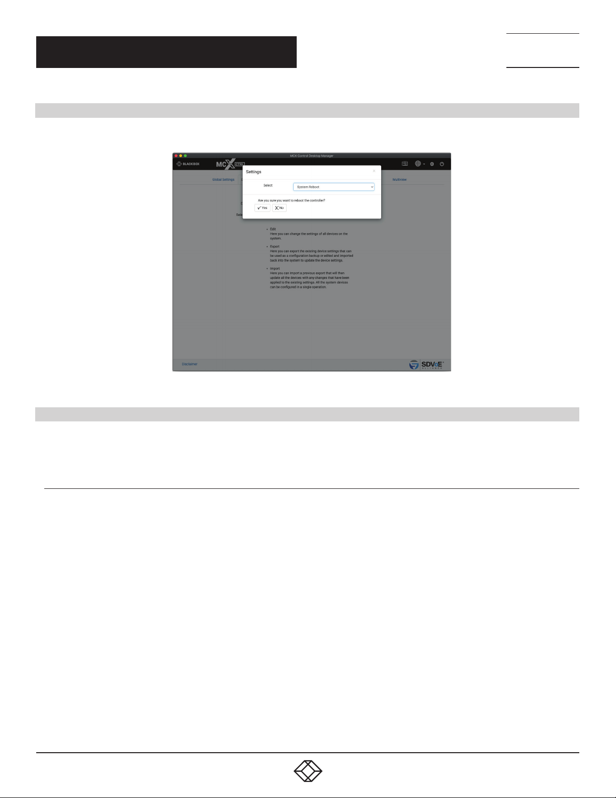
CHAPTER 8: SYSTEM SETTINGS
8.6 SYSTEM REBOOT
Here you can reboot the MCX Network Management Controller. It takes 60 seconds for the controller to Reboot.
NEED HELP?
LEAV E TH E TEC H TO US
LIVE 24/7
TECHNICAL
SUPPORT
1. 8 7 7. 8 7 7. 2 2 69
FIGURE 8-7.
8.7 SYSTEM LOGS
The system keeps three (3) different log files, MCX, Software & USB. Select the required log from the dropdown list. Click the save button
to export the selected log. A file named *.exp will be saved to your Downloads folder. This file has zip compression.
8.7.1 M C X L OG
An MCX Log contains all the MCX logged information.
84
1. 8 77. 8 7 7. 2 2 69 BLACKBOX.COM
Page 85
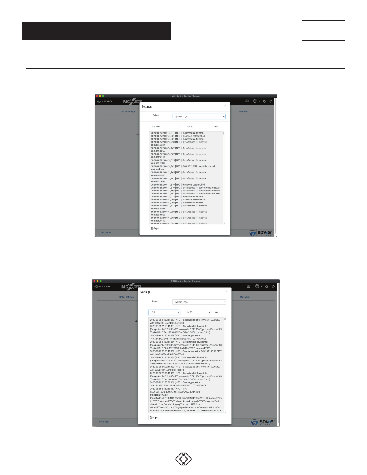
CHAPTER 8: SYSTEM SETTINGS
8.7.2 SYSTEM LOG
A System Log contains all the control layer and UI logged information.
NEED HELP?
LEAV E TH E TEC H TO US
LIVE 24/7
TECHNICAL
SUPPORT
1. 8 7 7. 8 7 7. 2 2 69
FIGURE 8-8.
8.7.3 USB LOG
A USB Log contains USB discovery and control logged information.
FIGURE 8-9.
1. 8 77. 8 7 7. 2 2 69 BLACKBOX.COM
85
Page 86
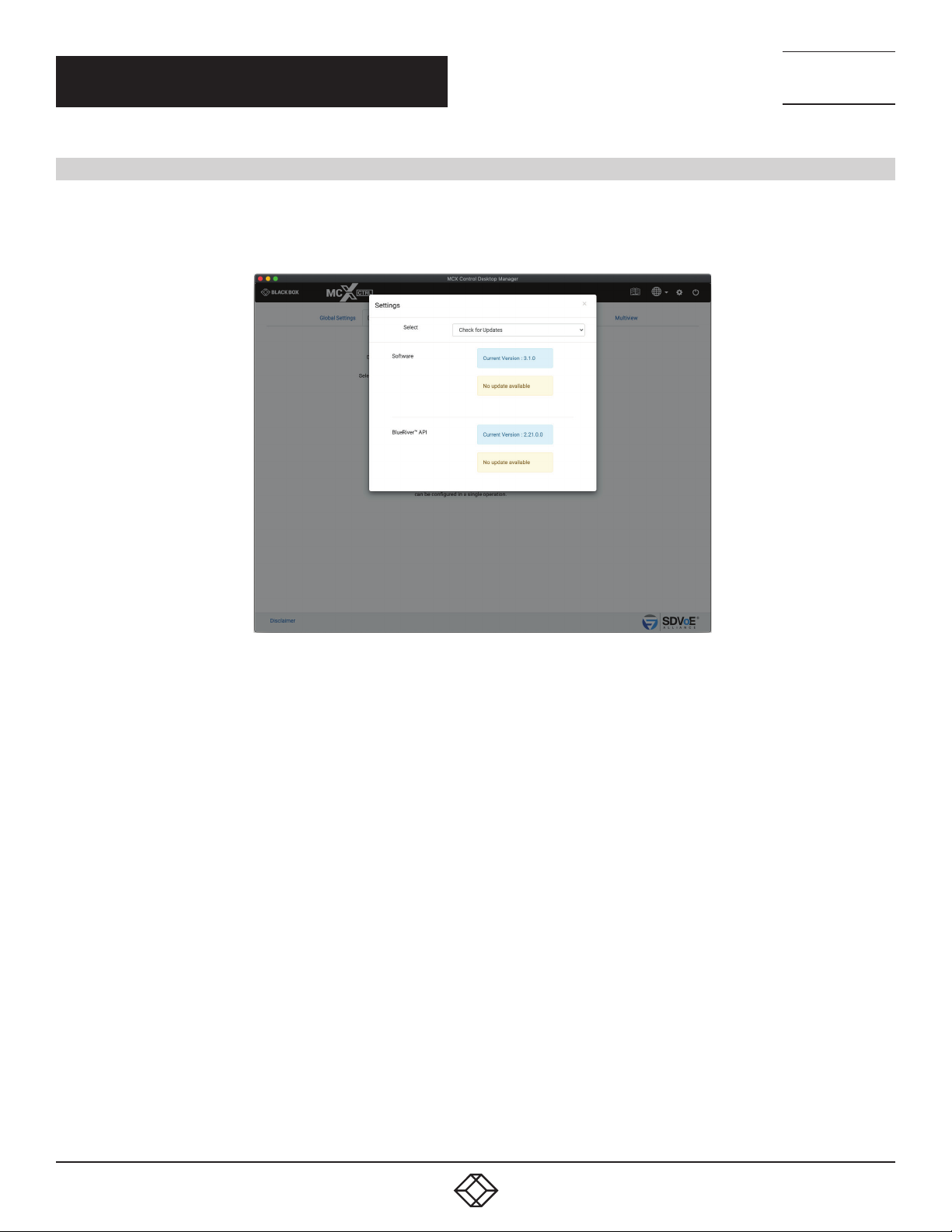
NEED HELP?
LEAV E TH E TEC H TO US
LIVE 24/7
CHAPTER 8: SYSTEM SETTINGS
8.8 CHECK FOR UPDATES
Check for Updates will contact an ftp server over the internet to obtain the latest releases. These system updates are separated into
different sections depending on the type of data to be updated.
Software is User Interface and Control Layer (API) updates MCX is MCX control layer updates
TECHNICAL
SUPPORT
1. 8 7 7. 8 7 7. 2 2 69
FIGURE 8-10.
86
1. 8 77. 8 7 7. 2 2 69 BLACKBOX.COM
Page 87
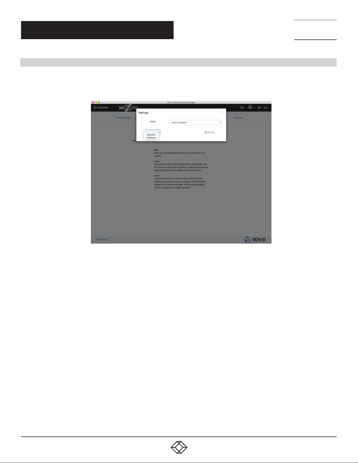
NEED HELP?
LEAV E TH E TEC H TO US
LIVE 24/7
CHAPTER 8: SYSTEM SETTINGS
TECHNICAL
SUPPORT
1. 8 7 7. 8 7 7. 2 2 69
8.9 IMPORT UPDATES
When no internet access is available or a specific update is required the files will be provided to manually update the system.
Select the type of update being performed by either selecting Software or MCX API. Then click the browse button to select the required
file from the file dialog popup.
FIGURE 8-11.
1. 8 77. 8 7 7. 2 2 69 BLACKBOX.COM
87
Page 88
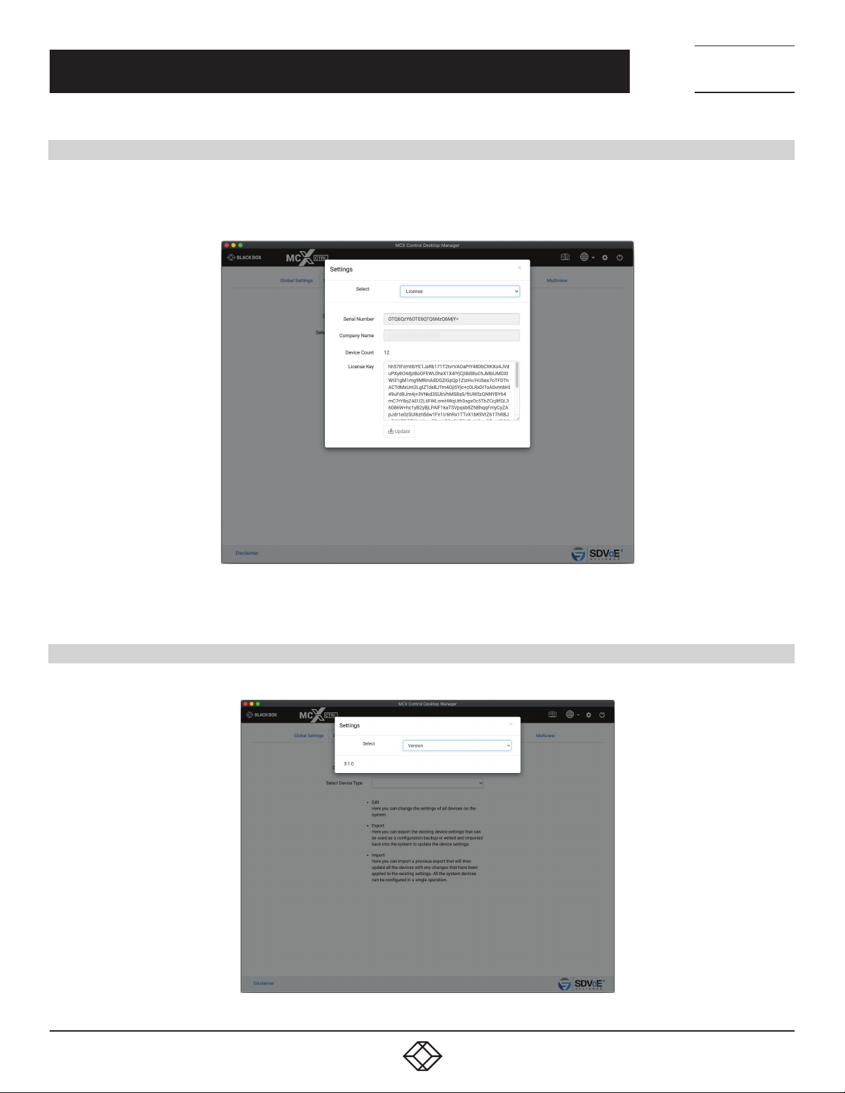
NEED HELP?
LEAV E TH E TEC H TO US
LIVE 24/7
CHAPTER 8: SYSTEM SETTINGS
8.10 L I CE N SE
The SDVoE MCX Management Controller will not operate without a valid license. When the MCX Network Management Controller is used
for the first time you will be prompted to enter a License Key. If a License Key has already been issued it can be entered into the system
from here. Contact Black Box for all licensing requirements.
TECHNICAL
SUPPORT
1. 8 7 7. 8 7 7. 2 2 69
8.11 VERSION
Here you can find the current software version.
FIGURE 8-12.
88
FIGURE 8-13.
1. 8 77. 8 7 7. 2 2 69 BLACKBOX.COM
Page 89
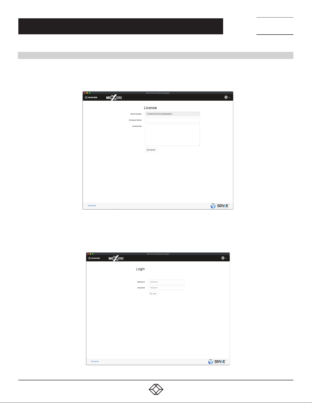
NEED HELP?
LEAV E TH E TEC H TO US
LIVE 24/7
CHAPTER 9: UI OVERVIEW
9. UI OVERVIEW
Initially when the SDVoE MCX Network Management Controller is first used you will be prompted to enter a Registration Key obtained
from your distributor. The controllers Serial Number (as shown) along with a company name will be provided to your distributor to create
the Registration Key for you. The Registration Key is also used to unlock features of MCX Network Management Controller and the
number of controllable Encoders and Decoders.
TECHNICAL
SUPPORT
1. 8 7 7. 8 7 7. 2 2 69
FIGURE 9-1.
After a successful Registration Key has been entered you will be prompted to login to the system. Initially the default login is Username:
admin Password: admin. You will be forced to change the default password as the default login will no longer be allowed. From here you
can change the language.
FIGURE 9-2.
1. 8 77. 8 7 7. 2 2 69 BLACKBOX.COM
89
Page 90
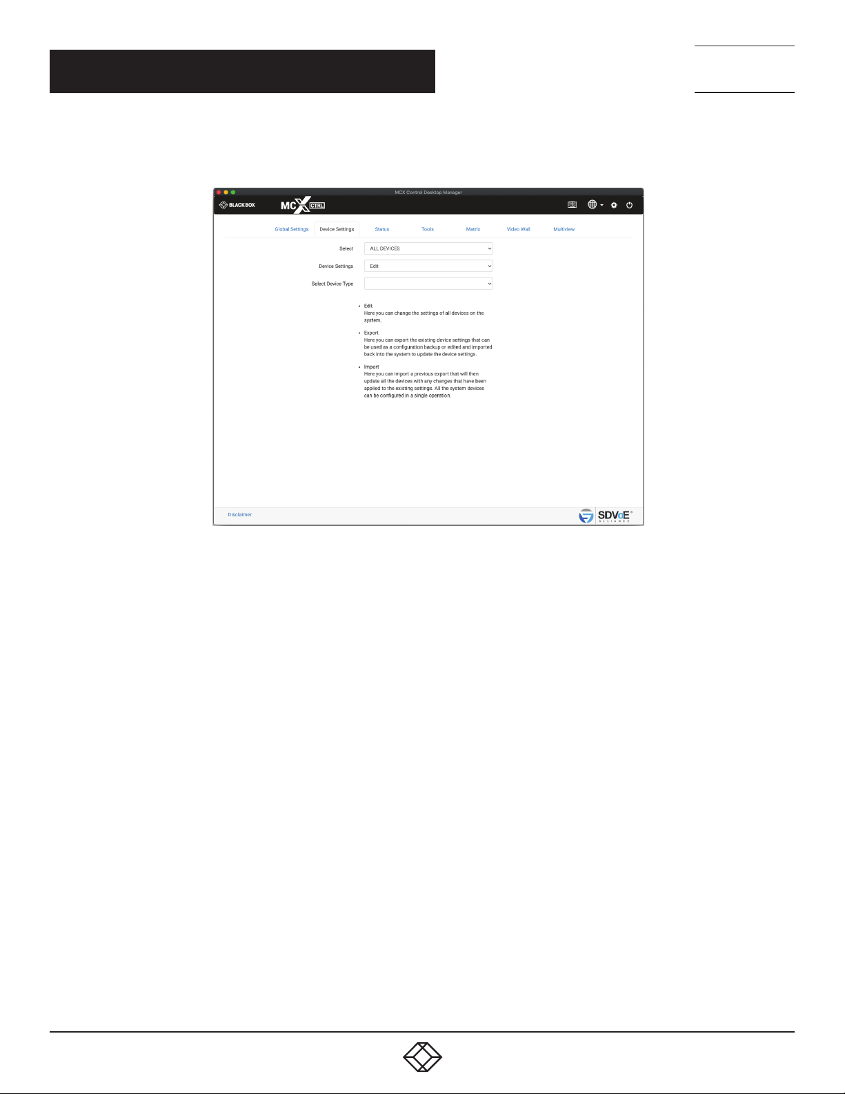
CHAPTER 9: UI OVERVIEW
Once logged into the system, the Device Settings tab will be displayed by default.
Users will automatically be logged out after 30 minues of inactivity.
NEED HELP?
LEAV E TH E TEC H TO US
LIVE 24/7
TECHNICAL
SUPPORT
1. 8 7 7. 8 7 7. 2 2 69
FIGURE 9-3.
90
1. 8 77. 8 7 7. 2 2 69 BLACKBOX.COM
Page 91
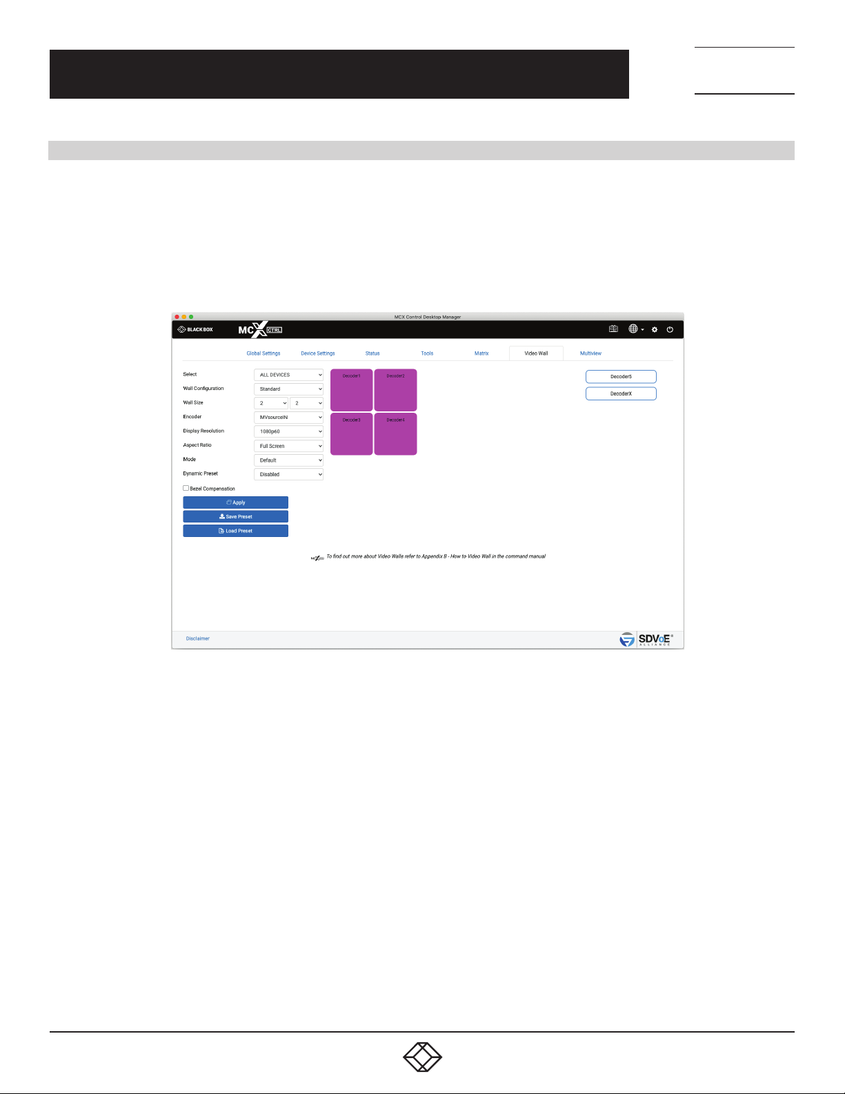
NEED HELP?
LEAV E TH E TEC H TO US
LIVE 24/7
APPENDIX A: HOW TO VIDEO WALL WITH MULTIVIEW
APPENDIX A. HOW TO VIDEO WALL WITH MULTIVIEW
Here is an explanation on how to create a Multiview layout on a video wall. To do this there are four (4) simple steps, make a physical
HDMI connection between a dedicated Decoder and Encoder, create a Video Wall preset along with Multiview presets, and lastly execute
the presets. The Video Wall preset is only required to be executed once to set up the Video Wall and to select the Multiview Encoder as
the video source. Multiple Multiview presets can then be executed to change the layout as required.
1. First, a dedicated Decoder is required to create an HDMI video signal containing the Multiview Layout. Let’s name this Decoder
MVsourceOUT. The HDMI output of this Decoder is connected to a dedicated Encoder’s HDMI input which will then convert the
Multiview layout video into a stream accessible on the network for any other Decoder to display. Let’s name this Encoder MVsourceI.
TECHNICAL
SUPPORT
1. 8 7 7. 8 7 7. 2 2 69
FIGURE A-1.
1. 8 77. 8 7 7. 2 2 69 BLACKBOX.COM
91
Page 92
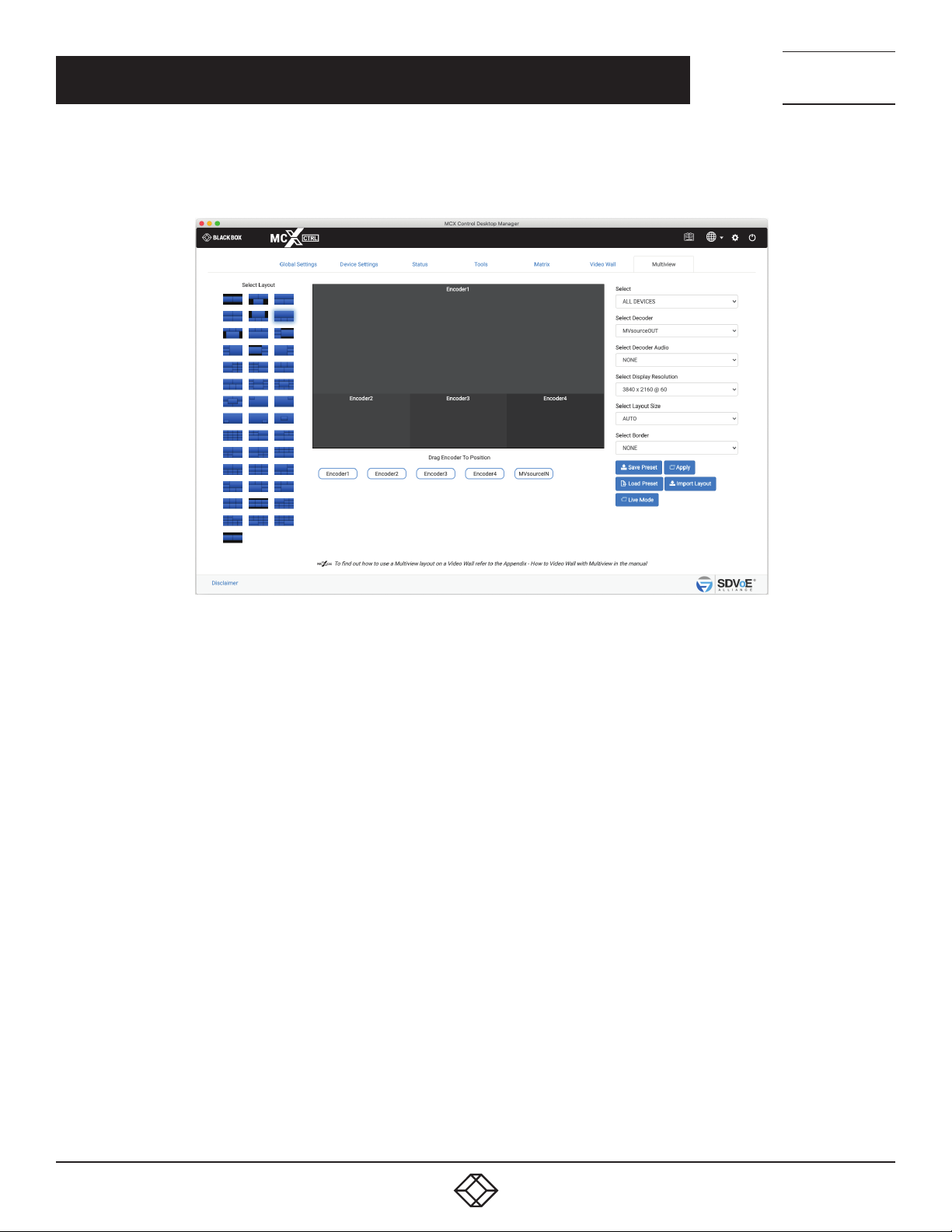
NEED HELP?
LEAV E TH E TEC H TO US
LIVE 24/7
APPENDIX A: HOW TO VIDEO WALL WITH MULTIVIEW
2. Now create a Video Wall preset using the required display layout. For this example, a 2x2 Video Wall is used and the preset is saved as
sample_VideoWall_2x2.
TECHNICAL
SUPPORT
1. 8 7 7. 8 7 7. 2 2 69
FIGURE A-2.
3. Now create a Multiview layout as required using the Decoder MVsourceOUT. For this example layout #6 is used and the preset is saved
as sample_Multiview_6.
4. Now these two presets just need to be executed. Whenever a change of the layout is required, only a different Multiview layout preset is
required to be executed as the Video Wall configuration will remain the same.
NOTE: The two presets can be combined into a single preset by editing one of them and pasting the contents of the other.
92
1. 8 77. 8 7 7. 2 2 69 BLACKBOX.COM
Page 93

NEED HELP?
LEAV E TH E TEC H TO US
LIVE 24/7
APPENDIX B: SECURITY FEATURES
TECHNICAL
SUPPORT
1. 8 7 7. 8 7 7. 2 2 69
APPENDIX B. SECURITY FEATURES
The Directory software has many security features built in which will be described in detail below. Some of these features are optional
and can be enabled or disabled depending on your system security requirements.
1. Required security key with all HTTP requests
The API of the system is accessible via HTTP PUT & GET requests which are protected with the addition of a security key that must be
passed with each request.
The security key is accessible from the Global Settings – Security Keys tab.
2. Optional security key with all TCP commands
The API of the system is accessible via TCP port 6980 which can be optionally protected with a security key that must be passed with
each command.
The security key is accessible from the Global Settings – Security Keys tab.
3. Leave Subscriptions on new Decoder detection
Without this feature there is a possibility that connecting a Decoder to the network could receive video and audio if already subscribed
(joined) to a used Encoder’s multicast address.
To eliminate this possibility any newly discovered Decoder will be issued a leave all command which will cause the Decoder to leave all
video and audio subscriptions (remove joins). This feature is active only after system start and connected Encoders and Decoders are
detected.
4. Leave Subscriptions on Stop
This is an optional feature which can be enabled or disabled from the Settings – Advanced Settings tab.
Without this feature there is a possibility of Decoders unexpectedly receiving video and audio when an Encoder starts streaming on the
same subscribed multicast address. This is optional depending on system use.
Stopping a stream can be used as a mute function for video and audio. Stop and start the stream as required and all subscribed (joined)
Decoders will respond.
But on the other hand if streams are stopped because they are no longer to be used then it could be a security issue if a bunch of
Decoders were left subscribed (joined) to this multicast address because even though a point-to-point join may be made between the
Encoder and a single Decoder, all Decoders left subscribed to the same multicast address will receive the signal.
To eliminate this possibility when the feature is enabled a leave command will be sent to all Decoders automatically on a stop command.
5. Leave Subscriptions on System Start
This is an optional feature which can be enabled or disabled from the Settings – Advanced Settings tab.
Without this feature all Decoders will still be subscribed (joined) to the same Encoders as before the system was powered off.
Some systems will be required to power on in the same state with the same joins as when powered off, while other situations this could
be a security risk.
To eliminate this possibility when the feature is enabled a leave all command will be sent to all Decoders automatically on system start.
1. 8 77. 8 7 7. 2 2 69 BLACKBOX.COM
93
Page 94

NEED HELP?
LEAV E TH E TEC H TO US
LIVE 24/7
APPENDIX B: SECURITY FEATURES
6. Permissions
Permissions has the ability to only allow certain Encoders to be joined with certain Decoders. Example: Encoder1 is only allowed to be
joined with Decoder1, and Encoder2 can be joined with any Decoder except for Decoder2. Multiple conditions can be applied.
7. Encryption
Encryption can be applied to an Encoder’s HDMI AV network data. A user defined key is set and only Decoders with the same key will be
able to decrypt the HDMI AV network data.
8. User Login Failure
This is an optional feature that is part of the system Notifications functions available from the Global Settings – Notifications tab.
An email can be sent after three (3) failed login attempts to the system.
9. Limiting simultaneous TCP connections to control port 6980
By default there is no limitation to the number of simultaneous TCP connections to control port 6980.
The number of simultaneous TCP connections can be limited between 1 and 10 from the UI Settings Advanced tab Connections Limit.
TECHNICAL
SUPPORT
1. 8 7 7. 8 7 7. 2 2 69
94
1. 8 77. 8 7 7. 2 2 69 BLACKBOX.COM
Page 95
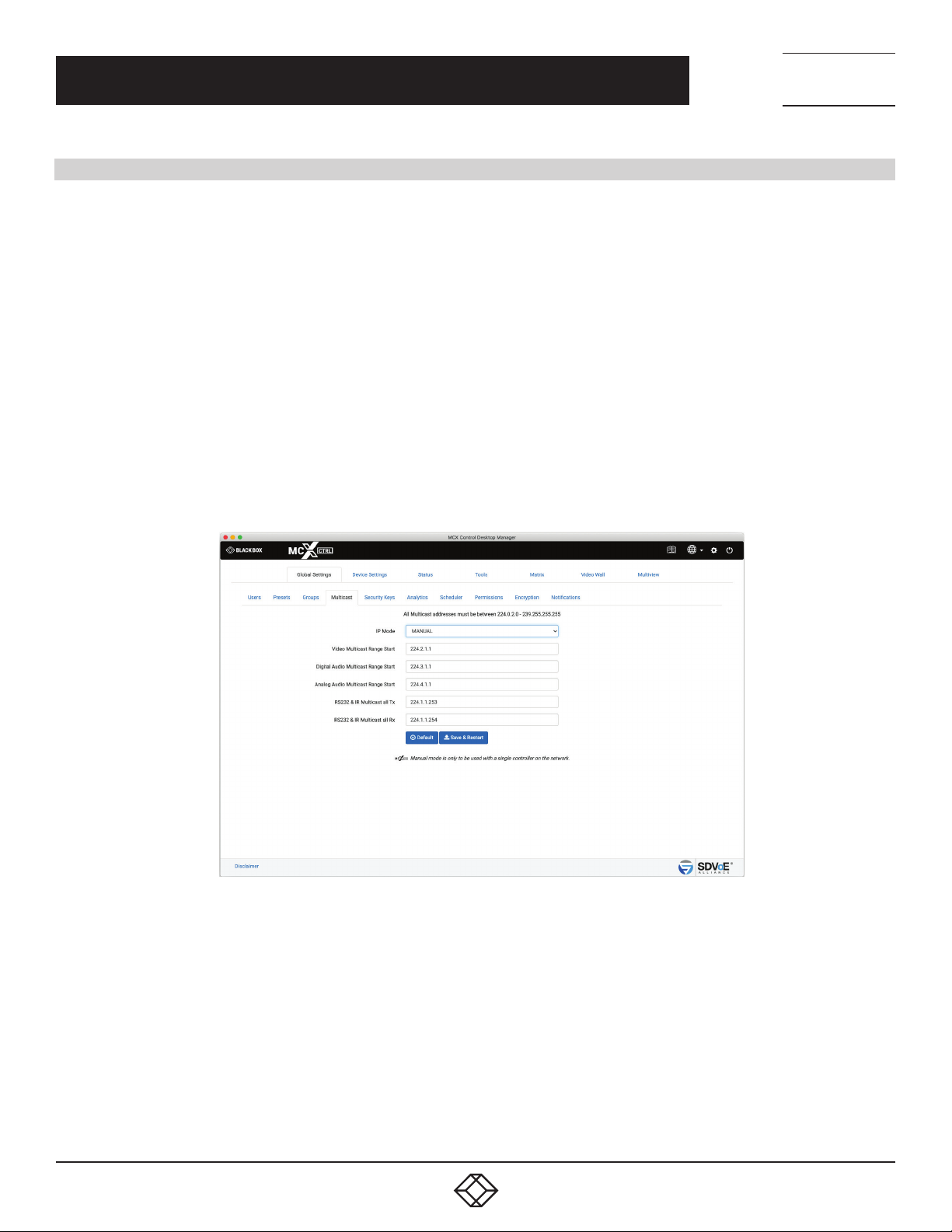
NEED HELP?
LEAV E TH E TEC H TO US
LIVE 24/7
APPENDIX C: MULTICAST MANAGEMENT
APPENDIX C. MULTICAST MANAGEMENT
Using the default MCX allocation of multicast addresses can lead to many issues which are all managed by the software when in
multicast manual mode.
All SDVoE systems work with IGMP multicast. An Encoder sends a stream on a given multicast address.
HDMI video, HDMI audio and analog audio all have separate streams with a unique multicast address assigned to each of them. Then any
given Decoder on the network subscribes to these multicast addresses to receive the streams. Due to IGMP only Decoders subscribed to
these streams will receive the network data.
If multicast addresses are not properly managed then it can lead to issues like mixed subscriptions whereby a Decoder expecting an
audio stream can in fact start receiving a video stream and vice versa.
Why? For example, let’s say a Decoder is subscribed to an audio multicast address 224.1.1.10, so we also have an Encoder streaming
audio on the same multicast address. If the Encoder is stopped and freed of its multicast address, the next stream to start is then
allocated by MCX that very same address because the next available address is used. So if a video stream is started it would be using the
same multicast address. Any Decoders still subscribed to this address expecting an audio stream will now be receiving a video stream
incorrectly.
Setting the software to Multicast Manual mode will ensure these types of mixed subscriptions can never occur by assigning a static
multicast address to each stream and keeping the allocation of multicast addresses for the different stream types in different ranges.
TECHNICAL
SUPPORT
1. 8 7 7. 8 7 7. 2 2 69
FIGURE C-1.
1. 8 77. 8 7 7. 2 2 69 BLACKBOX.COM
95
Page 96

NEED HELP?
LEAV E TH E TEC H TO US
LIVE 24/7
APPENDIX D: USING GOOGLE ASSISTANT
APPENDIX D. USING GOOGLE ASSISTANT
The MCX Network Management Controller can be controlled with voice commands via Google Assistant. In this example we will run
through the requirements to do so. An IFTTT account will also be required.
To find out how to link your Google account go to the Google help page.
The first step is to set up the MCX Network Management Controller so it is accessible from the internet. Port 80 of the MCX Network
Management Controller will need to be port-forwarded to an external IP port. For this example we are going to use an external IP address
of 123.456.789.100 and a controller IP address of 169.254.1.1. From your router, port forward from internal 169.254.1.1 port 80 to external,
say port 9999 (you can use any unused port number here).
Every router is configured differently, so consult your routers manual if required.
Now externally you should be able to access the MCX Network Management Controllers webpage by entering ‘123.456.789.100:9999’
into a browser.
Now we can set up IFTTT to activate any command on the MCX Network Management Controller but we strongly recommended that
presets only are specified.
1 Create a New Applet, then click this
2. Search for ‘google assistant’ and click it
3. Choose ‘Say a simple phrase’
4. Enter what you will say
5. Enter Google’s response
6. Click ‘Create trigger’
7. Now click that
8. Search for ‘webhooks’ and click it
9. Select ‘Make a web request’
10. Now enter the URL, for this example 123.456.789.100:9999
11. Select Method ‘POST’
12. Select Content Type ‘application/json’
13. Enter Body with command as below
14. Click ‘Create action’
{“cmd”:”<command>”,”key”:”<security_key>”}
=
{“cmd”:”preset load <preset>”,”key:”<security_key>”}
where:
<preset> = Name given to the preset to be applied
<security_key> = HTTP Security key
TECHNICAL
SUPPORT
1. 8 7 7. 8 7 7. 2 2 69
Example:
{“cmd”:”preset load ButtonPresetJoin1”,”key”:”ts2Xe1sn1Nk1rm1>l1$p1Tk18q14e”}
15. Click ‘Finish’
Now the new applet is ready for testing.
96
1. 8 77. 8 7 7. 2 2 69 BLACKBOX.COM
Page 97

NEED HELP?
LEAV E TH E TEC H TO US
LIVE 24/7
APPENDIX E: FREQUENTLY-ASKED QUESTIONS (FAQS)
TECHNICAL
SUPPORT
1. 8 7 7. 8 7 7. 2 2 69
APPENDIX E. FREQUENTLY-ASKED QUESTIONS (FAQS)
#1 Q: In Video Wall mode why do I see the video as a small image over a larger image?
A: The source resolution has reduced since the crop settings were applied.
Cropping of the source video is based on the video resolution when the source is switched to a wall layout. So when the source resolution
changes, the previous crop settings are no longer valid. Re-apply the Video Wall preset so the crop settings can be applied for the current
source resolution, or select Dynamic Preset which will automatically apply the correct crop settings on a change of source resolution for
a standard Video Wall preset.
#2 Q: Why do I see video scrolling and or tearing in Multiview mode?
A: The network bandwidth of the Encoder and / or Decoder has been exceeded.
Check the bandwidth indicated on the Status page. Try reducing the Frame Rates of the multiview and /or main streams, or turn off the
main video stream completely.
A: Incorrect layout window size.
Check the layout configuration and make sure all the windows are inline and the actual window sizes match the area available. Also check
that all windows are of an even size.
#3 Q: How does an 18Gbps 4K60 4:4:4 video signal fit down a 10Gbps network?
A: The 17.82Gbps bandwidth noted for 4K60 is the bandwidth of the total HDMI signals sent down a HDMI cable, but we don’t need to
send the same data via the network.
A 4K60 video signal has active 3840x2160 visual pixels and actually has a total of 4400x2250 pixels including timing information. We
do not need to send any of this extra information via the network as timing and other data is re-established at the Decoder before being
sent to the display. So basically we don’t need to send as much data over the network as there is in the HDMI cable itself. A 4K60 stream
becomes about 12Gbps of video data.
Video streams are limited to around 9Gbps to allow room for 1Gbps general purpose network data. All but a few resolutions will fit down
this 9Gbps pipe uncompressed and when exceeded low-latency light compression of 1.4:1 is applied for the following resolutions:
4K50-60 8-bit RGB / YCbCr 4:4:4
4K50-60 10-bit YCbCr 4:2:2
4K50-60 12-bit YCbCr 4:2:2
4K50-60 12-bit YCbCr 4:2:0
4K30 12-bit RGB / YCbCr 4:4:4
A unique compression algorithm was specifically developed with a compression ratio of just 1.4:1. When enabled, this lightweight
compression ration results is visually indistinguishable image quality. The compression codec functions in-line with the rest of the
various MCX AV processing and adds only seven (7) lines of latency (<15s for 4K60Hz). The resulting algorithm provides the industry’s
best results – video quality that is indistinguishable from native video, and with imperceptible latency.
#4 Q: Why are video walls limited to 8x5?
A: This is a simple matter of the number of pixels available from the original source to be displayed full screen on a given display. With
a source video resolution of 3840x2160 on an 8x5 video wall results in each display rendering only 480x432 of the original video. Any
less than this would result in poor picture quality with a very pixelated image. A 1920x1080 video source is worst as this only leaves
240x216 of the original video. This 480x432 / 240x216 pixel area of the original video content is then scaled up the monitor resolution of
1920x1080 or 3840x2160.
display pixel width = resolution width / number of horizontal displays display pixel height = resolution height / number of vertical displays
1. 8 77. 8 7 7. 2 2 69 BLACKBOX.COM
97
Page 98

NEED HELP?
LEAV E TH E TEC H TO US
LIVE 24/7
APPENDIX E: FREQUENTLY-ASKED QUESTIONS (FAQS)
#5 Q: What are the resolution limits of the scaler?
A: The scaler can multiply or divide by eight (8). This applies horizontally and vertically. So for example a 480x270 image can be scaled
up to 3840x2160 and a 240x135 image can be scaled up to 1920x1080. Or, a 3840x2160 image can be scaled down to 480x270 and a
1920x1080 image can be scaled down to 240x136 (must be even numbers).
#6 Q: Is there a limit to the number of Encoders or Decoders I can use on the system?
A: The simple answer is no. Limiting factors will be:
Number of licenced devices
Network capabilities
Multicast IP allocations
#7 Q: Why can I only have 2 or 3 video streams enabled before I loose video on the displays?
A: Flooding of the network switch, most likely due to IGMP (Internet Group Management Protocol) not being implemented or set-up
incorrectly on the network switch. Without correctly configured IGMP all network switch ports will receive the multicast data from all
Encoders. Once the bandwidth of a network switch port is exceed undesirable affects will occur, such as total loss or corrupted video.
IGMP insures that a given network port connected to a Decoder only receives multicast data from its subscribed Encoder.
TECHNICAL
SUPPORT
1. 8 7 7. 8 7 7. 2 2 69
#8 Q: How many simultaneous TCP connections are allowed on control port 6980?
A: Unlimited by default but this can be limited in the UI Advanced Settings section from 1 to 10 connections.
#9 Q: Is there a limit to the number of users that can access the system at any given time?
A: There are no built-in limits to the number of users that can access the system.
#10 Q: How do I find the MCX Network Management Controller on the network?
A: The default IP of the MCX Network Management Controller will be 169.254.1.1. If still unable to locate the MCX Network Management
Controller it may need to be reset back to factory default. Refer FAQ #10.
#11 Q: How do I reset the MCX Network Management Controller to factory default?
A: Insert a 3.5mm phono plug into the rear headphone socket for more than 10 seconds then unplug it.
#12 Q: What is the actual video latency of the system?
A: This depends on the mode of operation as follows:
Latency for unscaled video transport 12 lines without compression ( < 3840x2160@50 ) 17 lines with compression ( > 3840x2160@30 )
Latency for scaled video transport Sync scaling: Approximately 200 lines (this varies by input and output formats) Fast scaling: 1 to 2 frames
Latency for incorporating Multiview functionality 1 to 2 frames
#13 Q: Why do I just see noise as the image?
A: This is the result of a Decoder in fast mode with an invalid encryption key.
#14 Q: Why does an Encoder not detect a video signal higher than 4K30?
A: The Encoder EDID is most likely missing the SCDC_present bit so it is not compliant with HDMI 2.0 for resolutions greater than 4K 30Hz.
Load the default 4K60 EDID into the Encoder.
98
1. 8 77. 8 7 7. 2 2 69 BLACKBOX.COM
Page 99

NEED HELP?
LEAV E TH E TEC H TO US
LIVE 24/7
APPENDIX E: FREQUENTLY-ASKED QUESTIONS (FAQS)
TECHNICAL
SUPPORT
1. 8 7 7. 8 7 7. 2 2 69
#15 Q: What can cause a displays image to flicker?
A: Video signals at 30Hz in sync modes with the frame rate set to half will cause the image to flicker. Make sure all 30Hz signals do not have
the frame rate set to half.
#16 Q: Can there be a redundant MCX Network Management Controller on the system?
A: As long as Multicast IP Mode is kept in “AUTO” mode more than one MCX Network Management Controller can be safely connected to
the network on different IP addresses. If “MANUAL” multicast is required then both controllers must have the same multicast addresses
applied for all streams.
#17 Q: What causes the image to break up?
A: This is the result of the Encoder exceeding the network bandwidth. If using the main stream, turn off the sub stream or reduce the Frame
Rate to HALF.
#18 Q: Why is there video from an Encoder’s HDMI port but not the DisplayPort input?
A: The Encoder’s EDID is no compatible for the DisplayPort source. Set the Encoder’s EDID to either the displays EDID or use the default
4K30 or 4K60 EDID.
1. 8 77. 8 7 7. 2 2 69 BLACKBOX.COM
99
Page 100

NEED HELP?
LEAV E TH E TEC H TO US
LIVE 24/7
APPENDIX F: DISCLAIMER/TRADEMARKS
TECHNICAL
SUPPORT
1. 8 7 7. 8 7 7. 2 2 69
F.1 DISCLAIMER
Black Box Corporation shall not be liable for damages of any kind, including, but not limited to, punitive, consequential or cost of cover
damages, resulting from any errors in the product information or specifications set forth in this document and Black Box Corporation
may revise this document at any time without notice.
F.2 TRADEMARKS USED IN THIS MANUAL
Black Box and the Black Box logo type and mark are registered trademarks of Black Box Corporation.
Any other trademarks mentioned in this manual are acknowledged to be the property of the trademark owners.
100
1. 8 77. 8 7 7. 2 2 69 BLACKBOX.COM
 Loading...