

Page 1
USER MANUAL
LPS500A-MM-LC-R3, LPS500A-MM-SC-R3, LPS500A-SM-10K-LC-R3
10/100/1000B-T
TO 1000B-X POE
PSE GBE MEDIA
CONVERTER
24/7 TECHNICAL SUPPORT AT 1.877.877.2269 OR VISIT BLACKBOX.COM
LNK/ACT
SPD
PoE
LNK/ACT
PWR
10/100/1000BASE-T PoE PSE To 1000BASE-X
Media Converter
PoE-Power Sourcing Equipment
KINSUN
ALRM
15.4 W
30 W
PSE-TP
TX RX
FX
Page 2

NEED HELP?
LEAV E THE TEC H TO US
LIVE 24/7
TABLE OF CONTENTS
TECHNICAL
SUPPORT
1. 8 7 7. 8 7 7. 2 269
CONTENTS
SAFETY INFORMATION .................................................................................................................................................................................. 3
1. SPECIFICATIONS ......................................................................................................................................................................................... 4
2. OVERVIE W ..................................................................................................................................................................................................... 5
2.1 INTRODUCTION .......................................................................................................................................................................................... 5
2.2 AVAILABLE MODELS ................................................................................................................................................................................. 5
2.3 FEATURES ................................................................................................................................................................................................... 5
2.4 WHAT’S INCLUDED .................................................................................................................................................................................... 5
2.5 HARDWARE DESCRIPTION ...................................................................................................................................................................... 6
2.5.1 FRONT PANEL ......................................................................................................................................................................................................6
2.5.2 BACK PANEL ......................................................................................................................................................................................................... 6
3. INSTALLING THE CONVERTER .................................................................................................................................................................. 7
4. WDM SINGLE FIBER MODEL ...................................................................................................................................................................... 9
5. LINK FAULT PASSTHROUGH ................................................................................................................................................................... 10
6. LED DESCRIPTION ..................................................................................................................................................................................... 12
7. DIP SWITCH AND RESET BUTTON .......................................................................................................................................................... 13
8. CABLE CONNECTION PARAMETER........................................................................................................................................................ 14
A.1 ELECTRONIC EMISSION NOTICES ....................................................................................................................................................... 15
A.2 FCC CLASS A STATEMENT ...................................................................................................................................................... 15
A.3 NOM STATEMENT..................................................................................................................................................................... 16
B.1 DISCLAIMER .............................................................................................................................................................................. 17
B.2 TRADEMARKS USED IN THIS MANUAL.................................................................................................................................. 17
2
1. 87 7. 8 7 7. 2 26 9 BL ACK BOX .COM
Page 3

NEED HELP?
LEAV E THE TEC H TO US
LIVE 24/7
SAFETY INFORMATION
TECHNICAL
SUPPORT
1. 8 7 7. 8 7 7. 2 269
SAFETY INFORMATION
CAUTION: Circuit devices are sensitive to static electricity, which can damage their delicate electronics. Dry weather conditions or
walking across a carpeted floor may cause you to acquire a static electrical charge.
To protect your device, always:
Touch the metal chassis of your computer to ground the static electrical charge before you pick up the circuit device.
Pick up the device by holding it on the left and right edges only.
1. 87 7. 8 7 7. 2 26 9 BL ACK BOX .COM
3
Page 4

CHAPTER 1: SPECIFICATIONS
1. SPECIFICATIONS
TABLE 1-1. SPECIFICATIONS
SPECIFICATION DESCRIPTION
Compliance
IEEE802.3u 10/100BASE-TX, 100BASE-FX
Standards
Certifications
Data Transfer Rate
Speed 1000 Mbps, 100 Mbps, 10 Mbps
Forwarding Rate 14,880 pps, 148,800 pps, 1,488,000 pps
Flow Control
Full duplex IEEE802.3x compliant for full duplex
Half-duplex Backpressure flow control for half-duplex
Cable
UTP CAT5 cable (up to 328 ft. [100 m])
Fiber
Indicators
LEDs POWER, PoE, TP LNK/ACT, SPD, FX LNK/ACT, ALRM, 15.4 W, 30 W
Power
PSE Supports “Endpoint” via TP pin 1, 2, 3, 6
PoE Power Capacity
Power Requirement, AC Line 100 to 240 VAC, 47 to 63 Hz
Power Consumption Max. up to 65 W
Environmental
Operating Temperature 32 to 122° F (0 to 50° C)
Humidity 5% to 95%
Mechanical
Connectors
Dimensions 1.6” H x 6.2” W x 5.2” D (4.0 x 15.8 x 13.3 cm)
IEEE802.3z/ab 1000BASE-T
IEEE802.3af/at Power over Ethernet
FCC Part 15 Class A;
CE Mark
50/125, 62.5/125 or 100/140 μm multimode;
8.3/125, 8.7/125, 9/125 or 10/125 μm singlemode
802.af: 15.4 W;
802.at: 30 W
LPS500A-MM-LC-R3: (1) RJ-45 PoE, (1) pair of multimode LC;
LPS500A-MM-SC-R3: (1) RJ-45 PoE, (1) pair of multimode SC;
LPS500A-SM-10K-LC-R3: (1) RJ-45 PoE, (1) pair of singlemode LC
NEED HELP?
LEAV E THE TEC H TO US
LIVE 24/7
TECHNICAL
SUPPORT
1. 8 7 7. 8 7 7. 2 269
NOTE: For connecting this device to a router, bridge, or switch, refer to the corresponding device’s user manual.
4
1. 87 7. 8 7 7. 2 26 9 BL ACK BOX .COM
Page 5

NEED HELP?
LEAV E THE TEC H TO US
LIVE 24/7
CHAPTER 2: OVERVIEW
TECHNICAL
SUPPORT
1. 8 7 7. 8 7 7. 2 269
2. OV ERVIE W
2.1 INTRODUCTION
The unmanaged PoE PSE Media Converter is a next generation Ethernet media converter offering one gigabit per second performance.
It is used in Ethernet copper to fiber media conversion applications over long distances.
The media converter delivers one (10M/100M/1G) RJ-45 with one PoE port (supports 802.3af/at up to 15.4 W/30 W) and one GbE SC or
LC port. The converter provides high hardware performance and environment flexibility for Ethernet applications.
2.2 AVAILABLE MODELS
Three models are available:
LPS500A-MM-LC-R3: TP to Multimode Fiber Media Converter with RJ-45 and LC connectors
LPS500A-MM-SC-R3: TP to Multimode Fiber Media Converter with RJ-45 and SC connectors
LPS500A-SM-10K-LC-R3: TP to Singlemode Fiber Media Converter with RJ-45 and SC connectors
2.3 FEATURES
RJ-45 link supports IEEE 802.3ab 1000BASE-T Gbps Ethernet over twisted-pair cable
Fiber link supports IEEE 802.3z 1000BASE-X Gbps Ethernet over fiberoptic cable
Provides IEEE 802.4at maximum 30 W Power over Ethernet (PoE)
DIP switch sets PoE, LFP, and normal/cut-through configurations
Power over Ethernet (PoE): The PoE converter provides PoE power and supports various PoE PD device types (IP-phone, IP-camera,
WiFi-AP) for end users to eliminate an extra power cable to these devices
Link Fault Passthrough (LFP): When this is enabled, the UTP receiver is passed to the fiber transmitter to make the media converter
appear transparent to the end devices that are connected. It uses LFP to indicate when far-end fault issues occur. If a fault occurs, the end
devices indicate a failure for troubleshooting.
2.4 WHAT’S INCLUDE D
Your package should contains the following items. If anything is missing or damaged, contact Black Box Technical Support
at 877-877-2269 or [email protected]
10/100/1000BASE-T to 1000BASE-X PoE PSE GbE Media Converter
AC Power Cord
1. 87 7. 8 7 7. 2 26 9 BL ACK BOX .COM
5
Page 6
CHAPTER 2: OVERVIEW
2.5 HARDWARE DESCRIPTION
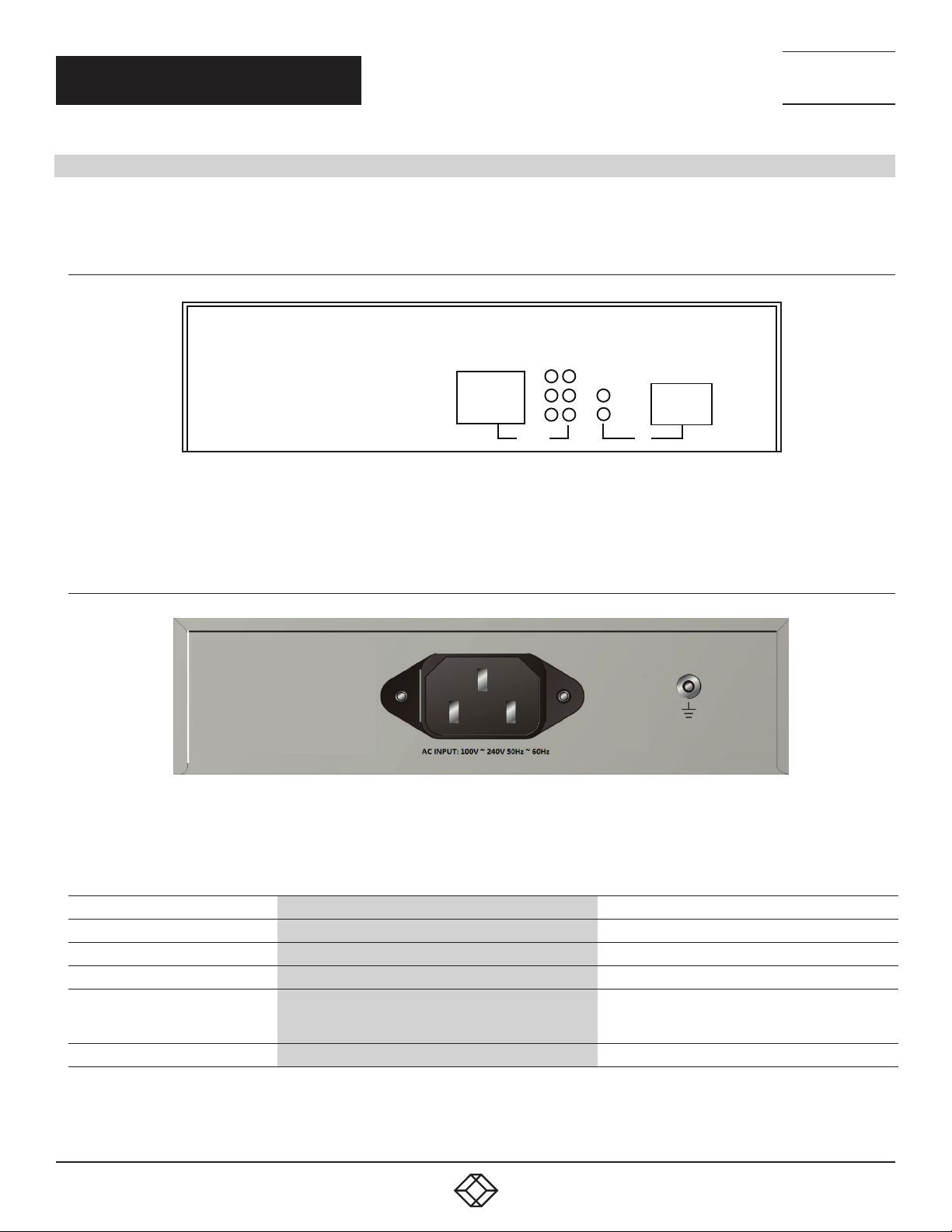
Figures 2-1 and 2-2 show the front and back panel sof the converter. Table 2-1 describes the components.
2.5.1 FRONT PANEL
PSE 10/100/1000Base-TX to 1000Base-X Media Converter
NEED HELP?
LEAV E THE TEC H TO US
LIVE 24/7
TECHNICAL
SUPPORT
1. 8 7 7. 8 7 7. 2 269
2.5.2 BACK PANEL
PoE-Power Sourcing Equipment
802.3af Endpoint
FIGURE 2-1. POE PSE MEDIA CONVERTER FRONT PANEL
FIGURE 2-2. POE PSE MEDIA CONVERTER BACK PANEL
ALRM
15.4 W
30 W
PSE-TP
LINK/ACT
SPD
POE
1310nm/1550nm
FDX/COL
PWR
FX
1 2 3 4
5
TABLE 2-1. CONVERTER COMPONENTS
NUMBER IN FIGURE 2-1 OR 2-2 SIGNAL DESCRIPTION
1 (1) RJ-45 PoE connector Links to Powered Device (PD)
2 (6) TP LEDs: PoE, TP LNK /ACT, SPD, ALRM, 15.4 W, 30 W Indicates twisted-pair port status
3 (2) FX LEDs: Power, FX LNK/ACT Indicates fiber port status
LPS500A-MM-LC-R3 : (1) multimode LC connector:
4
5 (1) 3-prong power connector Links to 100 to 240 VAC, 47 to 63 Hz power
6
LPS500A-MM-SC-R3: (1) multimode SC connector;
LPS500A-SM-10K-LC-R3: (1) singlemode LC connector
1. 87 7. 8 7 7. 2 26 9 BL ACK BOX .COM
Links to Gigabit fiber network
Page 7
CHAPTER 3: INSTALLING THE CONVERTER
3. INSTALLING THE CONVERTER
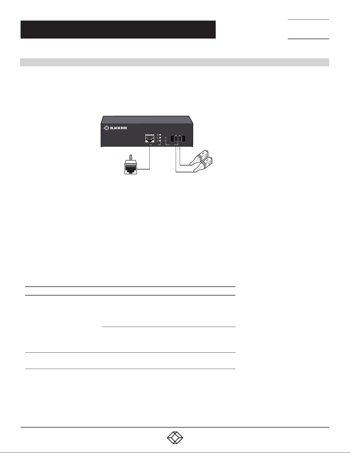
PSE TP-Fiber Converter with Powered Device (PD)
1. Connect the PSE media converter to an AC power source.
2. Install the UTP media cable to the IEEE 802.3af PD converter.
TX RX
LNK/ACT
ALRM
KINSUN
15.4 W
SPD
10/100/1000BASE-T PoE PSE To 1000BASE-X
Media Converter
PoE-Power Sourcing Equipment
To PD device
30 W
PSE-TP
CAT5
cable
LNK/ACT
PWR
PoE
Fiber
cable
FX
To Gigabit fiber network
NEED HELP?
LEAV E THE TEC H TO US
LIVE 24/7
TECHNICAL
SUPPORT
1. 8 7 7. 8 7 7. 2 269
FIGURE 3-1. MEDIA CONVERTER CONNECTIONS
NOTE: It can work as a pure converter that connects to the non-PoE converter.
3. Install the media cable for network connection.
WARNING:
Verify that the AC input conforms to your country AC power requirement and then insert the power plug.
Ensure that the power of PSE device is turned on
Install the media cable for network connection
TABLE 3-1. CONNECTOR FUNCTIONS
CONNECTOR FUNCTION
10/10 0BA SE-T X:
Auto-Negotiation
Auto-MDIX
flow control for Full-Duplex
TP Port
Fiber Port
backpressure for Half-Duplex
1000BASE-TX:
Auto-Negotiation mode
Auto-MDIX only for Auto-Negotiation
flow control for Full-Duplex only
1000BASE-SX/L X (SC/LC) with flow control
NOTE: Link partner must be 1000FDX with flow control
1. 87 7. 8 7 7. 2 26 9 BL ACK BOX .COM
7
Page 8
CHAPTER 3: INSTALLING THE CONVERTER
TX
1000BASE-X
Fiber Network
Converter/Switch
PoE PD or
PoE Splitter
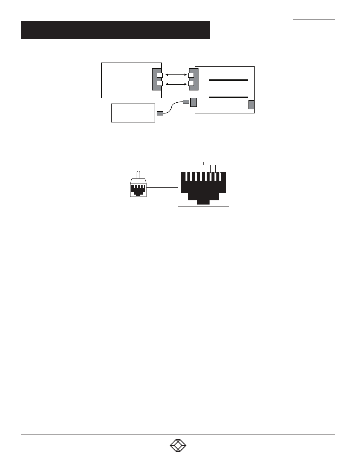
FIGURE 3-2. PSE TO PD OR POE SPLITTER
RX
TX
RX
Signal Pairs 48V
PoE PSE TP-to -GbE
Fiber Converter
+
+
_
_
NEED HELP?
LEAV E THE TEC H TO US
LIVE 24/7
TECHNICAL
SUPPORT
1. 8 7 7. 8 7 7. 2 269
CAT-5 Cable
RJ-45 Connector
765 4
8
2 1
3
FIGURE 3-3. ENDPOINT PSE RJ-45 MALE CONNECTOR
NOTE: IEEE802.3af assigns pairs on the RJ-45 connector and Cat.5 cable of Endpoint PSE.
Endpoint : -48V via TP pin 1, 2, 3, 6
8
1. 87 7. 8 7 7. 2 26 9 BL ACK BOX .COM
Page 9
NEED HELP?
LEAV E THE TEC H TO US
LIVE 24/7
CHAPTER 4: WDM SINGLE-FIBER MODEL
TECHNICAL
SUPPORT
1. 8 7 7. 8 7 7. 2 269
4. WDM SINGLE FIBER MODEL
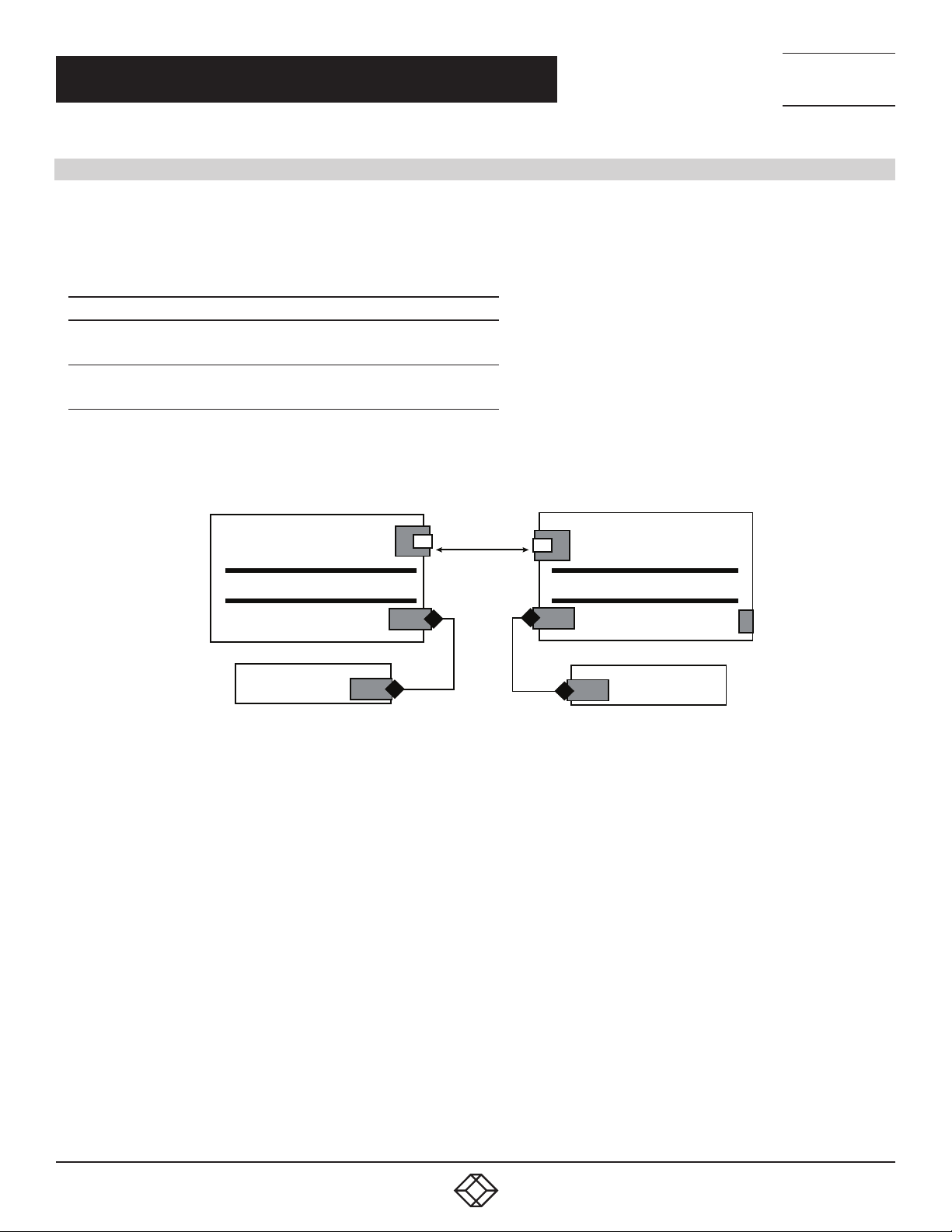
The TP-Fiber converter is specially designed with an optic Wavelength Division Multiplexing (WDM) model that can transport a
bidirectional full duplex signal over a single fiber simultaneously.
TABLE 4-1. SINGLE-FIBER TX/RX WAVELENGTH
SINGLE-FIBER MODEL TX/RX WAVELENGTH
1310-nm singlemode 10 km
1550-nm singlemode 10 km
NOTE: The 1310 nm and 1550 nm models must be installed in pairs, i.e., install 1310 nm model at one end and 1550 nm model at the
other one.
TX (Transmit) 1310 nm
RX (Receive) 1550 nm
TX (Transmit) 1550 nm
RX (Receive) 1310 nm
TX-1310/RX-1550
PoE PS E TP-to- GbE Fiber
WDM Single Fiber
PoE PD
Single Fiber
TP
TP
FIGURE 4-1. POWER FROM PSE TO PD
TX-155 0/RX-1310
PoE PS E TP-to- GbE Fiber
WDM Single Fiber
TP
TP
1. 87 7. 8 7 7. 2 26 9 BL ACK BOX .COM
9
Page 10
NEED HELP?
LEAV E THE TEC H TO US
LIVE 24/7
CHAPTER 5: LINK FAULT PASSTHROUGH
5. LINK FAU LT PASSTHRO UGH
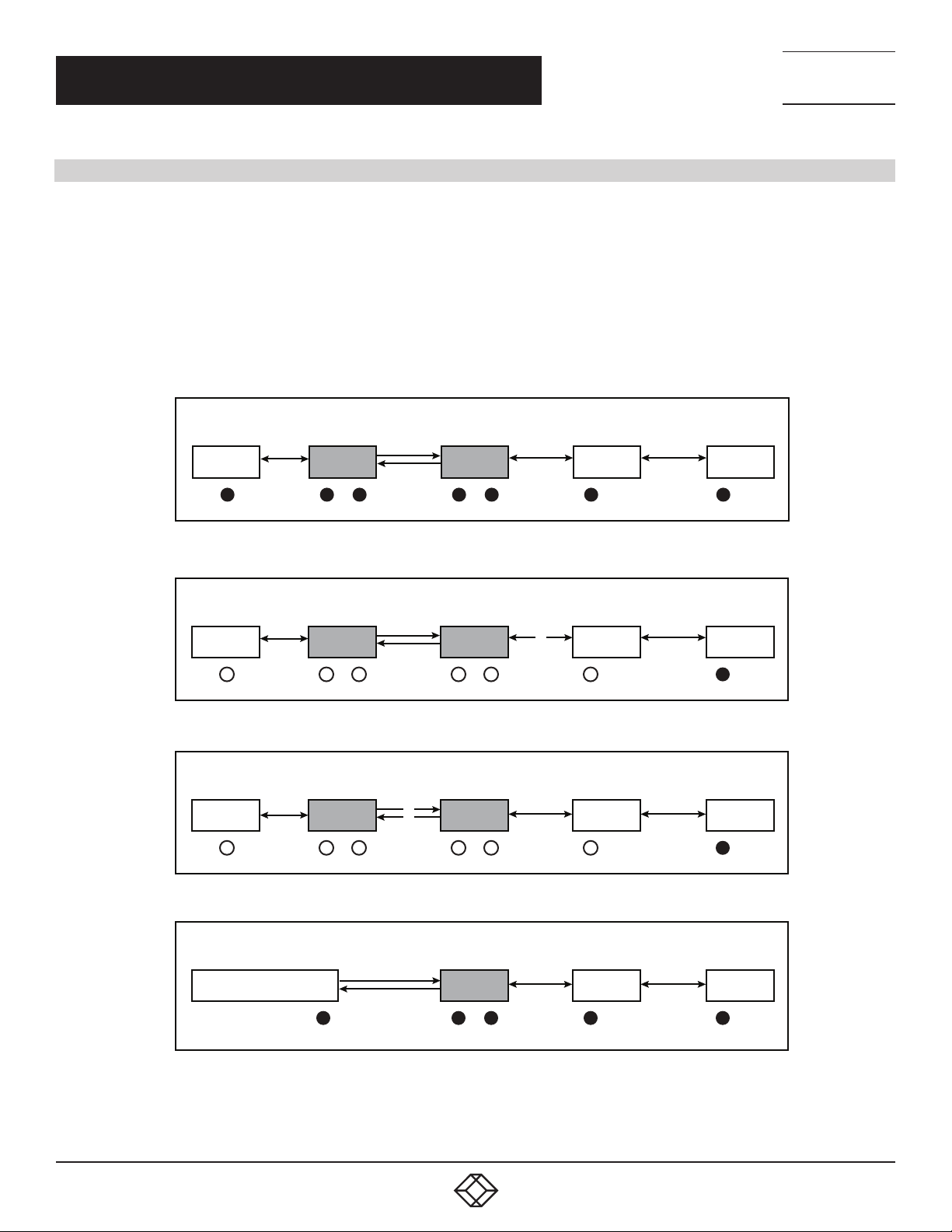
The LFP (link fault passthrough) in a TX/FX converter application is controlled by the software and instantly takes effect. Link status on
one port is propagated to the other port to notice the remote nodes. If the TP port is unplugged, this converter stops transmission on the
fiber port. This causes the remote fiber node link to fail. An LED shows the link failure on both TP and fiber ports. If the fiber link fails, this
converter restarts auto-negotiation on the TP port but always stays in the link failure state. This causes the remote TP node link to fail.
An LED also shows the link failure on both TP and fiber ports. Refer to Figure 5-1 shown below for the normal status when the link
succeeds.
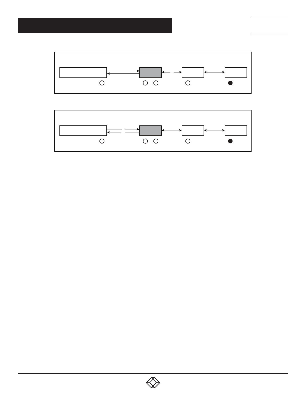
Also refer to Figure 5-2 and Figure 5-3 for the error status when TP Cable A, Fiber Cable B, or Fiber Cable C fails to connect.
NOTE: Link fault pass through (LFP) function only takes effect as S1-Bit2 (see Figure 5-4) is enabled. Disabled S1-Bit2 will turn this media
converter into a general one.
TECHNICAL
SUPPORT
1. 8 7 7. 8 7 7. 2 269
GbE
Switch
GbE
Switch
GbE
Switch
GbE
Switch
D AB
TP
LFP
C
LFP
TP
Fiber
Cable
FIGURE 5-1. NORMAL STATUS VIA LFP CONVERTER
GbE
Switch
D AB
TP
LFP
C
LFP
TP
Fiber
Cable
FIGURE 5-2. THE STATUS AS TP CABLE A OR D IS BROKEN
GbE
Switch
D AB
TP
LFP
C
LFP
TP
Fiber
Cable
Remote
Station
Remote
Station
Remote
Station
10
FIGURE 5-3. THE STATUS AS FIBER CABLE B OR C IS BROKEN
GbE Fiber
Switch
GbE
Switch
AB
LFP
C
TP
Fiber
Cable
FIGURE 5-4. NORMAL STATUS VIA LFP CONVERTER
1. 87 7. 8 7 7. 2 26 9 BL ACK BOX .COM
Remote
Station
Page 11
CHAPTER 5: LINK FAULT PASSTHROUGH
NEED HELP?
LEAV E THE TEC H TO US
LIVE 24/7
TECHNICAL
SUPPORT
1. 8 7 7. 8 7 7. 2 269
GbE Fiber
Switch
GbE
Switch
Remote
Station
AB
LFP
C
TP
Fiber
Cable
FIGURE 5-5. THE STATUS AS TP CABLE A IS BROKEN
GbE Fiber
Switch
GbE
Switch
Remote
Station
AB
LFP
C
TP
Fiber
Cable
FIGURE 5-6. THE STATUS AS FIBER CABLE B OR C IS BROKEN
NOTE:
Black circle: Indicates LNK/ACT LED Lit
Open circle (black outline): Indicates LNK/ACT LED Off
NOTE: The LFP (Link Fault Passthrough) function can work with different link partners (for example: Fiber port on Switch). It does not need
both converters with the same model in pairs.
1. 87 7. 8 7 7. 2 26 9 BL ACK BOX .COM
11
Page 12

CHAPTER 6: LED DESCRIPTION
6. LED DESCRIPTION
TABLE 6-1. LED INDICATORS
LED COLOR FUNCTION
FX LNK /ACT Green
TP LNK/ACT Green
TP SPD Green/ Yellow
PWR Green
PoE Green/Red
ALRM Red Lit red for Alarm
15. 4 W Green Lit when PD Class Type is Class 0–3
30 W Green Lit when PD Class Type is Class 4
Lit when fiber connection is good
Blinks when packet is forwarding on fiber port
Lit when TP connection is good
Blinks when packet is forwarding on TP port
Green lit when TP speed is 1000 Mbps
Yellow lit when TP speed is 100 Mbps
Off when TP speed is 10 Mbps
Lit when power is coming up
Off when power was turned off
Lit green when PoE power is active
Lit red when PoE feeling was disrupted (In case of
over-temp or over-current)
Off when PoE power was turned off
NEED HELP?
LEAV E THE TEC H TO US
LIVE 24/7
TECHNICAL
SUPPORT
1. 8 7 7. 8 7 7. 2 269
12
1. 87 7. 8 7 7. 2 26 9 BL ACK BOX .COM
Page 13
CHAPTER 7: DIP SWITCH AND RESET BUTTON
7. DIP SWITC H AND RESET BUT TON
RESET
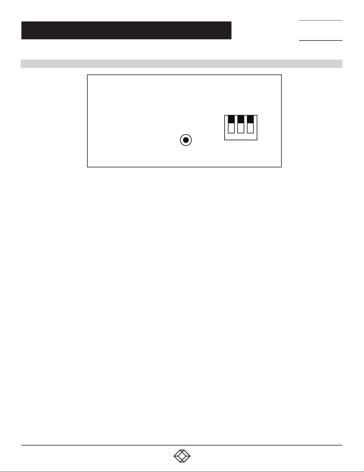
FIGURE 7-1. RESET BUTTON AND S1—BIT 1, 2, 3 CONFIGURATION AND SETTING
Cut through
LFP
LFP DIS
Normal
PoE
PoE DIS
NEED HELP?
LEAV E THE TEC H TO US
LIVE 24/7
TECHNICAL
SUPPORT
1. 8 7 7. 8 7 7. 2 269
Reset: Once S1-1, S1-2 is changed, press this button to activate the setting
S1-1 Bridge mode : Cut through (default) or Normal
S1-2 LFP : LFP enabled(default) or disabled
S1-3 PoE ON/OFF : Enable(default) or disable
NOTES:
1. S1-1 : Cut through mode support jumbo frame size max. up to 9216 bytes. Normal mode max. frame size up to 2048 .bytes
2. S1-3 : Must be set to PoE ON while power supplies to PD.
1. 87 7. 8 7 7. 2 26 9 BL ACK BOX .COM
13
Page 14

NEED HELP?
LEAV E THE TEC H TO US
LIVE 24/7
CHAPTER 8: CABLE CONNECTION PARAMETER
8. CABLE CONNECTION PARAMETER
1000BASE-SX/LX networks only support full-duplex mode. The Switch based Media Converter breaks up TP and Fiber segments’
collision domain to extend the cabling distance.
UTP Cables: CAT5, or above CAT5e class UTP cables
UTP Cable Limitations: Max. Length up to 328 feet (100 m)
Fiber Cables:
- 1000BASE-SX: 50/125, 62.5/125, or 100/140μm multimode
- 1000BASE-LX: 8.3/125, 8.7/125, 9/125 or 10/125μm singlemode
TABLE 8-1. FIBER CABLE LIMITATIONS
LED MULTIMODE FIBER SINGLEMODE FIBER
1000BASE-SX
(850 N M)
1000BASE-LX
(1310/1550 NM)
BANDWIDTH
MHZ- K M
260 220 m 400 500 m
200 275 m 500 550 m
Single-Mode Fiber 9/125μm: 2Km
Single-Mode Transceiver 1310nm: 10/30Km
Single-Mode Transceiver 1550nm: 50Km
DI STANCE
BANDWIDTH
MHZ- K M
DI STANCE
TECHNICAL
SUPPORT
1. 8 7 7. 8 7 7. 2 269
TABLE 8-2. SINGLE-FIBER TX/RX WAVELENGTH
SINGLE-FIBER MODEL TX/RX WAVELENGTH
1310-nm singlemode 10 km
1550-nm singlemode 10 km
NOTE: The 1310 nm and 1550 nm models must be installed in pairs, i.e., install 1310 nm model at one end and 1550 nm model at the
other end.
TX (Transmit) 1310 nm
RX (Receive) 1550 nm
TX (Transmit) 1550 nm
RX (Receive) 1310 nm
14
1. 87 7. 8 7 7. 2 26 9 BL ACK BOX .COM
Page 15

NEED HELP?
LEAV E THE TEC H TO US
LIVE 24/7
APPENDIX A: REGULATORY INFORMATION
A.1 ELECTRONIC EMISSION NOTICES
This equipment has been tested and found to comply with the FCC Part 15, Subpart B, Class A and protection requirements of European
Emission Standard as follows:
EMI Comply with FCC Part 15 Class A & CE Mark Approval
LVD EN 62368-1
Safety UL and others by request
A.2 FCC C LASS A STATE ME NT
This equipment generates, uses, and can radiate radio-frequency energy, and if not installed and used
properly, that is, in strict accordance with the manufacturer’s instructions, may cause interference to radio communication. It has
been tested and found to comply with the limits for a Class A computing device in accordance with the specifications in Subpart
B of Part 15 of FCC rules, which are designed to provide reasonable protection against such interference when the equipment is
operated in a commercial environment. Operation of this equipment in a residential area is likely to cause interference, in which
case the user at his own expense will be required to take whatever measures may be necessary to correct the interference.
Changes or modifications not expressly approved by the party responsible for compliance could void the user’s authority to operate
the equipment.
This digital apparatus does not exceed the Class A limits for radio noise emission from digital apparatus set out in the Radio
Interference Regulation of Industry Canada.
Le présent appareil numérique n’émet pas de bruits radioélectriques dépassant les limites applicables aux appareils numériques
de classe A prescrites dans le Règlement sur le brouillage radioélectrique publié par Industrie Canada.
TECHNICAL
SUPPORT
1. 8 7 7. 8 7 7. 2 269
1. 87 7. 8 7 7. 2 26 9 BL ACK BOX .COM
15
Page 16

NEED HELP?
LEAV E THE TEC H TO US
LIVE 24/7
APPENDIX A: REGULATORY INFORMATION
A.3 N O M STATE ME N T
1. Todas las instrucciones de seguridad y operación deberán ser leídas antes de que el aparato eléctrico sea operado.
2. Las instrucciones de seguridad y operación deberán ser guardadas para referencia futura.
3. Todas las advertencias en el aparato eléctrico y en sus instrucciones de operación deben ser respetadas.
4. Todas las instrucciones de operación y uso deben ser seguidas.
5. El aparato eléctrico no deberá ser usado cerca del agua—por ejemplo, cerca de la tina de baño, lavabo, sótano mojado o cerca de
una alberca, etc.
6. El aparato eléctrico debe ser usado únicamente con carritos o pedestales que sean recomendados por el fabricante.
7. El aparato eléctrico debe ser montado a la pared o al techo sólo como sea recomendado por el fabricante.
8. Servicio—El usuario no debe intentar dar servicio al equipo eléctrico más allá a lo descrito en las instrucciones de operación.
Todo otro servicio deberá ser referido a personal de servicio calificado.
9. El aparato eléctrico debe ser situado de tal manera que su posición no interfiera su uso. La colocación del aparato eléctrico
sobre una cama, sofá, alfombra o superficie similar puede bloquea la ventilación, no se debe colocar en libreros o gabinetes que
impidan el flujo de aire por los orificios de ventilación.
10. El equipo eléctrico deber ser situado fuera del alcance de fuentes de calor como radiadores, registros de calor, estufas u otros
aparatos (incluyendo amplificadores) que producen calor.
11. El aparato eléctrico deberá ser connectado a una fuente de poder sólo del tipo descrito en el instructivo de operación, o como
se indique en el aparato.
12. Precaución debe ser tomada de tal manera que la tierra fisica y la polarización del equipo no sea eliminada.
13. Los cables de la fuente de poder deben ser guiados de tal manera que no sean pisados ni pellizcados por objetos colocados
sobre o contra ellos, poniendo particular atención a los contactos y receptáculos donde salen del aparato.
14. El equipo eléctrico debe ser limpiado únicamente de acuerdo a las recomendaciones del fabricante.
15. En caso de existir, una antena externa deberá ser localizada lejos de las lineas de energia.
16. El cable de corriente deberá ser desconectado del cuando el equipo no sea usado por un largo periodo de tiempo.
17. Cuidado debe ser tomado de tal manera que objectos liquidos no sean derramados sobre la cubierta u orificios de ventilación.
18. Servicio por personal calificado deberá ser provisto cuando:
A: El cable de poder o el contacto ha sido dañado; u
B: Objectos han caído o líquido ha sido derramado dentro del aparato;o
C: El aparato ha sido expuesto a la lluvia; o
D: El aparato parece no operar normalmente o muestra un cambio en su desempeño; o
E: El aparato ha sido tirado o su cubierta ha sido dañada.
TECHNICAL
SUPPORT
1. 8 7 7. 8 7 7. 2 269
16
1. 87 7. 8 7 7. 2 26 9 BL ACK BOX .COM
Page 17

NEED HELP?
LEAV E THE TEC H TO US
LIVE 24/7
APPENDIX B: DISCLAIMER/TRADEMARKS
TECHNICAL
SUPPORT
1. 8 7 7. 8 7 7. 2 269
B.1 DISCLAIMER
Black Box Corporation shall not be liable for damages of any kind, including, but not limited to, punitive, consequential or cost of cover
damages, resulting from any errors in the product information or specifications set forth in this document and Black Box Corporation
may revise this document at any time without notice.
B.2 TRADEMARKS USED IN THIS MANUAL
Black Box and the Black Box logo type and mark are registered trademarks of Black Box Corporation.
Any other trademarks mentioned in this manual are acknowledged to be the property of the trademark owners.
1. 87 7. 8 7 7. 2 26 9 BL ACK BOX .COM
17
Page 18

NOTES
__________________________________________________________________________________________________
__________________________________________________________________________________________________
__________________________________________________________________________________________________
__________________________________________________________________________________________________
__________________________________________________________________________________________________
__________________________________________________________________________________________________
NEED HELP?
LEAV E THE TEC H TO US
LIVE 24/7
TECHNICAL
SUPPORT
1. 8 7 7. 8 7 7. 2 269
__________________________________________________________________________________________________
_
_________________________________________________________________________________________________
__________________________________________________________________________________________________
__________________________________________________________________________________________________\
__________________________________________________________________________________________________
__________________________________________________________________________________________________
__________________________________________________________________________________________________
__________________________________________________________________________________________________
_________________________________________________________________________________________________
18
__________________________________________________________________________________________________
__________________________________________________________________________________________________
_______
1. 87 7. 8 7 7. 2 26 9 BL ACK BOX .COM
Page 19

NOTES
__________________________________________________________________________________________________
__________________________________________________________________________________________________
__________________________________________________________________________________________________
__________________________________________________________________________________________________
__________________________________________________________________________________________________
__________________________________________________________________________________________________
NEED HELP?
LEAV E THE TEC H TO US
LIVE 24/7
TECHNICAL
SUPPORT
1. 8 7 7. 8 7 7. 2 269
__________________________________________________________________________________________________
_
_________________________________________________________________________________________________
__________________________________________________________________________________________________
__________________________________________________________________________________________________\
__________________________________________________________________________________________________
__________________________________________________________________________________________________
__________________________________________________________________________________________________
__________________________________________________________________________________________________
_________________________________________________________________________________________________
__________________________________________________________________________________________________
__________________________________________________________________________________________________
_______
1. 87 7. 8 7 7. 2 26 9 BL ACK BOX .COM
19
Page 20

NEED HELP?
LEAVE THE TECH TO US
LIVE 24/7
TECHNICAL
SUPPORT
1.87 7.877. 2 269
© COPYRIGHT 2021. BLACK BOX CORPORATION. ALL RIGHTS RESERVED.
LPS500A-MM-LC-R3_USER_RE V2.PDF
 Loading...