

Page 1
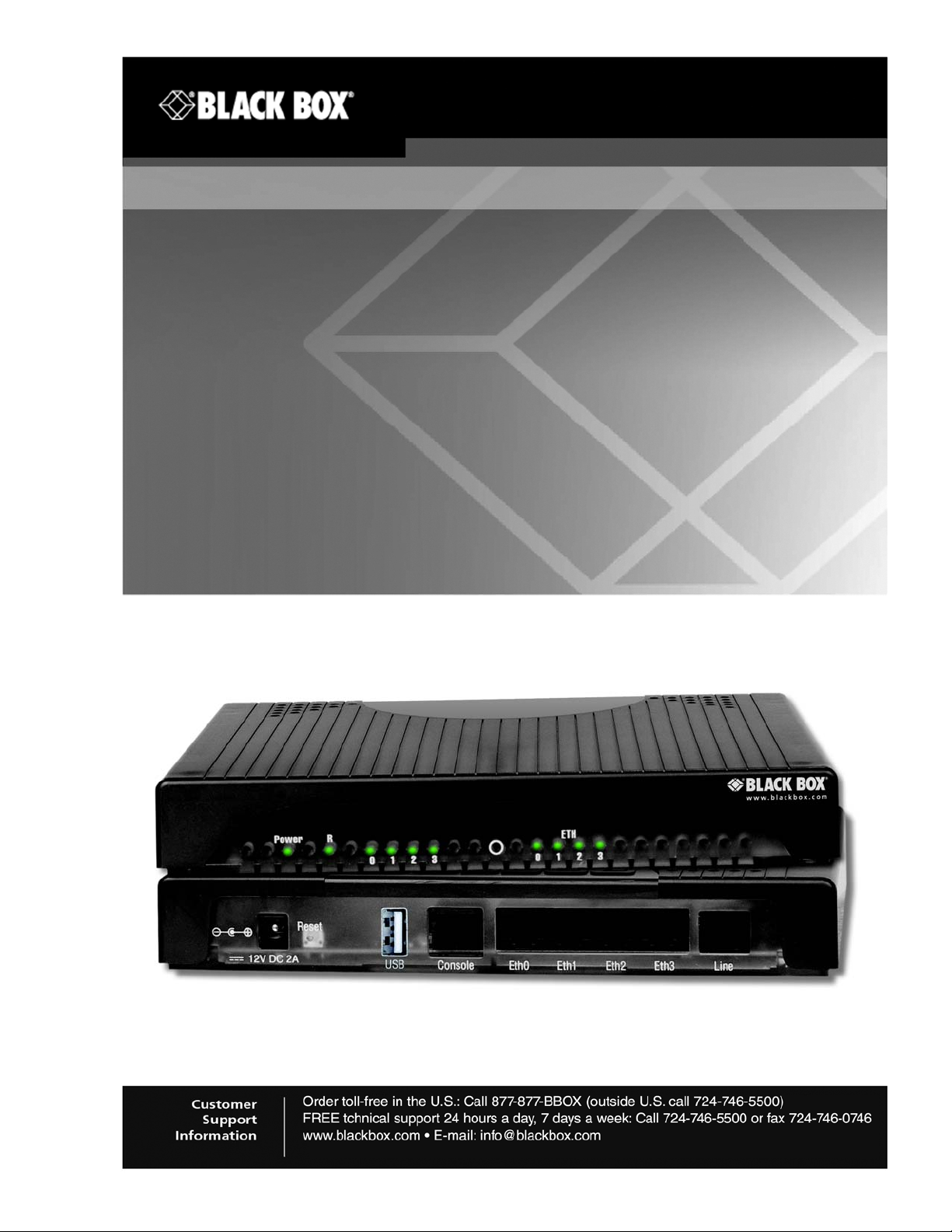
Ethernet Extender
LB522A-KIT522A-KIT-R2LB522A-KIT
LB522A-KIT-R2, LB524A-KIT-R2, LB528A-KIT-R2
Model 2960 RAS Getting Started Guide
Page 2

Black Box Ethernet Extender User Manual
Summary Table of Contents
1. About This Guide ...........................................................................................................................10
2. General Information ....................................................................................................................... 14
3. Installing the LB52XA-R2 .............................................................................................................. 18
4. Configuration and Operation ........................................................................................................ 24
5. LB52XA-R2 Bridging Contexts ..................................................................................................... 28
6. IP Context Overview ...................................................................................................................... 35
7. Command Line Interface (CLI) ......................................................................................................43
8. Accessing the CLI ..........................................................................................................................47
9. System Image Handling.................................................................................................................58
10. Configuration File Handling ..........................................................................................................61
11. Basic System Management ...........................................................................................................72
12. Wizard Interface ............................................................................................................................. 81
13. IP Routing .......................................................................................................................................87
14. SNMP Configuration ......................................................................................................................92
A. Specifications ............................................................................................................................. 105
724-746-5500 | blackbox.com
Page 2
Page 3

Black Box Ethernet Extender User Manual
Table of Contents
1. About This Guide ........................................................................................................................ 10
1.1 Audience ....................................................................................................................................... 10
1.2 Structure ........................................................................................................................................ 10
1.3 Precautions....................................................................................................................................11
1.3.1 Safety When Working With Electricity ..........................................................................................12
2. General Information .................................................................................................................... 14
2.1 Overview ....................................................................................................................................... 15
2.2 Do I Need This Guide? .................................................................................................................. 15
2.3 Technical Overview ....................................................................................................................... 15
2.4 Conceptual Overview ....................................................................................................................15
2.5 Default Configuration ..................................................................................................................... 17
3. Installing the LB52XA-R2 ............................................................................................................18
3.1 LB52XA-R2 Front Panel ............................................................................................................... 19
3.2 Planning the Installation ................................................................................................................20
3.2.1 Contents of package ..................................................................................................................... 20
3.2.2 What you will need ....................................................................................................................... 20
3.2.3 Installation .................................................................................................................................... 20
3.3 Connecting the Line Interface........................................................................................................ 21
3.4 Connecting Console Interface ....................................................................................................... 22
3.5 Connecting the Ethernet Interface ................................................................................................. 22
3.6 Connecting Power ......................................................................................................................... 23
4. Configuration and Operation......................................................................................................24
4.1 Introduction ................................................................................................................................... 25
4.2 Connect with SSH .........................................................................................................................25
4.3 Connect with Console.................................................................................................................... 25
4.4 Change the IP address (default: 192.168.200.10).........................................................................25
4.5 Change the default username ....................................................................................................... 25
4.6 Save the Configuration .................................................................................................................. 25
4.7 Line Port Commands ..................................................................................................................... 25
4.7.1 Local and Remote ........................................................................................................................ 25
4.7.2 Annex Type .................................................................................................................................. 26
4.7.3 Line Rate Configuration ................................................................................................................ 26
4.7.4 Modulation Scheme ...................................................................................................................... 26
4.7.5 Line Ports .....................................................................................................................................26
4.7.6 Signal to Noise Ratio .................................................................................................................... 26
4.7.7 Description ....................................................................................................................................26
4.7.8 Use Profile .................................................................................................................................... 26
4.7.9 Service Mode ................................................................................................................................26
4.7.10 Shutdown ...................................................................................................................................... 27
4.7.11 Exit ................................................................................................................................................27
4.7.12 Show ............................................................................................................................................. 27
5. LB52XA-R2 Bridging Contexts...................................................................................................28
5.1 Configuration Task List ................................................................................................................. 29
724-746-5500 | blackbox.com
Page 3
Page 4

Black Box Ethernet Extender User Manual
5.2 Optional Tasks............................................................................................................................... 29
5.3 Context Switch: HW Bridge ........................................................................................................... 29
5.3.1 Switch Mode Groups ................................................................................................................... 29
5.3.2 Switch Mode VLANS .................................................................................................................... 29
5.3.3 Port Configuration ......................................................................................................................... 30
5.3.4 Bindings ........................................................................................................................................ 30
5.4 Context Bridge: SW Bridge Introduction........................................................................................ 30
5.4.1 Bridge Groups ..............................................................................................................................33
5.5 Line: Overview............................................................................................................................... 33
5.5.1 Line Configuration Parameters ..................................................................................................... 34
5.5.2 Mandatory Configuration List (local sets payload rate) ................................................................34
6. IP Context Overview....................................................................................................................35
6.1 Introduction ................................................................................................................................... 36
6.2 Packet Processing in the IP Context ............................................................................................. 37
6.2.1 Classifier ....................................................................................................................................... 39
6.2.2 Network Address Port Translation (NAPT) ...................................................................................39
6.2.3 Routing-table Selection ................................................................................................................ 39
6.2.4 Access Control Lists (ACL) ...........................................................................................................39
6.2.5 Routing ......................................................................................................................................... 39
6.2.6 Packet Processing To/From Local Applications ...........................................................................39
6.3 IP Context Overview Configuration Task List ................................................................................ 40
6.4 Planning Your IP Configuration ..................................................................................................... 40
6.4.1 IP Interface Related Information ................................................................................................... 40
6.4.2 QoS Related Information .............................................................................................................. 41
6.4.3 Configuring Physical Ports ........................................................................................................... 41
6.4.4 Creating and Configuring IP Interfaces ........................................................................................ 41
6.4.5 Configuring Packet Classification ................................................................................................. 41
6.4.6 Configuring Network Address Port Translation (NAPT) ...............................................................41
6.4.7 Configuring Static IP Routing ....................................................................................................... 41
6.4.8 Configuring Access Control Lists (ACL) ....................................................................................... 42
6.4.9 Configuring Quality of Service (QoS) ........................................................................................... 42
7. Command Line Interface (CLI) ................................................................................................... 43
7.1 Introduction ................................................................................................................................... 44
7.2 Command modes .......................................................................................................................... 44
7.2.1 CLI prompt .................................................................................................................................... 44
7.2.2 Navigating the CLI ........................................................................................................................44
7.3 Command Editing .......................................................................................................................... 45
7.3.1 Command help .............................................................................................................................45
7.3.2 The No Form ................................................................................................................................45
7.3.3 Command completion ................................................................................................................... 45
7.3.4 Command history ......................................................................................................................... 45
7.3.5 Command Editing Shortcuts .........................................................................................................46
8. Accessing the CLI ....................................................................................................................... 47
8.1 Introduction ................................................................................................................................... 48
8.2 Accessing the CLI task list............................................................................................................. 48
8.3 Accessing via the console port ...................................................................................................... 49
8.3.1 Console port procedure ................................................................................................................ 49
724-746-5500 | blackbox.com
Page 4
Page 5

Black Box Ethernet Extender User Manual
8.4 Accessing via a secure configuration session over SSH...............................................................49
8.4.1 Accessing via a Telnet session ....................................................................................................50
8.4.2 Telnet Procedure .......................................................................................................................... 50
8.5 Using an alternate TCP listening port for the Telnet or SSH server .............................................. 50
8.6 Disabling the Telnet or SSH server ............................................................................................... 50
8.7 Logging on..................................................................................................................................... 50
8.8 Selecting a secure password......................................................................................................... 51
8.9 Password encryption .....................................................................................................................52
8.9.1 Factory preset superuser account ................................................................................................52
8.10 Configuring operators, administrators, and superusers................................................................. 52
8.10.1 Creating an operator account .......................................................................................................52
8.10.2 Creating an administrator account ................................................................................................ 53
8.10.3 Creating a superuser account ...................................................................................................... 53
8.11 Displaying the CLI version .............................................................................................................54
8.12 Displaying account information......................................................................................................54
8.13 Checking identity and connected users .........................................................................................54
8.14 Command index numbers ............................................................................................................. 55
8.15 Ending a Telnet, SSH or console port session ..............................................................................56
8.16 Showing command default values.................................................................................................57
9. System Image Handling ..............................................................................................................58
9.1 Introduction ................................................................................................................................... 59
9.2 System image handling task list .................................................................................................... 59
9.2.1 Displaying system image information ........................................................................................... 59
9.2.2 Copying system images from a network server to Flash memory ................................................ 60
10. Configuration File Handling .......................................................................................................61
10.1 Introduction ...................................................................................................................................62
10.2 Understanding Configuration Files ................................................................................................ 62
10.3 Shipping Configuration .................................................................................................................. 64
10.4 Configuration File Handling Task List ............................................................................................ 64
10.4.1 Copying Configurations Within the Local Memory ........................................................................64
10.4.2 Replacing the Startup Configuration with a Configuration from Flash Memory ............................66
10.4.3 Copying Configurations To and From a Remote Storage Location ..............................................66
10.4.4 Replacing the Startup Configuration with a Configuration Downloaded from TFTP Server .........67
10.4.5 Displaying Configuration File Information .....................................................................................68
10.4.6 Modifying the Running Configuration at the CLI ........................................................................... 69
10.4.7 Modifying the Running Configuration Offline ................................................................................ 69
10.4.8 Deleting a Specified Configuration ...............................................................................................71
11. Basic System Management ........................................................................................................72
11.1 Introduction ...................................................................................................................................73
11.2 Basic System Management Configuration Task List .....................................................................73
11.2.1 Managing Feature License Keys .................................................................................................. 73
11.2.2 Setting System Information .......................................................................................................... 74
11.2.3 Setting the System Banner ........................................................................................................... 75
11.2.4 Setting Time and Date .................................................................................................................. 76
11.2.5 Configuring Daylight Savings Time Rules .................................................................................... 76
11.2.6 Display Clock Information ............................................................................................................. 77
11.2.7 Display Time Since Last Restart ..................................................................................................77
724-746-5500 | blackbox.com
Page 5
Page 6

Black Box Ethernet Extender User Manual
11.2.8 Configuring the Web Server ......................................................................................................... 77
11.2.9 Restarting the System .................................................................................................................. 78
11.2.10 Displaying the System Logs .........................................................................................................78
11.2.11 Displaying Reports .......................................................................................................................79
11.2.12 Configuring the blink interval ........................................................................................................ 79
11.2.13 Configuring the Syslog Client .......................................................................................................79
12. Wizard Interface........................................................................................................................... 81
12.1 Introduction ...................................................................................................................................82
12.2 Browser Notes ............................................................................................................................... 82
12.3 Connect with Web GUI .................................................................................................................. 82
12.3.1 Management IP Setup ..................................................................................................................84
12.3.2 Line Setup .................................................................................................................................... 84
13. IP Routing..................................................................................................................................... 87
13.1 Introduction ...................................................................................................................................88
13.2 Basic Routing ................................................................................................................................88
13.3 Static Routes ................................................................................................................................. 88
13.4 Configuring static routes ................................................................................................................88
13.5 System Routes .............................................................................................................................. 89
13.6 Dynamic Routes ............................................................................................................................ 90
13.7 Show Routes ................................................................................................................................. 90
13.8 Basic Static Routing Example ....................................................................................................... 90
14. SNMP Configuration....................................................................................................................92
14.1 Introduction ...................................................................................................................................93
14.2 Simple Network Management Protocol (SNMP) ........................................................................... 93
14.2.1 SNMP Basic Components ............................................................................................................ 93
14.2.2 SNMP Basic Commands .............................................................................................................. 93
14.2.3 SNMP Management Information Base (MIB) ............................................................................... 94
14.2.4 Network Management Framework ............................................................................................... 94
14.3 Identification of an LB52XA-R2 via SNMP .................................................................................... 94
14.4 SNMP Tools ..................................................................................................................................95
14.5 SNMP Configuration Task List ...................................................................................................... 95
14.6 Setting Basic System Information..................................................................................................95
14.7 Setting Access Community Information.........................................................................................97
14.8 Setting Allowed Host Information .................................................................................................. 98
14.9 Specifying the Default SNMP Trap Target ....................................................................................98
14.10 Displaying SNMP Related Information .......................................................................................... 99
14.11 Using the ManageEngine SNMP Utilities ......................................................................................99
14.11.1 Using the MibBrowser ................................................................................................................ 100
14.11.2 Using the TrapViewer .................................................................................................................101
14.12 Standard SNMP Version 1 Traps ................................................................................................ 103
14.13 SNMP Interface Traps ................................................................................................................. 104
A. Specifications ........................................................................................................................... 105
A.1 LAN Connection .........................................................................................................................106
A.1.1 Line Connection ..........................................................................................................................106
A.2 Line Rate and Distance .............................................................................................................. 106
A.2.1 Line Rate .................................................................................................................................... 106
724-746-5500 | blackbox.com
Page 6
Page 7

Black Box Ethernet Extender User Manual
A.2.2 Distance ...................................................................................................................................... 106
A.3 LED Status Indicators ................................................................................................................. 107
A.4 Console ...................................................................................................................................... 107
A.5 Power Supply .............................................................................................................................107
A.5.1 External AC ................................................................................................................................ 107
A.5.2 External DC ................................................................................................................................ 107
A.6 Physical ...................................................................................................................................... 107
724-746-5500 | blackbox.com
Page 7
Page 8

Black Box Ethernet Extender User Manual
List of Figures
1 Twisted Pair Connection .................................................................................................................16
2 Remote/CPE Configuration .............................................................................................................17
3 LB52XA-R2 front panel ...................................................................................................................19
4 LB52XA-R2 rear panel options ....................................................................................................... 20
5 LB52XA-R2 (RJ-45) twisted pair line interface ................................................................................ 21
6 Pin-out for two devices ....................................................................................................................21
7 RJ-45 to RJ-11 cable ...................................................................................................................... 22
8 DB-9-to-RJ-45 cable diagram ......................................................................................................... 22
9 Switch mode VLANS .......................................................................................................................30
10 Bridge Network ................................................................................................................................31
11 Breaking down OS concepts ........................................................................................................... 32
12 IP context and related elements ......................................................................................................36
13 Processing order of IP services attached to an IP interface ........................................................... 38
14 Setup for initial configuration via the console port ........................................................................... 49
15 Sample configuration file .................................................................................................................63
16 Local memory regions .....................................................................................................................65
17 Remote memory regions for the OS ............................................................................................... 67
18 Login ............................................................................................................................................... 82
19 Wizard Homepage. ........................................................................................................................ 83
20 Choose Wizard ................................................................................................................................83
21 Basic Setup ..................................................................................................................................... 84
22 Configure Preview Option ............................................................................................................... 85
23 Confirmation .................................................................................................................................... 86
24 Static route example ....................................................................................................................... 91
25 ManageEngine MibBrowser displaying some of the System Group objects ...................................96
26 ManageEngine MibBrowser Settings Button on the Toolbar ........................................................ 100
27 ManageEngine TrapViewer displaying received traps ..................................................................101
28 ManageEngine Trap Details window of TrapViewer ..................................................................... 102
724-746-5500 | blackbox.com
Page 8
Page 9

Black Box Ethernet Extender User Manual
List of Tables
1 LB52XA-R2 LED descriptions ......................................................................................................... 19
2 Details available in the Trap Details window .................................................................................102
724-746-5500 | blackbox.com
Page 9
Page 10

About This Guide
1 About This Guide
This guide describes the Black Box LB52XA-R2 hardware, installation and basic configuration.
1. 1 AU D I EN C E
This guide is intended for the following users:
•
Operators
•
Installers
•
Maintenance technicians
1.2 STRUCTURE
This guide contains the following chapters and appendices:
•
Chapter 2 on page 11 provides a general introduction to the LB52XA-R2
•
Chapter 3 on page 18 provides information about installing the LB52XA-R2
•
Chapter 4 on page 24 provides information on configuring the LB52XA-R2
•
Chapter 5 on page 28 provides information on LB52XA-R2 bridging
•
Chapter 6 on page 35 provides information on the IP context overview
•
Chapter 7 on page 43 provides information about the Command Line Interface (CLI)
•
Chapter 8 on page 47 provides information on accessing the CLI
•
Chapter 9 on page 58 provides information on system image handling for the LB52XA-R2
•
Chapter 10 on page 61 provides information about configuration file handling for the LB52XA-R2
•
Chapter 11 on page 72 provides information about basic system management
•
Chapter 12 on page 81 provides information about the Wizard
•
Chapter 13 on page 87 provides information about IP routing
•
Chapter 14 on page 92 provides information about SNMP configuration
•
Appendix A on page 105 provides specifications for the LB52XA-R2
For best results, read the contents of this guide before you install the LB52XA-R2.
724-746-5500 | blackbox.com
Page 10
Page 11
About This Guide
T
1.3 PRECAUTIONS
Notes and cautions, which have the following meanings, are used throughout this guide to help you
become aware of potential Router modem problems. Warnings relate to personal injury issues, and Cau
tions refer to potential property damage.
Note A note presents additional information or interesting sidelights.
The alert symbol and IMPORTANT heading calls attention to important
information.
IMPORTAN
The alert symbol and CAUTION heading indicate a potential hazard.
Strictly follow the instructions to avoid property damage.
CAUTION
The shock hazard symbol and CAUTION heading indicate a potential
electric shock hazard. Strictly follow the instructions to avoid property
damage caused by electric shock.
CAUTION
-
WARNING
WARNING
The alert symbol and WARNING heading indicate a potential
safety hazard. Strictly follow the warning instructions to avoid
personal injury.
The shock hazard symbol and WARNING heading indicate a
potential electric shock hazard. Strictly follow the warning
instructions to avoid injury caused by electric shock.
724-746-5500 | blackbox.com
Page 11
Page 12
1.3.1 SAFETY WHEN WORKING WITH ELECTRICITY
WARNING
WARNING
• Do not open the device when the power cord is connected. For
systems without a power switch and without an external power
adapter, line voltages are present within the device when the
WARNING
power cord is connected.
• For devices with an external power adapter, the power adapter
shall be a listed Limited Power Source. The mains outlet that is
utilized to power the device shall be within 10 feet (3 meters) of
the device, shall be easily accessible, and protected by a circuit
breaker in compliance with local regulatory requirements.
• For AC powered devices, ensure that the power cable used
meets all applicable standards for the country in which it is to
be installed.
• For AC powered devices which have 3 conductor power plugs
(L1, L2 & GND or Hot, Neutral & Safety/Protective Ground), the
wall outlet (or socket) must have an earth ground.
• For DC powered devices, ensure that the interconnecting
cables are rated for proper voltage, current, anticipated tem
perature, flammability, and mechanical serviceability.
• WAN, LAN & PSTN ports (connections) may have hazardous
voltages present regardless of whether the device is powered
ON or OFF. PSTN relates to interfaces such as telephone lines,
FXS, FXO, DSL, xDSL, T1, E1, ISDN, Voice, etc. These are known
as “hazardous network voltages” and to avoid electric shock
use caution when working near these ports. When disconnect
ing cables for these ports, detach the far end connection first.
• Do not work on the device or connect or disconnect cables
during periods of lightning activity
About This Guide
-
-
This device contains no user serviceable parts. This device can
only be repaired by qualified service personnel.
In accordance with the requirements of council directive 2002/96/EC
on Waste of Electrical and Electronic Equipment (WEEE), ensure that
at end-of-life you separate this product from other waste and scrap and
deliver to the WEEE collection system in your country for recycling.
This device is NOT intended nor approved for connection to the
PSTN. It is intended only for connection to customer premise
equipment.
724-746-5500 | blackbox.com
Page 12
Page 13

About This Guide
CAUTION
Electrostatic Discharge (ESD) can damage equipment and impair
electrical circuitry. It occurs when electronic printed circuit cards are
improperly handled and can result in complete or intermittent failures.
Do the following to prevent ESD:
• Always follow ESD prevention procedures when removing and
replacing cards.
• Wear an ESD-preventive wrist strap, ensuring that it makes good
skin contact. Connect the clip to an unpainted surface of the chas
sis frame to safely channel unwanted ESD voltages to ground.
• To properly guard against ESD damage and shocks, the wrist strap
and cord must operate effectively. If no wrist strap is available,
ground yourself by touching the metal part of the chassis.
-
724-746-5500 | blackbox.com
Page 13
Page 14

2 GENERAL INFORMATION
Chapter contents
2. General Information ....................................................................................................................14
2.1 Overview.................................................................................................................................... 15
2.2 Do I Need This Guide? ...............................................................................................................15
2.3 Technical Overview..................................................................................................................... 15
2.4 Conceptual Overview .................................................................................................................. 15
2.5 Default Configuration .................................................................................................................. 17
724-746-5500 | blackbox.com
Page 14
Page 15

2 General Information
2.1 OVERVIEW
The Black Box LB52XA-R2 is a cost effective Ethernet Extender capable of achieving bandwidth rates of
over 60 Mbps. The LB52XA-R2 is the ideal choice for providing internet access to bandwidth hungry small
to medium size offices, wireless backhaul, Metro Ethernet, even LAN to LAN extensions.
The LB52XA-R2 is cable of bonding from 1 to 4 pairs to increase overall bandwidth. Each pair is capable of
up to 5.7 Mbps to 15.3 Mbps pending your distance requirements. The ability to configure pair bonding and
various line rate modes enables service providers, integrators and businesses to choose the best available
rate vs. reach combination for the application.
The LB52XA-R2 supports defaults to plug-n-play mode which will allow the Extenders to pair up automatically at the best rate achievable. Should a pair be faulty the LB52XA-R2 will automatically adjust the line
rate to ensure the network connection remains stable.
plug and play features, the managed series adds a higher level of network control for the more demanding
applications.
The network management port is securely protected. Stateful Firewall inspection of traffic, accomplished
through the creation of Access Control Lists (ACLs), enables the filtering of traffic based on numerous crite
ria including source and destination IP address, port, connection state and protocol.
Logical and physical ports are selectable for bridging. Features such VLANs are configurable on a per port
basis. Bridged traffic can be tagged and prioritized according to user defined parameters.
The LB52XA-R2 offers easy installation. The variety of configuration options include CLI via Console
(RS232), Telnet, or SSH. Also included is HTTP web based management, and SNMP.
In addition to offering all Black Box’s highly regarded
-
Black Box's managed series offer the versatility and reliability demanded for the most critical network applications at an affordable price.
2.2 DO I NEED THIS GUIDE?
If you are a network administrator or a network admin associate and you have some level of complexity in
your network applications, you may need this guide to get all of the value out of this feature-rich embedded
operating system (OS) device can deliver. The purpose of the OS CLI guide is to give you in depth refer
ence resource for every command supported in the OS.
-
2.3 TECHNICAL OVERVIEW
Ethernet extenders – “DIP SWITCH SIMPLE” You should be able to plug a Black Box Ethernet Extender 2
pack together and pass traffic immediately but if you need more features or have application requirements
that don’t function at a “plug-n-play” level then you might need this guide. If you are looking to understand
the Traffic Flow and how to troubleshoot certain parts of your network, then this guide is for you. If you are
not familiar and want to know more about the Black Box OS CLI (Command Line Interface) then this guide
is for you. If you are just curious and want to experiment with the power of the OS, this guide is for you.
2.4 CONCEPTUAL OVERVIEW
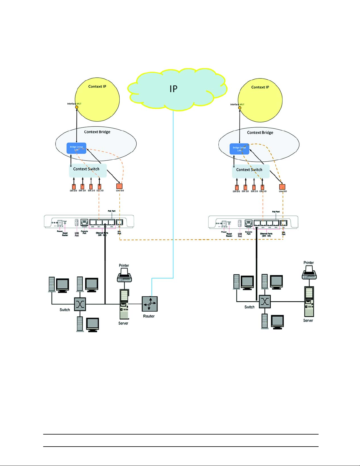
This guide will break down in to a break down the configuration concepts in the picture above so the technician will know how to manipulate the dataflow at every level of the OSI. It will also give you a detailed look
at the management and system level of the units. Although the units are capable of being simple plug and
play Ethernet extenders. Black Box has provided a way for more advanced capabilities and extreme flexibil
ity in configuring the units for your desired application requirements. Figure 1 is a conceptual break-down of
Ethernet bridging over a twisted pair connection.
-
724-746-5500 | blackbox.com
Page 15
Page 16
2 General Information
724-746-5500 | blackbox.com
Figure 1 Twisted Pair Connection
Page 16
Page 17
2 General Information
2.5 DEFAULT CONFIGURATION
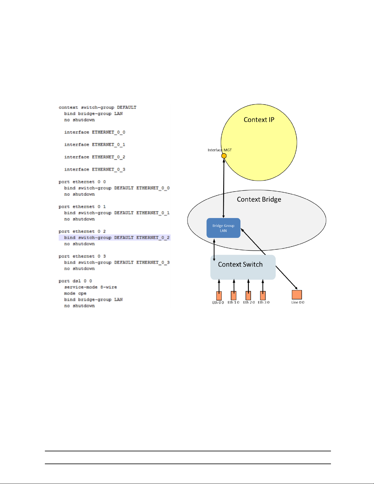
Let’s look at the data flow in combination with the conceptual view of the LB52XA-R2. This configuration is
a remote/CPE configuration as shown in
figure 2
Figure 2 Remote/CPE Configuration
First let’s have a look at traffic flow. Ethernet ports are bound to Context Switch and Context Switch is
bound directly to the Bridge Group LAN. Line is bound directly to the Bridge Group LAN. This is how the
traffic moves from the Line ports to the Ethernet Switch.
724-746-5500 | blackbox.com
Page 17
Page 18

3 INSTALLING THE LB52XA-R2
Chapter contents
3. Installing the LB52XA-R2............................................................................................................18
3.1 LB52XA-R2 Front Panel ............................................................................................................ 19
3.2 Planning the Installation .............................................................................................................. 20
3.2.1 Contents of package .................................................................................................................. 20
3.2.2 What you will need ..................................................................................................................... 20
3.2.3 Installation .................................................................................................................................. 20
3.3 Connecting the Line Interface .....................................................................................................21
3.4 Connecting Console Interface..................................................................................................... 22
3.5 Connecting the Ethernet Interface ..............................................................................................22
3.6 Connecting Power....................................................................................................................... 23
724-746-5500 | blackbox.com
Page 18
Page 19
3 Installing the LB52XA-R2
3.1 LB52XA-R2 FRONT PANEL
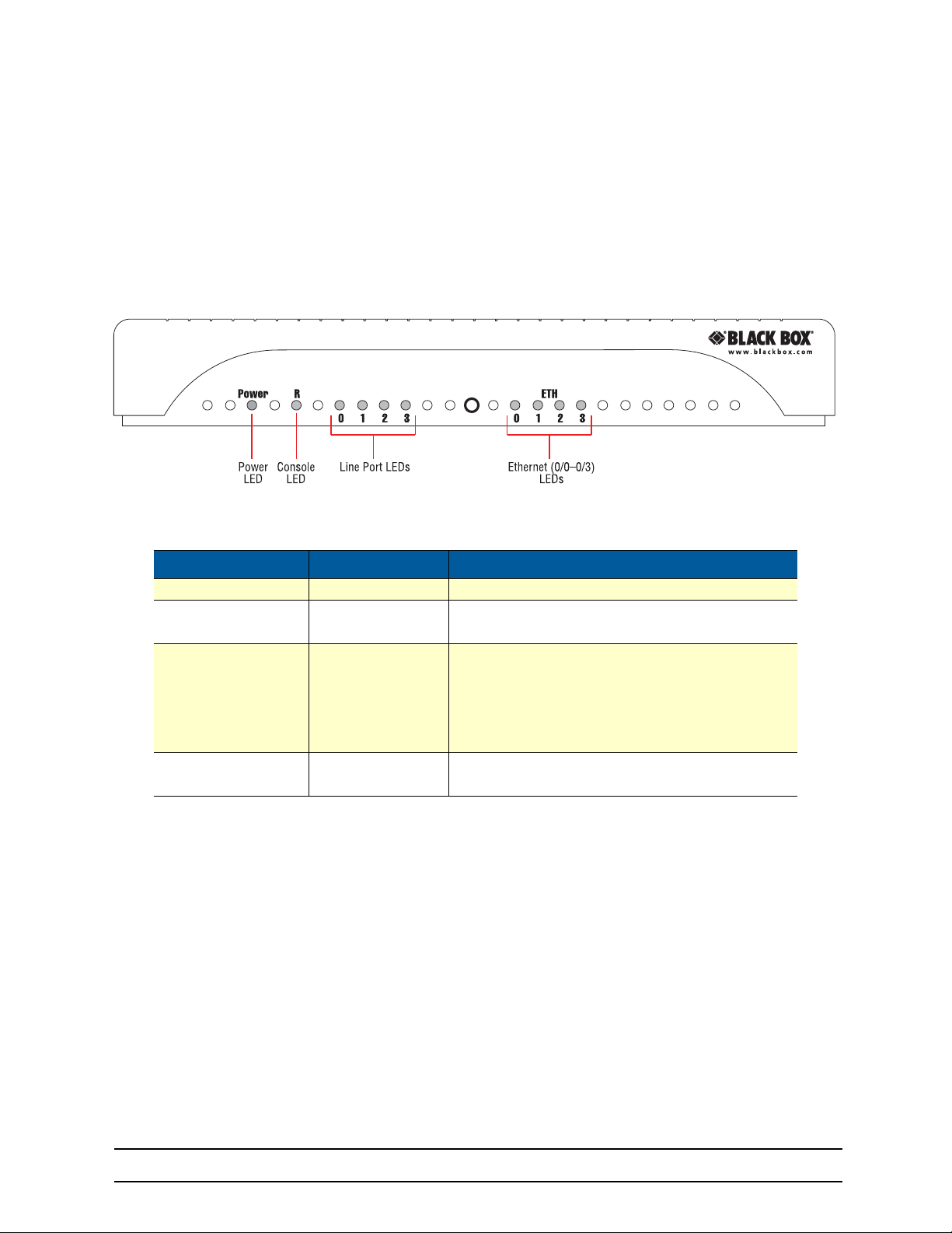
The LB52XA-R2 features front panel LEDs that monitor power, the Ethernet signals, the line connection,
and remote/local setting.
functions.
Before applying power to the LB52XA-R2, please review 3.6, “Connecting Power” on page 23 to verify that
the unit is connected to the appropriate power source.
LED Indication Description
Power ON The device is powered on.
CPE
Line Pair
(one LEAD for each
port [1 on LB522A-R2,
2 on LB524A-R2, 4 on
LB528A-R2])
Ethernet
(0/0-0/3)
Figure 3 shows the front panel location of each LED. Ta bl e 1 describes the LED
Figure 3 LB52XA-R2 front panel
Table 1. LB52XA-R2 LED descriptions
OFF
ON
OFF
ON
SLOW BLINK
FAST BLINK
ON
OFF
WAN is configured as CO.
WAN is configured as CPE.
Port is configured as DOWN.
Port is in data mode.
Port is in handshake mode (looking for a remote signal).
Port is in training mode (active communication with
remote).
Port is linked.
Data is passing over the port.
724-746-5500 | blackbox.com
Page 19
Page 20
3 Installing the LB52XA-R2
3.2 PLANNING THE INSTALLATION
3.2.1 CONTENTS OF PACKAGE
•
LB52XA-R2 Long Range Ethernet Extender
•
External power supply for LB52XA-R2
•
Ethernet cable with RJ45 plugs on each end (included)
3.2.2 WHAT YOU WILL NEED
•
Default IP address: 192.168.200.10
•
Default username: admin
•
Default password: (no password)
•
PC Computer
3.2.3 INSTALLATION
To install the LB52XA-R2 Ethernet Extender, do the following:
1. Connect the line interface between the units (refer to 3.3, “Connecting the Line Interface” on page 21).
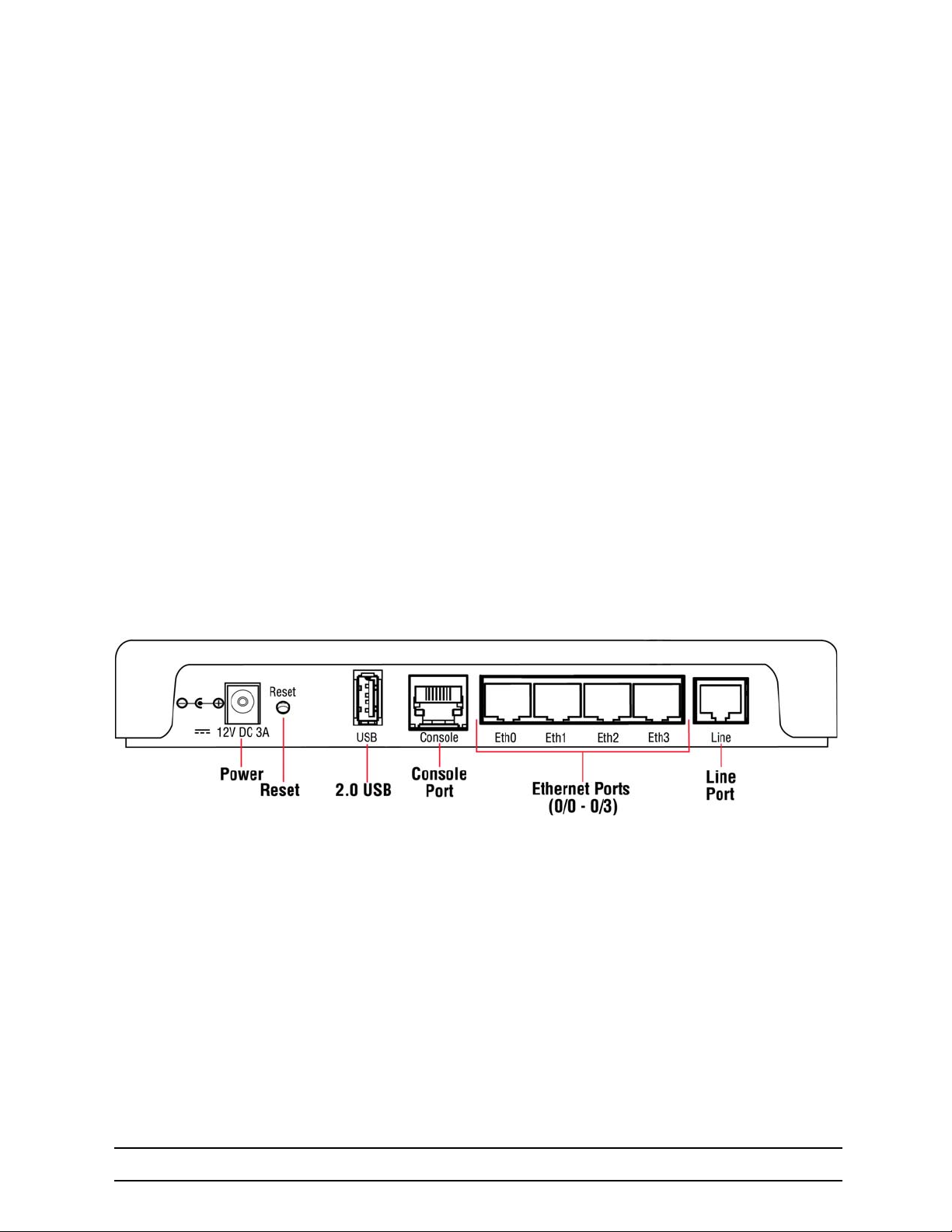
Note See figure 4 for the rear panel arrangements
2. Connect the Ethernet interface (refer to 3.5, “Connecting the Ethernet Interface” on page 22).
3. Connect the power plug (refer to 3.6, “Connecting Power” on page 23)
Figure 4 LB52XA-R2 rear panel options
724-746-5500 | blackbox.com
Page 20
Page 21
3 Installing the LB52XA-R2
3.3 CONNECTING THE LINE INTERFACE
Follow the steps below to connect the LB52XA-R2 interfaces.
1. To function properly, the two LB52XA-R2s must be connected together using twisted-pair, unconditioned, dry, metal wire, between 19 (0.9mm) and 26 AWG (0.4mm). Leased circuits that run through
signal equalization equipment are not acceptable.
2. The Ethernet Extender is equipped with a RJ-45 interface jack (Line), which conforms to the T568B
standard. As such, any standard Category 5e cable can be used to directly connect two extenders.
Depending on the extender model, it will have a two-wire, four-wire or eight-wire interface
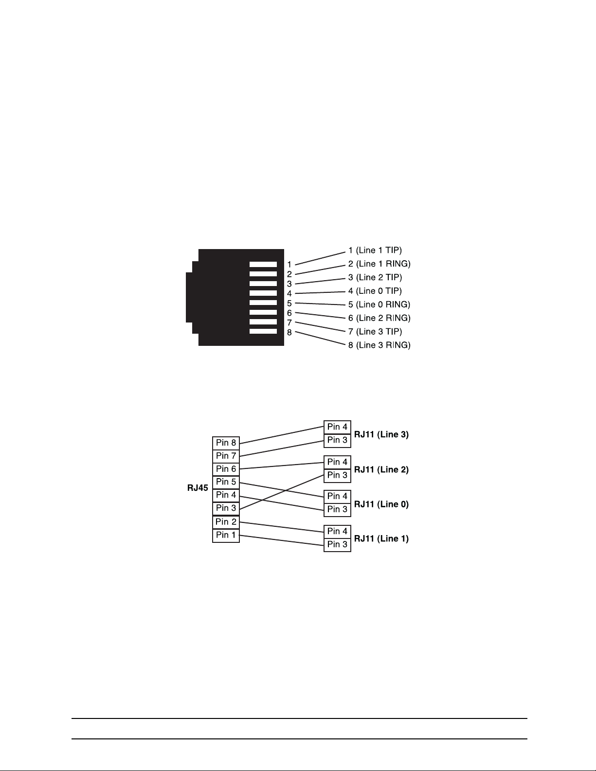
Observe the signal/pin relationship on the LB52XA-R2’s Line interface jack for each pair in figure 5
Figure 5 LB52XA-R2 (RJ-45) twisted pair line interface
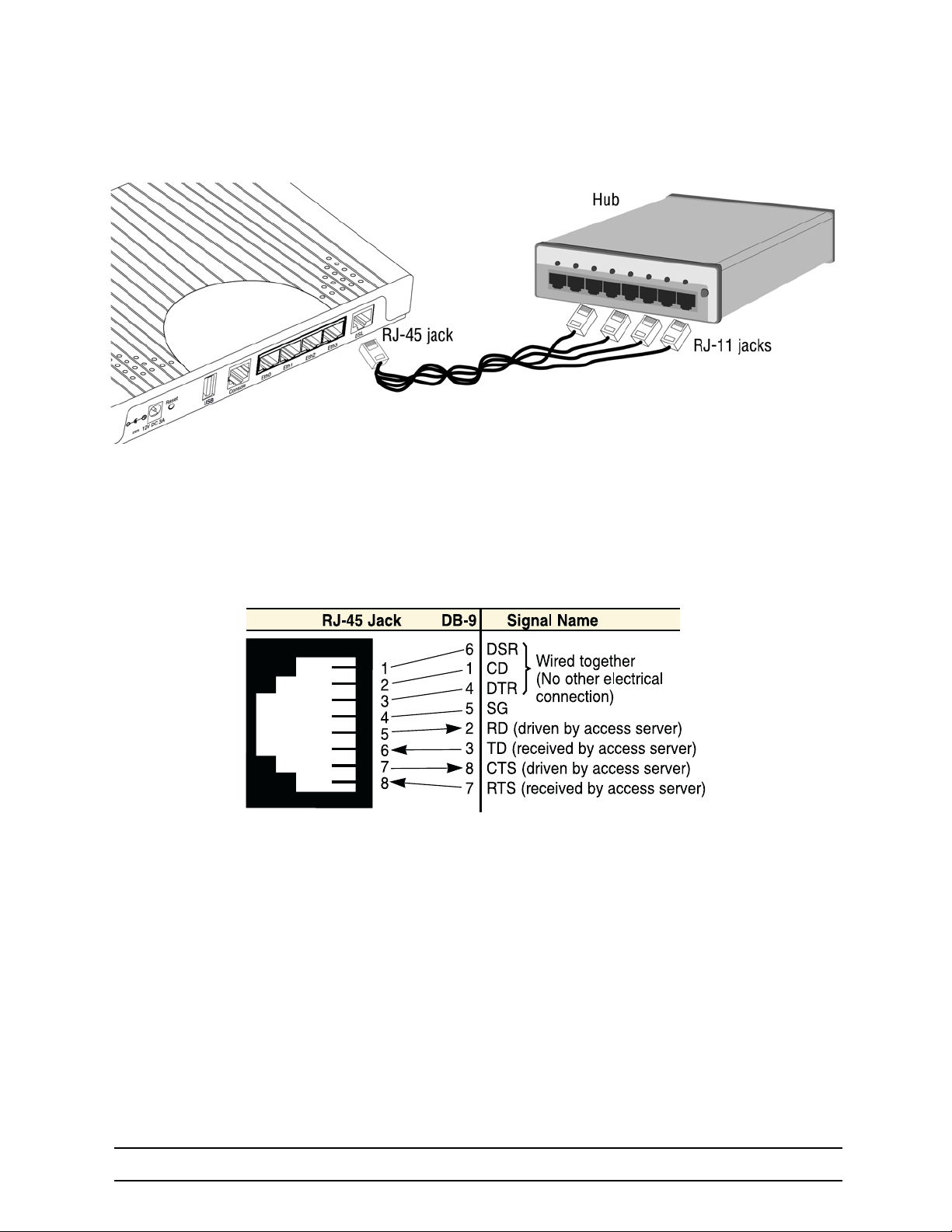
Figure 6 shows the proper way to wire a cable with a RJ-45 jack on one end and four RJ-11jacks on the
other.
Figure 6 Pin-out for two devices
724-746-5500 | blackbox.com
Page 21
Page 22
3 Installing the LB52XA-R2
Figure 7 RJ-45 to RJ-11 cable
3.4 CONNECTING CONSOLE INTERFACE
Install the supplied RJ-45-to-RJ-45 cable with the DB9-RJ45 adapter between the LB52XA-R2 RS-232
port and an open serial port on your computer. If you need to assemble your own cable, refer to the pin-out
diagram in
figure 8.
.
Figure 8 DB-9-to-RJ-45 cable diagram
3.5 CONNECTING THE ETHERNET INTERFACE
The Ethernet Extender has four unshielded RJ-45 Auto-MDIX10/100Base-T interfaces. These ports are
designed to connect directly to a 10/100Base-T device or network. You may connect this port to a hub or
PC using a straight through or crossover cable that is up to 328 ft. long.
724-746-5500 | blackbox.com
Page 22
Page 23

3 Installing the LB52XA-R2
3.6 CONNECTING POWER
The Ethernet Extender does not have a power switch, so it powers up as soon as it is plugged in.
The power connection is made via the barrel jack on the rear panel of the LB52XA-R2. No configuration is
necessary for the power supply.
An external AC or DC power supply is available separately. This connection is made via the barrel jack on
the rear panel of the LB52XA-R2. No configuration is necessary for the power supply.
DC power (supplied via the power supply jack to the LB52XA-R2) must meet the following requirements;
DC power supplied must be regulated 12VDC ±5%, 1.0A minimum. Center pin is +12V. The barrel type plug
has a 2.5/5.5/10mm I.D./O.D./Shaft Length dimensions.
724-746-5500 | blackbox.com
Page 23
Page 24

4 CONFIGURATION AND OPERATION
Chapter contents
4. Configuration and Operation.......................................................................................................24
4.1 Introduction................................................................................................................................ 25
4.2 Connect with SSH.......................................................................................................................25
4.3 Connect with Console .................................................................................................................25
4.4 Change the IP address (default: 192.168.200.10) ...................................................................... 25
4.5 Change the default username..................................................................................................... 25
4.6 Save the Configuration ...............................................................................................................25
4.7 Line Port Commands .................................................................................................................. 25
4.7.1 Local and Remote ......................................................................................................................25
4.7.2 Annex Type ................................................................................................................................ 26
4.7.3 Line Rate Configuration ............................................................................................................. 26
4.7.4 Modulation Scheme ................................................................................................................... 26
4.7.5 Line Ports ...................................................................................................................................26
4.7.6 Signal to Noise Ratio .................................................................................................................26
4.7.7 Description .................................................................................................................................26
4.7.8 Use Profile ................................................................................................................................. 26
4.7.9 Service Mode ............................................................................................................................. 26
4.7.10 Shutdown ................................................................................................................................... 27
4.7.11 Exit .............................................................................................................................................27
4.7.12 Show .......................................................................................................................................... 27
724-746-5500 | blackbox.com
Page 24
Page 25

4 Configuration and Operation
4.1 INTRODUCTION
You can connect a PC to configure the LB52XA-R2 using the CLI.
4.2 CONNECT WITH SSH
1. Connect the Ethernet cable.
2. Connect the power supply.
3. Connect via SSH to the default address 192.168.200.10
4. Login with the default username admin and no password.
4.3 CONNECT WITH CONSOLE
1. Connect the RS232 Console cable.
2. Connect the power supply.
3. Login with the default username admin and no password.
4.4 CHANGE THE IP ADDRESS (DEFAULT: 192.168.200.10)
Follow the command sequence below.
node~>enable
node~#configure
node~(cfg)#context ip router
node~(ctx-ip)[router]#interface LAN
node~(if-ip)[router.LAN]#no ipaddress 192.168.200.10/24
node~(if-ip)[router.LAN]#ipaddress <new address>/<new mask>
4.5 CHANGE THE DEFAULT USERNAME
The default username will be removed once a new one is created.
Follow the command sequence below.
node~>enable
node~#configure
node~(cfg)#superuser <username> password <password>
4.6 SAVE THE CONFIGURATION
Follow the command sequence below.
node~>enable
node~#configure
node~(cfg)#copy running-config startup-config
4.7 LINE PORT COMMANDS
4.7.1 LOCAL AND REMOTE
This will set the Ethernet Extender as Local or Remote. Local is typically used at the network, Remote is
typically used at the remote device or remote network. Your Black Box LB52XA-R2 when received in a 2pk
is already configured one LB52XA-R2 as Local and one LB52XA-R2 as Remote.
node(cfg) (prt-line) [0/0]#mode {local|remote}
724-746-5500 | blackbox.com
Page 25
Page 26

4 Configuration and Operation
4.7.2 ANNEX TYPE
Please consult support before changing this setting.
node~(pf)[<name>]# annex-type { b-g | a-f }
4.7.3 LINE RATE CONFIGURATION
This will increase the line rate of the LB52XA-R2. Your LB52XA-R2, by default, automatically selects the
optimal rate based on the distance (adaptive).
node(prt-line)[0/0]# payload-rate {adaptive [max <192..15296>] | <192..15296>}
4.7.4 MODULATION SCHEME
Note higher TC-PAM rates will increase maximum payload rates available but will decrease distance. Your
LB52XA-R2 is defaulted to automatically select the optimal setting. Please consult manual for rate reach
chart to determine your optimal setting if you choose to hard set this value. Higher TC-PAM rates are ideal
for shorter cable runs offering max symmetrical (upstream/downstream) speeds of 11.4 Mbps (TCPAM64)
and 15.3 Mbps (TCPAM128) per pair.
node(prt-line)[0/0]# tcpam {auto(16/32) | auto(64/128) | 16 | 32 | 64 | 128}
4.7.5 LINE PORTS
The configurations below are used to configure various aspects of the line port(s).
node~(cfg)# port line 0 0
4.7.6 SIGNAL TO NOISE RATIO
Configures the acceptable noise margin for adaptive rate. SNR is the relative strength of the line signal to
Noise ratio. 6dB is generally the lowest dB recommended in order for the modem to be able to sync. Gen
erally speaking, as overall bandwidth increases, your signal to noise ratio decreases. The higher the number the better. Your LB52XA-R2 is defaulted at 6 giving you the highest likelihood to connect.
node(prt-line)[0/0]# snr-margin <-10..22>
Below 6dB bad
6dB-10dB fair
11dB-20dB good
4.7.7 DESCRIPTION
This is the description of the port/line (line connection). (Ex: "This line goes to building 4") When entering a
description with spaces in the text, the description must be in quotations.
node~(prt-line)[0/0]# description <description>
4.7.8 USE PROFILE
Configures the acceptable noise margin for adaptive rate. SNR is the relative strength of the line signal to
Noise ratio. 6dB is generally the lowest dB recommended in order for the modem to be able to sync.
node~(prt-line)[0/0]# use profile <name>
-
4.7.9 SERVICE MODE
Configures the number of pairs (wires) you want to use. The LB52XA-R2 will default to the maximum number of wires available on your version of the LB522A-R2 (2-wire); LB524A-R2 (4-wire); LB528A-R2 (8-wire).
node~(prt-line)[0/0]# service-mode { 2-wire | 4-wire | 6-wire | 8-wire }
724-746-5500 | blackbox.com
Page 26
Page 27

4.7.10 SHUTDOWN
Disables or Enables port(s).
node~(prt-line)[0/0]# [no] shutdown
4.7.11 EXIT
Goes back to parent mode.
node~(prt-line)[0/0]# exit
4.7.12 SHOW
Displays all the configured options of the LB52XA-R2 line port(s)
node(cfg)# show prt-line 0
4 Configuration and Operation
724-746-5500 | blackbox.com
Page 27
Page 28

5 LB52XA-R2 BRIDGING CONTEXTS
Chapter contents
5. LB52XA-R2 Bridging Contexts ................................................................................................... 28
5.1 Configuration Task List.............................................................................................................. 29
5.2 Optional Tasks ............................................................................................................................ 29
5.3 Context Switch: HW Bridge......................................................................................................... 29
5.3.1 Switch Mode Groups .................................................................................................................29
5.3.2 Switch Mode VLANS .................................................................................................................. 29
5.3.3 Port Configuration ...................................................................................................................... 30
5.3.4 Bindings ..................................................................................................................................... 30
5.4 Context Bridge: SW Bridge Introduction ..................................................................................... 30
5.4.1 Bridge Groups ............................................................................................................................ 33
5.5 Line: Overview ............................................................................................................................ 33
5.5.1 Line Configuration Parameters .................................................................................................. 34
5.5.2 Mandatory Configuration List (local sets payload rate) .............................................................. 34
724-746-5500 | blackbox.com
Page 28
Page 29

5 LB52XA-R2 Bridging Contexts
5.1 CONFIGURATION TASK LIST
To properly configure the LB52XA-R2, perform the tasks described in the following sections:
•
Configure Ports: All your line and Ethernet ports must be configured (see page 33)
•
Configure Context Switch: Is it a VLAN application or unmanaged switch application (see page 29)
•
Configure Context Bridge: All traffic must run through the SW bridge (see page 30)
•
Configure Bridge Groups: Context Bridge must have at least one bridge group (see page 33)
•
Configure Bindings: Make sure ports, interfaces, and contexts are bound (see page 30)
5.2 OPTIONAL TASKS
•
Configure Context IP. See chapter 6, “IP Context Overview” on page 35
•
Configure IP Interface for Management Only. See chapter 6, “IP Context Overview” on page 35
5.3 CONTEXT SWITCH: HW BRIDGE
Context Switch is the hardware MAC switching (conceptual entity) support for the Embedded OS Device.
This functionality allows the unit to function as a managed or unmanaged layer 2 VLAN switch. Managing
your traffic flow with Context Switch commands will significantly enhance the performance especially when
handling the tagging/untagging of VLAN traffic. The switch is set by default as layer two unmanaged switch
with no VLAN support for passing transparent traffic.
Description
Switch Mode Groups Allows you to put Ethernet ports into isolation groups at the HW layer
Switch Mode VLANS Allows you to put the Ethernet ports into 802.1q VLAN trunk mode
5.3.1 SWITCH MODE GROUPS
By default the Switch mode is set for all Ethernet Ports to be in same isolation group on in the same switch.
This means that all of the Ethernet Ports are one switch and all traffic flow on all ports will follow the same
path. Switch mode groups also allow you to divide the switch into more than one switch device and this can
be used for traffic isolation. This is the best way to setup your device if you are not using VLAN traffic.
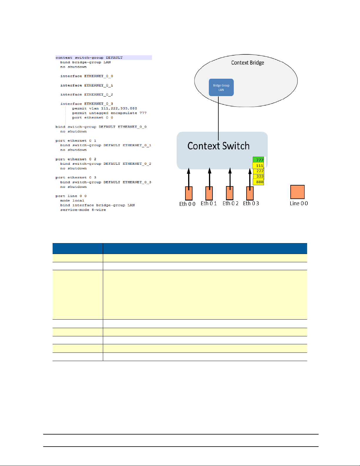
5.3.2 SWITCH MODE VLANS
If your network design includes the use of VLAN traffic it’s best to the put the switch into VLAN mode. This
mode allows you to decide if you want the port to be used as an “access port” or “trunk port” and the tag
ging/untagging can be performed at the HW layer. Tagging and Untagging of VLANS is an ideal way to isolate your traffic for purposes of higher level of security, QoS and or network monitoring for management
purposes
-
724-746-5500 | blackbox.com
Page 29
Page 30
5 LB52XA-R2 Bridging Contexts
Figure 9 Switch mode VLANS
5.3.3 PORT CONFIGURATION
Description
Configure Port
Arp Enable ARP
Enter ‘interface’ configuration mode
• Permit untagged- permit all traffic
Interface
Multicast Enable Multicast
VLAN Not supported (bind VLAN’s directly to the interface or port)
Shutdown
Session Create PPPoE session
No Disable features or reset to default behavior
• Permit untagged encapsulate- permit all untagged traffic and tag with VLAN ID
• Permit VLAN- Allow traffic tagged with VLAN ID
• Deny VLAN- Deny traffic tagged with VLAN ID
• Permit ALL- Permit all untagged traffic
5.3.4 BINDINGS
Bindings form the association between circuits or ports and the interfaces configured on a context. No user
data can flow on a circuit or Ethernet port until some higher-layer service is configured and associated with
it. Bindings are configured statically in the port configuration.
5.4 CONTEXT BRIDGE: SW BRIDGE INTRODUCTION
Context Bridge is the software MAC switching (conceptual entity) side of the Embedded OS Device. This
allows the configuration of the unit to be highly flexible and perform all the switching level functions that any
724-746-5500 | blackbox.com
Page 30
Page 31
5 LB52XA-R2 Bridging Contexts
normal switch can do but at a software or CPU level. This can be used like the context switch-group entity
to perform the same functions such as isolate, manage or dictate the traffic flow of all IP traffic at the MAC
layer. If you are unable or need a more complex configuration than the Context switch-group can perform
then you may need the flexibility of using software enabled bridge functions to get the job done.
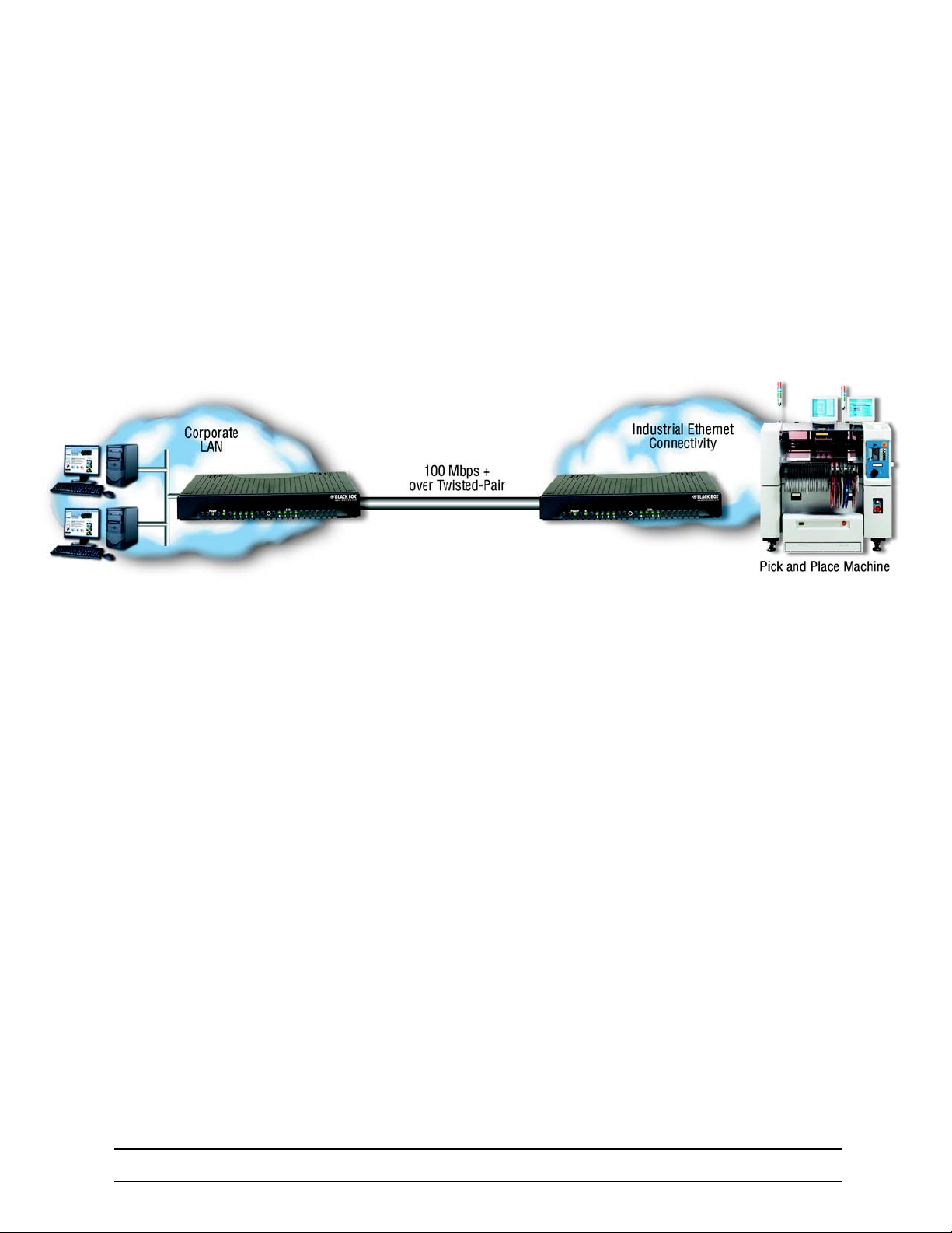
When setting up the device you must decide the best and most efficient way to pass traffic from the Ethernet Ports to the WAN (EFM) ports. In routed modes the traffic path will always be routed at layer 3 from one
interface to the other before it passes correctly. In the bridging mode all traffic will pass transparently
though either a context switch or context bridge. Context Bridge can be used in combination with Context IP
as you can see the in the example below. Bridging traffic is more efficient and easier to maintain when you
need to pass the traffic between two Embedded OS Devices that are on the same network, such as the
diagram below
.
Figure 10 Bridge Network
724-746-5500 | blackbox.com
Page 31
Page 32
5 LB52XA-R2 Bridging Contexts
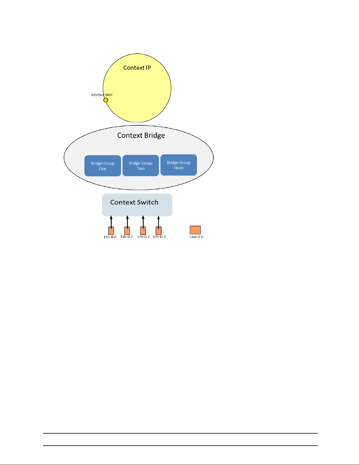
Context IP is your routing core. You
may configure as many interfaces as
needed. Remember to bind to the
correct interface
You are not limited to how many
bridge-groups you can create inside
of the Context bridge.
If you have VLAN’s on your network,
remember to configure
“switch mode vlans”
Figure 11 Breaking down OS concepts
724-746-5500 | blackbox.com
Page 32
Page 33

5 LB52XA-R2 Bridging Contexts
5.4.1 BRIDGE GROUPS
Description
Bridge Group Enters or creates a bridge-group
No Disable features or reset to default behaivior
Aging MAC table aging value in seconds
Arp Arp Enable
Filter
Mulitcast Enable Multicast
Session Create PPPoE session
Settap configure a bridge tap
Shutdown Shutdown the selected interface
STP Configure spanning tree
VLAN Enter a VLAN Configuration
Filter Command for MAC
• Permit{src | any}{dest | any}[VLAN ID]
5.5 LINE: OVERVIEW
Configuration details for creating a DSL or Line Connection. Connections can only be made between two
modems. These modems must have manual configurations to create a link.
Annex-type Must match on both modems
Mode
Payload Rate Local Payload Configuration
Service-mode Local Service-mode configuration
Must be opposites
• Example: Local <–> Remote
Description
724-746-5500 | blackbox.com
Page 33
Page 34

5 LB52XA-R2 Bridging Contexts
5.5.1 LINE CONFIGURATION PARAMETERS
Description
Annex-type Configure annex (must match peer)
Bind Interface, bridge-group
Description text information
Mode local and remote
Payoad-rate “adaptive” “max”
Service-mode 4 wire (2–4–8 wire support)
Snr-margin Max for line connection quality
Tcpam 16/32 64/128
VLAN Configures VLAN interface
5.5.2 MANDATORY CONFIGURATION LIST (LOCAL SETS PAYLOAD RATE)
Description
Mode Local or Remote
Annex type (must match other side)
Bind Must bind line port to bridge-group or interface
Service-mode Must match
Shutdown
724-746-5500 | blackbox.com
Page 34
Page 35

6 IP CONTEXT OVERVIEW
Chapter contents
6. IP Context Overview ................................................................................................................... 35
6.1 Introduction................................................................................................................................ 36
6.2 Packet Processing in the IP Context........................................................................................... 37
6.2.1 Classifier ....................................................................................................................................39
6.2.2 Network Address Port Translation (NAPT) ................................................................................39
6.2.3 Routing-table Selection .............................................................................................................. 39
6.2.4 Access Control Lists (ACL) ........................................................................................................39
6.2.5 Routing ....................................................................................................................................... 39
6.2.6 Packet Processing To/From Local Applications .........................................................................39
6.3 IP Context Overview Configuration Task List .............................................................................40
6.4 Planning Your IP Configuration................................................................................................... 40
6.4.1 IP Interface Related Information ................................................................................................ 40
6.4.2 QoS Related Information ........................................................................................................... 41
6.4.3 Configuring Physical Ports ......................................................................................................... 41
6.4.4 Creating and Configuring IP Interfaces ...................................................................................... 41
6.4.5 Configuring Packet Classification .............................................................................................. 41
6.4.6 Configuring Network Address Port Translation (NAPT) ............................................................. 41
6.4.7 Configuring Static IP Routing ..................................................................................................... 41
6.4.8 Configuring Access Control Lists (ACL) ..................................................................................... 42
6.4.9 Configuring Quality of Service (QoS) ......................................................................................... 42
724-746-5500 | blackbox.com
Page 35
Page 36
6 IP Context Overview
6.1 INTRODUCTION
This chapter outlines the OS Internet protocol (IP) context and its related components. You will get the fundamental understanding on how to set up your LB52XA-R2 to make use of IP related services.
The following sections describe the configuration steps necessary to put together certain IP services and
the references to the related chapters that explain the issue in more detail.
The IP context in the OS is a high level, conceptual entity that is responsible for all IP-related protocols and
services for data and voice. The IP context performs much of the same functions as a standalone IP router,
and since every context is defined by a name, the IP context is named ROUTER by default.
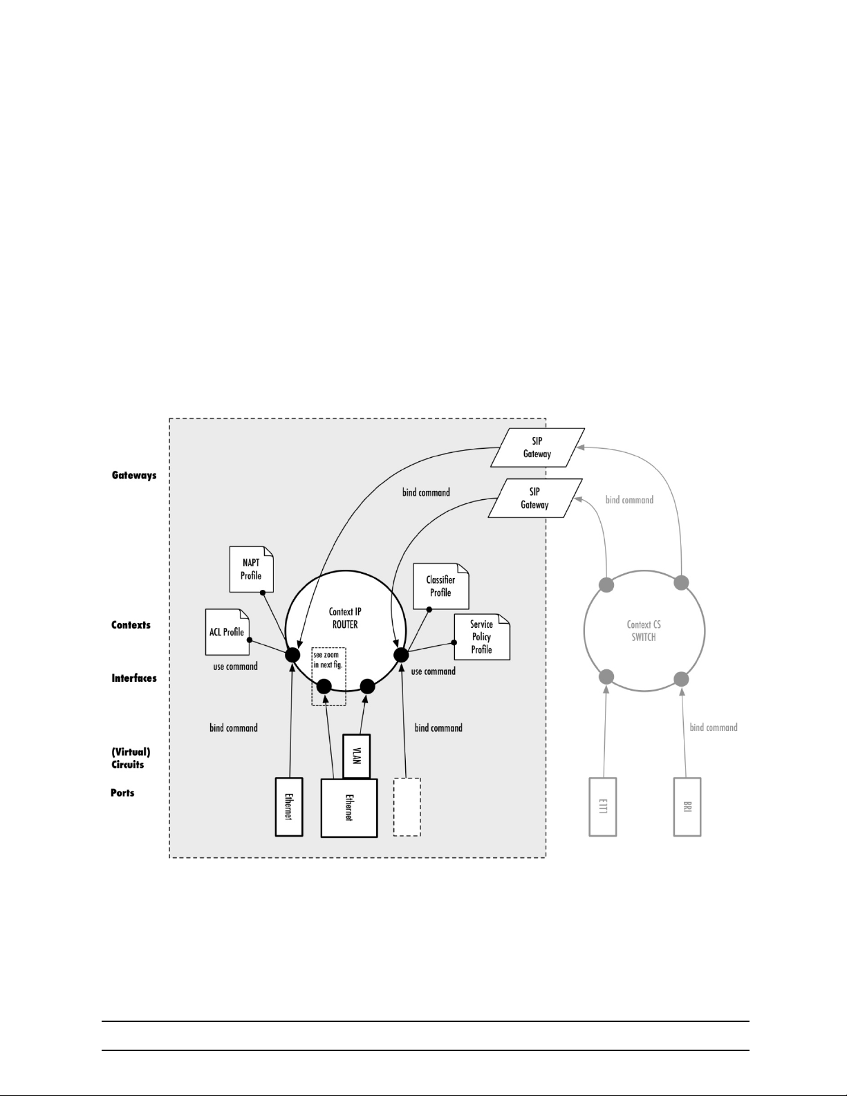
In figure 12 below, the IP context with all its related elements is contained within the area on the left, which
has a gray fill (find a short description of those elements below). The right side displays the related CS context, which communicates with the IP context via gateways. Since the CS context and its related components are not the subject of this chapter, they are illustrated in figure 12 with gray lines instead of black
ones.
Figure 12 IP context and related elements
The IP context contains the following entities:
•
Routing tables
•
Logical IP interface
•
Links to service profiles
724-746-5500 | blackbox.com
Page 36
Page 37

6 IP Context Overview
Since the IP context represents a virtual IP4 and IPv6 dual-stack router, it contains up to 251 routing tables
for static routes (not depicted in
are delivered to a local application (example, CLI, web server, SIP gateway) or routed via another IP interface to a remote network host.
The IP context may contain an arbitrary number of logical interfaces. Unlike other operating systems where
a network interface is identical to a physical port, we distinguish physical ports from logical interfaces. A
logical interface contains all IP-related configuration parameters that are common to all ports, such as the
IP address, for example. As depicted in
to one logical IP interface. Hence, each IP interface reflects the IP-protocol of a physical port or circuit.
Applications such as SIP gateways may also be bound to an IP interface. A top-down binding defines over
which IP interface (and hence over which physical port or circuit) an application communicates.
figure 12 on page 36). The routing tables decide whether received packets
figure 12 on page 36, a physical port or circuit is bound bottom-up
6.2 PACKET PROCESSING IN THE IP CONTEXT
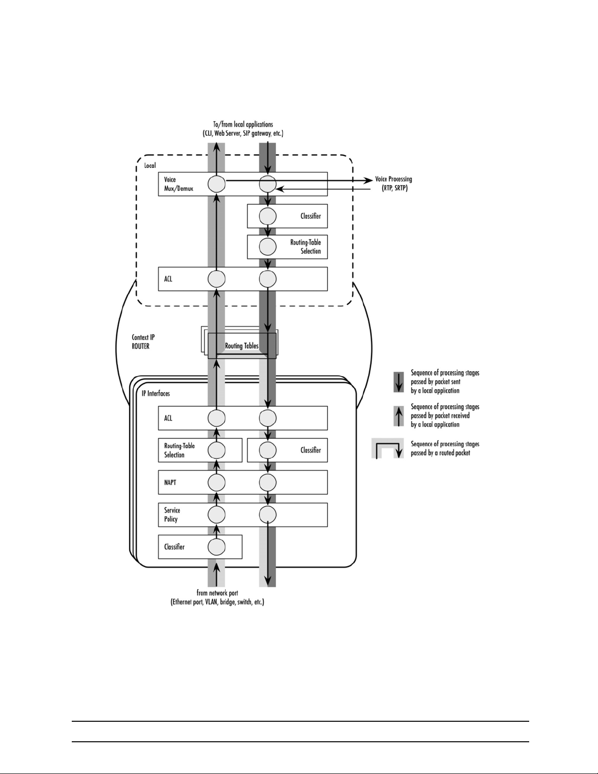
Several IP service profiles can be assigned to the individual logical interfaces in the context (see figure 12).
These profiles control the flow of packets through the router. They classify packet streams, control which
packets may enter/leave the device via Access Control Lists (ACL), perform Network and Port Address
Translation (NAPT) and deal with Quality-of-Service (QoS) information in packet headers.
Note that there is a different packet-processing chain for each interface depending on its configuration, i.e.,
each interface maintains its own configuration of how the packets are classified, a different ACL, etc. How
ever, to make having the same configuration on multiple interfaces easier, we moved the configuration
parameters to profiles. The use command attaches a profile to an interface, such that the same profile can
be used by different interfaces.
-
Figure 13 shows the journey of a packet through the IP context and the order in which the attached profiles
process the packet.
724-746-5500 | blackbox.com
Page 37
Page 38
6 IP Context Overview
Figure 13 Processing order of IP services attached to an IP interface
724-746-5500 | blackbox.com
Page 38
Page 39

6 IP Context Overview
6.2.1 CLASSIFIER
The classifier is the first profile that inspects an incoming packet. The classifier assigns a traffic class to
each packet. You can think of the traffic-class as if every packet in the router has a tag attached to it, on
which the classification can be noted. The traffic-class tags exist only inside the router, but layer 2 priority
bits (802.1pq class-of-service) and IP header type-of-service bits (TOS field) can be used to mark a spe
cific packet type for the other network devices. By default the traffic-class tag is default.
A powerful packet-matching filter in the classifier profile lets you inspect any combination of IP, UDP, TCP or
ICMP header fields and assign a traffic-class to the matching packet flow. For example, you may configure
to tag all UDP packets to a destination port between 5000 and 8000, and shorter than 500 bytes with the
traffic-class VOICE. The traffic-class tag can later be used in other IP service profiles, e.g., to filter packets
in the ACL or to do policy routing by selecting a routing-table based on the traffic-class.
6.2.2 NETWORK ADDRESS PORT TRANSLATION (NAPT)
After classification is done, the packet is handed over to the NAPT profile-if one is used on the current interface. Network Address Port Translation (NAPT), which is an extension to NAT, uses TCP/UDP ports in
addition to network addresses (IP addresses) to map multiple private network addresses to a single out
side address. Thus the NAPT profile may change the destination address and port of an incoming packet.
6.2.3 ROUTING-TABLE SELECTION
You may configure policy routing by selecting a different routing table based on some header fields of the
incoming packet. You may also use the traffic-class (tagged before in the Classifier) to make a routing-table
decision. For example, you may direct all packets tagged with the VOICE traffic-class to a separate routing
table while processing the other traffic with the default routing table.
-
-
Note The routing-table selection for an incoming packet is performed after NAPT, i.e., you will see the trans-
lated (private) addresses and ports
6.2.4 ACCESS CONTROL LISTS (ACL)
An access control list is a sequential collection of permit and deny conditions that apply to packets on a
certain interface. You can use the same packet-matching mechanism as in the classifier and the routingtable selection to decide whether the specified packet flow is permitted to enter the router or is rejected.
The ACL filter is passed after the routing decision has been made. This allows you to apply an ACL to an
input-output interface pair. For example, you may use a specific profile for all packets entering the router via
the LAN interface and leaving it over the DMZ interface.
6.2.5 ROUTING
Once a packet traversed all ingress packet filters (controlled by the attached profiles), the router decides
whether the packet is destined to an application of the gateway itself or shall be routed to a remote host.
For this purpose it performs a best-prefix match on the destination IP address in the routing-table, which
was previously selected. If no routing-table has been selected explicitly, the DEFAULT table is consulted.
If the packet is to be sent to a remote host, it traverses the egress filters of the IP interface (depicted in
figure 13), an egress ACL, another possibility to classify the packet, NAPT translations and finally, a ser-
vice-policy profile, which can be used to map an internal traffic-class to IP TOS field values.
6.2.6 PACKET PROCESSING TO/FROM LOCAL APPLICATIONS
If the packet is not sent to a remote host, and is destined for a local application (e.g. CLI, the web server, or
SIP signaling packets), another set of packet-processing filters is traversed after the routing decision has
been made. In particular, another ACL profile dedicated only for locally-terminated flows is passed. This
allows you to create specific ACL profiles to protect the local device while having different ACL profiles for
routed traffic.
724-746-5500 | blackbox.com
Page 39
Page 40

6 IP Context Overview
After passing the ACL, voice data packets (RTP/SRTP) are diverted to the voice processing engine
whereas the remaining traffic reaches one of the running service applications.
Packets that have been generated by applications on the device also traverse a set of packet-processing filters-a classifier to tag packets with a traffic-class, routing-table selection, and another outbound ACL for
locally-generated traffic.
As shown at the top of figure 13 on page 38, the local packet-processing filters are not attached to a specific logical IP interface. All packets to/from a local application rather pass the same set of filters. There is a
special local mode within the IP context in which classifier and ACL profiles for local applications can be
attached. The local mode also hosts routing-selection commands for locally-generated traffic (see chapter
13, “IP Routing” on page 87 for more information).
6.3 IP CONTEXT OVERVIEW CONFIGURATION TASK LIST
The following sections describe the basic tasks involved in IP context configuration. Many parameters have
acceptable default values, which in most cases do not need to be explicitly configured. Hence not all of the
configuration tasks below are required. Depending on your application scenario, some tasks are mandatory
while others are optional. The following tasks use a bottom-up approach, starting from the ports, followed
by the interfaces and up to the services running on the device. Read through the tasks in order to learn a
general understanding of the whole network before moving onto more detailed instructions.
•
Planning your IP configuration (see page 40)
•
Configuring physical ports (see page 41)
•
Creating and configuring IP interfaces (see page 41)
•
Configuring packet classification (see page 41)
•
Configuring Network Address Port Translation (NAPT) (see page 41)
•
Configuring static IP routing (see page 41)
•
Configuring Access Control Lists (ACL) (see page 42)
•
Configuring quality of service (see page 42)
6.4 PLANNING YOUR IP CONFIGURATION
The following subsections provide network connection considerations for Ethernet ports. Black Box recommends that you draw a network overview diagram displaying all neighboring IP devices. Do not begin configuring the IP context until you have completed the planning of your IP environment.
6.4.1 IP INTERFACE RELATED INFORMATION
Setting up the basic IP connectivity for your device requires at least the following information:
•
IP addresses used for Ethernet LAN and WAN ports
•
IP Subnet mask used for Ethernet LAN and WAN ports
•
Length for Ethernet cables
•
IP addresses of the central SIP registrar
•
IP addresses of the central PSTN gateway for SIP-based calls
724-746-5500 | blackbox.com
Page 40
Page 41

6 IP Context Overview
6.4.2 QOS RELATED INFORMATION
Check with your access service provider if there are any QoS-related requirements, which you need to
know prior to configuring OS QoS management. Check the following with your access service provider:
•
What is the dedicated bandwidth, which you have agreed with your access service provider?
•
How does your provider perform packet classification, e.g. which ToS bits have to be used to define
the supported classes of service?
6.4.3 CONFIGURING PHYSICAL PORTS
Port configuration includes parameters for the physical and data link layer, such as framing and encapsulation formats or media access control. Before any higher-layer user data can flow through a physical port,
you must associate that port with an interface within the IP context. This association is referred to as a bind
ing. For information and examples on how to configure ports, refer to the respective port type’s chapter.
6.4.4 CREATING AND CONFIGURING IP INTERFACES
The number and names of IP interfaces depend upon your application scenario. An interface is a logical
construct that encapsulates network-layer protocol and service information, such as IP addressing. There
fore, interfaces are configured as part of the IP context (the virtual router) and represent logical entities that
are only usable if a physical port (Ethernet) or circuit (VLAN) is bound to them.
An interface name can be any arbitrary string, but for ease of identification use self-explanatory upper-case
names that describe the use of the interface, e.g. LAN, WAN.
-
-
Several IP-related configuration parameters are necessary to define the behavior of such an interface. The
most obvious parameters are one or multiple IP addresses and the IP net masks that belong to them. Sev
eral profile types can also be attached to an IP interface to define how packets arriving on the interface or
leaving over it are processed.
6.4.5 CONFIGURING PACKET CLASSIFICATION
A classifier profile can be attached to each IP interface. It contains rules to match packet flows based on the
header fields of the packets and tag them with an internal traffic-class. This traffic-class is usually used in
conjunction with other services. For example, an ACL may have filter rules that drop all packets tagged with
a certain traffic-class, or policy routing may be configured to select a dedicated routing-table for a packet
flow of a given traffic-class. The OS tests packets against the classifier rules one by one. The first match
determines the traffic-class. Because the OS stops testing rules after the first match, the order of the classi
fier rules is critical. If no conditions match or if there is no classifier profile attached to an interface, the software tags receive packets with the DEFAULT traffic-class, whereas all packets generated by local
applications are tagged with the LOCAL-DEFAULT traffic-class, except generated RTP/SRTP packets,
which are tagged as LOCAL-VOICE.
Classifier profiles can be attached to several entities in the OS–on any local IP interface and in the local
mode of the IP context. In both places classifier profiles can be attached separately for inbound and out
bound packets.
6.4.6 CONFIGURING NETWORK ADDRESS PORT TRANSLATION (NAPT)
You can configure NAPT by creating a profile that is afterwards used on an explicit IP interface. In OS terminology, an IP interface uses a NAPT profile, as shown in figure 12 on page 36.
-
-
-
6.4.7 CONFIGURING STATIC IP ROUTING
The OS allows you to define static routing entries, which are destination-address-to-egress-interface mappings established by the network administrator prior to the beginning of routing. These mappings do not
change unless the network administrator alerts them. Algorithms that use static routes are simple to
724-746-5500 | blackbox.com
Page 41
Page 42

6 IP Context Overview
design, and work well in environments in which network traffic is relatively predictable and where network
design is relatively simple.
Routing entries are grouped in routing-tables. A set of route commands in the IP interface can be used to
select the routing-table for inbound traffic for different packet-header fields. The route command in the local
mode, within the IP context configures the routing-table to consult for locally-generated traffic. The OS tests
packets against the routing-table-selection rules one by one. The first match determines the routing-table to
use. Because the OS stops testing rules after the first match, the order of the routing-selection rules is crit
ical. If no conditions match or if there is no route command in the interface, the software uses the DEFAULT
routing table.
6.4.8 CONFIGURING ACCESS CONTROL LISTS (ACL)
Packet filtering helps to control packet movement through the network. Such control can help to limit network traffic and restrict network use by certain users or devices. An access control list is a sequential collection of permit and deny conditions that apply to packets on a certain interface. Access control lists can
be configured for all routed network protocols (IP, ICMP, TCP, UDP, and SCTP) to filter the packets of those
protocols as the packets pass through a device. The OS tests packets against the conditions in an access
list one by one. The first match determines whether the OS accepts or rejects the packet. Because the OS
stops testing conditions after the first match, the order of the conditions is critical. If no conditions match,
the software rejects the address.
6.4.9 CONFIGURING QUALITY OF SERVICE (QOS)
A service-policy profile can be attached to an IP interface to manage QoS for network traffic, as shown in
figure 12 on page 36. QoS refers to the ability of a network to provide improved service to selected network
traffic over various underlying technologies including Ethernet and 802.x type networks, as well as IProuted networks. In particular, QoS features provide improved and more predictable network service by
providing the following features:
-
•
Supporting dedicated bandwidth
•
Improving loss characteristics
•
Avoiding and managing network congestion
•
Shaping network traffic
•
Setting traffic priorities across the network
724-746-5500 | blackbox.com
Page 42
Page 43

7 COMMAND LINE INTERFACE (CLI)
Chapter contents
7. Command Line Interface (CLI) ...................................................................................................43
7.1 Introduction................................................................................................................................ 44
7.2 Command modes........................................................................................................................ 44
7.2.1 CLI prompt ................................................................................................................................. 44
7.2.2 Navigating the CLI .....................................................................................................................44
7.3 Command Editing ....................................................................................................................... 45
7.3.1 Command help ........................................................................................................................... 45
7.3.2 The No Form ..............................................................................................................................45
7.3.3 Command completion ................................................................................................................ 45
7.3.4 Command history ....................................................................................................................... 45
7.3.5 Command Editing Shortcuts ......................................................................................................46
724-746-5500 | blackbox.com
Page 43
Page 44

7 Command Line Interface (CLI)
7.1 INTRODUCTION
The primary user interface to the LB52XA-R2 is the command line interface (CLI). You can access the CLI
via the Black Box device console port or through a Telnet or SSH session. The CLI lets you configure the
complete LB52XA-R2 functionality. You can enter CLI commands online or as a configuration script in the
form of a text file. The CLI also includes monitoring and debugging commands. CLI commands are simple
strings of keywords and user-specified arguments.
This chapter gives an overview of the CLI and the basic features that allow you to navigate the CLI and edit
commands effectively. The following topics are covered:
•
Command Modes
•
Command Editing (see page 45)
7.2 COMMAND MODES
The CLI is composed of modes. There are three mode groups: the operator, the administrator mode and
the configure mode. The configuration mode group contains all of the remaining modes. A command mode
is an environment within which a group of related commands is valid. All commands are mode-specific, and
certain commands are valid in more than one mode. A command mode provides command line completion
and context help within the mode. The command modes are organized hierarchically.
7.2.1 CLI PROMPT
For interactive (online) sessions, the system prompt is displayed as:
devicename>
In the operator exec mode, the system prompt is displayed as:
devicename#
In the administrator exec mode and in the different configuration modes, the system prompt is displayed as:
devicename(mode)device#
Where:
•
devicename is the currently configured name of the Black Box device, the IP address or the hardware
type of the device that is being configured
•
mode is a string indicating the current configuration mode, if applicable.
•
name is the name of the instance of the current configuration mode
Example: the prompt in radius-client mode, assuming the devicename device and the instance deepblue
is:
device(radius)[deepblue]#
7.2.2 NAVIGATING THE CLI
•
Initial mode: When you initiate a session, you can log in with operator or administrator privileges.
Whichever login you use, the CLI is always set to operator exec (non-privileged exec) mode by default
upon startup. This mode allows you to examine the state of the system using a subset of the available
CLI commands.
•
System changes: In order to make changes to the system, the administrator exec (privileged exec)
mode must be entered. The enable user interface command is used for this purpose (the enable com
724-746-5500 | blackbox.com
-
Page 44
Page 45

7 Command Line Interface (CLI)
mand is only accessible if you are logged in as an administrator). Once in administrator exec mode,
all of the system commands are available to you.
•
Configuration: To make configuration changes, the configuration mode must be entered by using the
configure command in the administrator exec mode.
•
Changing Modes: The exit command moves the user up one level in the mode hierarchy (the same
command works in any of configuration modes). For example, when in pvc configuration mode, typing
exit will take you to framerelay configuration mode.
The exit command terminates a CLI session when typed from the operator exec mode.
A session can also be terminated by using the logout command within any mode.
7.3 COMMAND EDITING
7.3.1 COMMAND HELP
To see a list of all CLI commands available within a mode, type a question mark <?> or the <tab> key at
the system prompt in the mode of interest. A list of all available commands is displayed. Commands that
have become available in the current mode are displayed at the bottom of the list, separated by a line.
Commands from higher hierarchy levels are listed at the top.
You can also type the question mark or the <tab> key while in the middle of entering a command. Doing so
displays the list of allowed choices for the current keyword in the command. Liberal use of the question
mark functionality is an easy and effective way to explore the command syntax.
7.3.2 THE NO FORM
Almost every command supports the keyword no. Typing the no keyword in front of a command disables
the function or “deletes” a command from the configuration. For example, to enable the DHCP server trace
tool, enter the command debug dhcp-server. To subsequently disable the DHCP server trace, enter the
command no debug dhcp-server.
7.3.3 COMMAND COMPLETION
You can use the <tab> key in any mode to carry out command completion. Partially typing a command
name and pressing the <tab> key causes the command to be displayed in full up to the point where a fur
ther choice has to be made. For example, rather than typing configure, typing conf and pressing the <tab>
key causes the CLI to complete the command at the prompt. If the number of characters is not sufficient to
uniquely identify the command, the CLI will provide a list with all commands starting with the typed charac
ters. For example, if you enter the string co in the configure mode and press <tab>, the selections config-
ure, copy, and context are displayed. The CLI may be configured to automatically complete commands
without pressing the <tab> key. This will only happen if a unique completion option exists.
Command Purpose
[no] cli auto-completion Enable or disable CLI automatic command completion.
7.3.4 COMMAND HISTORY
The OS maintains a list of previously entered commands that you can go through by pressing the <uparrow> and <down-arrow> keys, and then pressing <enter> to enter the command. The show history
command displays a list of the commands you can go through by using the arrow keys.
-
-
724-746-5500 | blackbox.com
Page 45
Page 46

7 Command Line Interface (CLI)
7.3.5 COMMAND EDITING SHORTCUTS
The OS CLI provides a number of command shortcuts that facilitate editing of the command line. Command editing shortcuts are summarized below. The syntax <Ctrl>-<p> means press the <p> key while
holding down the keyboard’s control key (sometimes labeled Control, Ctl, or Ctrl, depending on the key
board and operating system of your computer). <Esc>-<f> is handled differently; press and release the
escape key (often labeled Esc on many keyboards) and then press the <f> key.
Keyboard Description
<Ctrl>-<p> or <up-arrow> Recall previous command in the command history.
<Ctrl>-<n> or <down-arrow> Recall next command in the command history.
<right-arrow> Move cursor forward one character.
<left-arrow> Move cursor backward one character.
<Esc>-<f> Move cursor forward one word.
<Esc>-<b> Move cursor backward one word.
<Ctrl>-<a> Move cursor to beginning of line.
<Ctrl>-<e> Move cursor to end of line.
<Ctrl>-<k> Delete to end of line.
<Ctrl>-<u> Delete to beginning of line.
<Ctrl>-<d> Delete character.
<Ctrl>-<c> Quit editing the current line.
Insert a code to indicate to the system that the keystroke immediately following
should be treated as normal text, not a CLI command.
<Ctrl>-<v>
For example, pressing the question mark <?> character in the CLI prints a list
of possible tokens. If you want to use the “?” in a configuration command, e.g.
to enter a regular expression, press Ctrl-v immediately followed by the question mark <?>.
-
724-746-5500 | blackbox.com
Page 46
Page 47

8 ACCESSING THE CLI
Chapter contents
8. Accessing the CLI ....................................................................................................................... 47
8.1 Introduction................................................................................................................................ 48
8.2 Accessing the CLI task list ..........................................................................................................48
8.3 Accessing via the console port ...................................................................................................49
8.3.1 Console port procedure ............................................................................................................. 49
8.4 Accessing via a secure configuration session over SSH ............................................................ 49
8.4.1 Accessing via a Telnet session .................................................................................................. 50
8.4.2 Telnet Procedure ....................................................................................................................... 50
8.5 Using an alternate TCP listening port for the Telnet or SSH server ...........................................50
8.6 Disabling the Telnet or SSH server.............................................................................................50
8.7 Logging on .................................................................................................................................. 50
8.8 Selecting a secure password ......................................................................................................51
8.9 Password encryption...................................................................................................................52
8.9.1 Factory preset superuser account .............................................................................................52
8.10 Configuring operators, administrators, and superusers ..............................................................52
8.10.1 Creating an operator account ....................................................................................................52
8.10.2 Creating an administrator account ............................................................................................. 53
8.10.3 Creating a superuser account .................................................................................................... 53
8.11 Displaying the CLI version .......................................................................................................... 54
8.12 Displaying account information ...................................................................................................54
8.13 Checking identity and connected users ...................................................................................... 54
8.14 Command index numbers ...........................................................................................................55
8.15 Ending a Telnet, SSH or console port session ........................................................................... 56
8.16 Showing command default values ..............................................................................................57
724-746-5500 | blackbox.com
Page 47
Page 48

8 Accessing the CLI
IMPORTANT
8.1 INTRODUCTION
The LB52XA-R2 is designed for remote management and volume deployment. The management and configuration of LB52XA-R2 is therefore based on IP network connectivity. Once an LB52XA-R2 is connected
to, and addressable in, an IP network, you can remotely perform all configuration, management, and main
tenance tasks.
This chapter describes the procedures for entering commands via the command line interface (CLI), to obtain
help, to change operator mode, and to terminate a session. You can access the LB52XA-R2 as follows:
•
Directly, via the console port (if available)
•
Remotely, via the IP network (by using a Telnet or SSH application)
The ports available for connection and their labels are shown in the getting started guide that came with
your unit. Remember that the CLI supports a command history and command completion. By scrolling with
the up and down arrow keys, you can find many of your previously entered commands. Another time-sav
ing tool is command completion. If you type part of a command and then press the <tab> key, the OS shell
will present you with either the remaining portion of the command or a list of possible commands. These
features are described in chapter
server can be disabled if desired.
7, “Command Line Interface (CLI)” on page 43. The telnet and SSH
Although the OS supports concurrent sessions via SSH or the console
port, we do not recommend working with more than one session to
configure the LB52XA-R2. However, using one session for configura
tion and another for debugging is a good idea.
-
-
-
8.2 ACCESSING THE CLI TASK LIST
The following sections describe the basic tasks involved in accessing the command line interface. Depending on your application scenario, some tasks are mandatory while others could be optional.
•
Accessing via the console port (see page 49)
•
Accessing via a SSH session (see page 50)
•
Using an alternate TCP listening port for the SSH server (see page 50)
•
Disabling the SSH server (see page 50)
•
Logging on (see page 50)
•
Selecting a secure password (see page 51)
•
Configuring operators and administrators (see page 52)
•
Displaying the CLI version (see page 54)
•
Switching to another log-in account (see page 54)
•
Checking identity and connected users (see page 54)
•
Ending a SSH or console port session (see page 56)
724-746-5500 | blackbox.com
Page 48
Page 49
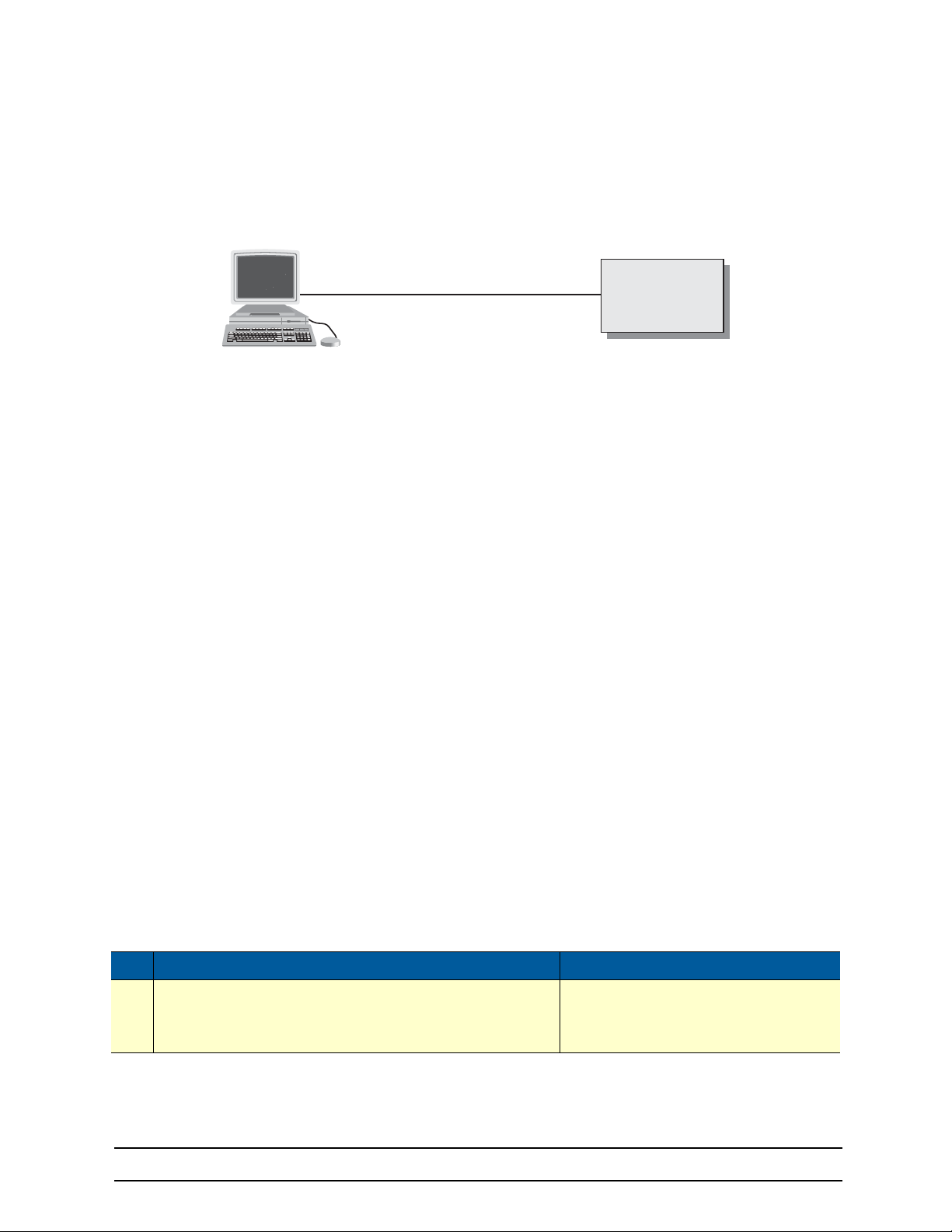
8 Accessing the CLI
Node
Node
Console
Host
Serial interface
8.3 ACCESSING VIA THE CONSOLE PORT
If a console port is available, the host computer can be connected directly to it with a serial cable (see
figure 14). The host must use a terminal emulation application that supports serial interface communica-
tion.
Figure 14 Setup for initial configuration via the console port
Note You do not need to configure IP settings if you access the Black Box device via the console port.
8.3.1 CONSOLE PORT PROCEDURE
Before using the CLI to enter configuration commands, do the following:
1. Set up the hardware as described in the getting started guide.
2. Configure your serial terminal as described in the getting started guide.
3. Connect the serial terminal to your Black Box device. Use a serial cable according to the description in
the getting started guide included with your Black Box device.
4. Power on your device. A series of boot messages are displayed on the terminal screen. At the end of
the boot sequence, press the <return> key and the login screen will be displayed. Proceed with logging
in.
8.4 ACCESSING VIA A SECURE CONFIGURATION SESSION OVER SSH
SSH is the most commonly used and recommended method for connecting to a Black Box device. A partial
implementation of secure shell according RFC 4251, RFC 4252, RFC 4253 and RFC 4254 is provided. It is
possible to open a secure configuration session over SSH to a Black Box device.
Note The copy tftp and http functions are still insecure!
The SSH Transport Layer supports the following Algorithms: “ssh-rsa” or ‘ssh-dsa” public key for signing,
“diffie-hellmann-group1-sha1” and “diffie-hellmann-group14-sha1” for key exchange, “3des-cbc”, “aes256cbc” and “aes128-cbc” for encryption, “hmac-sha1” and “hmac-md5” for data integrity. For user authentica
tion, only the method “password” is supported. On the Connection Layer, only the request for an interactive
command shell is supported. After the first startup of the OS, the RSA or DSA server host key is going to be
calculated. The RSA or DSA server host key is calculated only once and always remains the same.
Mode: Configure
Step Command Purpose
Set the AAA profile which is going to be
1 device(cfg)#terminal ssh use auth <AAA profile name>
used for user authentication. The AAA pro
file “default” is used when another profile is
not specified.
-
-
724-746-5500 | blackbox.com
Page 49
Page 50

8 Accessing the CLI
8.4.1 ACCESSING VIA A TELNET SESSION
It is way faster than console access. The Telnet host accesses the LB52XA-R2 via its network interface.
Note If the IP configuration of the Ethernet port (LAN port) is not known or is incorrectly configured, you will
have to use the console interface.
8.4.2 TELNET PROCEDURE
Before you begin to use the CLI to input configuration commands, do the following:
1. Set up the Black Box device as described in the getting started guide included with your device.
2. Connect the host (PC) or hub to the Black Box device as described in the getting started guide.
3. Power on your device and wait until the Run LED lights.
4. Open a Telnet session to the IP address shown in the getting started guide.
5. Proceed with logging in.
8.5 USING AN ALTERNATE TCP LISTENING PORT FOR THE TELNET OR SSH
SERVER
The following command defines an alternate listening port for the telnet or SSH server.
Mode: Configure
Step Command Purpose
1 device(cfg)# terminal [telnet | ssh] port <port>
Uses TCP port <port> for accepting telnet or
connections
SSH
8.6 DISABLING THE TELNET OR SSH SERVER
The telnet or SSH server can be disabled using the following command.
Mode: Configure
Step Command Purpose
1 device(cfg)# no terminal [telnet | ssh] Disables the telnet or SSH server
8.7 LOGGING ON
Accessing the LB52XA-R2 via the local console port or via a Telnet session opens a login screen. The following description of the login process is based on a Telnet session scenario but is identical to that used
when accessing via the local console port.
The opening Telnet screen you see resembles that shown below. The window header bar shows the IP
address of the LB52XA-R2.
724-746-5500 | blackbox.com
Page 50
Page 51

8 Accessing the CLI
IMPORTANT
A factory preset superuser account with name admin and an empty password is available when you first
access the unit. For that reason, use the name admin after the login prompt and simply press the <enter>
key after the password prompt.
$ telnet 172.16.54.79
Trying 172.16.54.79…
Connected to 172.16.54.79.
Escape character is '^]'.
Release: 3.1.0 2013/01/20
OS login: admin
Password:
OS >
Upon logging in you are in operator execution mode, indicated by the “>” as command line prompt. Now
you can enter system commands.
Note Details on the screen, such as the IP address in the system prompt and window header bar, may be dif-
ferent on your unit.
You are responsible for creating a new administrator account to maintain system security. Black Box accepts no responsibility for losses or
damage caused by loss or misuse of passwords. Please read the fol
lowing sections to secure your network equipment properly.
-
8.8 SELECTING A SECURE PASSWORD
It is not uncommon for someone to try to break into (often referred to as hacking) a network device. The
network administrator should do everything possible to make the network secure. Carefully read the ques
tions below and see if any applies to you:
•
Do your passwords consist of a pet’s name, birthdays or names of friends or family members, your
license plate number, social security number, favorite number, color, flower, animal, and so on?
•
Do you use the same password repeatedly? (Example: Your ATM PIN, cell phone voice mail, house
alarm setting code, etc.)
•
Could your password or a portion thereof be found in the dictionary?
•
Is your password less than six characters long?
To prevent unauthorized access, you should select passwords that are not dictionary words or any of the
above-mentioned examples. Every password should be at least 6 characters long and include at least one
capital letter, one number, and one lowercase letter.
A good example of a password is: 3Bmshtr
You are probably asking yourself, “How am I going to remember that?” It’s easy, the password above is an
acronym taken from: “three blind mice, see how they run.” Making a good password is that easy—but
please, don’t use the above example password for your LB52XA-R2!
-
724-746-5500 | blackbox.com
Page 51
Page 52

8 Accessing the CLI
8.9 PASSWORD ENCRYPTION
Unencrypted passwords can be stolen by hackers using protocol analyzers to scan packets or by examining the configuration file—to protect against that type of theft, the OS encrypts passwords by default.
Encryption prevents the password from being readable in the configuration file.
•
Plain text
•
Encrypted text (for example, the password mypassword always appears in encrypted form as
HUAvCYeILWZz3hQvS0IEpQ== encrypted when doing a show command)
The command show running-config always displays the passwords in encrypted format. To encrypt a pass-
word, enter the password in plain format and retrieve the encrypted format from the running-config or store
it permanently into the startup-config (with the command copy running-config startup-config).
8.9.1 FACTORY PRESET SUPERUSER ACCOUNT
The OS contains a factory preset superuser account with the name admin (no passwords). When a new
superuser account has been defined in the configuration, the preset admin account will delete after reboot.
You can create more than one superuser account, but there has to be at least one superuser account
defined. If, for some reason, the last superuser account is deleted, the factory preset administration
account with the name admin and an empty password is automatically recreated.
8.10 CONFIGURING OPERATORS, ADMINISTRATORS, AND SUPERUSERS
8.10.1 CREATING AN OPERATOR ACCOUNT
Operators do not have the privileges to run the enable command and therefore cannot modify the system
configuration. Operators can view partial system information.
Creating a new operator account is described in the following procedure:
Mode: Operator execution
Step Command Purpose
1 device>enable Enters administration execution mode
2 device#configure Enters configuration mode
3 device(cfg)# operator name password password
4 copy running-config startup-config
Creates a new operator account name and pass-
word password
Saves the change made to the running configuration of the Black Box device, so that it will be used
following a reload
Example: Create an operator account
The following example shows how to add a new operator account with a login name support and a matching password of s4DF&qw. The changed configuration is then saved.
device>enable
device#configure
device(cfg)#operator support password s4DF&qw
device(cfg)#copy running-config startup-config
724-746-5500 | blackbox.com
Page 52
Page 53
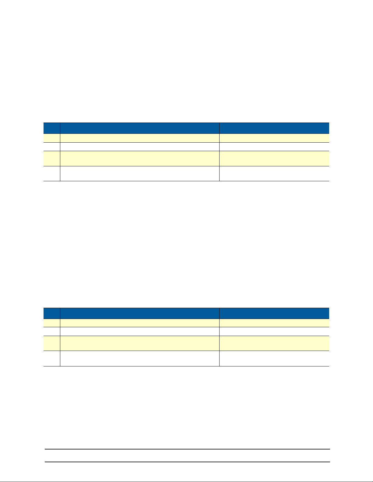
8 Accessing the CLI
8.10.2 CREATING AN ADMINISTRATOR ACCOUNT
Administrators can run the enable command and access additional information within the OS configuration
modes. Therefore administrators can modify the system configuration, as well as view all relevant system
information.
Creating a new administrator account is described in the following procedure:
Mode: Operator execution
Step Command Purpose
1 device>enable Enters administration execution mode
2 device#configure Enters configuration mode
3 device(cfg)# administrator name password password
4 device(cfg)#copy running-config startup-config
Example: Create an administrator account
The following example shows how to add a new administrator account with a login name super and a
matching password Gh3*Ke4h.
device>enable
device#configure
device(cfg)#administrator super password Gh3*Ke4h
device(cfg)#copy running-config startup-config
Creates a new administrator account name
and password password
Permanently stores the new administrator
account parameters.
8.10.3 CREATING A SUPERUSER ACCOUNT
Superusers can run the enable command and access additional information within the OSOS configuration
modes. Therefore, superusers can modify the system configuration, as well as view all relevant system
information. Superusers can also create new users (whereas administrators do not have that functionality).
Creating a new superuser account is described in the following procedure:
Mode: Operator execution
Step Command Purpose
1 device>enable Enters administration execution mode
2 device#configure Enters configuration mode
3 device(cfg)# superuser name password password
4 device(cfg)#copy running-config startup-config
Creates a new superuser account name and
password password
Permanently stores the new superuser
account parameters.
Example: Create a superuser account
The following example shows how to add a new superuser account with a login name super and a matching password Gh3*Ke4h.
device>enable
device#configure
device(cfg)#superuser super password Gh3*Ke4h
device(cfg)#copy running-config startup-config
724-746-5500 | blackbox.com
Page 53
Page 54
8 Accessing the CLI
8.11 DISPLAYING THE CLI VERSION
This procedure displays the version of the currently running CLI.
Mode: Operator execution
Step Command Purpose
1 device>show version cli Displays the CLI version
Example: Displaying the CLI version
The following example shows how to display the version of the current running CLI on your device, if you
start from the operator execution mode.
device>show version cli
CLI version: 3.00
8.12 DISPLAYING ACCOUNT INFORMATION
You can use the show command to display information about existing administrator and operator accounts.
This command is not available for an operator account.
The following procedure describes how to display account information:
Mode: Administrator execution
Step Command Purpose
1 device#show accounts Displays the currently-configured administrator and operator accounts.
Example: Display account information
The following example shows how to display information about existing administrator and operator
accounts.
device#show accounts
# UserName AccessLevel Status
0 super superuser (logged out:0)
1 admin administrator (logged out:0)
2 op operator (logged out:0)
8.13 CHECKING IDENTITY AND CONNECTED USERS
The who command displays who is logged in or gives more detailed information about users. Depending
on the execution mode, the command displays varying information. In administrator execution mode, the
command output is more detailed and shows information about the ID, user name and location. In operator
execution mode, only the user name being used at the moment is reported, which helps checking the iden
tity.
Mode: Administrator or operator execution
Step Command Purpose
1 OS(cfc)#who
or
OS>who Shows the user login identity
Shows more detailed information about the users ID, name, state, idle time and
location
-
724-746-5500 | blackbox.com
Page 54
Page 55

8 Accessing the CLI
Example: Checking identity and connected users
The following example shows how to report who is logged in or more detailed information about users,
depending on the execution mode in which you are working.
Used in administrator execution mode:
OS(cfg)#who
# User Name Login Time Location
0 admin 01/01/2000 00:08:59 console
1 admin 01/01/2000 00:11:36 telnet 172.16.54.135:55404
Used in operator execution mode:
OS>who
You are operator support
8.14 COMMAND INDEX NUMBERS
A command index number (indicated by the boldface 1, 2, and 3 index numbers in the example below) indicates the position of a command in a list of commands (that is, a command with index 1 will appear higher
in the configuration file than one with index 3).
192.168.1.1(pf-voip)[default]#show running-config
...
profile voip default
codec 1 g711ulaw64k rx-length 20 tx-length 20
codec 2 g711alaw64k rx-length 20 tx-length 20
codec 3 g723-6k3 rx-length 30 tx-length 30
dejitter-max-delay 200
...
Commands that make use of index numbers always show the index in the running config. However, the
index can be omitted when entering the command. If you enter such a command with an index, it is
inserted into list at the position defined by the index. If you enter such a command without an index, it is
placed at the bottom of the list. Also, you can change a commands position in a listing (moving it up or
down in the list) by changing its index number.
Example 1: Moving the G.723 codec from position 3 in the list to position 1 at the top of the list.
Listing before changing the G.723 codec index number:
profile voip default
codec 1 g711ulaw64k rx-length 20 tx-length 20
codec 2 g711alaw64k rx-length 20 tx-length 20
codec 3 g723-6k3 rx-length 30 tx-length 30
dejitter-max-delay 200
...
Listing after changing index number:
192.168.1.1(pf-voip)[default]#codec 3 before 1
192.168.1.1(pf-voip)[default]#show running-config
...
profile voip default
codec 1 g723-6k3 rx-length 30 tx-length 30
codec 2 g711ulaw64k rx-length 20 tx-length 20
codec 3 g711alaw64k rx-length 20 tx-length 20
dejitter-max-delay 200
...
724-746-5500 | blackbox.com
Page 55
Page 56

8 Accessing the CLI
Note Succeeding indexes are automatically renumbered.
Example 2: Moving the G.723 codec back position 3
This command moves the G.723 codec from the top to third place. As a result, the other two codecs move
up in the list as their indexes are automatically renumbered to accommodate the new third-place codec.
192.168.1.1(pf-voip)[default]#codec 1 after 3
192.168.1.1(pf-voip)[default]#show running-config
...
profile voip default
codec 1 g711ulaw64k rx-length 20 tx-length 20
codec 2 g711alaw64k rx-length 20 tx-length 20
codec 3 g723-6k3 rx-length 30 tx-length 30
dejitter-max-delay 200
...
Example 3: Inserting a codec at a specific position in the list.
This command assigns the G.729 codec the index number 1 so the codec appears at the top of the list.
192.168.1.1(pf-voip)[default]#codec 1 g729 tx-length 30 rx-length 30 silence-sup-
pression
192.168.1.1(pf-voip)[default]#show running-config
...
profile voip default
codec 1 g729 rx-length 30 tx-length 30 silence-suppression
codec 2 g711ulaw64k rx-length 20 tx-length 20
codec 3 g711alaw64k rx-length 20 tx-length 20
codec 4 g723-6k3 rx-length 30 tx-length 30
dejitter-max-delay 200
...
8.15 ENDING A TELNET, SSH OR CONSOLE PORT SESSION
Use the logout command in the operator or administration execution mode to end a Telnet or console port
session. To confirm the logout command, you must enter yes on the dialog line as shown in the example
below.
Mode: Operator execution
Step Command Purpose
1 device>logout Terminates the session after a confirmation by the user.
Example: End a Telnet or console port session
The following example shows how to terminate a session from the administrator execution configuration
mode.
device>logout
Press 'yes' to logout, 'no' to cancel:
After confirming the dialog with “yes”, the Telnet session is terminated.
Note Using the command
sion, but without any confirmation dialog.
exit
in the operator execution mode also terminates a Telnet or console port ses-
724-746-5500 | blackbox.com
Page 56
Page 57
8 Accessing the CLI
8.16 SHOWING COMMAND DEFAULT VALUES
If a command is set to its default value, it is not displayed in the running-config in order to make it more
readable. There are a few exceptions to this rule. The command cli config defaults makes commands also
appear in the running-config that are set to default values. no cli config defaults turns it off.
Step Command Purpose
1 device>enable Enters administration execution mode
2 device#configure Enters configuration mode
3 device(cfg)# superuser name password password
4 device(cfg)# cli config defaults
Creates a new superuser account name and
password password
Generate a command even if it reflects the
default setting (Default: Disabled)
724-746-5500 | blackbox.com
Page 57
Page 58

9 SYSTEM IMAGE HANDLING
Chapter contents
9. System Image Handling.............................................................................................................. 58
9.1 Introduction................................................................................................................................ 59
9.2 System image handling task list..................................................................................................59
9.2.1 Displaying system image information ........................................................................................ 59
9.2.2 Copying system images from a network server to Flash memory ............................................. 60
724-746-5500 | blackbox.com
Page 58
Page 59
9 System Image Handling
9.1 INTRODUCTION
System image handling management is a complex and feature rich system allowing a user to perform various upgrades on the devices. It allows a user to perform full upgrades and partial upgrades. It allows to
upgrade system configuration seamlessly. The upgrades tasks are supported both from the CLI and WMI.
You can copy files to flash from TFTP and local flash space. You can also upgrade from HTTP.
9.2 SYSTEM IMAGE HANDLING TASK LIST
To load and maintain system images, perform the tasks described in the following sections:
•
Displaying system image information
•
Copying system images from a network server to the Flash memory
•
Copying system configuration files to flash memory
9.2.1 DISPLAYING SYSTEM IMAGE INFORMATION
This procedure displays information about system images and driver software.
Mode: Administrator execution
Step Command Purpose
Lists the system software release version, information about optional interface
cards mounted in slots and other information that is the currently running system
1 # show system info
software. If you have just completed a download of new system software from the
tftp server, you must execute the reload command in order to be running with the
new system software. This applies equally to driver software. In some cases, the
device may reboot itself.
# show system info
Product Description
===============================================
Company Name:Black Box
Company Url:http://www.blackbox.com
Model:LB52XA-R2
Model Description: Ethernet Extender
Serial Number:00A0BA09094A
Enterprise Oid :1.3.6.1.4.1.1768
Product Oid:1.3.6.1.4.1.1768.300.3
Version :3.3-sandrianov@poseidon/19
Build Date :2013/07/09
Build Host:sandrianov@poseidon
Build Number:19
Build Type:Branch
Source Revision:57124ec
Host Name:00A0BA09094A
System Description:
System Contact:
System Location:
System Provider:
System Subscriber:
System Supplier:
Banner:Black Box LB52XA-R2
Branch:3.3-sandrianov@poseidon/19 2013/07/09
724-746-5500 | blackbox.com
Page 59
Page 60

9 System Image Handling
9.2.2 COPYING SYSTEM IMAGES FROM A NETWORK SERVER TO FLASH MEMORY
As mentioned previously, the system image file contains the application software that runs the OS; it is
loaded into the flash memory at the Black Box factory. Since most of the voice and data features of the
LB52XA-R2 are defined and implemented in the application software, upgrading to a new release might be
necessary if you want to have additional voice and data features available. A new system image file must
be stored permanently into the flash memory of your LB52XA-R2 to be present when booting the device.
Since the system image file is preloaded at the Black Box factory, you will have to download a new OS
application software only if a major software upgrade is necessary or if recommended by Black Box. Under
normal circumstances, downloading a system image file should not be needed.
Downloading a new system image file means storing it permanently at a defined location within the Black
Box device flash memory. To store the system image file, you must use a special download image bundle
file. This bundle file contains directions for the system that describe how to handle the system image file
and where to store it. The direction for the system upgrade contained in a file called manifest which is a part
of the upgrade image.
Mode: Administrator access
Step Command Purpose
Downloads the image file from the TFTP
device(cfg)# copy tftp://server-ip-address>/<deliveryfile>.tar
1
flash:
device(cfg)# copy tftp://<address>/upgrade-image.tar
2
flash-cfg:
server at address <address> and starts the
system image download process. This prog
ress is visualized with a progress bar, printing
dots according to the time elapsed since the
start of each upgrade operation
Does the same as the command above. But it
will also erase the flash partition. Think of this
as a factory erase.
-
724-746-5500 | blackbox.com
Page 60
Page 61

10 CONFIGURATION FILE HANDLING
Chapter contents
10. Configuration File Handling ........................................................................................................61
10.1 Introduction................................................................................................................................ 62
10.2 Understanding Configuration Files..............................................................................................62
10.3 Shipping Configuration................................................................................................................ 64
10.4 Configuration File Handling Task List ......................................................................................... 64
10.4.1 Copying Configurations Within the Local Memory .....................................................................64
10.4.2 Replacing the Startup Configuration with a Configuration from Flash Memory .........................66
10.4.3 Copying Configurations To and From a Remote Storage Location ........................................... 66
10.4.4 Replacing the Startup Configuration with a Configuration Downloaded from TFTP Server ......67
10.4.5 Displaying Configuration File Information ..................................................................................68
10.4.6 Modifying the Running Configuration at the CLI ........................................................................ 69
10.4.7 Modifying the Running Configuration Offline ............................................................................. 69
10.4.8 Deleting a Specified Configuration ............................................................................................. 71
724-746-5500 | blackbox.com
Page 61
Page 62

10 Configuration File Handling
10.1 INTRODUCTION
This chapter describes how to upload and download configuration files to and from an LB52XA-R2. A configuration file is a batch file of OS commands used in the software modules that perform specific functions
of the LB52XA-R2. This chapter also describes some aspects of configuration file management. Refer to
chapter
This chapter includes the following sections:
All Black Box devices are shipped with a configuration file installed in the factory, which is stored in their
flash memory.
A configuration file is like a script file containing the OS commands that can be loaded into the system.
Configuration files may also contain only partial configurations. This allows you to keep a library of com
mand sequences that you may want to use as required. By default, the system automatically loads the
shipping configuration from the flash memory if no user-specific configuration is defined as the startup con
figuration.
Changing the current running configuration is possible as follows:
You may change the running configuration interactively. Interactive configuring requires that you access the
CLI by using the enable command to enter administrator execution mode. You must then switch to the con
figuration mode with the command configure. Once in configuration mode, enter the configuration commands that are necessary to configure your LB52XA-R2.
9, “System Image Handling” on page 58 for more information.
•
Shipping configuration (see page 64)
•
Configuration file handling task list (see page 64)
-
-
-
•
You can also create a new configuration file or modify an existing one offline. You can copy configura-
tion files from the flash memory to a remote server. Transferring configuration files between the flash
memory and a remote system requires the Trivial File Transfer Protocol (TFTP). The TFTP server
must be reachable through one of the LB52XA-R2 network interfaces.
See chapter 8, "Accessing the CLI" on page 47 for information concerning access to the CLI.
The following sections focus on OS memory regions and software components that can be copied within
the memory or uploaded/downloaded between a TFTP server and the memory of the LB52XA-R2. Refer to
chapter
9, “System Image Handling” on page 58 for a brief description of how the OS uses system memory.
10.2 UNDERSTANDING CONFIGURATION FILES
Configuration files contain commands that are used to define the functionality of the OS. During system
startup, the command parser reads the factory or startup configuration file command-by-command, orga
nizes the arguments, and dispatches each command to the command shell for execution. If you use the
CLI to enter a command during operation, you alter the running configuration accordingly. In other words,
you are modifying a live, in-service system configuration.
Figure 15, shows the characteristics of a configuration file. It is stored on a TFTP server in the file mycon-
fig.cfg for later download. The command syntax used to enter commands with the CLI and add commands
in configuration files is identical. For better comprehension, you can add comments in configuration files. To
add a line with a comment to your configuration file, simply begin the line with the hash (#) character. The
command parser skips everything after the hash character to the end of the line.
#----------------------------------------------------------------#
# My Configuration File
#----------------------------------------------------------------#
# SNTP configuration used for time synchronization
-
724-746-5500 | blackbox.com
Page 62
Page 63

10 Configuration File Handling
cli version 3.00
sntp-client
sntp-client server primary 172.16.1.10 port 123 version 4
sntp-client poll-interval 600
sntp-client gmt-offset + 01:00:00
# system definitions
system
clock-source 1 2
hostname device
# IP context configuration
context ip router
route 0.0.0.0 0.0.0.0 172.19.32.2 1
route 172.19.41.0 255.255.255.0 172.19.33.250
route 172.19.49.0 255.255.255.0 172.19.33.250
# interface LAN used for connection to internal network
interface lan
ipaddress 172.19.33.30 255.255.255.0
mtu 1500
# interface WAN used for connection to access network
interface wan
ipaddress 172.19.32.30 255.255.255.0
mtu 1500
# CS context configuration
context cs switch
no shutdown
# routing table configuration
routing-table called-e164 rtab
route 2. dest-interface telecom-operator
# interface used to access the PSTN telecom operator
interface isdn telecom-operator
route call dest-interface sip
# interface used to access the VoIP telecom provider
interface sip voip-provider
route call dest-table rtab
remoteip 172.19.33.60
bind gateway sip
# SIP gateway primarily used
gateway sip
faststart
no ras
gatekeeper-discovery auto
bind interface lan router
no shutdown
port ethernet 0 0
medium auto
encapsulation ip
bind interface lan router
no shutdown
port ethernet 0 1
medium 10 half
encapsulation ip
bind interface wan router
no shutdown
Figure 15 Sample configuration file
724-746-5500 | blackbox.com
Page 63
Page 64

10 Configuration File Handling
Each configuration file stored in the flash memory needs a unique name. The user has to assign a file
name to any user-specific configuration. The OS predefines some names for configuration files. These are
the shipping configuration (shipping-config), startup configuration (startup-config), minimal configuration
(minimal-config) and running configuration (running-config) file names.
10.3 SHIPPING CONFIGURATION
The LB52XA-R2 is delivered with a shipping configuration in the logical region config:. This shipping configuration initially parameterizes the most useful network and component settings of the OS.
Once a user-specific configuration is created and stored as the startup configuration, the shipping configuration is no longer used, but still remains in the persistent memory. It is possible to switch back to the shipping configuration at any time during the operation of an LB52XA-R2 configuration. The getting started
guide describes the restoration procedure for restoring the default settings.
10.4 CONFIGURATION FILE HANDLING TASK LIST
This section describes how to create, load, and maintain configuration files. Configuration files contain a set
of user-configured commands that customize the functionality of your LB52XA-R2 to suit your own operat
ing requirements.
The tasks in this chapter assume that you have at least a minimal configuration running on your system.
You can create a basic configuration file by using the configure command; see section
ning Configuration at the CLI” on page 69 for details.
“Modifying the Run-
-
To display, copy, delete, and download or upload configuration files, perform the tasks described in the following sections:
•
Copying configurations within the local memory (see page 64)
•
Replacing the startup configuration with a configuration from the Flash memory (see page 66)
•
Copying configurations to and from a remote storing location (see page 66)
•
Replacing the startup configuration with a configuration downloaded from the TFTP server (see
page 67)
•
Displaying configuration file information (see page 68)
•
Modifying the running configuration at the CLI (see page 69)
•
Modifying the running configuration offline (see page 69)
•
Deleting a specified configuration (see page 71)
10.4.1 COPYING CONFIGURATIONS WITHIN THE LOCAL MEMORY
Configuration files may be copied into the local memory in order to switch between different configurations.
Remember the different local memory regions in the OS as shown in
figure 16 on page 65.
724-746-5500 | blackbox.com
Page 64
Page 65
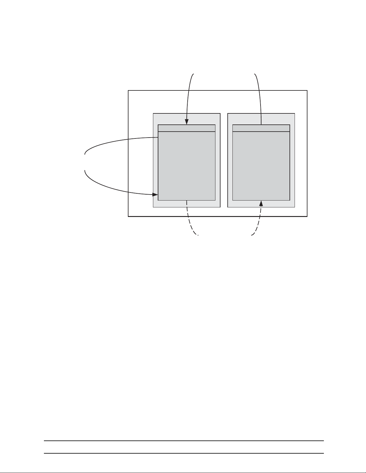
10 Configuration File Handling
VolatilePersistent
config:
¥Shipping
Configuration
Òshipping-configÓ
(read-only)
¥Startup
Configuration
Òstartup-configÓ
¥ User specific
Configuration
Òuser-configÓ
system:
¥current Running
Configuration
Òrunning-configÓ
Local Memory Regions
Store the current Running
Configuration persistently
Local(Intelligent Access Device)
Only on Startup to execute
the Startup or Shipping
Configuration
Copy Configuration Files within
the persistent Memory Region
In most cases, the interactively modified running configuration known as the running-config, which is
located in the volatile memory region system:, is copied into the persistent memory region config. This run
ning config is stored under the name startup-config and replaces the existing startup configuration.
You can copy the current running configuration into the persistent memory region config: under a userspecified name, if you want to preserve that configuration.
In addition, an already existing configuration is usually copied into the persistent memory region config: by
using a user-specified name, for conservation or later activation.
As shown in figure 16 the local memory regions are identified by their unique names, like config:, which is
located in flash memory, and system:, which is the system RAM, i.e. the volatile memory. As already mentioned, configuration files in the same memory region need a unique name. For example, it is not possible
to have two configuration files with the name running-config in the memory region config:.
As you might expect, the copy command does not move but replicates a selected source to a target configuration file in the specified memory region. Therefore the source configuration file is not lost after the copy
process. There are four predefined configuration file names for which it is optional to specify the memory
region, namely shipping-config, startup-config, minimal-config and running-config.
Figure 16 Local memory regions
-
724-746-5500 | blackbox.com
Page 65
Page 66
10 Configuration File Handling
Mode: Administrator execution
Step Command Purpose
device#copy {shipping-config | startup-config |
1
minimal-config | running-config | config: source-
name } config: target-name
Example: Backing up the startup configuration
The following example shows how to make a backup copy of the startup configuration. It is copied under
the name backup into the flash memory region config:.
device#copy startup-config config:backup
Copies the selected source configuration file sourcename as target configuration file target-name into the
local memory.
10.4.2 REPLACING THE STARTUP CONFIGURATION WITH A CONFIGURATION FROM FLASH MEMORY
It is possible to replace the startup configuration by a configuration that is already present in the flash memory. You can do so by copying it to the area of the flash memory where the startup configuration is stored.
Mode: Administrator execution
Step Command Purpose
Replaces the existing persistent startup configu-
1 device# copy config:backup startup-config
Note The configuration backup can be a previously backed up configuration or previously downloaded from
a TFTP server.
ration with the startup configuration backup
already present in flash memory.
10.4.3 COPYING CONFIGURATIONS TO AND FROM A REMOTE STORAGE LOCATION
Configuration files can be copied from local memory (persistent or volatile region) to a remote data store.
From within the OS, the remote TFTP server is represented by the memory region tftp: in combination with
the IP address of the TFTP server and the name and path of the configuration file. We will explain the
usage of the remote memory region tftp: in the following section more detailed. Another typical task is
uploading the current running configuration to the remote data store for backup purpose, or if an extensive
configuration file is to be edited on the remote host. In this case the running configuration, named running-
config, which is to be found in the volatile memory region system: is transferred to the TFTP server. On the
TFTP server the running configuration is stored to a file whose name is defined as one of the arguments of
the copy command.
724-746-5500 | blackbox.com
Page 66
Page 67
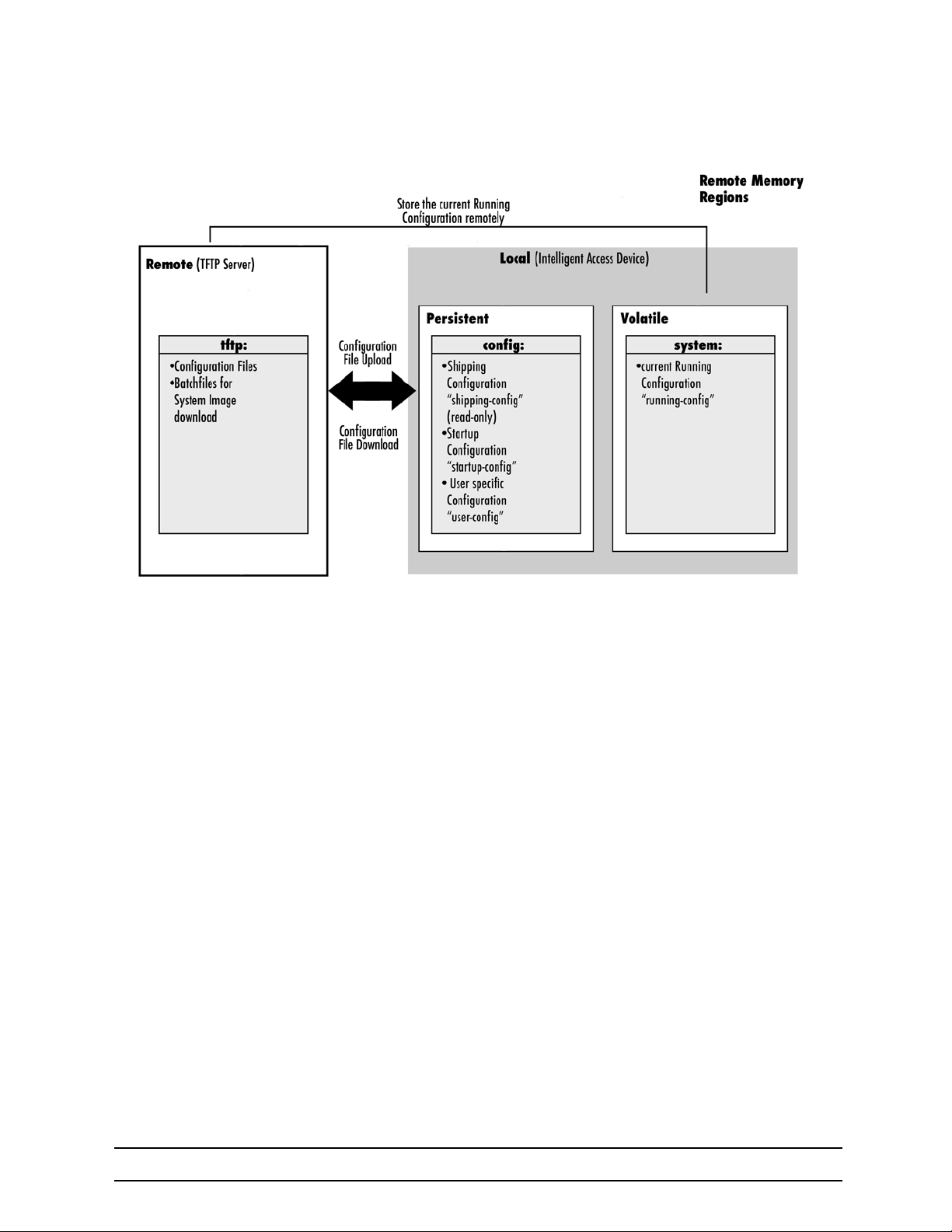
10 Configuration File Handling
Figure 17 Remote memory regions for the OS
Finally, configuration files, i.e. the startup configuration or a user-specific configuration that is stored in the
persistent memory region config: are often uploaded to the remote data store for backup, edit or cloning
purposes. The latter procedure is very helpful when you have several Black Box devices, each using a con
figuration which does not greatly differ from the others, or which is the same for all devices. During the configuration of the LB52XA-R2 according to your requirements, the running configuration of this device,
named running-config and located in the volatile memory region system:, is edited. Next, the configuration
is tested and if everything is as required, the running configuration is copied as startup configuration,
named startup-config, into the persistent memory region config: of the target device. After this, the startup
configuration is transferred to the TFTP server, where it can be distributed to other Black Box devices.
These devices therefore get clones of the starting system if the configuration does not need any modifica
tions.
10.4.4 REPLACING THE STARTUP CONFIGURATION WITH A CONFIGURATION DOWNLOADED FROM TFTP SERVER
From within the administration execution mode, you can replace the startup-configuration by downloading a
configuration from the TFTP server into the flash memory area where to store the startup configuration.
-
-
724-746-5500 | blackbox.com
Page 67
Page 68
10 Configuration File Handling
IMPORTANT
Mode: Administrator execution
Step Command Purpose
Downloads the configuration file new-startup from the
TFTP server at address ip-address replacing the existing
persistent startup configuration. Optionally you can enter
device(cfg)# copy tftp://ip-address[:port]/new-
1
startup config:startup-config
Example: Sample configuration download from the TFTP server
The following example shows how to replace the persistent startup configuration in the flash memory of a
Black Box device by overwriting it with the configuration contained in the file new-startup located on the
TFTP server at IP address 172.16.36.80.
1. Download the startup configuration with the copy command into the flash memory area where to store
the startup configuration.
device>enable
device#configure
device(cfg)#copy tftp://172.16.36.80/user/new-startup config:startup-config
Download...100%
device(cfg)#
2. Check the content of the persistent startup configuration by listing its command settings with the show
command.
device#show config:startup-config
the UDP port where the TFTP server listens. If the port is
not specified, the default port 69 is used. This progress is
visualized with a counter, counting up from 0 to 100%
according to the downloaded amount of the file size.
Should the download fail, an error message % File Trans
fer - Get failed is displayed.
-
10.4.5 DISPLAYING CONFIGURATION FILE INFORMATION
This procedure describes how to display information about configuration files
Mode: Administrator execution
Command Purpose
show config: Lists all persistent configurations
show running-config Displays the contents of the running configuration file
show startup-config Displays the contents of the star tup configuration file
show running-config current-mode Displays only the running-config of the current mode.
show running-config "<some mode>" Displays the running-config of any named mode
It is recommended that you never save a configuration in startup-con-
fig or a user-specific configuration with the cli config defaults command
because the additional list of default commands consumes significant
portions of the config: memory.
Note Application files can be very long when displayed (by using the show command). To make them easier
to read, many default commands are not displayed when executing the show running-config command.
However, the administrator may want to see the entire configuration, including these normally “hidden”
724-746-5500 | blackbox.com
Page 68
Page 69

10 Configuration File Handling
default commands. To see all commands, execute the cli config defaults command. By issuing a show
running-config command afterwards, you will see all the commands, a list which is significantly longer.
To hide these hidden commands again, issue the no cli config defaults command.
10.4.6 MODIFYING THE RUNNING CONFIGURATION AT THE CLI
The OS accepts interactive modifications on the currently running configuration via the CLI. Interactive configuring needs access to the CLI. Use the enable command to enter administrator execution mode, and
then switch to the configuration mode by typing the command configure. Once in configuration mode, you
can enter the configuration commands that are necessary to your Black Box device’s operation. When you
configure the OS by using the CLI, the shell executes the commands as you enter them.
When you log in using the CLI, all commands you enter directly modify the running configuration located in
the volatile memory region system: (or RAM) of your device. Because it is located in volatile memory, to be
made permanent, your modifications must be copied to the persistent (non-volatile) memory. In most cases
you will store it as the upcoming startup configuration in the persistent memory region config: under the
name startup-config. On the next start-up the system will initialize itself using the modified configuration.
After the startup configuration has been saved to persistent memory, you have to restart the device by
using the reload command to cause the system to initialize with the new configuration.
The execution command reload accepts with the following option:
•
forced—reloads the system without prompting for confirmation or for saving the running-configuration
(no need to type yes or no). The question whether to save the running-configuration is automatically
answered with no, the question whether to reload or not with yes.
Mode: Administrator execution
Step Command Purpose
1 device#configure Enters administrator configuration mode
2 Enter all necessary configuration commands.
3 device(cfg)#copy running-config startup-config
4 device(cfg)#reload Restarts the system
Saves the running configuration file as the upcoming startup configuration
Example: Modifying the running configuration at the CLI
The following example shows how to modify the currently running configuration via the CLI and save it as
the startup configuration.
device#configure
device(cfg)#…
device(cfg)#copy running-config startup-config
device(cfg)#reload
Press 'yes' to restart, 'no' to cancel: yes
The system is going down
10.4.7 MODIFYING THE RUNNING CONFIGURATION OFFLINE
In cases of complex configuration changes, which are easier to do offline, you may store a configuration on
a TFTP server, where you can edit and save it. Since the LB52XA-R2 is acting as a TFTP client, it initiates
all file transfer operations.
First, upload the running configuration, named running-config, from the LB52XA-R2 to the TFTP server.
You can then edit the configuration file located on the TFTP server by using any regular text editor. Once
the configuration has been edited, download it back into the device as upcoming startup configuration and
724-746-5500 | blackbox.com
Page 69
Page 70

10 Configuration File Handling
store it in the persistent memory region config: under the name startup-config. Finally, restart the LB52XAR2 by using the reload command to activate the changes.
Mode: Administrator execution
Step Command Purpose
Uploads the current running configuration as file current-config to
the TFTP server at address device-ip-address. Optionally you
device#copy running-config tftp://device-
1
ip-address[:port]/current-config
2
device#copy tftp://device-ip-address/cur-
3
rent-config config: startup-config
4 device#reload Restarts the system
can enter the UDP port where the TFTP server listens. If the port
is not specified, the default port 69 is used. This progress is visu
alized with a counter, counting up from 0 to 100% according to
the downloaded amount of the file size. If the upload should fail
an error message “% File Transfer - Put failed” is displayed.
Offline editing of the configuration file current-config on the TFTP
server using any regular text editor.
Downloads the modified configuration file current-config from the
TFTP server at address device-ip-address into the persistent
memory region config: by using the name startup-config. This
progress is visualized with a counter, counting up from 0 to 100%
according to the downloaded amount of the file size. Should the
download fail, an error message “% File Transfer - Get failed” is
displayed.
-
Example: Modifying the running configuration offline
The following example shows how to upload the running configuration from the LB52XA-R2 to the file cur-
rent-config on a TFTP server at IP address 172.16.36.80. The uploaded configuration file is written into the
root directory specified by the TFTP server settings, and overwrites any existing file with the same name.
Read your TFTP server manual to get a thorough understanding of its behavior. After this, the configuration
file is available for offline editing on the TFTP server. Once the configuration file current-config has been
modified, it is downloaded from the TFTP server, at IP address 172.16.36.80, into the persistent memory
region config: using the name startup-config. It will become active after a reload.
device#copy running-config tftp://172.16.36.80/user/current-config
Upload...100%
At this point in time, the offline editing of the configuration file current-config on the TFTP server takes
place.
device#copy tftp://172.16.36.80/user/ current-config config:startup-config
Download...100%
device#reload
Press 'yes' to restart, 'no' to cancel: yes
The system is going down
724-746-5500 | blackbox.com
Page 70
Page 71

10 Configuration File Handling
10.4.8 DELETING A SPECIFIED CONFIGURATION
This procedure describes how to delete configuration files from the LB52XA-R2 flash memory region config:.
Mode: Administrator execution
Step Command Purpose
1 device#show config: Lists the loaded configurations
2 device#erase config:name Deletes the configuration name from the flash memory.
Example: Deleting a specified configuration
The following example shows how to delete a specific configuration from among a set of three available
configurations in Flash memory. The configuration named minimal is to be deleted, since it is no longer
used.
1. Use the command show config: to list all available configurations.
device#show config:
Persistent configurations:
backup
minimal
startup-config
shipping-config
2. Delete the configuration named minimal explicitly.
device#erase config:minimal
3. Enter again the command show config: to check if the selected configuration was deleted successfully
from the set of available configurations.
device#show config:
Persistent configurations:
backup
startup-config
shipping-config
724-746-5500 | blackbox.com
Page 71
Page 72

11 BASIC SYSTEM MANAGEMENT
Chapter contents
11. Basic System Management ........................................................................................................ 72
11.1 Introduction................................................................................................................................ 73
11.2 Basic System Management Configuration Task List ..................................................................73
11.2.1 Managing Feature License Keys ...............................................................................................73
11.2.2 Setting System Information ........................................................................................................ 74
11.2.3 Setting the System Banner ........................................................................................................ 75
11.2.4 Setting Time and Date ............................................................................................................... 76
11.2.5 Configuring Daylight Savings Time Rules .................................................................................. 76
11.2.6 Display Clock Information .......................................................................................................... 77
11.2.7 Display Time Since Last Restart ................................................................................................77
11.2.8 Configuring the Web Server ....................................................................................................... 77
11.2.9 Restarting the System ................................................................................................................ 78
11.2.10 Displaying the System Logs ....................................................................................................... 78
11.2.11 Displaying Reports ..................................................................................................................... 79
11.2.12 Configuring the blink interval ......................................................................................................79
11.2.13 Configuring the Syslog Client ..................................................................................................... 79
724-746-5500 | blackbox.com
Page 72
Page 73

11 Basic System Management
11.1 INTRODUCTION
This chapter describes parameters that report basic system information to the operator or administrator,
and their configuration. The following are basic parameters that can be established when setting up a new
system:
•
Defining the system's hostname
•
Setting the location of the system
•
Providing reference contact information
•
Setting the clock
Additionally, the following tasks are described in this chapter:
•
Setting the system banner
•
Enabling the embedded web server
11.2 BASIC SYSTEM MANAGEMENT CONFIGURATION TASK LIST
All tasks in the following sections are optional, though some such as setting time and calendar services
and system information are highly recommended.
To configure basic system parameters, perform the tasks described in the following sections.
•
Managing feature license keys (see page 73)
•
Setting system information (see page 74 )
•
Setting the system banner (see page 75)
•
Setting time and date (see page 76)
•
Displaying clock information (see page 77)
•
Displaying time since last restart (see page 77)
•
Configuring and starting the web server (see page 77)
•
Restarting the system (see page 78)
•
Displaying the system event log (see page 78)
•
Identifying a unit by flashing all LED’s (see page 79)
11.2.1 MANAGING FEATURE LICENSE KEYS
Several features of the firmware require a system specific license key to be installed to enable the feature.
This section describes how to install the feature license keys on your equipment.
Mode: Configure
Step Command Purpose
1 device(cfg)#install license license-key Install the license key
2 Repeat step 1 for any additional license keys
724-746-5500 | blackbox.com
Page 73
Page 74

11 Basic System Management
Example: Installing license keys from the console
The following example shows the command used to install license keys manually on the console.
device(cfg)#install license 10011002R1Ws63yKV5v28eVmhDsVGj/JwKqIdpC4Wr1BHaN-
tenXUYF/2gNLoihifacaTPLKcV+uQDG8LJis6EdW6uNk/GxVObDEwPFJ5bTV3bIIfUZ1eUe+8c5OpCCd7PSAe83Ty2c/
CnZPSlEjIrVlJrr8VhOr1DYxkEV9evBp+tSY+y9sCeXhDWt5Xq15SAPlznTLQmym7fDa
kvm+zltzswX/KX13sdkR0ub9IX4Sjn6YrvkyrJ2dCGivTTB3iOBmRjV1u
After installing license keys, you can check if the license keys have been added successfully to your system
using the following command.
Mode: Configure
Step Command Purpose
1 device(cfg)#show licenses Display all installed licenses
Example: Displaying installed licenses
The following example shows the command used to display all installed licenses on a system and a sample
of its output.
device(cfg)#show licenses
VPN [vpn]
License serial number: 14343534
Status: Active
device(cfg)#
-
11.2.2 SETTING SYSTEM INFORMATION
The system information includes the following parameters:
•
Contact
•
Hostname
•
Location
•
Provider
•
Subscriber
•
Supplier
By default there is no information specified for any of the above parameters.
System contact information tells the user how to contact the information service, e.g. the help line of the
service provider. The contact information may be any alphanumeric string, including spaces, that is no lon
ger than one line. This entry corresponds to the MIB II system sysContact object.
The system name, also called the hostname, is used to uniquely identify the LB52XA-R2 in your network.
The selected name should follow the rules for ARPANET hostnames. Names must start with a letter, end
with a letter or digit, and have as interior characters only letters, digits, and hyphens. Names must be 63
characters or fewer. For more information, refer to RFC 1035. This entry corresponds to the MIB II system
sysName object. After setting the hostname of the LB52XA-R2 the CLI prompt will be replaced with the
chosen name.
-
724-746-5500 | blackbox.com
Page 74
Page 75

11 Basic System Management
Assigning explanatory location information to describe the system physical location of your device (e.g.
server room, wiring closet, 3rd floor, etc.) is very supportive. This entry corresponds to the MIB II system
sysLocation object.
The system provider information is used to identify the provider contact for the LB52XA-R2, together with
information on how to contact this provider. The provider is a company making services available to sub
scribers. The provider information may be any alphanumeric string, including spaces, that is no longer than
one line. This entry corresponds to the Black Box enterprise-specific MIB provider object.
The system subscriber information is used to get in touch with subscriber for the LB52XA-R2, together with
information on how to contact this subscriber. The subscriber is a company or person using one or more
services from a provider. The subscriber information may be any alphanumeric string, including spaces,
that is no longer than one line. This entry corresponds to the Black Box enterprise-specific MIB subscriber
object.
The system supplier information is used to get in touch with the supplier for the LB52XA-R2, together with
information on how to contact this supplier. The supplier is a company delivering Black Box devices to a
provider. The supplier information may be any alphanumeric string, including spaces, that is no longer than
one line. This entry corresponds to the Black Box enterprise-specific MIB supplier object.
Mode: Configure
Step Command Purpose
1 device(cfg)#system contact information Sets the contact information to information
2 device(cfg)#system hostname information Sets the hostname to information
3 device(cfg)#system location information Sets the location information to information
4 device(cfg)#system provider information Sets the provider information to information
5 device(cfg)#system subscriber information Sets the subscriber information to information
6 device(cfg)#system supplier information Sets the supplier information to information
-
Note If the system information must have more than one word, enclose it in double quotes.
Example: Setting system information
The following example shows the commands used to configure the contact information for the LB52XA-R2,
if you start from the operator execution mode.
device(cfg)#system contact "Bill Anybody, Phone 818 700 1504"
device(cfg)#system hostname device
device(cfg)#system location “Wiring Closet, 3rd Floor”
device(cfg)#system provider “Best Internet Services, [email protected], Phone 818 700
2340”
device(cfg)# system subscriber “Mechanical Tools Inc., [email protected], Phone
818 700 1402”
device(cfg)# system supplier “WhiteBox Networks Inc., [email protected], Phone
818 700 1212”
11.2.3 SETTING THE SYSTEM BANNER
The system banner is displayed on all systems that connect to your LB52XA-R2 via Telnet, SSH, or a serial
connection. It appears at login and is useful for sending messages that affect administrators and operators,
such as scheduled maintenance or system shutdowns. By default no banner is present on login.
To create a system banner use the banner command followed by the message you want displayed. If the
banner message has to be formed out of more than one word the information is enclosed by double
724-746-5500 | blackbox.com
Page 75
Page 76

11 Basic System Management
quotes. Adding the escape sequence “\n” to the string forming the banner creates a new line on the connected terminal screen. Use the no banner command to delete the message.
Mechanical Tools Inc.
[email protected]
Phone 818 700 1402
login:
Mode: Configure
Step Command Purpose
1 device(cfg)#banner message Sets the message for the system banner to message
Example: Setting the system banner
The following example shows how to set a message for the system banner for the LB52XA-R2, if you start
from the configuration mode.
device(cfg)#banner \n#\n# The password of all operators has changed\n# please con-
tact the administrator\n#"
11.2.4 SETTING TIME AND DATE
All Black Box devices provide time-of-day and date services. These services allow the products to accurately keep track of the current time and date. The system clock specifies year, month, day, hour, minutes,
and optionally seconds. The time is in 24-hour format yyyy-mm-ddThh:mm:ss and is retained after a
reload.
Mode: Configure
Step Command Purpose
1 device(cfg)#clock set yyyy-mm-ddThh:mm:ss Sets the system clock to yyyy-mm-ddThh:mm:ss
Example: Setting time and date
The following example shows the commands used to set the system clock of your device to August 6, 2001
at 16:55:57, if you start from the operator execution mode.
device(cfg)#clock set 2001-08-06T16:55:57
11.2.5 CONFIGURING DAYLIGHT SAVINGS TIME RULES
The OS allows configuring daylight saving time rules, which affect the local clock offset without changing
the configuration. After booting up and loading the configuration, the daylight saving rules are checked and
applied automatically. The rules consist of a default-offset and one or multiple dst-rules. The offset of a dstrule is active if the local clock is between the specified start and stop time of the rule. If the local clock is
outside the specified start and stop time of all specified rules, then the default-offset is active.
Mode: Configure
Step Command Purpose
device(cfg)#clock local default-offset
1
(+hh:mm | -hh:mm)
Configures the offset of your time zone from GMT.
This offset is used if no other dst rule is currently
active. Default: +00:00
724-746-5500 | blackbox.com
Page 76
Page 77
11 Basic System Management
11.2.6 DISPLAY CLOCK INFORMATION
This procedure describes how to display the current date and time
Mode: Both in operator and administrator execution
Step Command Purpose
1 device>show clock Display the local time.
Example: Display clock information
The following example shows the commands used to display the time and date settings of your device in
local time, if you start from the operator execution mode.
device>show clock
2001-08-06T16:55:57
11.2.7 DISPLAY TIME SINCE LAST RESTART
This procedure describes how to display the time since last restart
Mode: Operator execution
Step Command Purpose
1 device>show uptime Display the time since last restart.
Example:
The following example shows how to display the uptime of your device, if you start from the configuration
mode.
device>show uptime
The system is up for 54 days, 23 hours, 44 minutes, 18 seconds
11.2.8 CONFIGURING THE WEB SERVER
The embedded web server has two parameters that are configurable.
Note Changing the language parameter does not affect the language of the web configuration pages.
Mode: Configure
Step Command Purpose
device(cfg)#webserver [http | https]
1
port port-number
Start the http or https server, and set the listening port number. The
default port number for the http web server is 80, and the default port
number for the https web server is 443.
Example: Configuring and starting the Web server
The following example shows how to set the web server language and the listening port of your device, if
you start from the configuration mode.
device(cfg)#webserver http port 80
device(cfg)#webserver http
724-746-5500 | blackbox.com
Page 77
Page 78
11 Basic System Management
IMPORTANT
11.2.9 RESTARTING THE SYSTEM
In case the LB52XA-R2 has to be restarted, the reload command must be used. The reload command
includes a two-dialog, where the user is allowed to store any unsaved configuration data and finally con
firms the system restart.
Restarting the system interrupts running data transfers and all voice
calls.
The execution command reload has been enhanced with the following option:
•
forced—reloads the system without prompting for confirmation or for saving the running-configuration
(no need to type yes or no). The question whether to save the running-configuration is automatically
answered with no, the question whether to reload or not with yes.
Mode: Administrator execution
Step Command Purpose
1 device#reload Restarts the system
-
Example: Restarting the system
The following example shows how to restart the currently running system, if you start from the administrator
execution mode.
device#reload
System configuration has been changed.
Press 'yes' to restart, 'no' to cancel: yes
The system is going down
11.2.10 DISPLAYING THE SYSTEM LOGS
The system logs contain warnings and information from the system components of the OS. In case of problems it is often useful to check the event or the supervisor logs for information about malfunctioning system
components. The event log stores general events such as flash full, DSP failed etc., comparable with the
event log on Windows NT. The supervisor log stores information from the system supervisor such as mem
ory full, task failed etc.
System resets may have a number of reasons, the most prominent being a manual reset issued on the Telnet/console (‘reload’). Other reset reasons include power off failures and system failures. In order to pinpoint the problem, the reset log contains the reset cause.
Mode: Administrator execution
Step Command Purpose
1 device#show log event Show event log.
2 device#show log supervisor
3 device#show log reset Output a list of reset reasons (with date and time).
4 device#show log boot Displays the console and log messages captured during startup of the unit.
Show log of the system supervisor. Used For example, after an unexpectedly reboot.
-
724-746-5500 | blackbox.com
Page 78
Page 79
11 Basic System Management
11.2.11 DISPLAYING REPORTS
The show reports command is used to dump combined system information. The show reports command
sequentially executes the following log commands:
show version
show clock
show uptime
show log reset
show log boot
show log event
show log supervisor
show factory-config
show startup-config
show running-config
Mode: Administrator execution
Step Command Purpose
1 device#show reports Dumps the combined system information.
11.2.12 CONFIGURING THE BLINK INTERVAL
When there are many embedded OS devices in the same location, use this command to flash all the LED’s
on a specific unit for a specified period of time. This makes identification of the physical unit very easy.
Step Command Purpose
1 device #blink <seconds>
Enter an integer for the period of time you want the LED’s
to flash on the physical unit.
11.2.13 CONFIGURING THE SYSLOG CLIENT
Syslog is a protocol for sending event notification messages across IP networks to message collectors
(Syslog server). It uses transport protocol UDP on port 514. A syslog-message exits on the three main part
Priority, Header and Message whereas the header is split into Facility and Severity and the header into
Timestamp and Hostname. The whole syslog-message (Priority, Header and Message) contains only print
able characters and the maximum length is 1024 bytes.
Mode: Configure
Step Command Purpose
1 device(cfg)#syslog-client Enters syslog client configuration mode.
-
724-746-5500 | blackbox.com
Page 79
Page 80
11 Basic System Management
Mode: Syslog Client
Step Command Purpose
Creates a new remote destination and enters its configura-
device(syslog-client)#[no] remote { <ipv4 host> |
1
<ipv6 host> } [ tcp | udp ] [ <port> ]
Mode: Remote
Step Command Purpose
device(syslog-client)(remote)#[no] facility <ser-
1
vice name> <severity>
tion mode. The 'no' form of the command removes an existing remote destination. The protocol type and port are
optional. If not included, the default UDP port 512 will be
used.
Creates a new log expression for a remote destination. It
exists on a facility that determines from which source mes
sages must be accepted and a severity that defines up to
which level the messages of the given facility must be sent.
The 'no' form of the command disables sending of mes
sages from the given facility.
-
-
724-746-5500 | blackbox.com
Page 80
Page 81

12 WIZARD INTERFACE
Chapter contents
12. Wizard Interface.......................................................................................................................... 81
12.1 Introduction................................................................................................................................ 82
12.2 Browser Notes ............................................................................................................................82
12.3 Connect with Web GUI ...............................................................................................................82
12.3.1 Management IP Setup ............................................................................................................... 84
12.3.2 Line Setup .................................................................................................................................. 84
724-746-5500 | blackbox.com
Page 81
Page 82
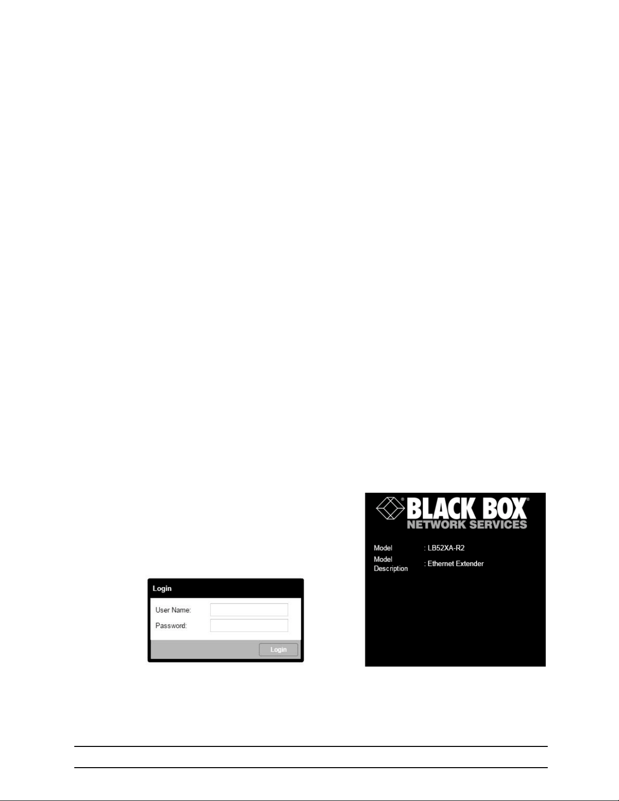
12 Wizard Interface
12.1 INTRODUCTION
The Embedded Operating System (OS) Devices are designed with an intuitive Command Line Management Interface. They also have a limited or basic Web Management Interface for easy firmware support
and access to the XML Wizard function. This Chapter will give you a quick walk through how to use the
Wizard that has been loaded on to the device from the Black Box Factory. These Wizards can be both
imported and exported and modified easily by using your favorite color code or text editor. The wizard is a
simple XML script that loads your new graphical changed into the startup configuration file saves and
reboots. This means that the Wizard changes don’t affect any running configurations. These changes are
simply static and do not affect your running configuration until the unit is rebooted.
12.2 BROWSER NOTES
Recommended that you use the most recent browser with the latest security updates. You may find the
XML scripting does not work well with older outdated browsers. We have tests with Chrome 39, MS IE 9,
and Firefox 33. If you are experiencing page display problems please update your browser with the latest
update. Once you have updated your favorite browser you can access the device with the newly configured
IP address or the Factory Default IP: 192.168.200.10/24
12.3 CONNECT WITH WEB GUI
1. Connect the Ethernet cable.
2. Connect the power supply.
3. Connect via web browser to the default address 192.168.200.10 OR connect to 192.168.200.11 for 2
pack local units.
4. Login with the default username admin without a password.
Once the network connection is established, you will be able to reach the LB52XA-R2 Web GUI. Login to
the Web GUI using the following credentials in
•
Username: admin
•
Password: [blank]
figure 18.
724-746-5500 | blackbox.com
Figure 18 Login
Page 82
Page 83
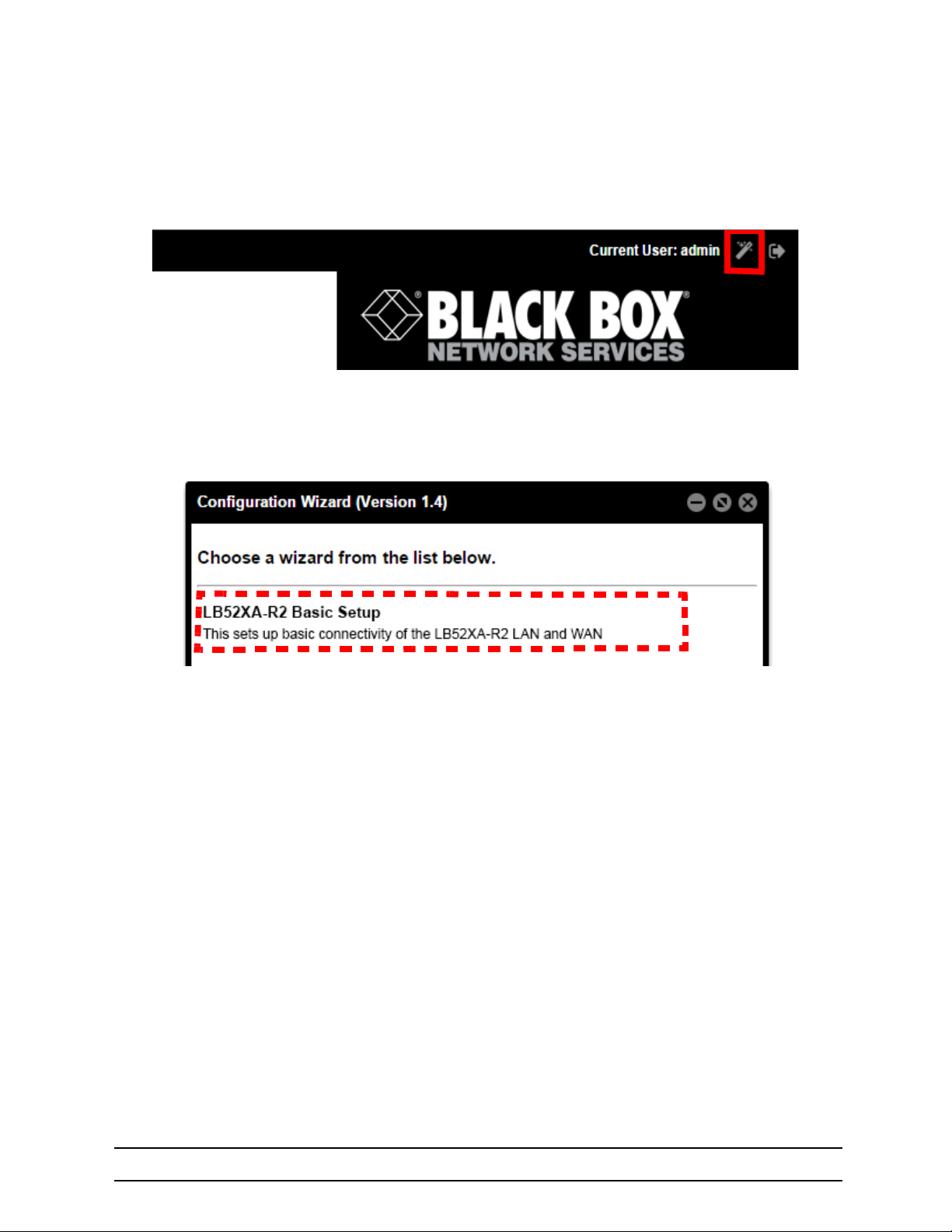
12 Wizard Interface
The LB52XA-R2 includes a Wizard within the GUI. The icon to the wizard is in the top right corner of your
browser as it displays in
Once the wizard icon is selected, you will have the options of supported set ups as shown in figure 20. Click
on LB52XA-R2 Basic Setup.
figure 19.
Figure 19 Wizard Homepage.
Figure 20 Choose Wizard
Clicking on the LB52XA-R2 Basic Setup will bring up the most common configurations used on the Ethernet Extenders.
Figure 21 on page 84 depicts options to configure through the Basic Setup Wizard.
724-746-5500 | blackbox.com
Page 83
Page 84
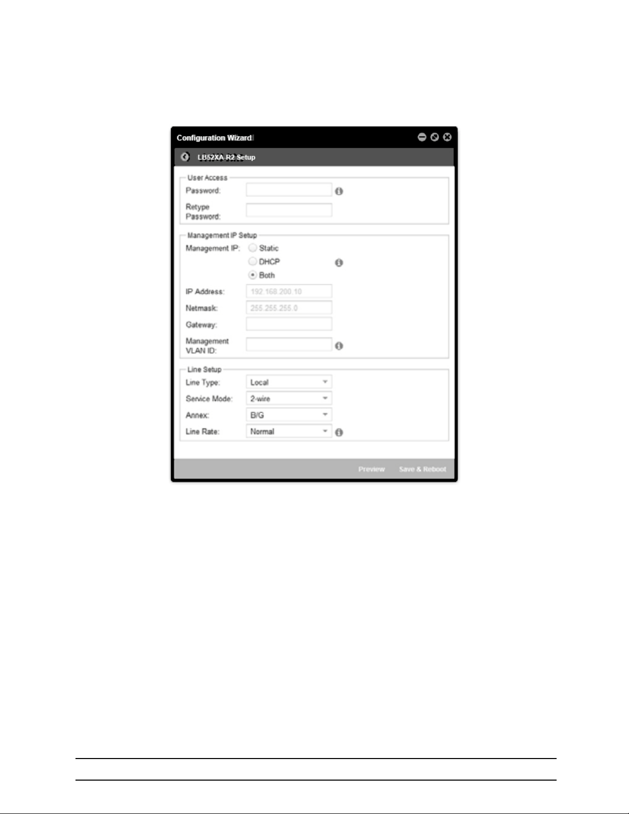
12 Wizard Interface
Figure 21 Basic Setup
User Access: (optional configuration) Users may change the password for the admin user.
12.3.1 MANAGEMENT IP SETUP
•
Static: create your own IP address, netmask and gateway (optional: the gateway is required for
remote management).
•
DHCP: The LB52XA-R2 management port will accept an IP address from a DHCP server.
•
Both: This choice will assign two IP addresses (one static and one DHCP to the management port.)
•
Management VLAN ID: (optional) define a VLAN ID for management traffic.
12.3.2 LINE SETUP
This is where you can manually set your line port options.
Note The Ethernet Extenders by default are set to plug-and-play operation
•
Line Type (Local or Remote): This will set the Ethernet Extender as Local or Remote. Local is typi-
cally used at the network, Remote is typically used at the remote device or remote network. Your
724-746-5500 | blackbox.com
Page 84
Page 85
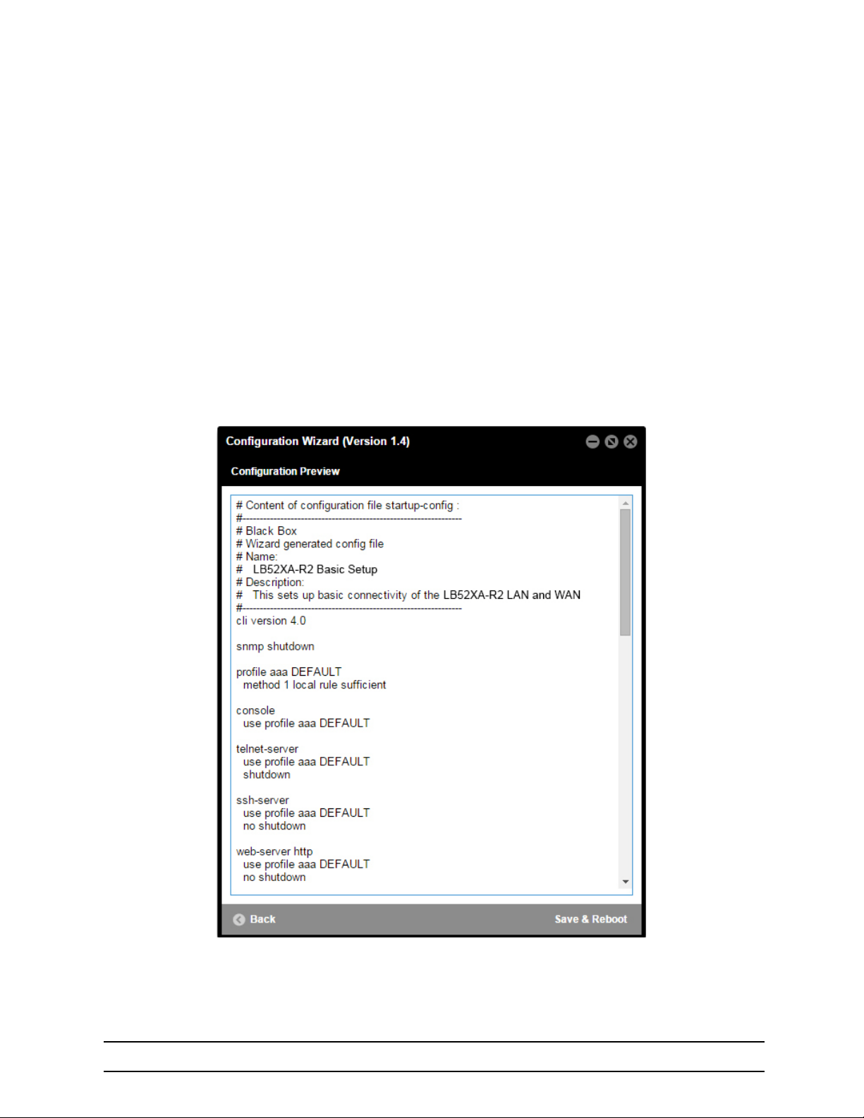
12 Wizard Interface
LB52XA-R2 when received in a 2-pack is already configured one LB52XA-R2 as Local and one
LB52XA-R2 as Remote.
•
Service Mode: Configures the number of pairs (wires) you want to use. The LB52XA-R2 will default to
the maximum number of wires available on your version of the LB522A-R2 (2-wire); LB524A-R2 (4wire); LB528A-R2 (8-wire).
•
Annex: Please consult support before changing this setting.
•
Line Rate Configuration: This will increase the potential line rate of the LB52XA-R2. Your LB52XA-
R2 is defaulted to automatically select the optimal rate based on the distance (adaptive).
Note There are two mates: Normal (TCPAM16|32) and Extended (TCPAM64|128). Selecting the Extended
mode will double the bandwidth, but will reduce the reach (distance) in half. Default is normal.
On the bottom right corner of the LB52XA-R2 Basic Configuration wizard page to preview configurations
and reboot.
Figure 22 depicts what you can expect to see if you click on the preview tab.
Figure 22 Configure Preview Option
724-746-5500 | blackbox.com
Page 85
Page 86
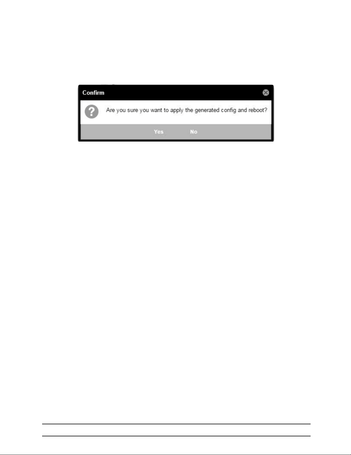
12 Wizard Interface
When the user chooses the save and reboot option, a prompt will ask you to confirm. If the configuration is
correct, select “Yes” as shown in
Typically the time to reboot and reestablish a line link and pass traffic once again will be under 2 minutes.
figure 23.
Figure 23 Confirmation
724-746-5500 | blackbox.com
Page 86
Page 87

13 IP ROUTING
Chapter contents
13. IP Routing ...................................................................................................................................87
13.1 Introduction................................................................................................................................ 88
13.2 Basic Routing.............................................................................................................................. 88
13.3 Static Routes............................................................................................................................... 88
13.4 Configuring static routes ............................................................................................................. 88
13.5 System Routes............................................................................................................................ 89
13.6 Dynamic Routes.......................................................................................................................... 90
13.7 Show Routes............................................................................................................................... 90
13.8 Basic Static Routing Example..................................................................................................... 90
724-746-5500 | blackbox.com
Page 87
Page 88

13 IP Routing
13.1 INTRODUCTION
The OS IP Routing facility consists of the two major functionalities: Basic Routing and Policy Routing.
13.2 BASIC ROUTING
Under Basic Routing is to be understood the destination IP address based next-hop determination. The
next-hop or gateway selection is done by matching a set of routing rules entered by the user (static-route),
received through a routing-protocol (dynamic-route) or added by the system (system-route). Routing entries
which specify a gateway as next-hop are also called gateway-routes. Networks that are directly reachable
through a device’s network-port are specified through interface-routes. Instead of a gateway they specify an
outgoing interface.
In the context ip configuration mode exists a system created routing-table called DEFAULT. This table contains all Basic Routing information and cannot be deleted by the user. Actually it is possible to created additional routing-tables with a user defined name but such user-created tables are part of the Policy Routing
and do not have any use in Basic Routing.
All Basic Routing features are available for IPv4 as well as for IPv6.
13.3 STATIC ROUTES
These are user managed gateway and interface routes and are getting exported in the running-config. In
the output of the show route command they are flagged with an “R”. Another flag “U” indicates if the route is
up or not. A static gateway-route is becoming active (up) if the gateway is reachable. For this we need the
following conditions:
•
At least one IP address in the gateway’s network has to be configured.
•
The IP interface which owns the IP address has to be bound from a network-port.
•
The network-port’s link state has to be up.
A static interface-route is becoming active (up) if:
•
The specified outgoing interface is bound from a network-port.
•
The specified outgoing interface has at least one IP address configured.
•
The network-port’s link state has to be up.
13.4 CONFIGURING STATIC ROUTES
A route is clearly identified by its destination address/mask combination and the metric. That means it is
allowed to configure several time the same destination, using the same or different gateways, but with a dif
ferent metric value. The metric in a static route has the meaning of a priority where lower value means
higher priority.
Static route differentiation by metric is useful if a destination network is reachable through different gateways. Usually gateways are located in the same network as the device itself. If the link to the gateway with
lowest metric is going down, this static-route is becoming unavailable. In that case the device’s router will
select the route to the destination with the next higher metric and another gateway is going to be used.
-
724-746-5500 | blackbox.com
Page 88
Page 89
13 IP Routing
Mode: Administrator execution
Step Command Purpose
1 [device](cfg)#context ip [ROUTER ]
2 [device](ctx-ip)[ROUTER]#routing-table [ DEFAULT ]
[device][ROUTER.DEFAULT]#route { <network>/<mask-size> | <network><mask> |default | default-v6 } { gateway <gw-address> | interface <if-name> } [ metric <metric> ]
3
OR
[device][ROUTER.DEFAULT]#no route <network>/<mask-size> [
metric <metric> ]
Syntax:
Parameter Explanation
network
mask-size Number of mask-bits defining the destination network.
mask
default
default-v6
gw-address
interface The name of the outgoing interface to be used for reaching the destination network.
metric
The destination network address in the dot-format a.b.c.d for IPv4 and in the colon-format a:b:c::x for IPv6.
The destination network mask in the dot-format a.b.c.d for IPv4 and in the colon-format
a:b:c::x for IPv6.
Short form for defining a default IPv4 route.
It configures network/mask-size with 0.0.0.0/0.
Short form for defining a default IPv6 route.
It configures network/mask-size with ::/0.
The address of the next-hop router that can access the destination network. In the dotformat a.b.c.d for IPv4 and in the colon-format a:b:c::x for IPv6.
Metric value of the route.
Default: 0
Enters the context IP ROUTER configuration mode.
Enters the routing-table DEFAULT configuration mode.
Adds a static route.
Removes a static route.
Note To configure a default static IP route, use 0.0.0.0 for the network number and mask (or ::/0 for a default
IPv6 route). A valid next-hop address or interface is required.
13.5 SYSTEM ROUTES
For each assigned IP address the system automatically creates route entries for the belonging network into
the DEFAULT routing-table. That means, all directly available networks are known by the system and don’t
have to be configured. The system-routes are of type interface-route means, only the outgoing interface is
specified and do not have the gateway parameter. In the output of the show route command they are
flagged with an “S”.
724-746-5500 | blackbox.com
Page 89
Page 90

13 IP Routing
13.6 DYNAMIC ROUTES
This kind of routes is assigned to the system either by a routing-protocol (RIP, BGP) or through a device
configuration protocol (DHCP, PPP). In the output of the show route command they are flagged with a D. A
dynamic-route is active under the same condition as a static-route.
13.7 SHOW ROUTES
Execution of show running-config command only displays the static-routes which have been added to the
system. Neither dynamic-routes nor system-routes are shown there. To get an overview of all routes actu
ally known by the system the show route command has to be executed.
Mode: Operator execution
Step Command Purpose
1 [device]#show route [ <details> ]
Output:
Routing Tables
===============================================
Flags: C - dhCp, D - Dynamic, G - use Gateway, H - target is a host
R - useR, U - route is Up, S - System
Routing Table DEFAULT, ID = 254
Destination Gateway Flags Metric Interface Source
172.16.32.0/19 SU 0 WAN 172.16.45.7
30.30.30.0/24 172.16.45.4 RU 0
172.16.32.0/19 SU 0 WAN 172.16.60.7
0.0.0.0/0 172.16.32.1 CDGU 0 eth0
Displays route information
Default: 0
-
13.8 BASIC STATIC ROUTING EXAMPLE
The picture below shows an Internetwork consisting of three routers, an LB52XA-R2 in the middle, and the
four autonomous networks, with network addresses 10.1.5.0/16, 172.16.40.0/24, 172.17.100.0/24 and
10.2.5.0/16. The LB52XA-R2 shall be configured for the following IP routing scenario:
All packets for the Workstation with IP address 10.1.5.10 shall be forwarded to the next-hop router Calvin.
All packets for network 10.2.5.0/16 shall be forwarded to the next-hop router Hobbes.
724-746-5500 | blackbox.com
Page 90
Page 91
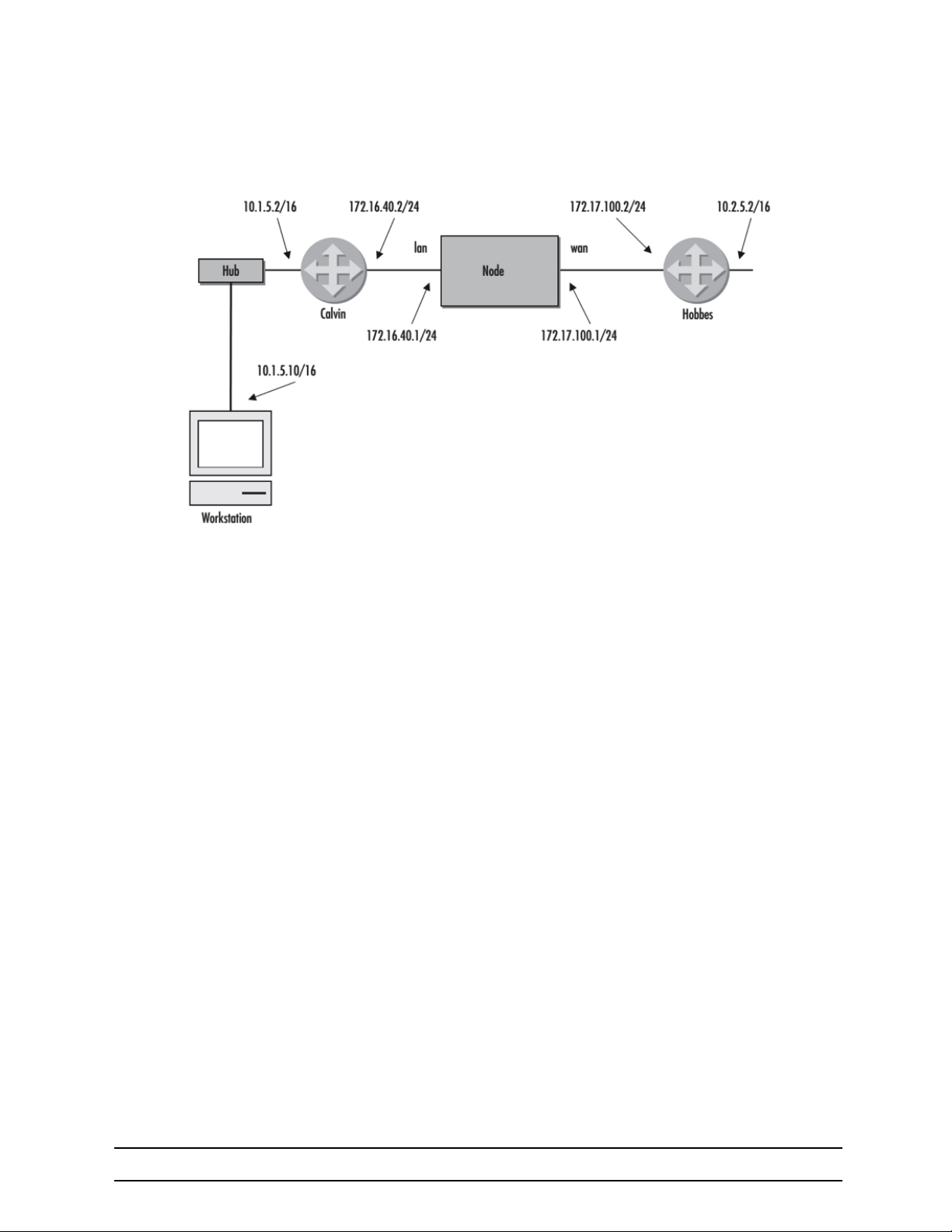
Figure 24 Static route example
13 IP Routing
Example Configuration:
context ip ROUTER
routing-table DEFAULT
route 10.1.5.10/32 gateway 172.16.40.2 metric 0
route 10.2.0.0/16 gateway 172.17.100.2 metric 0
Show Route Output:
Routing Tables
===============================================
Flags: C - dhCp, D - Dynamic, G - use Gateway, H - target is a host
R - useR, U - route is Up, S - System
Routing Table DEFAULT, ID = 254
Destination Gateway Flags Metric Interface Source
172.16.40.0/24 SU 0 LAN 172.16.40.1
172.17.100.0/24 SU 0 WAN 172.17.100.1
10.1.5.10/32 172.16.40.2 RU 0
10.2.0.0/16 172.17.100.2 RU 0
724-746-5500 | blackbox.com
Page 91
Page 92

14 SNMP CONFIGURATION
Chapter contents
14. SNMP Configuration ................................................................................................................... 92
14.1 Introduction................................................................................................................................ 93
14.2 Simple Network Management Protocol (SNMP)......................................................................... 93
14.2.1 SNMP Basic Components .........................................................................................................93
14.2.2 SNMP Basic Commands ........................................................................................................... 93
14.2.3 SNMP Management Information Base (MIB) ............................................................................. 94
14.2.4 Network Management Framework ............................................................................................. 94
14.3 Identification of an LB52XA-R2 via SNMP .................................................................................. 94
14.4 SNMP Tools................................................................................................................................ 95
14.5 SNMP Configuration Task List.................................................................................................... 95
14.6 Setting Basic System Information ...............................................................................................95
14.7 Setting Access Community Information ...................................................................................... 97
14.8 Setting Allowed Host Information................................................................................................ 98
14.9 Specifying the Default SNMP Trap Target.................................................................................. 98
14.10 Displaying SNMP Related Information........................................................................................99
14.11 Using the ManageEngine SNMP Utilities.................................................................................... 99
14.11.1 Using the MibBrowser .............................................................................................................. 100
14.11.2 Using the TrapViewer .............................................................................................................. 101
14.12 Standard SNMP Version 1 Traps..............................................................................................103
14.13 SNMP Interface Traps .............................................................................................................. 104
724-746-5500 | blackbox.com
Page 92
Page 93

14 SNMP Configuration
14.1 INTRODUCTION
This chapter provides overview information about Simple Network Management Protocol (SNMP) and
describes the tasks used to configure those of its features supported.
This chapter includes the following sections:
•
Simple Network Management Protocol (SNMP)
•
SNMP tools (see page 95)
•
SNMP configuration task list (see page 95)
•
Using the ManageEngine SNMP utilities (see page 99)
•
Standard SNMP version 1 traps (see page 103)
14.2 SIMPLE NETWORK MANAGEMENT PROTOCOL (SNMP)
The Simple Network Management Protocol (SNMP) is an application-layer protocol that facilitates the
exchange of management information between network devices. It is part of the Transmission Control Pro
tocol/Internet Protocol (TCP/IP) suite. SNMP enables network administrators to manage network performance, find and solve network problems, and plan for network growth.
14.2.1 SNMP BASIC COMPONENTS
An SNMP managed network consists of three key components: managed devices, agents, and networkmanagement systems (NMSs).
-
A managed device is a network SN that contains an SNMP agent and resides on a managed network.
Managed devices collect and store management information and make this information available to NMSs
using SNMP. Managed devices, sometimes called network elements, can be routers and access servers,
switches and bridges, hubs, computer hosts, or printers.
An agent is a network-management software module that resides in a managed device. An agent has local
knowledge of management information and translates that information into a form compatible with SNMP.
An NMS executes applications that monitor and control managed devices. NMSs provide the bulk of the
processing and memory resources required for network management. One or more NMSs must exist on
any managed network.
14.2.2 SNMP BASIC COMMANDS
Managed devices are monitored and controlled using four basic SNMP commands: read, write, trap, and
traversal operations.
•
The read command is used by an NMS to monitor managed devices. The NMS examines different
variables that are maintained by managed devices.
•
The write command is used by an NMS to control managed devices. The NMS changes the values of
variables stored within managed devices.
•
The trap command is used by managed devices to asynchronously report events to the NMS. When
certain types of events occur, a managed device sends a trap to the NMS.
•
Traversal operations are used by the NMS to determine which variables a managed device supports
and to sequentially gather information in variable tables, such as a routing table.
724-746-5500 | blackbox.com
Page 93
Page 94

14 SNMP Configuration
IMPORTANT
14.2.3 SNMP MANAGEMENT INFORMATION BASE (MIB)
A Management Information Base (MIB) is a collection of information that is organized hierarchically. MIBs
are accessed using a network-management protocol such as SNMP. They are comprised of managed
objects and are identified by object identifiers.
Managed objects are accessed via a virtual information store, termed the Management Information Base
or MIB. Objects in the MIB are defined using the subset of abstract syntax notation one (ASN.1) defined in
the SMI. In particular, an object identifier, an administratively assigned name, names each object type. The
object type together with an object instance serves to uniquely identify a specific instantiation of the object.
For human convenience, a textual string, termed the descriptor, to refer to the object type, is often used.
An object identifier (OID) world-wide identifies a managed object in the MIB hierarchy. The MIB hierarchy
can be depicted as a tree with a nameless root, the levels of which are assigned by different organizations.
14.2.4 NETWORK MANAGEMENT FRAMEWORK
This section provides a brief overview of the current SNMP management framework. An overall architecture is described in RFC 2571 “An Architecture for Describing SNMP Management Frameworks.” The
SNMP management framework has several components:
•
Mechanisms for describing and naming objects and events for the purpose of management. The first
version, Structure of Management Information (SMIv1) is described in RFC 1155 “Structure and Iden
tification of Management Information for TCP/IP-based Internets”, RFC 1212 “Concise MIB Definitions”, RFC 1213 “Management Information Base for Network Management of TCP/IP-based
Internets: MIB-II”, and RFC 1215 “A Convention for Defining Traps for use with the SNMP”. The second
version, SMIv2, is described in RFC 2233 “The Interfaces Group MIB using SMIv2”, RFC 2578 “Struc
ture of Management Information Version 2 (SMIv2)”, RFC 2579 “Textual Conventions for SMIv2”, and
RFC 2580 “Conformance Statements for SMIv2”.
-
-
•
Message protocols for transferring management information. The first version, SNMPv1, is described
in RFC 1157 “A Simple Network Management Protocol (SNMP).” The second version, SNMPv2, which
is not an Internet standards track protocol, is described in RFC 1901 “Introduction to CommunityBased SNMPv2” and RFC 1906 “Transport Mappings for Version 2 of the Simple Network Manage
ment Protocol (SNMPv2)”.
•
Protocol operations for accessing management information. The first set of protocol operations and
associated protocol data unit (PDU) formats is described in RFC 1157. The second set of protocol
operations and associated PDU formats is described in RFC 1905 “Protocol Operations for Version 2
of the Simple Network Management Protocol (SNMPv2)”.
•
A set of fundamental applications described in RFC 2573 “SNMP Applications” and the view-based
access control mechanism described in RFC 2575 “View-Based Access Control Model (VACM) for
the Simple Network Management Protocol (SNMP)”.
14.3 IDENTIFICATION OF AN LB52XA-R2 VIA SNMP
All product models have assigned sysObjectID.
Refer to the getting started guide of your product, or see the MIB definition file (.my) for sysObjectIDs.
The SNMP agent running in the OS is SNMP version 1
(SNMPv1) and SNMP version 2 (SNMPv2) compliant.
SNMP version 3 (SNMPv3) is not currently supported.
-
724-746-5500 | blackbox.com
Page 94
Page 95

14 SNMP Configuration
14.4 SNMP TOOLS
Black Box recommends the ManageEngine.
Refer to section “Using the ManageEngine SNMP Utilities” on page 99 for more detailed information on
how to use these tools.
14.5 SNMP CONFIGURATION TASK LIST
To configure SNMP, perform the tasks described in the following sections. The tasks in the first three sections are required; the tasks in the remaining sections are optional, but might be required for your application.
•
Setting basic system information (required) (see page 95)
•
Setting access community information (required) (see page 97)
•
Setting allowed host information (required) (see page 98)
•
Specifying the default SNMP trap target (optional) (see page 98)
•
Displaying SNMP related information (optional) (see page 99)
14.6 SETTING BASIC SYSTEM INFORMATION
The implementation of the MIB-II system group is mandatory for all systems. By default, an SNMP agent is
configured to have a value for any of these variables and responds to get commands from a NMS.
The following MIB II panels should be set:
•
sysContact
•
sysLocation
•
sysName
The system sysContact object is used to define the contact person, together with information on how to
contact that person.
Assigning explanatory location information to describe the system physical location (e.g. server room, wiring closet, 3rd floor, etc.) is very supportive. Such an entry corresponds to the MIB II system sysLocation
object.
The name used for sysName should follow the rules for ARPANET host names. Names must start with a
letter, end with a letter or digit, and have as interior characters only letters, digits, and hyphens. Names
must be 63 characters or fewer. For more information, refer to RFC 1035.
This procedure describes how to set these MIB-II system group objects.
Mode: Administrator execution
Step Command Purpose
1 device(cfg)#system contact name Sets the contact persons name
2 device(cfg)#system location location Sets the system location
3 device(cfg)#system hostname hostname Sets the system hostname and command line prompt
If any of the command options name, location, or hostname has to be formed out of more than one word,
the information is put in “double quotes”.
724-746-5500 | blackbox.com
Page 95
Page 96
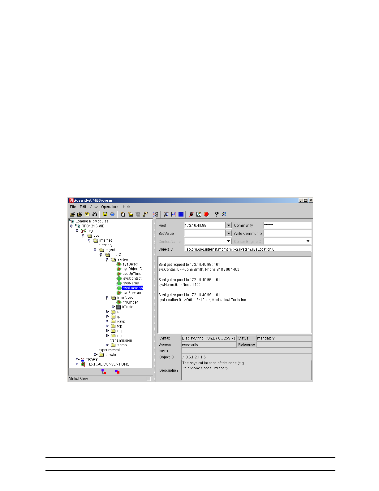
14 SNMP Configuration
Note Enter an empty string “” to get rid of any of the system settings.
The MIB-II system group values are accessible for reading and writing via the following SNMP objects:
•
.iso.org.dod.internet.mgmt.mib-2.system.sysContact
•
.iso.org.dod.internet.mgmt.mib-2.system.sysName
•
.iso.org.dod.internet.mgmt.mib-2.system.sysLocation
After setting these values according to 1 through 3 any SNMP MIB browser application should read the values using a get or get-next command as shown in figure 25.
The procedure to use the SNMP MIB browser is:
•
Enter the community string public into the Community field in the upper right corner of the window. For
safety reasons each entered character is displayed with a “*”.
•
Access any of the supported MIB system group object by using the GetNext button from the button bar
of the window.
Figure 25 ManageEngine MibBrowser displaying some of the System Group objects
724-746-5500 | blackbox.com
Page 96
Page 97

14 SNMP Configuration
Example: Setting the system group objects
In the following example the system information is set for later access via SNMP. See figure 25 for a typical
MIB browser application accessing these MIB-II system group objects representing the system information.
device>enable
device#configure
device(cfg)#system contact "Bill Anybody, Phone 818 700 1504"
device(cfg)#system location "Wiring Closet, 3rd floor"
device(cfg)#system hostname "device"
(cfg)#
After entering a host name the prompt on the CLI no longer displays the IP address of the Ethernet port
over which the Telnet session is running but shows the newly entered host name.
14.7 SETTING ACCESS COMMUNITY INFORMATION
SNMP uses one or more labels called community strings to delimit groups of objects (variables) that can
be viewed or modified on an LB52XA-R2. The SNMP data in such a group is organized in a tree structure
called a Management Information Base (MIB). A single device may have multiple MIBs connected together
into one large structure, and various community strings may provide read-only or read-write access to dif
ferent, possibly overlapping portions of the larger data structure. An example of a read-only variable might
be a counter showing the total number of octets sent or received through an interface. An example of a
read-write variable might be the speed of an interface, or the hostname of an LB52XA-R2.
-
Community strings also provide a weak form of access control in earlier versions of SNMP version 1 and 2.
SNMP version 3 provides much improved access control using strong authentication and should be pre
ferred over SNMP version 1 and 2 wherever it is supported. If a community string is defined, then it must be
provided in any basic SNMP query if the requested operation is to be permitted by the LB52XA-R2. Com
munity strings usually allow read-only or read-write access to the LB52XA-R2. In some cases, a given
community string will be limited to one group of read-only or read-write objects described in an individual
MIB.
In the absence of additional configuration options to constrain access, knowledge of the single community
string for the LB52XA-R2 is all that is required to gain access to all objects, both read-only and read-write,
and to modify any read-write objects.
Note Security problems can be caused by unauthorized individuals possessing knowledge of read-only com-
munity strings so they gain read access to confidential information stored on an affected device. Worse
can happen if they gain access to read-write community strings that allow unauthorized remote configu
ration of affected devices, possibly without the system administrators being aware that changes are
being made, resulting in a failure of integrity and a possible failure of LB52XA-R2 availability. To prevent
these situations, define community strings that only allow read-only access to the MIB objects should
be the default.
-
Choosing community names is like choosing a password. Do not use easily guessed ones; do not use
commonly known words, mix letters and other characters, and so on. If you do not intend to allow anyone to
use SNMP write commands on your system, then you probably only need one community name.
This procedure describes how to define your own SNMP community.
Mode: Configure
-
Step Command Purpose
1 device(cfg)#snmp community name { ro | rw }
Configures the SNMP community name with read-only or
read/write access
724-746-5500 | blackbox.com
Page 97
Page 98
14 SNMP Configuration
Use the no command option to remove a SNMP community setting.
Example: Setting access community information
In the following example the SNMP communities for the default community public with read-only access
and the undisclosed community Not4evEryOne with read/write access are defined. Only these valid com
munities have access to the information from the SNMP agent.
device(cfg)#snmp community public ro
device(cfg)#snmp community Not4evEryOne rw
Note If no community is set on the LB52XA-R2, accessing any of the MIB objects is not possible!
14.8 SETTING ALLOWED HOST INFORMATION
If a host has to access SNMP MIB objects on the LB52XA-R2, it explicitly needs the right to access the
SNMP agent. Therefore a host needs an entry, which allows accessing the LB52XA-R2. The host is identi
fied by its IP address and has to use a certain community string for security precautions.
Note The community which is to be used as security name to access the MIB objects has to be defined prior
to the definition of allowed hosts.
This procedure describes adding a host that is allowed to access the MIB of this system.
Mode: Configure
-
-
Step Command Purpose
device(cfg)#snmp host IP-address-of-device security-name
1
community
Configures a host that with IP address IPaddress-of-device can access the MIB, using
the security name community.
Use the no command option to remove a SNMP allowed host setting.
Example: Setting allowed host information
In the following example the host with IP address 172.16.224.45 shall be able to access the MIB using
community public as security name.
device(cfg)#snmp host 172.16.224.45 security-name public
14.9 SPECIFYING THE DEFAULT SNMP TRAP TARGET
An SNMP trap is a message that the SNMP agent sends to a network management station. For example,
an SNMP agent would send a trap when an interface's status has changed from up to down. The SNMP
agent must know the address of the network management station so that it knows where to send traps. It is
possible to define more than one SNMP trap target.
The SNMP message header contains a community field. The SNMP agent uses a defined community
name, which is inserted in the trap messages header sent to the target. In most cases the target is a NMS,
which only accepts a SNMP message header of a certain community.
This procedure describes how to define a SNMP trap target and enter community name.
724-746-5500 | blackbox.com
Page 98
Page 99

14 SNMP Configuration
Mode: Configure
Step Command Purpose
device(cfg)#snmp target IP-address-of-device
1
security-name community
Configures a SNMP trap target with IP-address-of-hostname device that receives trap messages using the
security name community on the target.
Use the no command option to remove s SNMP trap target setting.
Example: Specifying the default SNMP trap target
In the following example the NMS running on host with IP address 172.16.224.44 shall be defined as
SNMP trap target. Since the NMS requires that SNMP message headers have a community of Not4evEry
One the security-name argument is set accordingly.
device(cfg)#snmp target 172.16.224.44 security-name Not4evEryOne
14.10 DISPLAYING SNMP RELATED INFORMATION
Displaying the SNMP related configuration settings is often necessary to check configuration modifications
or when determining the behavior of the SNMP agent.
This procedure describes how to display information and configuration settings for SNMP.
-
Mode: Configure
Step Command Purpose
1 device(cfg)#show snmp Displays information and configuration settings for SNMP
Example: Displaying SNMP related information
This example shows how to display SNMP configuration information.
device(cfg)#show snmp
Hosts:
172.16.224.44 security-name public
Targets:
172.16.224.44 security-name Not4evEryOne
Communities:
public access-right ro
Not4evEryOne access-right rw
14.11 USING THE MANAGEENGINE SNMP UTILITIES
The ManageEngine SNMP utilities are a set of cross-platform applications and applets for SNMP and
Web-based network management. These utilities can be used for device, element, application and system
management. The following tools are the most useful:
•
MibBrowser—used to view and operate on data available through a SNMP agent on a managed
LB52XA-R2
•
TrapViewer—used to parse and view the received traps
The ManageEngine is a complete SNMP MibBrowser that enables the loading of MIBs, MIB browsing,
walking a MIB tree, searching MIBs and performing all other SNMP-related functions to users.
724-746-5500 | blackbox.com
Page 99
Page 100
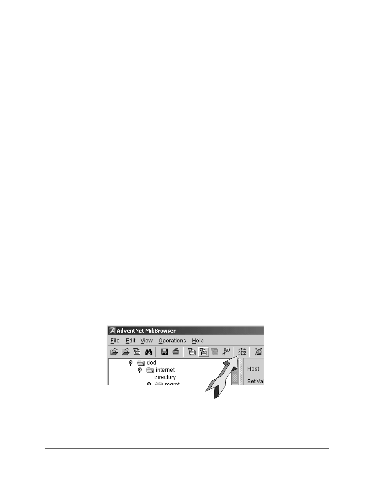
14 SNMP Configuration
Viewing and operating the data available through an SNMP agent on a managed device, e.g. a router,
switch, hub etc., is made possible by using the MibBrowser.
The TrapViewer is a graphical tool to view the Traps received from one or more SNMP agents. The Trap
viewer can listen to one or more port at a time and the traps can be sent from any host. Moreover the
TrapViewer contains a Trap parser editor, which is a tool to create a trap parser file. The Trap viewer parses
the file created using Trap parser editor to match each incoming traps with certain criteria. Since Traps typ
ically contain cryptic information, which is not easily understandable to the users, trap parsers are required
to translate or parse traps into understandable information.
14.11.1 USING THE MIBBROWSER
Figure 26 on page 100 depicts the primary window of the ManageEngine MibBrowser. It consists of a
menu bar, a toolbar, a left frame and a right frame.
The operations that can be performed by the MibBrowser are available in a series of buttons in the toolbar
on top of the MibBrowser's main window. The toolbar can be hidden or made visible using the options avail
able.
The menu bar has various options that perform the same operations as the options available in the toolbar.
The left frame holds the MIB tree. A MIB tree is a structure through which all the MIBs loaded can be
viewed. The MIB tree component enables us to traverse through the tree, view the loaded MIBs and learn
the definition for each SN. The ManageEngine MibBrowser allows loading additional MIB files in the text
format (the “my” file contains enterprise specific MIB definitions).
-
-
The right frame has labeled text fields to specify the basic parameters like host, community etc. and a
Result text area display to view the results.
There are three ways in which the primary window of the MibBrowser can be viewed. It can be viewed with
the result display, MIB description panel or multi-variable bind panel in the right frame. The view can be
altered in three ways.
•
The desired view can be set by the options provided in the display menu item under the view menu.
(View
Æ Display Æ).
•
The other way of altering the view is through the general settings panel in the settings menu item in
the edit menu. (Edit Æ Settings)
•
The same can be done through clicking the MibBrowser settings button on the toolbar. See figure 26.
Figure 26 ManageEngine MibBrowser Settings Button on the Toolbar
By default the MIB description display and the result display are visible in the MibBrowser.
724-746-5500 | blackbox.com
Page 100
 Loading...