

Page 1

ServSwitchServSwitch
January 2008
Page 2

SERVSWITCH™ FAMILY
1
Welcome to the ServSwitch™ Family!
Thank you for purchasing a BLACK BOX® ServSwitch DTX™
Control system! We appreciate your business, and we think you’ll
appreciate the many ways that your new DTX Control System will
save you money, time, and effort.
The BLACK BOX® ServSwitch DTX™ Control system is a
secure, web browser-based, centralized enterprise management
solution that allows users to remotely manage and monitor multiple
ServSwitch DTX5000 systems. Each ServSwitch DTX5000 system
allows desktop users access a full computer experience from
anywhere on the corporate TCP/IP network, while maintaining the
computers securely housed in a corporate data center. This desktop
experience includes access for the desktop user to keyboard,
mouse, both digital and analog video, and audio devices.
This solution can be deployed as a point-to-point extender system
or may over-laid on the standard 100 Mbps/1 Gbps TCP/IP
network.
The ServSwitch™ family from BLACK BOX - the one-stop
answer for all your KVM switching needs!
*
This manual will tell you all about your new ServSwitch DTX™
Control system, including how to install, operate and troubleshoot
it. For an introduction to the ServSwitch DTX™ Control system
see Chapter 2.
Page 3

SERVSWITCH™ FAMILY
2
Page 4

SERVSWITCH DTX™ CONTROL USER GUIDE
3
USA Notification
Warning: Changes or modifications to this unit not expressly approved by the party
responsible for compliance could void the user’s authority to operate the equipment.
Note: This equipment has been tested and found to comply with the limits for a Class A
digital device, pursuant to Part 15 of the FCC Rules. These limits are designed to provide
reasonable protection against harmful interference when the equipment is operated in a
commercial environment. This equipment generates, uses and can radiate radio frequency
energy and, if not installed and used in accordance with the instruction manual, may cause
harmful interference to radio communications. Operation of this equipment in a residential
area is likely to cause harmful interference in which case the user will be required to
correct the interference at his own expense.
Canadian Notification
This class A digital apparatus complies with Canadian ICES-003.
Cet appareil numérique de la classe A est conforme à la norme NMB-003 du Canada.
Safety and EMC Approvals and Markings
FCC Class B, EN 55022 Class B, EN 61000-3-2/-3-3, CISPR 22 Class B, EN 55024/
CISPR 24, (EN 61000–4–2, EN 61000-4-3, EN 61000-4-4, EN 61000-4-5, EN 61000-4-6,
EN 61000-4-8, EN 61000-4-11), EN 60950/IEC 60950-Compliant, UL Listed (USA),
CUL Listed (Canada), TUV Certified (Germany), CE Marking (Europe)
Page 5

SERVSWITCH DTX™ CONTROL USER GUIDE
i
ServSwitch DTX
TM
Control
User Guide
Page 6

SERVSWITCH DTX™ CONTROL USER GUIDE
ii
Instructions
This symbol is intended to alert the user to the presence of important
operating and maintenance (servicing) instructions in the literature
accompanying the Management Appliance.
Page 7

SERVSWITCH DTX™ CONTROL USER GUIDE
iii
1. Specifications...................................................................................................1
2. Product Overview.............................................................................................3
2.1 Introduction....................................................................................................................3
2.2 Features and Benefits.....................................................................................................3
2.3 System Components ......................................................................................................4
2.4 Supported Units .............................................................................................................4
2.5 Explorer Window...........................................................................................................4
2.6 Internet Explorer Considerations...................................................................................7
2.7 Firewalls.........................................................................................................................7
3. Hardware Installation and Setup ....................................................................9
3.1 Introduction....................................................................................................................9
3.2 Safety Precautions..........................................................................................................9
3.3 Rack Mount Safety Considerations ...............................................................................9
3.4 Cabling Installation, Maintenance and Safety Tips .......................................................9
3.5 Management Appliance Configuration........................................................................10
3.6 Installing the Management Appliance .........................................................................12
3.7 Using the serial port to configure the IP addresses of the Management Appliance ....12
4. Managing Units ..............................................................................................15
4.1 Introduction..................................................................................................................15
4.2 Accessing the Management Appliance Web Interface................................................15
4.3 Units View Windows...................................................................................................15
4.4 Adding Units................................................................................................................18
4.5 Managing units ............................................................................................................21
4.6 Configuring Network Settings for an DTX Transmitter or Receiver ..........................22
4.7 Managing Firmware Upgrades ....................................................................................25
4.8 Managing Target Computers........................................................................................25
4.9 Active Media Sessions.................................................................................................27
4.10 Department and Location Groups..............................................................................27
5. Managing Users .............................................................................................29
5.1 Introduction..................................................................................................................29
5.2 User Accounts Windows .............................................................................................29
5.3 Adding User Accounts.................................................................................................29
5.4 Managing User Accounts.............................................................................................31
5.5 Managing User Access to Target Computers ..............................................................32
5.6 User Contact Details ....................................................................................................34
5.7 User Authentication Services.......................................................................................34
6. Advanced Operations....................................................................................37
6.1 DTX Transmitter Pooling ............................................................................................37
Page 8

SERVSWITCH DTX™ CONTROL USER GUIDE
iv
6.2 Backup and Restore .....................................................................................................37
6.3 Management Appliance Upgrade ................................................................................38
6.4 Firmware Management ................................................................................................38
6.5 Resetting Administrator Password...............................................................................39
7. Events and Event Logs..................................................................................41
7.1 Introduction..................................................................................................................41
7.2 Event Severity and Categories.....................................................................................41
7.3 Displaying the Event Log ............................................................................................42
7.4 Changing the Event Log Retention Period ..................................................................42
7.5 Creating an Event Log .csv File...................................................................................42
8. Technical Support..........................................................................................45
Page 9

CHAPTER 1: SPECIFICATIONS
1
1. Specifications
During the course of this product's lifetime, modifications might be made to its hardware
or firmware that could cause these specifications to change without notice.
ServSwitch DTX™ Control Product Specifications
Network Connection
Number 2
Ty pe Ethernet, 10BaseT, 100BaseT, GigE
Connector RJ-45
Serial Port
Number 1
Ty pe RS-232 serial
Connector DB9 male
Mechanical
H x W x D 4.3 x 42.7 x 35.6 cm (1.7 x 16.8 x 14 in), 1 U form factor
Weight 5.9 kg (13 lb)
Power
AC Input Voltage 100 to 240 VAC
Rated Input Current 4A maximum
Rated Input Frequency 50 to 60 Hz
Rated Output Power 260 W maximum
Rated Output Voltages +3.3 V (15 A), +5 V (25 A), +12V (18A), -12 V (1A)
BTU Rate 1400 Bus/hour (for rated output power of 260 W)
Environmental
Temperature
0° to 35° Celsius (32° to 95° Fahrenheit) operating
Humidity
10 to 90% noncondensing operating
Safety and EMC
Approvals and
Markings
Electromagnetic
Emissions
FCC Class B, EN 55022 Class B, EN 61000-3-2/-3-3, CISPR 22
Class B
Page 10

SERVSWITCH DTX™ CONTROL USER GUIDE
2
ServSwitch DTX™ Control Product Specifications (continued)
Electromagnetic
Immunity
EN 55024/CISPR 24, (EN 61000-4-2, EN 61000-4-3,
EN 61000-4-4, EN 61000-4-5, EN 61000-4-6, EN 61000-4-8,
EN
61000-4-11)
Safety
EN 60950/IEC 60950-Compliant, UL Listed (USA), CUL Listed
(Canada), TUV Certified (Germany), CE Marking (Europe)
Page 11

CHAPTER 2: PRODUCT OVERVIEW
3
2. Product Overview
2.1 Introduction
The ServSwitch DTX™ Control (Management Appliance) is a secure, web
browser-based, centralized enterprise management solution that allows users to remotely
manage and monitor multiple ServSwitch DTX5000 systems.
The addition of this appliance allows the combination of DTX Transmitters and DTX
Receivers to operate in Desktop Mode. This mode allows a user to log in to any DTX
Receiver and the system will connect automatically to the DTX Transmitter that has been
assigned to that user.
A ServSwitch Extender system comprises two units - an DTX Receiver that is located at
the user’s desk, and an DTX Transmitter that is attached to a remote computer (target
computer). For detailed information about the ServSwitch DTX5000 system see the
Black
Box ServSwitch DTX5000 User Guide. This manual refers to the list of products
in
Table 2.1.
2.2 Features and Benefits
Web-based access and control
The Management Appliance provides secure “point-and-click” web browser-based access
to control virtually any data center device using managed appliances from Management
Appliance software clients that may be located anywhere in the world.
Secure authentication and communication
Secure Socket Layer (SSL) encryption is used to encrypt data traveling within the
Management Appliance system. Users are authenticated using the Management Appliance
internal database.
Unit and user management
The Management Appliance provides centralized network access, control and security for
managed units and users.
2.3 System Components
Management Appliance
The Management Appliance provides a centralized database for storing configuration,
user, unit and system information. Through this the administrator can add, remove, delete
Table 2.1: List of Products
Name Model
Management Appliance
ServSwitchTM DTX Control
DTX Transmitter DTX5000-T
DTX Receiver DTX5000-R
ServSwitch Extender DTX5000 Digital Extender
Page 12

SERVSWITCH DTX™ CONTROL USER GUIDE
4
and change settings for managed appliances and users. The Management Appliance also
allows connection brokering to control the establishment, removal, and monitoring of
associations between DTX Receivers and DTX Transmitters. In addition, it provides
access to a range of administration options that include services for authentication, access
control, logging events and monitoring.
Administrators may connect to the Management Appliance via a web browser and use the
Management Appliance Explorer window to communicate with the system.
Management Appliance Software Client
A Management Appliance Software Client is a computer with a web browser that can
access the Management Appliance.
The Management Appliance supports Microsoft® Internet Explorer version 6.0 SP2.
2.4 Supported Units
For management functions, the Management Appliance uses HTTPS (Hypertext Transfer
Protocol with SSL encryption) to interact with the ServSwitch DTX5000 system.
The Management Appliance supports DTX Transmitters and DTX Receivers.
DTX Transmitter
The DTX Transmitter connects externally to the video, audio and USB ports of the target
computer.
The DTX Transmitter is attached directly to the target computer and draws its power from
two USB ports on the remote computer. This removes the need for additional power
supply connections at the rack.
The DTX Transmitter captures, compresses, and encrypts the computer’s media stream
and transmits them to the DTX Receiver over a standard TCP/IP network.
DTX Receiver
The DTX Receiver enables the desktop user’s keyboard, video, mouse and audio devices
to connect to the ServSwitch Extender system. The DTX Receiver is available as a
desktop user station.
Target Computer
A target computer is the remote computer or server that a user can connect to by logging
into an DTX Receiver.
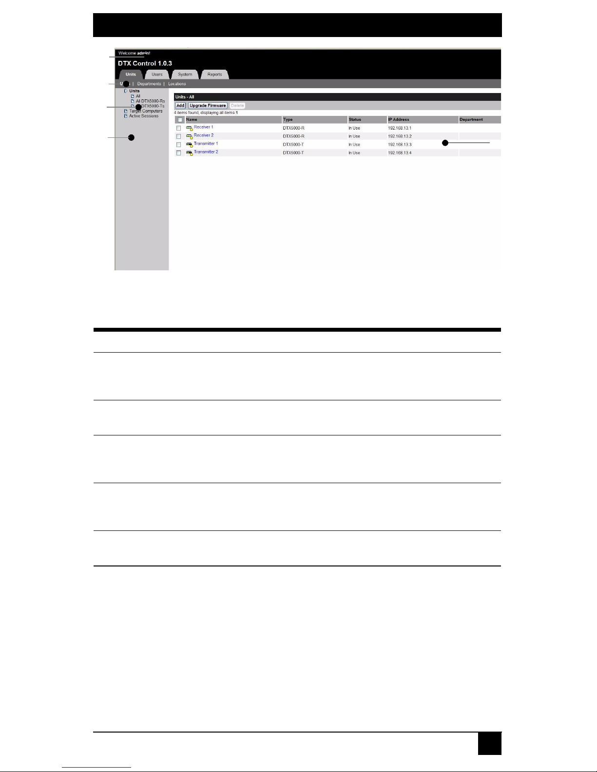
2.5 Explorer Window
When a user has been logged in and authenticated, the Explorer window is displayed.
From the Explorer window, you can view, access and manage units, users and the
ServSwitch DTX Control System.
Figure 2-1 shows the Explorer window areas, which are described in Table 2.2.
Page 13
CHAPTER 2: PRODUCT OVERVIEW
5
Figure 2-1. Explorer Window Areas
Table 2.2: Explorer Window Area Descriptions
Letter Description
A
Top option bar - Use the top option bar to log out of a software session, or to
access online help. The name of the logged in user is displayed on the left side of
the top options bar.
B
Tab bar - Use the tab bar to display and manage units, user accounts, system
settings, and reports.
C
Top navigation bar - The options in the top navigation bar vary depending on the
active tab in the tab bar. Topics relevant to each selection display in the side
navigation bar.
D
Side navigation bar - Use the side navigation bar to select system information to
display or edit in the content area. The side navigation bar contains arrows that
affect its display; see “Using the side navigation bar” on page
5.
E
Content area - The information specified by the tab bar, top navigation bar and
side navigation bar selections is displayed and changed in the content area.
B
C
A
D
E
Page 14

SERVSWITCH DTX™ CONTROL USER GUIDE
6
Using the side navigation bar
The side navigation bar is used to display windows that specify settings or perform
operations. The contents of the side navigation bar vary, depending on the tab and top
navigation bar options that are in use.
Figure 2-2 shows the location of side navigation bar arrow.
Figure 2-2. Example Side Navigation Bar
NOTE:
Menus are static and cannot be expanded or collapsed
The arrows displayed indicate that a number of sub-options are available. You can display
these items by clicking the main link. Where no arrow is displayed, clicking the link
brings you directly to the option you have selected.
Displaying pages
Multiple page windows contain menu options that may be used to quickly navigate from
one display to another.You can click to enable the Select All checkbox to select all items
on a page. Enabling this checkbox selects all the items listed on a page regardless of
whether the entire page is visible. However, for multi-page displays, items listed on other
pages will not be included in the selection.
Refreshing a window
All screens that show lists, units, sessions and target computers automatically refresh
every 10 seconds.
Using keyboard commands
In addition to using a mouse, you can use certain keyboard commands to select and
change items in windows.
Table 2.3 lists general keyboard commands that can be used.
Table 2.3: General Keyboard Commands
Key Description
Ta b Transfers focus to the next control in the window, including the calendar
Shift-Tab Transfers focus to the previous HTML control
Unit Views
Units
All
DTX5000-Ts
Target Computers
Active Sessions
DTX5000-Rs
Page 15

CHAPTER 2: PRODUCT OVERVIEW
7
2.6 Internet Explorer Considerations
The Management Appliance operates using the default Internet Explorer settings. In the
event that the default Internet Explorer settings have been altered, SSL and Javascript
must be enabled to successfully access the Management Appliance.
2.7 Firewalls
To access the Management Appliance through a firewall, you must ensure that the firewall
uses the default HTTPS port 443.
Page 16

SERVSWITCH DTX™ CONTROL USER GUIDE
8
Page 17

CHAPTER 3: HARDWARE INSTALLATION AND SETUP
9
3. Hardware Installation and Setup
3.1 Introduction
This chapter describes how to install and set up the ServSwitch DTX™ Control
(Management Appliance) .
NOTE:
The first time you access the Management Appliance, enter admin as the user name and password as
the password. The admin account is authorized to perform all configuration and access all managed units
and cannot be removed or renamed.
3.2 Safety Precautions
To avoid potentially fatal shock hazard and possible damage to equipment, please observe
the following precautions:
• Do not use a 2-wire power cord in any product configuration.
• Test AC outlets at the target computer and monitor for proper polarity and grounding.
• Use only with grounded outlets.
NOTE:
The AC inlet is the main power disconnect.
3.3 Rack Mount Safety Considerations
• Elevated Ambient Temperature: If installed in a closed rack assembly, the operating
temperature of the rack environment may be greater than room ambient. Use care not
to exceed the rated maximum ambient temperature of the switch.
• Reduced Air Flow: Installation of the equipment in a rack should be such that the
amount of airflow required for safe operation of the equipment is not compromised.
• Mechanical Loading: Mounting of the equipment in the rack should be such that a
hazardous condition does not exist due to uneven mechanical loading.
• Circuit Overloading: Consideration should be given to the connection of the
equipment to the supply circuit and the effect that overloading of circuits might have
on overcurrent protection and supply wiring. Consider equipment nameplate ratings
for maximum current.
• Reliable Earthing: Reliable earthing of rack mounted equipment should be
maintained. Pay particular attention to supply connections other than direct
connections to the branch circuit (for example, use of power strips).
3.4 Cabling Installation, Maintenance and Safety Tips
The following is a list of important safety considerations that should be reviewed prior to
installing or maintaining your cables:
• Maintain the twists of the pairs all the way to the point of termination, or no more that
one-half inch untwisted. Do not skin off more than one inch of jacket while
terminating.
• If bending the cable is necessary, make it gradual with no bend sharper than a one
inch radius. Allowing the cable to be sharply bent or kinked can permanently damage
the cable’s interior.
Page 18

SERVSWITCH DTX™ CONTROL USER GUIDE
10
• Dress the cables neatly with cable ties, using low to moderate pressure. Do not over
tighten ties.
• Cross-connect cables where necessary, using rated punch blocks, patch panels and
components. Do not splice or bridge cable at any point.
• Keep CAT 5 cable as far away as possible from potential sources of EMI, such as
electrical cables, transformers and light fixtures. Do not tie cables to electrical
conduits or lay cables on electrical fixtures.
• Always test every installed segment with a cable tester. “Toning” alone is not an
acceptable test.
• Always install jacks so as to prevent dust and other contaminants from settling on the
contacts. The contacts of the jack should face up on the flush mounted plates, or left/
right/down on surface mount boxes.
• Always leave extra slack on the cables, neatly coiled in the ceiling or nearest
concealed location. Leave at least five feet at the work outlet side and 10 feet at the
patch panel side.
• Choose either 568A or 568B wiring standard before beginning. Wire all jacks and
patch panels for the same wiring scheme. Do not mix 568A and 568B wiring in the
same installation.
• Always obey all local and national fire and building codes. Be sure to firestop all
cables that penetrate a firewall. Use plenum rated cable where it is required.
3.5 Management Appliance Configuration
A typical Management Appliance configuration, as illustrated in Figure 3-1, includes the
appliance and the transmitters and receivers connected to the local area network (LAN).
A
terminal, or a workstation running a terminal emulation program, is connected to the
serial port for configuring basic network settings. The Management Appliance,
transmitters and receivers, and user accounts are then configured from the browser
interface to the Management Appliance.
Page 19

CHAPTER 3: HARDWARE INSTALLATION AND SETUP
11
Figure 3-1. Management Appliance Configuration
Number Description
1 Management Appliance
2 LAN
3 LAN Port 1
4 LAN Port 2
5 Transmitters and receivers
6 CAT 5 Cables
7 Power
8 Connection to the Serial Port
9 Terminal or Workstation (for Configuration)
2
2
5
5
6
3
4
1
7
8
9
Page 20

SERVSWITCH DTX™ CONTROL USER GUIDE
12
3.6 Installing the Management Appliance
NOTE:
The Management Appliance may be rack mounted in a 1U configuration.
To connect and power up the Management Appliance:
1. Install the Management Appliance on the top of the server rack or at the location
from which it will be used.
2. The LAN Port 1 Ethernet port on the back panel of the Management Appliance
should be connected to the LAN to which the transmitters and receivers are
connected.
NOTE:
All DTX Transmitters and DTX Receivers must be connected to the same LAN.
3. Attach one end of the supplied power cord into the back panel of the Management
Appliance and attach the other end to an appropriate AC power source.
4. Power up the Management Appliance.
NOTE:
The DTX Transmitters and DTX Receivers must be connected to LAN port 1. However, you can access the
Management Appliance using the browser on a computer connected to either LAN port 1 or LAN port 2.
WARNING: To reduce the risk of electric shock or damage to your equipment:
- Do not disable the power cord grounding plug. The grounding plug is an important
safety
feature.
- Plug the power cord into a grounded (earthed) outlet that is easily accessible at all times.
- Disconnect the power from the target computer by unplugging the power cord from either
the electrical outlet or the target computer.
3.7 Using the serial port to configure the IP addresses
of the Management Appliance
To assign an IP address to the Management Appliance, you must first establish a
connection to the serial menu. You can then use the options on the serial console menu to
configure the network settings for each of the LAN Ports on the Management Appliance.
NOTE:
If you are connecting to only one LAN, only LAN port 1 needs to be configured
Perform the following procedure to configure the IP address of the Management
Appliance.
To configure the IP address of the Management Appliance:
1. Connect a terminal or a workstation that is running a terminal emulation program to
the serial port on the back panel of the Management Appliance.
2. Start a session with the following port settings:
• Serial speed: 9600 bps
• Data length: 8 data bits
• Parity: None
• Stop Bits: 1
• Flow Control: None
Page 21

CHAPTER 3: HARDWARE INSTALLATION AND SETUP
13
3. Once a connection is established, a serial console menu appears.
4. You then type 2 to configure any of the following network settings:
• Set eth speed
• Choose using DHCP or defining an IP address
• Type subnet mask
• Type gateway IP address
• Select default gateway
• Define primary DNS and secondary DNS
NOTE:
The IP address on LAN Port 1 must not change during operation of the appliance. Therefore always
configure LAN port 1 with a static IP address or, if using DHCP, ensure that the IP addresses are assigned
with unlimited lease times. There is no restriction on how LAN port 2 can be configured. It is also possible
to configure DNS on the Management Appliance, if it is required for administrator access through a web
browser.
NOTE:
If DHCP is selected, the Management Appliance must be re-booted for the change to take effect.
5. Set time and date on the serial menu.
6. Type 0 to exit.
Page 22

SERVSWITCH DTX™ CONTROL USER GUIDE
14
Page 23

CHAPTER 4: MANAGING UNITS
15
4. Managing Units
4.1 Introduction
The ServSwitch DTX™ Control (Management Appliance) is used to manage networks of
DTX Receivers and DTX Transmitters (units). Using the Management Appliance, an
administrator can add units, view and edit unit properties and initiate a variety of
other
operations.
4.2 Accessing the Management Appliance Web Interface
To access the Management Appliance web interface:
1. Open Microsoft® Internet Explorer.
2. In the Address bar, type the url for the Management Appliance. The address will be
in the format http://<addr>>/dtview/ where <<addr>> is the IP address assigned to
the Management Appliance LAN port 1.
NOTE:
If DNS is enabled the address is the fully qualified host name assigned to the Management Appliance.
3. Press Return. The Management Appliance login screen appears.
4. Enter login user name and password. Default username is ‘admin’. Default password
is ‘password’. It is recommended that the default password is changed.
NOTE:
If you have forgotten your password, contact Black Box Technical Support.
4.3 Units View Windows
The Units View windows display the list of units that have been added to the Management
Appliance database.
Units are displayed in a table format with column headings. You can use the checkbox to
the left of each unit name to select/deselect the unit for an operation. To select all the units
on a page, click the checkbox at the left of all the column headings at the top of the list -
this is usually to the left of the Name column. Clicking the Select All checkbox will
automatically enable the checkboxes for all units on that page. To deselect items that were
previously selected, click to select the checkbox.
If the list of units spans more than one page, units on subsequent pages will not be selected.
Types of Units View windows
There are several types of Units View windows, which are accessed by clicking tabs and
side navigation bar links.
• All Units: The Units - All window lists all managed units.
• Unit Type: Unit Type windows list all managed units of a particular type (for
example, All DTX Receivers or All DTX Transmitters).
The following unit types will always be visible on the side navigation bar:
• Units
• All
• All DTX Receivers
Page 24

SERVSWITCH DTX™ CONTROL USER GUIDE
16
• All DTX Transmitters
• Target Computers: The Target Computers - All window lists all target
computers.
• Active Sessions: An active session starts when a connection is made between a
transmitter and a receiver. This window lists the current sessions, each session
start time, the duration of each session, the user who initiated the session, the
DTX Transmitter used, the DTX Receiver used and the target computer used.
NOTE:
An authorized pair is a pairing of an DTX Transmitter and a target computer that has been
accepted by the administrator. An unauthorized pair is a pairing of an DTX Transmitter and a
target computer that has not been accepted by the administrator as a desired pairing. An
unauthorized pairing can occur after initial discovery of a device pair or if the DTX
Transmitter was inserted into the wrong target computer.
• Departments and Locations: The Management Appliance provides a means to
attach logical location identifiers to units. This makes it easier for administrators to
track and locate units within their organization. There are two types of logical
location identifiers:
• Departments - Units that have been assigned to a department.
• Locations - Units that have been assigned to a location.
Accessing Units View windows
To access Units View windows:
• Click the Units tab.
• To display managed units:
•Click Units in the side navigation bar. The Units - All window will
open.
• To display a Unit Type window, click one of the Unit type links in the side
navigation bar. You can view a summary of all units - all DTX Receivers or all
DTX Transmitters - by clicking the links in the side navigation bar.
• To display target computers:
• Click Target Computers in the side navigation bar. The Target
Computers - All window will open. This window lists all target
computers in the system.
• To display active media sessions:
•Click Active Sessions in the side navigation bar. The Active Media Sessions
window will open. This window lists all the users that are currently accessing
DTX Transmitters, and shows which DTX Transmitter is being accessed by
which user. It also displays start times and session duration.
Units View windows fields
The following fields will appear in Units View window.
• Name - Name of the unit as defined in the Management Appliance database. Click
the name to display or change unit information.
Page 25

CHAPTER 4: MANAGING UNITS
17
• Type - Type of managed unit. Managed unit types cannot be changed.
• Status - Current operating status of a unit. Tabl e 4.1 lists and describes the possible
values.
Table 4.1: Unit Status Values
• IP Address - The IP address of a managed unit.
• Department - The name of the department to which a managed unit has been
assigned.
• Location - The name of the location to which a managed unit has been assigned.
• Revision - The current firmware version that is installed on a managed unit.
• DTX Transmitter name - The name of the DTX Transmitter. Click the name of the
DTX Transmitter to display or change DTX Transmitter information.
• DTX Transmitter address - The IP address of the DTX Transmitter. Click the name
of the DTX Transmitter to display or change information.
• Target Computer name - The name of the target computer within an DTX
Transmitter-target computer pair. Click the name of the target computer to display or
change target computer information.
• Target Computer address - The IP address of the target computer within an DTX
Transmitter-target computer pair is the same as that of the associated DTX
Transmitter. Click the IP address of the target computer to display or change target
computer information.
Unit type Status and Icon Description
Managed units Idle
Unit is powered up, can be communicated
with, and is not associated with an active
media session.
Managed units In Use Unit is associated with a session.
Managed units Upgrading Unit firmware is being upgraded.
Managed units Not Responding
The Management Appliance cannot
contact the unit.
Target Computers Idle
Target computer is not associated with an
active media session.
Target Computers In Use
Target computer is associated with an
active media session.
Active Session Active
The active session is running and the units
are responding.
Active Session Not Responding
The units involved in the active session are
not responding. (If an active session is not
responding for more than 20 minutes it will
be automatically deleted.)
Page 26

SERVSWITCH DTX™ CONTROL USER GUIDE
18
Unit Overview windows
The Unit Overview window contains the following information about an individual unit:
• Managed Units - Name, Type, EID, MPN, Address, MAC address, and Status of the
managed units and the tools that can be used to:
•Reboot
• Upgrade firmware
The available tasks depend on the type of managed unit.
• Authorized Target Computer - Display Name, Name, Type, Address and MAC
address.
To view overview information for a unit:
In a Units View window containing units, click the name of a unit. The Units Overview
window will open.
To view overview information for a target computer:
In a Units View window containing target computers, click the name of a target
computer. The Overview window will open.
4.4 Adding Units
Before you can manage units in the Management Appliance, you must first add them to
the Management Appliance database. You can add units to the Management Appliance
database using the Add Unit Wizard.
The Add Unit Wizard
• You can use the Add Unit Wizard to:
• Add a single unit
• Discover units within an IP address range
• Discover units on an IP subnet address
The Add Unit Wizard can be launched from the following Units View windows:
• Units - All
• Units - All DTX Receivers
• Units - All DTX Transmitters
• Target Computers - All
• Authorized DTX Transmitter - Target Computer Pairs
Adding a single Appliance
This procedure is valid for DTX Transmitters and DTX Receivers.
NOTE:
A unit can only be added to the Management Appliance database if it is powered up and attached to the
network.
To add a single unit that already has an IP address:
1. In a Units View window containing managed units, click Add. The Add Unit
Wizard
Welcome Window will open. Click Next.
Page 27

CHAPTER 4: MANAGING UNITS
19
2. The Select Add Unit Procedure window will open. Click Add a single unit, then
click Next.
3. The Select Unit Type window will open. Select a unit from the product list, then
click Next.
4. The Select Address Configuration of Unit window will open. Click Yes, the
<Managed Unit Type> does have an addr e s s and type the address of the unit. Click
Next.
5. The Search Results window will open. The name and MAC address of the
discovered unit will be displayed. Click Next.
6. The Completed Successfully window will open. To exit the Add Unit Wizard, click
Finish.
To add a single unit that does not yet have an IP address (for example, if the
IP address is lost):
1. In a Units View window containing managed units, click Add. The Add Unit
Wizard
Welcome Window will open. Click Next.
2. The Select Add Unit Procedure window will open. Click Add a single unit, then
click Next.
3. The Select Unit Type window will open. Select a unit from the product list, then
click Next.
4. The Select Address Configuration of Unit window will open. Click No, the
(Managed Unit Type) does not have an address. Click Next.
5. The Configure Unit Network Settings window will open.
a. Type the IP address and subnet mask, in standard dot notation
(xxx.xxx.xxx.xxx), for the managed unit.
b. Optionally, type a gateway in standard dot notation (xxx.xxx.xxx.xxx).
c. Click Next.
6. The Add Discovered Unit window will open. Select the discovered unit from the list,
then click Next.
7. The Completed Successfully window will open. To exit the Add Unit Wizard, click
Finish.
Adding units from a range of IP addresses
This procedure is valid for DTX Transmitters and DTX Receivers.
To add a unit from a range of IP addresses:
1. In a Units View window containing managed units, click Add. The Add Unit
Wizard
Welcome Window will open. Click Next.
2. The Select Add Unit Procedure window will open. Click Discover units within an
IP address range, then click Next.
3. The Enter IP Address Range window will open.
a. Type the IP address in standard dot notation (xxx.xxx.xxx.xxx), from which to
begin the search.
Page 28

SERVSWITCH DTX™ CONTROL USER GUIDE
20
b. Type the IP address in standard dot notation (xxx.xxx.xxx.xxx), at which to end
the search.
c. Click Next.
4. The Management Appliance will search for managed units within the IP address
range. When the search is completed, the Select Units to Add window will open,
listing the results.
5. Add units:
• To add one or more managed units, select the managed units in the Units Found
list, then click Add. The managed units will be moved to the Units to Add list.
• To remove one or more managed units, select the managed units in the Units to
Add list, then click Remove. The managed units will be moved to the Units
Found list.
6. Click Next.
7. The Completed Successfully window will open. To exit the Add Unit Wizard, click
Finish.
Adding Units on an IP Subnet
This procedure is valid for DTX Transmitters and DTX Receivers.
To add a unit from a Subnet:
1. In a Units View window containing managed unit, click Add. The Add Unit Wizard
Welcome Window will open. Click Next.
2. The Select Add Unit Procedure window will open. Click Discover uni ts on an IP
subnet address, then click Next.
3. The Enter Subnet Address Window will open.
4. Type the IP address in standard dot notation (xxx.xxx.xxx.xxx) and click Next.
5. The Management Appliance searches for managed units within the IP subnet address
range. When the search is completed, the Select Units to Add window will open, list
-
ing the results.
6. Add or remove units
• To add one or more managed units, select the managed units in the Units Found
list, then click Add. The managed units will be moved to the Units to Add list.
• To remove one or more managed units, select the managed units in the Units to
Add list, then click Remove. The managed units will be moved to the Units
Found list.
7. Click Next.
8. The Completed Successfully window will open. To exit the Add Unit Wizard, click
Finish.
Deleting Units
When you delete a unit, it is removed from the Management Appliance database, and all
associated connections will also be deleted. It is recommended that active sessions are
deleted before units are deleted.
Page 29

CHAPTER 4: MANAGING UNITS
21
To delete a unit:
1. In a Units View window, click to select the checkbox next to the unit name. To delete
all units on the page, click to select the checkbox to the left of name at the top of the
list.
2. Click Delete. The unit is immediately removed from the Management Appliance
database and disappears from the list.
4.5 Managing units
All configuration options under the Unit Settings menu in the side navigation window
involve live communication with an DTX Transmitter or DTX Receiver. The transmitter
or receiver must be powered up, discovered and added for the Management Appliance to
display its properties.
If the Management Appliance cannot communicate with an DTX Transmitter or DTX
Receiver, it will display the following communication error: “An error was encountered
communicating with the Unit. Please check the unit’s network settings and connectivity.”
Viewing Unit Overview Information
To view a summary of all units managed by the Management Appliance:
1. Click the Units tab. The Units - All window will open.
2. A list is displayed of all the units (i.e., DTX Transmitters and DTX Receivers) that
are managed by the Management Appliance.
3. To view a list that contains only DTX Transmitters select the All DTX Transmitters
navigation option.
4. To view a list that contains only DTX Receivers select the All DTX Receivers naviga-
tion option.
The Unit Overview window
The Unit Overview window contains the following information about an individual unit:
•Name
• Type (DTX Transmitter, DTX5000-T, or DTX Receiver, DTX5000-R)
• IP address
• MAC address
• Unit Session Status
The Unit Overview window enables you to:
• Change the name of a unit
• Reboot a unit
• Upgrade the firmware of a unit
To access the Unit Overview window:
1. Click the Units tab.
2. A list is displayed of all the units that are managed by the Management Appliance.
3. Click the unit name about which you require information.
4. The Unit Overview window will open.
Page 30

SERVSWITCH DTX™ CONTROL USER GUIDE
22
To change the name of a unit:
1. Click the Units tab.
2. A list is displayed of all the units that are managed by the Management Appliance.
3. Click the unit name about which you require information.
4. The Unit Overview window will open.
5. Type a name for the managed unit. (You cannot change the type.)
6. Click Save and then click Close. The Units - All window will open.
Changing Unit Properties
The Management Appliance enables you to manage the following properties for each unit:
• Department
• Location
• Primary contact details (name, telephone number)
To change the properties of a unit:
1. Click the Units tab.
2. A list is displayed of all the units that are managed by the Management Appliance.
3. Click the unit name about which you require information.
4. The Unit Overview window will open.
5. Select Properties from the side navigation bar.
6. The Unit Properties window will open. This window displays all the general
properties of the unit. Edit the properties you wish to change.
NOTE:
Part Number (MPN), Serial Number (EID) and Model are read-only values. These values are read from
a unit during discovery and cannot be changed.
7. Click Save and then click Close.
8. The updated properties are displayed.
4.6 Configuring Network Settings for an DTX
Transmitter or Receiver
The administrator can use the Management Appliance to change a unit's IP address,
Subnet Mask, Default Gateway and DHCP status. Once you have implemented the
changes the unit will reboot.
To change the network settings of a managed unit:
1. Click the Units tab.
2. A list is displayed of all the units that are managed by the Management Appliance.
3. Click the unit name whose network settings you wish to change.
4. The Unit Overview window will open.
5. Click Network. The Unit Network Settings window will open. To change
information:
• Type an address, in standard dot notation (xxx.xxx.xxx.xxx).
• Type a subnet, in standard dot notation (xxx.xxx.xxx.xxx).
• Type a gateway, in standard dot notation (xxx.xxx.xxx.xxx).
Page 31

CHAPTER 4: MANAGING UNITS
23
• Enable or disable DHCP.
6. Click Save and then click Close.
Authentication Server Settings
Authentication server settings are applied only to DTX Receivers. The Authentication
Servers’ menu item in the side navigation bar will only be displayed if the unit type is an
DTX Receiver.
To view Unit Authentication Server settings:
1. Click the Units tab.
2. A list is displayed of all the units that are managed by the Management Appliance.
3. Click the DTX Receiver name about which you require information.
4. The Unit Overview window will open.
5. Click Authentication Servers under Unit Settings in the side navigation bar.
6. The Unit Authentication Server Settings window will open. This window displays
the address of the authentication server used by the unit.
To change Unit Authentication Server settings:
1. Click the Units tab.
2. A list is displayed of all the units that are managed by the Management Appliance.
3. Click the unit name about which you require information.
4. The Unit Overview window will open.
5. Click Authentication Servers under Unit Settings in the side navigation bar.
6. The Unit Authentication Server Settings window will open. This window displays
the address of the authentication server used by the unit. To change information:
• Type an address, in standard dot notation (xxx.xxx.xxx.xxx).
7. Click Save.
Viewing Version Information
To view version information for a unit:
1. Click the Units tab.
2. A list is displayed of all the units that are managed by the Management Appliance.
3. Click the unit name about which you require information.
4. The Unit Overview window will open. In the Unit Settings in the side navigation
bar click Versions. The Unit Version Information window will open, containing the
following information:
• Release - The overall unit build release number.
• Application - The version of the application software deployed on the unit.
• Boot - The version of the boot software deployed on the unit.
• FPGA - The version of the FPGA deployed on the unit.
Rebooting a unit
To reboot a unit:
1. Click the Units tab.
2. A list is displayed of all the units that are managed by the Management Appliance.
Page 32

SERVSWITCH DTX™ CONTROL USER GUIDE
24
3. Click the unit name about which you require information.
4. The Unit Overview window will open.
5. In the Too ls section, click Reboot.
Enabling Auto-Login Mode for an DTX Receiver
You can configure an DTX Receiver to allow any user to access the target device paired
with that DTX Receiver, without the need to enter a user name or a password; this is called
Auto-Login Mode.
To enable or disable Auto-Login Mode for an DTX Receiver:
1. Click the Units tab.
2. A list is displayed of all the units that are managed by the Management Appliance.
3. Click the DTX Receiver name about which you require information.
4. The Unit Overview window will open.
5. Under Unit Settings in the side navigation bar, click Modes.
6. In the Unit Auto-Login Mode section, choose Disable or Enable.
7. If Auto-Login mode is enabled, select a target device from the Auto-Login Mode
Target Computer list-box. This is the target device that will be connected during the
auto-login process.
8. Click Save and then click Close.
9. The unit reboots to apply the changes.
Setting the Operating Mode for an DTX Receiver
The ServSwitch DTX5000 extender system can operate in two modes - Desktop Mode and
Extender Mode. The operating mode of an Extender system can be set through the DTX
Receiver.
Extender Mode is the default factory setting for a ServSwitch DTX5000 extender system.
In
Extender Mode the platform enables an DTX Receiver to automatically discover and
connect to its corresponding DTX Transmitter on the network. The Management
Appliance is not required as part of the system.
When in Desktop Mode, an Extender system can be managed and administered through
the Management Appliance. It is appropriate to use Desktop Mode if you are deploying
several Extender systems.
To change the Operating Mode for an DTX Receiver:
1. Click the Units tab.
2. A list is displayed of all the units that are managed by the Management Appliance.
3. Click the appropriate DTX Receiver name.
4. The Unit Overview window will open.
5. Click Modes. The user goes to Unit Auto-Login Operating Mode Settings.
6. In the Unit Operating Mode section, choose Extender or Desktop.
7. Click Save and then click Close.
8. The unit reboots to apply the changes.
Page 33

CHAPTER 4: MANAGING UNITS
25
4.7 Managing Firmware Upgrades
To upgrade the firmware on a single unit:
NOTE:
You cannot perform a firmware upgrade unless a firmware upgrade file has been added to the
Management Appliance software repository. See “Firmware Management” on page 38.
NOTE:
Upgrading the unit Firmware requires the unit to reboot; this causes a currently active session to be
disconnected.
1. Click the Units tab.
2. A list is displayed of all the units that are managed by the Management Appliance.
3. Click the appropriate unit name.
4. The Unit Overview window will open.
5. In the Too ls section, click the Upgrade Firmware icon. The Upgrade Unit
Firmware wizard will launch. Click Next.
6. The Select Firmware Files window will open.
• To add a firmware file to the update list, select the file in the Available
Firmware Files list, then click Add. The properties will be moved to the
Firmware Files to Update list.
• Select the firmware file you wish to use.
7. Click Next.
8. The unit reboots to apply the new settings.
9. The Completed Successfully window will open.
10. Click Finish. The Unit Overview window will open.
During a firmware upgrade, the unit status in the units window will be set to ‘Upgrading’.
The event log can also be used to monitor the status of a unit firmware update - see
Chapter 6.
When the firmware update is complete, the unit firmware revision field is updated and the
unit reverts to the status ‘Idle’.
4.8 Managing Target Computers
For information on how to add a target computer to the Management Appliance
see Adding Units on an IP Subnet on page 19.
Viewing Target Computer Overview Information
To view a summary of all Target Computers managed by
Management Software:
1. Click the Units tab. The Units View window will open.
2. Select Target Computers from the side navigation bar.
3. A list is displayed of all the target computers that are managed by the
Management Appliance.
Page 34

SERVSWITCH DTX™ CONTROL USER GUIDE
26
To view overview information for a Target Computer:
In a Units View window containing Target Computers, click the name of a Target
Computer. The Target Computer Overview window will open.
To change overview information for a Target Computer:
1. In a Units View window containing target computers, click the name of a target
computer. The Target Computer Overview window will open.
2. Type a name and a display name for the target computer.
3. Type a name for the Authorized Transmitter.
4. Click Save and then click Close. The Units View window will open.
Managing User Access to Target Computers
1. Click the Units tab.
2. Select Target Computers from the side navigation menu. This displays a list of all
target computers.
3. Choose the required target computer. The Target Computer User Configuration
window will open. There are two list boxes in this window - Non Associated Users
and Associated Users.
4. Select Users from the side navigation menu.
5. Select the required user from the Non Associated Users list box and add to the
Associated Users list box. The target computer is now allocated to that user.
6. Click Save.
Target Computer Properties
The Management Appliance enables you to manage the following properties for each
target computer:
• Part Number
• Serial Number
• Model Number
• Asset tag number
• Department
• Location
• Primary contact details (name, telephone number)
To change the properties of a Target Computer:
1. In a Units View window containing target computers, click the name of a target
computer. The Target Computer Overview window will open.
2. Click Properties on the side navigation bar.
3. The Target Computer Properties window will open. This window displays all the
general properties of the target computer. Edit the properties you wish to change.
4. Click Save.
5. The updated properties are displayed.
Page 35

CHAPTER 4: MANAGING UNITS
27
4.9 Active Media Sessions
An active media session is created when a user connects to a target device by logging in
through an DTX Receiver. The Management Appliance enables you to monitor the
following properties of an active media session:
• Start time of the session
• Duration of the session
• Logged in user name
• DTX Receiver
• Connected Target Computer
• DTX Transmitter
• Active Media Session Status (i.e., Active or Not Responding - see Table 3.1 above)
NOTE:
It is not possible to restrict the types of media that the user can use during an active media session.
A connection will enable all media sessions, Video, Audio, Keyboard/Mouse and vMedia.
All Active Media Sessions
To view a summary of all active sessions:
1. Click the Units tab.
2. Click Active Sessions in the side navigation bar. The Active Media Sessions window
will open. A list is displayed of all the current active media sessions.
To view detailed information about an active session:
1. Click the Units tab.
2. Click Active Sessions in the side navigation bar. The Active Media Sessions window
will open. A list is displayed of all the current active media sessions.
Performing a Forced Log-Out
To disconnect an active media session:
1. Click the Units tab.
2. Click Active Sessions in the side navigation bar. The Active Media Sessions window
will open. A list is displayed of all the current active media sessions.
3. Click to select the checkbox to the left of the sessions. To disconnect all sessions,
click the checkbox to the left of Start Time at the top of the list.
NOTE:
If you do not have permission to disconnect an active session, you will not be able to select its checkbox
or the checkbox at the top of the list.
4. Click Disconnect.
4.10 Department and Location Groups
You may create one or more department and location names and then associate units with
them. For example, you could create department names such as Software Development
and Human Resources or location names such as Lab Room 101 and System
Administrator’s Office.
Page 36

SERVSWITCH DTX™ CONTROL USER GUIDE
28
To group units by department or location, you first create a department or location, then
associate units with it. Departments or locations that contain units to which a user does not
have access rights will not appear in the side navigation bar. The department or location
must also have at least one unit associated with it to be displayed in the side navigation
bar.
To add a department or location:
1. Click the Units tab.
2. To add a department, click Departments in the top navigation bar. The Departments
window will open.
To add a location, click Locations in the top navigation bar. The Locations window
will open.
3. Click Add. The Add Department or Add Location window will open.
4. Type a name, then click Add. The Departments or Locations window will open.
To delete a department or location:
1. Click the Units tab.
2. To delete a department, click Departments in the top navigation bar. The
Departments window will open.
To delete a location, click Locations in the top navigation bar. The Locations
window will open.
3. Click to select the checkbox to the left of one or more departments/locations. To
delete all departments/locations in the page, click to select the checkbox to the left of
Name at the top of the list.
4. Click Delete. A confirmation dialog box will appear.
5. Confirm or cancel the deletion.
To change the name of a department or location:
1. Click the Units tab.
2. To change the name of a department, click Departments in the top navigation bar.
The
Departments window will open.
To change the name of a location, click Locations in the top navigation bar.
The
Locations window will open.
3. Click the name of a department/location. The Department/Location Name window
will
open.
4. Type a new 1-64 character name.
5. Click Save and then click Close. The Departments or Locations window will open.
To associate or change the association of an existing unit to a department
or location:
1. Click the Units tab.
2. Click the name of a unit. The Unit Overview window will open.
3. Click Properties in the side navigation bar, then click Location.
4. From the drop-down lists, select the department and/or location to associate with the
unit. If you do not wish to associate the unit with any site, department or location
choose the top (empty) item from the menu.
5. Click Save and then click Close.
Page 37

CHAPTER 5: MANAGING USERS
29
5. Managing Users
5.1 Introduction
With the ServSwitch DTX™ Control (Management Appliance) you can carry out the
following operations:
• Add, change and delete user accounts
• Enable/disable user accounts
• Specify user password policy restrictions
• Change user group membership
• Display user access rights to target transmitters and managed units
5.2 User Accounts Windows
User accounts are displayed and managed through User Accounts windows.
To display the User Accounts window:
1. Click the Users tab. The User Accounts - All window is displayed.
2. To display the names of users in a user group, click the group name link under User
Accounts in the side navigation bar. The User Accounts window for that group will
open, listing all the users in the group.
3. To select a user, click a username in a User Accounts window.
Table 5.1: User status Icons
5.3 Adding User Accounts
Users
A user cannot log on to a receiver and access an DTX Transmitter unless a Receiver User
Account has been created for them in the Management Appliance. Only a Management
Appliance administrator can create a Receiver User Account. Receiver users cannot access
the Management Appliance.
Receiver User Accounts are authenticated by a Management Appliance internal
authentication service.
A Management Appliance administrator specifies which target computer a receiver user is
allowed to access.
To add a new user:
1. Click the Users tab.
Icon
Authentication
Method
Status
Face All
Enabled - The user can log in and use the Management
Appliance.
Face with
a red X
Internal
Disabled - The user cannot log in to the Management
Appliance or receiver.
Page 38

SERVSWITCH DTX™ CONTROL USER GUIDE
30
2. Click Add. The Add User Account Wizard Welcome Window will appear. Click
Next.
3. The Select Authentication Service window will open. This window lists the
Management Appliance internal service.
4. Select Management Appliance Internal and click Next.
5. The Type in User Credentials window will open.
a. Type a user name, password and confirm the password of the user you are
adding.
• A user name must be unique, and must contain between 1 and 64
alphanumeric characters. User names are case-sensitive.
• A password must contain between 6 and 64 alphanumeric
characters. With the exception of ‘+’ and ‘-’ all ASCII characters
may be used.
b. Click Next.
6. The Assign User to User Groups window will open. Select Users as the user group
and click Add.
7. The Completed Successful window will open. Click Finish. The new user account
has been added to the system.
Management Appliance Administrators
Only administrators can log in to the Management Appliance. Administrators manage the
Management Appliance and control access for users. They can also set up associations
between users and the DTX Transmitter. Users and administrators can log in to a receiver to
access their PC.
Administrator and user accounts are authenticated by a Management Appliance internal
authentication service.
To add a new Management Appliance administrator:
1. Click the Users tab.
2. Click Add. The Add User Account Wizard Welcome Window will appear. Click
Next.
3. The Select Authentication Service window will open. This window lists the
Management Appliance internal service.
4. Select Internal and click Next.
5. The Type in User Credentials window will open.
a. Type a user name, password and confirm the password of the user you are
adding.
• A user name must be unique, and must contain between 1 and 64
alphanumeric characters. User names are case-sensitive.
• A password must contain between 6 and 64 alphanumeric
characters. With the exception of ‘+’ and ‘-’ all ASCII characters
may be used.
b. Click Next.
Page 39

CHAPTER 5: MANAGING USERS
31
6. The Assign User to User Groups window will open. Select Administrators as the
user group and click Next.
7. The Completed Successful window will open. Click Finish. The new user account
has been added to the system.
Deleting User Accounts
To delete one or more user accounts:
1. Click the Users tab.
2. Click to select the checkbox to the left of the username(s). To delete all users on the
page, click the checkbox to the left of User Name at the top of the list.
3. Click Delete. A confirmation dialog box will appear.
4. Confirm or cancel the deletion.
Enabling and Disabling User Accounts
To restrict the access of a particular user to the system, you can disable that user’s account
within the ServSwitch DTX Control. At any point in the future, you can choose to reenable the user’s account.
To disable a user account:
1. Click the Users tab.
2. Select a user.
3. Click Restrictions in the side navigation bar.
4. Click to disable the Disable user account checkbox.
5. Click Save and then click Close.
To enable a user account:
1. Click the Users tab.
2. Select the disabled user.
3. Click Restrictions in the side navigation bar.
4. Click to enable the Disable user account checkbox.
5. Click Save and then click Close.
5.4 Managing User Accounts
Viewing User Account Overview Information
To view a summary of all User Accounts:
1. Click the Users tab.
2. A list is displayed of all the User Accounts that are managed by the Management
Appliance.
3. To view a list that contains only the administrator accounts, select the
Administrators navigation option.
4. To view a list that contains only the DTX Receiver User Accounts select the Users
navigation option.
Page 40

SERVSWITCH DTX™ CONTROL USER GUIDE
32
To view Overview Information for a User Account:
1. Click the Users tab.
2. A list is displayed of all the user accounts that are managed by the Management
Appliance.
3. Click the user account name about which you require information. The User
Account Overview window will open.
4. From the User Account Overview screen, you can edit the following user
information:
•User name
• Full name
•Group
To edit User Account Overview Information:
1. Open the User Account Overview for the appropriate user.
2. Edit the properties you wish to change. For example, the username, the user’s full
name, or the user group.
3. Click Save. The updated user account overview information is displayed.
5.5 Managing User Access to Target Computers
Except for pooling cases, if there are no transmitters selected as part of the user's
DTX
Transmitter configuration then that user cannot log in from an DTX Receiver.
(For
more information on pooling, see DTX Transmitter Pooling, Chapter 6, page 37.)
To allocate Target Computers to an DTX Receiver User:
1. Click the Users tab.
2. In a User Accounts - All window, click the appropriate user name. The User
Account Overview window will open.
3. Select Target Computers from the side navigation menu. The User Target
Computer Configurations window will open. There are two radio buttons in this
window - All Targets and Selected Targets. The default is Selected Targets; this
lists all Available Target Computers.
4. Choose the required target computers by selecting from the list box and adding them
to the Allocated Target Computers list box on the right-hand side of the window.
5. Click Save.
By selecting the All Targets radio button, the user is assigned all target computers, even
those that may be added in the future and those not specifically assigned to the user.
Changing User Account Properties
You can change the following account properties for a user:
• The user (login) name and full name
• Login password
• Account login restrictions
• The user groups to which the user is assigned
• User contact details
Page 41

CHAPTER 5: MANAGING USERS
33
Username
The user name information that you may specify for a user includes:
• User Name - The name that the Management Appliance uses to log in and identify
the user.
• Full Name - The actual name of the user.
For example, you may use Engr10 as the username and Jonathan Z. Smith as the full name
to identify the person associated with the username.
To change the name of a user:
1. Click the Users tab.
2. Click a user name. The User Account Overview window will open.
3. Type the user name for the user.
4. Type the full name of the user.
5. Click Save and then click Close.
User Passwords
A user’s password can only changed by an administrator. If a user wants to change their
password they must contact an administrator.
NOTE:
A password must contain between 6 and 64 alphanumeric characters. With the exception of ‘+’ and ‘-’ all
ASCII characters may be used.
To change a user password:
1. Click the Users tab.
2. In a User Accounts window, click the appropriate username. The User Account
Overview window will open.
3. Click Password in the side navigation bar. The User Password window will open.
4. Type the new password for the user and verify the new password.
5. Click Save and then click Close.
Editing User Account Restrictions
The administrator wants to edit a user's account restrictions. For example, the user may
have had their account disabled and asked the administrator to enable it.
The Management Appliance enables you to define the following restrictions for a User
Account:
• Disable a User Account
To disable a user account:
1. Open the User Account Overview for the appropriate user.
2. Select the Restrictions navigation option. The User Account Restrictions window
will open.
3. Make any changes necessary.
4. To save changes, click Save and then click Close.
Page 42

SERVSWITCH DTX™ CONTROL USER GUIDE
34
User Account restrictions
Account restriction settings may be changed only for internal authentication users.
To change user account restrictions settings:
1. Click the Users tab.
2. Click a user name. The User Account Overview window will open.
3. Click Restrictions in the side navigation bar. The User Account Restrictions
window will open.
4. To change account restrictions:
• To prevent the user from logging into the Management Appliance, enable the
Disable User Account checkbox. (Users with open sessions will remain logged
in.) To re-enable the user account, de-select the Disable User Account
checkbox.
5. Click Save and then click Close.
5.6 User Contact Details
You can add or edit a range of contact details for any existing user.
To add contact details for a user:
1. Click the Users tab.
2. Click a user name. The User Account Overview window will open.
3. Click Contact Details in the side navigation bar. The User Contact Details window
will open.
4. In each of the fields type the information you wish to enter. You may also edit
existing details. The fields available for each user are:
•Home
• Business
• Home phone number
• Business phone number
• Mobile phone number
• Mobile business phone number
• Pager number
• Primary email address
• Secondary email address
5. Click Save and then click Close.
5.7 User Authentication Services
You may set a number of user authentication settings for users logging into the
Management Appliance. For internal authentication, these settings relate to the minimum
requirements that passwords must meet. You can set the minimum length, a requirement
that passwords contain both alpha and numeric characters, and a requirement that
passwords contain both upper and lower case characters.
Page 43

CHAPTER 5: MANAGING USERS
35
To set the user authentication settings:
1. Click the Users tab. The Users tab opens.
2. Click Authentication Services.
3. Click Internal. This brings you to the Authentication Service User Account
Policies - Internal Window.
4. Type a number to indicate the minimum password length in the Minimum Password
Length field. (The default minimum setting is 6 characters.)
5. If required, click to select either or both of the following password options
checkboxes:
• Passwords must contain bot h alpha and numeric characters
• Passwords must contain both lower and upper case characters
6. Click Save.
7. Click Close to exit the screen and return to the Accounts screen.
Page 44

SERVSWITCH DTX™ CONTROL USER GUIDE
36
Page 45

CHAPTER 6: ADVANCED OPERATIONS
37
6. Advanced Operations
6.1 DTX Transmitter Pooling
The Management Appliance allows you to pool transmitters so that they are accessible to
multiple users. All discovered target computers are assigned to a pool of transmitters.
When a user logs in at a receiver that user will connect to the transmitter that has been
assigned to them. If no specific transmitter has been assigned they will then connect to the
first available transmitter, assuming pooling is enabled.
The pool of target computers is automatically created and consists of discovered
transmitters that are not specifically assigned to users and not in use in a connection.
Each
transmitter is assigned based on the order in which the users log in.
To enable Transmitter pooling:
1. In the Management Appliance, click the System tab.
2. Click ServSwitch DTX™ Control Server.
3. Click Transmitter Pooling in the left navigation pane.
4. Click to select the Enable transmitter pooling.
5. Click Save and then Close.
To disable Transmitter pooling:
1. In the Management Appliance, click the System tab.
2. Click ServSwitch DTX™ Control Server.
3. Click Transmitter Pooling in the left navigation pane.
4. Click to de-select the Enable transmitter pooling.
5. Click Save and then Close.
6.2 Backup and Restore
The Management Appliance allows you to back up the database and to store it in a
location of your choice. In addition, you can also restore the database from a file located
on any machine accessible on the LAN on which the Management Appliance is located.
To back up the Management Appliance database:
1. In the Management Appliance, click the Systems tab.
2. Click ServSwitch DTX™ Control Server.
3. In the left navigation pane, click Backup and Restore.
4. Click Backup System. The File Download dialog box appears.
5. Click Save and browse to the location where you want to store the system data.
6. Click Save and then click Close.
To restore the Management Appliance database:
1. In the Management Appliance, click the Systems tab.
2. Click ServSwitch DTX™ Control Server.
3. In the left navigation pane, click Restore System. The Management Appliance Data
Restore Wizard opens.
Page 46

SERVSWITCH DTX™ CONTROL USER GUIDE
38
4. Click Next.
5. Click Browse and browse to the location of the file.
6. Click Next. A dialog box appears to warn you that you are about to upload a stored
database to the Management Appliance.
7. Click OK. A message indicating that the database has been successfully restored
appears.
6.3 Management Appliance Upgrade
When upgrades of the Management Appliance software are available, you can upgrade
your appliance from the Upgrade Management Appliance Software Wizard.
CAUTION:
All data must be backed up in advance of any software upgrade as all data files are overwritten during the
upgrade process and all data will be lost.
To upgrade your Management Appliance software:
1. In the Management Appliance, click the System tab.
2. Click ServSwitch DTX™ Control Server and then click Management Applia nce
Upgrade from the left navigation pane.
3. The Upgrade Management Appliance Software Wizard appears. Click Next.
4. Click Browse and browse to the location of the software upgrade files.
5. Click Next. A dialog box appears and warns you that you are about to install a new
version of the software and that all data should be backed up before proceeding.
6. Click OK. The new software version is installed.
6.4 Firmware Management
The firmware files for Transmitters and Receivers can be added, viewed and deleted using
the Unit Firmware Files window. Once a firmware file(s) has been added, you may use
the file(s) to upgrade the managed unit.
To display the Unit Firmware Files window:
1. Click the System tab.
2. Click Unit Files in the top navigation bar. The Unit Firmware Files window
will
open.
To add a firmware file:
1. Click the System tab. The Unit Firmware Files window will open.
2. Click Add. The Add Firmware File Wizard will appear. Click Next.
3. The Select Firmware File to Import window will open.
4. Enter the directory and filename (or browse to the location) of the firmware file you
want to add to the Management Appliance Unit Files repository.
5. Type a description of the firmware file in the Description field.
6. Click Next. The firmware is added and the Completed Successful window appears.
7. Click Finish. The Unit Firmware Files window will open.
Page 47

CHAPTER 6: ADVANCED OPERATIONS
39
To display firmware information:
1. Click the System tab. The Unit Firmware Files window will open.
2. Click the version of a firmware file. The Firmware File Properties window will
open.
3. The display includes:
• Description
• Release revision
• Application/OS revision
• Boot revision
• FPGA revision
• Unit type
• Creation date-time
If you wish, you may change the description of the firmware file in the Description
field.
4. Click Save and then click Close. The Unit Firmware Files window will open and
contain the firmware information if you saved the changes.
To delete firmware:
1. Click the System tab. The Unit Firmware Files window will open.
2. Click to select the checkbox next to the firmware you want to delete.
3. Click Delete. A confirmation dialog box will appear.
4. Confirm or cancel the deletion.
6.5 Resetting Administrator Password
If the administrator password is forgotten or if it is required that it should be reset for other
reasons, this can be done using the address bar and the Management Appliance Server
Administrator Password Reset Utility window.
To reset the administrator password proceed as follows:
1. In the address bar enter the url: https://IP Address/dtview/system/reset/reset.html and
hit the return key. The Security Alert box then appears on the screen.
2. Click on the ‘Yes’ option (there are three options: Yes, No and View Certificate).
The
Management Appliance Server Administrator Password Reset Utility screen
then opens. This screen contains two text fields - Request Code and Reset Code.
The Request Code box will contain a unique key (this is generated each time the url
is
accessed).
3. Send the request code to Technical Support at Black Box.
4. Technical Support then generates a reset code and sends it to the administrator.
5. Enter this reset code in the Reset Code text box.
6. Click Submit to reset the password.
7. At the Management Appliance login page select User screen. The text in the
password box resets to ‘password’.
8. To ensure security replace ‘password’ with new password characters.
Page 48

SERVSWITCH DTX™ CONTROL USER GUIDE
40
Page 49

CHAPTER 7: EVENTS AND EVENT LOGS
41
7. Events and Event Logs
7.1 Introduction
When an enabled, defined event occurs in the ServSwitch DTX™ Control (Management
Appliance), it is saved in the event log. You can display the event log content or view
details about an individual event log entry. If you wish, you can also export event logs to
Microsoft
(R)
Excel for further analysis.
It is also possible to change the event log’s retention period and export the event
log’s
content.
NOTE:
It is not possible to manually delete event logs. The Management Appliance automatically deletes logs
which have expired. See “Changing the Event Log Retention Period” on page 42.
7.2 Event Severity and Categories
Events are classified by severity and category.
Event severity
Table 7.1 describes the event severity levels. The icon appears in event log displays.
Table 7.1: Event Severity Levels
Event categories
Defined events can be classified in the following categories:
•Unit
•System
• Authentication
•Users
• target device
• User Statistics
• Access Control
• Sessions
Severity Description
Debug Abnormal events that require correcting at a later time.
Information Events that are neither periodic nor problematic.
Warning
Abnormal events that require action but that do not result in failures of
tasks or communication.
Error Abnormal events of a more serious nature may require quicker action.
Fatal
Severe abnormal events impacting your Management Appliance
session and requires immediate corrective action.
Page 50

SERVSWITCH DTX™ CONTROL USER GUIDE
42
7.3 Displaying the Event Log
There are several ways to customize event log displays.
• You may display all events in the log.
• You may display events of a particular severity or a particular category.
Event log display fields
The following fields are always displayed in the Event Log window:
• Severity - See “Event severity” on page 41. Clicking this field will display the Event
Information window, which contains details about the event.
• Date/Time - Displays the date and time of an event in the Management Appliance's
time zone.
• Description - Short description of an event.
To display the event log:
Click the Reports tab. The Event Log - All window will open.
• To display event log entries by severity, click one of the levels in the Severity Level
column in the side navigation bar. (See the Note below for an alternative way to
display the event log by certain severity levels.)
• To display event log entries by category, click one of the categories in the Event
Category column in the side navigation bar.
7.4 Changing the Event Log Retention Period
By default, an event log is retained for seven days (one week).
NOTE:
Event log information is stored in the Management Appliance database. Increasing the event log retention
time may impact the performance of the Management Appliance.
To change the event log retention period:
1. Click the Reports tab.
2. Click Log Configuration in the side navigation bar. The Event Log Retention Time
window will open.
3. Type a number of days in the Days field, or select it using the menu.
4. Click Save.
7.5 Creating an Event Log .csv File
All or selected columns of the event log can be exported as a comma separated values
(.csv) file. The output event log file is named eventlog.csv by default, but you may change
the name when it is saved. The .csv file may be viewed in a text editor or spreadsheet
application, such as Microsoft Excel.
To create an event log.csv file:
1. Click the Reports tab.
2. Click the Export button in the Event Log All window.
3. The File Download dialog will open. Click Save.
4. Browse to the location where you want to save the log and click Save.
Page 51

CHAPTER 7: EVENTS AND EVENT LOGS
43
5. The Completed Successful window will display.
6. Click Close.
Page 52

SERVSWITCH DTX™ CONTROL USER GUIDE
44
Page 53

CHAPTER 8: TECHNICAL SUPPORT
45
8. Technical Support
Our Technical Support staff is ready to assist you with any installation or operating issues
you encounter with your Black Box product. If an issue should develop, follow the steps
below for the fastest possible service.
To resolve an issue:
1. Check the pertinent section of this manual to see if the issue can be resolved by
following the procedures outlined.
2. Check our web site at www.blackbox.com/support to search the knowledge base or
use the online service request.
3. Call the Black Box Technical Support location nearest you.
Page 54

SERVSWITCH DTX™ CONTROL USER GUIDE
46
License Information
This product includes various software programs that are copyrighted and released under
the GNU General Public License (GPL), the GNU Lesser General Public License (LGPL),
and other licenses that permit copying, modification, and redistribution of source code
(such licenses referred to as Public Licenses), in particular the software program “mtd”.
A machine-readable copy of the source code protected by these Public Licenses is
available from Black Box on a medium customarily used for software interchange for a
period of three years from date of purchase of this product by contacting Black Box
Corporation at www.blackbox.com/support. BLACK BOX CORPORATION AND ITS
LICENSORS MAKE NO WARRANTY (EXPRESS OR IMPLIED, STATUTORY OR
OTHERWISE) OF ANY KIND REGARDING THE SOFTWARE PROGRAMS
LICENSED UNDER ANY PUBLIC LICENSE, AND TO THE MAXIMUM EXTENT
PERMITTED BY APPLICABLE LAW, BLACK BOX CORPORATION AND ITS
LICENSORS DISCLAIM ANY AND ALL OTHER WARRANTIES AND
CONDITIONS WITH RESPECT TO THE SOFTWARE PROGRAMS LICENSED
UNDER ANY PUBLIC LICENSE.
GNU GENERAL PUBLIC LICENSE
Version 2, June 1991
Copyright (C) 1989, 1991 Free Software Foundation, Inc. 51 Franklin St, Fifth Floor, Boston, MA 02110-1301 USA
Everyone is permitted to copy and distribute verbatim copies of this license document, but changing it is not
allowed.
Preamble
The licenses for most software are designed to take away your freedom to share and change it. By contrast, the GNU
General Public License is intended to guarantee your freedom to share and change free software--to make sure the
software is free for all its users. This General Public License applies to most of the Free Software Foundation’s
software and to any other program whose authors commit to using it. (Some other Free Software Foundation
software is covered by the GNU Library General Public License instead.) You can apply it to your programs, too.
When we speak of free software, we are referring to freedom, not price. Our General Public Licenses are designed to
make sure that you have the freedom to distribute copies of free software (and charge for this service if you wish),
that you receive source code or can get it if you want it, that you can change the software or use pieces of it in new
free programs; and that you know you can do these things.
To protect your rights, we need to make restrictions that forbid anyone to deny you these rights or to ask you to
surrender the rights. These restrictions translate to certain responsibilities for you if you distribute copies of the
software, or if you modify it.
For example, if you distribute copies of such a program, whether gratis or for a fee, you must give the recipients all
the rights that you have. You must make sure that they, too, receive or can get the source code. And you must show
them these terms so they know their rights.
We protect your rights with two steps: (1) copyright the software, and (2) offer you this license which gives you
legal permission to copy, distribute and/or modify the software.
Also, for each author’s protection and ours, we want to make certain that everyone understands that there is no
warranty for this free software. If the software is modified by someone else and passed on, we want its recipients to
know that what they have is not the original, so that any problems introduced by others will not reflect on the
original authors’ reputations.
Finally, any free program is threatened constantly by software patents. We wish to avoid the danger that
redistributors of a free program will individually obtain patent licenses, in effect making the program proprietary. To
prevent this, we have made it clear that any patent must be licensed for everyone’s free use or not licensed at all.
The precise terms and conditions for copying, distribution and modification follow.
GNU GENERAL PUBLIC LICENSE
TERMS AND CONDITIONS FOR COPYING, DISTRIBUTION AND MODIFICATION
0. This License applies to any program or other work which contains a notice placed by the copyright holder
saying it may be distributed under the terms of this General Public License. The “Program”, below, refers to
Page 55

SERVSWITCH™ FAMILY
47
any such program or work, and a “work based on the Program” means either the Program or any derivative
work under copyright law: that is to say, a work containing the Program or a portion of it, either verbatim or
with modifications and/or translated into another language. (Hereinafter, translation is included without
limitation in the term “modification”.) Each licensee is addressed as “you”.
Activities other than copying, distribution and modification are not covered by this License; they are outside
its scope. The act of running the Program is not restricted, and the output from the Program is covered only if
its contents constitute a work based on the Program (independent of having been made by running the
Program). Whether that is true depends on what the Program does.
1. You may copy and distribute verbatim copies of the Program’s source code as you receive it, in any medium,
provided that you conspicuously and appropriately publish on each copy an appropriate copyright notice and
disclaimer of warranty; keep intact all the notices that refer to this License and to the absence of any warranty;
and give any other recipients of the Program a copy of this License along with the Program.
You may charge a fee for the physical act of transferring a copy, and you may at your option offer warranty
protection in exchange for a fee.
2. You may modify your copy or copies of the Program or any portion of it, thus forming a work based on the
Program, and copy and distribute such modifications or work under the terms of Section 1 above, provided
that you also meet all of these conditions:
a. You must cause the modified files to carry prominent notices stating that you changed the files and the
date of any change.
b. You must cause any work that you distribute or publish, that in whole or in part contains or is derived
from the Program or any part thereof, to be licensed as a whole at no charge to all third parties under the
terms of this License.
c. If the modified program normally reads commands interactively when run, you must cause it, when
started running for such interactive use in the most ordinary way, to print or display an announcement
including an appropriate copyright notice and a notice that there is no warranty (or else, saying that you
provide a warranty) and that users may redistribute the program under these conditions, and telling the
user how to view a copy of this License. (Exception: if the Program itself is interactive but does not
normally print such an announcement, your work based on the Program is not required to print an
announcement.)
These requirements apply to the modified work as a whole. If identifiable sections of that work are not
derived from the Program, and can be reasonably considered independent and separate works in themselves,
then this License, and its terms, do not apply to those sections when you distribute them as separate works.
But when you distribute the same sections as part of a whole which is a work based on the Program, the
distribution of the whole must be on the terms of this License, whose permissions for other licensees extend to
the entire whole, and thus to each and every part regardless of who wrote it.
Thus, it is not the intent of this section to claim rights or contest your rights to work written entirely by you;
rather, the intent is to exercise the right to control the distribution of derivative or collective works based on
the Program.
In addition, mere aggregation of another work not based on the Program with the Program (or with a work
based on the Program) on a volume of a storage or distribution medium does not bring the other work under
the scope of this License.
3. You may copy and distribute the Program (or a work based on it, under Section 2) in object code or executable
form under the terms of Sections 1 and 2 above provided that you also do one of the following:
a. Accompany it with the complete corresponding machine-readable source code, which must be
distributed under the terms of Sections 1 and 2 above on a medium customarily used for software
interchange; or,
b. Accompany it with a written offer, valid for at least three years, to give any third party, for a charge no
more than your cost of physically performing source distribution, a complete machine-readable copy
of the corresponding source code, to be distributed under the terms of Sections 1 and 2 above on a
medium customarily used for software interchange; or,
c. Accompany it with the information you received as to the offer to distribute corresponding source code.
(This alternative is allowed only for noncommercial distribution and only if you received the program
in object code or executable form with such an offer, in accord with Subsection b above.)
The source code for a work means the preferred form of the work for making modifications to it. For an
executable work, complete source code means all the source code for all modules it contains, plus any
associated interface definition files, plus the scripts used to control compilation and installation of the
executable. However, as a special exception, the source code distributed need not include anything that is
normally distributed (in either source or binary form) with the major components (compiler, kernel, and so
on) of the operating system on which the executable runs, unless that component itself accompanies the
executable.
Page 56

SERVSWITCH DTX™ CONTROL USER GUIDE
48
If distribution of executable or object code is made by offering access to copy from a designated place, then
offering equivalent access to copy the source code from the same place counts as distribution of the source
code, even though third parties are not compelled to copy the source along with the object code.
4. You may not copy, modify, sublicense, or distribute the Program except as expressly provided under this
License. Any attempt otherwise to copy, modify, sublicense or distribute the Program is void, and will
automatically terminate your rights under this License. However, parties who have received copies, or rights,
from you under this License will not have their licenses terminated so long as such parties remain in full
compliance.
5. You are not required to accept this License, since you have not signed it. However, nothing else grants you
permission to modify or distribute the Program or its derivative works. These actions are prohibited by law if
you do not accept this License. Therefore, by modifying or distributing the Program (or any work based on
the Program), you indicate your acceptance of this License to do so, and all its terms and conditions for
copying, distributing or modifying the Program or works based on it.
6. Each time you redistribute the Program (or any work based on the Program), the recipient automatically
receives a license from the original licensor to copy, distribute or modify the Program subject to these terms
and conditions. You may not impose any further restrictions on the recipients’ exercise of the rights granted
herein. You are not responsible for enforcing compliance by third parties to this License.
7. If, as a consequence of a court judgment or allegation of patent infringement or for any other reason (not
limited to patent issues), conditions are imposed on you (whether by court order, agreement or otherwise) that
contradict the conditions of this License, they do not excuse you from the conditions of this License. If you
cannot distribute so as to satisfy simultaneously your obligations under this License and any other pertinent
obligations, then as a consequence you may not distribute the Program at all. For example, if a patent license
would not permit royalty-free redistribution of the Program by all those who receive copies directly or
indirectly through you, then the only way you could satisfy both it and this License would be to refrain
entirely from distribution of the Program.
If any portion of this section is held invalid or unenforceable under any particular circumstance, the balance
of the section is intended to apply and the section as a whole is intended to apply in other circumstances.
It is not the purpose of this section to induce you to infringe any patents or other property right claims or to
contest validity of any such claims; this section has the sole purpose of protecting the integrity of the free
software distribution system, which is implemented by public license practices. Many people have made
generous contributions to the wide range of software distributed through that system in reliance on consistent
application of that system; it is up to the author/donor to decide if he or she is willing to distribute software
through any other system and a licensee cannot impose that choice.
This section is intended to make thoroughly clear what is believed to be a consequence of the rest of this
License.
8. If the distribution and/or use of the Program is restricted in certain countries either by patents or by
copyrighted interfaces, the original copyright holder who places the Program under this License may add an
explicit geographical distribution limitation excluding those countries, so that distribution is permitted only in
or among countries not thus excluded. In such case, this License incorporates the limitation as if written in the
body of this License.
9. The Free Software Foundation may publish revised and/or new versions of the General Public License from
time to time. Such new versions will be similar in spirit to the present version, but may differ in detail to
address new problems or concerns.
Each version is given a distinguishing version number. If the Program specifies a version number of this
License which applies to it and “any later version”, you have the option of following the terms and conditions
either of that version or of any later version published by the Free Software Foundation. If the Program does
not specify a version number of this License, you may choose any version ever published by the Free
Software Foundation.
10. If you wish to incorporate parts of the Program into other free programs whose distribution conditions are
different, write to the author to ask for permission. For software which is copyrighted by the Free Software
Foundation, write to the Free Software Foundation; we sometimes make exceptions for this. Our decision will
be guided by the two goals of preserving the free status of all derivatives of our free software and of
promoting the sharing and reuse of software generally.
NO WARRANTY
11. BECAUSE THE PROGRAM IS LICENSED FREE OF CHARGE, THERE IS NO WARRANTY FOR THE
PROGRAM, TO THE EXTENT PERMITTED BY APPLICABLE LAW. EXCEPT WHEN OTHERWISE
STATED IN WRITING THE COPYRIGHT HOLDERS AND/OR OTHER PARTIES PROVIDE THE
PROGRAM “AS IS” WITHOUT WARRANTY OF ANY KIND, EITHER EXPRESSED OR IMPLIED,
INCLUDING, BUT NOT LIMITED TO, THE IMPLIED WARRANTIES OF MERCHANTABILITY AND
FITNESS FOR A PARTICULAR PURPOSE. THE ENTIRE RISK AS TO THE QUALITY AND
Page 57

SERVSWITCH™ FAMILY
49
PERFORMANCE OF THE PROGRAM IS WITH YOU. SHOULD THE PROGRAM PROVE
DEFECTIVE, YOU ASSUME THE COST OF ALL NECESSARY SERVICING, REPAIR OR
CORRECTION.
12. IN NO EVENT UNLESS REQUIRED BY APPLICABLE LAW OR AGREED TO IN WRITING WILL
ANY COPYRIGHT HOLDER, OR ANY OTHER PARTY WHO MAY MODIFY AND/OR
REDISTRIBUTE THE PROGRAM AS PERMITTED ABOVE, BE LIABLE TO YOU FOR DAMAGES,
INCLUDING ANY GENERAL, SPECIAL, INCIDENTAL OR CONSEQUENTIAL DAMAGES ARISING
OUT OF THE USE OR INABILITY TO USE THE PROGRAM (INCLUDING BUT NOT LIMITED TO
LOSS OF DATA OR DATA BEING RENDERED INACCURATE OR LOSSES SUSTAINED BY YOU OR
THIRD PARTIES OR A FAILURE OF THE PROGRAM TO OPERATE WITH ANY OTHER
PROGRAMS), EVEN IF SUCH HOLDER OR OTHER PARTY HAS BEEN ADVISED OF THE
POSSIBILITY OF SUCH DAMAGES.
END OF TERMS AND CONDITIONS
Page 58

ServSwitchServSwitch
For FREE Technical Support 24 hours a day, 7 days a week, call 724-746-5500 or fax 724-746-0746
Mailing address: Black Box Corporation, 1000 Park Dr., Lawrence, PA 15055-1018
World-Wide Web: www.blackbox.com • Email: info@blackbox.com
© Copyright 2007. Black Box Corporation. All rights reserved.
Doc. No. 590-748-501B
Customer Support Information:
 Loading...