

Page 1
CUSTOMER
SUPPORT
INFORMATION
Order toll-free in the U.S. 24 hours, 7 A.M. Monday to midnight Friday: 877-877-BBOX
FREE technical support, 24 hours a day, 7 days a week: Call 724-746-5500 or fax 724-746-0746
Mail order: Black Box Corporation, 1000 Park Drive, Lawrence, PA 15055-1018
Web site: www.blackbox.com • E-mail: info@blackbox.com
JULY 1992
FX140A
DRD-4
DRD-4
Page 2

2
DRD-4
FEDERAL COMMUNICATIONS COMMISSION
RADIO FREQUENCY INTERFERENCE STATEMENT
This equipment generates, uses, and can radiate radio frequency energy and
if not installed and used properly, that is, in strict accordance with the
manufacturer’s instructions, may cause interference to radio communication.
It has been tested and found to comply with the limits for a Class A
computing device in accordance with the specifications in Subpart J of Part 15
of FCC rules, which are designed to provide reasonable protection against
such interference when the equipment is operated in a commercial
environment. Operation of this equipment in a residential area is likely to
cause interference, in which case the user at his own expense will be required
to take whatever measures may be necessary to correct the interference.
Changes or modifications not expressly approved by the party responsible for
compliance could void the user’s authority to operate the equipment.
“This digital apparatus does not exceed the Class A limits for Radio noise
emission from digital apparatus set out in the Radio Interference Regulation
of the Canadian Department of Communications.”
“Le présent appareil numérique n’émet pas de bruits radioélectriques
dépassant les limites applicables aux appareils numériques de la classe A
prescrites dans le Règlement sur le broiullage radioélectrique édicté par le
ministère des Communications du Canada.”
Page 3

3
TABLE OF CONTENTS
Contents
Chapter Page
1. Specifications ......................................................................................... 4
2. Introduction........................................................................................... 5
2.1 General ......................................................................................... 5
2.2 Ports on the DRD-4 ...................................................................... 5
2.3 Functions of the DRD-4 ............................................................... 7
3. Installing the DRD-4.............................................................................. 8
3.1 Installing the DRD-4 on a Single Line ........................................ 8
3.2 Installing the DRD-4 on a Single Line with Multiple
Phones and Maintaining Exclusion............................................10
3.3 Installing the DRD-4 on Two Lines with Single-Line and
Two-Line Phones (with the DRD-4 connected to one
extension) ....................................................................................11
3.4 Installing the DRD-4 on a KSU/PBX System .............................14
4. Using the DRD-4....................................................................................16
5. Troubleshooting ....................................................................................17
Page 4

4
DRD-4DRD-4
1. Specifications
Connectors — (5) RJ-11 female,
(1) power
Power — 115 VAC, 60 Hz
Size — 1.75"H x 5.6"W x 6"D (4.4 x
14.2 x 15.2 cm)
Weight — 3 lb. (1.4 kg)
Speed — Transparent
Operation — Transparent
Diagnostics — None
FCC Registration —
BEQUSA-18976-KX-N
Ringer Equivalency — 0.6 B
Page 5
5
DRD-4CHAPTER 2: Introduction
2. Introduction
NOTE: The name “Distinctive Ringing
Service” may vary with each
telephone company. This service
may not be available in some
locations. Contact your local
telephone company to verify that the
service is available in your area.
The DRD-4 is compatible with any
telephone device that responds to
a standard phone company ring
signal. This guide defines a few of
the more popular combinations
used with the DRD-4.
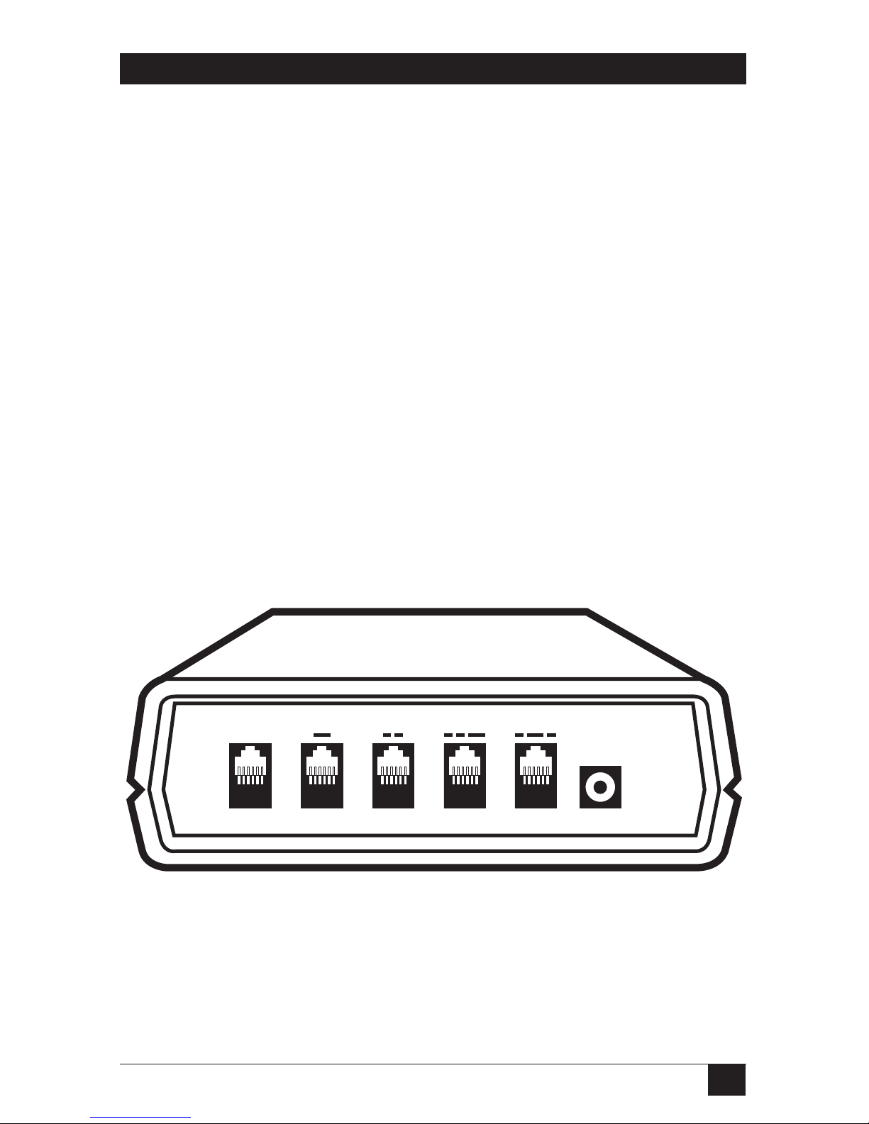
2.2 Ports on the DRD-4
The rear panel of the DRD-4 includes
five modular ports and a power input
port, as shown in Fig. 2-1.
2.1 General
The DRD-4 deciphers the
“Distinctive Ringing Service”
provided by the telephone company.
This service uses a single phone line
for multiple phone numbers and
assigns a unique ring identity to each
number. Working with this service,
the DRD-4 identifes and directs each
of the four ring types to a designated
telephone device. You can connect
up to four different telephone
devices to a single telephone line,
giving you automatic operation and
eliminiating the need to flip switches
and turn machines on or off.
TEL LINE-IN
STYLE 1 STYLE 2 STYLE 3 STYLE 4
12 VAC
Fig. 2-1. Rear View of the DRD-4.
Page 6

6
DRD-4DRD-4
STYLE 4 port—This port rings with
a short-long-short ring cadence. Use
this port for any telephone device
that you wish to respond to the
the phone company.
• The DRD-4 recognizes each ring
cadence and automatically
directs each call to its intended
destination.
• The DRD-4 allows any phone
directly connected to the unit to
answer all phone calls during the
ring signal. Once you answer a
call, the DRD-4 will not allow any
of its ports to interrupt a call to
another port. This feature
ensures your privacy during
phone calls and guarantees data
integrity when you use data
equipment.
NOTE: Only the phones connected to a port
will ring when calls are directed to
that port, but you can answer those
calls from other phones.
STYLE 4
fourth phone number.
Fig. 2-6. Style 4 Port.
NOTE: The dashed lines above each port
correspond to the port’s unique ring
cadence.
2.3 Functions of the DRD-4
The DRD-4 is compatible with any
type of telephone device that
responds to a standard phonecompany ring signal. It functions as
follows:
• The DRD-4 monitors the
telephone line for the four
distinctive ring cadences from
Page 7

7
DRD-4
Fig. 2-3. Style 1 Port.
CHAPTER 2: Introduction
Connect your telephone equipment
to the modular ports, as follows:
TEL LINE-IN port—The incoming
telephone line plugs into this port.
STYLE 2 port—This port rings with
a short-short ring cadence. Use this
port for any telephone device that
you wish to respond to the second
phone number.
TEL LINE-IN
Fig. 2-2. Tel Line-In Port.
STYLE 1 port—This port rings with
a standard phone company ring
signal. Use this port for any
telephone device that you wish to
respond to the primary phone
number.
STYLE 1
STYLE 2
Fig. 2-4. Style 2 Port.
STYLE 3 port—This port rings with
a short-short-long ring cadence. Use
this port for any telephone device
that you wish to respond to the third
phone number.
STYLE 3
Fig. 2-5. Style 3 Port.
Page 8

8
DRD-4
3. Installing the DRD-4
To install the DRD-4, you will need
the telephone cable (included) and
an additional cable for each device
you wish to connect to the DRD-4.
If the equipment you wish to
connect to the DRD-4 is not located
near the unit, you may need
extension cables.
3.1 Installing the DRD-4 on a Single
Line
Fig. 2 shows the DRD-4 installed on
a single telephone line.
You can install the DRD-4 on any
system with single- or two-line
phones, including key service unit
(KSU) or private branch exchange
(PBX) multiple-line phone systems.
This chapter explains how to install
the DRD-4 in four different phone
configurations:
• A single line
• A single line that maintains
exclusion
• Two lines with single-line and
two-line phones (with the DRD4 connected to one extension)
• A KSU/PBX system
Page 9

9
CHAPTER 3: Installing the DRD-4
To install the DRD-4 on a single line,
follow these steps:
1. Plug the small end of the AC
power cord provided with your
unit into the plug labeled
“12VAC” on the back of the
DRD-4.
2. Plug the AC adapter into any
standard 110-volt outlet. The
green indicator lights on the
front of the unit momentarily
flash on and off in a self-test
pattern. The lights then remain
off.
3. Plug one end of the telephone
cable provided with the DRD-4
into the TEL LINE-IN port on
the back of the unit.
4. Plug the other end of the
telephone cable into the wall
jack.
5. Connect your telephone
equipment to the ports
corresponding to the
appropriate telephone numbers.
EXTENSION PHONES
TEL
LINE-IN
STYLE 1
STYLE 2
STYLE 3
STYLE 4
PHONE
PHONE LINE
Fig. 3-1. Installing the DRD-4 on a Single Telephone Line.
Page 10

10
DRD-4
NOTE: With the installation shown in Fig. 3-
1, calls will only be routed to phones
connected directly to the DRD-4.
Phones not connected directly to
the DRD-4 will ring with each ring
cadence and will be able to interrupt
any call. For total automatic
operation and protect against
interruption, install the DRD-4 as
shown in Figure 3-2.
3.2 Installing the DRD-4 on a Single
Line with Multiple Phones and
Maintaining Exclusion
When you connect the DRD-4 to a
single line with multiple phones, you
may want to maintain exclusion.
Exclusion means that if one phone
line is in use and you pick up a
phone on another line. the first
phone line is not interrupted and
you get a busy signal. To maintain
exclusion, the incoming phone line
must terminate at the DRD-4, and all
phones must connect to the DRD-4
ports. See Fig. 3-2.
NOTE: You should be familiar with
telephone wiring to complete this
installation. Call Technical Support
for instructions or contact a
professionai installer.
Page 11

11
CHAPTER 3: Installing the DRD-4
3.3 Installing the DRD-4 on Two
Lines with Single-Line and Two-Line
Phones (with the DRD-4 connected
to one extension)
This arrangement typically occurs in
homes with a primary line
(residence number) and a private
business line (home business
number). Both lines may be
accessible by any number of
extension phones.
NOTE: If you have two lines but only one
phone can access line two (the
business line), use the single-line
Installation procedure described
Section 3.1. If you have two lines
and a two-line phone, use the
Installation procedure described in
this section.
For this procedure, you will need
two three-way adapters, which you
can purchase from any telephone or
electronic equipment dealer. See
Fig. 3-3 for a close-up of the threeway adapter. See Fig. 3-4 for an
illustration of the installation.
EXTENSION PHONES
TEL
LINE-IN
STYLE 1
STYLE 2
STYLE 3
STYLE 4
OLDOLD
NEW
Fig. 3-2. Installing the DRD-4 on a Single-Line, Multiple-Phone System
Maintaining Exclusion.
L1 L2
L1+L2
Fig. 3-3. A Three-Way Phone
Adapter.
Page 12

12
DRD-4
1. Plug one three-way adapter into
the wall jack.
2. Plug the other three-way adapter
into the two-line telephone jack
labeled “L1+L2.”
3. Plug one end of a phone cable
into the L1 port on one of the
three-way adapters. Plug the
other end of the cable into the
L1 port on the other three-way
adapter.
4. Plug a phone cable into the L2
port on the wall mounted threeway adapter. Plug the other end
of the cable into the TEL LINEIN port on the rear of the DRD-
4.
5. Plug a phone cable into the
STYLE 1 port on the rear of the
DRD-4. Plug the other end of
the cable into the L2 port on the
three-way adapter on the
telephone.
6. Connect the rest of your
equipment to the corresponting
ports.
Page 13

13
CHAPTER 3: Installing the DRD-4
Fig. 3-4. Installing the DRD-4 with a Two-Line Phone Using Three-Way
Adapters.
3-WAY ADAPTER
L1 L2 L1+L2
TEL
LINE-IN
STYLE 1
STYLE 2
STYLE 3
STYLE 4
3-WAY ADAPTER
L1 L2 L1+L2
TWO-LINE TELEPHONE
Page 14

14
DRD-4
3.4 Installing the DRD-4 on a
KSU/PBX System
With a KSU/PBX (commonly used
in medium or large offices), calls
coming in over two or more lines
can be routed to any number of
extensions. A KSU typically features
call holding, music-on-hold,
conference calling, and Intercom
paglng.
Fig. 3-5 shows the DRD-4 connected
to a KSU phone system. For the
DRD-4 to operate correctly with such
a system, you must install it in front
of the KSU or PBX—directly to the
incoming phone line (the last line in
rollover). You must connect all other
devlces on that line (TAD, KSU, fax,
auxilliary device) directly to the
DRD-4.
NOTE: To complete this installation, you
must be familiar with KSU/PBX
wiring.
Page 15

15
CHAPTER 3: Installing the DRD-4
Fig. 3-5. Installing the DRD-4 on a KSU Phone System.
TEL
LINE-IN
STYLE 1
STYLE 2
STYLE 3
STYLE 4
AC OUTLET
INCOMING
LINES
1
2
3
4
KSU/PBX
Page 16

16
DRD-4
4. Using the DRD-4
• Fax machines
• Order-taking systems
• Bulletin-board systems
You can use different phone
numbers to direct calls to particular
people or departments.
• Family members
• Roommates
• Departments in your business
You may also distribute different
phone numbers to different
contacts:
• Vendors
• Distributors
• Different geographic locations
NOTE: Call-waiting signals may disrupt fax
or computer transmissions.
The DRD-4 cannot process any calls
received on a line for which call
forwarding has been activated.
You can connect the DRD-4 to any
four telephone devices. The DRD-4
will automatically direct all incoming
calls to their intended destinations.
If you are using any data devices,
such as a fax or a computer, set the
devices to answer on the second or
third rlng.
You can make outbound calls from
any port on the DRD-4. Once you
take a phone off the hook, the DRD4 blocks other ports from
interrupting the initial call.
Therefore, you must directly dial any
calls placed from data equipment,
such as a fax or a computer, from
the equipment itself or from a
phone connected directly to it.
DRD-4 applications are unlimited.
Following are examples of ways in
which calls can be directed.
The DRD-4 can direct incoming calls
to any of the following types of
devices, with each device answering
calls to a different phone number:
• Home or office telephones
• Call forwarders
• Answering devices in your home
or office
• Voice mail
• Home or office computers
Page 17

Table 5-1. Troubleshooting Chart.
Problem Solution
When I pick up a Connect the DRD-4 as shown in Section 3.2.
phone, I interrupt
another call.
One of my telephone 1. Check all wiring connections.
devices won’t respond 2. Set the telephone device to its proper auto-answer
to the DRD-4. settings.
3. Plug the device directly into the telephone
extension outlet and check for a response with the
same phone number.
4. Replace the device with another device to confirm
response.
5. Call Technical Support for more assistance.
There is no dial tone, 1. Check the connection between the telephone
and no LEDs are lit. device and the DRD-4.
2. Check the AC power connection.
There is no dial tone, Check the connection between the DRD-4 and the
and one LED is lit. phone company.
17
CHAPTER 5: Troubleshooting
5. Troubleshooting
Page 18

1000 Park Drive • Lawrence, PA 15055-1018 • 724-746-5500 • Fax 724-746-0746
© Copyright 1992. Black Box Corporation. All rights reserved.
 Loading...