

Page 1
DCX3000
DCX3000 Switch
Share multiple computers with numerous users via
standard structured cabling.
Customer
Support
Information
Order toll-free in the U.S.: Call 877-877-BBOX (outside U.S. call 724-746-5500)
FREE technical support 24 hours a day, 7 days a week: Call 724-746-5500 or fax 724-746-0746
www.blackbox.com • info@blackbox.com
Page 2

DCX3000 Switch
Trademarks Used in this Manual
Black Box and the Double Diamond logo are registered trademarks, and ServSwitch is a trademark, of BB Technologies, Inc.
Mac is a registered trademark of Apple Computer, Inc.
Linux is registered trademark of Linus Torvalds.
Windows is a registered trademark of Microsoft Corporation.
NetWare is a registered trademark of Novell, Inc.
Sun is a trademark of Sun Microsystems, Inc.
Unix is a registered trademark of UNIX System Laboratories, Inc.
BSD is a registered trademark of UUNet Technologies, Inc.
Any other trademarks mentioned in this manual are acknowledged to be the property of the trademark owners.
We‘re here to help! If you have any questions about your application
or our products, contact Black Box Tech Support at 724-746 -5500
or go to blackbox.com and click on “Talk to Black Box.”
You’ll be live with one of our technical experts in less than 60 seconds.
Page 2
724-746-5500 | blackbox.com
Page 3

FCC and IC RFI Statements
Federal Communications Commission and Industry Canada Radio Frequency Interference
Statements
This equipment generates, uses, and can radiate radio-frequency energy, and if not installed and used properly, that is, in strict
accordance with the manufacturer’s instructions, may cause inter ference to radio communication. It has been tested and found to
comply with the limits for a Class A computing device in accordance with the specifications in Subpart B of Part 15 of FCC rules,
which are designed to provide reasonable protection against such interference when the equipment is operated in a commercial
environment. Operation of this equipment in a residential area is likely to cause interference, in which case the user at his own
expense will be required to take whatever measures may be necessary to correct the interference.
Changes or modifications not expressly approved by the party responsible for compliance could void the user’s authority to
operate the equipment.
This digital apparatus does not exceed the Class A limits for radio noise emis sion from digital apparatus set out in the Radio
Interference Regulation of Industry Canada.
Le présent appareil numérique n’émet pas de bruits radioélectriques dépassant les limites applicables aux appareils numériques de
la classe A prescrites dans le Règlement sur le brouillage radioélectrique publié par Industrie Canada.
724-746-5500 | blackbox.com
Page 3
Page 4

DCX3000 Switch
Instrucciones de Seguridad
(Normas Oficiales Mexicanas Electrical Safety Statement)
1. Todas las instrucciones de seguridad y operación deberán ser leídas antes de que el aparato eléctrico sea operado.
2. Las instrucciones de seguridad y operación deberán ser guardadas para referencia futura.
3. Todas las advertencias en el aparato eléctrico y en sus instrucciones de operación deben ser respetadas.
4. Todas las instrucciones de operación y uso deben ser seguidas.
5. El aparato eléctrico no deberá ser usado cerca del agua—por ejemplo, cerca de la tina de baño, lavabo, sótano mojado o cerca
de una alberca, etc.
6. El aparato eléctrico debe ser usado únicamente con carritos o pedestales que sean recomendados por el fabricante.
7. El aparato eléctrico debe ser montado a la pared o al techo sólo como sea recomendado por el fabricante.
8. Servicio—El usuario no debe intentar dar servicio al equipo eléctrico más allá a lo descrito en las instrucciones de operación.
Todo otro servicio deberá ser referido a personal de servicio calificado.
9. El aparato eléctrico debe ser situado de tal manera que su posición no interfiera su uso. La colocación del aparato eléctrico
sobre una cama, sofá, alfombra o superficie similar puede bloquea la ventilación, no se debe colocar en libreros o gabinetes
que impidan el flujo de aire por los orificios de ventilación.
10. El equipo eléctrico deber ser situado fuera del alcance de fuentes de calor como radiadores, registros de calor, estufas u otros
aparatos (incluyendo amplificadores) que producen calor.
11. El aparato eléctrico deberá ser connectado a una fuente de poder sólo del tipo descrito en el instructivo de operación, o como
se indique en el aparato.
12. Precaución debe ser tomada de tal manera que la tierra fisica y la polarización del equipo no sea eliminada.
13. Los cables de la fuente de poder deben ser guiados de tal manera que no sean pisados ni pellizcados por objetos colocados
sobre o contra ellos, poniendo particular atención a los contactos y receptáculos donde salen del aparato.
14. El equipo eléctrico debe ser limpiado únicamente de acuerdo a las recomendaciones del fabricante.
15. En caso de existir, una antena externa deberá ser localizada lejos de las lineas de energia.
16. El cable de corriente deberá ser desconectado del cuando el equipo no sea usado por un largo periodo de tiempo.
17. Cuidado debe ser tomado de tal manera que objectos liquidos no sean derramados sobre la cubierta u orificios de ventilación.
18. Servicio por personal calificado deberá ser provisto cuando:
A: El cable de poder o el contacto ha sido dañado; u
B: Objectos han caído o líquido ha sido derramado dentro del aparato; o
C: El aparato ha sido expuesto a la lluvia; o
D: El aparato parece no operar normalmente o muestra un cambio en su desempeño; o
E: El aparato ha sido tirado o su cubierta ha sido dañada.
Page 4
724-746-5500 | blackbox.com
Page 5

Table of Contents
Contents
1. Specifications .............................................................................................................................................................................. 6
2. Welcome .................................................................................................................................................................................... 7
2.1 Access permissions ............................................................................................................................................................ 7
2.2 Port designations .............................................................................................................................................................. 8
3. Installation .................................................................................................................................................................................. 9
3.1 Connections ...................................................................................................................................................................... 9
3.1.1 Computer connections: Video .............................................................................................................................. 9
3.1.2 Computer connections: USB ............................................................................................................................... 10
3.1.3 Computer connections: Data link ....................................................................................................................... 10
3.1.4 Switch connections: Computer links ....................................................................................................................11
3.1.5 Reallocating ports ................................................................................................................................................ 11
3.1.6 Switch connections: User console links ................................................................................................................11
3.1.7 Switch connections: Network link ........................................................................................................................12
3.1.8 Switch connections: Serial options port ...............................................................................................................12
3.1.9 Switch connections: Power ..................................................................................................................................13
3.1.10 Console connections: Video .............................................................................................................................. 14
3.1.11 Console connections: USB ..................................................................................................................................15
3.1.12 Console connections: Audio ..............................................................................................................................15
3.1.13 Console connections: Data link ......................................................................................................................... 16
3.1.14 Console connections: Options port ................................................................................................................... 16
3.1.15 Console connections: Power ..............................................................................................................................17
4. Configuration ........................................................................................................................................................................... 18
4.1. Accessing DCX Matrix .................................................................................................................................................... 18
4.2 Using DCX Matrix ........................................................................................................................................................... 20
4.3 Quick guide to creating a new installation ...................................................................................................................... 21
4.4 The Control page ............................................................................................................................................................ 22
4.5 The Configure pages ...................................................................................................................................................... 23
4.6 Configure > Consoles ..................................................................................................................................................... 26
4.7 Configure > Consoles > Receivers ................................................................................................................................... 28
4.8 Configure > Computers .................................................................................................................................................. 30
4.9 Configure > Computers > Transmitters ........................................................................................................................... 32
4.10 Reallocating ports ......................................................................................................................................................... 34
4.11 The Users page.............................................................................................................................................................. 35
4.12 The Maintenance pages ................................................................................................................................................ 36
4.13 Resetting and recovering .............................................................................................................................................. 39
5. Operation ..................................................................................................................................................................................41
5.1 Viewing the OSD .............................................................................................................................................................41
5.2 Choosing a computer ......................................................................................................................................................41
5.3 Indicators ........................................................................................................................................................................ 42
Appendix A. Safety Information ................................................................................................................................................... 44
724-746-5500 | blackbox.com
Page 5
Page 6

DCX3000 Switch
1. Specifications
Approvals: CE, FCC
Hardware Compatibility: All computers with DVI-D/DisplayPort digital video and USB interfaces
Software Compatibility: Operates with all known software and operating systems including
Windows®, Linux®, Unix®, BSD, all Sun® OS, all Mac® OS, NetWare®, etc.
Operating Temperature: 32 to 104°F (0 to 40°C)
Page 6
724-746-5500 | blackbox.com
Page 7
2. Welcome
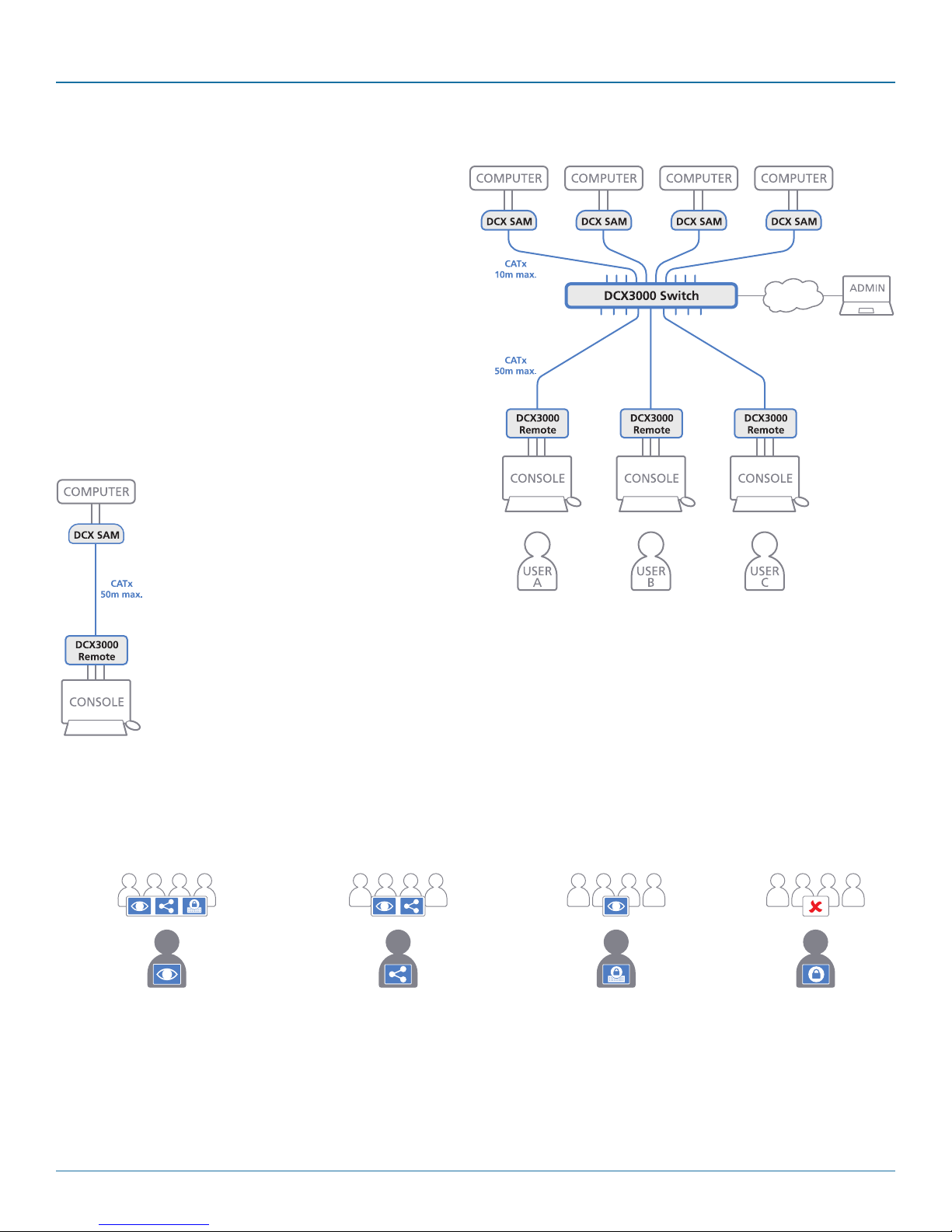
Thank you for choosing the Black Box DCX3000 system. This
adaptive system makes sharing numerous host computers
among multiple users straightforward and flexible. Every
computer is linked, via its USB and video ports, to a compact
DCX3000 SAM module while each set of peripherals are connected to a DCX3000 Remote module (to form Consoles).
The various computers and consoles are then linked, via standard CAT7 cable, to a central DCX3000 Switch. Each user
can then, subject to the privileges granted by the admin, gain
quick access to any of the required computers.
An integral part of the DCX3000 Switch is the DCX Matrix, a
browser-based configuration and management tool that
allows one or more remote admin user(s) to monitor and
maintain all aspects of operation.
Chapter 2: Overview
If required, computers and consoles can be individually connected in order to take advantage of
the DCX3000 extender properties
without the switching.
2.1 Access permissions
The DCX3000 Switch uses a system of hierarchal Access permissions to mediate between numerous consoles and multiple computers. Each console is granted the use of up to four types of access permissions to each computer, most of which influence how
other users can gain simultaneous access to the same computer. The four access permissions, and their effects on other console
users are as follows:
VIEW ONLY
The console user can view the chosen
computer’s output but cannot alter it.
Once selected, other consoles can
simultaneously use
VIEW ONLY,
SHARED ACCESS or EXCLUSIVE
for the same computer.
Note: The hierarchy of permissions shown here increases from left to right.
The console user can view and control
the chosen computer’s output.
Once selected, other consoles can
SHARED ACCESS
simultaneously use
VIEW ONLY or
SHARED ACCESS
for the same computer.
The console user can view and
control the chosen computer’s
Once selected, other consoles can
EXCLUSIVE
output.
simultaneously use
VIEW ONLY
for the same computer.
724-746-5500 | blackbox.com
PRIVATE
The console user can view
and control the chosen
computer’s
output.
Once selected, all other
consoles are completely
locked out from the same
computer.
Page 7
Page 8
DCX3000 Switch
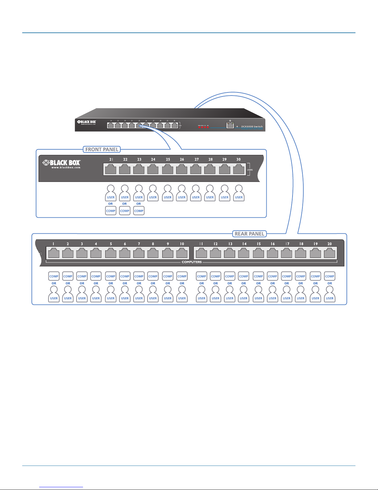
2.2 Port designations
By default the DCX3000 Switch provides 10 user console ports on its front panel and 20 computer ports along its rear panel,
however, these designations are not fixed. If your installation requires a greater number of computers or has a need for more user
consoles, you can alter the allocation of these standard ports to suit:
Ports 21 to 23 can
be reallocated as
computer ports.
Any of the 20 rear panel computer ports can be reallocated as user console ports
Page 8
724-746-5500 | blackbox.com
Page 9
Chapter 3: Installation
3. Installation
Please consider the following important points when planning the position of the DCX3000 modules:
• If used, position the DCX3000 Switch in a central position that serves the host systems and user modules without exceeding
the maximum link lengths. It will also require a source of mains power.
• Situate each DCX3000 Remote module close to the peripherals to which it will be connected and near to a source of mains
power.
• Consult the precautions listed within the Safety information section.
3.1 Connections
Connections do not need to be carried out in the order given within this guide, however, where possible connect the power in as
a final step. Connections are split into the following three areas:
• Computer connections - a DCX3000 SAM module links to each computer.
• Switch connections - when used, a DCX3000 Switch unit sits at the heart of the system.
• Console connections - the peripherals (keyboard, display, etc.) connect to DCX3000 Remote modules.
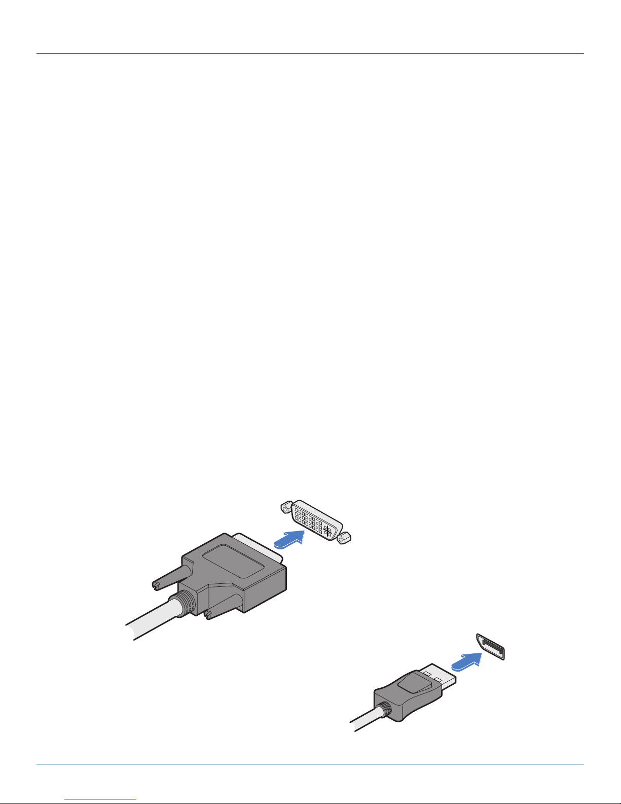
3.1.1 Computer connections: Video
Two types of DCX3000 SAM modules are available:
• DVI-D and USB,
or
• DisplayPort and USB.
If a computer has more than one video output, use additional DCX3000 SAM modules to separately link the alternative video
stream(s) with other ports on the DCX3000 Switch.
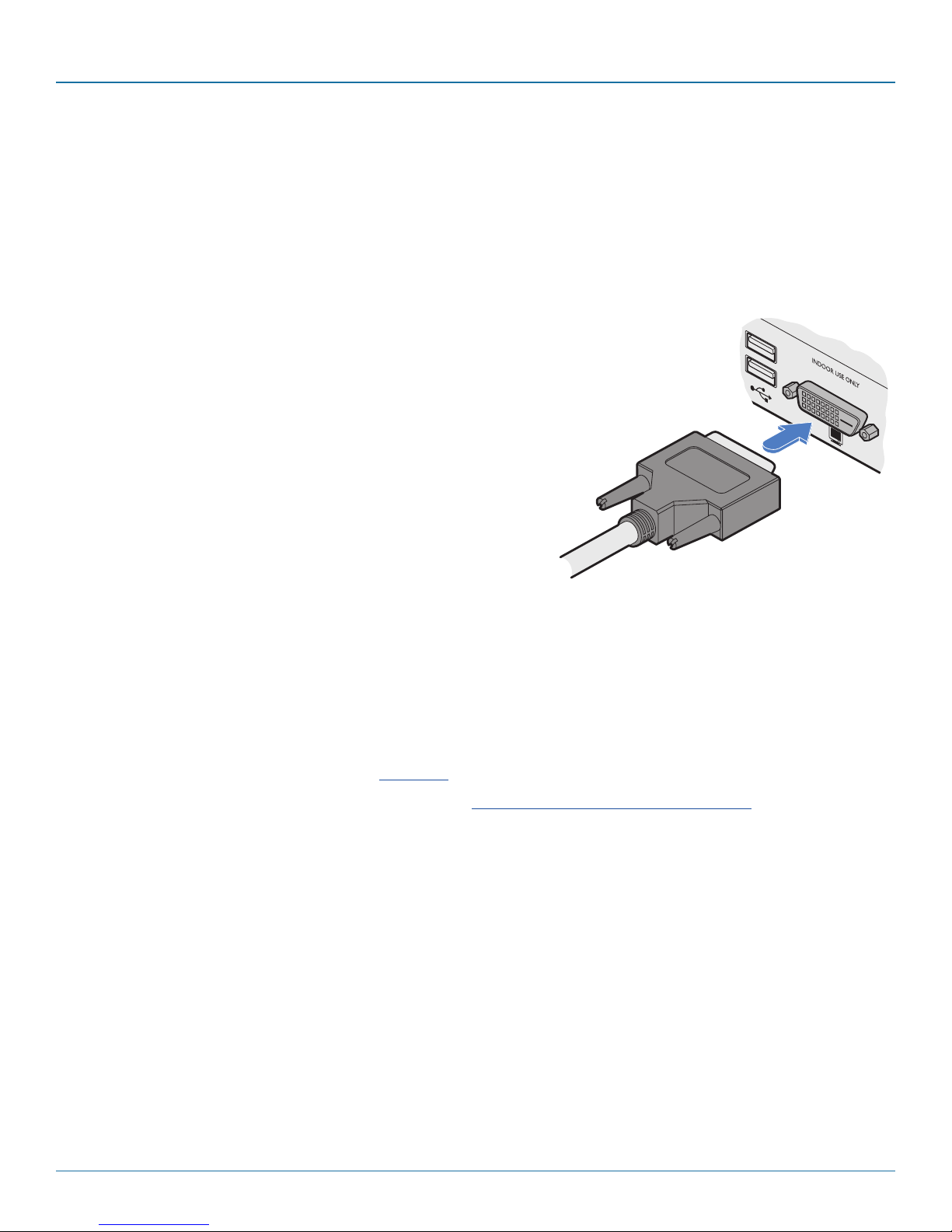
3.1.1.1 To connect the video port
1 Connect the video lead of the DCX3000 SAM to the DVI-D or DisplayPort video port of the host computer.
DVD-D video port on
the host computer
DVI-D video lead
from the
DCX3000 SAM
OR
DisplayPort on the
host computer
DisplayPort video
lead from the
DCX3000 SAM
724-746-5500 | blackbox.com
Page 9
Page 10
DCX3000 Switch
3.1.2 Computer connections: USB
Each DCX3000 SAM module requires a single USB connection to the computer. This provides essential power for the DCX3000
SAM module in addition to the USB signals. Each DCX3000 Remote module acts as a USB 2.0 hub and thus provides four sockets
for peripherals.
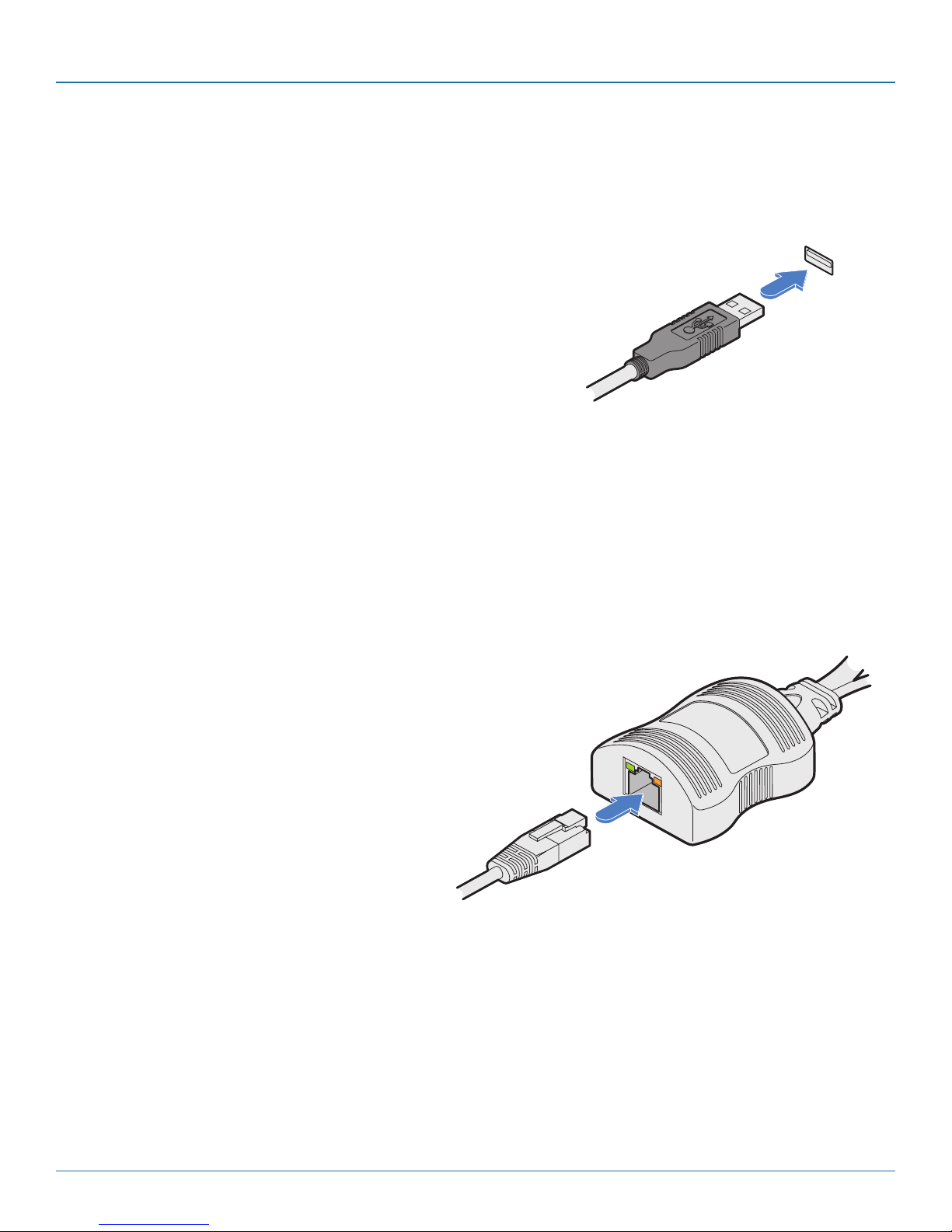
3.1.2.1 To connect the USB port
1 Connect the USB cable of the DCX3000 SAM module to a vacant USB socket
on your host computer.
USB lead from the
DCX3000 SAM
3.1.3 Computer connections: Data link
Each DCX3000 SAM module is linked via a CATx cable either to a central DCX3000 Switch module (multi-system matrix installation) or directly to a DCX3000 Remote module (single system installation).
For best results use CAT7 cables to link all DCX3000 SAM modules. Maximum cable lengths:
• DCX3000 SAM to DCX3000 Switch - 32 feet (10m) maximum.
• DCX3000 SAM to DCX3000 Remote - 164 feet (50m) maximum.
3.1.2.2 To link the DCX3000 SAM module
1 Connect the RJ-45 plug of the link cable to the socket located at the end of the
DCX3000 SAM module.
CATx link from
DCX3000 Switch
or DCX3000
Remote module
Page 10
724-746-5500 | blackbox.com
Page 11
Chapter 3: Installation
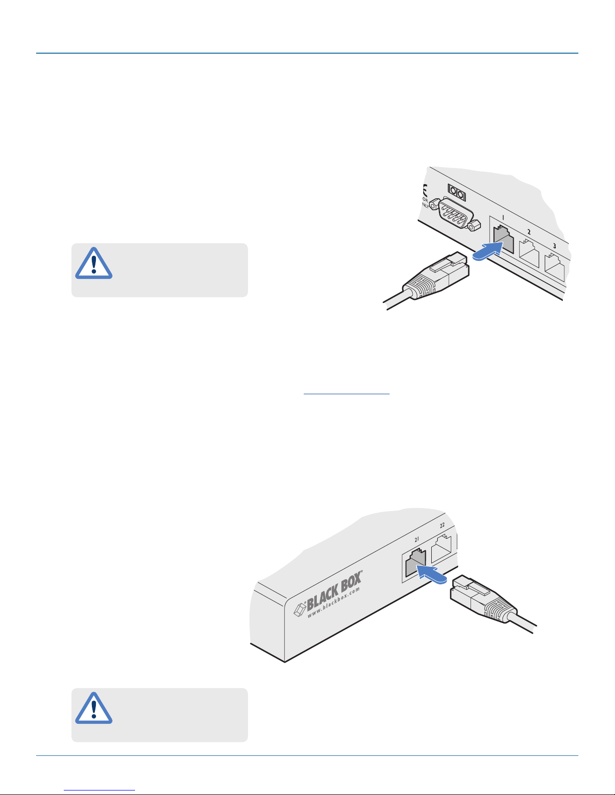
3.1.4 Switch connections: Computer links
When a DCX3000 Switch is used, it sits as the central matrix between the various host computers and the users. The host computer links are generally made via the sockets at the rear of the switch, although some host links can also be supported from the
sockets on the front panel (see below).
3.1.4.1 To connect a host link
1 Connect the CAT7 cable from the remote DCX3000 SAM host module to a
vacant RJ-45 socket on the rear panel of the DCX3000 Switch.
These are NOT Ethernet/network
ports and must NEVER be
connected to any networking
equipment.
From a remote DCX3000
SAM host module
3.1.5 Reallocating ports
By default the DCX3000 Switch provides 20 computer ports along its rear panel and 10 user ports along its front panel. If
necessary, these standard arrangements can be changed. See Reallocating ports.
3.1.6 Switch connections: User console links
The user data links are generally made via the sockets at the front of the switch, although any of the rear panel sockets can also
be converted to user ports (see above).
3.1.6.1 To connect a console link
1 Connect the CAT7 cable from the remote
DCX3000 Remote module to a vacant RJ-45
socket on the front panel of the DCX3000
Switch.
From a DCX3000
remote module
These are NOT Ethernet/network
ports and must NEVER be
connected to any networking
equipment.
724-746-5500 | blackbox.com
Pa ge 11
Page 12
DCX3000 Switch
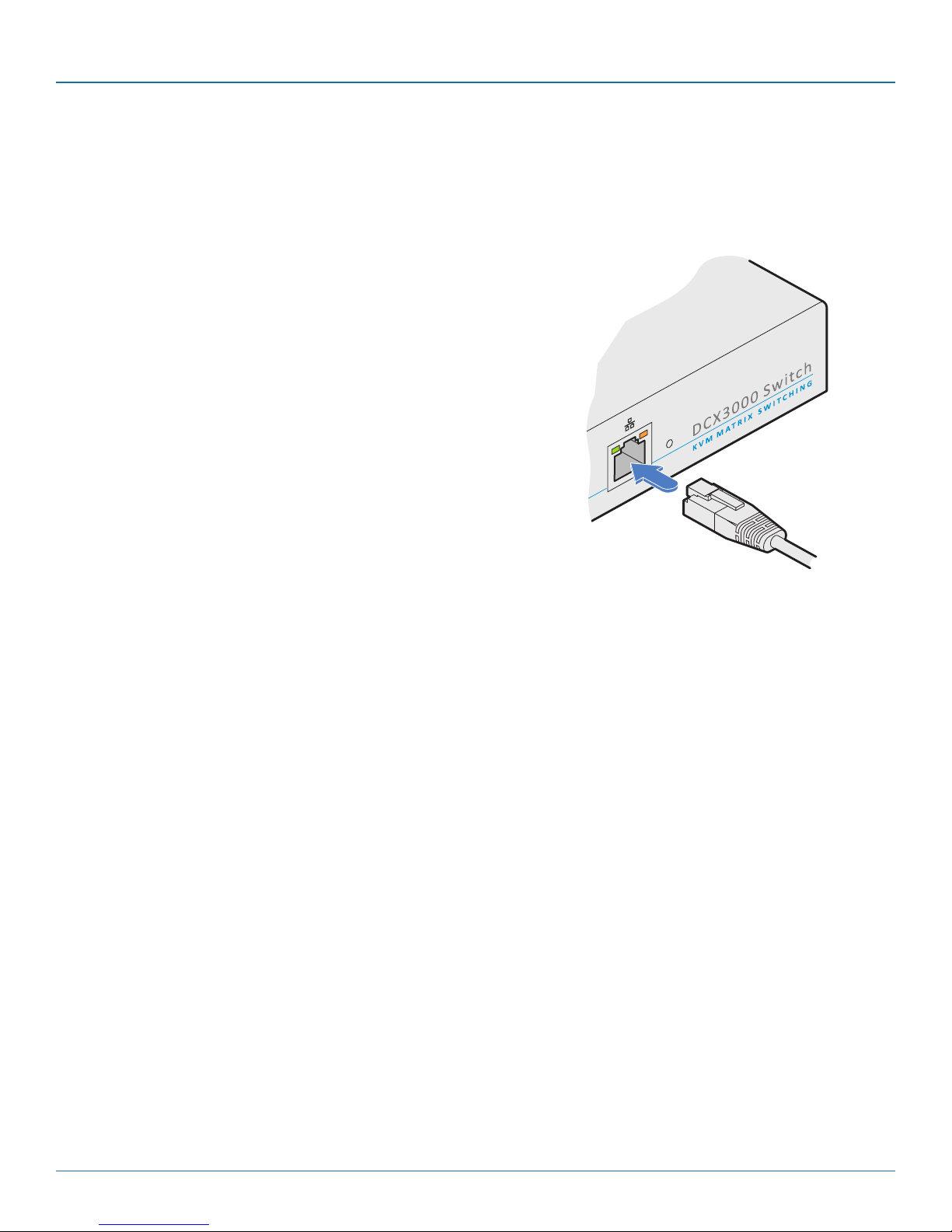
3.1.7 Switch connections: Network link
All system configuration is carried out via an Ethernet link, allowing adjustments to be made by authorized admin users located
next to the DCX3000 unit, or anywhere. The auto-sensing network port can determine between 10, 100Mbps or 1Gbps links
and can also adjust to straight or cross-over cables.
3.1.7.1 To connect a network link
1 Connect the CATx cable from the nearest Ethernet switch or from a local computer.
3.1.8 Switch connections: Serial options port
The options port is reserved for future use.
From a network switch or
nearby computer
Page 12
724-746-5500 | blackbox.com
Page 13
Chapter 3: Installation
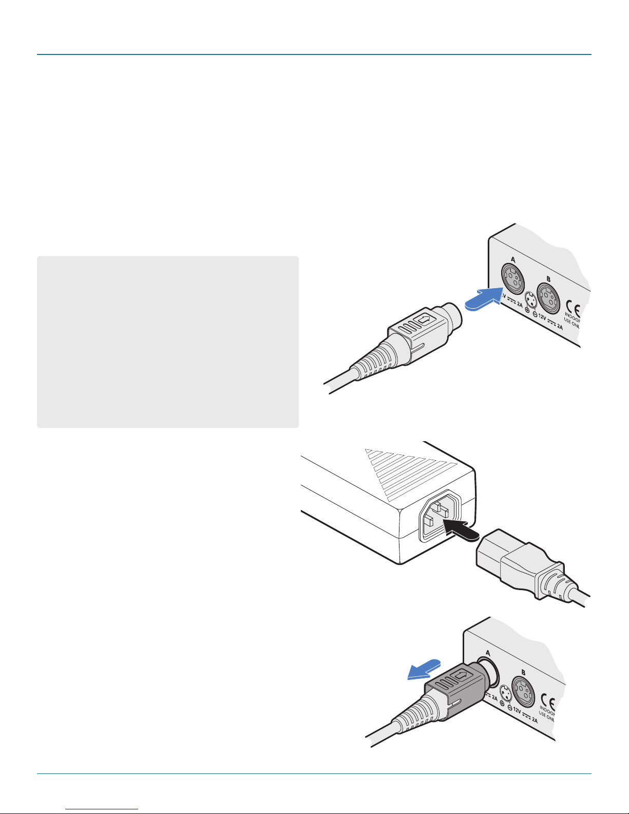
3.1.9 Switch connections: Power
Each DCX3000 Switch is supplied with a single power adapter but offers the facility to use a second input in order to provide
operational redundancy. The DCX3000 unit can operate perfectly well from a single power adapter operating alone. When two
adapters are connected, the unit will spread its load between them; should one power input fail, 100% of the load will be transferred to the other power adapter without a break in operation. Remote checking of the power inputs is possible at any time via
the Maintenance page of the browser interface.
There is no on/off switch on the DCX3000 unit, so operation begins as soon as power is applied at either port.
3.1.9.1 To connect the power adapter
1 Attach the output plug of the supplied power adapter to either power input socket on the left
side of the rear panel.
IMPORTANT: Please read and adhere to the electrical safety
information given within the Safety information section of
this guide. In particular, do not use an unearthed power
socket or extension cable.
Note: Both the modules and the power supplies generate
heat when in operation and will become warm to the
touch. Do not enclose them or place them in locations
where air cannot circulate to cool the equipment. Do not
operate the equipment in ambient temperatures exceeding
40 degrees Centigrade. Do not place the products in contact with equipment whose surface temperature exceeds
40 degrees Centigrade.
From the
power adapter
2 Connect the IEC connector of the supplied country-
specific power cord to the socket of the power adapter.
3 Connect the power cord to a nearby main supply socket.
4 Where power redundancy is required, repeat steps 1 to
3 for a second power adapter.
3.1.9.2 To disconnect the power adapter
1 Isolate the power adapter from the mains supply.
Note: If you are replacing one of dual power adapters during opera-
tion, it is not necessary to also remove power from the other adapter.
2 Grasp the outer body of the power adapter plug where it connects
with the module.
3 Gently pull the body of the outer plug away from the module. As the
body of the plug slides back, it will release from the socket and you
can fully withdraw the whole plug.
Gently pull back the plug outer
body to release the lock
724-746-5500 | blackbox.com
Page 13
Page 14
DCX3000 Switch
3.1.10 Console connections: Video
A Single Link DVI-D port is provided on the rear panel of the user module.
The DCX3000 Remote module supports one video display with pixel clocks up to 165MHz (equivalent to a maximum resolution
of 1920 x 1200 at 60Hz - aka ‘WUXGA’).
If a second display is required to support a dual video installation, use another DCX3000 Remote module to drive the second display, and combine the two user modules into a single Console within the DCX Matrix configuration application.
3.1.10.1 To connect the video display
1 Connect the DVI-D video cable from your video display to the video output port on the rear
panel of the user module.
From your
video display
3.1.10.2 EDID management
The DCX3000 Switch provides a number of fixed EDID (Extended Display Identification Data) profiles that will suit a large number
of video display configurations. If additional EDID definitions are required for your installation, you can clone new definitions from
connected video displays and add these to the list of available definitions.
For details about cloning EDIDs from displays, see Add EDID.
For details about applying an EDID to a particular computer, see Configure > Computers > Transmitters.
3.1.10.3 DCX3000 Remote module switches
The two switches on the DCX3000 Remote module are reserved for future use and must both remain in the OFF position.
Page 14
724-746-5500 | blackbox.com
Page 15

Chapter 3: Installation
3.1.11 Console connections: USB
The DCX3000 Remote module contains a USB hub that can support up to four v1.1 or v2.0 USB devices (in any combination). All
four USB sockets, two on the front panel and two on the rear, are identical in operation.
Note: In multi-head installations, the USB devices must be attached only to the DCX3000 Remote that drives the main display.
3.1.11.1 To connec t USB devices
1 Connect your USB keyboard and mouse to any of the four sockets distributed on the front and rear panels of the user module.
Rear panel
From USB
devices
Front panel
3.1.12 Console connections: Audio
The DCX3000 Remote module supports stereo speakers, headphones and also a microphone
port. All audio devices are presented at the linked host computer as USB audio devices.
Note: In multi-head installations, the audio devices must be attached only to the DCX3000
Remote that drives the main display.
3.1.12.1 To connect your speakers
1 Connect your speakers to the audio line out socket on the user module rear panel.
From your speakers
3.1.12.2 To connect your headphones/
microphone
1 Connect your headphones to the socket
labeled on the user module front panel.
2 Connect your microphone to the socket labeled
on the user module front panel.
From USB
devices
724-746-5500 | blackbox.com
From your microphone
From your headphones
Page 15
Page 16
DCX3000 Switch
3.1.13 Console connections: Data link
Each DCX3000 Remote module is linked via a CATx cable either to a central DCX3000 Switch module (multi-system matrix installation) or directly to a DCX3000 SAM module (single system installation).
For best results use CAT7 cables to link all DCX3000 SAM modules - do not exceed 50 meters (164 feet).
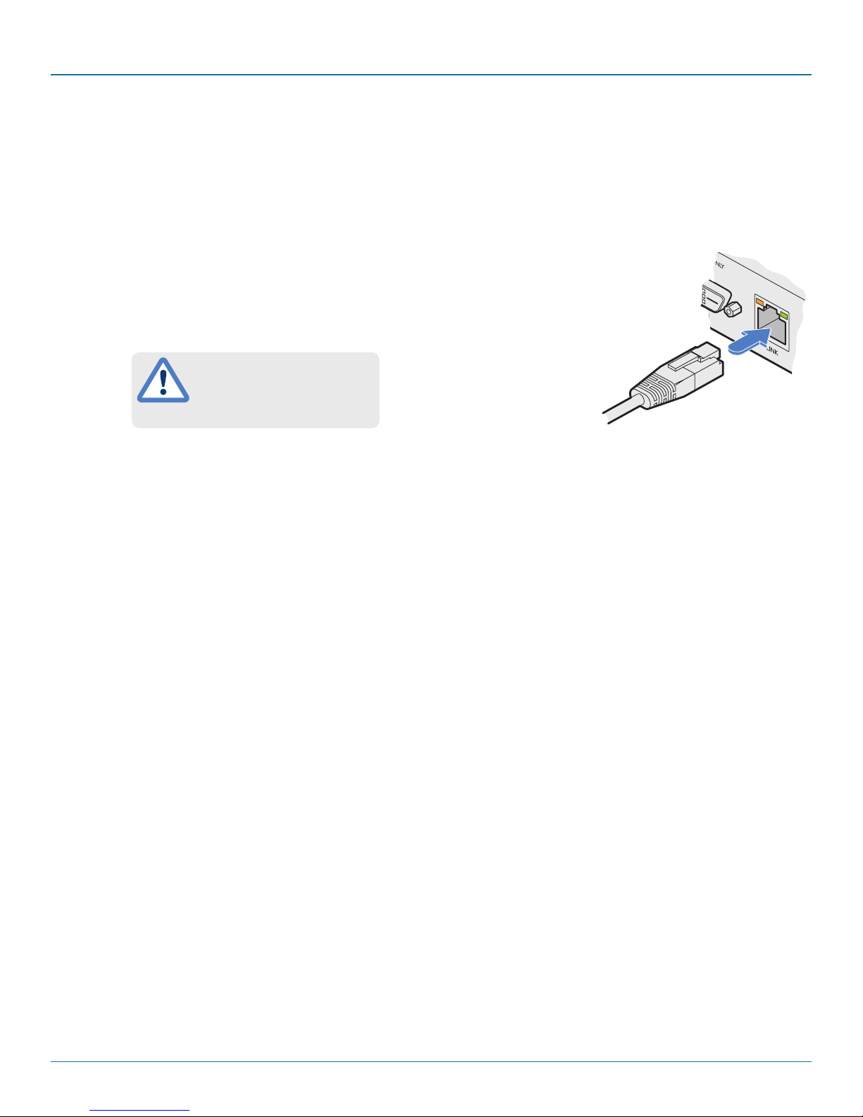
3.1.13.1 To link the DCX3000 Remote module
1 Connect a suitable CATx cable to the LINK socket on the rear panel of the DCX3000 Remote
module. Connect the other end of the cable to either a DCX3000 Switch or directly to a
DCX3000 SAM host module.
This is NOT an Ethernet/network
port and must NEVER be
connected to any networking
equipment.
From DCX3000
Switch or DCX3000
SAM
3.1.14 Console connections: Options port
The options port is reserved for future use.
Page 16
724-746-5500 | blackbox.com
Page 17

Chapter 3: Installation
3.1.15 Console connections: Power
There is no on/off switch on the DCX3000 Remote module, so operation begins as soon as power is applied. The supplied power
adapter uses a locking-type plug to help prevent accidental disconnections; please follow the instructions given right whenever
disconnecting a power adapter.
3.1.15.1 To connect the power adapter
1 Attach the output plug of the supplied power adapter to either power input socket on the rear panel of the DCX3000
Remote module.
IMPORTANT: Please read and adhere to the electrical safety
information given within the Safety information section of
this guide. In particular, do not use an unearthed power
socket or extension cable.
Note: Both the modules and the power supplies generate
heat when in operation and will become warm to the
touch. Do not enclose them or place them in locations
where air cannot circulate to cool the equipment. Do not
operate the equipment in ambient temperatures exceeding
40 degrees Centigrade. Do not place the products in contact with equipment whose surface temperature exceeds
40 degrees Centigrade.
From the
power adapter
2 Connect the IEC connector of the supplied country-
specific power cord to the socket of the power
adapter.
3 Connect the power cord to a nearby main supply
socket.
4 Where power redundancy is required, repeat steps 1
to 3 for a second power adapter.
3.1.15.2 To disconnect the power adapter
1 Isolate the power adapter from the mains supply.
2 Grasp the outer body of the power adapter plug where it connects
with the module.
3 Gently pull the body of the outer plug away from the module. As the
body of the plug slides back, it will release from the socket and you
can fully withdraw the whole plug.
724-746-5500 | blackbox.com
Gently pull back the plug outer
body to release the lock
Page 17
Page 18
DCX3000 Switch
4. Configuration
4.1. Accessing DCX Matrix
DCX3000 Switches are configured via their network connections using an intuitive browser-based application, called DCX Matrix.
This secure, password protected application is accessible by any authorized admin user, located anywhere.
4.1.1 To access DCX Matrix
1 Use a computer that is directly or indirectly (i.e. via a network switch) connected to the DCX3000 Switch. If you need to
make a temporary connection, see below.
2 DHCP (Dynamic Host Configuration Protocol) is enabled by default. To find the IP address of the DCX Matrix interface, open
the OSD on one of the connected user consoles.
3 If there is no DHCP on the network, after one minute a time out will occur and the default IP address https://192.168.1.22
will be used.
Note: For security, DCX Matrix uses HTTPS by default with a self-signed certificate - Please ignore any warnings that may be
displayed by your web browser.
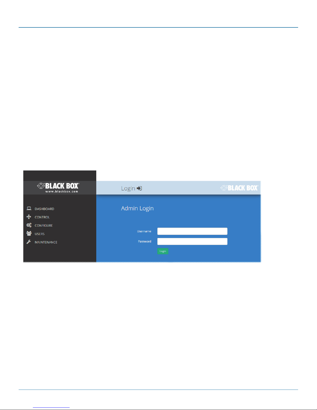
4 If requested, enter your username and password to log on. Note: The default username and password are admin and
password respectively.
The opening page of the DCX Matrix should be displayed:
Page 18
724-746-5500 | blackbox.com
Page 19
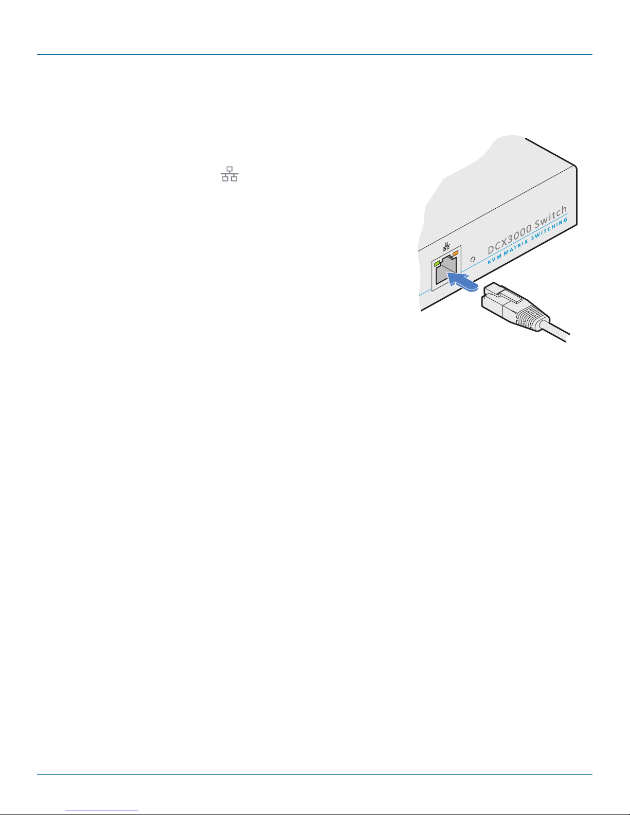
4.1.2 To temporarily connect a computer to the network port
1 If you need to make a temporary connection for configuration purposes, use a
standard patch cable (cross-over or straight connections are both supported) to
link the Ethernet 10/100 network port ( ) on the front panel of the DCX3000
Switch to your computer’s network port.
Chapter 4: Configuration
724-746-5500 | blackbox.com
Page 19
Page 20
DCX3000 Switch
4.2 Using DCX Matrix
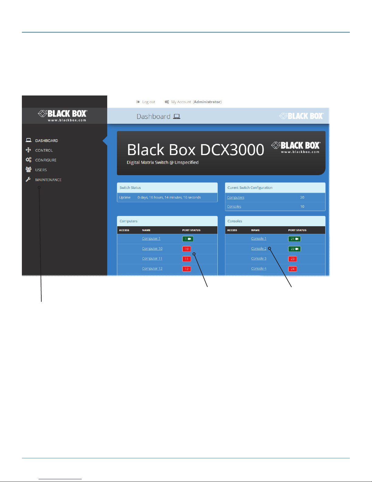
4.2.1 The Dashboard page
Once you have successfully logged in, DCX Matrix will show the dashboard page to provide a general overview of your DCX
installation. You can also re-display this page by clicking the Dashboard entry in the menu:
Colors are used to provide quick
visual feedback. Here ports shown
Click the required menu
item to reveal the available
page choices.
in green are operational while
those in red are disconnected.
Ports shown in white indicate that
their modules require a firmware
update.
Note: It is not possible to leave DCX Matrix open for more than 24 hours.
Information and options are
displayed within the main
section of the page.
Some items will provide further popup information
when you hover your
mouse pointer over them.
Page 20
724-746-5500 | blackbox.com
Page 21

Chapter 4: Configuration
4.3 Quick guide to creating a new installation
When creating a new DCX installation there are various tasks that need to be completed.
This page provides a recommended ‘to do list’ of the stages that you need to perform.
4.3.1 Primary tasks
• Configure the networking details for the DCX3000 Switch See Configure > Central Switch > Network
• Ensure that the EDID definitions are appropriate for your installation See Configure > Central Switch > Manage EDIDs
If additional EDID definitions are required for your installation,
you can clone new definitions from connected video displays
and add these to the list of available definitions See Add EDID
• Add the required consoles (either before or after they are connected) See Configure > Consoles
By default the DCX3000 Switch provides 20 computer ports along
its rear panel and 10 user ports along its front panel. If necessary,
these standard arrangements can be changed to suit your
installation See Reallocating ports
• Determine the access permissions for each console See Access permissions
• Add your computers (either before or after they are connected) See Configure > Computers
• Add the users and define their login details See The Users Page
4.3.2 Secondary tasks
• Optionally make changes to the OSD settings See Configure > Central Switch > OSD Settings
• Name the switch and add description and location details See Configure > Central Switch > General
724-746-5500 | blackbox.com
Page 21
Page 22

DCX3000 Switch
4.4 The Control page
The Control page provides
a Connection map that
allows the admin user to
view and affect how consoles are connected to the
various computers. This
page is particularly useful
when managing video-only
installations.
4.4.1 To connect a console
1 Click the down arrow on the console entry to reveal the
list of computers that it is authorized to access.
2 Click the appropriate connection icon adjacent to the
required computer:
•
•
•
or
•
For further details, see Access permissions.
3 You can change the connection method at any time by
clicking the down arrow again and choosing an alternative
connection option.
View only - console user can view a computer’s
output but not alter it,
Shared access - console user can view and
control a computer along with other consoles,
Exclusive - multiple console users can view a
computer but only one can control it,
Private - console user can view and control the
computer privately while other users are locked
out.
4.4.2 To disconnect a console
1 Click the button in the lower left corner of
the console entry that you wish to disconnect.
Page 22
724-746-5500 | blackbox.com
Page 23
Chapter 4: Configuration
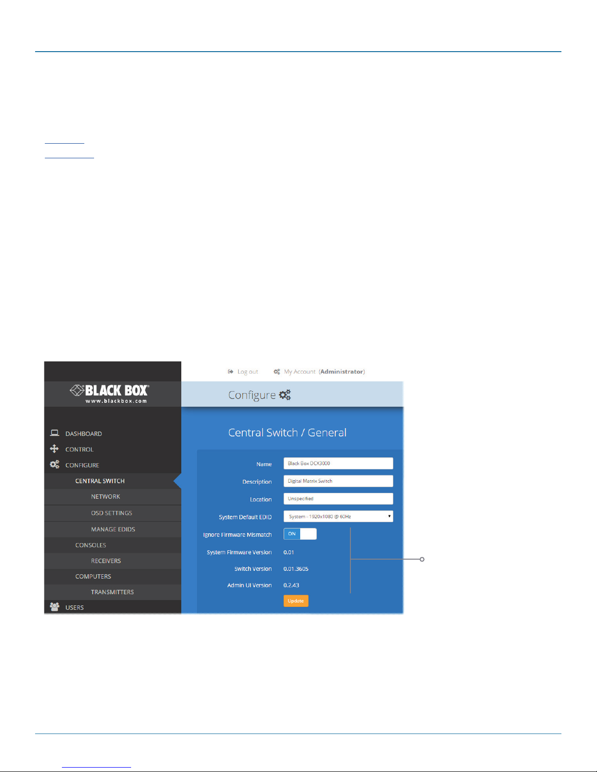
4.5 The Configure pages
The Configure menu option expands when clicked to reveal three sub-sections:
• Central Switch - settings related directly to the DCX3000 Switch.
• Consoles - settings related to the DCX3000 Remote modules and their connected peripherals.
• Computers - settings related to the DCX3000 SAM modules and their host computers.
4.5.1 Central Switch > General
Basic descriptive settings for the DCX3000 Switch. These are most useful when multiple DCX installations are being managed and
labelling each installation as you go, is a good habit to get into:
• Name - displayed on the dashboard page of DCX Matrix to identify this switch.
• Description - a further opportunity to add more information about the switch.
• Location - a useful feature if you have multiple DCX3000 Switches distributed around.
• System Default EDID - determines the default EDID to use for the installation.
• Ignore Firmware Mismatch - when set to On, this overrides the checks that are made to ensure all modules are running
compatible firmware versions. This override should be used in exceptional circumstances only.
• System Firmware Version - shows the version of the main system firmware.
• Switch Version - shows the version of the main system circuitry.
• Admin UI Version - shows the version of the DCX Matrix admin user interface.
724-746-5500 | blackbox.com
These items are
shown only when
the Maintenance
> Settings > Web
UI Mode is set to
Advanced.
Page 23
Page 24

DCX3000 Switch
4.5.2 Central Switch > Network
All of the key settings for the network capabilities of the DCX3000 Switch are here:
• DHCP - allows you to choose to use DHCP (Dynamic Host Configuration
Protocol) to automatically determine all network settings or set them
manually. When set to On, all other options in this page will be grayed out.
• IP Address - set the IP address for the switch.
• Net Mask - set a subnet mask to accompany the IP address.
• Gateway - optionally define a suitable address for a gateway device (only
needed if external access to DCX Matrix is required).
• MAC Address - displays the unique (and fixed) MAC address for the switch.
• HTTP Server - switches to the use of insecure HTTP for web admin - switch
reboot required. IMPORTANT: Do not enable this option when the
switch is connected to external networks.
4.5.3 Central Switch > OSD Settings
Options related to the on screen display are presented in this section:
• Thumbnails - when set to Off, this option will hide the thumbnail views of
each computer within each user’s OSD main page.
• Auto Layout - when set to Off, this option will maintain a 5x5 grid for the
displayed computers within the OSD main page, regardless of the number
of available computers. When set to On, the OSD view grid will be re-scaled
accordingly.
• Display System Info - when set to On, the IP address and firmware version
details for the DDX switch will be shown in the bottom corner of the OSD.
Page 24
724-746-5500 | blackbox.com
Page 25

Chapter 4: Configuration
4.5.4 Central Switch > Manage EDIDs
This page lists the EDID (Extended Display Identification Data) profiles that are currently available:
• EDID - shows the resolutions and refresh rates for all EDID
profiles that are currently stored.
• Type - indicates where each EDID profile originated: Fixed
EDIDs are included within the switch firmware and cannot
be removed. User EDIDs are those that have been cloned
from particular video displays attached to DCX3000 Remote
modules - these can be deleted if required. On the main
Central Switch/General page you can select the ‘Default
System EDID’ from the list of fixed and user EDIDs.
• Originating Port - indicates which switch port supplied each
user EDID.
Note: The DCX3000 Switch will modify the EDID, if a Dual link
monitor is connected, to list only the video resolutions that it is
capable of supporting.
4.5.4.1 Add EDID
If additional EDID definitions are required for your installation, you can clone new definitions from connected video
displays and add these to the list of available definitions.
Click the [+] icon to begin collecting a new EDID from a
display attached (via a DCX3000 Remote module) to one
of the switch ports.
Click the EDID dropdown list and choose the appropriate
receiver (DCX3000 Remote module) from which you wish
to clone a new EDID profile. Then click the Add EDID button.
For details about applying an EDID to a particular computer, see Configure > Computers > Transmitters.
724-746-5500 | blackbox.com
Page 25
Page 26

DCX3000 Switch
4.6 Configure > Consoles
A Console is a collective term for a set of peripheral devices arranged around one or more DCX3000 Remote modules. This page
lists all registered consoles alphabetically by their Names:
Add new
Click to add a new
console. See opposite.
In addition to the Name and Description, the columns also provide the following useful
details for each console entry:
• Ports - each DCX3000 Remote module connects to a single port on the DCX3000
Switch. This column lists the port(s) used by the DCX3000 Remote module(s)
associated with the console.Two or more DCX3000 Remote modules can be
combined to form multi-head consoles, each connecting to a separate port.
Note: For consoles with multiple displays (multi-head), additional user console ports
are required. If there are no spare user console ports available then any unused
computer ports on the rear panel can be deleted in order to free them up as
spares. See Reallocating ports.
• Connected Computer - shows to which computer the console is currently
connected.
• Current Access Mode - indicates how the console is permitted to access
computers, e.g. View only, Shared, Exclusive, etc.
• Current User - lists the user, if any, that is currently logged into the console.
Edit
Click an entry to view/edit
its details and access permissions. See opposite.
Page 26
724-746-5500 | blackbox.com
Page 27

Chapter 4: Configuration
4.6.1 Add new
Click the [+] icon to begin adding a new console, either before or after
connecting the DCX3000 Remote module(s):
• Name - the main identifier for the new console.
• Description - a further opportunity to add more information about the
console.
• Ports - add the user port number (located on the main switch) used by
the DCX3000 Remote module associated with this console. For multihead consoles, ensure that the port used by the primary DCX3000
Remote module (the one that has the primary display and peripherals
attached) is the first one in the list. If you require more than the usual
10 console ports, see Reallocating ports.
• Access Permissions - click the [+] button to select one or more
computers that this console will be permitted to access. For each
computer choose one of the four icons to set the access method:
View only,
•
Shared access,
•
Exclusive, or
•
Private modes.
•
4.6.2 Configure > Consoles > Edit an entry
Click on an entry within the Configure > Consoles list to display
this page. Here you can edit the configuration details for a chosen console.
• Name - the main identifier for the console.
• Description - a further opportunity to add more information
about the console.
• Ports - shows the user port number(s) (located on the main
switch) used by the DCX3000 Remote module(s) associated
with this console. For multi-head consoles, ensure that the
port used by the primary DCX3000 Remote module (the one
that has the primary display and peripherals attached) is the
first one in the list. If you require more than the usual 10
console ports, see Reallocating ports.
• Access Permissions - choose which computers this console is
permitted to access. For each computer choose one of the
four icons to set the access method:
•
•
•
•
View only - console user can view a computer’s
output but not alter it,
Shared access - console user can view and
control a computer along with other consoles,
Exclusive - multiple console users can view a
computer but only one can control it, or
Private - console user can view and control the
computer privately while other users are locked out.
For further details, see Access permissions.
When you have made your changes, click the Update
button.
724-746-5500 | blackbox.com
Page 27
Page 28
DCX3000 Switch
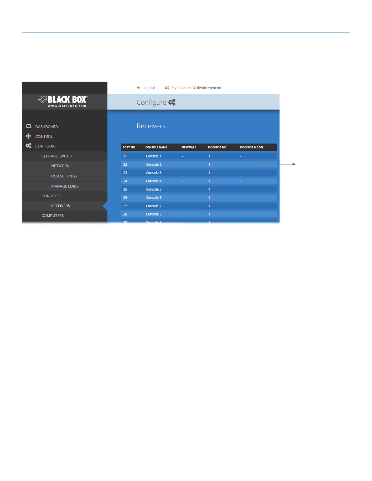
4.7 Configure > Consoles > Receivers
At the heart of each console (the collective term for a set of peripherals connected to the DCX system) is a receiver called a
DCX3000 Remote module.
View details
Click to view
receiver details.
Listed in order of the DCX3000 Switch port to which they are attached, this page shows various details for each DCX3000
Remote module:
• Firmware - the current internal software version for each DCX3000 Remote module.
• Monitor No - an index number for each video display. The first monitor for any console will be indexed as ‘1’. Where a
console has more than one video display associated with it (by using additional DCX3000 Remote modules), this column will
show ‘2’, ‘3’, etc. against the secondary, tertiary, etc. DCX3000 Remote module(s).
• Monitor model - indicates the video display model as reported to the DCX3000 Remote module to which it is connected.
• USB Enabled - indicates the USB status of the DCX3000 Remote module. Where modules are employed to provide
additional video monitor outputs, the USB connections are usually disabled.
• Unique ID - (shown only when the Maintenance > Settings > Web UI Mode is set to Advanced) this column displays the
unique identifier hardwired into every DCX3000 Remote module.
Page 28
724-746-5500 | blackbox.com
Page 29

Chapter 4: Configuration
4.7.1 View receiver details
Click a receiver entry to view the configuration details of the
DCX3000 Switch port to which it is connected.
Within this page it is possible to reboot and/or recover a
re cei ver.
4.7.1.1 Recovering a receiver
This option (shown only when the Maintenance > Settings >
Web UI Mode is set to Advanced) is used to reprogram a
receiver that has failed during a firmware upgrade. Once the
Recover Receiver button is clicked, you will be asked to power
cycle the respective receiver, whereupon it will boot up into
recovery mode. Then you will asked to click a Reprogram button to commence the operation.
724-746-5500 | blackbox.com
Page 29
Page 30

DCX3000 Switch
4.8 Configure > Computers
This page lists the computer systems that are connected to the DCX3000 Switch unit via individual DCX3000 SAM modules:
Add new
Click to add a
new computer. See opposite.
In addition to the Name and Description, the columns also provide the following useful details for
each computer entry:
• Ports - each DCX3000 SAM module connects to a single port on the DCX3000 Switch. This
column lists the port(s) used by the DCX3000 SAM module(s) associated with each computer.
Two or more DCX3000 SAM modules can be combined to support extra displays (multihead), each connecting to a separate port. It may be necessary to delete existing (but unused)
computer/port associations in order to free up ports for the additional module(s). Additionally,
three of the user console ports (21 to 23) can be changed into computer ports, if there are
fewer user consoles within your installation. See Reallocating ports
• Thumbnail - indicates whether a thumbnail image of the computer’s video output will be
shown on the OSD screen for each user. If set to False, a black image will be shown in the OSD
screen.
• Primary Console - indicates the console that currently has control of the computer.
• Connected Consoles - lists all consoles to which each computer is attached.
• Current Access Mode - indicates how the console is permitted to access computers, e.g. View
only, Shared, Exclusive, or Private.
Click an entry to view/edit its details and options.
See opposite.
Edit
Page 30
724-746-5500 | blackbox.com
Page 31

4.8.1 Add new
Click the [+] icon to begin adding a new computer, either before or after connecting the DCX3000 SAM module(s):
• Name - the main identifier for the new computer.
• Description - a further opportunity to add more information about the
computer.
• Ports - Add one or more port numbers used by the DCX3000 SAM module(s)
associated with this computer.
4.8.2 Configure > Computers > Edit an entry
This page allows you to edit the configuration details for a chosen computer.
Chapter 4: Configuration
• Name - the main identifier for the computer.
• Description - a further opportunity to add more information
about the computer.
• Ports - shows the one or more port numbers used by the
DCX3000 SAM module(s) associated with this computer.
For multi-head computers, ensure that the port used by
the primary DCX3000 SAM module (the one linked to the
primary video output) is the first one in the list. It may be
necessary to delete existing (but unused) computer/port
associations in order to free up ports for the additional
module(s). Additionally, three of the user console ports
(21 to 23) can be changed into computer ports, if there
are fewer user consoles within your installation. See
Reallocating ports
• Primary Console - indicates the primary console that is
connected to this computer.
• Connected Consoles - indicates other consoles that are also
connected to this computer.
• Current Access Mode - indicates the access mode (e.g. View
Only, Shared, Exclusive, etc.) that is currently being used for
this computer.
• Transmitters - lists the transmitters (DCX3000 SAM
modules) that are serving this computer.
When you have made your changes, click the Update button.
724-746-5500 | blackbox.com
Page 31
Page 32

DCX3000 Switch
4.9 Configure > Computers > Transmitters
Each computer connects to a DCX3000 SAM transmitter module. This page lists each DCX3000 SAM module and their key
details:
View details
See opposite.
Listed in order of the DCX3000 Switch port to which they are attached, this page shows various
details for each DCX3000 SAM module:
• Computer Name - the given name for each connected computer.
• Firmware - the current internal software version for each DCX3000 SAM module.
• Monitor No - an index number for each video display port. The first port for any computer will
be indexed as ‘1’. Where a computer has more than one video display connected it (by using
additional DCX3000 SAM modules), this column will show ‘2’, ‘3’, etc. against the secondary,
tertiary, etc. DCX3000 SAM module(s).
• Unique ID - (shown only when the Maintenance > Settings > Web UI Mode is set to Advanced)
this column displays the unique identifier hardwired into every DCX3000 SAM module.
Page 32
724-746-5500 | blackbox.com
Page 33
Chapter 4: Configuration
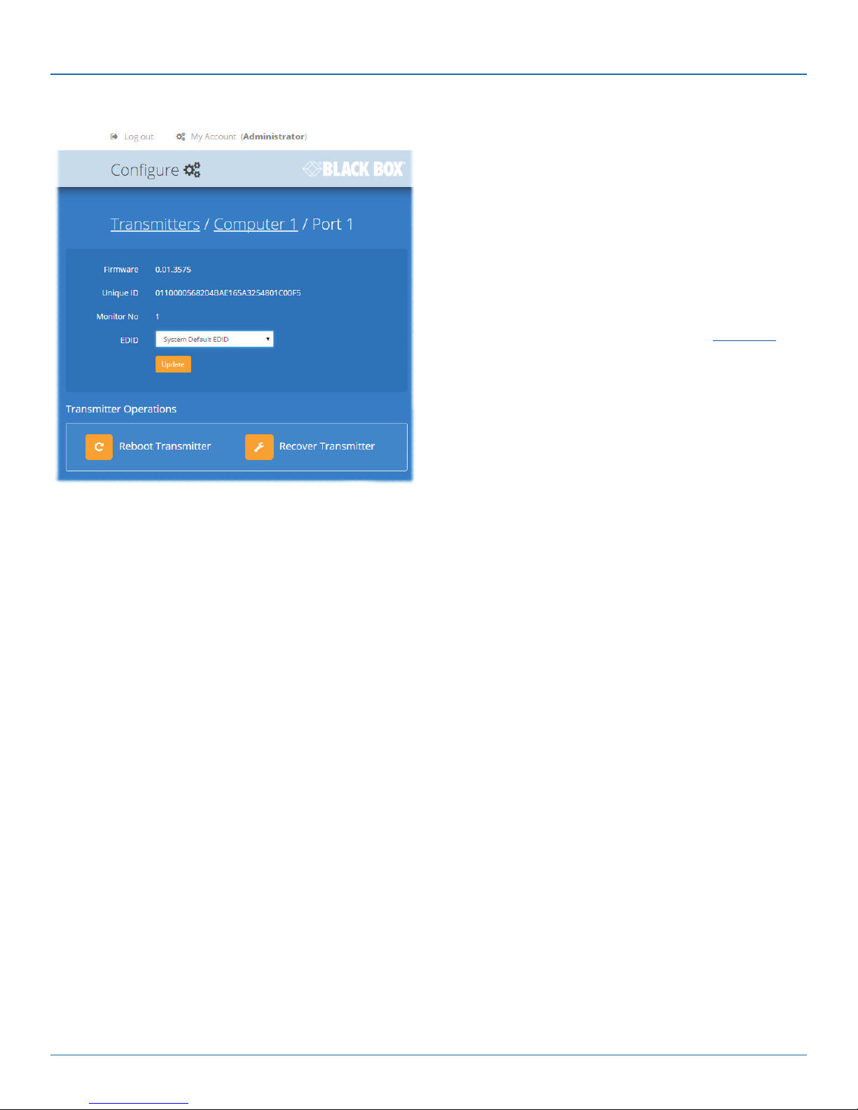
4.9.1 View transmitter details
Click a transmitter entry to view the configuration details of
the DCX3000 Switch port to which it is connected.
Within this page it is possible to reboot and/or recover a
transmitter.
4.9.1.1 Applying a different EDID
If a computer needs to use an EDID profile that differs from
the one being used as the default System EDID, use these
steps:
1 If necessary, clone the required EDID - see Add EDID.
2 View the Configure > Computers > Transmitters page
and click on the required computer entry (to show the
page above).
3 Change the Use System EDID option to Off.
4 Select your cloned EDID using the EDID drop down list.
5 Click the Update button.
4.9.1.2 Recovering a transmitter
This option (shown only when the Maintenance > Settings >
Web UI Mode is set to Advanced) is used to reprogram a
transmitter that has failed during a firmware upgrade. Once
the Recover Transmitter button is clicked, you will be asked to
power cycle the respective transmitter, whereupon it will boot
up into recovery mode. Then you will asked to click a
Reprogram button to commence the operation.
724-746-5500 | blackbox.com
Page 33
Page 34

DCX3000 Switch
4.10 Reallocating ports
By default the DCX3000 Switch provides 20 computer ports along its rear panel and 10 user console ports along its front panel. If
your installation has a greater number of computers or a need for more user consoles, you can alter the allocation of these standard ports:
• Any of the 20 rear panel computer ports can be reallocated as user console ports, or
• Three of the front panel ports (labeled 21 to 23) can be used as computer ports.
When reallocating a port, it is usually necessary to delete it from its default role before using it in its new mode, as follows:
4.10.1 To reallocate a computer port as a user console port
1 Access the Configure > Computers page.
2 Click the entry for the computer port you wish to change.
3 Click the Delete button and then confirm your action in the resulting popup.
4 Access the Configure > Consoles page.
5 Either:
• Click the [+] button to create a new console entry, or
• Click an existing console entry to add the new port to it.
6 Click the Ports down arrow to view the available ports and choose the number of the port that you previously made
available.
7 Add/edit any other details for the console entry and click either the Add Console button or Update button, as appropriate.
4.10.2 To reallocate a user console port as a computer port
1 Access the Configure > Consoles page.
2 Click the entry for the user console port you wish to change.
3 Click the Delete button and then confirm your action in the resulting popup.
4 Access the Configure > Computers page.
5 Either:
• Click the [+] button to create a new computer entry, or
• Click an existing computer entry to add the new port to it.
6 Click the Ports down arrow to view the available ports and choose the number of the port that you previously made
available.
7 Add/edit any other details for the computer entry and click either the Add button or Update button, as appropriate.
Page 34
724-746-5500 | blackbox.com
Page 35

Chapter 4: Configuration
4.11 The Users page
This page lists all registered users and allows the admin user to add, edit and delete entries, as required.
Note: When changes are made to user details, you are recommended to make a backup file.
Change password
Click to change the password for the
user/admin currently logged into DCX
Matrix.
Edit
Click a user entry
to edit its details.
724-746-5500 | blackbox.com
Add new
Click the [+] icon to begin adding a
new us er.
Page 35
Page 36

DCX3000 Switch
4.12 The Maintenance pages
The Maintenance section contains three pages: Diagnostics, System Operations and Settings.
4.12.1 Maintenance > Diagnostics
This page provides important feedback on power inputs (and switch Temperatures). The temperature
information is displayed only when the Maintenance > Settings > Web UI Mode is set to Advanced.
This section indicates the
status of the mains power
input(s).
These items are only shown when
Settings > Advanced Mode On is
chosen.
This section indicates the current
temperature readings within
the DCX3000 Switch for the
following:
• The processor core,
• The internal case area,
• The main circuit board,
• The red, green and blue video
switches.
Page 36
724-746-5500 | blackbox.com
Page 37
Chapter 4: Configuration
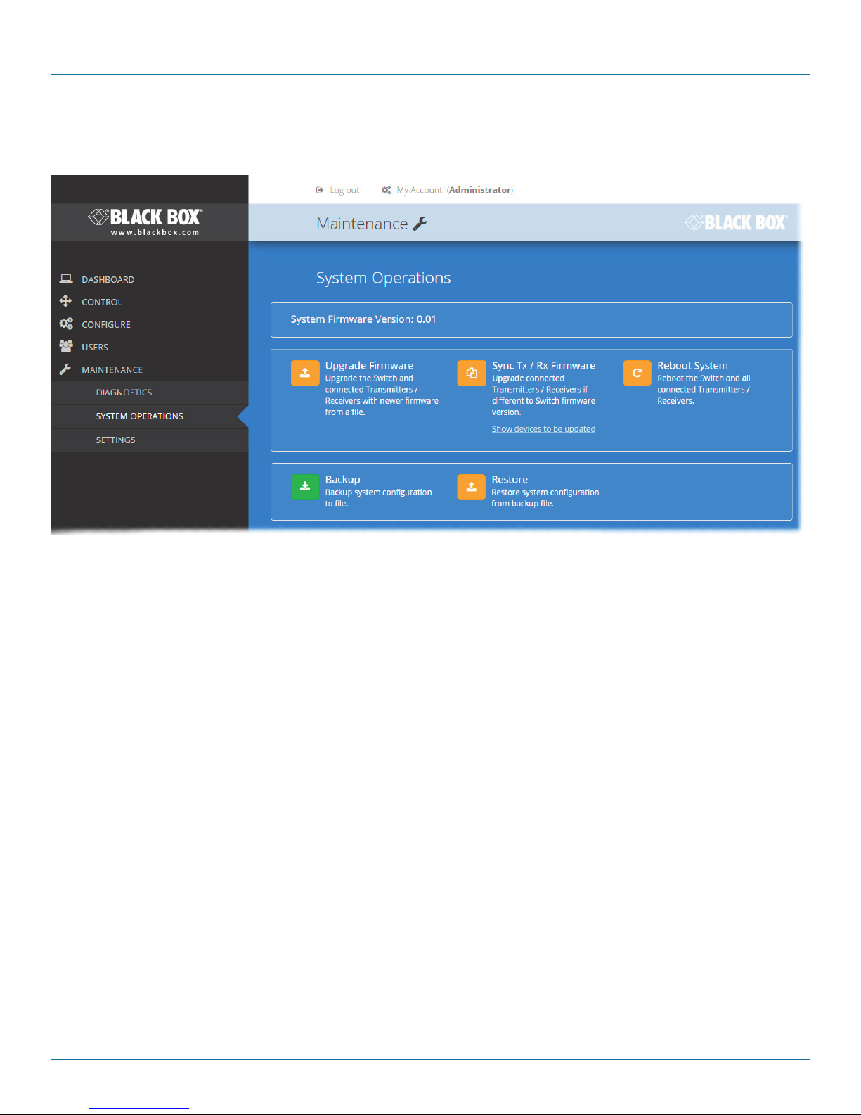
4.12.2 Maintenance > System Operations
This page provides a selection of important system operations that may be required at various times.
Upgrade Firmware
Upgrades the firmwares of all of the
DCX3000 Switch and all connected
modules to the latest version.
Confirmation is required once this
button is clicked.
Backup
Saves a copy of the DCX Matrix
system configuration to a file.
Backup files are stored on the
computer viewing DCX Matrix.
Sync Tx/Rx Firmware
Upgrades the firmwares of all connected
modules to match that of the main switch.
Confirmation is required once this button is
clicked.
Note: Be sure that the DCX3000 Switch has
the latest firmware installed before using
this option.
Restore
Restores the DCX Matrix system
configuration from a backup file. A file
dialog will be displayed to allow you to
choose the filename and location.
Reboot System
Performs a complete reboot
of the entire DCX system,
including the switch and all
modules. Confirmation is
required once this button is
clicked.
724-746-5500 | blackbox.com
Page 37
Page 38

DCX3000 Switch
4.12.3 Maintenance > Settings
This page provides options related to the user interface. When you make a change, you need to click the Update button to save it.
Web UI Mode
When this option is set to Advanced, extra
details are shown on certain pages, such as:
• Configure > Central Switch > General
• Configure > Consoles > Receivers
• Configure > Computers > Transmitters
• Maintenance > Diagnostics
Auto Refresh
When this option is set to On, the Dashboard,
Control and Diagnostic pages will automatically
update their contents every few seconds.
Update
Click this button to save and enact any changes
made to options.
Page 38
724-746-5500 | blackbox.com
Page 39

Chapter 4: Configuration
4.13 Resetting and recovering
There may be rare occasions when the main switch or a module needs to be given a hard reset. The DCX3000 Switch and
DCX3000 Remote module both have concealed reset buttons for this purpose. You need to use a narrow implement (e.g. a
straightened-out paper clip) to press-and-hold the recessed reset button on the front panel:
4.13.1 DCX3000 Switch
4.13.1.1 DCX3000 Switch > Boot into recovery image
This procedure may be necessary if an attempted firmware upgrade has failed. For such a situation the DCX3000 Switch always
retains a recovery image that will return the unit to a working condition, prior to reattempting a firmware upgrade. Note: All configuration data (e.g. users, consoles, computers, networking, etc.) will be retained.
1 Press-and-hold the recessed reset button for ten seconds until the STS (Status) indicator begins to flash slowly.
2 Release the reset button. The STS indicator will go out and the switch will boot itself using the recovery image. The STS
indicator will now begin to flash again to indicate that it is running from the recovery image (a red banner will also be
shown at the top of the DCX Matrix screen).
3 When you are sure of operating conditions, such as having good power stability, proceed once again with the firmware
upgrade.
4.13.1.2 DCX3000 Switch > Full factory reset
This procedure can be used when you wish to clear all data, restore the primary firmware image and return the DCX3000 Switch
to a known state. Note: All configuration data (e.g. users, consoles, computers, networking, etc.) will be deleted.
1 Press-and-hold the recessed reset button for twenty seconds (after ten seconds, the STS indicator will flash as described
above) and then after twenty seconds it will begin to flash at a quicker rate.
2 Release the reset button. The STS indicator will go out while the switch performs the reset and will then illuminate again to
indicate that the factory reset is complete.
724-746-5500 | blackbox.com
Page 39
Page 40

DCX3000 Switch
4.13.2 DCX3000 Remote module
4.13.2.1 DCX3000 Remote module > Boot into recovery mode
This procedure may be necessary if an attempted firmware upgrade has failed. For such a situation the DCX3000 Remote module
always retains a recovery image that will return the unit to a working condition, prior to reattempting a firmware upgrade.
1 Press-and-hold the recessed reset button for ten seconds until the PWR indicator begins to flash quickly.
2 Release the reset button.
3 When you are sure of operating conditions, such as having good power stability, proceed once again with the firmware
upgrade.
4.13.2.2 DCX3000 Remote module > Reset
This procedure may be necessary if a DCX3000 Remote has become unresponsive.
1 Press-and-release the recessed reset button. The DCX3000 Remote module will reboot.
Page 40
724-746-5500 | blackbox.com
Page 41

Chapter 5: Operation
5. Operation
The DCX system is designed to be transparent in operation. A simple OSD (On Screen Display) interface allows each user to view
and select from the available host computers.
5.1 Viewing the OSD
5.1.1 To view the matrix
1 From a console keyboard, press CTRL + ALT + M to display the matrix:
The outputs of the available host computers will be displayed within live thumbnail images.
Note: If video is not available for a computer, or the thumbnail feature has been disabled by the admin user, a black image will be
shown.
5.2 Choosing a computer
5.2.1 To choose a computer using the mouse
1 Hover the mouse pointer over the required screen image. A set of popup connection icons will be displayed:
•
•
•
or
•
For more details, see Access permissions.
Note: If an icon is grayed out, that access method is not available.
2 Click the required connection method. The video output from the chosen computer will be displayed full screen and you
can use it as normal.
View only - you can view a computer’s output but not alter it,
Shared access - you can view and control a computer along with other consoles,
Exclusive - multiple users can view a computer but only one (the first to make connection) can control it,
Private - you can view and control the computer privately while other users are locked out.
5.2.2 To choose a computer using hotkeys
• Press and hold Ctrl + Alt and type the number of the required computer. The video output from the chosen computer will
be displayed full screen and you can use it as normal.
Note: Shared mode is always used when access is made via hotkeys.
724-746-5500 | blackbox.com
Page 41
Page 42

DCX3000 Switch
5.3 Indicators
The DCX3000 Switches, the DCX3000 SAM and DCX3000 Remote modules contain various indicators to provide you with status
information.
5.3.1 DCX3000 Switch - Red front panel status indicators
The red status indicators on DCX3000 Switch front panels provide various key power and operation feedback:
Power input A
This indicator will be
on when power is
supplied to power
socket A
Power input B
This indicator will be
on when power is
supplied to power
socket B
STS (Status)
On: Running primary
firmware image
1Hz flash: Running
backup firmware
image
2Hz flash: Upgrade
mode engaged
ERR
Flashing: Either,
Power input failed or internal error - refer
to the Maintenance > Diagnostics page for
details
or
A firmware mismatch has been detected
with one or more connected devices - refer
to the Dashboard page for details
5.3.2 DCX3000 Switch - Green and amber network status indicators
The green and amber status indicators on the network link port provide further status information:
Amber
Off: 10 or 100Mbps
On: 1000Mbps
Page 42
Green
Off: No link
Flashing: Network activity
On: Quiescent link
724-746-5500 | blackbox.com
Page 43

Chapter 5: Operation
5.3.3 DCX3000 Remote module - Green and amber status indicators
The green and amber indicators on the link port of each DCX3000 Remote module provide the following status information:
Amber
Off: No power
Flashing: Power present but
either no video or
video not locked
On: Power present and
video locked
Green
Off: No power
Flashing: Power present but no data link
On: Power present and link established
5.3.4 DCX3000 Remote module - Red front panel status indicators
The red indicators on the front panel of each DCX3000 Remote module provide the following status information:
Special condition
PWR on, Amber flashing and Green off: Software fault
requiring the DCX3000 Remote module to be recovered.
See Configure > Consoles > Receivers.
LNK
Off: No power or no link
Flashing: Switch refused
link connection due to
incompatible firmware
versions
On: Link established
USB
Off: No power or no active USB
connection
Flashing: USB connection is contended in
shared mode (keyboard LEDs also flash)
On: USB is routed to a DCX3000
SAM module, either via the DCX3000
Switch or directly, in a simple extender
installation
VID
Off: No power
present or the
video is not locked
On: Power present
and video locked
PWR
Off: No power present
Slow flashing: A firmware upgrade is
being forced by the DCX3000 Switch
Fast flashing: Receiver in USB recovery
mode
On: Power present
5.3.5 DCX3000 SAM module - Green and amber status indicators
The green and amber indicators on the link port of each DCX3000 SAM (computer) module provide the following status information:
Amber
Off: No power
Flashing: Power present but
no video
On: Power present and
video locked
Green
Off: No power
Slow flashing: Power present but no data link
Fast flashing: A firmware upgrade is being forced by either the DCX3000 Switch or a DCX3000 Remote
On: Power present and link established
Special condition
Amber flashing and Green off: Software fault requiring the DCX3000
SAM module to be recovered. See Configure > Computers >
Transmitters.
724-746-5500 | blackbox.com
Page 43
Page 44

DCX3000 Switch
Appendix A. Safety Information
• For use in dry, oil free indoor environments only.
• Do not use to link between buildings.
• Ensure that the twisted pair interconnect cable is installed in compliance with all applicable wiring regulations.
• Do not connect the CATx link interface (RJ45 style connector) to any other equipment, particularly network or telecommunica-
tions equipment.
• Warning – the power adapter contains live parts.
• No user serviceable parts are contained within the power adapter - do not dismantle.
• Plug the power adapter into a grounded socket outlet close to the unit that it is powering.
• Replace the power adapter with a manufacturer approved type only.
• Do not use the power adapter if the power adapter case becomes damaged, cracked or broken or if you suspect that it is not
operating properly.
• If you use a power extension cord with the units, make sure the total ampere rating of the devices plugged into the extension
cord do not exceed the cord’s ampere rating. Also, make sure that the total ampere rating of all the devices plugged into the
wall outlet does not exceed the wall outlet’s ampere rating.
• Do not attempt to service the units yourself.
• The units and power supplies can get warm in operation – do not situate them in an enclosed space without any ventilation.
• The units do not provide ground isolation and should not be used for any applications that require ground isolation or galvanic
isolation.
Page 44
724-746-5500 | blackbox.com
Page 45

Black Box Tech Support: FREE! Live. 24/7.
Tech support the
way it should be.
Great tech support is just 60 seconds away at 724-746-5500 or blackbox.com.
About Black Box
Black Box Network Services is your source for an extensive range of networking and infrastructure products. You’ll find everything
from cabinets and racks and power and surge protection products to media converters and Ethernet switches all supported by
free, live 24/7 Tech support available in 60 seconds or less.
© Copyright 2015. Black Box Corporation. All rights reserved.
DCX3000, rev. 1.0a
724-746-5500 | blackbox.com
 Loading...