

Page 1
Cold Row™ Chilled Water (CW) Engineering Manual
This precision data center air-conditioning system
uses the latest, state-of-the-art control technology.
CRCW-12
CRCW-24
Customer
Support
Information
Order toll-free in the U.S.: Call 877-877-BBOX (outside U.S. call 724-746-5500)
FREE technical support 24 hours a day, 7 days a week: Call 724-746-5500 or fax 724-746-0746
Mailing address: Black Box Corporation, 1000 Park Drive, Lawrence, PA 15055-1018
Web site: w ww.blackbox.com • E-mail: info @blackbox.com
Page 2

724-746-5500 | blackbox.com
Trademarks Used in this Manual
Trademarks Used in this Manual
Black Box and the Double Diamond logo are registered trademarks, and Cold Row is a trademark, of BB Technologies, Inc.
Armaflex is a registered trademark of Armacell Enterprise GmBH.
UL is a registered trademark of Underwriters Laboratories.
Any other trademarks mentioned in this manual are acknowledged to be the property of the trademark owners.
Page 2
724-746-5500 | blackbox.com
Page 3

Table of Contents
Table of Contents
1. About the Cold Row CW ......................................................................................................................................................4
2. Features ...............................................................................................................................................................................5
3. Configurations ....................................................................................................................................................................... 7
4. Technical Data ....................................................................................................................................................................... 8
5. Performance, Electrical, and Sound Data ...............................................................................................................................9
6. Dimensional Data ................................................................................................................................................................13
7. Product Features .................................................................................................................................................................. 15
8. Product Guide Specifications ...............................................................................................................................................16
724-746-5500 | blackbox.com
Page 3
Page 4

724-746-5500 | blackbox.com
Chapter 1: About the Cold Row CW
1. About the Cold Row CW
Designed for scalability, reliability, and seamless integration into new or existing data centers; the rack cooling systems are suitable
for use in open and contained hot-aisle and cold-aisle configurations. The models covered in this manual are ideal for hot-spot
cooling in small- to enterprise-size data centers.
Typical applications include:
• Internet/Web hosting
• Telecommunications
• Financial/banking
• Insurance
• Airlines/mass transit
• Legal services
• Entertainment
• Government
• Colleges/universities
• Data centers
• Computer/LAN rooms
• Telecommunications rooms
• Co-location centers
• Internet service providers (ISPs)
• Applications service providers (ASPs)
• Hospital operating and isolation rooms
Page 4
724-746-5500 | blackbox.com
Page 5

Chapter 2: Features
2. Features
Chilled water (CW) is supplied to the Cold Row CW unit via a building chiller or other chilled water plant. Chilled water has high
affinity for heat, making it a very efficient cooling method. The E² controller enables independent valve and fan control so the unit
can adjust immediately, and precisely, to varying heat loads and optimize energy efficiency.
Two models are available:
Table 2-1. Available models.
Produc t Code Produc t Name
CRCW-12 Cold Row CW, 12"
CRCW-24 Cold Row CW, 24"
The Cold Row CW offers the following features:
• Highest cooling capacities in the industry.
• 12" and 24" cabinet width.
• 3 EC fans: Independently and infinitely adjustable EC fans ensure maximum efficiency.
• Used in containment, open architecture, and hot spot reduction applications.
• Adapts to both high- and low-density IT environments.
• Wide range of cooling capacities available.
• 100% front and rear service access.
• Adapts to all major manufacturers' racks and rack containment systems.
• Integrates seamlessly with all Building Management Systems (BMS) platforms.
• Private VLAN (pLAN) link to 8 units without a BMS.
• High airflow with low noise.
• Built-in redundancy and capacity assist functions.
• Top and bottom piping options.
• Casters and leveling feet included.
• Indoor use only.
• Installation on raised and non-raised floors.
724-746-5500 | blackbox.com
Page 5
Page 6
724-746-5500 | blackbox.com
Chapter 2: Features
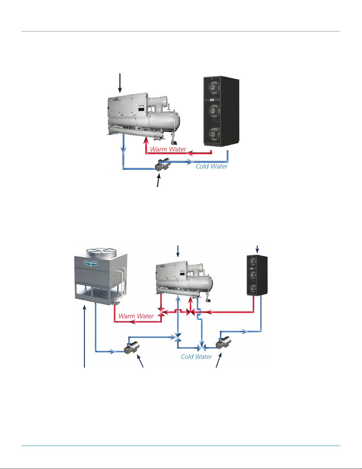
Chiller
(Full Capacity
or Tr im )
Cold Row CW
Chilled Water
Pump
Closed Loop
Cooling Tower
Figure 2-1. Traditional cooling example.
Chiller
Cooling Tower Pump
Chilled Water Pump
Cold Row CW
Page 6
Figure 2-2. Hybrid-free cooling diagram.
724-746-5500 | blackbox.com
Page 7
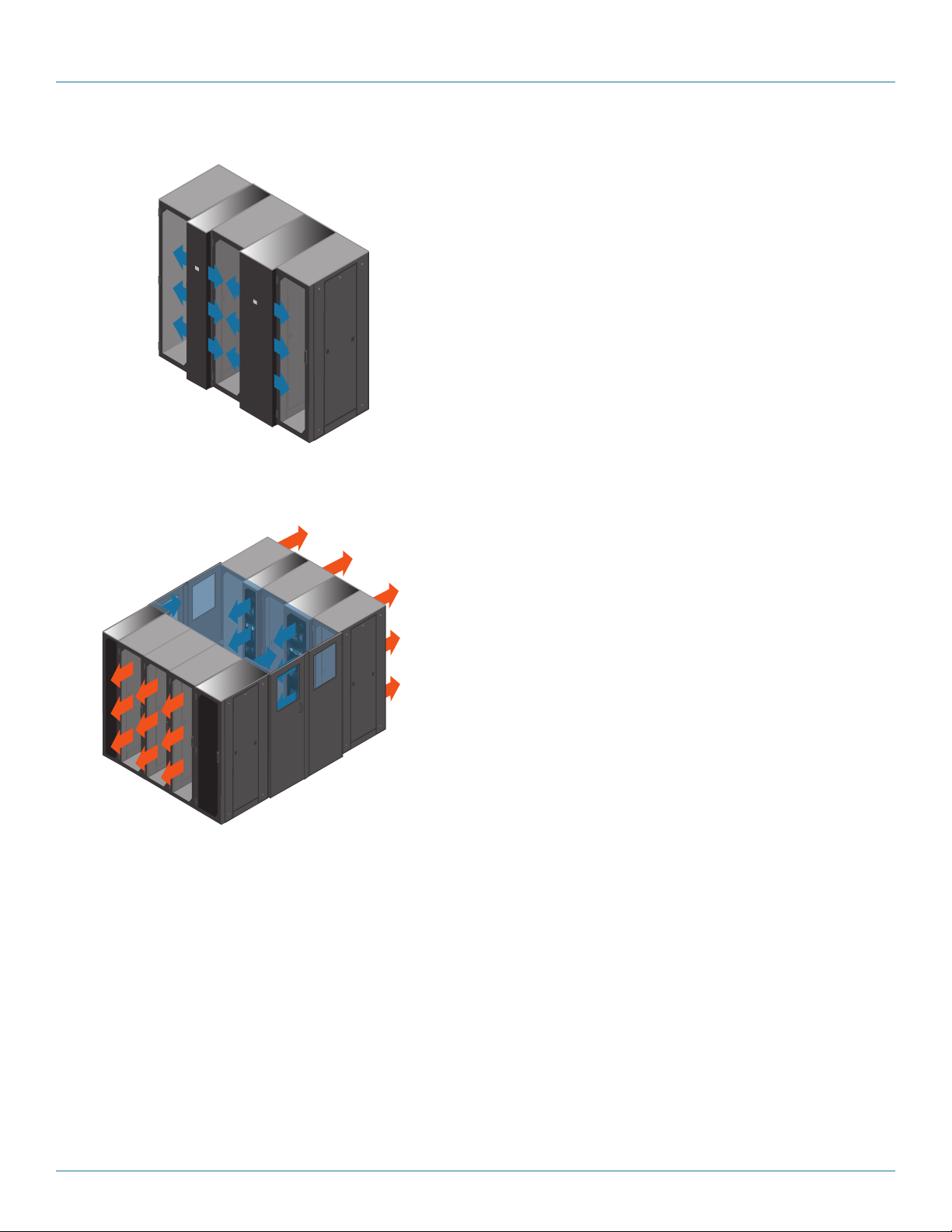
Open Aisle
Containment with
Side Discharge
Chapter 3: Configurations
3. Configurations
Open Aisle Configuration
Open aisle configuration organizes racks in a single row or in hot
and cold aisle rows, but without containment. The Cold Row
CW draws hot air from the external environment or hot aisle,
removes the heat, and supplies cooled air to the front of IT
equipment in the cold aisle.
Cold Aisle
Containment with
Front Discharge
Cold Aisle Containment
Cold aisle containment captures cooled air from the Cold Row
CW and prevents it from mixing with hot air. The front of IT
equipment is accessed in the contained cold aisle. The Cold Row
CW draws hot air from the external environment, removes the
heat, and supplies cooled air back into the contained cold aisle.
724-746-5500 | blackbox.com
Page 7
Page 8

724-746-5500 | blackbox.com
Chapter 4: Technical Data
4. Technical Data
Table 4-1. CW System Technical Data.
Model 12" Chilled Water, CRCW-12 24" Chilled Water, CRCW-24
Chilled Water Control Valve
2-Way (Standard) — Modulating
Valve Pressure Rating — psi 400 400
Close-off Pressure Rating — psi 200 200
3-Way (optional) — Modulating
Valve Pressure Rating — psi 400 400
Close-off Pressure Rating — psi 200 200
Chilled Water Coil — Aluminum Fin, Copper Tube
2
Rows/ Face Area (ft.
) 4/5.8 4 /11 .6
Face Velocity, fpm 500 500
Blower/Motor — Backward Curved Direction Driven EC
Horsepower (Each) 1 /4 H . P. 1- 1/ 4 H .P.
CFM 2,900* 5,800
Quantity of Blowers 3 3
Drive Method Direct Direct
Humidification: Electrode Steam Canister Humidifier with Adjustable Output (Optional)
lb./ hr. (KW input) N/A 5 (1.7)
Std Control N/A Proportional
Washable Filters
Nom. Size (in.) (Qty,) 10.5 x 37.38 x 0.43 (2) 22.0 x 37.37 x 0.43 (2)
Connection Sizes (Copper)
Condensate Drain (w/pump) 1/2" FP T 1/2" FPT
Humidifier Inlet N/A 1/4" OD
Water In/ Out 1-1/4" NP T 1-1/ 2" N PT
Physical Data
Approx. Weight (lb.) 384 550
Dimensions: (H" x W" x D") 78.5" x 11.6" x 42.1" 78.5" x 23.4" x 42.1"
Approx. Shipping Weight 570 7 11
Approx. Shipping Dimensions:
(H" x W" x D")
84" x 22" x 4 8" 84" x 32" x 48"
*NOTE: When 110v/Ph/60 Hz power input is selected, unit airflow is reduced by 200 CFM, which will result in capacity reduction
of 3.5% or less.
724-746-5500 | blackbox.com
Page 8
Page 9

Chapter 5: Performance, Electrical, and Sound Data
5. Performance, Electrical, and Sound Data
Table 5-1. Performance Data.
12" Chilled Water
(C RCW -12)
100° F DB/ 69.2° F WB Entering AIr Temperature
40° F EWT
45° F EW T
50° F EWT
95 FDB/67.7° F WB Entering AIr Temperature
40° F EWT
45° F EW T
50° F EWT
Temperature
Change
10° F Temperature
change
12° F Temperature
change
10° F Temperature
change
12° F Temperature
change
10° F Temperature
change
12° F Temperature
change
10° F Temperature
change
12° F Temperature
change
10° F Temperature
change
12° F Temperature
change
10° F Temperature
change
12° F Temperature
change
Total Capacity Sensible Capacity Flow Rate
BTU/H kW BTU/H kW GPM (ft. H
12 7,0 08 37. 2 125, 200 36.7 25.7 18.0
119 ,4 61 35.0 119 ,4 61 35.0 20.2 12.2
107,333 31.4 107,333 31.4 21.8 13.7
102,8 55 3 0.1 102, 855 30 .1 17. 4 9.6
95 ,717 28.0 95 ,717 28.0 19.5 11. 4
91,5 61 26.8 91,561 26.8 15 .5 8.0
116 ,10 7 34.0 113, 55 4 33.2 23.5 15.5
108,271 31.7 108 ,271 31.7 18.3 10.5
96,465 28.2 96,465 28.2 19.6 11. 6
91,8 34 26.9 91, 834 26.9 15.6 8.2
84,669 24.8 84,669 24.8 17. 3 9.5
80 ,417 23.5 80 ,417 23.5 13.7 6.8
Total System
Pressure Drop
O)
2
90° F DB/ 66.1° F WB Entering AIr Temperature
40° F EWT
45° F EW T
50° F EWT
10° F Temperature
change
12° F Temperature
change
10° F Temperature
change
12° F Temperature
change
10° F Temperature
change
12° F Temperature
change
108,988 31.9 10 8,988 31.9 2 2.1 14.0
103,324 30.3 103, 324 30.3 17. 5 9.7
96 ,139 28.2 9 6,13 9 28.2 19.5 11 .5
91,959 26.9 91,9 59 26.9 15.6 8.2
84,788 24 .8 84,788 24.8 17. 3 9.5
80,524 23.6 80,524 23.6 13.7 6.8
724-746-5500 | blackbox.com
Page 9
Page 10

724-746-5500 | blackbox.com
Chapter 5: Performance, Electrical, and Sound Data
Table 5-1 (continued). Performance Data.
12" Chilled Water
(C RCW -12)
80° F DB/ 64.5° F WB Entering AIr Temperature
40° F EWT
45° F EW T
50° F EWT
24" Chilled Water
(CRCW-24)
100° F DB/ 69.2° F WB Entering AIr Temperature
Temperature
Change
10° F Temperature
change
12° F Temperature
change
10° F Temperature
change
12° F Temperature
change
10° F Temperature
change
12° F Temperature
change
Temperature
Change
Total Capacity Sensible Capacity Flow Rate
BTU/H kW BTU/ H kW GPM (ft. H
81,15 5 23.8 77,1 51 22.6 16.6 9.0
72,250 21. 2 72,250 21.2 12. 3 6.0
61,703 18 .1 61,703 18 .1 12 .6 6.2
56,587 16.6 56,587 16.6 9.7 4.5
49,48 8 14 .5 49,488 14.5 10.2 4.8
44,393 13.0 33,393 13. 0 7. 7 3.7
Total Capacity Sensible Capacity Flow Rate
BTU/H kW BTU/ H kW GPM (ft. H
Total System
Pressure Drop
O)
2
Total System
Pressure Drop
O)
2
10° F Temperature
40° F EWT
45° F EW T
50° F EWT
95° F DB/67.7° F WB Entering AIr Temperature
40° F EWT
45° F EW T
50° F EWT
change
12° F Temperature
change
10° F Temperature
change
12° F Temperature
change
10° F Temperature
change
12° F Temperature
change
10° F Temperature
change
12° F Temperature
change
10° F Temperature
change
12° F Temperature
change
10° F Temperature
change
12° F Temperature
change
26 3,192 7 7.1 250,429 73.3 54.5 39.4
251, 539 73.7 245,539 71.9 43.5 26.8
219,8 54 64.4 219, 854 64.4 45.9 29.2
211, 92 7 6 2.1 211, 92 7 6 2.1 3 7.0 20.2
192,259 56.3 192,259 56.3 40.5 23.4
186,556 54.6 186, 556 54.6 32.8 16.5
242,729 7 1.1 2 27,7 17 66.7 50.5 34.8
230,726 6 7.6 222,663 65.2 4 0.1 23.3
199, 089 58.3 19 9,0 89 58.3 41. 8 24.9
190,287 55.7 190,287 55.7 33.4 17. 0
170,77 2 50.0 17 0,77 2 50.0 36.2 19.4
164,228 4 8.1 16 4,228 4 8.1 29.0 13.4
Page 10
724-746-5500 | blackbox.com
Page 11

Chapter 5: Performance, Electrical, and Sound Data
Table 5-1 (continued). Performance Data.
24" Chilled Water
(CRCW-24)
90° F DB/ 66.1° F WB Entering AIr Temperature
40° F EWT
45° F EW T
50° F EWT
85° F DB/64.5° F WB Entering AIr Temperature
40° F EWT
45° F EW T
50° F EWT
80° F DB/ 62.8° F WB Entering AIr Temperature
40° F EWT
45° F EW T
50° F EWT
Temperature
Change
10° F Temperature
change
12° F Temperature
change
10° F Temperature
change
12° F Temperature
change
10° F Temperature
change
12° F Temperature
change
10° F Temperature
change
12° F Temperature
change
10° F Temperature
change
12° F Temperature
change
10° F Temperature
change
12° F Temperature
change
10° F Temperature
change
12° F Temperature
change
10° F Temperature
change
12° F Temperature
change
10° F Temperature
change
12° F Temperature
change
Total Capacity Sensible Capacity Flow Rate
BTU/H kW BTU/ H kW GPM (ft. H
221,10 8 6 4.7 204,623 59.9 46.2 29.8
20 7,9 22 60.9 199,053 58.3 36.2 19.6
17 7,3 57 51.9 17 7,3 57 51. 9 37. 4 20.3
16 7,3 55 49.0 16 7,3 55 49.0 29.5 14.0
148 ,407 43.5 148,407 43.5 31.6 15. 4
141,408 41.4 141,408 41. 4 25.2 10.8
199,491 58.4 180,880 53.0 41. 8 25.0
184,737 5 4.1 174, 604 51.1 32.4 16.3
154 ,771 45.3 15 4,771 45.3 32.9 16.7
144 ,039 42.2 144,039 42.2 25.6 11 .1
125, 357 36.7 125 ,357 36.7 27. 0 12 .1
117, 88 2 34.5 117, 88 2 34.5 21.3 8.5
176,4 42 51.7 156,565 45.8 37. 2 20.6
159, 804 46.8 149,444 43.8 28.2 13 .0
130 ,953 38.3 130 ,953 38.3 28.2 12.9
119 ,74 2 3 5.1 119 ,74 2 3 5.1 21.6 8.7
101,6 25 29.8 101, 625 29.5 22.3 9.0
93,093 27. 3 93,093 27.3 17.1 6.3
Total System
Pressure Drop
O)
2
724-746-5500 | blackbox.com
Page 11
Page 12

724-746-5500 | blackbox.com
Chapter 5: Performance, Electrical, and Sound Data
Table 5-2. Electrical Data.
Electrical Data
Cooling Only
120 /1/ 60 9.5 11.9 15 N/A N/A N/A
208/1/60 5.7 7.1 15 N/A N/A N/A
208/3/ 60 5.7 7.1 15 10.0 12.5 15
460/3/60 2.8 3.6 15 4.8 6.0 15
575/3/60 2.3 2.9 15 3.9 4.9 15s
Cooling and Humidifier
120 /1/ 60 N/A N/A N/A N/A N/A N /A
208/1/60 N/A N/A N/A N/A N/A N /A
208/3/ 60 N/A N/A N/A 19.2 24.0 30
460/3/60 N/A N/A N/A 9.0 11 .2 15
575/3/60 N/A N /A N /A 7. 3 9.1 15
CRCW -12 CRCW-24
FLA MCA MFS FLA MCA MFS
NOTE: Standard 1 KAIC rating; optional 65 KAIC rating available.
Table 5-3. Sound Data.
Sound Data for CRCW-12 Sound Pressure — LpA, free field (dBA) in a 121.13 ft.2 (3.43 m3) room at 3.28 (1.0 m) distance
Fan Speed % Airflow ( SCFM) 63 125 250 500 1000 2000 4000 8000 Tot al dBA NR Value
50% 180 0 15.8 19.7 31. 3 35.0 38.8 3 6.1 25.3 10.9 42.0 39
75% 2150 13.1 41.6 42.7 45.2 4 8.1 46.2 38.5 23.4 52.6 48
100% 2900 19.6 4 7.2 49.8 51. 4 53.6 51.7 45.0 30.6 58.4 54
2
Sound Data for CRCW-24 Sound Pressure — LpA, free field (dBA) in a 146.91 ft.
Fan Speed % Airflow ( SCFM) 63 125 250 500 1000 2000 4000 8000 Tot al dBA NR Value
50% 410 0 29.4 42.5 46.6 48.6 52.3 52.5 41.5 2 6.1 5 7.0 54
75% 5000 34.9 49.7 5 7.3 59.7 62.8 60.5 56.0 40.3 6 7.0 63
100% 5800 43.0 52.6 61.5 64.0 6 7.0 64.2 59.6 45.8 7 1.1 67
(4.16 m3) room at 3.28 (1.0 m) distance
NOTE: All sound testing is performed in accordance with ISO 9614-2 Determination of Sound Power Levels. ISO 9614-2 specifies
a method for measuring the component of sound intensity that is normal to a measurement surface. The measurement
surface is chosen to enclose the noise source(s) so that the sound power level can be determined.
Page 12
724-746-5500 | blackbox.com
Page 13

6. Dimensional Data
Chapter 6: Dimensional Data
77. 8"
11. 6"
Air
In
Top Piping Option
Power
Connections
Piping
Connections
Condensate
Connection
Bottom Piping Option
42 .1"
Air
Out
Figure 6-1a. Size and piping options, CRCW-12.
Condensate
Connection
Piping
Connections
Power
Connections
724-746-5500 | blackbox.com
Page 13
Page 14

724-746-5500 | blackbox.com
Chapter 6: Dimensional Data
11.6"
77.8"
48.3"
Side-Diverted Front Panel Piping Option, CRCW-12
Figure 6-1b. Size and piping options, CRCW-12.
Page 14
724-746-5500 | blackbox.com
Page 15

Chapter 6: Dimensional Data
Top Piping Option
23.4"
Air
In
77. 8"
Humidifier
Connections
Power
Connections
Piping
Connections
Condensate
Connection
Bottom Piping Option
Piping
Connections
42 .1"
Air
Out
Power
Connections
Figure 6-2a. Size and piping options, CRCW-24.
Condensate
Connection
Humidifier
Connection
724-746-5500 | blackbox.com
Page 15
Page 16

724-746-5500 | blackbox.com
Chapter 6: Dimensional Data
Side-Diverted Front Panel Piping Option, CRCW-24
Page 16
Figure 6-2b. Size and piping options, CRCW-24.
724-746-5500 | blackbox.com
Page 17

7. Product Features
Features Part Numbers
Cabinet CRCW -12 CRCW-24
Galvanized Steel, Black Power-Coated Finish Standard Standard
Air Pat tern and Filtration
Front Discharge Standard Standard
Front Diverted Plenum Discharge Optional Optional
Permanent Washable Filters Standard Standard
Mechanical Components
Backward Inclined, Plenum-Style Fan, with an EC Motor Standard Standard
Chilled Water Cooling Coil Standard Standard
Piping Configuration (Top or Bottom) Selectable* Selectable*
Condensate Pump Standard Standard
Chapter 7: Product Features
Table 7-1. Product features.
2-Way Modulating Chilled Water Control Valve Standard Standard
3-Way Modulating Chilled Water Control Valve Optional Optional
Electrode Steam Condenser Humidifier N/A Optional
Electrical System
Automatic Dual Power Transfer Switch Optional Optional
Remote Stop /Start Controls Standard Standard
Main Power Switch Standard Standard
2
Microprocessor Controller
E
A/ C Grouping pLAN Interface Optional Optional
BMS Interface Optional Optional
Common Alarm, Dry Contact Standard Standard
Optional Accessories
Mechanical Flow Switch Optional Optional
Differential Temperature Flow Optional Optional
Smoke Detection Optional Optional
Firestat Optional Optional
Remote Water Detec tor Optional Optional
Code Conformance
®
ETL Conformance Compliance to UL
CAN /CSA C22.2 No. 236 Standard Standard
1995 Standard Standard Standard
*NOTE: Piping connection location to be specified at time of order.
724-746-5500 | blackbox.com
Page 17
Page 18

724-746-5500 | blackbox.com
Chapter 8: Product Guide Specifications
8. Product Guide Specifications
SUMMARY
This specification describes requirements for a precision environmental control system. The Cold Row CW is a row-based cooling
system that provides precision temperature control (and humidity control for the 24" models) for computer rooms, or rooms
containing telecommunications or other highly sensitive heat load equipment, where continuous 24 hours a day, 365 days a year
air conditioning is required. Designed with both front and rear access, Cold Row CW systems require minimum floor space. The
supplied system has ETL Certification. The part numbers are CRCW-12 and CRCW-24.
DESIGN REQUIREMENTS
The environmental control system is a Cold Row Chilled Water (CW) factory-assembled unit. The unit is designed for a
row-based installation with removable front and rear access panels. No allowance for side service access is required, however,
removable side access panels are provided for additional access.
Cold Row CW units are especially adapted for both raised and non-raised floors. The air handling system is specifically designed
for high sensible heat ratio. Each system is capable of handling ___CFM. The unit shall have the cooling capacity of ___BTU/H,
and the sensible cooling capacity of ___BTU/H based on entering air condition of ___°F (°C) dry bulb and ___°F (°C) wet bulb.
The main fan motors shall be ___HP. The unit shall have a power supply of ___volts.
QUALITY ASSURANCE
The manufacturer will maintain a set of international standards of quality management to ensure product quality. Each system will
be subjected to a complete operational and functional test procedure at the factory before shipment.
CABINET
Access panels must be fabricated from 18-gauge galvannealed steel and must be securely fastened to the 10-gauge base and
16-gauge top plates, fabricated from galvannealed steel. Both must be painted with a 2-ply epoxy finish to match and to protect
from corrosion. The main unit color shall be satin black. Armaflex® elastomeric thermal insulation must be used to insulate the
cabinet, block noise, and prevent damage from vibration. Casters and leveling feet shall be included to ease the installation and
level the equipment with existing IT solutions.
AIRFLOW PATTERNS
All units must be designed using a front discharge with a rear return airflow pattern. An optional plenum with a front diverted
discharge pattern is available.
AIR FILTRATION
All units must be equipped with permanent washable filters. These filters must consist of an open cell structured polyurethane
foam with a roll-formed 3000 series aluminum frame. Filters shall meet both UL® 900 and UL 94 HF-1 standards.
MECHANICAL COMPONENTS
BACKWARD-INCLINED, PLENUM-STYLE FAN, WITH AN EC MOTOR
The blowers must be backward-inclined, plenum-style fans with an electronically commutated (EC) motor, for maintenance-free
operation. The motor must include: integrated electronic control board and direct microprocessor control signaling for fan speed
control, soft-starting capabilities, and integrated current limitations. Each fan must be low noise, low vibration manufactured with
an anti-corrosive aluminum impeller. Each fan impeller must be dynamically and statically balanced in two planes to minimize
vibration during operation.
Page 18
724-746-5500 | blackbox.com
Page 19

Chapter 8: Product Guide Specifications
CHILLED WATER COOLING COIL
The coil must be constructed of seamless drawn copper tubes, mechanically bonded to tempered aluminum fins with enhanced
fin design for maximum heat transfer, and mounted in a stainless steel condensate drain pan. The coil must be designed for a
maximum of 500 ft./min. face velocity. The water circuit will be designed to distribute water into the entire coil face area.
PIPING CONFIGURATION
Top piping: When top piping is specified, the Cold Row CW units must be provided with connections for both chilled water
piping and condensate discharge on the top of the cabinet.
Bottom piping: When bottom piping is specified (for example, raised floor applications), the Cold Row CW units must be provided
with connections for both chilled water and condensate pump discharge through the bottom of the cabinet.
CONDENSATE PUMP
The Cold Row CW must include a factory-wired and installed, in-pan condensate pump. The condensate pump must have the
capacity of 40 gal/hr. at 6 ft. of lift with a maximum shutoff (head) of 12 ft. The condensate pump must be piped with either top
or bottom discharge connections, to remain consistent with top or bottom chilled water piping connections.
2-WAY (STANDARD)
A 2-way modulating valve rated for a maximum 400 psig w.w.p. must be factory piped and wired. The 2-way chilled water
modulating valve will automatically meter the flow of chilled water to the cooling coil in response to a proportional signal
(0–10 VDC) provided to the valve by the microprocessor controller w.w.p.
3-WAY (OPTIONAL)
The water circuit must include a factory-mounted, 3-way modulating (0–10 VDC) control valve. Design pressure must be
400 psig.
STEAM-GENERATING HUMIDIFIER FOR 24" CABINET DESIGN (CRCW-24)
The humidifier must be a self-contained, steam-generating electrode type, using a plastic disposable cylinder with full probes,
connected to electric power via cylinder plugs that slide onto the electrode pins. The electrode pins must be constructed from
expanded low carbon steel, zinc plated, and dynamically formed for precise current control. The humidifier assembly must include
an integral fill cup, fill and drain valves, and associated piping.
The canister must be designed to collect the mineral deposits in the water and provide clean, particle-free steam to the air stream,
reducing maintenance cost.
The microprocessor control must maintain humidifier operation through fill and drain cycles based on the water conductivity.
Overflow and loss of flow protection shall be provided along with a manual drain switch. A high water alarm with built-in time
delay shall provide an indication to change canister. The humidification system must not require cleaning maintenance during the
cylinder life.
The humidifier must discharge steam at 212 degrees F and atmospheric pressure. It must be capable of operating with water in
the range of 200 to 1500 micromhos. The steam must be introduced into the air stream, after the evaporator, by a calibrated
discharge tube designed to equally distribute the steam to the air stream without condensation. The humidifier must have a
capacity of 5 lb./hr.
A factory-wired and installed humidifier drain pump must be installed. This pump is designed to operate with the higher
condensate temperatures caused by the flush and drain cycle of the electrode canister humidifiers. The humidifier drain line will
be connected to the main condensate line prior to exiting the cabinet.
DEHUMIDIFICATION CYCLE
The Cold Row CW unit must have a dehumidification control mode. During dehumidification demand, the control mode must
permit chilled water valve operation and EC motor speed control to condense moisture on the cooling coil.
724-746-5500 | blackbox.com
Page 19
Page 20

724-746-5500 | blackbox.com
Chapter 8: Product Guide Specifications
ELECTRICAL SYSTEM
The electrical system must conform to National Electrical Code (NEC) requirements. In accordance with NEC Class II requirements,
the control circuit must be 24 volts AC wire, and control circuit wiring must not be smaller than 18 AWG. All wiring must be
neatly wrapped, or run in conduit, or cable trays, and routed in bundles. Each wire must end with a service loop and be securely
fastened by an approved method. Each wire in the unit must be numbered for ease of service tracing.
All electrically actuated components should be easily accessible from the front of the unit without reaching overexposed
high-voltage components or rotating parts. Each high-voltage circuit should be individually protected by circuit breakers, or
manual motor starters, on all three phases. The blower motor must have thermal and short-circuit protection. Line voltage and
24-volt control circuit wiring must be routed in separate bundles. The electric box must include all the contactors, starters, fuses,
circuit breakers, and terminal boards required for operation of the Cold Row unit. It must also allow for full service via front and
rear access panels.
AUTOMATIC DUAL POWER TRANSFER SWITCH (OPTIONAL)
Two individual main power input disconnect switches will be provided, one for each incoming power source. If the primary power
fails or a phase loss/imbalance occurs, the automatic transfer switch transfers power to the secondary power source. Once the
primary power has been restored, the transfer switch automatically shifts the power load back to the primary power. The transfer
time from one source to the other is user adjustable to allow staging or sequence restart of load.
In addition to the automatic transfer switch function, the local controller display will indicate which power source has failed. This
indication is a visual depiction that allows the user to determine the status of the input source. This status can also be conveyed
thru the BMS serial communication link.
REMOTE STOP/START CONTACTS
Included in the system’s electrical control circuit must be a 2-pin terminal connection for remote stop/start of the Cold Row CW
air conditioner by remote source.
MAIN POWER SERVICE SWITCH
The Cold Row CW must have a unit-mounted main power service switch.
E2 Series Controller Description
GENERAL
The advanced microprocessor based E² Series controller must be equipped with flexible software that meets the specific needs
of the application. The setpoints must be default and their ranges must be easily viewed and adjusted from the user interface
display. The program and operating parameters must be permanently stored on a non-volatile system in case of power
failure.
The controller must be designed to manage temperature and relative humidity (RH) levels to a user-defined setpoint via control
output signals to the Cold Row CW unit. Control parameters have variable outputs from 0 to 100% of the full rated capacity.
The controller must receive inputs for measurable control conditions (temperature, relative humidity, and dew point) via return air
or room-mounted sensors. The internal logic will then determine if the conditions require cooling, humidification, or
dehumidification. Control setpoints must be established to maintain design conditions of the installation. The controller will
respond accordingly to changes in these conditions and control the output/demand for the appropriate mode of operation until
user-defined conditions are achieved.
FIELD CONFIGURABLE
The program for the E² Series controller must be field configurable, allowing the operator the capability of selecting control
setpoints specific to the application. Operator interface for the E² controller is provided via a door-mounted user interface display
panel. The display panel must have a backlit LCD graphical display and function keys, giving the user complete control and
monitoring capability of the precision cooling system. The menu-driven interface should provide users with the ability to scroll
through and enter various menu screens.
724-746-5500 | blackbox.com
Page 20
Page 21

Chapter 8: Product Guide Specifications
PASSWORD PROTECTION
Access to the Info Menu, Alarms Log, and the ability to monitor room conditions must be allowed without the use of a password.
Modifications to the control setpoints require the use of a password. The controller shall be programmed to recognize
predetermined security levels before allowing access to display screens containing critical variables. Three secured menu levels
(Control, Service, and Factory) will support unique passwords that must be entered to access the menu screens so only authorized
personnel may perform modifications to the settings.
RESTORABLE PARAMETERS/FACTORY DEFAULTS
Upon initial startup, the Cold Row CW system must operate using the setpoints programmed by the factory. The customer may
enter new operating parameters in the Control menu and the system will then operate accordingly. The new setpoints may be
stored as “Customer Default Setpoints.” The primary setpoints entered by the factory still remain stored in the controller's
memory as “Factory Setpoints.” The setpoints for the system may be readjusted in the Control menu at any time. If necessary, the
customer may restore the setpoints back to the Customer Default setpoint values or to the original factory (primary) setpoint
values.
TIMER FEATURE
The timer must allow the user to set up an operating schedule to automatically scale back or shut down the air conditioner during
low demand or unoccupied periods. This is an energy-saving feature offering the user the ability to create an operating schedule
tailored to the needs of the building. An evening (night-setback) schedule may also be created, allowing the Cold Row unit to
operate at night with relaxed temperature/humidity setpoints and offsets.
A/C GROUPING PRIVATE LAN (pLAN) OPERATION (OPTIONAL)
Multiple Cold Row CW system controllers must be able to connect (grouped) to a pLAN local network, allowing the communication of data and information from each controller to a central control terminal or lead controller. The lead controller display
screens monitor and adjust group control variables for the individual system controllers. Each E² controller connected to the pLAN
network must be identified with its own unique address.
Multiple Cold Row CW units consisting of up to eight precision air conditioners equipped with like controllers may be controlled
and monitored via the E² series controller. With multiple Cold Row CW units, each unit can selectively be configured as “Active”
to operate as a primary A/C, “Capacity Assist” for staged operation, or as “Standby” to come on-line in case of a failed air
conditioning unit to ensure continuous availability. The controller may also be configured to rotate units with timed duty cycling to
promote equal run-time and ensure that each Cold Row CW unit within the rotating group is operationally exercised on a periodic
timed basis.
BUILDING MANAGEMENT SYSTEM (BMS) INTERFACE (OPTIONAL)
The E² series controller incorporates a communication interface port that can be field connected through a serial interface to a
BMS via Modbus, BACnet, SNMP, or HTTP as configured by the factory. A controller interfaced to a network must be configured
for BMS communication.
ALARMS
Alarm conditions activate a red LED indicator that backlights the alarm function key. As an option, an alarm condition may also be
enunciated by an audible alarm signal. An alarm is acknowledged by pressing the alarm key. This calls up alarm display screens
that provide a text message detailing the alarm conditions. After an alarm condition is corrected, the alarm can be cleared by
pressing the alarm key.
SMALL BEZEL DISPLAY PANEL
The small bezel user interface display panel features an easy-to-read, backlit liquid-crystal alphanumeric display equipped with
contrast adjustment and LED illuminated function keys. The screens that appear on the user interface display panel present data
that originates from the controller I/O module. The controller is operated via a 6-key menu-driven loop structure and offers an
alarm log plus four different interface menu levels to the operator: Information, Control, Service, and Factory. These menus permit
the user to easily view, control, and configure operating parameters for the Cold Row unit.
724-746-5500 | blackbox.com
Page 21
Page 22

724-746-5500 | blackbox.com
Chapter 8: Product Guide Specifications
OPTIONAL ACCESSORIES
MECHANICAL FLOW SWITCH
A flow switch (shipped loose) must activate a loss of flow alarm if chilled water flow is interrupted.
DIFFERENTIAL TEMPERATURE FLOW (OPTIONAL)
A factory-mounted and wired temperature sensor for inlet and outlet water temperatures must permit a loss of flow alarm if the
temperature difference is within 1° F (adjustable) during chilled water valve operation.
SMOKE DETECTION
A photo-electric smoke detector must be factory installed and wired in the evaporator section of the suction side of the
evaporator blower. The air conditioner will shut down upon sensing smoke in the return air stream.
FIRESTAT
The air conditioner must be provided with a factory-wired and mounted firestat. The firestat will shut down the air conditioner
upon sensing a high return air temperature.
REMOTE WATER DETECTOR: SPOT TYPE
A remote, single-point water and leak detector must be factory supplied and ship separately for field installation. Upon sensing a
water leak, the normally closed water detector control circuit shall open, thereby shutting down the Cold Row CW unit’s
water-producing components.
REMOTE WATER DETECTOR: STRIP TYPE
A 20-ft. long remote strip/cable type water and leak detector must be provided for remote field installation. Upon sensing a
water leak, the normally closed water detector control circuit shall open, thereby shutting down the Cold Row CW unit’s waterproducing components.
CODE CONFORMANCE
The unit must be designed and built to conform to UL® STD 1995, certified to CAN/CSA C22.2 No. 236. and listed with ETL.
Page 22
724-746-5500 | blackbox.com
Page 23

NOTES
724-746-5500 | blackbox.com
Page 23
Page 24

Black Box Tech Support: FREE! Live. 24/7.
Tech support the
way it should be.
Great tech support is just 30 seconds away at 724-746-5500 or blackbox.com.
About Black Box
Black Box provides an extensive range of networking and infrastructure products. You’ll find everything from cabinets and racks
and power and surge protection products to media converters and Ethernet switches all supported by free, live 24/7 Tech support
available in 30 seconds or less.
© Copyright 2013. Black Box Corporation. All rights reserved.
CRCW-12 Engineering Manual, rev. 2
BB-QEWR001 Rev. A, March 2013
724-746-5500 | blackbox.com
 Loading...