

Page 1

1000 Park Drive • Lawrence, PA 15055-1018 • 724-746-5500 • Fax 724-746-0746
© Copyright 1998. Black Box Corporation. All rights reserved.
Page 2

FEDERAL COMMUNICATIONS COMMISSION
AND
CANADIAN DEPARTMENT OF COMMUNICATIONS
RADIO FREQUENCY INTERFERENCE STATEMENTS
This equipment generates, uses, and can radiate radio frequency
energy and if not installed and used properly, that is, in strict
accordance with the manufacturer’s instructions, may cause
interference to radio communication. It has been tested and
found to comply with the limits for a Class A computing device
in accordance with the specifications in Subpart J of Part 15 of
FCC rules, which are designed to provide reasonable protection
against such interference when the equipment is operated in a
commercial environment. Operation of this equipment in a
residential area is likely to cause interference, in which case the
user at his own expense will be required to take whatever
measures may be necessary to correct the interference.
Changes or modifications not expressly approved by the party
responsible for compliance could void the user’s authority to
operate the equipment.
This digital apparatus does not exceed the Class A limits for radio
noise emission from digital apparatus set out in the Radio
Interference Regulation of the Canadian Department of
Communications.
Le présent appareil numérique n’émet pas de bruits radioélectriques
dépassant les limites applicables aux appareils numériques de
classe A prescrites dans le Règlement sur le brouillage
radioélectrique publié par le ministère des Communications du
Canada.
TRADEMARKS USED IN THIS MANUAL
AT, IBM, and PS/2 are registered trademarks, and PC/XT is a
trademark, of International Business Machines Corporation.
FCC AND DOC/MDC STATEMENTS
3
Page 3
HIGH SPEED COS-4 AND HIGH SPEED COS-8
NORMAS OFICIALES MEXICANAS (NOM) ELECTRICAL SAFETY STATEMENT
INSTRUCCIONES DE SEGURIDAD
1. Todas las instrucciones de seguridad y operación deberán ser leídas
antes de que el aparato eléctrico sea operado.
2. Las instrucciones de seguridad y operación deberán ser guardadas
para referencia futura.
3. Todas las advertencias en el aparato eléctrico y en sus instrucciones de
operación deben ser respetadas.
4. Todas las instrucciones de operación y uso deben ser seguidas.
5. El aparato eléctrico no deberá ser usado cerca del agua—por ejemplo,
cerca de la tina de baño, lavabo, sótano mojado o cerca de una alberca,
etc.
6. El aparato eléctrico debe ser usado únicamente con carritos o
pedestales que sean recomendados por el fabricante.
7. El aparato eléctrico debe ser montado a la pared o al techo sólo como
sea recomendado por el fabricante.
8. Servicio—El usuario no debe intentar dar servicio al equipo eléctrico
más allá a lo descrito en las instrucciones de operación. Todo otro
servicio deberá ser referido a personal de servicio calificado.
9. El aparato eléctrico debe ser situado de tal manera que su posición no
interfiera su uso. La colocación del aparato eléctrico sobre una cama,
sofá, alfombra o superficie similar puede bloquea la ventilación, no se
debe colocar en libreros o gabinetes que impidan el flujo de aire por los
orificios de ventilación.
10. El equipo eléctrico deber ser situado fuera del alcance de fuentes de
calor como radiadores, registros de calor, estufas u otros aparatos
(incluyendo amplificadores) que producen calor.
11. El aparato eléctrico deberá ser connectado a una fuente de poder sólo
del tipo descrito en el instructivo de operación, o como se indique en el
aparato.
4
Page 4
NOM STATEMENT
12. Precaución debe ser tomada de tal manera que la tierra fisica y la
polarización del equipo no sea eliminada.
13. Los cables de la fuente de poder deben ser guiados de tal manera que
no sean pisados ni pellizcados por objetos colocados sobre o contra
ellos, poniendo particular atención a los contactos y receptáculos donde
salen del aparato.
14. El equipo eléctrico debe ser limpiado únicamente de acuerdo a las
recomendaciones del fabricante.
15. En caso de existir, una antena externa deberá ser localizada lejos de las
lineas de energia.
16. El cable de corriente deberá ser desconectado del cuando el equipo no
sea usado por un largo periodo de tiempo.
17. Cuidado debe ser tomado de tal manera que objectos liquidos no sean
derramados sobre la cubierta u orificios de ventilación.
18. Servicio por personal calificado deberá ser provisto cuando:
A: El cable de poder o el contacto ha sido dañado; u
B: Objectos han caído o líquido ha sido derramado dentro del
aparato; o
C: El aparato ha sido expuesto a la lluvia; o
D: El aparato parece no operar normalmente o muestra un cambio en
su desempeño; o
E: El aparato ha sido tirado o su cubierta ha sido dañada.
5
Page 5
HIGH SPEED COS-4 AND HIGH SPEED COS-8
Contents
Chapter Page
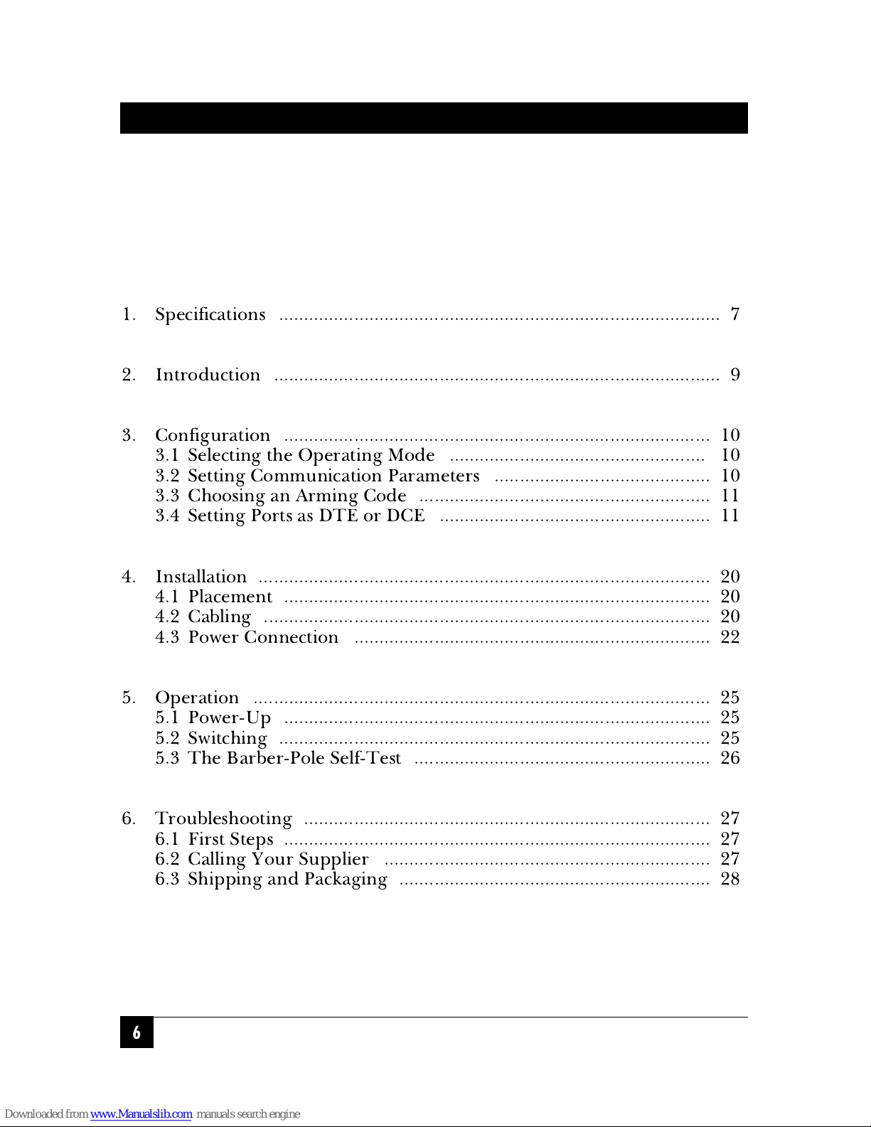
1. Specifications ........................................................................................ 7
2. Introduction ......................................................................................... 9
3. Configuration ..................................................................................... 10
3.1 Selecting the Operating Mode ................................................... 10
3.2 Setting Communication Parameters ........................................... 10
3.3 Choosing an Arming Code .......................................................... 11
3.4 Setting Ports as DTE or DCE ...................................................... 11
4. Installation .......................................................................................... 20
4.1 Placement ..................................................................................... 20
4.2 Cabling ......................................................................................... 20
4.3 Power Connection ....................................................................... 22
5. Operation ........................................................................................... 25
5.1 Power-Up ..................................................................................... 25
5.2 Switching ...................................................................................... 25
5.3 The Barber-Pole Self-Test ........................................................... 26
6. Troubleshooting ................................................................................. 27
6.1 First Steps ..................................................................................... 27
6.2 Calling Your Supplier ................................................................. 27
6.3 Shipping and Packaging .............................................................. 28
6
Page 6
7
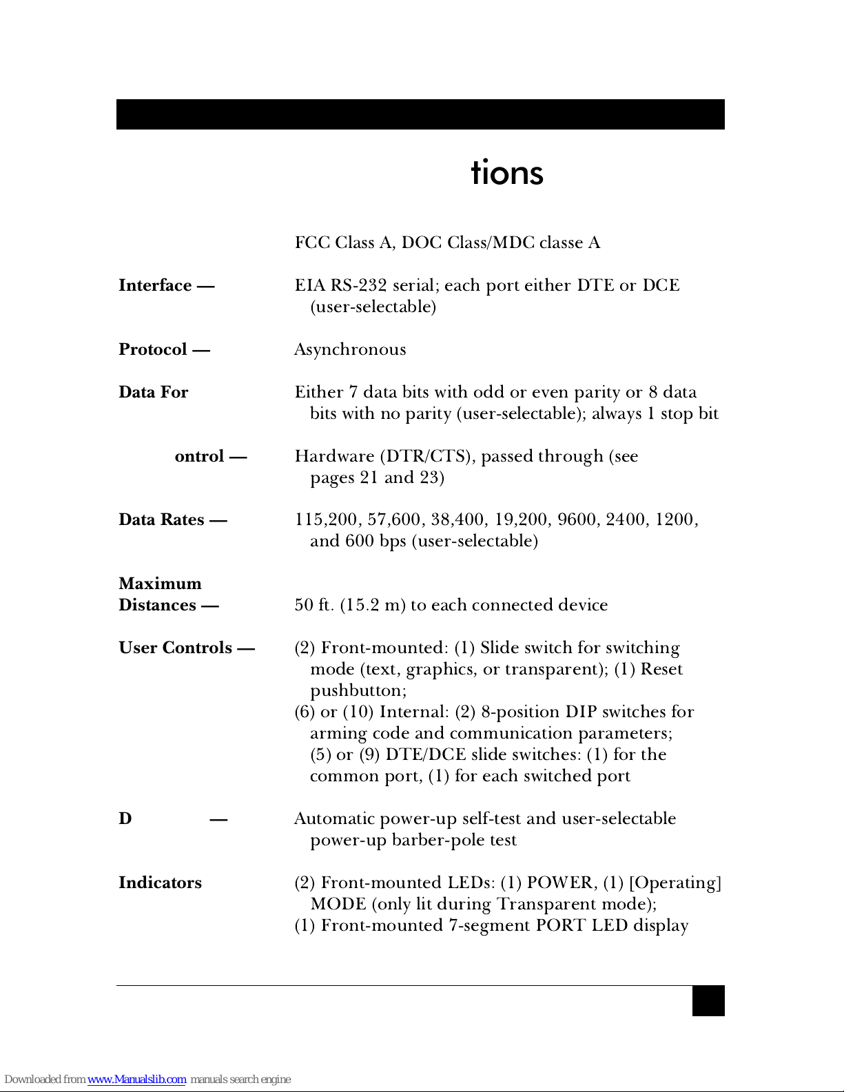
CHAPTER 1: Specifications
Compliance —
FCC Class A, DOC Class/MDC classe A
Interface —
EIA RS-232 serial; each port either DTE or DCE
(user-selectable)
Protocol —
Asynchronous
Data Format —
Either 7 data bits with odd or even parity or 8 data
bits with no parity (user-selectable); always 1 stop bit
Flow Control —
Hardware (DTR/CTS), passed through (see
pages 21 and 23)
Data Rates —
115,200, 57,600, 38,400, 19,200, 9600, 2400, 1200,
and 600 bps (user-selectable)
Maximum
Distances —
50 ft. (15.2 m) to each connected device
User Controls —
(2) Front-mounted: (1) Slide switch for switching
mode (text, graphics, or transparent); (1) Reset
pushbutton;
(6) or (10) Internal: (2) 8-position DIP switches for
arming code and communication parameters;
(5) or (9) DTE/DCE slide switches: (1) for the
common port, (1) for each switched port
Diagnostic —
Automatic power-up self-test and user-selectable
power-up barber-pole test
Indicators —
(2) Front-mounted LEDs: (1) POWER, (1) [Operating]
MODE (only lit during Transparent mode);
(1) Front-mounted 7-segment PORT LED display
1. Specifications
Page 7
8
HIGH SPEED COS-4 AND HIGH SPEED COS-8
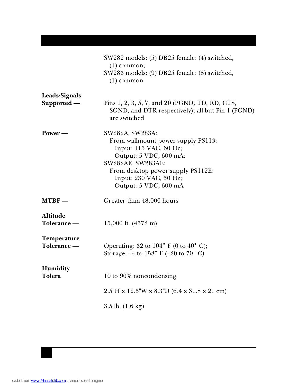
Connectors —
SW282 models: (5) DB25 female: (4) switched,
(1) common;
SW283 models: (9) DB25 female: (8) switched,
(1) common
Leads/Signals
Supported —
Pins 1, 2, 3, 5, 7, and 20 (PGND, TD, RD, CTS,
SGND, and DTR respectively); all but Pin 1 (PGND)
are switched
Power —
SW282A, SW283A:
From wallmount power supply PS113:
Input: 115 VAC, 60 Hz;
Output: 5 VDC, 600 mA;
SW282AE, SW283AE:
From desktop power supply PS112E:
Input: 230 VAC, 50 Hz;
Output: 5 VDC, 600 mA
MTBF —
Greater than 48,000 hours
Altitude
Tolerance —
15,000 ft. (4572 m)
Temperature
Tolerance —
Operating: 32 to 104˚ F (0 to 40˚ C);
Storage: –4 to 158˚ F (–20 to 70˚ C)
Humidity
Tolerance —
10 to 90% noncondensing
Size —
2.5"H x 12.5"W x 8.3"D (6.4 x 31.8 x 21 cm)
Weight —
3.5 lb. (1.6 kg)
Page 8
9
CHAPTER 2: Introduction
With the High Speed COS-4 or High Speed COS-8, you can send a code
sequence from an asynchronous RS-232 device and switch between four or
eight other such devices. By using this electronic method to switch, you
avoid the problems that can occur (especially with laser printers) when you
switch manually. You can select any two-byte sequence as the “arming code”
(the code that causes the COS to switch).
The High Speed COS-4 and COS-8 have three modes of operation, which
you can choose between with the slide switch on the front panel. In Text
mode, the user can send the chosen arming code, followed by the ASCII
character corresponding to the desired port (from “1” to “4” or “8,” or “0”
for no port, or “9” for all ports), immediately following other data. In
Graphics mode, the arming code and port character are not recognized
unless they are preceded by a pause. (You can select the length of this
pause.) In Transparent mode, arming codes are not recognized and
switching does not occur; arming codes will be passed through the COS
until it is set to a different mode.
2. Introduction
Page 9
10
HIGH SPEED COS-4 AND HIGH SPEED COS-8
Before you install the High Speed COS-4 or High Speed COS-8, you
should configure it for your application.
Section 3.1
describes setting the
front-panel Mode switch to select your desired operating mode.
Section 3.2
describes setting the internal DIP switch SW1 so that the COS operates
using the communication parameters that you need;
Section 3.3
describes
how to choose your arming code by setting the internal DIP switch SW2;
Section 3.4
describes how to use the internal slide switches to set each port
as DTE or DCE.
3.1 Selecting the Operating Mode
Use the slide switch labeled “TX GR TR” on the front of the High-Speed
COS-4 or COS-8 to select which operating mode you want the unit to start
in. In the left-hand (TX) position, the Text mode is selected; in the center
(GR) position, the Graphics mode is selected; in the right-hand (TR)
position, the Transparent mode is selected. In Text and Graphics modes,
the MODE LED is dark; in Transparent mode, the MODE LED is lit to
alert you that switching is diabled until you change modes. (See
Chapter 2
and
Section 5.2
for descriptions of these modes.)
3.2 Setting Communication Parameters
Making sure that the unit is unplugged and powered down, open the High
Speed COS-4 or COS-8 by unscrewing and removing six screws (three on the
left side of the unit, three on the right side), then removing the unit’s cover.
Use the DIP switch labeled SW11 inside the unit to set its communications
parameters. As shown in Table 3-1 on page 12, positions 1 through 3
control the data rate; positions 4 and 5 control the data format; and
positions 7 and 8 control the graphics-mode pause. (Use position 6 for
troubleshooting, when you want the COS to run its barber-pole self-test.)
For first-time configuration, leave the case open to choose the arming code
(see the next section) and set your ports for DTE or DCE (see
Section 3.4
).
3. Configuration
Page 10

11
CHAPTER 3: Configuration
3.3 Choosing the Arming Code
Use the DIP switch labeled SW12 inside the High-Speed COS-4 or COS-8
to set the COS’s “arming code” (the character that alerts the COS to an
impending switch). As shown in Table 3-2 on pages 13 through 19, each
possible setting of the eight DIP switch positions corresponds to a one-byte
character value from 00 to FF hex (0 to 255 decimal). For first-time
configuration, leave the case open to set your ports for DTE or DCE (see
the next section).
3.4 Setting Ports as DTE or DCE
Decide which devices you’re going to connect to which of the High Speed
COS-4’s or COS-8’s ports. Then set the DTE/DCE slide switches inside the
unit (there’s one just behind every port) so that you can use standard,
straight-through-pinned cables to attach the devices to the ports: If a device
is a DTE, set the port as DCE (move the switch to the B position); if a device
is a DCE, set the port as DTE (move the switch to the A position). Once
you’ve finished, replace the COS’s cover and secure it by screwing the
screws back in.
(Chapter 4, Installation, begins on page 20)
Page 11

12
HIGH SPEED COS-4 AND HIGH SPEED COS-8
Table 3-1. Possible Settings of the Communications DIP Switch*
FUNCTION DIP SWITCH POSITIONS
12345678
Data Rate (bps)
115,200 OFF OFF OFF
57,600 ON OFF OFF
38,400 OFF ON OFF
19,200† ON ON OFF
9600 OFF OFF ON
2400 ON OFF ON
1200 OFF ON ON
600 ON ON ON
Data Format
8 data bits, no parity† OFF OFF
8 data bits, no parity ON OFF
7 data bits, odd parity OFF ON
7 data bits, even parity ON ON
Operating Mode
Normal† OFF
Self-Test ON
Pause for Graphics Mode
1 millisecond† OFF OFF
10 milliseconds ON OFF
100 milliseconds OFF ON
500 milliseconds ON ON
*A switch position is ON when it is up (closer to the number that identifies it).
†Default setting.
Page 12

13
CHAPTER 3: Configuration
Table 3-2. Possible Settings of the Arming-Code DIP Switch*
ARMING CODE DIP SWITCH POSITIONS
HEX ASCII NAME 1 2 3 4 5 6 7 8
00 CTRL-@ NUL OFF OFF OFF OFF OFF OFF OFF OFF
01 CTRL-A SOH ON OFF OFF OFF OFF OFF OFF OFF
02 CTRL-B STX OFF ON OFF OFF OFF OFF OFF OFF
03 CTRL-C ETX ON ON OFF OFF OFF OFF OFF OFF
04†
CTRL-D EOT OFF OFF ON OFF OFF OFF OFF OFF
05 CTRL-E ENQ ON OFF ON OFF OFF OFF OFF OFF
06 CTRL-F ACK OFF ON ON OFF OFF OFF OFF OFF
07 CTRL-G BEL ON ON ON OFF OFF OFF OFF OFF
08 CTRL-H BS OFF OFF OFF ON OFF OFF OFF OFF
09 CTRL-I HT ON OFF OFF ON OFF OFF OFF OFF
0A CTRL-J LF OFF ON OFF ON OFF OFF OFF OFF
0B CTRL-K VT ON ON OFF ON OFF OFF OFF OFF
0C CTRL-L FF OFF OFF ON ON OFF OFF OFF OFF
0D CTRL-M CR ON OFF ON ON OFF OFF OFF OFF
0E CTRL-N SO OFF ON ON ON OFF OFF OFF OFF
0F CTRL-O Sl ON ON ON ON OFF OFF OFF OFF
10 CTRL-P DLE OFF OFF OFF OFF ON OFF OFF OFF
11 CTRL-Q DC1 ON OFF OFF OFF ON OFF OFF OFF
12 CTRL-R DC2 OFF ON OFF OFF ON OFF OFF OFF
13 CTRL-S DC3 ON ON OFF OFF ON OFF OFF OFF
14 CTRL-T DC4 OFF OFF ON OFF ON OFF OFF OFF
15 CTRL-U NAK ON OFF ON OFF ON OFF OFF OFF
16 CTRL-V SYN OFF ON ON OFF ON OFF OFF OFF
17 CTRL-W ETB ON ON ON OFF ON OFF OFF OFF
18 CTRL-X CAN OFF OFF OFF ON ON OFF OFF OFF
19 CTRL-Y EM ON OFF OFF ON ON OFF OFF OFF
1A CTRL-Z SUB OFF ON OFF ON ON OFF OFF OFF
1B CTRL-[ ESC ON ON OFF ON ON OFF OFF OFF
1C CTRL-\ FS OFF OFF ON ON ON OFF OFF OFF
1D CTRL-] GS ON OFF ON ON ON OFF OFF OFF
1E CTRL-^ RS OFF ON ON ON ON OFF OFF OFF
1F CTRL-_ US ON ON ON ON ON OFF OFF OFF
20 space SP OFF OFF OFF OFF OFF ON OFF OFF
*A switch position is ON when it is up (closer to the number that identifies it).
†Default setting.
Page 13

14
HIGH SPEED COS-4 AND HIGH SPEED COS-8
ARMING CODE DIP SWITCH POSITIONS
HEX ASCII 12345678
21 ! ON OFF OFF OFF OFF ON OFF OFF
22 " OFF ON OFF OFF OFF ON OFF OFF
23 # ON ON OFF OFF OFF ON OFF OFF
24 $ OFF OFF ON OFF OFF ON OFF OFF
25 % ON OFF ON OFF OFF ON OFF OFF
26 & OFF ON ON OFF OFF ON OFF OFF
27 ' ON ON ON OFF OFF ON OFF OFF
28 ( OFF OFF OFF ON OFF ON OFF OFF
29 ) ON OFF OFF ON OFF ON OFF OFF
2A * OFF ON OFF ON OFF ON OFF OFF
2B + ON ON OFF ON OFF ON OFF OFF
2C , OFF OFF ON ON OFF ON OFF OFF
2D - ON OFF ON ON OFF ON OFF OFF
2E . OFF ON ON ON OFF ON OFF OFF
2F / ON ON ON ON OFF ON OFF OFF
30 0 OFF OFF OFF OFF ON ON OFF OFF
31 1 ON OFF OFF OFF ON ON OFF OFF
32 2 OFF ON OFF OFF ON ON OFF OFF
33 3 ON ON OFF OFF ON ON OFF OFF
34 4 OFF OFF ON OFF ON ON OFF OFF
35 5 ON OFF ON OFF ON ON OFF OFF
36 6 OFF ON ON OFF ON ON OFF OFF
37 7 ON ON ON OFF ON ON OFF OFF
38 8 OFF OFF OFF ON ON ON OFF OFF
39 9 ON OFF OFF ON ON ON OFF OFF
3A : OFF ON OFF ON ON ON OFF OFF
3B ; ON ON OFF ON ON ON OFF OFF
3C < OFF OFF ON ON ON ON OFF OFF
3D = ON OFF ON ON ON ON OFF OFF
3E > OFF ON ON ON ON ON OFF OFF
3F? ONONONONONONOFFOFF
40 @ OFF OFF OFF OFF OFF OFF ON OFF
41 A ON OFF OFF OFF OFF OFF ON OFF
42 B OFF ON OFF OFF OFF OFF ON OFF
43 C ON ON OFF OFF OFF OFF ON OFF
44 D OFF OFF ON OFF OFF OFF ON OFF
45 E ON OFF ON OFF OFF OFF ON OFF
46 F OFF ON ON OFF OFF OFF ON OFF
47 G ON ON ON OFF OFF OFF ON OFF
Page 14

15
CHAPTER 3: Configuration
ARMING CODE DIP SWITCH POSITIONS
HEX ASCII 12345678
48 H OFF OFF OFF ON OFF OFF ON OFF
49 I ON OFF OFF ON OFF OFF ON OFF
4A J OFF ON OFF ON OFF OFF ON OFF
4B K ON ON OFF ON OFF OFF ON OFF
4C L OFF OFF ON ON OFF OFF ON OFF
4D M ON OFF ON ON OFF OFF ON OFF
4E N OFF ON ON ON OFF OFF ON OFF
4F O ON ON ON ON OFF OFF ON OFF
50 P OFF OFF OFF OFF ON OFF ON OFF
51 Q ON OFF OFF OFF ON OFF ON OFF
52 R OFF ON OFF OFF ON OFF ON OFF
53 S ON ON OFF OFF ON OFF ON OFF
54 T OFF OFF ON OFF ON OFF ON OFF
55 U ON OFF ON OFF ON OFF ON OFF
56 V OFF ON ON OFF ON OFF ON OFF
57 W ON ON ON OFF ON OFF ON OFF
58 X OFF OFF OFF ON ON OFF ON OFF
59 Y ON OFF OFF ON ON OFF ON OFF
5A Z OFF ON OFF ON ON OFF ON OFF
5B [ ON ON OFF ON ON OFF ON OFF
5C \ OFF OFF ON ON ON OFF ON OFF
5D ] ON OFF ON ON ON OFF ON OFF
5E ^ OFF ON ON ON ON OFF ON OFF
5F _ ON ON ON ON ON OFF ON OFF
60 ` OFF OFF OFF OFF OFF ON ON OFF
61 a ON OFF OFF OFF OFF ON ON OFF
62 b OFF ON OFF OFF OFF ON ON OFF
63 c ON ON OFF OFF OFF ON ON OFF
64 d OFF OFF ON OFF OFF ON ON OFF
65 e ON OFF ON OFF OFF ON ON OFF
66 f OFF ON ON OFF OFF ON ON OFF
67
g ON ON ON OFF OFF ON ON OFF
68 h OFF OFF OFF ON OFF ON ON OFF
69 i ON OFF OFF ON OFF ON ON OFF
6A j OFF ON OFF ON OFF ON ON OFF
6B k ON ON OFF ON OFF ON ON OFF
6C I OFF OFF ON ON OFF ON ON OFF
6D m ON OFF ON ON OFF ON ON OFF
6E n OFF ON ON ON OFF ON ON OFF
Page 15

16
HIGH SPEED COS-4 AND HIGH SPEED COS-8
ARMING CODE DIP SWITCH POSITIONS
HEX ASCII 12345678
6F o ON ON ON ON OFF ON ON OFF
70 p OFF OFF OFF OFF ON ON ON OFF
71 q ON OFF OFF OFF ON ON ON OFF
72 r OFF ON OFF OFF ON ON ON OFF
73 s ON ON OFF OFF ON ON ON OFF
74 t OFF OFF ON OFF ON ON ON OFF
75 u ON OFF ON OFF ON ON ON OFF
76 v OFF ON ON OFF ON ON ON OFF
77 w ON ON ON OFF ON ON ON OFF
78 x OFF OFF OFF ON ON ON ON OFF
79 y ON OFF OFF ON ON ON ON OFF
7A z OFF ON OFF ON ON ON ON OFF
7B { ON ON OFF ON ON ON ON OFF
7C I OFF OFF ON ON ON ON ON OFF
7D } ON OFF ON ON ON ON ON OFF
7E ~ OFF ON ON ON ON ON ON OFF
7F DEL ON ON ON ON ON ON ON OFF
80 OFF OFF OFF OFF OFF OFF OFF ON
81 ON OFF OFF OFF OFF OFF OFF ON
82 OFF ON OFF OFF OFF OFF OFF ON
83 ON ON OFF OFF OFF OFF OFF ON
84 OFF OFF ON OFF OFF OFF OFF ON
85 ON OFF ON OFF OFF OFF OFF ON
86 OFF ON ON OFF OFF OFF OFF ON
87 ON ON ON OFF OFF OFF OFF ON
88 OFF OFF OFF ON OFF OFF OFF ON
89 ON OFF OFF ON OFF OFF OFF ON
8A OFF ON OFF ON OFF OFF OFF ON
8B ON ON OFF ON OFF OFF OFF ON
8C OFF OFF ON ON OFF OFF OFF ON
8D ON OFF ON ON OFF OFF OFF ON
8E OFF ON ON ON OFF OFF OFF ON
8F ON ON ON ON OFF OFF OFF ON
90 OFF OFF OFF OFF ON OFF OFF ON
91 ON OFF OFF OFF ON OFF OFF ON
92 OFF ON OFF OFF ON OFF OFF ON
93 ON ON OFF OFF ON OFF OFF ON
94 OFF OFF ON OFF ON OFF OFF ON
95 ON OFF ON OFF ON OFF OFF ON
Page 16

17
CHAPTER 3: Configuration
ARMING CODE DIP SWITCH POSITIONS
HEX ASCII 12345678
96 OFF ON ON OFF ON OFF OFF ON
97 ON ON ON OFF ON OFF OFF ON
98 OFF OFF OFF ON ON OFF OFF ON
99 ON OFF OFF ON ON OFF OFF ON
9A OFF ON OFF ON ON OFF OFF ON
9B ON ON OFF ON ON OFF OFF ON
9C OFF OFF ON ON ON OFF OFF ON
9D ON OFF ON ON ON OFF OFF ON
9E OFF ON ON ON ON OFF OFF ON
9F ON ON ON ON ON OFF OFF ON
A0 OFF OFF OFF OFF OFF ON OFF ON
A1 ON OFF OFF OFF OFF ON OFF ON
A2 OFF ON OFF OFF OFF ON OFF ON
A3 ON ON OFF OFF OFF ON OFF ON
A4 OFF OFF ON OFF OFF ON OFF ON
A5 ON OFF ON OFF OFF ON OFF ON
A6 OFF ON ON OFF OFF ON OFF ON
A7 ON ON ON OFF OFF ON OFF ON
A8 OFF OFF OFF ON OFF ON OFF ON
A9 ON OFF OFF ON OFF ON OFF ON
AA OFF ON OFF ON OFF ON OFF ON
AB ON ON OFF ON OFF ON OFF ON
AC OFF OFF ON ON OFF ON OFF ON
AD ON OFF ON ON OFF ON OFF ON
AE OFF ON ON ON OFF ON OFF ON
AF ON ON ON ON OFF ON OFF ON
B0 OFF OFF OFF OFF ON ON OFF ON
B1 ON OFF OFF OFF ON ON OFF ON
B2 OFF ON OFF OFF ON ON OFF ON
B3 ON ON OFF OFF ON ON OFF ON
B4 OFF OFF ON OFF ON ON OFF ON
B5 ON OFF ON OFF ON ON OFF ON
B6 OFF ON ON OFF ON ON OFF ON
B7 ON ON ON OFF ON ON OFF ON
B8 OFF OFF OFF ON ON ON OFF ON
B9 ON OFF OFF ON ON ON OFF ON
BA OFF ON OFF ON ON ON OFF ON
BB ON ON OFF ON ON ON OFF ON
BC OFF OFF ON ON ON ON OFF ON
Page 17

18
HIGH SPEED COS-4 AND HIGH SPEED COS-8
ARMING CODE DIP SWITCH POSITIONS
HEX ASCII 12345678
BD ON OFF ON ON ON ON OFF ON
BE OFF ON ON ON ON ON OFF ON
BF ON ON ON ON ON ON OFF ON
C0 OFF OFF OFF OFF OFF OFF ON ON
C1 ON OFF OFF OFF OFF OFF ON ON
C2 OFF ON OFF OFF OFF OFF ON ON
C3 ON ON OFF OFF OFF OFF ON ON
C4 OFF OFF ON OFF OFF OFF ON ON
C5 ON OFF ON OFF OFF OFF ON ON
C6 OFF ON ON OFF OFF OFF ON ON
C7 ON ON ON OFF OFF OFF ON ON
C8 OFF OFF OFF ON OFF OFF ON ON
C9 ON OFF OFF ON OFF OFF ON ON
CA OFF ON OFF ON OFF OFF ON ON
CB ON ON OFF ON OFF OFF ON ON
CC OFF OFF ON ON OFF OFF ON ON
CD ON OFF ON ON OFF OFF ON ON
CE OFF ON ON ON OFF OFF ON ON
CF ON ON ON ON OFF OFF ON ON
D0 OFF OFF OFF OFF ON OFF ON ON
D1 ON OFF OFF OFF ON OFF ON ON
D2 OFF ON OFF OFF ON OFF ON ON
D3 ON ON OFF OFF ON OFF ON ON
D4 OFF OFF ON OFF ON OFF ON ON
D5 ON OFF ON OFF ON OFF ON ON
D6 OFF ON ON OFF ON OFF ON ON
D7 ON ON ON OFF ON OFF ON ON
D8 OFF OFF OFF ON ON OFF ON ON
D9 ON OFF OFF ON ON OFF ON ON
DA OFF ON OFF ON ON OFF ON ON
DB ON ON OFF ON ON OFF ON ON
DC OFF OFF ON ON ON OFF ON ON
DD ON OFF ON ON ON OFF ON ON
DE OFF ON ON ON ON OFF ON ON
DF ON ON ON ON ON OFF ON ON
E0 OFF OFF OFF OFF OFF ON ON ON
E1 ON OFF OFF OFF OFF ON ON ON
E2 OFF ON OFF OFF OFF ON ON ON
E3 ON ON OFF OFF OFF ON ON ON
Page 18

19
CHAPTER 3: Configuration
ARMING CODE DIP SWITCH POSITIONS
HEX ASCII 12345678
E4 OFF OFF ON OFF OFF ON ON ON
E5 ON OFF ON OFF OFF ON ON ON
E6 OFF ON ON OFF OFF ON ON ON
E7 ON ON ON OFF OFF ON ON ON
E8 OFF OFF OFF ON OFF ON ON ON
E9 ON OFF OFF ON OFF ON ON ON
EA OFF ON OFF ON OFF ON ON ON
EB ON ON OFF ON OFF ON ON ON
EC OFF OFF ON ON OFF ON ON ON
ED ON OFF ON ON OFF ON ON ON
EE OFF ON ON ON OFF ON ON ON
EF ON ON ON ON OFF ON ON ON
F0 OFF OFF OFF OFF ON ON ON ON
F1 ON OFF OFF OFF ON ON ON ON
F2 OFF ON OFF OFF ON ON ON ON
F3 ON ON OFF OFF ON ON ON ON
F4 OFF OFF ON OFF ON ON ON ON
F5 ON OFF ON OFF ON ON ON ON
F6 OFF ON ON OFF ON ON ON ON
F7 ON ON ON OFF ON ON ON ON
F8 OFF OFF OFF ON ON ON ON ON
F9 ON OFF OFF ON ON ON ON ON
FA OFF ON OFF ON ON ON ON ON
FB ON ON OFF ON ON ON ON ON
FC OFF OFF ON ON ON ON ON ON
FD ON OFF ON ON ON ON ON ON
FE OFF ON ON ON ON ON ON ON
FF ON ON ON ON ON ON ON ON
Page 19

20
HIGH SPEED COS-4 AND HIGH SPEED COS-8
4.1 Placement
Place the High Speed COS-4 or High-Speed COS-8 in a cool, dry place
close to an electrical outlet. It should be within 50 ft. (15.2 m) of the devices
you want to connect to it.
NOTE
The High Speed COS-4 and COS-8 can be mounted in a standard 19"
equipment rack with a rackmount adapter kit. The kit is not included with
the unit; call your supplier for a special quote.
4.2 Cabling
This section describes the cables and procedures you’ll use to connect
equipment to the High Speed COS-4 or COS-8. Refer to Figure 4-1 on
page 24 for an illustration of a typical application.
4.2.1 C
OMPUTER(S
)↔COS
For each computer you want to connect to the High Speed COS-4 or
COS-8, you’ll need a cable containing at least 5 wires with a DB25 male
connector on the COS end. If a computer is an IBM®AT®or PS/2®or
compatible, the cable should have a DB9 female connector on the computer
end. If a computer is an IBM PC/XT™ or compatible, the cable should have
a DB25 female connector on the computer end. Assuming you’ve set the
COS port(s) as DCE (see
Section 3.4
), the cable(s) should be wired as shown
in Tables 4-1 and 4-2 on the next page. (Our product codes for cables
pinned this way are EVMBMC for the DB9 type and ECM12C for the
DB25 type.)
Connect the female end of each of these cables to the serial port (COM1,
COM2, etc.) on the selected computer. If the selected computer is the
“source” or “master” (the one that’s doing the switching), connect the male
end of the cable to the COS’s common port (Port 0). If the computer is a
“destination” or “slave” (one that’s being switched between), connect the
male end of the cable to the chosen numbered port on the COS.
4. Installation
Page 20

21
CHAPTER 4: Installation
Table 4-1. Pinning, AT Computer to COS (EVMBMC Cable*)
Computer COS as DCE
DB9 DB25
RD 2 ----------------------------------- 3 TD
TD 3 ----------------------------------- 2 RD
DTR† 4 ----------------------------------- 20 DTR†
SGND 5 ----------------------------------- 7 SGND
CTS† 8 ----------------------------------- 5 CTS†
Table 4-2. Pinning, PC/XT Computer or Serial Printer to COS
(ECM12C Cable**)
Computer COS as DCE
DB25 DB25
TD 2 ----------------------------------- 2 RD
RD 3 ----------------------------------- 3 TD
CTS† 5 ----------------------------------- 5 CTS†
SGND 7 ----------------------------------- 7 SGND
DTR† 20 ----------------------------------- 20 DTR†
*Our EVNBMC cable is pinned this way. It also carries the other pins supported by
the AT serial interface, but the High Speed COS-4 and COS-8 don’t support any of
the other pins except Pin 1, PGND, which is not required.
†When a device attached to the COS raises its flow-control lead, the COS sends the
appropriate flow-control signal to the device on the other end of the connection. For
example, suppose an administrator PC on Port 0 is communicating with a user PC on
Port 4. Both PCs are DTEs, so both ports are set as DCE. When the PC on Port 0
raises DTR, the COS raises CTS on Port 4; and when the PC on Port 4 raises DTR,
the COS raises CTS on Port 0. On the other hand, if the device on Port 4 is a mux (a
DCE, so that Port 4 is set as DTE), then when the PC on Port 0 raises DTR, the COS
raises DTR on Port 4; and when the mux on Port 4 raises CTS, the COS raises CTS
on Port 0.
**
Our ECM12C cable is pinnned this way. It also carries Pin 1, PGND, which the High
Speed COS-4 and COS-8 support but doesn’t require, as well as Pins 4, 6, 8, 15, 17,
and 22 (RTS, DSR, RLSD [DCD], TSETC [TC], RSET [RC], and RI respectively),
which the COSes don’t support at all.
Page 21

22
HIGH SPEED COS-4 AND HIGH SPEED COS-8
4.2.2 COS TOS
ERIALPRINTER(S
)
For each serial printer you want to connect to the High Speed COS-4 or
COS-8, you’ll need a cable containing at least 5 wires with DB25 male
connectors on each end. Assuming you’ve set the COS port(s) as DCE (see
Section 3.4
), the cable(s) should be wired as shown in Table 4-2 on the
previous page. (Our product code for a cable pinned this way is ECM12C.)
Connect one end of each of these cables to the input port on the selected
printer. Connect the other end to the chosen numbered port on the COS.
4.2.3 M
ODEM(S
)↔COS
We do not recommend attaching modems to the High Speed COS-4 or
COS-8, because the COSes don’t support Pin 4 (RTS), 6 (DSR), 8 (RLSD
[DCD]), or 22 (RI). When other involved devices (especially PCs running
terminal-emulation software) can’t see these pins/signals (especially Pins 8
and 22), most applications involving modems will not function correctly.
However, if the device(s) on the other side of the COS don’t need to see
any of these non-supported pins, you can attach one or more modems to
the COS, using cables containing at least 5 wires with DB25 male connectors
on each end. Assuming you’ve set the COS port(s) as DTE (see
Section 3.4
),
the cable(s) should be wired as shown in Table 4-3 on the next page. (Our
product code for a cable pinned this way is ECM12C.)
Connect one end of each of these cables to the input port on the selected
modem. If the selected modem is the “source” or “master” (the one that’s doing
the switching), connect the other end of the cable to the COS’s common
port (Port 0). If the modem is a “destination” or “slave” (one that’s being
switched between), connect the other end of the cable to the chosen
numbered port on the COS.
Some other DCEs, including some multiplexors, line drivers, and short-
haul modems, can function with only Pins 2, 3, 5, 7, and 20. You can attach
them to the COS as described in the previous two paragraphs.
Page 22

23
CHAPTER 4: Operation
Table 4-3. Pinning, Modem to COS (ECM12C Cable*)
Modem COS as DTE
DB25 DB25
RD 2 ----------------------------------- 2 TD
TD 3 ----------------------------------- 3 RD
CTS† 5 ----------------------------------- 5 CTS†
SGND 7 ----------------------------------- 7 SGND
DTR† 20 ----------------------------------- 20 DTR†
*Our ECM12C cable is pinnned this way. It also carries Pin 1, PGND, which the High
Speed COS-4 and COS-8 support but doesn’t require, as well as Pins 4, 6, 8, 15, 17,
and 22 (RTS, DSR, RLSD [DCD], TSETC [TC], RSET [RC], and RI respectively),
which the COSes don’t support at all.
††When a device attached to the COS raises its flow-control lead, the COS sends
the appropriate flow-control signal to the device on the other end of the connection.
For example, suppose a line driver on Port 0 is communicating with a mux on Port 4.
Both the driver and the mux are DCEs, so both ports are set as DTE. When the line
driver on Port 0 raises CTS, the COS raises DTR on Port 4; and when the mux on
Port 4 raises CTS, the COS raises DTR on Port 0. On the other hand, if the device
on Port 4 is a PC (a DTE, so that Port 4 is set as DCE), then when the line driver on
Port 0 raises CTS, the COS raises CTS on Port 4; and when the PC on Port 4 raises
DTR, the COS raises DTR on Port 0.
Page 23

24
HIGH SPEED COS-4 AND HIGH SPEED COS-8
Figure 4-1. A computer switching between four serial printers and
two modems through the High Speed COS-8.
Computer
Serial Line
Printers
Serial Laser
Printers
Modems
RS-232 cables
(ECM12C)
High Speed
COS-8
(SW283A)
4.3 Power Connection
NOTE
The input voltage and frequency requirements of the included powersupply adapter (identified on the transformer’s label) probably match the
voltage and frequency output by your local electric utility, but check just
to make sure.
Lastly,
when you are ready for the unit to start operating
, plug the output cord of
the High Speed COS-4’s or COS-8’s power-supply adapter into the power
socket (barrel jack) on the COS, then plug the adapter into a working outlet.
The unit will power up
immediately
—it has no ON/OFF switch—and will
perform a quick self-test. Digits 0 through 9 will appear in the 7-segment
display as the COS tests its internal circuitry, and then the display will show
“1” as the unit establishes a default connection between Port 0 (the master
port) and Port 1.
Your High Speed COS-4 or COS-8 is now ready for continuous operation.
Page 24

25
CHAPTER 5: Operation
5.1 Power-Up
As soon as you provide power to the High-Speed COS-4 or High Speed
COS-8 (see
Section 4.3
), the unit will power up (“turn on”), make its default
connection to Port 1, and perform its minimal self-test. If position 6 of DIP
switch SW1 inside the COS is set to OFF (down), the COS will be ready to
operate normally. If position 6 is set to ON (up), the COS will begin
sending its barber-pole self-test (see
Section 5.3
) out of Port 1.
5.2 Switching
At any time, you can switch which port (and which attached “slave” or
“destination” device) your “master” device (the one on the common port)
has access to. Do this by sending the currently active arming code (see
Section 3.3
), followed by the character correpsonding to the number of the
desired port (“1” through “4” for the High Speed COS-4 or “1” through “8”
for the High Speed COS-8), from the master device.
You can also connect the master to all slaves (to send “broadcast” data to
all ports) by sending the arming code followed by the number “9”. While
the COS is in this setting, however, there is no flow control or port
contention among the slaves, and if more than one of them sends data at
the same time, it will become hopelessly intermixed and garbled.
Finally, you can disconnect the master
from all slaves by sending the
arming code followed by the number “0” (zero). While the COS is in this
setting, no data sent by any attached device will be passed to any other device.
The COS-4 and COS-8 have three switching modes: Text, Graphics, and
Transparent. While the COS’s front-panel “Mode” switch is in the TX
(Text, left-hand) position, the COS operates in Text mode: The arming
code and port character are recognized without a preceding pause. While
the COS is in Text mode, its MODE LED is dark.
If you are using Text mode and you find that unwanted switching is
occurring, move the COS’s front-panel Mode switch to the GR (Graphics,
center) position. In Graphics mode, a pause must occur before the arming
code is recognized, so incidental occurrences of the arming code and the
port character among data do not cause the COS to switch as readily. While
the COS is in Graphics mode, its MODE LED is dark.
5. Operation
Page 25

26
HIGH SPEED COS-4 AND HIGH SPEED COS-8
If unwanted switching continues to occur, try lengthening the graphics-
mode pause. (This is the period of time that must elapse
after
the COS stops
receiving data in Graphics mode
before
it will recognize the arming code if it
receives it.) Lengthen the pause by setting positions 7 and 8 of the COS’s
DIP switch SW1 differently (see
Section 3.2
).
If you need to temporarily disable switching for some reason (for
example, if you know there will be delays longer than 500 milliseconds
during the transmission of a graphics file), you can move the COS’s Mode
switch to the TR (Transparent, right-hand) position. While the COS is in
Transparent mode, the arming code is ignored, and the MODE LED is lit
to remind you that switching is impossible until you change modes.
5.3 The Barber-Pole Self-Test
To have the High Speed COS-4 or COS-8 perform a self-test of its
transmission circuitry, unplug it, open it up as described in
Section 3.2
, and
set position 6 of its DIP switch SW1 to ON (up). Connect Port 1 to a
terminal or other RS-232 device whose data rate and data format match
those selected on the COS. Close the COS and turn it back on: The COS
will begin outputting the following items to the RS-232 device connected to
Port 1
only
:
• The COS’s EPROM version; then
• The current settings of switches SW1 and SW2; then
• A continuous “barber pole” pattern of ASCII characters.
To end the test and return to normal operation, take these steps:
1. Turn the COS off again;
2. If necessary, disconnect the RS-232 device from Port 1 and reconnect
the original equipment;
3. Reopen the COS;
4. Set position 6 of the COS’s DIP switch SW1 to OFF (down);
5. Reclose the COS (and make sure to screw the case back on securely);
and
6. Turn the COS back on again.
Page 26

27
CHAPTER 5: Operation
6.1 First Steps
If your High Speed COS-4 or High Speed COS-8 does not seem to be
passing data or switching correctly, the first thing to try is to have the COS
perform its barber-pole self-test as described in
Section 5.3
. If the data that
the COS is transmitting looks OK, check the settings of its front-panel Mode
switch and its internal DIP switches and make sure these are correct. If they
are, check the cables connected to the COS and make sure all of them are
securely connected to the proper equipment at both ends. If the cabling is
OK, turn the printer(s) off and back on and try again. If problems persist,
reboot the computer(s) (saving any documents in progress first), reload the
software you were using and the affected document(s), and try again. If you
still have problems, contact your supplier.
6.2 Calling Your Supplier
If you determine that your High Speed COS-4 or COS-8 is malfunctioning,
do not attempt to alter or repair it.
Contact your supplier. The problem might
be solvable over the phone.
Before you do, make a record of the history of the problem. Your
supplier will be able to provide more efficient and accurate assistance if you
have a complete description, including:
• The nature and duration of the problem.
• When the problem occurs.
• The components involved in the problem.
• Any particular application that, when used, appears to create the
problem or make it worse.
6. Troubleshooting
Page 27

28
HIGH SPEED COS-4 AND HIGH SPEED COS-8
6.3 Shipping and Packaging
If you need to transport or ship your High Speed COS-4 or COS-8:
• Package it carefully. We recommend that you use the original container.
• Before you ship a unit for repair or return, contact your supplier to get
a Return Materials Authorization (RMA) number, and make sure you
include everything you received with the unit when you ship it.
Page 28

NOTES
Page 29

NOTES
Page 30

CUSTOMER
SUPPORT
INFORMATION
To order or for technical support: Call 724-746-5500 or fax 724-746-0746
Technical support and fax orders 24 hours a day, 7 days a week
Phone orders 24 hours, 7 A.M. Monday to midnight Friday; Saturday 8 to 4 (Eastern)
Mail order: Black Box Corporation, 1000 Park Drive, Lawrence, PA 15055-1018
APRIL 1998
SW282A
SW282AE
SW283A
SW283AE
High Speed COS-4
High Speed COS-8
PO
W
ER
M
O
D
E
R
ES
ET
TX G
R
TR
PO
R
T
HIGH SPEED COS-8
 Loading...