

Page 1
CUSTOMER
SUPPORT
INFORMATION
SEPTEMBER 1995
CMA02A
CMA02C
Communications Adapter Plus (CAP)
Order toll-free in the U.S. 24 hours, 7 A.M. Monday to midnight Friday: 877-877-BBOX
FREE technical support, 24 hours a day, 7 days a week: Call 724-746-5500 or fax 724-746-0746
Mail order: Black Box Corporation, 1000 Park Drive, Lawrence, PA 15055-1018
Web site: www.blackbox.com • E-mail: info@blackbox.com
CAP
RESET
TXA RXA TXB RXB PWR
Page 2

FEDERAL COMMUNICATIONS COMMISSION
AND
CANADIAN DEPARTMENT OF COMMUNICATIONS
RADIO FREQUENCY INTERFERENCE STATEMENTS
This equipment generates, uses, and can radiate radio frequency energy and if not installed and used properly, that is, in
strict accordance with the manufacturer’s instructions, may cause interference to radio communication. It has been tested
and found to comply with the limits for a Class A computing device in accordance with the specifications in Subpart J of
Part 15 of FCC rules, which are designed to provide reasonable protection against such interference when the equipment is
operated in a commercial environment. Operation of this equipment in a residential area is likely to cause interference, in
which case the user at his own expense will be required to take whatever measures may be necessary to correct the
interference.
Changes or modifications not expressly approved by the party responsible for compliance could void the user’s authority to
operate the equipment.
This digital apparatus does not exceed the Class A limits for radio noise emission from digital apparatus set out in the Radio Interference
Regulation of the Canadian Department of Communications.
Le présent appareil numérique n’émet pas de bruits radioélectriques dépassant les limites applicables aux appareils numériques de
classe A prescrites dans le Règlement sur le brouillage radioélectrique publié par le ministère des Communications du Canada.
INSTRUCCIONES DE SEGURIDAD (Normas Oficiales Mexicanas Electrical Safety Statement)
1. Todas las instrucciones de seguridad y operación
deberán ser leídas antes de que el aparato eléctrico sea
operado.
2. Las instrucciones de seguridad y operación deberán ser
guardadas para referencia futura.
3. Todas las advertencias en el aparato eléctrico y en sus
instrucciones de operación deben ser respetadas.
4. Todas las instrucciones de operación y uso deben ser
seguidas.
5. El aparato eléctrico no deberá ser usado cerca del
agua—por ejemplo, cerca de la tina de baño, lavabo,
sótano mojado o cerca de una alberca, etc..
6. El aparato eléctrico debe ser usado únicamente con
carritos o pedestales que sean recomendados por el
fabricante.
7. El aparato eléctrico debe ser montado a la pared o al
techo sólo como sea recomendado por el fabricante.
8. Servicio—El usuario no debe intentar dar servicio al
equipo eléctrico más allá a lo descrito en las
instrucciones de operación. Todo otro servicio deberá
ser referido a personal de servicio calificado.
9. El aparato eléctrico debe ser situado de tal manera que
su posición no interfiera su uso. La colocación del
aparato eléctrico sobre una cama, sofá, alfombra o
superficie similar puede bloquea la ventilación, no se
debe colocar en libreros o gabinetes que impidan el
flujo de aire por los orificios de ventilación.
10. El equipo eléctrico deber ser situado fuera del alcance
de fuentes de calor como radiadores, registros de calor,
estufas u otros aparatos (incluyendo amplificadores)
que producen calor.
11. El aparato eléctrico deberá ser connectado a una
fuente de poder sólo del tipo descrito en el instructivo
de operación, o como se indique en el aparato.
12. Precaución debe ser tomada de tal manera que la tierra
fisica y la polarización del equipo no sea eliminada.
13. Los cables de la fuente de poder deben ser guiados de
tal manera que no sean pisados ni pellizcados por
objetos colocados sobre o contra ellos, poniendo
particular atención a los contactos y receptáculos
donde salen del aparato.
14. El equipo eléctrico debe ser limpiado únicamente de
acuerdo a las recomendaciones del fabricante.
15. En caso de existir, una antena externa deberá ser
localizada lejos de las lineas de energia.
16. El cable de corriente deberá ser desconectado del
cuando el equipo no sea usado por un largo periodo de
tiempo.
17. Cuidado debe ser tomado de tal manera que objectos
liquidos no sean derramados sobre la cubierta u
orificios de ventilación.
18. Servicio por personal calificado deberá ser provisto
cuando:
A: El cable de poder o el contacto ha sido dañado; u
B: Objectos han caído o líquido ha sido derramado
dentro del aparato; o
C: El aparato ha sido expuesto a la lluvia; o
D: El aparato parece no operar normalmente o
muestra un cambio en su desempeño; o
E: El aparato ha sido tirado o su cubierta ha sido
dañada.
Page 3

COMMUNICATIONS ADAPTER PLUS (CAP)
2
CONTENTS
1.0 SPECIFICATIONS.....................................................................................................................................3
2.0 INTRODUCTION.....................................................................................................................................4
2.1 Conversions Possible with the CAP ...............................................................................................4
3.0 INSTALLATION ......................................................................................................................................6
3.1 Installation Checklist......................................................................................................................6
3.2 Installing the CAP...........................................................................................................................7
3.2.1 AC Power............................................................................................................................7
3.2.2 Cable Requirements..........................................................................................................7
3.3 DIP Switch Settings.........................................................................................................................8
3.4 Setting the Mark and Space Parity ..............................................................................................10
3.5 CAP to Device Connection ..........................................................................................................14
4.0 TROUBLESHOOTING ..........................................................................................................................15
4.1 Diagnostic LEDs ...........................................................................................................................15
4.2 Cables and Configuration............................................................................................................15
5.0 CODE-SET CONVERSION TABLES .....................................................................................................16
5.1 Lower-Case Letters .......................................................................................................................16
5.2 Upper-Case Letters.......................................................................................................................17
5.3 Numbers........................................................................................................................................17
5.4 Special Printable Characters........................................................................................................18
5.5 Control Codes...............................................................................................................................19
5.6 Ticker Tape...................................................................................................................................20
APPENDIX: OPTIONAL CABLES...............................................................................................................22
TRADEMARKS
AT
®
is a registered trademark of International Business Machines Corporation.
Any other trademarks mentioned in this manual are acknowledged to be the property of the trademarks
owners.
Page 4

CHAPTER 1: Specifications
3
Protocol — Asynchronous only
Speed — 45.5 bps to 38.4 Kbps
Flow Control — Hardware, X-ON/X-OFF, ENQ/ACK
Indicators — RXD and TXD for Ports A and B; Power
Interface — RS-232/CCITT V.24 configured as DTE
Connectors — (2) DB9 female
Processor — Z-80 CPU
Memory — 32K RAM
Controls — Reset
Environment — Operating Temperature: 32° to 113° F (0° to 45° C)
Storage Temperature -44° to 158° F (-20° to 70° C)
Humidity: 0 to 95% noncondensing
MTBF — 58,000 hours for a ground-benign environment
Enclosure — High-impact plastic
Power — 115 VAC, 50-60 Hz, 95 mA, 11 watts, or 230 VAC, 50-60 Hz, 48 mA, 11 watts
Size — 1.8"H x 5.5"W x 8.5"D (4.6 x 14.0 x 21.6 cm)
Shipping Weight — 2 lb. (0.9 kg)
Card Rack Specifications
Rack Size — 5.2"H x 19"W x 9.3"D (13.2 x 48.3 x 23.6 cm)
Card Size— 0.8"H x 4"W x 8.1"D (2 x 10.2 x 20.1 cm)
Weight — 9.5 lb (4.3 kg), without cards
Rack Power
Supply Specs — Primary: 115 VAC/60 Hz model or 230 VAC/50 Hz model
Output: 16 volts center-tap AC, 3.125 Amps
1 Specifications
Page 5

COMMUNICATIONS ADAPTER PLUS (CAP)
4
The Communications Adapter Plus (CAP) lets two
incompatible devices that use RS-232 interfaces
communicate with each other. The CAP is
programmed for your application through internal
DIP switches and jumpers. The CAP's 32K of RAM
can be allocated in different amounts for each port.
Below is a list of optional equipment you can use to
integrate the CAP into your application. See
Appendix A for the pinouts of the listed cables.
• Card Rack (RM010—CAP)
• Power Supply (PS154)
• Cables:
CAP-to DTE Cable (EHN023)
CAP-to-Modem Cable (EHN024)
CAP-to-AT Cable (EHN025)
Straight 9-Pin Cable (ECN12D*)
CAP-to-PC Cable (EHN026)
*Specify gender and length.
2.1 Conversions Possible with the CAP
The CAP can convert between two devices for any of
the following parameters:
• Word Structure — Defines the structure of the
asynchronous characters transmitted and
received over the RS-232C interface. The CAP's
communication ports can be set individually for
your devices' word structure.
CAP Word Structure Options:
a) 5, 6, 7, or 8 Data Bits
b) Even, Odd, or No Parity Bit (in some cases
Mark and Space)
c) 1, 1.5, or 2 Stop Bits
• Buffer Flow Control — The CAP can provide
the protocol for stopping and starting data
transfer between two devices.
CAP Buffer Flow Control Options:
1. Hardware Flow Control — A pin of the
RS-232 interface in used for buffer flow
control. If the pin being monitored by the
sending device is +12 V, the device can
transmit data. If the pin is -12 V, the device
cannot transmit data. A device attached to
the CAP is asked to stop transmitting when
only 256 bytes of unused space remain in
the buffer. The CAP permits the device
to transmit again when 512 bytes of
unused space remain in the buffer. It
will source DTR (Pin 20) and monitor
CTS (Pin 5).
2. ENQ/ACK Flow Control — Some devices
request permission to transmit a block of
asynchronous data by sending an "ENQ"
control code (05H). The device can
transmit the block only if it receives an
"ACK" control code (06H) in response.
A block may be anywhere from 1 to 256
bytes. If a larger block size is required, you
will have to do custom programming.
NOTE
The CAP will not initiate ENQ for
ENQ/ACK protocol; it only responds
with ACK to an ENQ. In some
applications, custom firmware can be
configured to have CAP initiate ENQ.
3. X-ON/X-OFF Flow Control — The
sending device is allowed to transmit
data until it receives an "X-OFF" control
character (13H). After it receives this
character, it must wait until it receives an
"X-ON" control character (11H) before it
can transmit again. The device attached to
the CAP is asked to stop transmitting when
only 256 bytes of unused space remains in
the CAP's buffer. The CAP permits the
device to transmit again when 512 bytes of
unused space remain in the CAP's buffer.
4. No Flow Control — For those situations in
which a device uses no flow control, the
CAP can be configured to always receive
and transmit data without any protocol.
• Baud Rate — A unit of signaling speed equal to
the number of signal events per second. The
CAP's communication ports' baud rate must be
set to match that of the device attached to that
port.
2 Introduction
Page 6

CHAPTER 2: Introduction
5
Common rates between 45.5 and 38,400 bps are
available. See the baud-rate chart (Table 3-4) for
specific rates available. Some other baud rates
between 18.75 and 38,400 are available with
custom programming.
• Code Set — Rules that specify the way sets of
characters (also called codes) are represented
internally to a computer. The CAP can conform
to almost any device's data code.
CAP Data Code Options:
a) ASCII
b) EBCDIC
c) TRANSCODE
d) BAUDOT
e) TICKER TAPE
f) OTHER — The CAP can pass data in any
code set without conversion if both ports
are set up for "OTHER."
• Transmission Mode — This is the protocol
defining how information is transmitted over
the RS-232C interface.
The CAP's Transmission Mode Options are:
a) Full-Duplex — Transmission occurs in
both directions simultaneously.
b) Half-Duplex — Transmission occurs in
either direction, but not simultaneously.
c) Simplex — Transmission occurs in one
direction only.
Page 7

COMMUNICATIONS ADAPTER PLUS (CAP)
6
Before you install the CAP, you should plan how to
program the unit for your application. The
checklist in Section 3.1 will help you plan your
installation. After completing the checklist, go to
Section 3.2.
3.1 Installation Checklist
NOTE
In the checklist, Device A is the device
you will connect to Port A, and Device B
is the device you will connect to Port B.
Word Structure and Buffer Flow Control:
DIP Switch
Positions Device A Device B
Stop Bits
(1, 1.5, or 2) ________ ________
Parity Type
(Odd, Even, Mark,
Space or None) ________ ________
Data Bits (5, 6, 7,
or 8) The number
should be equal to
or greater than the
number of bits
needed to represent
your data code:
ASCII — 7 or 8 bits
EBCDIC — 8 bits
TRANSCODE — 6 bits
BAUDOT — 5 bits
TICKER
TAPE — 6 bits ________ _______
Flow Control
Type (Hardware,
ENQ/ACK, X-ON/
X-OFF, None) ________ ________
Baud Rate and Data Code
DIP Switch
Positions Device A Device B
Baud Rate (Use
Table 3-5 and
choose the rates
closest to your
devices). The
rate should be
± 4% of your
device's actual
baud rate. ________ ________
Data Code
The selections
are: ASCII,
EBCDIC, TRANSCODE, BAUDOT,
TICKER TAPE,
and OTHER ________ ________
RS-232 Lead Options, Equipment Type,
Transmission Mode, Buffer Allocation
DIP Switch
Positions Device A Device B
Operation of
RTS Output
Lead: Normal
(for half-duplex);
Active (for fullduplex) ________ ________
Equipment type
of CAP (DCE or
DTE must be the
opposite of your
device.) DCE when
using crossover
cable, DTE when
using straightpinned cable ________ ________
3 Installation
Page 8

CHAPTER 3: Installation
7
DIP Switch
Positions Device A Device B
Transmission
Mode (Full
duplex, halfduplex, or
simplex) ________ ________
Buffer
Allocation
Port A —
1/2, 3/4, 1/8
Port B —
1/2, 1/4, 7/8 ________ ________
If one of your devices will do most, or all of the
transmission, you may assign it a larger portion of
the CAP buffer. Otherwise, assign half of the buffer
to each port.
Source of RX Enable
Device A Device B
The CAP accepts
receive data only
if its receiver
is enabled.
DCD Input Enables
Receiver — when
DCD is active (High),
the CAP receives
half-duplex data.
Receiver Always
Enabled — The CAP
can always receive
(full duplex). ________ ________
Source of TX Enable
The CAP can only
transmit when its
transmitter is
enabled. ________ ________
CTS enables the transmitter when input is active.
You must use this option if you are using hardware
flow control.
Transmitter Always Enabled - Choose if not using
hardware flow control.
3.2 Installing the CAP
Before the CAP can be installed, you must program
it to match your specific application. You must set
internal DIP switches and jumpers. This is a very
simple procedure if you first fill out the checklist in
the previous section. The checklist will help you set
the DIP switches and jumpers in a logical order.
This section explains how to set the units for your
application. Sections 3.2.1 and 3.2.2 provide some
preliminary information to help you with the
installation.
NOTE
Prior to installation, review the
specifications of all the devices in
your system to ensure compatibility
with the CAP.
3.2.1 AC P
OWER
AC Power is supplied to the unit by a 115-VAC
wallmounted power supply. A 220-VAC power
supply is also available.
NOTE
Do not power on the unit until all
switch and jumper selections are
complete.
3.2.2 C
ABLE REQUIREMENTS
Both ports of the unit are configured as DTE. A
special crossover cable is necessary to make one
port DCE. If you require both ports to be
configured as DCE, you will need two crossover
cables (see Appendix A).
The EIA RS-232 cable that connects to either of the
unit's two ports must be terminated with a male
DB9 connector. Table 3-1 shows all the pins on the
RS-232 interface which are supported by the CAP.
Page 9
COMMUNICATIONS ADAPTER PLUS (CAP)
8
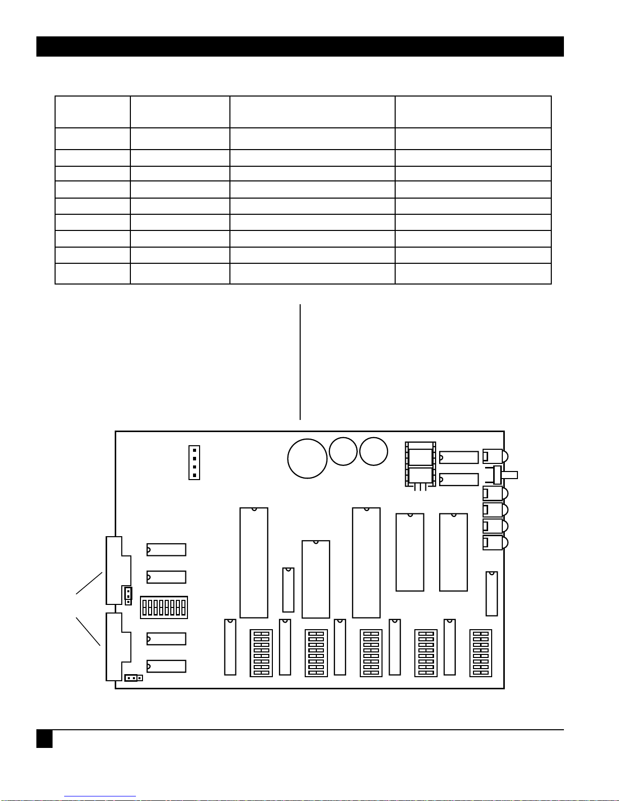
3.3 DIP Switch Settings
Positions 1-8 of each DIP switch can be turned ON
or OFF with a small-tipped instrument such as a
ball-point pen. A switch is OFF when it is pushed in
the direction of the arrow marked on the switch. If
it is pushed in the direction opposite the arrow, it is
ON.
If any switch positions are changed with the unit
turned off, the unit is automatically set to those
options when it is turned on. If the switches are
changed with the unit turned on, you must press
the Reset button to configure the unit with the new
settings. Figure 3-1 shows the location of the DIP
switches.
PIN NAME DESCRIPTION SOURCE
1 DCD Data Carrier Detect DCE
2 RD Receive Data DCE
3 TD Transmit Data DTE
4 DTR Data Terminal Ready DTE
5 SG Signal Ground DTE and DCE
6 DSR Data Set Ready DCE
7 RTS Request to Send DTE
8 CTS Clear to Send DCE
9 RI Ring Indicator DCE
Table 3-1. Pins Supported by the CAP
Figure 3-1. Switch Locations on the Circuit Board.
A
B
P1
A
DB9
CONNECTORS
W3
B
C
ON
S7
OFF
POWER
RESET
BUTTON
RXB
TXB
RXA
TXA
RAM
SIZE
C B A
W4
W2
A B C
S1 S2 S3 S4 S5
Page 10

CHAPTER 3: Installation
9
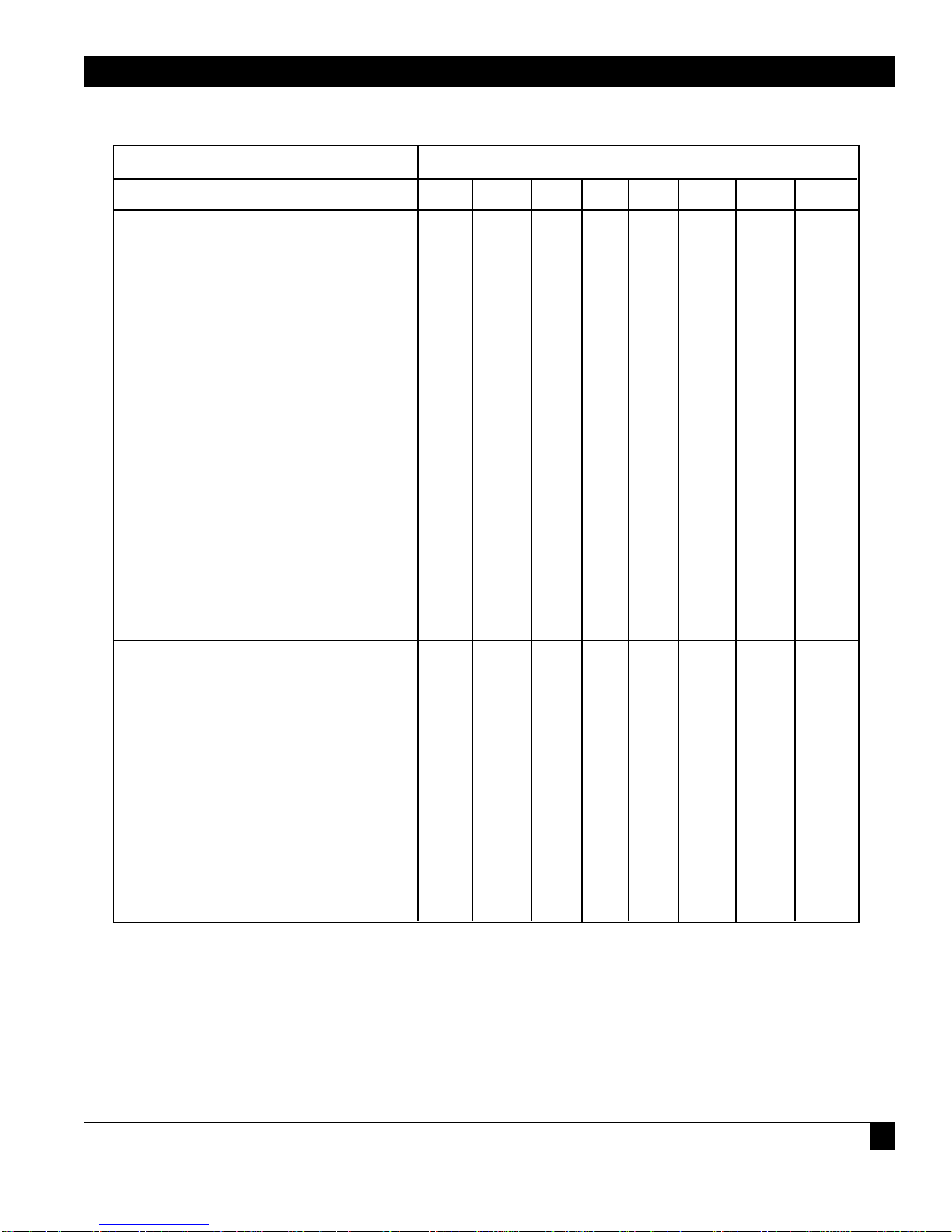
Table 3-2 defines the function of each of the unit's
switches. Tables 3-3 through 3-8 give switch settings
for particular applications.
Table 3-2. Switch Functions
Table 3-3. Switches S1 (Port A) and S2 (Port B)
SWITCH FUNCTION
S1 Port A word structure and buffer flow control
S2 Port B word structure and buffer flow control
S3 Port A baud rate and data code set
S4 Port B baud rate and data code set
S5 Ports A and B RS-232 lead options, equipment type,
transmission mode, and buffer allocation
S6 Reset Pushbutton
S7 RS-232 Interface Options
Table 3-3 shows settings for word structure and
buffer flow control.
OPTION SWITCH POSITION SETTING
1 234567 8
Word Structure
1 Stop Bit OFF OFF
1.5 Stop Bits ON OFF
1 Stop Bit OFF ON
2 Stop Bits ON ON
Odd Parity OFF
Even Parity ON
Parity Disable OFF
Parity Enable ON
8 Data Bits OFF OFF
7 Data Bits OFF ON
6 Data Bits ON OFF
5 Data Bits ON ON
Flow Control
Hardware OFF OFF
ENQ/ACK ON OFF
X-ON/X-OFF OFF ON
X-ON/X-OFF (X-ON on Reset) ON ON
Page 11

COMMUNICATIONS ADAPTER PLUS (CAP)
10
NOTE
For all hardware flow control, CTS and
DTR Switch 7 options must NOT be in
the forced active position.
For no flow control and normal
software flow controls (such as
X-ON/X-OFF and ENQ/ACK), the CTS
and DTR Switch 7 options should be in
the forced active position. See Tables 4-7
and 4-8 for Switch 7 Option settings.
3.4 Setting the Mark and Space Parity
In some cases, it is possible to use mark and space
parity. A mark parity bit represents a binary 1. A
space parity bit represents a binary 0.
To use either mark or space parity, Position 4 must
be OFF (to disable even or odd parity) and the
following conditions must be met.
• For Mark Parity — Mark parity can be used only
if your device is using a word structure
containing one stop bit. Set Positions 1 and 2
ON (2 stop bits). The first stop bit appears as a
mark parity bit.
• For Space Parity — Set the data bit switches for
one more data bit than the data code set
requires. For example, if your device is using the
7-bit ASCII code set, set Positions 5 and 6 for 8bit data (7 + 1 = 8). The extra data bit appears as
the space parity bit. The data bits required to
represent a character in each code set are as
follows:
ASCII 7
EBCDIC 8
BAUDOT 5
TICKER TAPE 6
TRANSCODE 6
NOTE
Space parity cannot be used for 8-bit
EBCDIC data because the CAP cannot
be configured for 9 data bits.
Table 3-4. Switch S3 (Port A) and S4 (Port B) Settings for Baud Rate and Data Code Set
OPTION SWITCH POSITION SETTING
1 234567 8
Baud Rate
38400 OFF OFF OFF OFF OFF
19200 ON OFF OFF OFF OFF
9600 OFF ON OFF OFF OFF
4800 ON ON OFF OFF OFF
4800 OFF OFF ON OFF OFF
2400 ON OFF ON OFF OFF
2400 OFF ON ON OFF OFF
1828.72 ON ON ON OFF OFF
1371.54 OFF OFF OFF ON OFF
1200 ON OFF OFF ON OFF
1037.92 OFF ON OFF ON OFF
600 ON ON OFF ON OFF
300 OFF OFF ON ON OFF
200 ON OFF ON ON OFF
Page 12
CHAPTER 3: Installation
11
Table 3-4 (continued). Switch S3 (Port A) and S4 (Port B) Settings for Baud Rate and Data Code Set
OPTION SWITCH POSITION SETTING
1 234567 8
Baud Rate
164.82 OFF ON ON ON OFF
150 ON ON ON ON OFF
1371.54 OFF OFF OFF OFF ON
1200 ON OFF OFF OFF ON
1037.92 OFF ON OFF OFF ON
600 ON ON OFF OFF ON
300 OFF OFF ON OFF ON
200 ON OFF ON OFF ON
164.82 OFF ON ON OFF ON
150 ON ON ON OFF ON
134.28 OFF OFF OFF ON ON
110.35 ON OFF OFF ON ON
100 OFF ON OFF ON ON
74.42 ON ON OFF ON ON
67.14 OFF OFF ON ON ON
55.82 ON OFF ON ON ON
50 OFF ON ON ON ON
45.5 ON ON ON ON ON
Data Code Set
ASCII OFF OFF OFF
EBCDIC ON OFF OFF
TRANSCODE OFF ON OFF
BAUDOT ON ON OFF
TICKER TAPE OFF OFF ON
ASCII ON OFF ON
ASCII OFF ON ON
OTHER (Use only if
both devices have the
same code set) ON ON ON
Page 13

COMMUNICATIONS ADAPTER PLUS (CAP)
12
NOTE
The selected baud rate can be within
4% of your desired rate and still allow
error-free communication.
NOTE
Make sure Switches S1 and S2 are set
for the correct number of data bits for
the particular Data Code set chosen
(Table 3-3 and the code set list in
Section 3.4).
OPTION SWITCH POSITION SETTING
1 234567 8
RS-232 Lead Options for Port A
Normal - RTS output rises when the
Port has data to transmit. Used for
half-duplex operation. OFF
Active - RTS outputs are always
active. ON
RS-232 Lead Options for Port B
Normal - RTS output rises when the
Port has data to transmit. Used for
half-duplex operation. OFF
Active - RTS outputs are always
active. ON
Equipment Type that Port A
Should Emulate
DCE — crossover cable OFF
DTE — straight-pinned cable ON
Transmission mode for Port A
Full duplex OFF
Half-duplex ON
Equipment Type that Port B
Should Emulate
DCE — crossover cable OFF
DTE — straight-pinned cable ON
Transmission Mode for Port B
Full duplex OFF
Half-duplex ON
Buffer Allocation
Port A Port B
1/2 1/2 OFF OFF
3/4 1/4 ON OFF
1/8 7/8 OFF ON
RESERVED ON ON
Table 3-5. Switch S5 Settings for the CAP
Page 14

CHAPTER 3: Installation
13
Table 3-6. Switch S7 Settings for the CAP
OPTION SWITCH POSITION SETTING
1 234567 8
RI Input Port A
RS-232 RI Connected (custom
programming only) ON
Forced Inactive (High) OFF
DTR Output Port A
Controlled by software (hardware
flow control) ON
Forced always active (High) OFF
DCD Input Port A
RS-232 DCD Connected input enables
Receive Data (Half-duplex)
Forced internally active (Receive ON
always enabled) OFF
CTS Input Port A
RS-232 CTS Connected input enables
Transmit Data (either hardware, or
both hardware and software flow
control)
Forced internally active (Receive ON
always enabled) OFF
RI Input Port B
RS-232 RI Connected (custom
programming only) ON
Forced active (High) OFF
DTR Output Port B
Controlled by software (hardware
flow control) ON
Forced active (High) OFF
DCD Input Port B
RS-232 DCD Connected input enables
Receive Data (Half-duplex)
Forced internally active (Receive ON
always enabled) OFF
CTS Input Port B
RS-232 CTS Connected input enables
Transmit Data)
Forced internally active ON
(Receive always enabled) OFF
Page 15

COMMUNICATIONS ADAPTER PLUS (CAP)
14
Table 3-7. DSR Jumper Settings for CAP
FUNCTION JUMPER POSITION
DSR Jumper for Port A — No Connection W2 — AB
DSR Jumper for Port A — DSR Output Always Active W2 — BC
DSR Jumper for Port B — No Connection W3 — AB
DSR Jumper for Port B — DSR Output Always Active W3 — BC
3.5 CAP to Device Connection
After the unit is programmed for your application,
you can physically install it.
Connect the unit to the two incompatible devices
with RS-232 cables. Make sure the port configured
for Device A is connected to Device A, and the port
configured for Device B is connected to Device B.
Apply AC Power.
Your unit is ready for operation.
Page 16

CHAPTER 4: Troubleshooting
15
If you have difficulty with your application, the
problem may be in either the unit's configuration
or the cabling between the devices. This chapter
advises you how to quickly find and correct the
problem.
4.1 Diagnostic LEDs
Five diagnostic LEDs are mounted on the front of
the unit. One LED is for POWER. Two LEDs are for
Port A, and two are for Port B. The two LEDs for
each port are Receive Data and Transmit Data. If
the unit does not appear to be communicating with
your devices, the following checklist may be useful.
1.Power — The Power LED should be on when
the unit is plugged into a wall outlet. The unit
will not operate without power.
2.RXA and RXB— These indicators flash when
the unit receives data to its A or B port. The unit
cannot pass information between two devices
unless it receives data to transmit. Never assume
your equipment is transmitting data to the unit.
Monitor this LED to verify that the unit is
actually receiving data. If this LED does not
flash when your device is transmitting to the
unit, check the following:
a) Verify whether your device is DTE or DCE.
b) Check that the crossover cable pinning is
correct.
If the LED flashes, another problem might be
that the CAP is ignoring the data your device is
sending. This happens if the CAP's receiver is
not enabled, or if the data doesn't have the
same baud rate/word structure that you have
configured for the CAP to use. Check the baud
rate/word structure and the DCD input DIP
switch options.
3.TXA and TXB — If the CAP receives data when
its receive enable is active, it puts the data in its
internal buffer. Then the CAP attempts to
transmit the data out the other port. However,
the CAP cannot transmit if it is flow-controlled
OFF. If the transmit LED does not light, check
the flow control and the CTS input DIP switch
options.
4.2 Cables and Configuration
If the LEDs for both ports are working properly, but
the two devices are not communicating with each
other, check the following:
1.Check for a good connection between Pins 2, 3,
and 7 of the cables that attach your equipment
to the CAP. These are the pins for TXD, RXD,
and Signal Ground.
2.Recheck all DIP switches and jumper positions
for both ports to verify that the CAP is
configured to match both devices it is
connecting. For example, if Port A is configured
to use one stop bit and your device is expecting
two, it may not receive the data correctly.
4 Troubleshooting
Page 17

COMMUNICATIONS ADAPTER PLUS (CAP)
16
This section contains tables that give the
hexadecimal number (followed by "H") for a
character in the ASCII, EBCDIC, Transcode,
Baudot, and Ticker Tape codes. The column
labeled "Character or Control" gives the character
that the hexadecimal number represents.
The characters are in the same order as the codes.
Looking at the first listing in Section 6.1, for
example, a 061H in ASCII is an "a," a 081H in
EBCDIC is an "a," a 001H in Transcode is an "A," a
003H in Baudot is an "A", and a 020H in Ticker
Tape is a special ticker-tape conversion character
called a special figure five (SF5). A lower-case "a" in
ASCII (061H) would be converted to a capital "A"
in Baudot (03H), because Baudot does not support
lower-case letters. An upper-case "A" in Baudot
would be converted to an upper-case "A" in ASCII
(see Section 5.2).
5.1 Lower-Case Letters
Only ASCII and EBCDIC support lower-case letters.
All lower-case letters are converted to upper-case
letters in the other codes, with the exception of
some ticker-tape codes.
5 Code Set Conversion Tables
ASCII EBCDIC Transcode Baudot Ticker Tape Character or Control
061H 081H 001H 003H 020H a a A A SF5
062H 082H 002H 019H 03BH b b B B 2ND B
063H 083H 003H 00EH 022H c c C C c
064H 084H 004H 009H 027H d d D D SF4
065H 085H 005H 001H 02FH e e E E SF3
066H 086H 006H 01DH 00DH f f F F F
067H 087H 007H 01AH 01AH g g G G G
068H 088H 008H 024H 025H h h H H S
069H 089H 009H 006H 006H i i I I I
06AH 091H 011H 00BH 00BH j j J J J
06BH 092H 012H 00FH 00FH k k K K K
06CH 093H 013H 022H 012H l l L L L
06DH 094H 014H 02CH 01CH m m M M M
06EH 095H 015H 00CH 00CH n n N N N
06FH 096H 016H 018H 018H o o O O O
070H 097H 017H 016H 004H p p P P PR
071H 098H 018H 017H 017H q q Q Q Q
072H 099H 019H 00AH 01FH r r R R RT
073H 0A2H 022H 005H 036H s s S S ST
074H 0A3H 023H 010H 032H t t T T SS
075H 0A4H 024H 007H 007H u u U U U
076H 0A5H 025H 01EH 01EH v v V V V
077H 0A6H 026H 013H 008H w w W W WI
078H 0A7H 027H 01DH 01DH x x X X X
079H 0A8H 028H 015H 02BH y y Y Y BEG ANN
07AH 0A9H 029H 011H 02AH z z Z Z END ANN
Page 18

CHAPTER 5: Code Set Conversion Tables
17
5.2 Upper-Case Letters
All upper-case letters can be converted, so only one letter is given in the "Character or Control" column.
ASCII EBCDIC Transcode Baudot Ticker Tape Character or Control
041H 0C1H 001H 003H 003H A
042H 0C2H 002H 019H 019H B
043H 0C3H 003H 00EH 00EH C
044H 0C4H 004H 009H 009H D
045H 0C5H 005H 001H 001H E
046H 0C6H 006H 00DH 00DH F
047H 0C7H 007H 01AH 01AH G
048H 0C8H 008H 014H 014H H
049H 0C9H 009H 006H 006H I
04AH 0D1H 011H 00BH 00BH J
04BH 0D2H 012H 00FH 00FH K
04CH 0D3H 013H 012H 012H L
04DH 0D4H 014H 01CH 01CH M
04EH 0D5H 015H 00CH 00CH N
04FH 0D6H 016H 018H 018H O
050H 0D7H 017H 016H 016H P
051H 0D8H 018H 017H 017H Q
052H 0D9H 019H 00AH 00AH R
053H 0E2H 022H 005H 005H S
054H 0E3H 023H 010H 010H T
055H 0E4H 024H 007H 007H U
056H 0E5H 025H 01EH 01EH V
057H 0E6H 026H 013H 013H W
058H 0E7H 027H 01DH 01DH X
059H 0E8H 028H 015H 015H Y
05AH 0E9H 029H 011H 011H Z
5.3 Numbers
All numbers can be converted. Therefore, only one number is given the "Character or Control" column.
ASCII EBCDIC Transcode Baudot Ticker Tape Character or Control
030H 0F0H 030H 016H 028H 0
031H 0F1H 031H 017H 023H 1
032H 0F2H 032H 013H 039H 2
033H 0F3H 033H 001H 02EH 3
034H 0F4H 034H 00AH 029H 4
035H 0F5H 035H 010H 021H 5
036H 0F6H 036H 015H 02DH 6
037H 0F7H 037H 007H 03AH 7
038H 0F8H 038H 006H 034H 8
039H 0F9H 039H 018H 026H 9
Page 19

COMMUNICATIONS ADAPTER PLUS (CAP)
18
5.4 Special Printable Characters
Any special printable character that cannot be
converted is changed to another character that is
a valid member for that code set. The common
character dash (-) is used, except for ticker-tape
code that can't be converted.
ASCII EBCDIC Transcode Baudot Ticker Tape Character or Control
020H 040H 01AH 004H 02CH SP (BAUDOT SP, SET 1B)
021H 05AH 020H 003H 038H ! ! - - 022H 07FH 020H 011H 038H " " - " 023H 07BH 03BH 014H 038H # # # # 024H 05BH 01BH 00DH 03CH $
025H 06CH 02CH 003H 038H % % % - 026H 050H 010H 01AH 01BH &
027H 07DH 020H 005H 038H ' ' - ' 028H 04DH 020H 00FH 038 ( ( - ( 029H 05DH 020H 012H 038H ) ) - ) 02AH 05CH 01CH 003H 038H * * * - 02BH 04EH 020H 009H 038H + + - + 02CH 06BH 02BH 00CH 038H ' ' ' ' -
02EH 04BH 00BH 01CH 024H . . . . FIGURE
DOT
02FH 061H 021H 01DH 002H / / / / LETTER
DOT
03AH 07AH 020H 00EH 038H : : - : 03BH 05EH 020H 01EH 038H ; ; - ; 03CH 04CH 00CH 003H 038H < < < - .03DH 07EH 020H 003H 038H = = - - 03EH 06EH 020H 003H 03EH > > - - 3/8
03FH 06FH 020H 019H 038H ? ? - ? 040H 07CH 03CH 003H 038H @ @ @ - 05BH 0ADH 020H 003H 037H [ [ - - 1/4
05CH 0E0H 020H 003H 038H \ \ - - 05DH 0BDH 020H 003H 035H ] ] - - 3/4
05EH 060H 020H 003H 038H ^ --05FH 06DH 020H 003H 038H _ _ - - 060H 079H 020H 00CH 038H ' ' - ' 07BH 0C0H 020H 003H 033H { { - - 1/2
07CH 06AH 020H 003H 030H | | - - 1/8
07DH 0D0H 020H 003H 031H } } - - 7/8
07EH 0A1H 020H 003H 03DH ~ ~ - - 5/8
02DH 060H 020H 003H 038H -
Page 20

CHAPTER 5: Code Set Conversion Tables
19
5.5 Control Codes
Any control code that cannot be converted is
discarded and shown as an OFFH.
ASCII EBCDIC Transcode Baudot Ticker Tape Character or Control
006H 02EH 0FFH 0FFH 0FFH ACK
007H 02FH 00DH 00BH 0FFH BEL
008H 016H 0FFH 0FFH 0FFH BS
0FFH 024H 0FFH 0FFH 0FFH BYP
018H 018H 0FFH 0FFH 0FFH CAN
0FFH 01AH 0FFH 0FFH 0FFH CC
00DH 00DH 0FFH 008H 0FFH CR
011H 011H 0FFH 0FFH 0FFH DC1
012H 012H 0FFH 0FFH 0FFH DC2
013H 013H 0FFH 0FFH 0FFH DC3
014H 03CH 0FFH 0FFH 0FFH DC4
07FH 007H 03FH 0FFH 03FH DEL
& Rubout in Ticker Tape
010H 010H 01FH 0FFH 0FFH DLE
0FFH 020H 0FFH 0FFH 0FFH DS
019H 019H 03EH 0FFH 0FFH EM
005H 02DH 02DH 0FFH 0FFH ENQ
0FFH 026H 0FFH 0FFH 0FFH EQB
004H 037H 01EH 0FFH 0FFH EOT
01BH 027H 02AH 0FFH 0FFH ESC
017H 026H 00FH 0FFH 0FFH ETB
003H 003H 02EH 0FFH 0FFH ETX
00CH 00CH 0FFH 0FFH 0FFH FF
01CH 022H 0FFH 0FFH 0FFH FS
01DH 0FFH 0FFH 0FFH 0FFH GS
009H 005H 02FH 0FFH 0FFH HT
0FFH 01CH 0FFH 0FFH 0FFH IFS
0FFH 01DH 0FFH 0FFH 0FFH IGS
0FFH 017H 0FFH 0FFH 0FFH IL
0FFH 01EH 0FFH 0FFH 0FFH IRS
0FFH 01FH 0FFH 0FFH 0FFH IUS
0FFH 006H 0FFH 0FFH 0FFH LC
00AH 025H 0FFH 002H 0FFH LF
(BAUDOT LF BOTH SETS)
015H 03DH 03DH 0FFH 0FFH NAK
0FFH 015H 0FFH 0FFH 0FFH NL
000H 000H 0FFH 000H 000H NUL & SPARE IN
TICKER TAPE
Page 21

COMMUNICATIONS ADAPTER PLUS (CAP)
20
ASCII EBCDIC Transcode Baudot Ticker Tape Character or Control
0FFH 004H 0FFH 0FFH 0FFH PF
0FFH 034H 0FFH 0FFH 0FFH PN
0FFH 027H 0FFH 0FFH 0FFH PRE
0FFH 014H 0FFH 0FFH 0FFH RES
0FFH 009H 0FFH 0FFH 0FFH RLF
01EH 035H 0FFH 0FFH 0FFH RS
00FH 00FH 0FFH 0FFH 0FFH SI
0FFH 02AH 0FFH 0FFH 0FFH SM
0FFH 00AH 0FFH 0FFH 0FFH SMM
00EH 00EH 0FFH 0FFH 0FFH SO
001H 001H 000H 0FFH 0FFH SOH
0FFH 021H 0FFH 0FFH 0FFH SOS
002H 002H 00AH 0FFH 0FFH STX
01AH 03FH 00EH 0FFH 0FFH SUB
016H 032H 03AH 0FFH 0FFH SYN
0FFH 036H 0FFH 0FFH 0FFH UC
01FH 0FFH 01DH 0FFH 0FFH US
00BH 00BH 0FFH 0FFH 0FFH VT
5.6 Ticker Tape
The special codes in Ticker Tape (shown on the
next page) cannot be converted to any of the other
code sets. These codes are changed to other
printable codes that Ticker Tape does not support.
This allows the user to interpret Ticker Tape data
by checking for these codes.
ASCII and EBCDIC are the only code sets in which
all of the changed codes are valid. Transcode and
Baudot do not have many codes that Ticker Tape
does not support. To interpret the special Ticker
Tape codes available, the Baudot and Transcode
code sets would need more of these available codes.
For example, if a Ticker Tape "WI" is sent to a
Transcode device, it is interpreted as a "W." If a
Transcode device sends a "W" to a Ticker Tape
device it is interpreted as a "W," not as a "WI."
Page 22

CHAPTER 5: Code Set Conversion Tables
21
Changed
Ticker Char ASCII Baudot
HEX Tape EBCDIC Transcode Description
00 NUL * Spare code
02 . / / Letters dot
04 P P P "P" with "R" below
R
08 W w W "W" with "I" below
I
1F R r R "R" with "T" below
T
20 . a A Special Figure 5
22 c c C Lower Case "C"
24 . . . Figures Dot
25 s s S Lower Case "s"
27 1 d D "1" with "4" below (1/4 Option 2)
4
2A . z Z End Announcement
2B . y Y Begin Announcement
2F . e E Special Figure 3
30 1 | - "1" with "8" below (1/8)
8
31 7 } - "7" with "8" below (7/8)
8
32 S t T "S" with "S" below
S
33 1 { - "1" with "2" below (1/2)
2
35 3 ] - "3" with "4" below (3/4)
4
36 S s S "S" with "T" below
T
37 1 [ - "1" with "4" below (1/4 Option 1)
4
3B B b B Another code for "B"
3D 5 ~ - "5" with "8" below (5/8)
8
3E 3 > - "3" with "8" below (3/8)
8
3F . DEL ** Rubout
*No conversion
**Del in Transcode, no conversion in Baudot
Page 23

CAP AND USER PROGRAMMABLE CAP
22
This appendix shows the special pinning required
for the CAP to operate in particular applications. If
your application matches the caption of one of the
pinning diagrams below, make sure the cable you
are using matches the pinning shown.
The diagrams are set up so that the left side of the
illustration shows pinning on one end of the cable,
while the right side shows pinning on the other
side. Pins that are directly across from each other
are directly connected.
Appendix: Optional Cables
Figure A-1. CAP-to-DTE Cable
(DB9 to DB25 Male Cable).
(EHN023)
Figure A-2. CAP-to-Modem Cable
(DB9 to DB25 Male Cable).
(EHN024)
DCE Device
CAP DTE Device
DB9M DB25M
DCD
RXD
TXD
DTR
GND
1
2
3
4
5
4
2
3
5
7
RTS
TXD
RXD
CTS
GND
CAP
DB9M
DCD
RXD
TXD
DTR
GND
1
2
3
4
5
DTE Device
DB25M
8
DCD
3
RXD
2
TXD
20
DTR
7
GND
DSR
6
6
DSR
21 SQD
RTS
CTS
RI
7
8
9
8
20
23
DCD
DTR
DRS
6
4
5
22
DSR
RTS
CTS
RI
DSR
RTS
CTS
RI
6
7
8
9
Page 24

APPENDIX: Optional Cables
23
Figure A-3. CAP-to-AT Cable
(DB9 to DB9 Cable for AT).
(EHN025)
Figure A-4. CAP-to-DCE Cable
(DB9 to DB9 Cable).
(ECN12D)
Figure A-5. CAP-to-PC Cable
(DB9 to DB25 Female Cable).
(EHN026)
1
2
3
4
5
DB9*
7
8
9
*Must
specify
gender
type when
ordering.
CAP
DB9M
DCD
RXD
TXD
DTR
GND
DSR
RTS
CTS
RI
AT SERIAL PORT
1
2
3
4
5
6
7
8
9
DB9F
RTS
7
TXD
3
2
RXD
8
CTS
5
GND
6
DSR
1
DCD
4
DTR
9
RI
CAP
DB9M
DCD
1
RXD
2
TXD
3
DTR
4
GND
5
DSR
6
RTS
7
CTS
8
RI
9
DCE Device
DB25M
8
DCD
RXD
3
TXD
2
DTR
20
GND
7
DSR
6
RTS
4
CTS
5
RI
22
CAP PC SERIAL PORT
DB9M DB25F
DCD
RXD
TXD
DTR
GND
DSR
1
2
3
4
5
6
4
2
3
5
7
6
RTS
TXD
RXD
CTS
GND
DSR
21 SQD
RTS
CTS
RI
7
8
9
8
20
23
DCD
DTR
DRS
Page 25

CAP AND USER PROGRAMMABLE CAP
24
CAP DB9 female
Signal Pin Direction
DCD 1 Input
RXD 2 Input
TXD 3 Output
DTR 4 Output
GND 5
DSR 6 Output or N/A
RTS 7 Output
CTS 8 Input
RI 9 Input
Figure A-6. RS-232 Port(s) Pinouts and Signal Flow for Both CAP Ports.
Page 26

P1
S7
W3
W2
W4
S1 S2 S3 S4 S5
ON
OFF
A
B
C
A B C
C B A
RAM
SIZE
POWER
RESET
BUTTON
RXB
TXB
RXA
TXA
DB9
CONNECTORS
S6
Switches S1 (Port A) and S2 (Port B)
POSITION 1 2 WORD STRUCTURE
OFF OFF 1 stop bit
ON OFF 1 1/2 stop bits
OFF ON 1 stop bit
ON ON 2 stop bit
POSITION 3
OFF Odd parity (See Section 3.4 for
Mark and Space Parity)
ON Even parity
POSITION 4
OFF Parity disable (voids Position 3)
ON Parity enable
POSITION 5 6
OFF OFF 8 data bits
OFF ON 7 data bits
ON OFF 6 data bits
ON ON 5 data bits
POSITION 7 8 BUFFER FLOW CONTROL
OFF OFF Hardware flow control using
CTS/DTR, or no flow control
ON OFF ENQ/ACK buffer flow control
OFF ON XON/XOFF buffer flow control
ON* ON XON/XOFF buffer flow control
*(CAP transmits an X-ON code
out the port on Reset, as, after
a power failure.)
NOTE: For all hardware flow control, CTS and DTR Switch 7
options must NOT be in the “forced active” position.
For no flow control and normal software flow controls
(X-ON/X-OFF and ENQ/ACK) the CTS and DTR
Switch 7 options should be in the “forced active” position.
S3 and S4 Switch Settings for Baud Rate and Data Code Set
POSITION Baud Rate with Baud Rate with
1 2 3 4 Position 5 OFF Position 5 ON
OFF OFF OFF OFF 38,400 1,371.54
ON OFF OFF OFF 19,200 1,200
OFF ON OFF OFF 9,600 1,037.92
ON ON OFF OFF 4,800 600
OFF OFF ON OFF 4,800 300
ON OFF ON OFF 2,400 200
OFF ON ON OFF 2,400 164.82
ON ON ON OFF 1,828.72 150
OFF OFF OFF ON 1,371.54 134.28
ON OFF OFF ON 1,200 110.35
OFF ON OFF ON 1,037.92 100
ON ON OFF ON 600 74.42
OFF OFF ON ON 300 67.14
ON OFF ON ON 200 55.82
OFF ON ON ON 164.82 50
ON ON ON ON 150 45.5
NOTE: If your desired baud rate is within ±4% of one listed above, in most
cases you should set the CAP to the listed rate.
Make certain Switches S1 and S2 are set for the correct number of
data bits for the particular Data Code Set chosen (see Table 4-3 and
the code set list in Section 4.4).
6 7 8 DATA CODE SET
OFF OFF OFF ASCII
ON OFF OFF EBCDIC
OFF ON OFF TRANSCODE
ON ON OFF BAUDOT
OFF OFF ON TICKER TAPE
ON OFF ON ASCII
OFF ON ON ASCII
ON ON ON OTHER may be
chosen only if both
devices use the same
code set.
Switch S5 Settings
RS-232 lead options, equipment type, transmission mode,
and buffer allocation
POSITION 1 RS-232 Lead options for PORT A
OFF Normal - RTS output rises only
when the port has data to transmit.
Normal must be used for halfduplex operation.
ON Active - RTS outputs are always
active.
POSITION 2 RS-232 Lead options for PORT B
OFF Normal - RTS output rises only
when the port has data to transmit.
Normal must be used for halfduplex operation.
ON Active - RTS outputs are always
active.
POSITION 3 Equipment type CAP should
emulate (Port A)
OFF* DCE - When using crossover cable
ON DTE - When using straight-pinned
cable
POSITION 4 Transmission mode for PORT A
OFF Full duplex/Simplex
ON Half-duplex (hardware flow
control configuration must be
used with half duplex.)
POSITION 5 Equipment type CAP should
emulate (Port B)
OFF* DCE - When using crossover cable
ON DTE - When using straight-pinned
cable
POSITION 6 Transmission mode for PORT B
OFF Full duplex/Simplex
ON Half-duplex
POSITION 7 8 Buffer allocation**
Port A Port B
OFF OFF 1/2 1/2
ON OFF 3/4 1/4
OFF ON 1/8 7/8
ON ON RESERVED
*A CAP crossover cable must be attached to the CAP for it
to emulate DCE in addition to selecting the DIP switch
option to emulate DCE. See the Appendix for more on cable
pinning.
* *Buffer allocation is for data being received by that port
(input data).
Switch S7 Settings
POSITION 1 RI Input Port A
ON RS-232 RI connected (custom programming only)
OFF Forced inactive (High)
POSITION 2 DTR Output Port A
ON Controlled by software (hardware flow control)
OFF Forced always active (High)
POSITION 3 DCD Input Port A
ON RS-232 DCD Connected (enables Receive data)
OFF Forced active (High)
POSITION 4 CTS Input Port A
ON RS-232 CTS connected (enables Transmit data)
OFF Forced active (High)
POSITION 5 RI Input Port B
ON RS-232 RI connected (custom programming only)
OFF Forced active (High)
POSITION 6 DTR Output Port B
ON Controlled by software (hardware flow control)
OFF Forced active (High)
POSITION 7 DCD input Port B
ON RS-232 DCD connected (enables Receive data)
OFF Forced active (High)
POSITION 8 CTS Input Port B
ON RS-232 CTS connected (enables Transmit data)
OFF Forced active (High)
DSR Jumper Settings
W2 DSR Jumper for Port A
A-B No connection
B-C DSR always active
W3 DSR Jumper for Port B
A-B No connection
B-C DSR always active
CAP Circuit Board
The CAP Quick Setup
NOTE: The direction of the arrow on the DIP switch is OFF.
B
A
Page 27

© Copyright 1995. Black Box Corporation. All rights reserved.
1000 Park Drive • Lawrence, PA 15055-1018 • 724-746-5500 • Fax 724-746-0746
 Loading...