

Page 1
ACU5520A
®
®
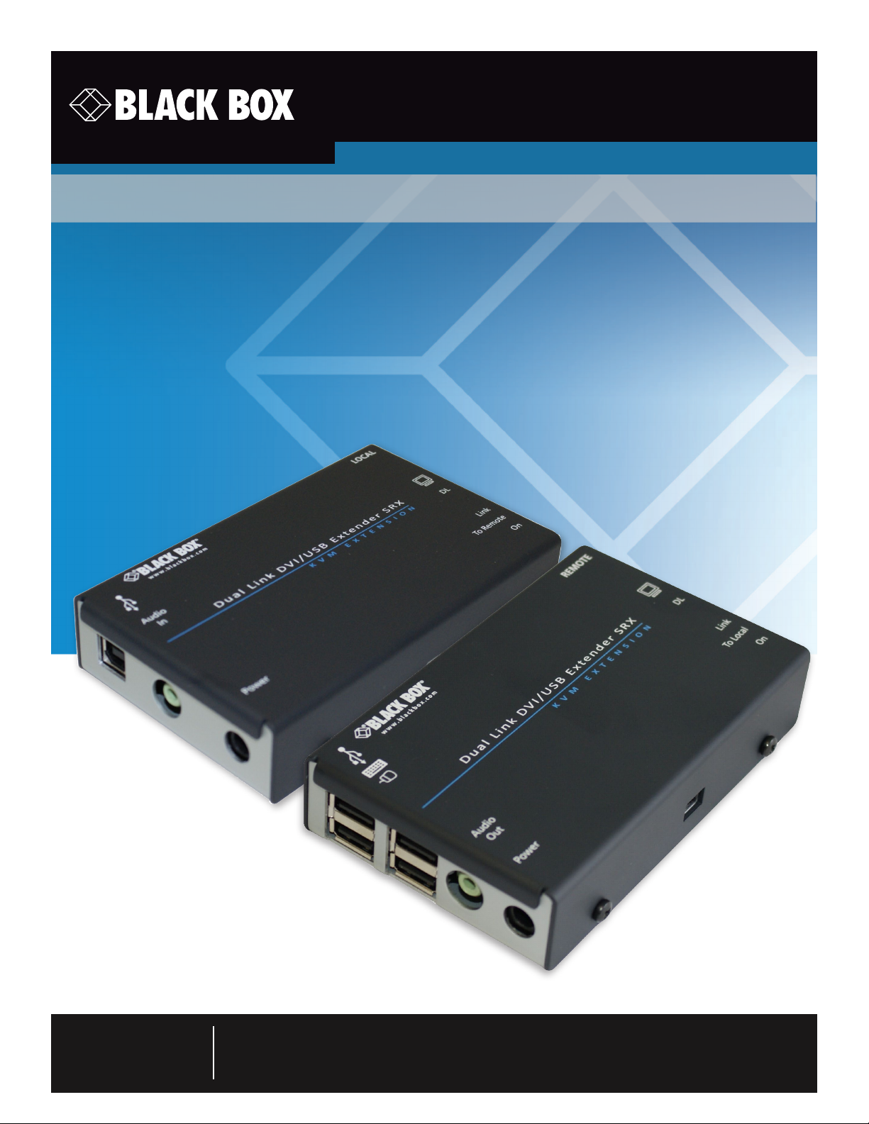
Dual Link DVI/USB Extender SRX
™
Extend DVI-D dual link video plus four USB devices
up to 165 feet (50m) from your computer.
Uses just one length of Category 6a or 7 twisted-pair cable.
Customer
Support
Information
Order toll-free in the U.S.: Call 877-877-BBOX (outside U.S. call 724-746-5500)
FREE technical support 24 hours a day, 7 days a week: Call 724-746-5500 or fax 724-746-0746
www.blackbox.com • info @blackbox.com
Page 2

Dual Link DVI/USB Extender SRX
Trademarks Used in this Manual
Black Box and the Double Diamond logo are registered trademarks, and ServSwitch is a trademark, of BB Technologies, Inc.
Mac is a registered trademark of Apple Computer, Inc.
Linux is registered trademark of Linus Torvalds.
Windows is a registered trademark of Microsoft Corporation.
NetWare is a registered trademark of Novell, Inc.
Sun is a trademark of Sun Microsystems, Inc.
Unix is a registered trademark of UNIX System Laboratories, Inc.
BSD is a registered trademark of UUNet Technologies, Inc.
Any other trademarks mentioned in this manual are acknowledged to be the property of the trademark owners.
Page 2
We‘re here to help! If you have any questions about your application
or our products, contact Black Box Tech Support at 724-746-5500
or go to blackbox.com and click on “Talk to Black Box.”
You’ll be live with one of our technical experts in less than 60 seconds.
724-746-5500 | blackbox.com
Page 3

FCC and IC RFI Statements
Federal Communications Commission and Industry Canada Radio Frequency Interference
Statements
This equipment generates, uses, and can radiate radio-frequency energy, and if not installed and used properly, that is, in strict
accordance with the manufacturer’s instructions, may cause inter ference to radio communication. It has been tested and found to
comply with the limits for a Class A computing device in accordance with the specifications in Subpart B of Part 15 of FCC rules,
which are designed to provide reasonable protection against such interference when the equipment is operated in a commercial
environment. Operation of this equipment in a residential area is likely to cause interference, in which case the user at his own
expense will be required to take whatever measures may be necessary to correct the interference.
Changes or modifications not expressly approved by the party responsible for compliance could void the user’s authority to
operate the equipment.
This digital apparatus does not exceed the Class A limits for radio noise emis sion from digital apparatus set out in the Radio
Interference Regulation of Industry Canada.
Le présent appareil numérique n’émet pas de bruits radioélectriques dépassant les limites applicables aux appareils numériques de
la classe A prescrites dans le Règlement sur le brouillage radioélectrique publié par Industrie Canada.
724-746-5500 | blackbox.com
Page 3
Page 4

Dual Link DVI/USB Extender SRX
Instrucciones de Seguridad
(Normas Oficiales Mexicanas Electrical Safety Statement)
1. Todas las instrucciones de seguridad y operación deberán ser leídas antes de que el aparato eléctrico sea operado.
2. Las instrucciones de seguridad y operación deberán ser guardadas para referencia futura.
3. Todas las advertencias en el aparato eléctrico y en sus instrucciones de operación deben ser respetadas.
4. Todas las instrucciones de operación y uso deben ser seguidas.
5. El aparato eléctrico no deberá ser usado cerca del agua—por ejemplo, cerca de la tina de baño, lavabo, sótano mojado o cerca
de una alberca, etc.
6. El aparato eléctrico debe ser usado únicamente con carritos o pedestales que sean recomendados por el fabricante.
7. El aparato eléctrico debe ser montado a la pared o al techo sólo como sea recomendado por el fabricante.
8. Servicio—El usuario no debe intentar dar servicio al equipo eléctrico más allá a lo descrito en las instrucciones de operación.
Todo otro servicio deberá ser referido a personal de servicio calificado.
9. El aparato eléctrico debe ser situado de tal manera que su posición no interfiera su uso. La colocación del aparato eléctrico
sobre una cama, sofá, alfombra o superficie similar puede bloquea la ventilación, no se debe colocar en libreros o gabinetes
que impidan el flujo de aire por los orificios de ventilación.
10. El equipo eléctrico deber ser situado fuera del alcance de fuentes de calor como radiadores, registros de calor, estufas u otros
aparatos (incluyendo amplificadores) que producen calor.
11. El aparato eléctrico deberá ser connectado a una fuente de poder sólo del tipo descrito en el instructivo de operación, o como
se indique en el aparato.
12. Precaución debe ser tomada de tal manera que la tierra fisica y la polarización del equipo no sea eliminada.
13. Los cables de la fuente de poder deben ser guiados de tal manera que no sean pisados ni pellizcados por objetos colocados
sobre o contra ellos, poniendo particular atención a los contactos y receptáculos donde salen del aparato.
14. El equipo eléctrico debe ser limpiado únicamente de acuerdo a las recomendaciones del fabricante.
15. En caso de existir, una antena externa deberá ser localizada lejos de las lineas de energia.
16. El cable de corriente deberá ser desconectado del cuando el equipo no sea usado por un largo periodo de tiempo.
17. Cuidado debe ser tomado de tal manera que objectos liquidos no sean derramados sobre la cubierta u orificios de ventilación.
18. Servicio por personal calificado deberá ser provisto cuando:
A: El cable de poder o el contacto ha sido dañado; u
B: Objectos han caído o líquido ha sido derramado dentro del aparato; o
C: El aparato ha sido expuesto a la lluvia; o
D: El aparato parece no operar normalmente o muestra un cambio en su desempeño; o
E: El aparato ha sido tirado o su cubierta ha sido dañada.
Page 4
724-746-5500 | blackbox.com
Page 5

Table of Contents
Contents
1. Specifications .............................................................................................................................................................................. 6
2. Welcome .................................................................................................................................................................................... 7
3. Installation .................................................................................................................................................................................. 8
3.1 Mounting the modules – desk or rack............................................................................................................................... 8
3.1.1 D e s k m ount .......................................................................................................................................................... 8
3.1.2 Rack mount .......................................................................................................................................................... 9
3.2 Connections ................................................................................................................................................................... 10
3.2.1 Connections at the local module ........................................................................................................................ 10
3.2.2 Connections at the remote module ................................................................................................................... 14
4. Operation ..................................................................................................................................................................................17
4.1 General use ......................................................................................................................................................................17
4.2 Video display (EDID) information .....................................................................................................................................17
4.3 HDMI 1.3a operation .......................................................................................................................................................17
4.4 Power and activity indicators .......................................................................................................................................... 18
Appendix A. Troubleshooting ....................................................................................................................................................... 19
Appendix B. Safety Information .................................................................................................................................................... 20
724-746-5500 | blackbox.com
Page 5
Page 6

Dual Link DVI/USB Extender SRX
1. Specifications
Approvals: CE, FCC
Hardware Compatibility: All computers with DVI-D digital video and USB interfaces
Software Compatibility: Operates with all known software and operating systems including
Windows®, Linux®, Unix®, BSD, all Sun® OS, all Mac® OS, NetWare®, etc.
Connectors:
(local transmitter) Video: DVI-D female
USB: USB Type B female
Audio: 1 x 3.5mm jack socket
Other: RJ-45 CATx link socket
Power jack
Connectors: Video: DVI-D female
(remote receiver) USB: (4) USB Type A female
Audio: 1 x 3.5mm jack socket
Other: RJ-45 CATx link socket
Power jack
Operating Temperature: 32 to 104°F (0 to 40°C)
Power adapter(s): Input: 100–240 VAC, 50/60 Hz
Output: DC jack (5VDC output)
Dimensions
(w): 120mm (4.66”)
(h): 26mm (1.02”)
(d): 75mm (2.94”)
Weight: 0.32kg (0.7lbs)
Power requirements: 400mA @ 5VDC
Page 6
724-746-5500 | blackbox.com
Page 7
Chapter 2: Overview
2. Welcome
Thank you for choosing the Black Box Dual Link DVI/USB Extender SRX units. These compact modules provide the quickest way
to extend high quality dual link DVI digital video plus USB keyboard, mouse and stereo audio with an additional two USB peripherals up to 165 feet (50 meters) away from your computer.
Thanks to our long involvement and investment in extender technology we have succeeded in overcoming the numerous problems associated with extending digital video signals. Using our proprietary transmission techniques these modules can extend all
dual link video resolutions up to 2560 x 1600. In effect, these modules can reliably transfer video rates up to 330 Mpixels per second. This is in addition to multiple USB channels plus stereo audio - all via the same single length of CAT6a or CAT7 shielded
twisted pair cabling.
The Dual Link DVI/USB Extender SRX modules have been designed to be quick to install and totally transparent in operation.
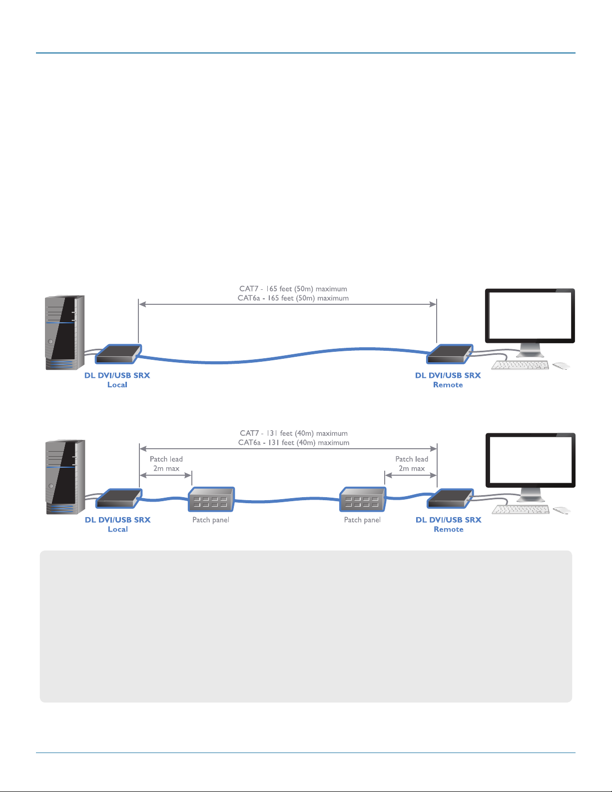
Dual Link DVI/USB Extender SRX link with direct cable connection
Dual Link DVI/USB Extender SRX link with cable and patch panel connection
Cable type and distance rules
• Cablescreeningisparamount.Thebestcable
screening specifications for digital KVM extension are:
S/FTP, S/STP or PiMF.
• Extensiondistancesupto50maresupportedwith
single uninterrupted runs of recommended cable
(Black Box CAT7a patch cable) at full resolution.
• Extensionsof50mmaybeachievedwithsingle
uninterrupted runs of shielded CAT6a bulk/trunk (not
patch) cable at full resolution.
• BlackBoxdoesnotrecommendCAT5ecablesforuse
with this product.
• Overallcablerunsmustbereducedby5mforeach
additional cable coupling.
• Runspecicationsmaybeincreasedby10mwhen
using resolutions of 1280 x 1024 or lower.
• Allpatchcablesshouldbeasshortaspossibleand
should be no longer than 2m.
• ItisrecommendedthatBlackBoxCAT7apatchcables
are used for maximum performance.
724-746-5500 | blackbox.com
Page 7
Page 8
Dual Link DVI/USB Extender SRX
3. Installation
3.1 Mounting the modules – desk or rack
The Dual Link DVI/USB Extender SRX modules can be situated on a desk or alternatively, for larger installations, mounted within
an optional rack mount chassis.
3.1.1 Desk mount
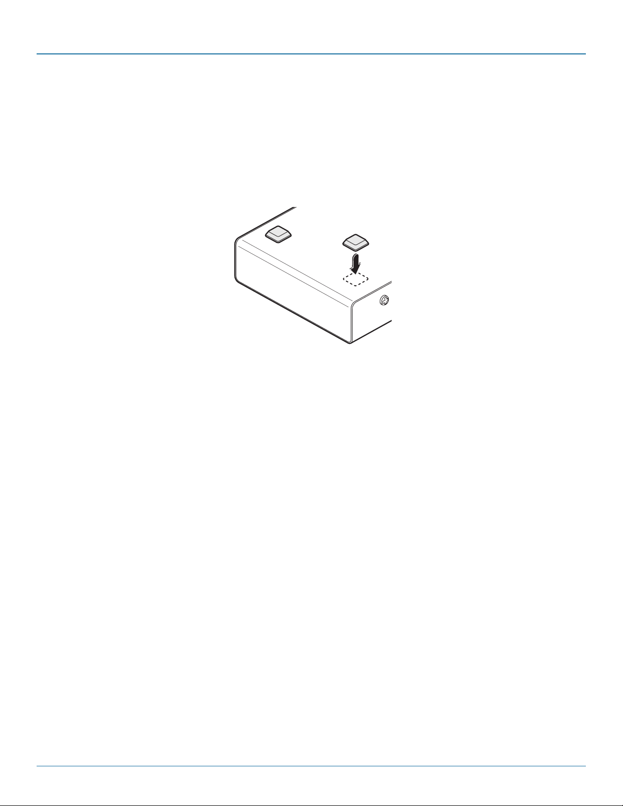
Apply the supplied self-adhesive rubber feet to the underside of the module as shown in Figure 3-1:
Figure 3-1. Applying the supplied self-adhesive rubber feet to the underside of the module
Page 8
724-746-5500 | blackbox.com
Page 9
Chapter 3: Installation
3.1.2 Rack mount
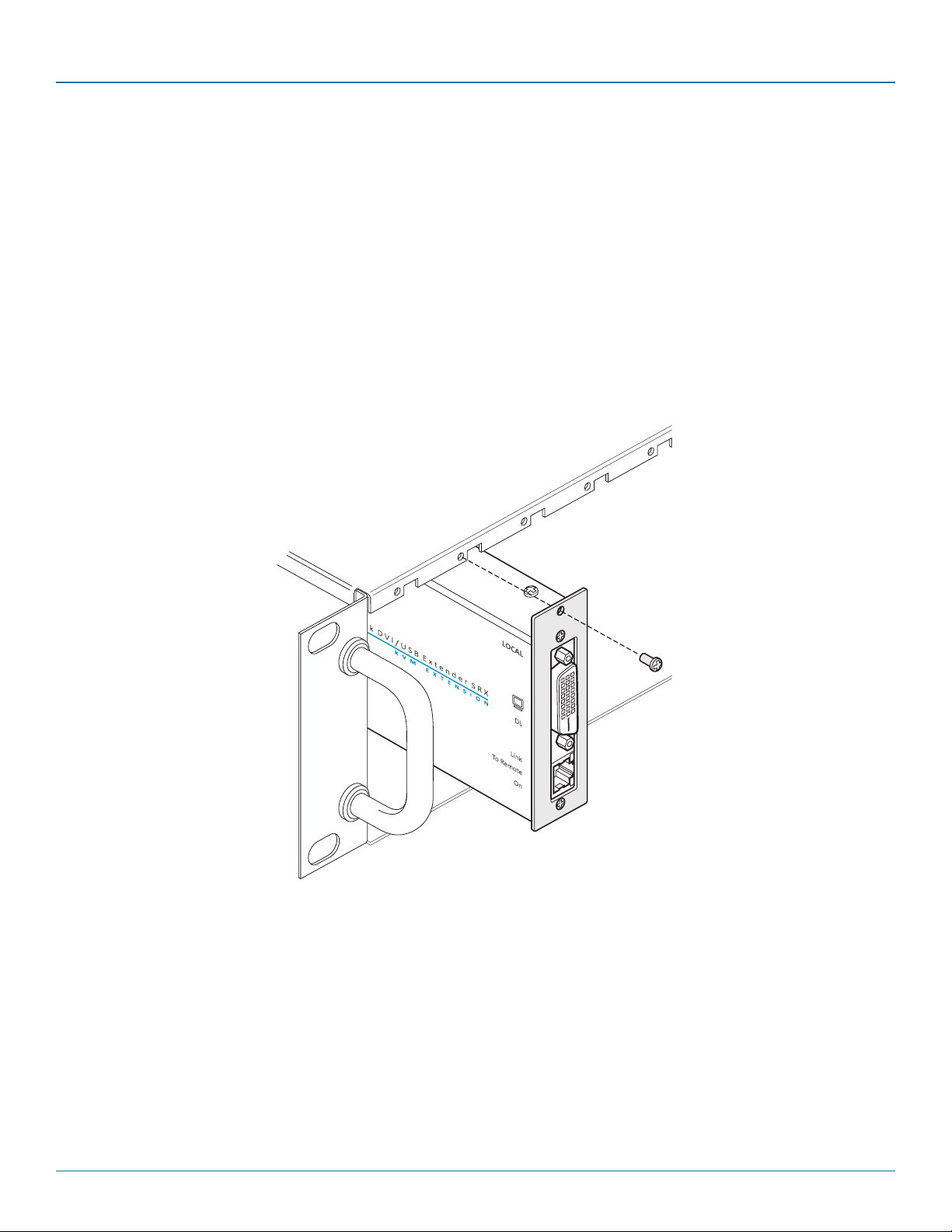
Note: The module switches are not accessible once it is inserted into the rack, therefore, check all settings before insertion.
1 Place the rack securing plate (available as a separate kit) onto the front of the module and secure it with the two countersunk
screws.
2 Orient the Dual Link DVI/USB Extender SRX module on its side so that its labeled face is the correct way up.
3 Slide the module into the required rack position. The rectangular cut-out in the front upper lip of the rack allows the two
screws on the module’s upper edge to slide through.
4 The rack mount chassis has a series of holes in its floor that are spaced to accommodate the two screws on the module’s lower
edge. Ensure that the screws correctly locate into the two holes of the chosen slot. The rack securing plate on the module
should now be flush with the front of the rack mount chassis.
5 Use the third (pan-head) screw, in the top hole of the rack securing plate to fasten the module to the rack as shown in Figure
3-2:
Figure 3-2. Fixing the module into the rack
724-746-5500 | blackbox.com
Page 9
Page 10
Dual Link DVI/USB Extender SRX
3.2 Connections
Installation of the Dual Link DVI/USB Extender SRX modules is straightforward and requires minimal configuration in most cases.
• Connectionsatthelocalmodule
• Connectionsattheremotemodule
Note: After all connections are made, power up the monitor connected to the remote module, then power up the remote module and finally switch on the computer connected to the local module.
3.2.1 Connections at the local module
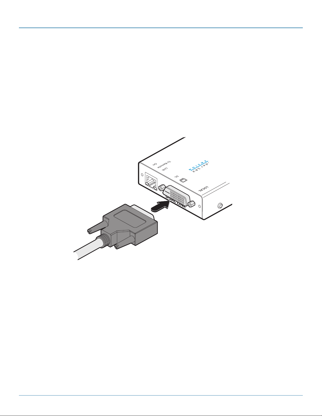
3.2.1.1 Video connection
1 Use the supplied DVI/ D link cable to connect the DVI input socket of the local module to the digital video output socket of the
computer as shown in Figure 3-3:
Page 10
Figure 3-3. Attaching the DVI/D video link cable
724-746-5500 | blackbox.com
Page 11
Chapter 3: Installation
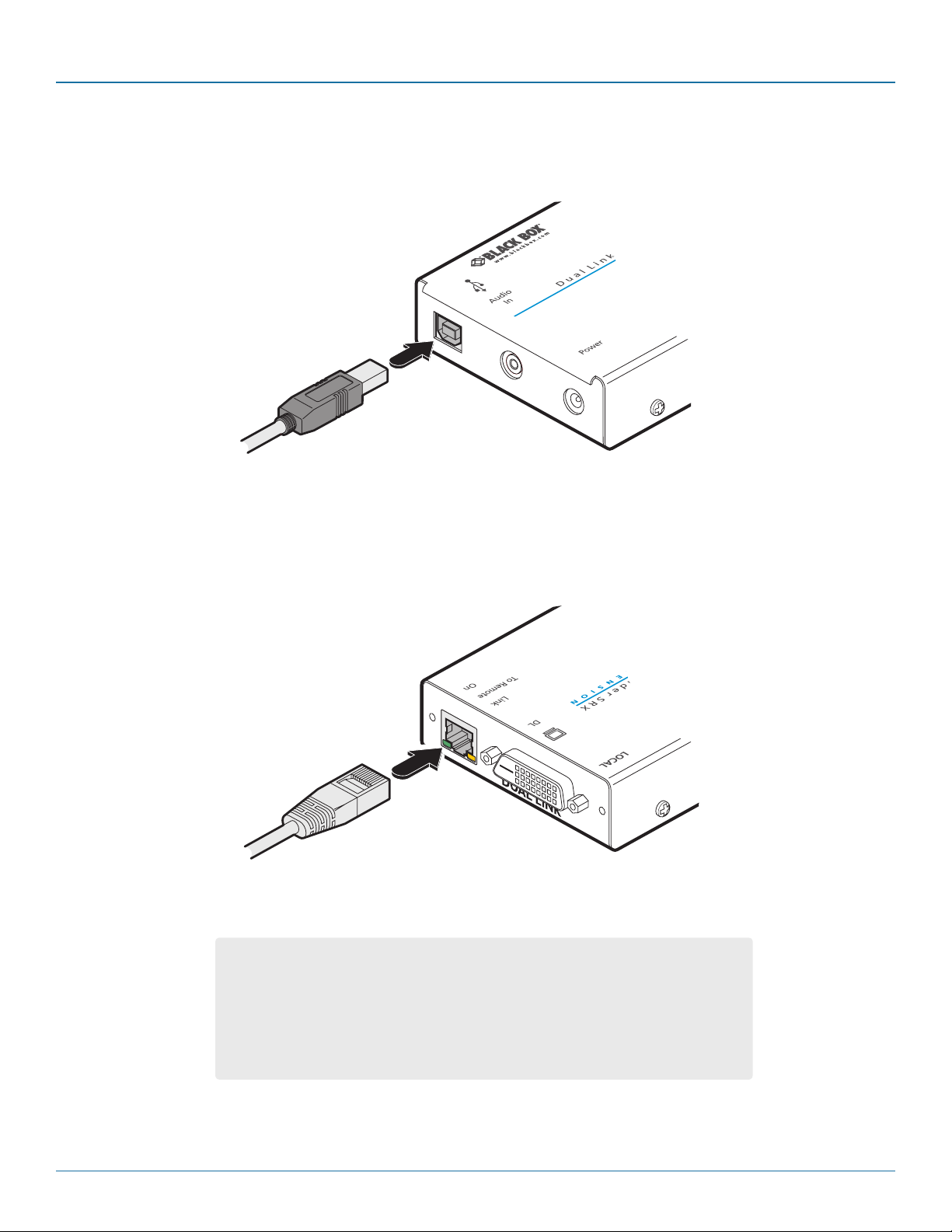
3.2.1.2 USB connection
1 Use the supplied USB cable to link the USB socket of the local module to a vacant USB socket on the computer as shown in
Figure 3-4:
Figure 3-4. Attaching the USB link cable
3.2.1.3 Link connection
1 Connect the link cable (see page 2 for cable advice) to the local module socket labeled TO REMOTE as shown in Figure 3-5:
Figure 3-5. Attaching the CATx link cable
IMPORTANT:
• ThisisNOTanEthernetportandmustnotbeconnectedtonetworkswitches
or any device other than the remote module.
• TheseextendersareNOTcompatiblewiththestandardDVI/USBSRX(single
link) versions. Where both types are being used in close proximity, take care
not to cross connect the local and remote modules between the two versions.
724-746-5500 | blackbox.com
Pa g e 11
Page 12
Dual Link DVI/USB Extender SRX
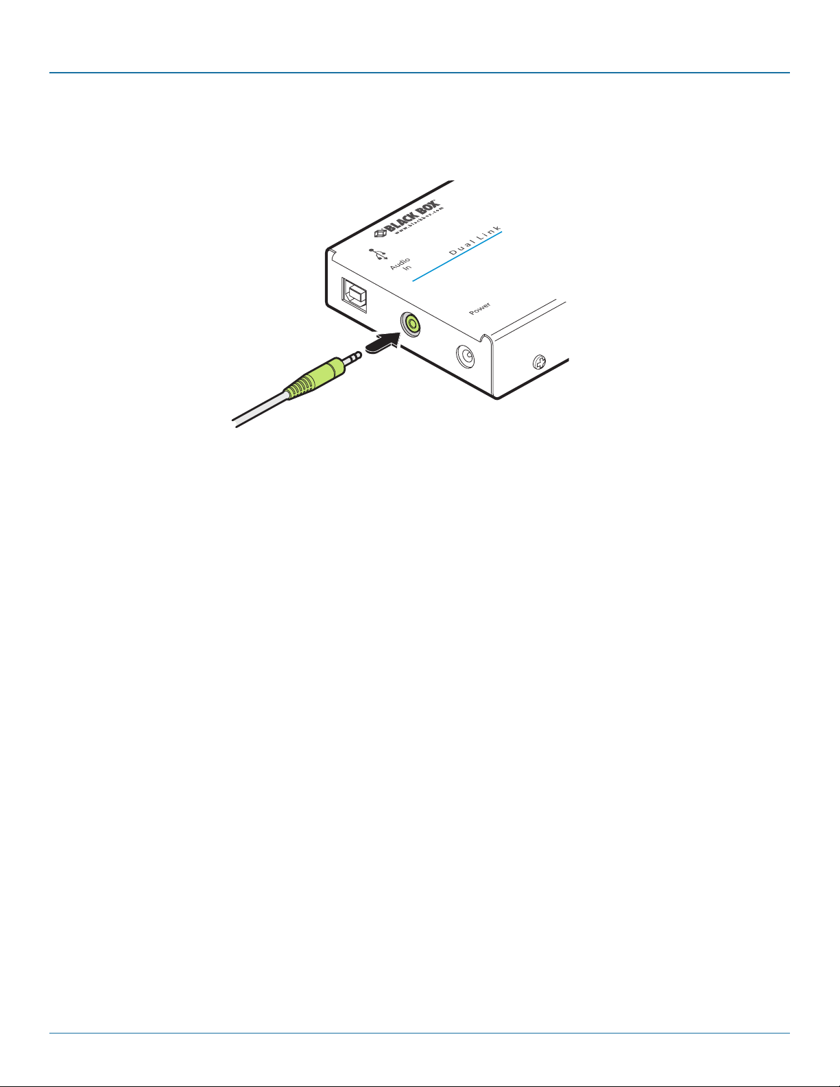
3.2.1.4 Audio connection
Optionally link a audio input to the local module using a 3.5mm audio cable.
Figure 3-6. Attaching an audio link to the local module
Page 12
724-746-5500 | blackbox.com
Page 13
Chapter 3: Installation
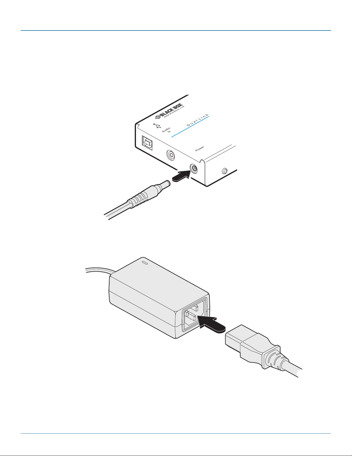
3.2.1.5 Power connection
1 Connect the output lead of the supplied power adapter to the socket labeled ‘POWER‘ on the local module as shown in Figure
3-7:
Figure 3-7. Attaching the power adapter connection to the local module
2 Insert the IEC connector of the separate power cord into the corresponding socket of the power adapter as shown in Figure
3-8:
Note: Please pay close attention to
the power related items within the
Safety information section.
Figure 3-8. Connecting the power cord to the adapter
3 Wait before connecting the other end of the power cord to a nearby mains outlet, until the remote module has been powered
up. The correct power up sequence is:
a) Remote module and screen > b) Local module > c) Computer.
724-746-5500 | blackbox.com
Page 13
Page 14
Dual Link DVI/USB Extender SRX
3.2.2 Connections at the remote module
3.2.2.1 Video connections
1 Place the remote module adjacent to the user location.
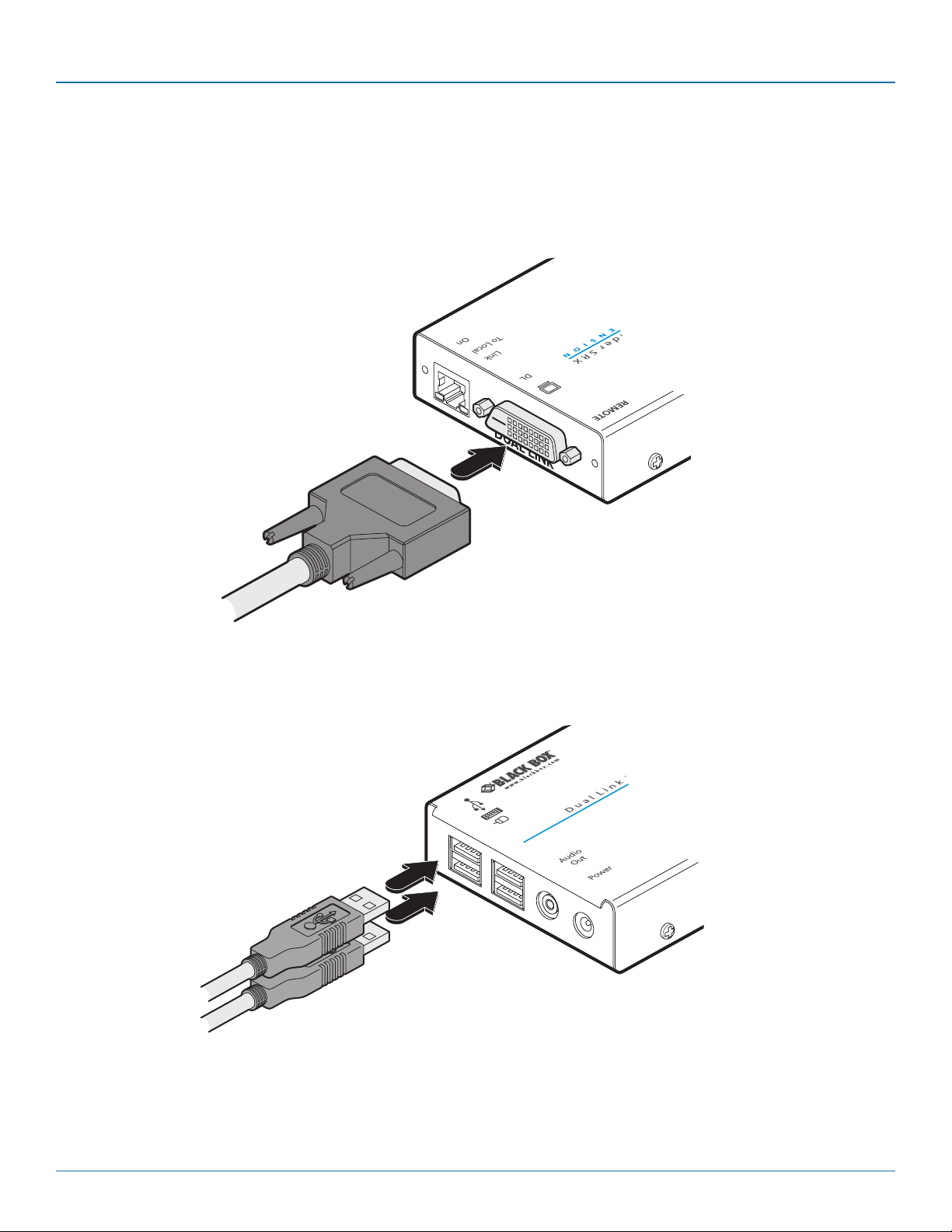
2. Connect the DVI/D lead from the video monitor to the DVI output socket of the remote module as shown in Figure 3-9:
Note: If dual link screen resolutions are
required, the DVI-D cables used at both the
local and remote modules must be dual link
types.
Figure 3-9. Attaching the DVI/D video monitor cable
3.2.2.2 USB connection
1 Connect the leads from the keyboard and mouse to two of the USB sockets on the remote module as shown in Figure 3-10:
Note: It is not important
which of the four sockets
are used.
Figure 3-10. Attaching the keyboard and mouse USB cables
IMPORTANT: The total current that may be drawn from the USB ports is 1.2A, which should be sufficient for a keyboard,
mouse (no more than 100mA each) and any two other devices (500mA maximum each). If more power for USB devices is
required, please use a powered USB hub.
2 Where other USB peripherals are also required, connect up to two other leads to the remaining USB sockets.
Page 14
724-746-5500 | blackbox.com
Page 15
Chapter 3: Installation
3.2.2.3 Link connections
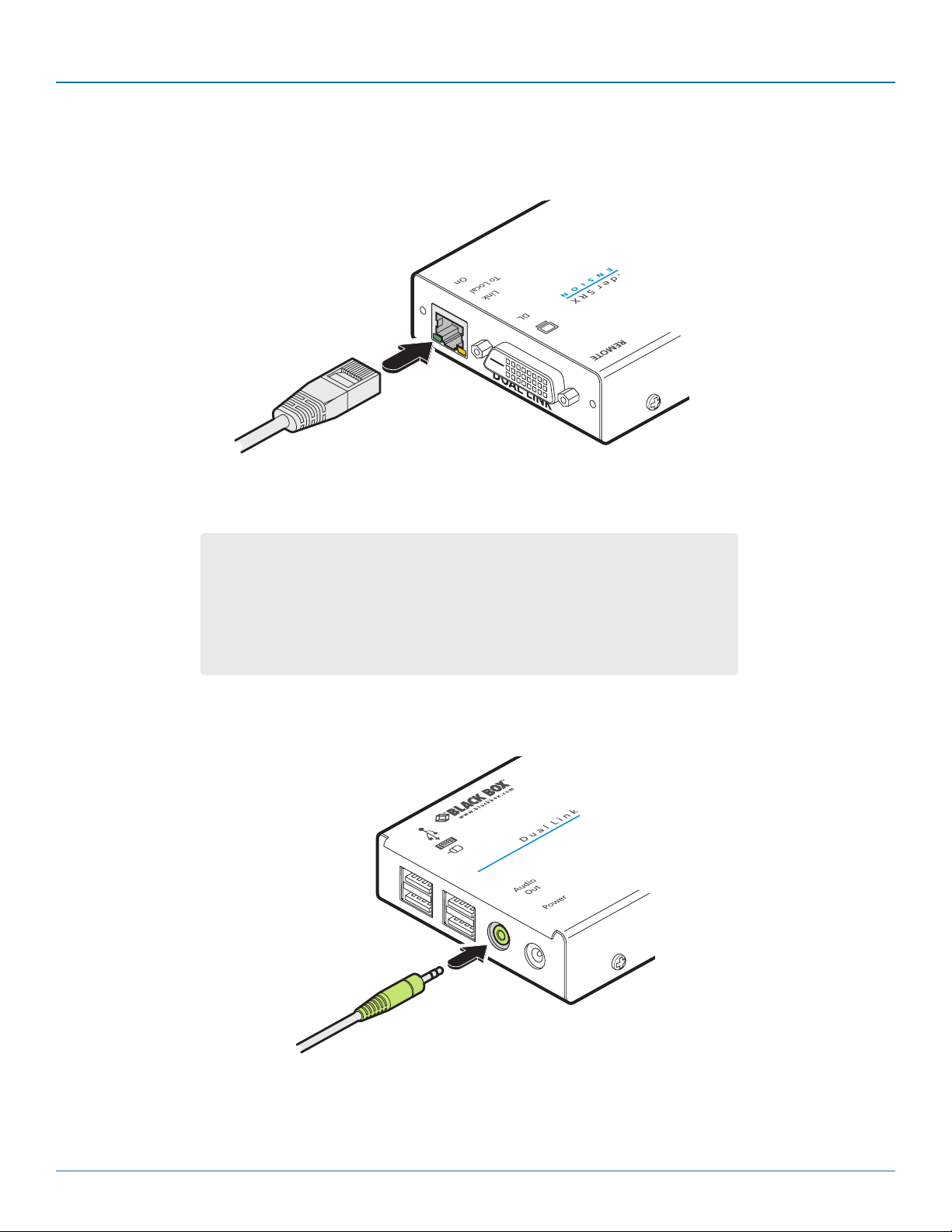
1 Connect the link cable (see page 2 for cable advice) to the remote module socket labeled TO LOCAL as shown in Figure 3-11:
Figure 3-11. Attaching the CATx link cable
IMPORTANT:
• ThisisNOTanEthernetportandmustnotbeconnectedtonetworkswitches
or any device other than the remote module.
• TheseextendersareNOTcompatiblewiththestandardDVI/USBSRX(single
link) versions. Where both types are being used in close proximity, take care
not to cross connect the local and remote modules between the two versions.
3.2.2.4 Speaker connection
Optionally link stereo speakers to the remote module using 3.5mm audio cable.
Figure 3-12. Attaching speakers to the remote module
724-746-5500 | blackbox.com
Page 15
Page 16
Dual Link DVI/USB Extender SRX
3.2.2.5 Power connection
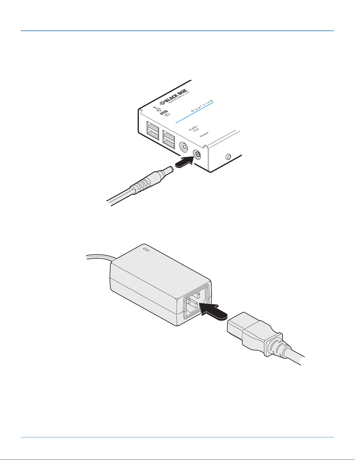
1 Connect the output lead of the supplied power adapter to the socket labeled ‘POWER‘ on the remote module as shown in
Figure 3-13:
Figure 3-13. Attaching the power adapter connection
2 Insert the IEC connector of the separate power cord into the corresponding socket of the power adapter as shown in Figure
3-14:
Note: Please pay close attention to
the power related items within the
Safety information section.
Figure 3-14. Connecting the power cord to the adapter
3 After all connections are made, power up the display screen and connect the other end of this power cord to a nearby mains
outlet. Then power up the local module and finally switch on the computer. This will allow each item, in order, to correctly discover the one immediately downstream.
Page 16
724-746-5500 | blackbox.com
Page 17

Chapter 4: Operation
4. Operation
4.1 General use
In use, the Dual Link DVI/USB Extender SRX modules should be transparent - the system and its peripherals should operate exactly
as normal, the only difference being that they are now up to 165 feet (50 meters) apart.
4.2 Video display (EDID) information
Extended Display Identification Data (or EDID) is an industry standard scheme which allows video monitors to declare their capabilities to the computer’s video adapter circuitry, allowing the latter to optimize their outputs accordingly. Since the widespread
adoption of the scheme, video adapters have become increasingly dependent on receiving relevant EDID information during startup, before they will output anything more than a rudimentary video signal.
Each time that the remote module is powered on, it attempts to read the EDID information from the connected DVI video monitor. If the attempt is successful, the information is transferred to the local module and stored within non-volatile memory. This is
information is then made available to the computer’s video adapter when required.
4.3 HDMI 1.3a operation
Using optional HDMI to DVI converter cables, the Dual Link DVI/USB Extender SRX modules can support HDMI video and
audio up to the 165MHz clock rate (1920 x 1080 at 60Hz, 24-bit colour).
Eight channels of HDMI audio are supported with sample sizes of 16, 20 or 24-bits at 32KHz, 44.1kHz, 48kHz, 88.2kHz,
96kHz, 176.4kHz, or 192kHz (simultaneously with the jack audio).
Note: The High-bandwidth Digital Content Protection (HDCP) and Consumer Electronics Control (CEC) schemes are not supported.
724-746-5500 | blackbox.com
Page 17
Page 18
Dual Link DVI/USB Extender SRX
LINK
TO REMOTE
ON
U S B S R X
N D E R
LINK
TO LOCAL
ON
U S B S R X
N D E R
4.4 Power and activity indicators
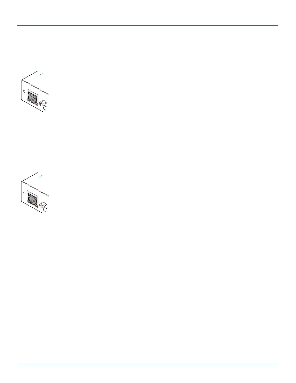
Each module provides two indicators to confirm power status and also feedback about the various input signals:
Local module
Green:
•Onwhenpowerispresent.
Yellow :
•OnwhenavalidsinglelinkDVIvideoinputsignalisbeingreceived
from the computer.
•Blinks(mostlyonwithshortoffperiods)whenavalidduallinkDVI
video input signal is being received from the computer.
• FlashesifnovalidDVIsignalisbeingreceivedfromthecomputer.
• OffiftheCATxlinkcableisdisconnected.
Remote module
Green:
•Onwhenpowerispresent.
Yellow:
•OnwhenavalidsinglelinkDVIvideoinputsignalisbeingreceived
from the local module.
•Blinks(mostlyonwithshortoffperiods)whenavalidduallinkDVI
video input signal is being received from the local module.
• FlashesiftheCATxlinkispresentbutnovalidDVIvideosignalis
being received from the local module.
• OffiftheCATxlinkcableisdisconnected.
Page 18
724-746-5500 | blackbox.com
Page 19

Appendices
Appendix A. Troubleshooting
If you experience problems when installing or using the modules, please check through this section for a possible solution. If your
problem is not listed here and you cannot resolve the issue, then please contact Black Box technical support.
No video image is displayed on the remote monitor
• Checktheyellowindicatorsonthelocalandremotemoduleswhilenokeysarepressedonthekeyboardandnomousemovements are being made:
LOCAL: If the yellow indicator is flashing*, then the video feed to the local module is not valid. Try connecting a DVI monitor
(preferably using the same DVI link cable as used with the local module) directly to the computer and check for a correct
image.
REMOTE: If the yellow indicator is flashing*, then the video feed via the link cable is not valid. If the link cable is long, try using
a short link cable temporarily to check for basic operation.
If the yellow indicators are off, then the link cable is not properly connected.
• CheckthatboththelocalandremoteendsoftheextenderareDualLinkDVI /USBExtenderSRXvariants.ThesinglelinkDVI/
USB SRX modules are not compatible.
Only single link resolutions are displayed
• Checkthatthevideocablesconnectedtothelocalandremotemodulesarebothspecificallyduallinktypes.
Video blanking is occurring on the remote display screen
• Checkthatthecorrecttypeandlengthoflinkcableisbeingused.Pleaseseethecableadvicegivenonpage2.
* Take care not to confuse the flash and blink codes used by the yellow indicators:
•A flash is when the yellow indicator shows a regular on/off cycle every second, to warn that there’s a video feed
problem.
•A blink is when the yellow indicator is mostly on with short off periods, to confirm that a valid dual link video signal is
present.
724-746-5500 | blackbox.com
Page 19
Page 20

Dual Link DVI/USB Extender SRX
Appendix B. Safety Information
• Foruseindry,oilfreeindoorenvironmentsonly.
• Donotusetolinkbetweenbuildings.
• Ensurethatthetwistedpairinterconnectcableisinstalledincompliancewithallapplicablewiringregulations.
• DonotconnecttheCATxlinkinterface(RJ45styleconnector)toanyotherequipment,particularlynetworkortelecommunica-
tions equipment.
• Warning–thepoweradaptercontainsliveparts.
• Nouserserviceablepartsarecontainedwithinthepoweradapter-donotdismantle.
• Plugthepoweradapterintoagroundedsocketoutletclosetotheunitthatitispowering.
• Replacethepoweradapterwithamanufacturerapprovedtypeonly.
• Donotusethepoweradapterifthepoweradaptercasebecomesdamaged,crackedorbrokenorifyoususpectthatitisnot
operating properly.
• Ifyouuseapowerextensioncordwiththeunits,makesurethetotalampereratingofthedevicespluggedintotheextension
cord do not exceed the cord’s ampere rating. Also, make sure that the total ampere rating of all the devices plugged into the
wall outlet does not exceed the wall outlet’s ampere rating.
• Donotattempttoservicetheunitsyourself.
• Theunitsandpowersuppliescangetwarminoperation–donotsituatetheminanenclosedspacewithoutanyventilation.
• Theunitsdonotprovidegroundisolationandshouldnotbeusedforanyapplicationsthatrequiregroundisolationorgalvanic
isolation.
Page 20
724-746-5500 | blackbox.com
Page 21

Black Box Tech Support: FREE! Live. 24/7.
Tech support the
way it should be.
Great tech support is just 60 seconds away at 724-746-5500 or blackbox.com.
®
About Black Box
Black Box Network Services is your source for an extensive range of networking and infrastructure products. You’ll find everything
from cabinets and racks and power and surge protection products to media converters and Ethernet switches all supported by
free, live 24/7 Tech support available in 60 seconds or less.
© Copyright 2015. Black Box Corporation. All rights reserved.
ACU5520A, rev. 1.0
®
724-746-5500 | blackbox.com
 Loading...