

Page 1

USER GUIDE
ACR500HDMI-T ACR500DP-T-R2
AGILITY
ZERO U
TRANSMITTER
24/7 TECHNICAL SUPPORT AT 1.877.877.2269 OR VISIT BLACKBOX.COM
Page 2

TRADEMARKS USED IN THIS MANUAL
Black Box and the Double Diamond logo are registered trademarks of BB Technologies, Inc.
Any other trademarks mentioned in this manual are acknowledged to be the property of the trademark owners.
NEED HELP?
LEAVE T HE TECH TO U S
LIVE 24/7
TECHNICAL
SUPPORT
1.877.877.2269
We‘re here to help! If you have any questions about your application
or our products, contact Black Box Tech Support at 877-877-2269
or go to blackbox.com and click on “Talk to Black Box.”
You’ll be live with one of our technical experts in less than 60 seconds.
2
1. 87 7. 877. 2 269 BLACKBOX.COM
Page 3

NEED HELP?
LEAVE T HE TECH TO U S
LIVE 24/7
TECHNICAL
SUPPORT
1.877.877.2269
FEDERAL COMMUNICATIONS COMMISSION AND INDUSTRY CANADA RADIO FREQUENCY INTERFERENCE
STATEMENTS
This equipment generates, uses, and can radiate radio-frequency energy, and if not installed and used properly, that is, in strict
accordance with the manufacturer’s instructions, may cause inter ference to radio communication. It has been tested and
found to comply with the limits for a Class A computing device in accordance with the specifications in Subpart B of Part 15 of
FCC rules, which are designed to provide reasonable protection against such interference when the equipment is operated in a
commercial environment. Operation of this equipment in a residential area is likely to cause interference, in which case the user
at his own expense will be required to take whatever measures may be necessary to correct the interference.
Changes or modifications not expressly approved by the party responsible for compliance could void the user’s authority to
operate the equipment.
This digital apparatus does not exceed the Class A limits for radio noise emis sion from digital apparatus set out in the Radio
Interference Regulation of Industry Canada.
Le présent appareil numérique n’émet pas de bruits radioélectriques dépassant les limites applicables aux appareils numériques
de la classe A prescrites dans le Règlement sur le brouillage radioélectrique publié par Industrie Canada.
Disclaimer:
Black Box Network Services shall not be liable for damages of any kind, including, but not limited to, punitive, consequential or
cost of cover damages, resulting from any errors in the product information or specifications set forth in this document and Black
Box Network Services may revise this document at any time without notice.
1. 87 7. 877. 2 269 BLACKBOX.COM
3
Page 4

NEED HELP?
LEAVE T HE TECH TO U S
LIVE 24/7
TECHNICAL
SUPPORT
1.877.877.2269
INSTRUCCIONES DE SEGURIDAD
(NORMAS OFICIALES MEXICANAS ELECTRICAL SAFETY STATEMENT)
1. Todas las instrucciones de seguridad y operación deberán ser leídas antes de que el aparato eléctrico sea operado.
2. Las instrucciones de seguridad y operación deberán ser guardadas para referencia futura.
3. Todas las advertencias en el aparato eléctrico y en sus instrucciones de operación deben ser respetadas.
4. Todas las instrucciones de operación y uso deben ser seguidas.
5. El aparato eléctrico no deberá ser usado cerca del agua—por ejemplo, cerca de la tina de baño, lavabo, sótano mojado o cerca
de una alberca, etc.
6. El aparato eléctrico debe ser usado únicamente con carritos o pedestales que sean recomendados por el fabricante.
7. El aparato eléctrico debe ser montado a la pared o al techo sólo como sea recomendado por el fabricante.
8. Servicio—El usuario no debe intentar dar servicio al equipo eléctrico más allá a lo descrito en las instrucciones de operación.
Todo otro servicio deberá ser referido a personal de servicio calificado.
9. El aparato eléctrico debe ser situado de tal manera que su posición no interfiera su uso. La colocación del aparato eléctrico
sobre una cama, sofá, alfombra o superficie similar puede bloquea la ventilación, no se debe colocar en libreros o gabinetes
que impidan el flujo de aire por los orificios de ventilación.
10. El equipo eléctrico deber ser situado fuera del alcance de fuentes de calor como radiadores, registros de calor, estufas u otros
aparatos (incluyendo amplificadores) que producen calor.
11. El aparato eléctrico deberá ser connectado a una fuente de poder sólo del tipo descrito en el instructivo de operación, o como
se indique en el aparato.
12. Precaución debe ser tomada de tal manera que la tierra fisica y la polarización del equipo no sea eliminada.
13. Los cables de la fuente de poder deben ser guiados de tal manera que no sean pisados ni pellizcados por objetos colocados
sobre o contra ellos, poniendo particular atención a los contactos y receptáculos donde salen del aparato.
14. El equipo eléctrico debe ser limpiado únicamente de acuerdo a las recomendaciones del fabricante.
15. En caso de existir, una antena externa deberá ser localizada lejos de las lineas de energia.
16. El cable de corriente deberá ser desconectado del cuando el equipo no sea usado por un largo periodo de tiempo.
17. Cuidado debe ser tomado de tal manera que objectos liquidos no sean derramados sobre la cubierta u orificios de ventilación.
18. Servicio por personal calificado deberá ser provisto cuando:
A: El cable de poder o el contacto ha sido dañado; u
B: Objectos han caído o líquido ha sido derramado dentro del aparato; o
C: El aparato ha sido expuesto a la lluvia; o
D: El aparato parece no operar normalmente o muestra un cambio en su desempeño; o
E: El aparato ha sido tirado o su cubierta ha sido dañada.
4
1. 87 7. 877. 2 269 BLACKBOX.COM
Page 5

NEED HELP?
LEAVE T HE TECH TO U S
LIVE 24/7
CONTENTS
TECHNICAL
SUPPORT
1.877.877.2269
CHAPTER 1: SPECIFICATIONS ..................................................................................................... 6
CHAPTER 2: WELCOME ..............................................................................................................7
CHAPTER 3: INSTALLATION ....................................................................................................... 8
Connections ................................................................................................................................................................................................8
Video link ..................................................................................................................................................................................................... 9
Network link ..............................................................................................................................................................................................10
USB and power connections ...................................................................................................................................................................11
CHAPTER 4: CONFIGURATION .................................................................................................. 12
Initial configuration .................................................................................................................................................................................. 12
Manual factory reset ................................................................................................................................................................................ 12
Browser-based configuration utility ....................................................................................................................................................... 13
Restoring a backup firmware image ....................................................................................................................................................... 14
Performing an upgrade ............................................................................................................................................................................ 15
CHAPTER 5: OPERATION .......................................................................................................... 16
Status indicators ...................................................................................................................................................................................... 16
Resetting ................................................................................................................................................................................................... 17
CHAPTER 6: FURTHER INFORMATION ...................................................................................... 18
Appendix A - Supported video modes .................................................................................................................................................... 18
Appendix B - Configuration pages .......................................................................................................................................................... 19
Appendix C - Dimensions ........................................................................................................................................................................ 29
Appendix D - Tips for success when networking Agility units ............................................................................................................. 30
Appendix E - Troubleshooting ................................................................................................................................................................. 32
Appendix F - Glossary ..............................................................................................................................................................................34
Appendix G - Open source licenses ........................................................................................................................................................ 37
SAFETY INFORMATION ............................................................................................................ 54
1. 87 7. 877. 2 269 BLACKBOX.COM
5
Page 6

CHAPTER 1: SPECIFICATIONS
Approvals: CE, FCC
Hardware Compatibility: All computers with DVI-D or DisplayPort digital video and USB interfaces
Software Compatibility: Operates with all known software and operating systems including
Windows®, Linux®, Unix®, BSD, all Sun® OS, all Mac® OS, NetWare®, etc.
Operating Temperature: 32 to 104°F (0 to 40°C)
NEED HELP?
LEAVE T HE TECH TO U S
LIVE 24/7
TECHNICAL
SUPPORT
1.877.877.2269
6
1. 87 7. 877. 2 269 BLACKBOX.COM
Page 7
NEED HELP?
LEAVE T HE TECH TO U S
LIVE 24/7
CHAPTER 2: WELCOME
TECHNICAL
SUPPORT
1.877.877.2269
Thank you for choosing the Black Box Agility family of high capacity digital extenders/switches. By encoding high quality video,
audio and Hi-Speed USB data into Internet Protocol (IP) messages, Agility units offer flexible ways to link peripherals and
systems via standard networks.
This guide covers the Agility Zero U unit, a highly compact dongle which can be attached to its host computer and transfer high
quality video (single link DisplayPort™ or HDMI™ according to the chosen model) and Hi-Speed USB signals across your network.
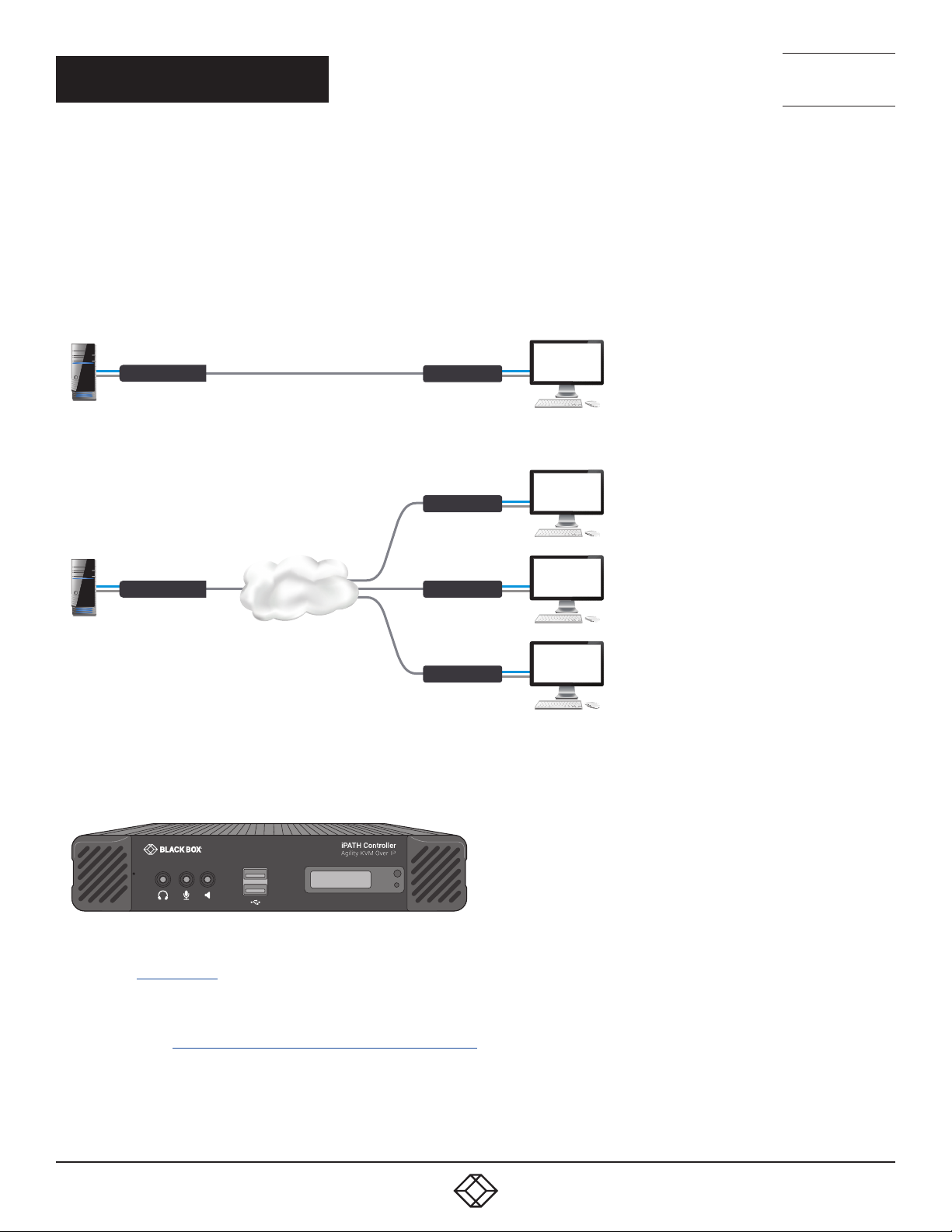
One-to-one conguration
The simplest conguration links one RX unit to a single TX unit, either by a direct link or over
much greater distances via a high speed network.
Agility Zero U TX
One-to-many conguration
Using multicast techniques, an unlimited
number of receivers* can receive video and
audio data streams from a single TX unit.
Agility Zero U TX
* A maximum of thirteen concurrent USB inputs
(via multiple RX units) are permitted to a single TX
unit.
Gigabit
Ethernet
Agility RX
Agility RX
Agility RX
Agility RX
AGILITY UNITS AND THE BLACK BOX IPATH AGILITY CONTROLLER
Where multiple Agility units are used on a network, we have developed the Black Box iPATH Agility Controller to allow
comprehensive and secure central control of all Agility units and users.
1
2
When using an Black Box iPATH Controller to configure Agility units, it is vital that all Agility units that you wish to locate and
control are set to their factory default settings. Otherwise they will not be located by the Black Box iPATH Controller. If necessary,
perform a factory reset on each Agility unit.
Note: If you are using one or more Agility Zero U Transmitter units within an installation managed by an Black Box iPATH
Controller, the Black Box iPATH Controller must be running firmware version 4.7 or above.
Please also see Appendix C - Tips for success when networking
1. 87 7. 877. 2 269 BLACKBOX.COM
7
Page 8
CHAPTER 3: INSTALLATION
CONNECTIONS
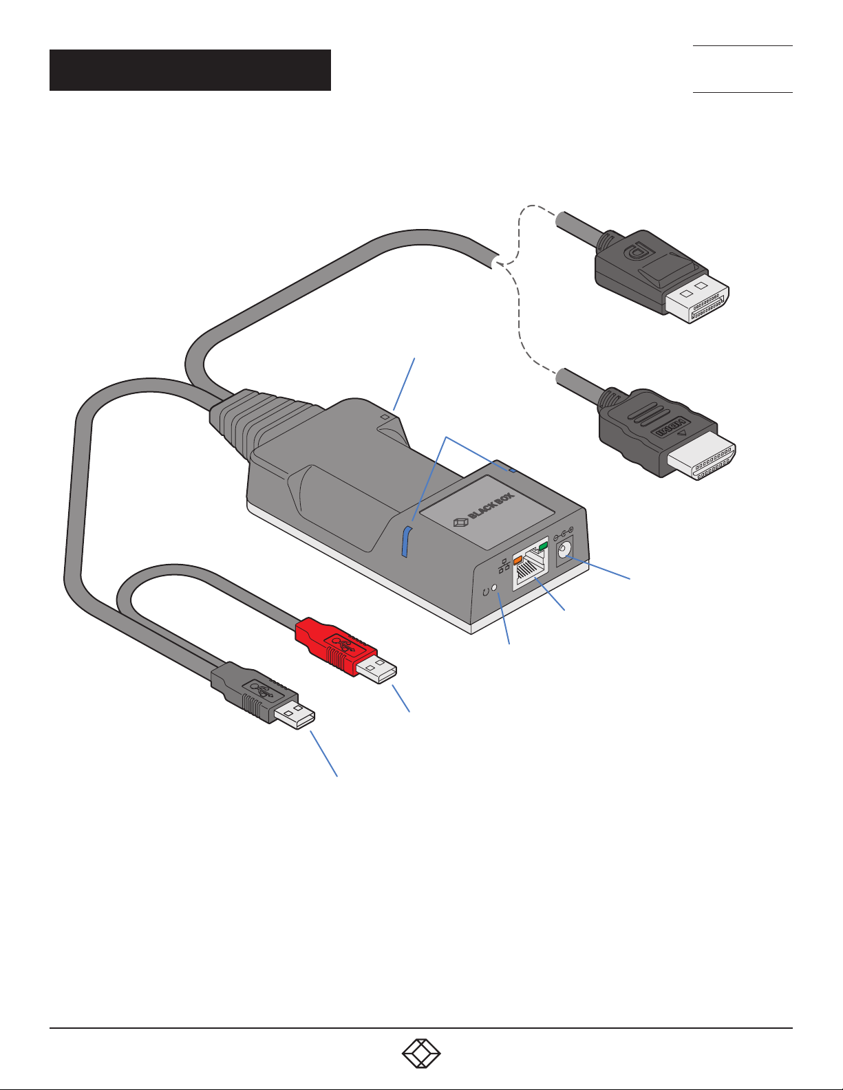
Installation involves linking the Agility Zero U unit to various ports on the
host computer, while the Agility RX unit is attached to your peripherals:
Cable tie
mounting slot
Status
indicators
NEED HELP?
LEAVE T HE TECH TO U S
LIVE 24/7
TECHNICAL
SUPPORT
1.877.877.2269
DisplayPort
or
HDMI
WWW.BLACKBOX.COM
WWW.BLACKBOX.COM
Reset
button
Red USB plug provides power only when
the external power adapter is not present
Black USB plug provides Hi-Speed USB signals
(plus power if the external power adapter is not
present)
Optional external
power input
Ethernet
port
8
1. 87 7. 877. 2 269 BLACKBOX.COM
Page 9
NEED HELP?
LEAVE T HE TECH TO U S
LIVE 24/7
TECHNICAL
SUPPORT
1.877.877.2269
VIDEO LINK
Each Agility Zero U unit is supplied with either a DisplayPort™or HDMI connector (model dependant). Video signals at pixel clocks
up to 300MHz (equivalent to a maximum resolution of 2560 x 1600 at 60Hz) are permissible. Two channel digital audio is also
supported via the video connector.
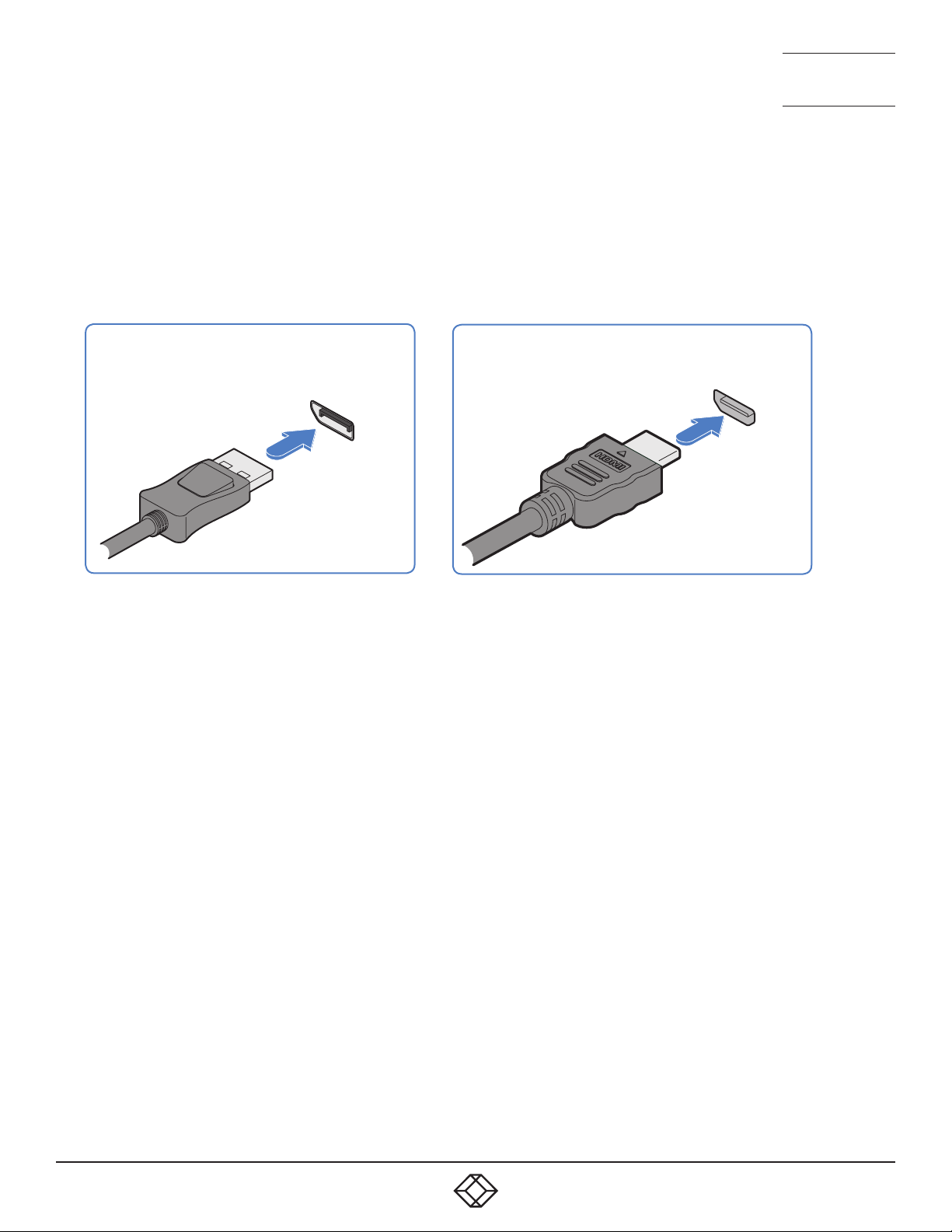
TO MAKE A VIDEO LINK
1 Connect the Agility Zero U video connector to the DisplayPort™ or HDMI socket of the host computer:
AGILITY ZERO U DP MODEL
Host computer
AGILITY ZERO U HDMI MODEL
DisplayPort
connector
Host computer HDMI
video port
SUPPORT FOR AUDIO
The Agility Zero U can derive its (digital) audio feed either from the USB connection or from the video link (i.e. embedded audio
within the DisplayPort/HDMI signal). In both cases, the digital audio is converted to analog as it is transferred to the receiver(s),
where it is output via their 3.5mm jack(s). The two audio sources are controlled from the System Configuration page of the
internal utility (see page 20) as follows:
• When the Enable Audio-1 option is checked, the Agility Zero U arranges a bi-directional audio stream with the host computer
via the USB connection.
• When the Enable Audio-2 option is checked, the EDID definition of the DisplayPort or HDMI connection will be altered to permit
a uni-directional audio stream via the video output. This allows the use of embedded audio, even when the video display itself
does not support audio.
Note: It is possible for both options to be enabled at the same time without issue.
1. 87 7. 877. 2 269 BLACKBOX.COM
9
Page 10
NEED HELP?
WWW.BLACKBOX.COM
WWW.BLACKBOX.COM
LEAVE T HE TECH TO U S
LIVE 24/7
TECHNICAL
SUPPORT
1.877.877.2269
NETWORK LINK
Agility transmitters and receivers can either be connected directly to each other or via a high speed network.
A single Gigabit Ethernet port is located on the front panel. For direct links via Ethernet cable, the length of cable should not
exceed 100 metres (328 feet). Network cables used for connections may be category 5, 5e, 6 or 7 twisted-pair cable. The Agility
Zero U unit has an auto-sensing capability on its network interfaces, so for direct point-to-point connections, no ‘crossover’
Ethernet cable is required.
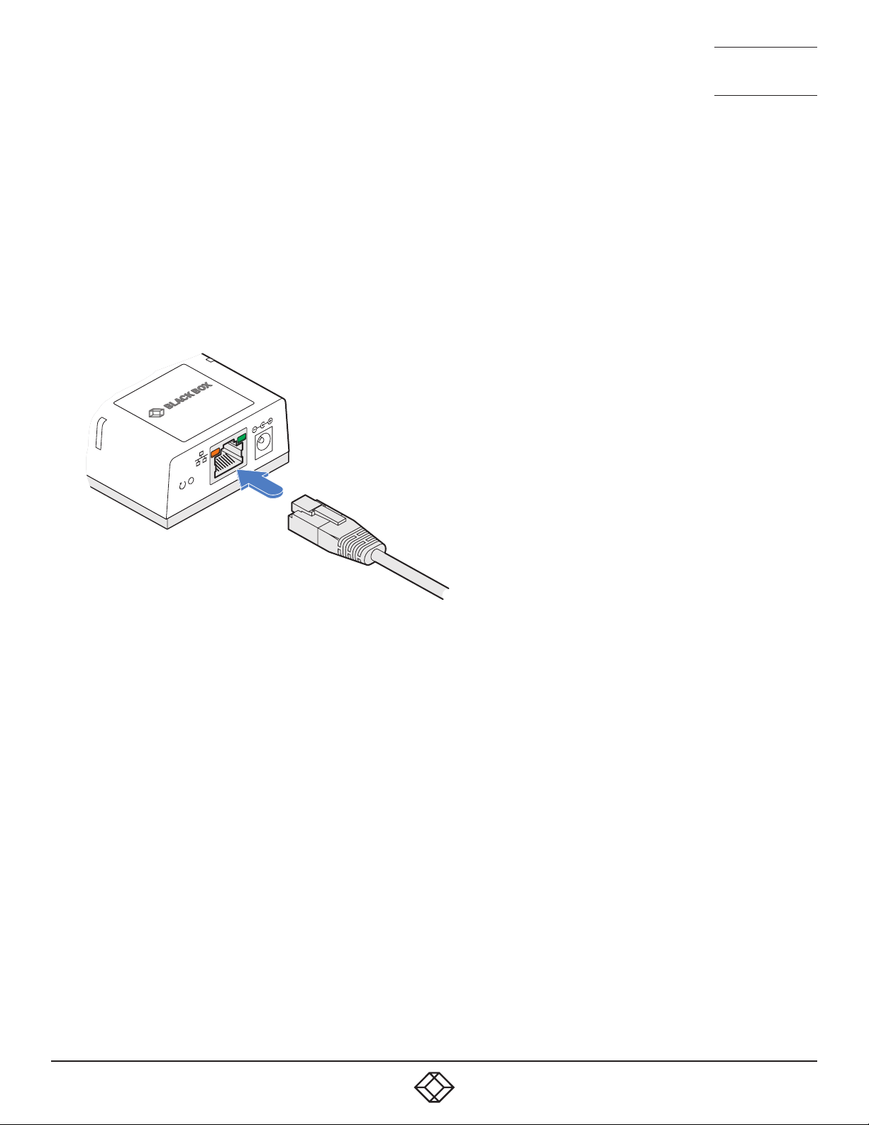
TO LINK THE AGILITY ZERO U UNIT
1 Connect a CAT 5, 5e, 6, or 7 cable to the Gigabit Ethernet socket on the front panel of the Agility Zero U unit.
CAT 5, 5e, 6, or 7 link either
directly from the other Agility unit or from a Gigabit
Ethernet switch
2 Connect the other end of the cable either directly to an Agility receiver or to a Gigabit Ethernet switch, as appropriate.
3 [For connections via a network] repeat steps 1 and 2 for the other Agility unit(s).
10
1. 87 7. 877. 2 269 BLACKBOX.COM
Page 11
NEED HELP?
WWW.BLACKBOX.COM
WWW.BLACKBOX.COM
LEAVE T HE TECH TO U S
LIVE 24/7
TECHNICAL
SUPPORT
1.877.877.2269
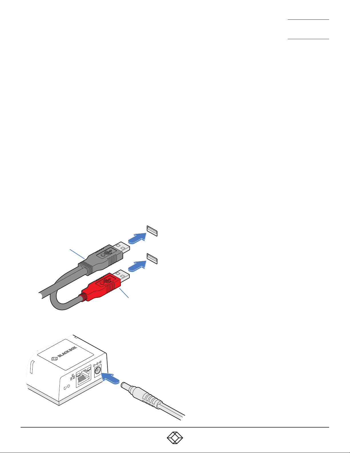
USB AND POWER CONNECTIONS
The Agility Zero U unit is designed to be as flexible as possible. It can either operate using an optional external power adapter
(see page 3) or derive all of its power from its two USB plugs. The main advantage offered by using an external power adapter
is that it allows the Agility Zero U unit to be active before the host computer; thus allowing a remote user to access the host’s
initial boot up and access the BIOS menu, when required.
If powered by USB only, then both the black and red USB plugs need to be connected.
If powered by external power adapter, only the black Hi-Speed USB plug needs to be connected, for signal purposes. Whenever,
the external power adapter is attached and operating, then power will be taken from it rather than the USB plugs. There is no
problem if the red USB plug remains connected while the power adapter is used.
This is summarized as follows:
Power Black Red
adapter USB USB Power sourcing behavior
û ü ü Power taken from both USB plugs.
ü ü û Power taken from power adapter only.
ü ü ü Power taken from power adapter only, unless it becomes unavailable, in which case power will
be taken from both USB plugs after a short interruption.
Note: The USB plugs do not operate as a seamless failover for the external power adapter; there will be a short interruption as
operation switches from one power source to the other.
Black USB plug
provides USB signals
(plus power if the external power adapter
is not present)
Host computer
USB ports
SUPPORT FOR AUDIO
The Agility Zero U can derive its (digital) audio feed
either from the USB connection or from the video
link (i.e. embedded audio within the DisplayPort/
HDMI signal). In both cases, the digital audio is
converted to analog as it is transferred to the
receiver(s), where it is output via their 3.5mm
jack(s). The two audio sources are controlled from
the System Configuration page of the internal utility
(see page 20) as follows:
Red USB plug provides power
only when the external power
adapter is not present
• When the Enable Audio-1 option is checked, the
Agility Zero U arranges a bi-directional audio
stream with the host computer via the USB
connection.
• When the Enable Audio-2 option is checked,
the EDID definition of the DisplayPort or HDMI
connection will be altered to permit a unidirectional audio stream via the video output.
This allows the use of embedded audio, even
From the optional
external power
adapter
when the video display itself does not support
audio.
Note: It is possible for both options to be enabled
at the same time without issue.
1. 87 7. 877. 2 269 BLACKBOX.COM
11
Page 12
NEED HELP?
WWW.BLACKBOX.COM
WWW.BLACKBOX.COM
LEAVE T HE TECH TO U S
LIVE 24/7
CHAPTER 4: CONFIGURATION
TECHNICAL
SUPPORT
1.877.877.2269
INITIAL CONFIGURATION
Agility units are designed to be as flexible as possible and this principle extends also to their configuration.
DIRECT LINKING
Where Agility transmitters and receivers are directly linked to each other, very little configuration action is required, provided that
they have their factory default settings in place. If the standard settings have been changed in a previous installation, you merely
need to perform a factory reset on each unit.
NETWORKED LINKING
Where Agility units are connected via networked links, you can either configure them individually, or configure them collectively
using an IPATH Agility Controller:
• Configuring networked Agility units individually - You need to specify the network addresses of the Agility units so that they
can locate each other. This is done by running the Browser-based configuration utility on a computer system linked to the
same network as the Agility units.
• Configuring Agility units collectively - The iPATH Agility Controller allows you to configure, control and coordinate any number
of Agility transmitters and receivers from a single application.
• IfyouareusingoneormoreAgilityZeroUtransmitterswithinaninstallationmanagedbyanIPATHAgilityController,the
IPATHAgilityControllermustberunningfirmwareversion4.12orabove.
IMPORTANT: When using IPATH to configure Agility units, it is vital that all units that you wish to locate and control are set to
their factory default settings. Otherwise they will not be located by the IPATH Agility Controller. If necessary, perform a factory
reset on each Agility unit.
MANUAL FACTORY RESET
A factory reset returns Agility Zero U unit to its default configuration. You can perform factory resets using the Browser-based
configuration utility or by using this direct manual method.
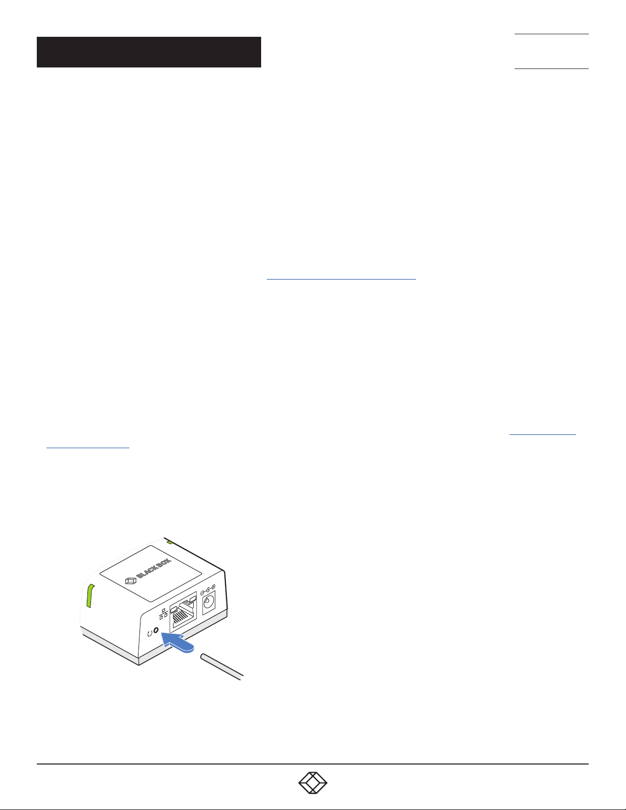
TO PERFORM A MANUAL FACTORY RESET
1 Power on the Agility Zero U unit.
2 Use a narrow implement (e.g. a straightened-out paper clip) to press-and-hold the recessed reset button on the front panel
for roughly fifteen seconds, until the indicators turn blue (Note: alternating red/green indications will occur during the fifteen
second period while the button is still pressed).
Use a straightened-out paper
clip to press the reset button
for roughly 5 seconds
3 Release the reset switch.
The indicators will remain blue for a short while (less than ten seconds) while Agility Zero U unit configures itself and should
then change to green if all connections are correct; or orange if one or more of the video, USB and/or network links are missing.
NOTE: If you are performing a factory reset and intend to disconnect the power immediately after the reset, you must wait at least 30 seconds after
you have released the reset button for it to complete the process.
12
1. 87 7. 877. 2 269 BLACKBOX.COM
Page 13
NEED HELP?
WWW.BLACKBOX.COM
WWW.BLACKBOX.COM
LEAVE T HE TECH TO U S
LIVE 24/7
TECHNICAL
SUPPORT
1.877.877.2269
BROWSER-BASED CONFIGURATION UTILITY
The browser-based configuration utility within all TX and RX units requires a network connection between the Agility Zero U
unit and a computer on the same network. The configuration utility allows you to perform many important functions. Please see
Appendix B.
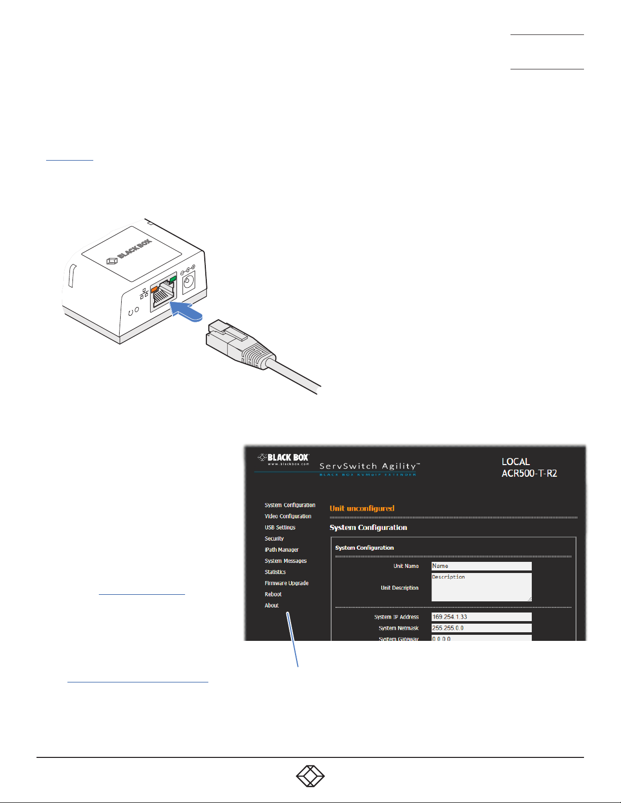
TO CONNECT A COMPUTER TO ACCESS THE CONFIGURATION UTILITY
1 Connect a CAT 5, 5e, 6, or 7 link cable to the network port on the front panel. The port automatically configures itself, so no
cross-over cable is required (but is supported if you do use one).
Temporary link from your
computer to the Agility Zero U
network port
2 Connect the other end of the link cable directly to the network port of your computer.
TO ACCESS THE BROWSER-BASED CONFIGURATION UTILITY
1 Temporarily connect the Agility Zero U
unit and your computer, as discussed
left.
2 Run a web browser on your computer and
enter the IP address of the Agility Zero U
unit:
169.25 4 .1.3 3
Note:IftheIPaddressofAgilityZeroU
unit has been changed and is not known,
providing it is appropriate to do so,
perform a manual factory reset to restore
the default address.
The opening page of the Agility
configuration utility should be displayed:
You can find further information about the
configuration pages later in this guide:
• Appendix B - Configuration pages
Use the menu options to choose the
required conguration page
1. 87 7. 877. 2 269 BLACKBOX.COM
13
Page 14
NEED HELP?
WWW.BLACKBOX.COM
WWW.BLACKBOX.COM
LEAVE T HE TECH TO U S
LIVE 24/7
TECHNICAL
SUPPORT
1.877.877.2269
RESTORING A BACKUP FIRMWARE IMAGE
The Agility Zero U unit retains a backup image of the previous firmware version in order to provide a fallback in case of any issues
with the primary image. The backup image has no video or USB functionality; once invoked, you will need to load an upgrade file
using the web interface or via an iPATH Agility Controller to load a new primary image - see Performing an upgrade (shown right).
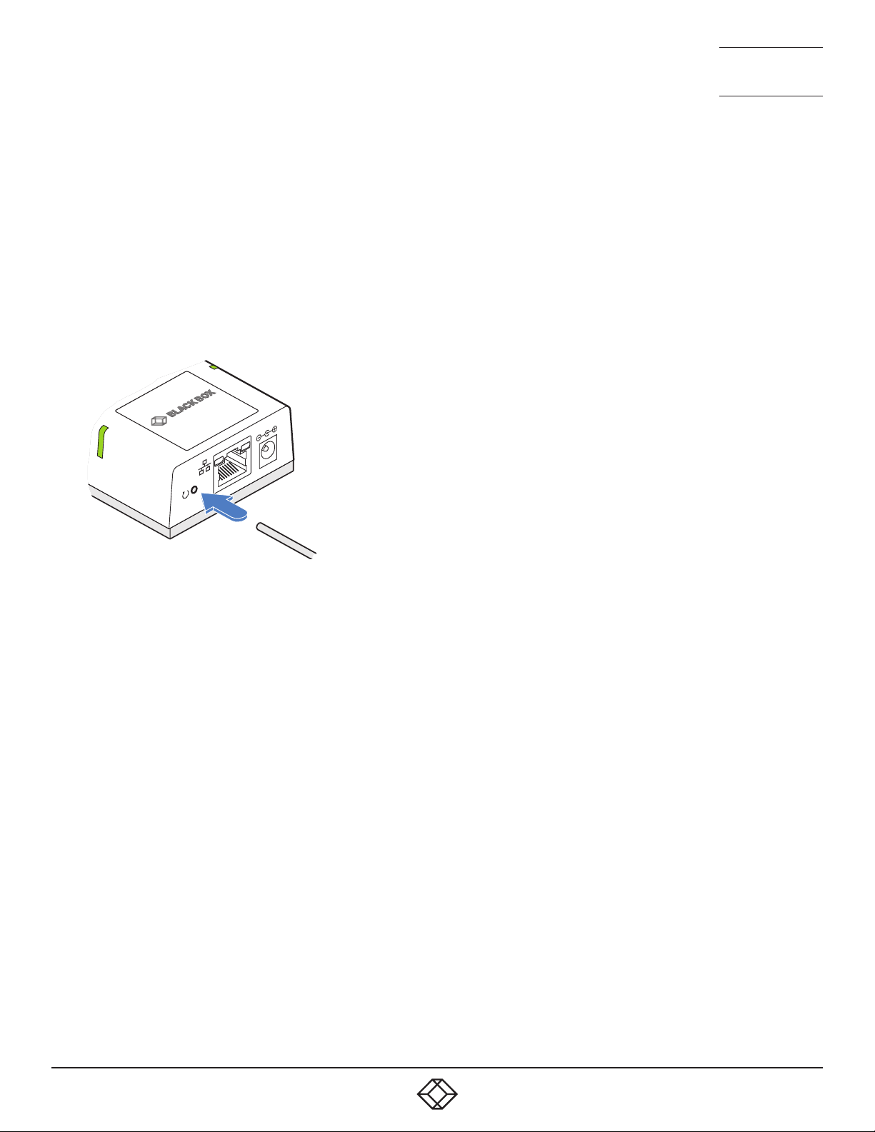
TO RESTORE THE BACKUP FIRMWARE IMAGE
1 Power on the Agility Zero U unit.
2 Use a narrow implement (e.g. a straightened-out paper clip) to press-and-hold the recessed reset button for roughly ten
seconds until the indicators flash green/red.
Use a straightened-out paper
clip to press the reset button
for roughly 10 seconds
3 Release the reset switch.
The Agility Zero U unit will switch to the backup firmware image. Once complete, Agility Zero U unit will then continually flash
green/red.
4 Perform an upgrade to reinstate a fresh primary firmware image - see next page.
14
1. 87 7. 877. 2 269 BLACKBOX.COM
Page 15

NEED HELP?
LEAVE T HE TECH TO U S
LIVE 24/7
TECHNICAL
SUPPORT
1.877.877.2269
PERFORMING AN UPGRADE
Agility Zero U units are flash upgradeable using the method outlined here. However, for larger installations we recommend that
you use the iPATH Agility Controller to upgrade multiple Agility units. When using the method below, the Agility Zero U unit will be
upgraded in sequence.
IMPORTANT: Upgrades should be performed equally on transmitters and receivers at the same time. Mixed firmware operation
may cause issues.
WARNING: During the upgrade process, ensure that power is not interrupted as this may leave Agility Zero U unit in an inoperable
state.
If the upgrade process is interrupted and fails, it may be necessary to switch to the backup firmware image in order to regain
operation. See previous page for details.
TO FIND THE LATEST UPGRADE FILES
Firmware files for the Agility Zero U units are available from the Black Box Support department.
Note: It is possible to downgrade the firmware. After installing the older firmware, perform a factory reset on each Agility unit in
order to clear the configuration file.
TO UPGRADE A SINGLE AGILITY ZERO U UNIT VIA THE NETWORK LINK
1 Download the latest upgrade file from Black Box.
2 Temporarily connect the Agility Zero U unit and a computer via a network (see Browser-based configuration utility section for
details).
3 Run a web browser on your computer and enter the IP address of the Agility Zero U unit to be upgraded.
4 Click the Firmware Upgrade link. Within the Firmware Upgrade page, click the Choose File button. In the subsequent file dialog,
locate the downloaded upgrade file - check that the file is correct for Agility Zero U unit being upgraded. The file contains a
single image.
5 Click the Upgrade Now button. A progress bar will be displayed (however, if your screen is connected to Agility Zero U unit
being upgraded then video may be interrupted) and the status indicators on Agility Zero U unit will flash while the upgrade is in
progress.
6 The indicators should stop flashing after roughly two minutes, after which Agility Zero U unit will automatically reboot itself.
The upgrade process is complete.
1. 87 7. 877. 2 269 BLACKBOX.COM
15
Page 16
NEED HELP?
LEAVE T HE TECH TO U S
LIVE 24/7
CHAPTER 5: OPERATION
In operation, many Agility installations require no intervention once configured. The TX and RX units take care of all connection
control behind the scenes so that you can continue to work unhindered.
TECHNICAL
SUPPORT
1.877.877.2269
STATUS INDICATORS
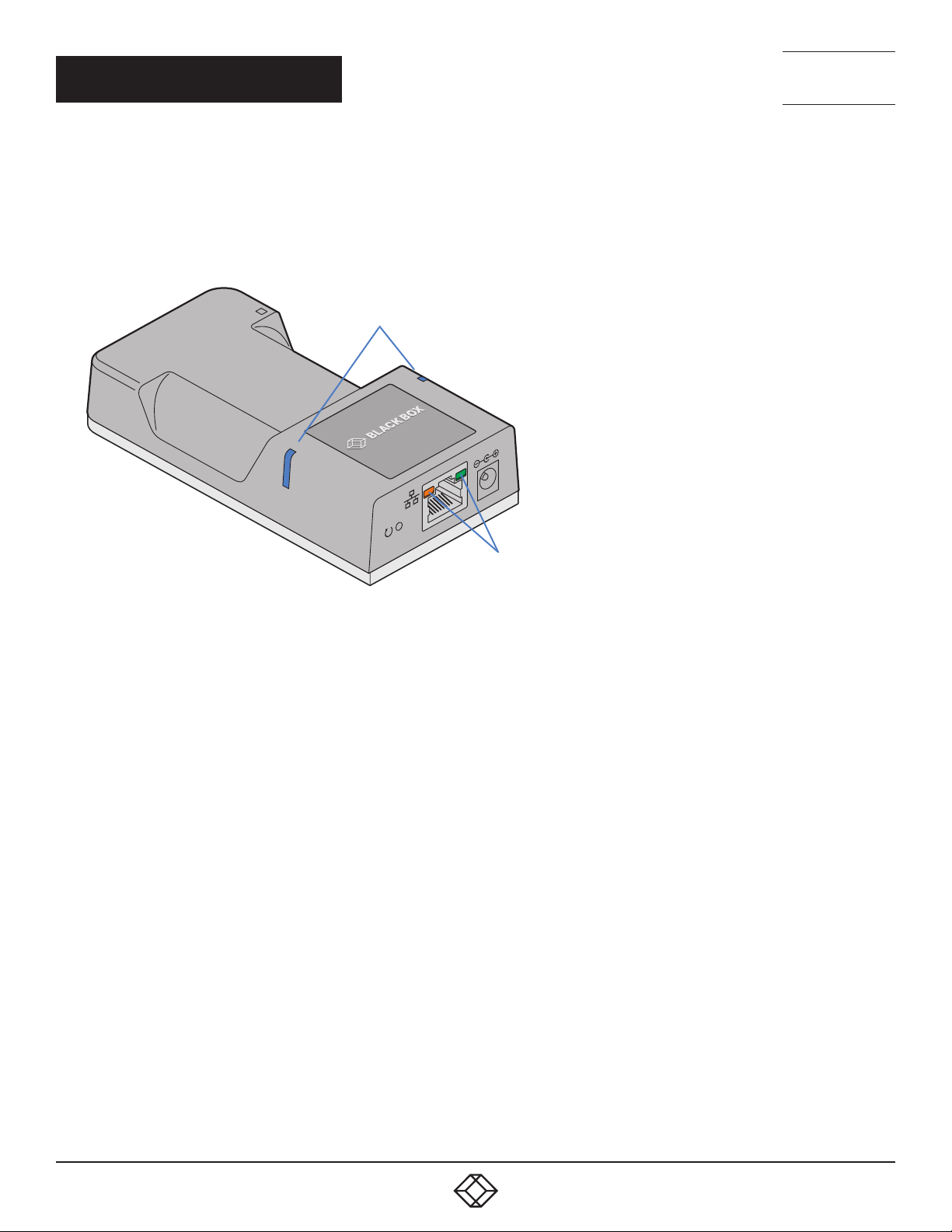
The two top panel indicators on the Agility Zero U unit provide a useful guide to operation:
Main status indicators
WWW.BLACKBOX.COM
WWW.BLACKBOX.COM
Network specic
indicators
MAIN STATUS INDICATORS
• Off No power
• Green Operating - Video, USB and network link all present
• Orange Operating - But video, USB and/or network link missing.
• Red (momentarily) Unit is booting up, or
(consistently) Unit has failed, try rebooting.
• Red/green flashing Unit is in backup mode.
• Blue Factory reset has been activated.
• Red/blue flashing Unit is in upgrade mode.
• Fast green flash Unit is in identify mode (see page 20).
NETWORK SPECIFIC INDICATORS
• Orange Off: No link On: Link established
• Green Off: No link Flashing: Network activity On: Quiescent link
16
1. 87 7. 877. 2 269 BLACKBOX.COM
Page 17
NEED HELP?
WWW.BLACKBOX.COM
WWW.BLACKBOX.COM
LEAVE T HE TECH TO U S
LIVE 24/7
TECHNICAL
SUPPORT
1.877.877.2269
RESETTING
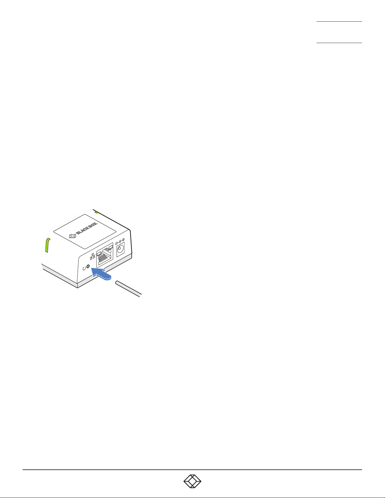
The recessed reset button provides a way to take control of the Agility Zero U if normal operation is affected. You will need a thin
implement, such as a straightened out paper clip to press and hold the button. Depending on when you release the button, one of
three functions will occur:
Required function Release time Indicators
To reboot to the primary firmware version less than 10s red
To boot to the backup firmware version* 10 to 14s green/red flash
To restore factory settings and reboot more than 15s blue
* The backup firmware version has no video or USB functionality. Once invoked, you will need to load an upgrade file to restore
normal operation - see page 14 .
TO RESET THE AGILITY ZERO U
1 Power on the Agility Zero U unit.
2 Use a narrow implement (e.g. a straightened-out paper clip) to press-and-hold the recessed reset button. The status indicators
will immediately turn red:
Use a straightened-out paper
clip to press the reset button
for roughly 10 seconds
3 Release the reset switch at the appropriate time (see the table above).
NOTE: If you are performing a factory reset and intend to disconnect the power immediately after the reset, you must wait at
least 30 seconds after you have released the reset button for it to complete the process.
1. 87 7. 877. 2 269 BLACKBOX.COM
17
Page 18

CHAPTER 6: FURTHER INFORMATION
APPENDIX A - Supported video modes
The following video modes are supported and can be automatically configured by the Agility
Zero U. If a recognized video mode cannot be found, contact Technical Support for help.
NEED HELP?
LEAVE T HE TECH TO U S
LIVE 24/7
TECHNICAL
SUPPORT
1.877.877.2269
cvt reduced 640 x 480 @ 60Hz
vesa 640 x 480 @ 60Hz
vesa 640 x 480 @ 72Hz
vesa 640 x 480 @ 75Hz
ibm 640 x 480 @ 75Hz
vesa 720 x 480 @ 60Hz
vesa 768 x 576 @ 60Hz
vesa 800 x 400 @ 60Hz
cvt reduced 800 x 600 @ 60Hz
vesa 800 x 600 @ 56Hz
vesa 800 x 600 @ 60Hz
vesa 800 x 600 @ 72Hz
vesa 800 x 600 @ 75Hz
cvt 1024 x 600 @ 60Hz
cvt reduced 1024 x 600 @ 60Hz
cvt reduced 1024 x 768 @ 60Hz
vesa 1024 x 768 @ 60Hz
vesa 1024 x 768 @ 70Hz
ibm 1024 x 768 @ 70Hz
vesa 1024 x 768 @ 75Hz
ibm 1024 x 768 @ 75Hz
vesa 1152 x 768 @ 60Hz
cvt reduced 1152 x 864 @ 60Hz
vesa 1152 x 864 @ 70Hz
vesa 1152 x 864 @ 75Hz
cvt 1280 x 720 @ 60Hz
vesa 1280 x 720 @ 60Hz
vesa 1280 x 768 @ 60Hz
vesa reduced 1280 x 786 @ 60Hz
vesa 1280 x 786 @ 75Hz
vesa 1280 x 786 @ 85Hz
vesa 1280 x 800 @ 60Hz
cvt reduced 1280 x 960 @ 60Hz
vesa 1280 x 960 @ 60Hz
cvt reduced 1280 x 1024 @ 60Hz
vesa 1280 x 1024 @ 60Hz
ibm 1280 x 1024 @ 67Hz
vesa 1280 x 1024 @ 75Hz
cvt reduced 1360 x 768 @ 60Hz
vesa 1360 x 768 @ 60Hz
vesa 1366 x 768 @ 60Hz
vesa reduced 1366 x 768 @ 60Hz
vesa 1400 x 1050 @ 60Hz
vesa reduced 1400 x 1050 @ 60Hz
vesa 1440 x 900 @ 60Hz
vesa 1440 x 960 @ 60Hz
cvt reduced 1600 x 900 @ 60Hz
vesa reduced 1600 x 900 @ 60Hz
cvt reduced 1600 x 1200 @ 60Hz
vesa 1600 x 1200 @ 60Hz
vesa 1680 x 1050 @ 60Hz
vesa reduced 1680 x 1050 @ 60Hz
vesa 1920 x 540 @ 60Hz
cvt reduced 1920 x 1080 @ 50Hz
cvt 1920 x 1080 @ 50Hz
vesa 1920 x 1080 @ 60Hz
vesa reduced 1920 x 1200 @ 60Hz
vesa 1920 x 1440 @ 60Hz
vesa 2048 x 768 @ 60Hz
vesa 2048 x 1080 @ 60Hz
vesa 2048 x 1152 @ 60Hz
vesa 2048 x 1536 @ 60Hz
vesa 2048 x 2048 @ 60Hz
vesa 2560 x 1080 @ 60Hz
vesa 2560 x 1080 @ 60Hz
vesa 2560 x 1440 @ 60Hz
vesa 2560 x 1600 @ 60Hz
vesa 2560 x 2048 @ 50Hz
vesa 3440 x 1440 @ 50Hz
sun 1024 x 768 @ 77Hz
sun 1152 x 900 @ 66Hz
sun 1152 x 900 @ 76Hz
sun 1024 x 1024 @ 61Hz
sun 1280 x 1024 @ 67Hz
sun 1280 x 1024 @ 76Hz
Note: Other video modes may also be supported.
18
1. 87 7. 877. 2 269 BLACKBOX.COM
Page 19

NEED HELP?
LEAVE T HE TECH TO U S
LIVE 24/7
TECHNICAL
SUPPORT
1.877.877.2269
APPENDIX B - Conguration pages
This section covers the browser-based configuration utility for the Agility Zero U unit. The pages are titled as follows:
• System Configuration • System Messages
• Video Configuration • Statistics
• USB Settings • Firmware Upgrade
• Security • Reboot
• IPATH Manager • About
1. 87 7. 877. 2 269 BLACKBOX.COM
19
Page 20
SYSTEM CONFIGURATION
NEED HELP?
LEAVE T HE TECH TO U S
LIVE 24/7
TECHNICAL
SUPPORT
1.877.877.2269
To get here
1 Connect your computer to the network port on the front panel.
2 Run a web browser and enter the IP address of the unit. If the address is
unknown, perform a manual factory reset to http://169.254.1.33
3 If necessary, click the System Conguration link.
20
1. 87 7. 877. 2 269 BLACKBOX.COM
Page 21

NEED HELP?
LEAVE T HE TECH TO U S
LIVE 24/7
TECHNICAL
SUPPORT
1.877.877.2269
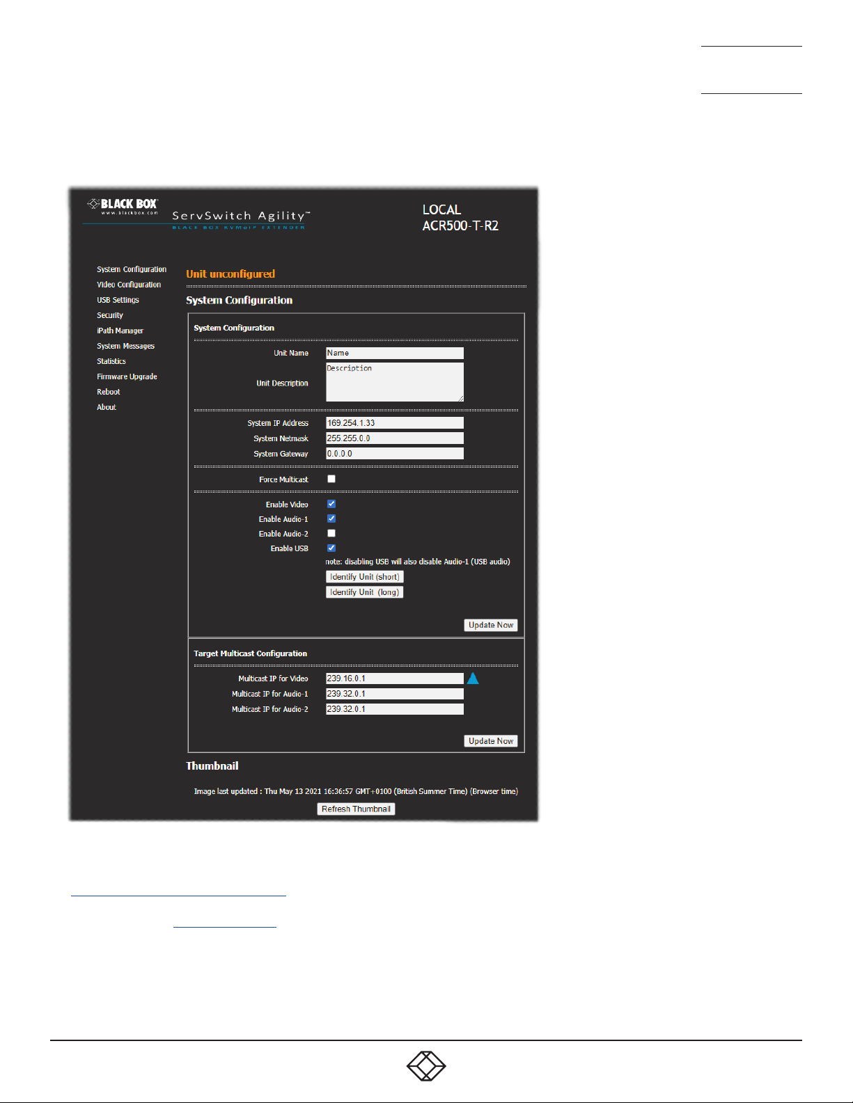
Unit Name
Name details that you can alter to distinguish this unit from all others. The name entered here will be read by IPATH units (if used) for administration
purposes.
Unit Description
Allows you to optionally add a description of the unit, such as its location. Useful when many Agility units are being used.
System port
This section determines the IP Address, Netmask and Gateway details for the Gigabit Ethernet port located on the front panel. The default IP address is 169.254.1.33 which is the zero cong IP address that allows Agility Zero U unit to work immediately in point-to-point mode. You are recommended to change this to an appropriate address in the private IP range 192.168.xxx.xxx
The default netmask is 255.255.0.0. If you change the IP address to the private range, you are recommended to change this to 255.255.255.0 The
default gateway address is 0.0.0.0
Force Multicast
By default, the Agility Zero U unit will use unicast transmission when only a single RX is connected. This would then be upgraded to multicast when
one or more other RX units are added. By ticking this option, the Agility Zero U unit will always use multicast. This option should be ticked for most
installations as it provides the most efcient way to deliver video and audio to multiple destinations.
Enable options
These checkboxes allow you to determine which peripheral options will be used: Video, digital audio and USB.
• When the Enable Audio-1 option is checked, the Agility Zero U arranges a bi-directional audio stream with the host computer via the USB connec-
tion.
• When the Enable Audio-2 option is checked, the EDID denition of the DisplayPort or HDMI connection will be altered to permit a uni-directional
audio stream via the video output. This allows the use of embedded audio, even when the video display itself does not support audio.
Note: It is possible for both options to be enabled at the same time without issue.
Identify unit
When clicked, these buttons cause the top indicators to flash to assist with identifying the Agility Zero U unit within a rack.
• The Identify Unit (short) button flashes the indicators for ve seconds.
• The Identify Unit (long) button flashes the indicators for one hour but can be overridden by clicking the Identify Unit (short) button.
Target Multicast Conguration
This option allows you to congure an IP address to which this transmitter can send multicast video and audio data, and from which multiple receivers can tap into it.
Note: The multicast addresses for each service endpoint must be unique across the whole Agility installation.
Update Now
Click to save and implement your changes.
Thumbnail
The Thumbnail shows snap shots of the video feeds that are connected and reports the video resolutions/color depths that have been detected.
Click the Refresh Thumbnail button to update. Note:ForsecurityreasonsthethumbnailimageisnotdisplayedwhentheAgilityZeroUunitisunder
IPATHcontrol.
1. 87 7. 877. 2 269 BLACKBOX.COM
21
Page 22
VIDEO CONFIGURATION
NEED HELP?
LEAVE T HE TECH TO U S
LIVE 24/7
TECHNICAL
SUPPORT
1.877.877.2269
To get here
1 Connect your computer to the network port on the front panel.
2 Run a web browser and enter the IP address of the unit. If the address is
unknown, perform a manual factory reset to http://169.254.1.33
3 Click the Video Conguration link.
22
1. 87 7. 877. 2 269 BLACKBOX.COM
Page 23

NEED HELP?
LEAVE T HE TECH TO U S
LIVE 24/7
TECHNICAL
SUPPORT
1.877.877.2269
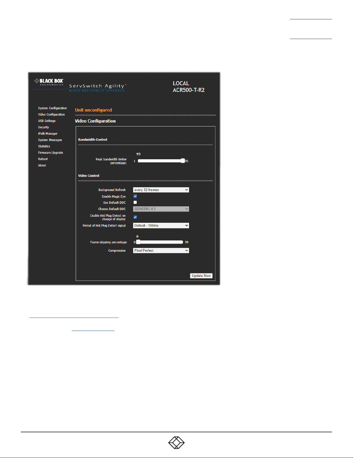
Peak bandwidth limiter percentage
The Agility Zero U unit will employ a ‘best effort’ strategy in sending video and other data over the IP network. This means it will use as much of the
available network bandwidth as necessary to achieve optimal data quality, although typically the Agility Zero U unit will use considerably less than
the maximum available. In order to prevent the Agility Zero U unit from ‘hogging’ too much of the network capacity, you can reduce this setting to
place a tighter limit on the maximum bandwidth permissible to the Agility Zero U unit. Range: 0 to 95%.
Background Refresh
The Agility Zero U unit sends portions of the video image only when they change. In order to give the best user experience, the Agility Zero U unit
also sends the whole video image, at a lower frame rate, in the background. The Background Refresh parameter controls the rate at which this
background image is sent. The default value is ‘every 32 frames’, meaning that a full frame is sent in the background every 32 frames. Reducing
this to ‘every 64 frames’ or more will reduce the amount of bandwidth that the Agility Zero U unit consumes. On a high-trafc network this parameter should be reduced in this way to improve overall system performance. Options: every 32 frames, every 64 frames, every 128 frames, every 256
frames or disabled.
Enable Magic Eye
This feature, enabled as standard, aims to reduce the effect of dithering - a technique used by some graphics cards to improve the perceived quality
and color depth of images by diffusing or altering the color of pixels between video frames. The Magic Eye feature increases the frame rate and
eliminates unnecessary network trafc by ignoring the color dithering where it occurs. If the video source is not noisy or dithered then you can
switch off Magic Eye to enable full color accuracy. Magic Eye mode can remain enabled without penalty for video that does not have dither or noise.
Use Default DDC and Choose Default DDC
When the UseDefaultDDC option is unticked, Agility will use the EDID that is reported by the monitor connected to the receiver unit. However, if you
tick the UseDefaultDDC option, you can then select from a range of preset video resolutions from the ChooseDefaultDDC drop down box. Once
selected, Agility Zero U unit will report itself to prefer this video mode.
Enable Hot Plug Detect on change of display
When this option is ticked, every time the monitor is changed at the receiver unit, hot plug state changes are sent to the graphics card of the PC attached to the Agility Zero U unit as if a screen has just been attached.
Period of Hot Plug Detect signal
This is the length of time that the hot-plug detect signal is de-asserted. The default of 100ms is sufcient for the majority of HDMI/DP++ graphics
cards, however, a small minority may need to be given a longer a period.
Frame skipping percentage
Frame Skipping involves ‘missing out’ video frames between those captured by the Agility Zero U unit. For video sources that update only infrequently
or for those that update very frequently but where high delity is not required, frame skipping is a good strategy for reducing the overall bandwidth
consumed by the system. Range: 0 to 100%.
Compression
Determines the (AFZ and AFZ+) compression method used for video transmission. Choices are:
• ‘Pixel perfect’ - only uses pixel perfect AFZ,
• ‘Adaptive’ - guarantees frame rate, builds to pixel perfect,
• ‘Smoothest video’ - forces the maximum compression, or
• ‘Advanced’ - allows you to choose a xed compression mode:
• ‘AFZonly(pixelperfect),
• ‘AFZ+Minimumcompression’,
• ‘AFZ+Middlecompression’, or
• ‘AFZ+Maximumcompression’.
1. 87 7. 877. 2 269 BLACKBOX.COM
23
Page 24
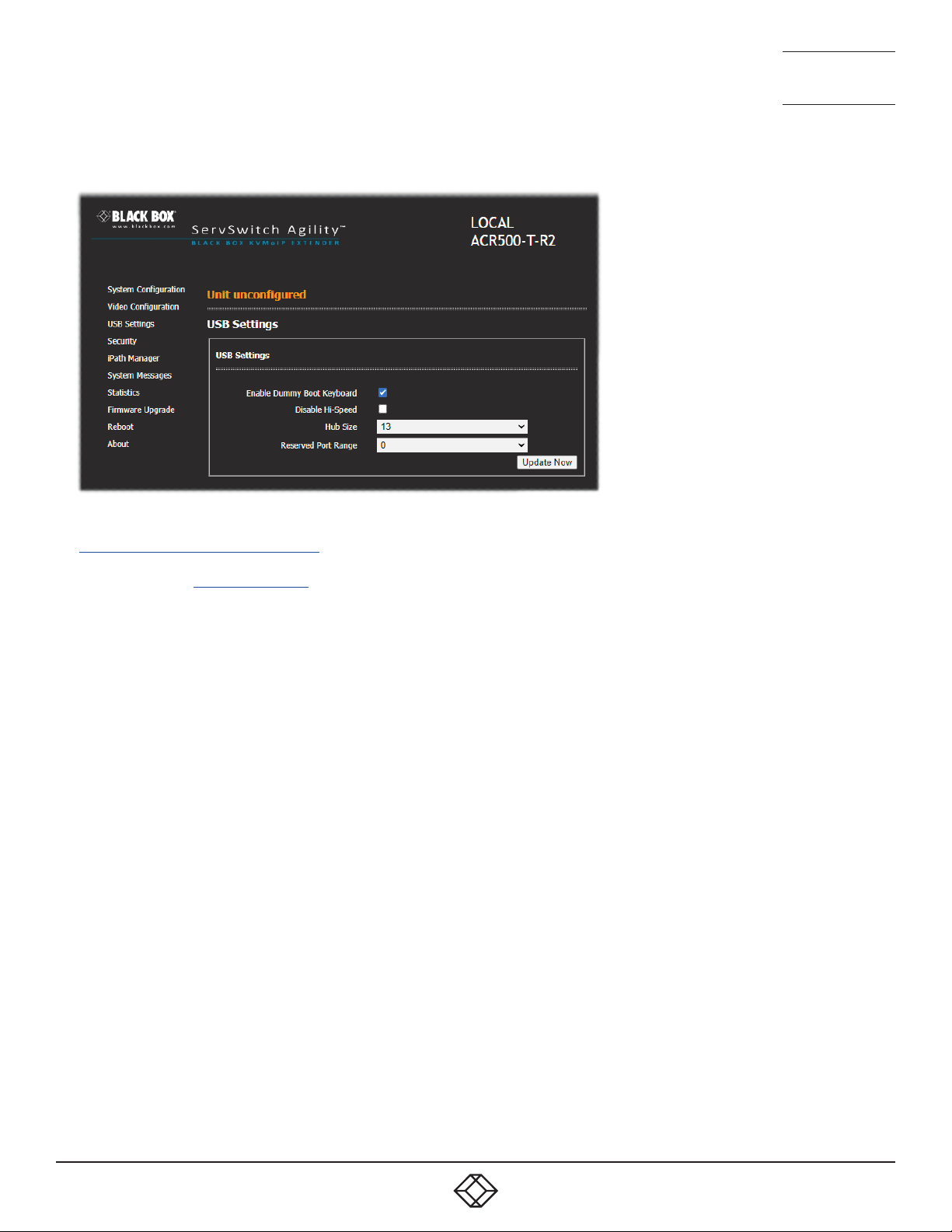
USB SETTINGS
NEED HELP?
LEAVE T HE TECH TO U S
LIVE 24/7
TECHNICAL
SUPPORT
1.877.877.2269
To get here
1 Connect your computer to the network port on the front panel.
2 Run a web browser and enter the IP address of the unit. If the address is
unknown, perform a manual factory reset to http://169.254.1.33
3 Click either the USB Settings link.
Enable Dummy Boot Keyboard
When ticked, Agility Zero U unit will report a virtual dummy boot keyboard to the attached PC to ensure that a keyboard is always reported when the
PC boots up. The dummy boot keyboard uses one of the 13 USB endpoints, therefore if all 13 endpoints are required elsewhere for USB devices (or a
KVM switch only supports two HID devices) then it can be disabled by deselecting this option. See also Reserved Port Range below.
Disable Hi-Speed
This option allows you to force the system to run at the low/full USB speed of 12Mb/s, thus forcing USB 2.0 Hi-Speed devices to adapt to the lower
rate.
Hub Size
Using this option you can select whether Agility Zero U unit should report itself as a 13 or a 7 port USB hub. Some USB hosts are only able to support 7 port USB hubs. If this option is set to 7, then only 7 USB devices are supported by the PC.
Reserved Port Range
For some devices, e.g. touch screens, you may wish to ensure that they are always reported to the same USB port number so that the USB driver
will always nd the device. This option allows you reserve up to 8 ports for certain devices. At the RX unit, the devices are assigned to the reserved
ports. If a port reservation is to be applied, then the dummy boot keyboard should be disabled. The default value for this option is ‘0’, i.e. disabled.
24
1. 87 7. 877. 2 269 BLACKBOX.COM
Page 25
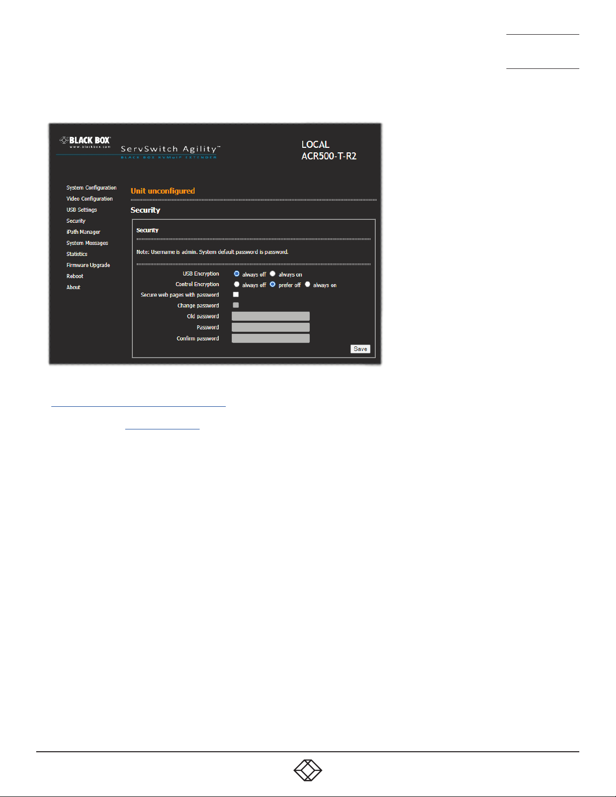
SECURITY
NEED HELP?
LEAVE T HE TECH TO U S
LIVE 24/7
TECHNICAL
SUPPORT
1.877.877.2269
To get here
1 Connect your computer to the network port on the front panel.
2 Run a web browser and enter the IP address of the unit. If the address is
unknown, perform a manual factory reset to http://169.254.1.33
3 Click either the Security link.
USB Encryption
This setting determines whether encryption should be applied to the USB data passed across the link. Note that video data is never encrypted.
Control Encryption
This setting determines whether encryption should be applied to the control data passed across the link. The “Prefer off” setting means that control
encryption is enabled if the receiver at the other end of the link has “always on” selected, otherwise it is disabled. Note: video data is never encrypt-
ed.
Secure web pages with password
When ticked, this option enables https security so that the conguration pages are only accessible to the admin user with a password.
Change/conrm password
These options allow you to change the admin password for the system.
1. 87 7. 877. 2 269 BLACKBOX.COM
25
Page 26
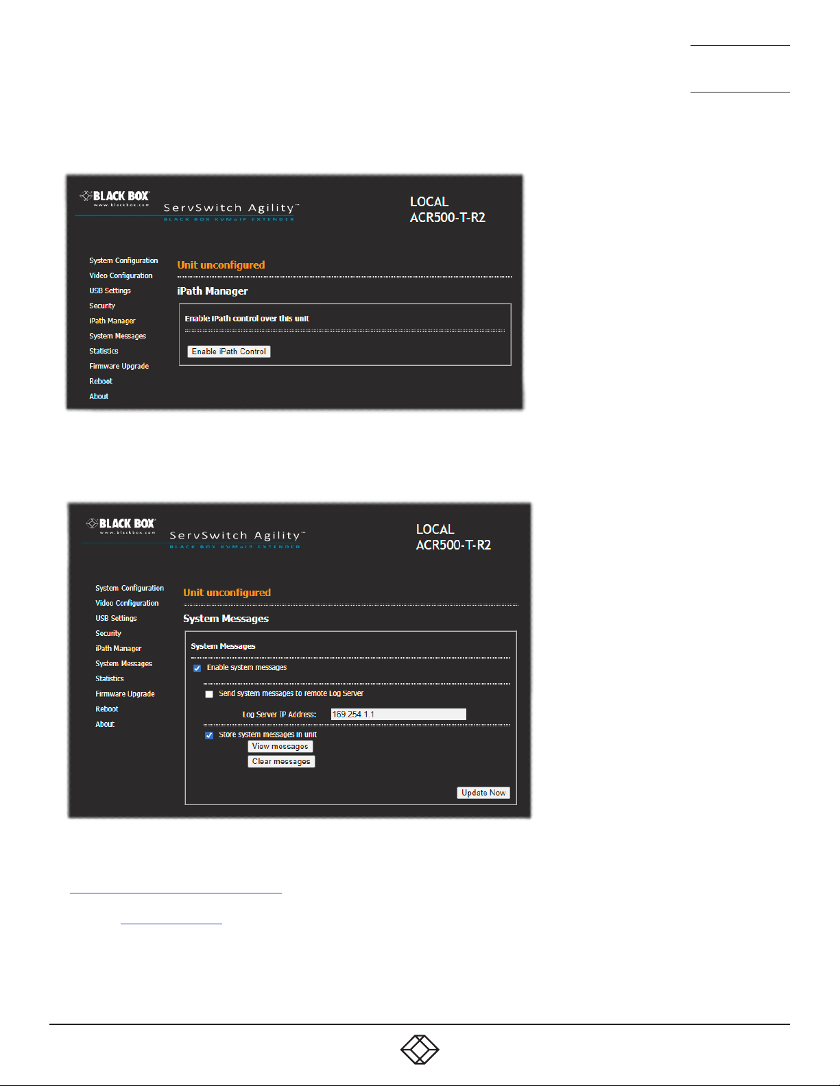
IPATH MANAGER
NEED HELP?
LEAVE T HE TECH TO U S
LIVE 24/7
TECHNICAL
SUPPORT
1.877.877.2269
Enable IPATH Control
Click this button to allow an iPATH Agility Controller to take control of this TX. When the button is
clicked, the Agility Zero U unit will be rebooted to
allow the IPATH box to discover and control it.
SYSTEM MESSAGES
To get here
1 Connect your computer to the network port on the front panel.
2 Run a web browser and enter the IP address of the unit. If the address is unknown,
perform a manual factory reset to http://169.254.1.33
3 Click either the IPATH Controller or System Messages links, as appropriate.
Enable system messages
Tick to allow the creation of status and error messages by Agility Zero U unit.
Send system messages to remote Log Server
Choose this option to send the system messages
to a remote server via the network. Provide the IP
address of a suitable server here also.
Note: iPATHAgilityControllers use the User Data-
gramProtocol(UDP)forallSyslogtrafc.
Store system messages in unit
When ticked, this option will store system messages within the memory of Agility Zero U unit.
Click the View messages button to view the list or
the Clearmessages button to delete the list.
Update Now
Click to save and implement any changes that you
make.
26
1. 87 7. 877. 2 269 BLACKBOX.COM
Page 27
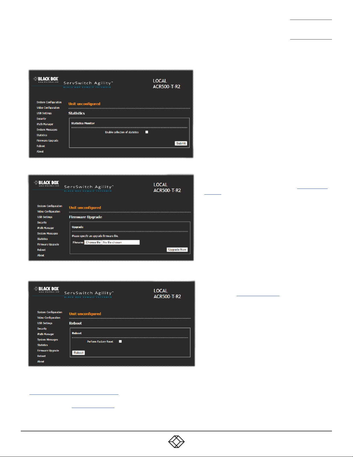
STATISTICS
FIRMWARE UPGRADE
NEED HELP?
LEAVE T HE TECH TO U S
LIVE 24/7
TECHNICAL
SUPPORT
1.877.877.2269
Enable collection of bandwidth statistics
Agility units can record data transfer statistics from the System port and plot them on a graph for troubleshooting and
optimization purposes. When you enable this option, you will
rst be presented with a pop up from which you can choose
which aspects you would like to graph: Data throughput, various packet rates and/or frame rates.
Submit
Click this button after ticking the above checkbox to plot the
chosen statistics on a pop up graph.
Upgrade
Use this page to upgrade the main or backup rmware image
on Agility Zero U unit. Please see the section Performing an
upgrade for details.
REBOOT
To get here
1 Connect your computer to the network port on the front panel.
2 Run a web browser and enter the IP address of the unit. If the address is
unknown, perform a manual factory reset to http://169.254.1.33
3 Click either the Statistics , Firmware Upgrade or Reboot links, as appropriate.
1. 87 7. 877. 2 269 BLACKBOX.COM
Reboot
Use this page to perform a reboot or a factory reset. Please
see the section Manual factory reset for details.
27
Page 28
ABOUT
NEED HELP?
LEAVE T HE TECH TO U S
LIVE 24/7
TECHNICAL
SUPPORT
1.877.877.2269
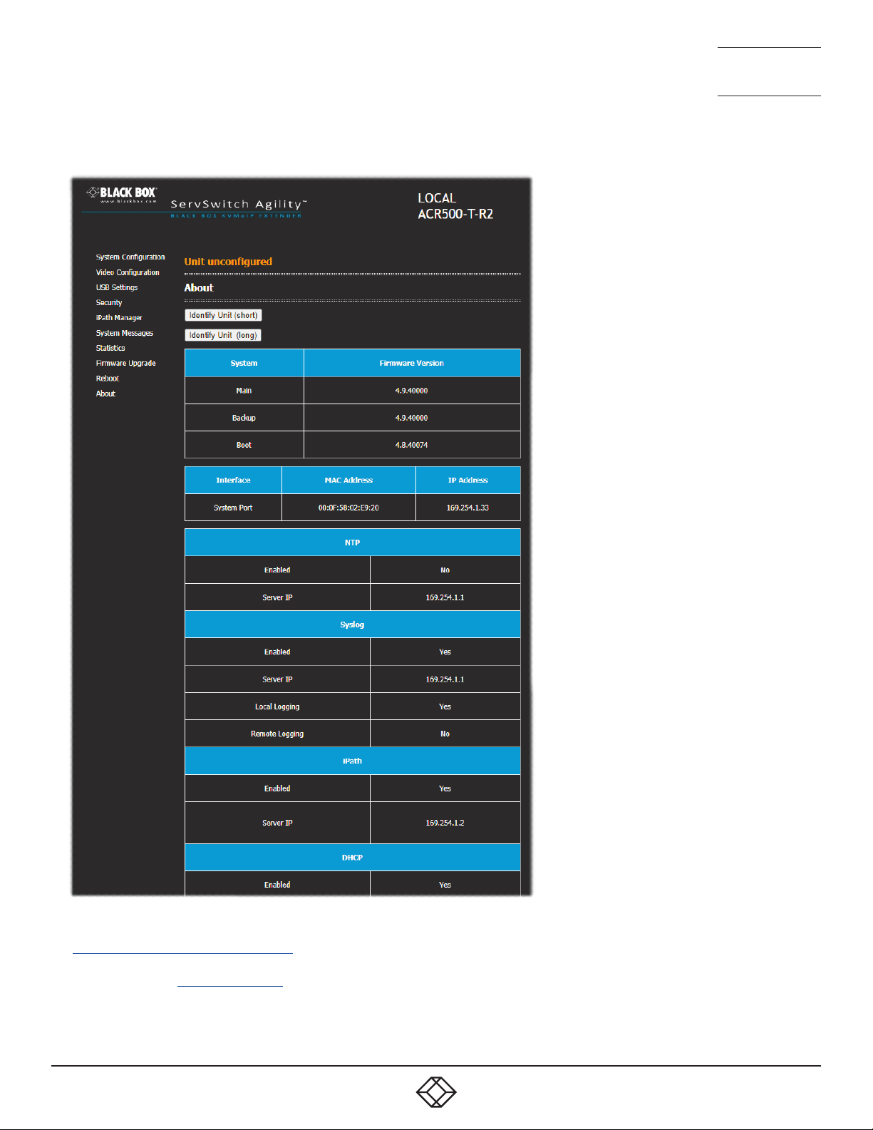
About
This page displays key information about the Agility Zero U unit that may be requested by Technical
Support.
To get here
1 Connect your computer to the network port on the front panel.
2 Run a web browser and enter the IP address of the unit. If the address is
unknown, perform a manual factory reset to http://169.254.1.33
3 Click the About link.
28
1. 87 7. 877. 2 269 BLACKBOX.COM
Page 29
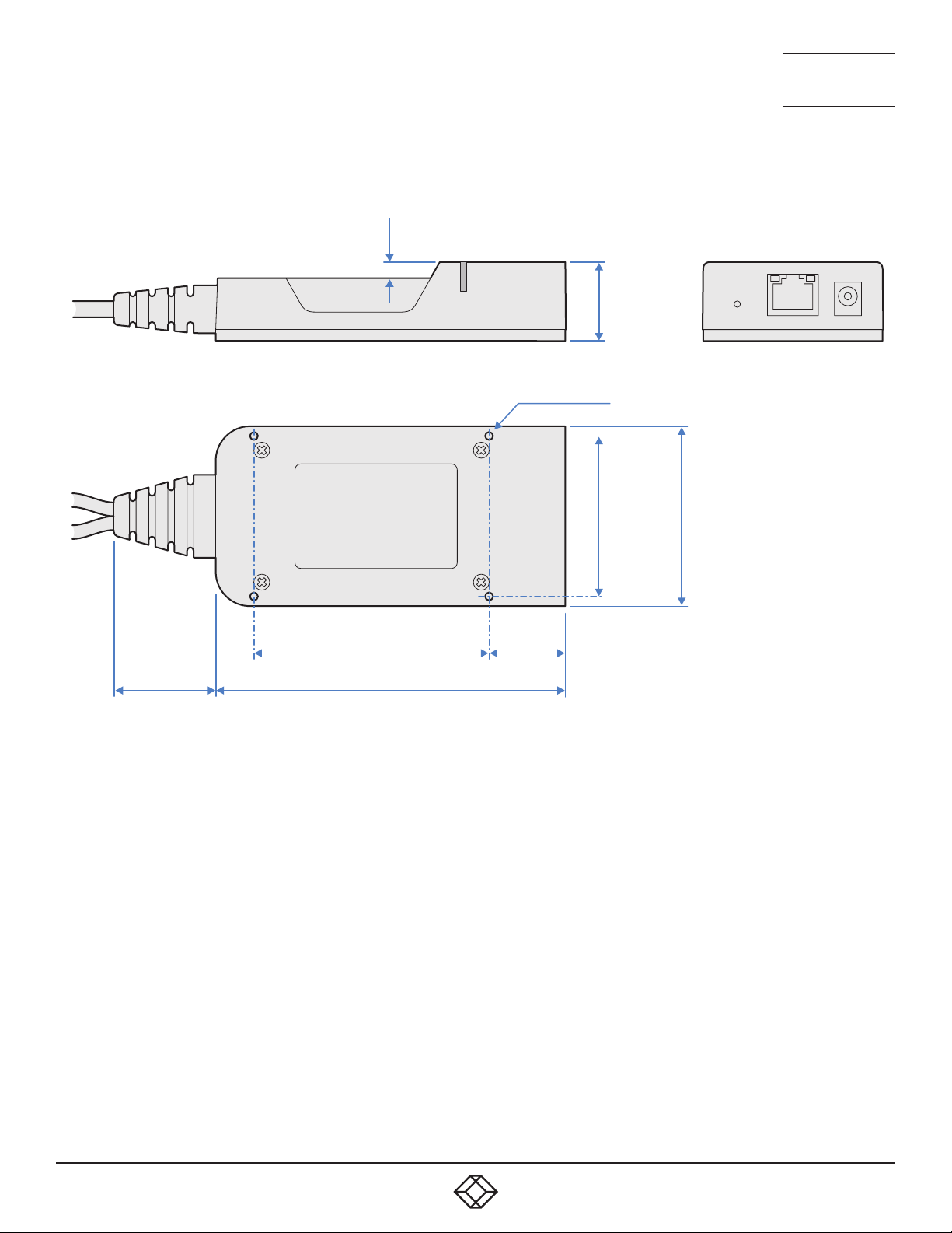
APPENDIX C - Dimensions
0.2”
(5mm)
4 x M3 holes
0.98”
(25mm)
NEED HELP?
LEAVE T HE TECH TO U S
LIVE 24/7
TECHNICAL
SUPPORT
1.877.877.2269
1.3”
(33mm)
2.95” (75mm)
4.33”(110mm)
0.91”
(23mm)
1.97”
(50mm)
2.2”
(56mm)
1. 87 7. 877. 2 269 BLACKBOX.COM
29
Page 30

NEED HELP?
LEAVE T HE TECH TO U S
LIVE 24/7
TECHNICAL
SUPPORT
1.877.877.2269
APPENDIX D - Tips for success when networking Agility units
Agility units use multiple strategies to minimize the amount of data that they send across networks. However, data overheads
can be quite high, particularly when very high resolution video is being transferred, so it is important to take steps to maximize
network efficiency and help minimize data output. The tips given in this section have been proven to produce very beneficial
results.
SUMMARY OF STEPS
• Choose the right kind of switch.
• Create an efficient network layout.
• Configure the switches and devices correctly.
CHOOSING THE RIGHT SWITCH
Layer 2 switches are what bind all of the hosts together in the subnet. However, they are all not created equally, so choose
carefully. In particular look for the following:
• Gigabit (1000Mbps) or faster Ethernet ports,
• Support for IGMP v2 (or v3) snooping,
• Support for Jumbo frames up to 9216-byte size,
• High bandwidth connections between switches, preferably Fiber Channel.
• Look for switches that perform their most onerous tasks (e.g. IGMP snooping) using multiple dedicated processors (ASICS).
• Ensure the maximum number of concurrent ‘snoopable groups’ the switch can handle meets or exceeds the number of Agility
transmitters that will be used to create multicast groups.
• Check the throughput of the switch: Full duplex, 1Gbps up- and down- stream speeds per port.
• Use the same switch make and model throughout a single subnet.
• You also need a Layer 3 switch. Ensure that it can operate efficiently as an IGMP Querier.
CREATING AN EFFICIENT NETWORK LAYOUT
Network layout is vital. The use of IGMP snooping also introduces certain constraints, so take heed:
• Keep it flat. Use a basic line-cascade structure rather than a pyramid or tree arrangement.
• Keep the distances between the switches as short as possible.
• Ensure sufficient bandwidth between switches to eliminate bottlenecks.
• Where the IPATH Agility Controller is used to administer multiple Agility transceivers, ensure the IPATH Agility Controller and all
Agility units reside in the same subnet.
• Do not use VGA converters, instead replace VGA video cards in older systems with suitable DisplayPort or HDMI replacements.
Converters cause Agility TX units to massively increase data output.
• Wherever possible, create a private network.
30
1. 87 7. 877. 2 269 BLACKBOX.COM
Page 31
NEED HELP?
LEAVE T HE TECH TO U S
LIVE 24/7
TECHNICAL
SUPPORT
1.877.877.2269
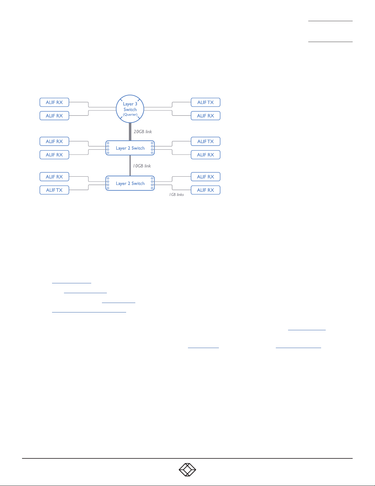
THE RECOMMENDED LAYOUT
The layout shown below has been found to provide the most efficient network layout for rapid throughput when using IGMP
snooping:
Note: From firmware version 3.1, tree and hierarchical structures of network switches are also supported. The Transmitter now
joins its own multicast group so there is always a route from the querier to the transmitter which was previously missing in
earlier firmware versions.
• Use no more than two cascade levels.
• Ensure high bandwidth between the two L2 switches and very high bandwidth between the top L2 and the L3. Typically 10GB
and 20GB, respectively for 48 port L2 switches.
CONFIGURING THE SWITCHES AND DEVICES
The layout is vital but so too is the configuration:
• Enable IGMP Snooping on all L2 switches.
• Ensure that IGMP Fast-Leave is enabled on all switches with Agility units connected directly to them.
• Enable the L3 switch as an IGMP Querier.
• Enable Spanning Tree Protocol (STP) on all switches and importantly also enable portfast (only) on all switch ports that have
Agility units connected.
• If any hosts will use any video resolutions using 2048 horizontal pixels (e.g. 2048 x 1152), ensure that Jumbo Frames are
enabled on all switches.
• Choose an appropriate forwarding mode on all switches. Use Cut-through if available, otherwise Store and forward.
• Optimize the settings on the Agility transmitters:
• If moving video images are being shown frequently, then leave Frame Skipping at a low percentage and instead reduce the
Peak bandwidth limiter.
• Where screens are quite static, try increasing the Background Refresh interval and/or increasing the Frame skipping
percentage setting.
Make changes to the Agility transmitters one at a time, in small steps, and view typical video images so that you can attribute
positive or negative results to the appropriate control.
• Ensure that all Agility units are fully updated to the latest firmware version (at least v2.1).
1. 87 7. 877. 2 269 BLACKBOX.COM
31
Page 32

NEED HELP?
LEAVE T HE TECH TO U S
LIVE 24/7
TECHNICAL
SUPPORT
1.877.877.2269
APPENDIX E - Troubleshooting
PROBLEM: THE VIDEO IMAGE OF THE AGILITY RECEIVER SHOWS HORIZONTAL LINES ACROSS THE SCREEN.
This issue is known as Blinding because the resulting video image looks as though you’re viewing it through a venetian blind.
When video is transmitted by Agility units, the various lines of each screen are divided up and transmitted as separate data
packets. If the reception of those packets is disturbed, then blinding is caused. The lines are displayed in place of the missing
video data packets.
There are several possible causes for the loss of data packets:
• Incorrect switch configuration. The problem could be caused by multicast flooding, which causes unnecessary network traffic.
This is what IGMP snooping is designed to combat, however, there can be numerous causes of the flooding.
• Speed/memory bandwidth issues within one or more switches. The speed and capabilities of different switch models varies
greatly. If a switch cannot maintain pace with the quantity of data being sent through it, then it will inevitably start dropping
packets.
• One or more Agility units may be outputting Jumbo frames due to the video resolution (2048 horizontal pixels) being used.
If jumbo frames are output by an Agility unit, but the network switches have not been configured to use jumbo frames, the
switches will attempt to break the large packets down into standard packets. This process introduces a certain latency and
could be a cause for dropped packets.
• One or more Agility units may be using an old firmware version. Firmware versions prior to v2.1 exhibited an issue with the
timing of IGMP join and leave commands that caused multicast flooding in certain configurations.
REMEDIES:
• Ensure that IGMP snooping is enabled on all switches within the subnet.
• Where each Agility unit is connected as the sole device on a port connection to a switch, enable IGMP Fast-Leave (aka
Immediate Leave) to reduce unnecessary processing on each switch.
• Check the video resolution(s) being fed into the Agility transmitters. If resolutions using 2048 horizontal pixels are unavoidable
then ensure that Jumbo frames are enabled on all switches.
• Check the forwarding mode on the switches. If Store and forward is being used, try selecting Cut-through as this mode causes
reduced latency on lesser switch designs.
• Ensure that one device within the subnet is correctly configured as an IGMP Querier, usually a layer 3 switch or multicast
router.
• Ensure that the firmware in every Agility unit is version 2.1 or greater.
• Try adjusting the transmitter settings on each Agility to make the output data stream as efficient as possible.
32
1. 87 7. 877. 2 269 BLACKBOX.COM
Page 33

NEED HELP?
LEAVE T HE TECH TO U S
LIVE 24/7
TECHNICAL
SUPPORT
1.877.877.2269
PROBLEM: THE MOUSE POINTER OF THE AGILITY RECEIVER IS SLOW OR SLUGGISH WHEN MOVED ACROSS THE
SCREEN.
This issue is often related to either using dithering on the video output of one or more transmitting computers or using video
converters.
Dithering is used to improve the perceived quality and color depth of images by diffusing or altering the color of pixels between
video frames. This practice is commonly used on Apple Mac computers using ATI or Nvidia graphics cards. VGA converters
unwittingly produce a similar issue by creating high levels of pixel background noise.
Agility units attempt to considerably reduce network traffic by transmitting only the pixels that change between successive
video frames. When dithering is enabled and/or VGA converters are used, this can have the effect of changing almost every pixel
between each frame, thus forcing the Agility transmitter to send the whole of every frame: resulting in greatly increased network
traffic and what’s perceived as sluggish performance.
REMEDIES:
• Linux PCs
Check the video settings on the PC. If the Dither video box option is enabled, disable it.
• Apple Mac with ATI graphics
Enable the Magic Eye dither removal feature.
• Windows PCs
If you suspect these issues with PC’s, contact technical support for assistance.
• Replace old VGA adapters on host computers with DisplayPort or HDMI video cards.
PROBLEM: THE AUDIO OUTPUT OF THE AGILITY RECEIVER SOUNDS LIKE A SCRATCHED RECORD.
This issue is called Audio crackle and is a symptom of the same problem that produces blinding (see previous page). The issue is
related to missing data packets.
REMEDIES:
As per blinding discussed previously.
PROBLEM: IPATH CANNOT LOCATE WORKING AGILITY UNITS.
There are a few possible causes:
• The Agility units must be reset back to their zero config IP addresses for IPATH discovery. If you have a working network of
Agility’s without IPATH and then add IPATH to the network IPATH will not discover the Agility units until they are reset to the
zero config IP addresses.
• This could be caused by Layer 2 Cisco switches that have Spanning Tree Protocol (STP) enabled but do not also have portfast
enabled on the ports to which Agility units are connected. Without portfast enabled, Agility units will all be assigned the same
zero config IP address at reboot and IPATH will only acquire them one at a time on a random basis.
You can easily tell whether portfast is enabled on a switch that is running STP: When you plug the link cable from a working
Agility unit into the switch port, check how long it takes for the port indicator to change from orange to green. If it takes roughly
one second, portfast is on; if it takes roughly thirty seconds then portfast is disabled.
REMEDIES:
• Ensure that the Agility units and the IPATH Agility Controller are located within the same subnet because iPATH cannot cross
subnet boundaries.
• Manually reset the Agility units to their zero config IP addresses.
• Enable portfast on all switch ports that have Agility units attached to them or try temporarily disabling STP on the switches
while IPATH is attempting to locate Agility units.
1. 87 7. 877. 2 269 BLACKBOX.COM
33
Page 34

NEED HELP?
LEAVE T HE TECH TO U S
LIVE 24/7
TECHNICAL
SUPPORT
1.877.877.2269
APPENDIX F - Glossary
INTERNET GROUP MANAGEMENT PROTOCOL
Where an Agility transmitter is required to stream video to two or more receivers, multicasting is the method used.
Multicasting involves the delivery of identical data to multiple receivers simultaneously without the need to maintain individual links.
When multicast data packets enter a subnet, the natural reaction of the switches that bind all the hosts together within the subnet,
is to spread the multicast data to all of their ports. This is referred to as Multicast flooding and means that the hosts (or at least their
network interfaces) are required to process plenty of data that they didn’t request. IGMP offers a partial solution.
The Internet Group Management Protocol (IGMP) is designed to prevent multicast flooding by allowing Layer 3 switches to
check whether host computers within their care are interested in receiving particular multicast transmissions. They can then direct
multicast data only to those points that require it and can shut off a multicast stream if the subnet has no recipients.
There are currently three IGMP versions: 1, 2 and 3, with each version building upon the capabilities of the previous one:
• IGMPv1 allows host computers to opt into a multicast transmission using a Join Group message, it is then incumbent on the
router to discover when they no longer wish to receive; this is achieved by polling them (see IGMP Querier below) until they no
longer respond.
• IGMPv2 includes the means for hosts to opt out as well as in, using a Leave Group message.
• IGMPv3 encompasses the abilities of versions 1 and 2 but also adds the ability for hosts to specify particular sources of
multicast data.
Agility units make use of IGMPv2 when performing multicasts to ensure that no unnecessary congestion is caused.
IGMP SNOOPING
The IGMP messages are effective but only operate at layer 2 - intended for routers to determine whether multicast data should
enter a subnet. A relatively recent development has taken place within the switches that glue together all of the hosts within each
subnet: IGMP Snooping. IGMP snooping means these layer 2 devices now have the ability to take a peek at the IGMP messages.
As a result, the switches can then determine exactly which of their own hosts have requested to receive a multicast – and only
pass on multicast data to those hosts.
IGMP QUERIER
When IGMP is used, each subnet requires one Layer 3 switch to act as a Querier. In this lead role, the switch periodically sends
out IGMP Query messages and in response all hosts report which multicast streams they wish to receive. The Querier device and
all snooping Layer 2 switches, then update their lists accordingly (the lists are also updated when Join Group and Leave Group
(IGMPv2) messages are received).
IGMP FAST-LEAVE (AKA IMMEDIATE LEAVE)
When a device/host no longer wishes to receive a multicast transmission, it can issue an IGMP Leave Group message as
mentioned above. This causes the switch to issue an IGMP Group-Specific Query message on the port (that the Leave Group was
received on) to check no other receivers exist on that connection that wish to remain a part of the multicast. This process has a
cost in terms of switch processor activity and time.
Where Agility units are connected directly to the switch (with no other devices on the same port) then enabling IGMP Fast-Leave
mode means that switches can immediately remove receivers without going through a full checking procedure. Where multiple
units are regularly joining and leaving multicasts, this can speed up performance considerably.
34
1. 87 7. 877. 2 269 BLACKBOX.COM
Page 35

NEED HELP?
LEAVE T HE TECH TO U S
LIVE 24/7
TECHNICAL
SUPPORT
1.877.877.2269
JUMBO FRAMES (JUMBO PACKETS)
Since its commercial introduction in 1980, the Ethernet standard has been successfully extended and adapted to keep pace with
the ever improving capabilities of computer systems. The achievable data rates, for instance, have risen in ten-fold leaps from the
original 10Mbit/s to a current maximum of 100Gbit/s.
While data speeds have increased massively, the standard defining the number of bytes (known as the Payload) placed into each
data packet has remained resolutely stuck at its original level of 1500 bytes. This standard was set during the original speed era
(10Mbits/s) and offered the best compromise at that speed between the time taken to process each packet and the time required
to resend faulty packets due to transmission errors.
But now networks are much faster and files/data streams are much larger; so time for a change? Unfortunately, a wholesale
change to the packet size is not straightforward as it is a fundamental standard and changing it would mean a loss of backward
compatibility with older systems.
Larger payload options have been around for a while, however, they have often been vendor specific and at present they remain
outside the official standard. There is, however, increased consensus on an optional ‘Jumbo’ payload size of 9000 bytes and this
is fully supported by the Agility units.
Jumbo frames (or Jumbo packets) offer advantages for Agility units when transmitting certain high resolution video signals
across a network. This is because the increased data in each packet reduces the number of packets that need to be transferred
and dealt with - thus reducing latency times.
The main problem is that for jumbo frames to be possible on a network, all of the devices on the network must support them.
SPANNING TREE PROTOCOL (STP)
In order to build a robust network, it is necessary to include certain levels of redundancy within the interconnections between
switches. This will help to ensure that a failure of one link does not lead to a complete failure of the whole network.
The danger of multiple links is that data packets, especially multicast packets, become involved in continual loops as
neighbouring switches use the duplicated links to send and resend them to each other.
To prevent such bridging loops from occurring, the Spanning Tree Protocol (STP), operating at layer 2, is used within each
switch. STP encourages all switches to communicate and learn about each other. It prevents bridging loops by blocking newly
discovered links until it can discover the nature of the link: is it a new host or a new switch?
The problem with this is that the discovery process can take up to 50 seconds before the block is lifted, causing problematic
timeouts.
The answer to this issue is to enable the portfast variable for all host links on a switch. This will cause any new connection to go
immediately into forwarding mode. However, take particular care not to enable portfast on any switch to switch connections as
this will result in bridging loops.
1. 87 7. 877. 2 269 BLACKBOX.COM
35
Page 36

NEED HELP?
LEAVE T HE TECH TO U S
LIVE 24/7
TECHNICAL
SUPPORT
1.877.877.2269
FORWARDING MODES
In essence, the job of a layer 2 switch is to transfer as fast as possible, data packets arriving at one port out to another port as
determined by the destination address. This is known as data forwarding and most switches offer a choice of methods to achieve
this. Choosing the most appropriate forwarding method can often have a sizeable impact on the overall speed of switching:
• Store and forward is the original method and requires the switch to save each entire data packet to buffer memory, run an error
check and then forward if no error is found (or otherwise discard it).
• Cut-through was developed to address the latency issues suffered by some store and forward switches. The switch begins
interpreting each data packet as it arrives. Once the initial addressing information has been read, the switch immediately
begins forwarding the data packet while the remainder is still arriving. Once all of the packet has been received, an error check
is performed and, if necessary, the packet is tagged as being in error. This checking ‘on-the-fly’ means that cut-through
switches cannot discard faulty packets themselves. However, on receipt of the marked packet, a host will carry out the discard
process.
• Fragment-free is a hybrid of the above two methods. It waits until the first 64 bits have been received before beginning to
forward each data packet. This way the switch is more likely to locate and discard faulty packets that are fragmented due to
collisions with other data packets.
• Adaptive switches automatically choose between the above methods. Usually they start out as a cut-through switches and
change to store and forward or fragment-free methods if large number of errors or collisions are detected.
So which one to choose? The Cut-through method has the least latency so is usually the best to use with Agility units. However,
if the network components and/or cabling generate a lot of errors, the Store and forward method should probably be used. On
higher end store and forward switches, latency is rarely an issue.
LAYER 2 AND LAYER 3: THE OSI MODEL
When discussing network switches, the terms Layer 2 and Layer 3 are very often used. These refer to parts of the Open System
Interconnection (OSI) model, a standardized way to categorize the necessary functions of any standard network.
There are seven layers in the OSI model and these define the steps needed to get the data created by you (imagine that you are
Layer 8) reliably down onto the transmission medium (the cable, optical fiber, radio wave, etc.) that carries the data to another
user; to complete the picture, consider the transmission medium is Layer 0. In general, think of the functions carried out by the
layers at the top as being complex, becoming less complex as you go lower down.
As your data travel down from you towards the transmission medium
(the cable), they are successively encapsulated at each layer within a
new wrapper (along with a few instructions), ready for transport. Once
transmission has been made to the intended destination, the reverse
occurs: Each wrapper is stripped away and the instructions examined
until finally only the original data are left.
So why are Layer 2 and Layer 3 of particular importance when discussing
Agility? Because the successful transmission of data relies upon fast and
reliable passage through network switches – and most of these operate
at either Layer 2 or Layer 3.
The job of any network switch is to receive each incoming network packet, strip away only the first few wrappers to discover the
intended destination then rewrap the packet and send it in the correct direction.
In simplified terms, the wrapper that is added at Layer 2 (by the sending system) includes the physical address of the intended
recipient system, i.e. the unique MAC address (for example, 09:f8:33:d7:66:12) that is assigned to every networking device at
manufacture. Deciphering recipients at this level is more straightforward than at Layer 3, where the address of the recipient is
represented by a logical IP address (e.g. 192.168.0.10) and requires greater knowledge of the surrounding network structure. Due
to their more complex circuitry, Layer 3 switches are more expensive than Layer 2 switches of a similar build quality and are used
more sparingly within installations.
36
1. 87 7. 877. 2 269 BLACKBOX.COM
Page 37

NEED HELP?
LEAVE T HE TECH TO U S
LIVE 24/7
TECHNICAL
SUPPORT
1.877.877.2269
APPENDIX G - Open source licenses
This product includes binaries that are derived from the open source community. The modules listed below are licenced under
the GNU General Public License v2 and must be provided, in source form, on request:
dtc
u-boot-xlnx
linux-xlnx
busybox
util-linux
udev
termcap
mtd-utils
libpbe
haserl
The software included in this product contains copyrighted software that is licensed under the GPL. You may obtain the complete
Corresponding Source code from Black Box for a period of three years after the last shipment of this product, which will be no
earlier than 2028, by contacting the support department
This product includes binaries that are derived from the open source community. The modules listed below are licenced under
the GNU Lesser General Public License v2.1 and must be provided, in source form, on request:
kmod
libdaemon
avahi
libgpg-error
nettle
libgcrypt
gnutls
libmicrohttpd
In addition to the GPL modules listed, this product also includes binaries derived from 3rd party open sources that have their own
license requirements. Each module is listed below with their required Copyright statement and distribution conditions.
----------------------------------------------------------------------------
-
- Module: openssl
-
----------------------------------------------------------------------------
LICENSE ISSUES
==============
The OpenSSL toolkit stays under a dual license, i.e. both the conditions of
the OpenSSL License and the original SSLeay license apply to the toolkit.
See below for the actual license texts. Actually both licenses are BSD-style
Open Source licenses. In case of any license issues related to OpenSSL
please contact [email protected].
1. 87 7. 877. 2 269 BLACKBOX.COM
37
Page 38

NEED HELP?
LEAVE T HE TECH TO U S
LIVE 24/7
TECHNICAL
SUPPORT
1.877.877.2269
OpenSSL License
---------------
/* ====================================================================
Copyright (c) 1998-2011 The OpenSSL Project. All rights reserved.
Redistribution and use in source and binary forms, with or without modification, are permitted provided that the following
conditions are met:
1. Redistributions of source code must retain the above copyright notice, this list of conditions and the following disclaimer.
2. Redistributions in binary form must reproduce the above copyright notice, this list of conditions and the following disclaimer in
the documentation and/or other materials provided with the distribution.
3. All advertising materials mentioning features or use of this software must display the following acknowledgment: “This product
includes software developed by the OpenSSL Project for use in the OpenSSL Toolkit. (http://www.openssl.org/)”
4. The names “OpenSSL Toolkit” and “OpenSSL Project” must not be used to endorse or promote products derived from this
software without prior written permission. For written permission, please contact [email protected].
5. Products derived from this software may not be called “OpenSSL” nor may “OpenSSL” appear in their names without prior written
permission of the OpenSSL Project.
6. Redistributions of any form whatsoever must retain the following acknowledgment:
“This product includes software developed by the OpenSSL Project for use in the OpenSSL Toolkit (http://www.openssl.org/)”
THIS SOFTWARE IS PROVIDED BY THE OpenSSL PROJECT ``AS IS’’ AND ANY
EXPRESSED OR IMPLIED WARRANTIES, INCLUDING, BUT NOT LIMITED TO, THE
IMPLIED WARRANTIES OF MERCHANTABILITY AND FITNESS FOR A PARTICULAR
PURPOSE ARE DISCLAIMED. IN NO EVENT SHALL THE OpenSSL PROJECT OR
ITS CONTRIBUTORS BE LIABLE FOR ANY DIRECT, INDIRECT, INCIDENTAL,
SPECIAL, EXEMPLARY, OR CONSEQUENTIAL DAMAGES (INCLUDING, BUT
NOT LIMITED TO, PROCUREMENT OF SUBSTITUTE GOODS OR SERVICES;
LOSS OF USE, DATA, OR PROFITS; OR BUSINESS INTERRUPTION)
HOWEVER CAUSED AND ON ANY THEORY OF LIABILITY, WHETHER IN CONTRACT, STRICT LIABILITY, OR TORT (INCLUDING
NEGLIGENCE OR OTHERWISE) ARISING IN ANY WAY OUT OF THE USE OF THIS SOFTWARE, EVEN IF ADVISED OF THE POSSIBILITY
OF SUCH DAMAGE.
=============================================================
This product includes cryptographic software written by Eric Young ([email protected]). This product includes software written
by Tim Hudson ([email protected]).
*/
Original SSLeay License
-----------------------
/* Copyright (C) 1995-1998 Eric Young ([email protected]) All rights reserved.
*
This package is an SSL implementation written by Eric Young ([email protected]).
38
1. 87 7. 877. 2 269 BLACKBOX.COM
Page 39

NEED HELP?
LEAVE T HE TECH TO U S
LIVE 24/7
TECHNICAL
SUPPORT
1.877.877.2269
The implementation was written so as to conform with Netscapes SSL.
*
This library is free for commercial and non-commercial use as long as the following conditions are aheared to. The following
conditions apply to all code found in this distribution, be it the RC4, RSA, lhash, DES, etc., code; not just the SSL code. The SSL
documentation included with this distribution is covered by the same copyright terms
except that the holder is Tim Hudson ([email protected]).
*
Copyright remains Eric Young’s, and as such any Copyright notices in the code are not to be removed. If this package is used in a
product, Eric Young should be given attribution
as the author of the parts of the library used. This can be in the form of a textual message at program startup or in documentation
(online or textual) provided with the package.
*
Redistribution and use in source and binary forms, with or without modification, are permitted provided that the following
conditions are met:
1. Redistributions of source code must retain the copyright
notice, this list of conditions and the following disclaimer.
2. Redistributions in binary form must reproduce the above copyright
notice, this list of conditions and the following disclaimer in the
documentation and/or other materials provided with the distribution.
3. All advertising materials mentioning features or use of this software
must display the following acknowledgement:
“This product includes cryptographic software written by
Eric Young ([email protected])”
The word ‘cryptographic’ can be left out if the rouines from the library
being used are not cryptographic related :-).
4. If you include any Windows specific code (or a derivative thereof) from
the apps directory (application code) you must include an acknowledgement:
“This product includes software written by Tim Hudson ([email protected])”
*
THIS SOFTWARE IS PROVIDED BY ERIC YOUNG ``AS IS’’ AND
ANY EXPRESS OR IMPLIED WARRANTIES, INCLUDING, BUT NOT LIMITED TO, THE
IMPLIED WARRANTIES OF MERCHANTABILITY AND FITNESS FOR A PARTICULAR PURPOSE ARE DISCLAIMED. IN NO EVENT
SHALL THE AUTHOR OR CONTRIBUTORS BE LIABLE FOR ANY DIRECT, INDIRECT, INCIDENTAL, SPECIAL, EXEMPLARY, OR
CONSEQUENTIAL DAMAGES (INCLUDING, BUT NOT LIMITED TO, PROCUREMENT OF SUBSTITUTE GOODS OR SERVICES; LOSS
OF USE, DATA, OR PROFITS; OR BUSINESS INTERRUPTION) HOWEVER CAUSED AND ON ANY THEORY OF LIABILITY, WHETHER IN
CONTRACT, STRICT LIABILITY, OR TORT (INCLUDING NEGLIGENCE OR OTHERWISE) ARISING IN ANY WAY OUT OF THE USE OF THIS
SOFTWARE, EVEN IF ADVISED OF THE POSSIBILITY OF SUCH DAMAGE.
*
The licence and distribution terms for any publically available version or derivative of this code cannot be changed. i.e. this code
cannot simply be copied and put under another distribution licence [including the GNU Public Licence.]
*/
----------------------------------------------------------------------------
-
- Module: libev
-
----------------------------------------------------------------------------
All files in libev are
1. 87 7. 877. 2 269 BLACKBOX.COM
39
Page 40

NEED HELP?
LEAVE T HE TECH TO U S
LIVE 24/7
TECHNICAL
SUPPORT
1.877.877.2269
Copyright (c)2007,2008,2009,2010,2011,2012,2013 Marc Alexander Lehmann.
Redistribution and use in source and binary forms, with or without
modification, are permitted provided that the following conditions are
met:
* Redistributions of source code must retain the above copyright
notice, this list of conditions and the following disclaimer.
* Redistributions in binary form must reproduce the above
copyright notice, this list of conditions and the following
disclaimer in the documentation and/or other materials provided
with the distribution.
THIS SOFTWARE IS PROVIDED BY THE COPYRIGHT HOLDERS AND CONTRIBUTORS “AS IS” AND ANY EXPRESS OR IMPLIED
WARRANTIES, INCLUDING, BUT NOT LIMITED TO, THE IMPLIED WARRANTIES OF MERCHANTABILITY AND FITNESS FOR A
PARTICULAR PURPOSE ARE DISCLAIMED. IN NO EVENT SHALL THE COPYRIGHT OWNER OR CONTRIBUTORS BE LIABLE FOR
ANY DIRECT, INDIRECT, INCIDENTAL, SPECIAL, EXEMPLARY, OR CONSEQUENTIAL DAMAGES (INCLUDING, BUT NOT LIMITED
TO, PROCUREMENT OF SUBSTITUTE GOODS OR SERVICES; LOSS OF USE, DATA, OR PROFITS; OR BUSINESS INTERRUPTION)
HOWEVER CAUSED AND ON ANY
THEORY OF LIABILITY, WHETHER IN CONTRACT, STRICT LIABILITY, OR TORT
(INCLUDING NEGLIGENCE OR OTHERWISE) ARISING IN ANY WAY OUT OF THE USE OF THIS SOFTWARE, EVEN IF ADVISED OF THE
POSSIBILITY OF SUCH DAMAGE.
----------------------------------------------------------------------------
-
- Module: libaes
-
----------------------------------------------------------------------------
Copyright (c) 1998-2008, Brian Gladman, Worcester, UK. All rights reserved.
LICENSE TERMS
The redistribution and use of this software (with or without changes)
is allowed without the payment of fees or royalties provided that:
1. source code distributions include the above copyright notice, this
list of conditions and the following disclaimer;
2. binary distributions include the above copyright notice, this list
of conditions and the following disclaimer in their documentation;
3. the name of the copyright holder is not used to endorse products
built using this software without specific written permission.
DISCLAIMER
This software is provided ‘as is’ with no explicit or implied warranties
40
1. 87 7. 877. 2 269 BLACKBOX.COM
Page 41

in respect of its properties, including, but not limited to, correctness
and/or fitness for purpose.
----------------------------------------------------------------------------
-
- Module: libgcrypt
-
----------------------------------------------------------------------------
Additional license notices for Libgcrypt. -*- org -*-
This file contains the copying permission notices for various files in
the Libgcrypt distribution which are not covered by the GNU Lesser
General Public License (LGPL) or the GNU General Public License (GPL).
These notices all require that a copy of the notice be included
in the accompanying documentation and be distributed with binary
distributions of the code, so be sure to include this file along
with any binary distributions derived from the GNU C Library.
* BSD_3Clause
For files:
- cipher/sha256-avx-amd64.S
- cipher/sha256-avx2-bmi2-amd64.S
- cipher/sha256-ssse3-amd64.S
- cipher/sha512-avx-amd64.S
- cipher/sha512-avx2-bmi2-amd64.S
- cipher/sha512-ssse3-amd64.S
#+begin_quote
Copyright (c) 2012, Intel Corporation
All rights reserved.
Redistribution and use in source and binary forms, with or without
modification, are permitted provided that the following conditions are
met:
* Redistributions of source code must retain the above copyright
notice, this list of conditions and the following disclaimer.
* Redistributions in binary form must reproduce the above copyright
notice, this list of conditions and the following disclaimer in the
documentation and/or other materials provided with the
distribution.
* Neither the name of the Intel Corporation nor the names of its
NEED HELP?
LEAVE T HE TECH TO U S
LIVE 24/7
TECHNICAL
SUPPORT
1.877.877.2269
1. 87 7. 877. 2 269 BLACKBOX.COM
41
Page 42

NEED HELP?
LEAVE T HE TECH TO U S
LIVE 24/7
TECHNICAL
SUPPORT
1.877.877.2269
contributors may be used to endorse or promote products derived from
this software without specific prior written permission.
THIS SOFTWARE IS PROVIDED BY INTEL CORPORATION “AS IS” AND ANY
EXPRESS OR IMPLIED WARRANTIES, INCLUDING, BUT NOT LIMITED TO, THE
IMPLIED WARRANTIES OF MERCHANTABILITY AND FITNESS FOR A PARTICULAR
PURPOSE ARE DISCLAIMED. IN NO EVENT SHALL INTEL CORPORATION OR
CONTRIBUTORS BE LIABLE FOR ANY DIRECT, INDIRECT, INCIDENTAL, SPECIAL,
EXEMPLARY, OR CONSEQUENTIAL DAMAGES (INCLUDING, BUT NOT LIMITED TO, PROCUREMENT OF SUBSTITUTE GOODS
OR SERVICES; LOSS OF USE, DATA, OR PROFITS; OR BUSINESS INTERRUPTION) HOWEVER CAUSED AND ON ANY THEORY OF
LIABILITY, WHETHER IN CONTRACT, STRICT LIABILITY, OR TORT (INCLUDING NEGLIGENCE OR OTHERWISE) ARISING IN ANY WAY
OUT OF THE USE OF THIS SOFTWARE, EVEN IF ADVISED OF THE POSSIBILITY OF SUCH DAMAGE.
#+end_quote
* X License
For files:
- install.sh
#+begin_quote
Copyright (C) 1994 X Consortium
Permission is hereby granted, free of charge, to any person obtaining a copy
of this software and associated documentation files (the “Software”), to
deal in the Software without restriction, including without limitation the
rights to use, copy, modify, merge, publish, distribute, sublicense, and/or
sell copies of the Software, and to permit persons to whom the Software is
furnished to do so, subject to the following conditions:
The above copyright notice and this permission notice shall be included in
all copies or substantial portions of the Software.
THE SOFTWARE IS PROVIDED “AS IS”, WITHOUT WARRANTY OF ANY KIND, EXPRESS OR IMPLIED, INCLUDING BUT NOT LIMITED
TO THE WARRANTIES OF MERCHANTABILITY, FITNESS FOR A PARTICULAR PURPOSE AND NONINFRINGEMENT. IN NO EVENT
SHALL THE X CONSORTIUM BE LIABLE FOR ANY CLAIM, DAMAGES OR OTHER LIABILITY, WHETHER IN AN ACTION OF CONTRACT,
TORT OR OTHERWISE, ARISING FROM, OUT OF OR IN CONNECTION WITH THE SOFTWARE OR THE USE OR OTHER DEALINGS IN
THE SOF TWARE.
Except as contained in this notice, the name of the X Consortium shall not
be used in advertising or otherwise to promote the sale, use or other deal ings in this Software without prior written authorization from the X Consor-
tium.
#+end_quote
* Public domain
For files:
42
1. 87 7. 877. 2 269 BLACKBOX.COM
Page 43

- cipher/arcfour-amd64.S
#+begin_quote
Author: Marc Bevand <bevand_m (at) epita.fr>
Licence: I hereby disclaim the copyright on this code and place it
in the public domain.
#+end_quote
* OCB license 1
For files:
- cipher/cipher-ocb.c
#+begin_quote
OCB is covered by several patents but may be used freely by most
software. See http://web.cs.ucdavis.edu/~rogaway/ocb/license.htm .
In particular license 1 is suitable for Libgcrypt: See
http://web.cs.ucdavis.edu/~rogaway/ocb/license1.pdf for the full
license document; it basically says:
License 1 — License for Open-Source Software Implementations of OCB
(Jan 9, 2013)
Under this license, you are authorized to make, use, and
distribute open-source software implementations of OCB. This
license terminates for you if you sue someone over their
open-source software implementation of OCB claiming that you have
a patent covering their implementation.
License for Open Source Software Implementations of OCB
January 9, 2013
1 Definitions
1.1 “Licensor” means Phillip Rogaway.
1.2 “Licensed Patents” means any patent that claims priority to United
States Patent Application No. 09/918,615 entitled “Method and Apparatus
for Facilitating Efficient Authenticated Encryption,” and any utility,
divisional, provisional, continuation, continuations-in-part, reexamination,
reissue, or foreign counterpart patents that may issue with respect to the
aforesaid patent application. This includes, but is not limited to, United
States Patent No. 7,046,802; United States Patent No. 7,200,227; United
States Patent No. 7,949,129; United States Patent No. 8,321,675 ; and any
patent that issues out of United States Patent Application No. 13/669,114.
1.3 “Use” means any practice of any invention claimed in the Licensed Patents.
NEED HELP?
LEAVE T HE TECH TO U S
LIVE 24/7
TECHNICAL
SUPPORT
1.877.877.2269
1. 87 7. 877. 2 269 BLACKBOX.COM
43
Page 44

NEED HELP?
LEAVE T HE TECH TO U S
LIVE 24/7
TECHNICAL
SUPPORT
1.877.877.2269
1.4 “Software Implementation” means any practice of any invention
claimed in the Licensed Patents that takes the form of software executing on
a user-programmable, general-purpose computer or that takes the form of a
computer-readable medium storing such software. Software Implementation does
not include, for example, application-specific integrated circuits (ASICs),
field-programmable gate arrays (FPGAs), embedded systems, or IP cores.
1.5 “Open Source Software” means software whose source code is published
and made available for inspection and use by anyone because either (a) the
source code is subject to a license that permits recipients to copy, modify,
and distribute the source code without payment of fees or royalties, or
(b) the source code is in the public domain, including code released for
public use through a CC0 waiver. All licenses certified by the Open Source
Initiative at opensource.org as of January 9, 2013 and all Creative Commons
licenses identified on the creativecommons.org website as of January 9,
2013, including the Public License Fallback of the CC0 waiver, satisfy these
requirements for the purposes of this license.
1.6 “Open Source Software Implementation” means a Software
Implementation in which the software implicating the Licensed Patents is
Open Source Software. Open Source Software Implementation does not include
any Software Implementation in which the software implicating the Licensed
Patents is combined, so as to form a larger program, with software that is
not Open Source Software.
2 License Grant
2.1 License. Subject to your compliance with the term s of this license,
including the restriction set forth in Section 2.2, Licensor hereby
grants to you a perpetual, worldwide, non-exclusive, non-transferable,
non-sublicenseable, no-charge, royalty-free, irrevocable license to practice
any invention claimed in the Licensed Patents in any Open Source Software
Implementation.
2.2 Restriction. If you or your affiliates institute patent litigation
(including, but not limited to, a cross-claim or counterclaim in a lawsuit)
against any entity alleging that any Use authorized by this license
infringes another patent, then any rights granted to you under this license
automatically terminate as of the date such litigation is filed.
3 Disclaimer
YOUR USE OF THE LICENSED PATENTS IS AT YOUR OWN RISK AND UNLESS REQUIRED BY APPLICABLE LAW, LICENSOR MAKES
NO REPRESENTATIONS OR WARRANTIES OF ANY KIND CONCERNING THE LICENSED PATENTS OR ANY PRODUCT EMBODYING
ANY LICENSED PATENT, EXPRESS OR IMPLIED, STATUT ORY OR OTHERWISE, INCLUDING, WITHOUT LIMITATION, WARRANTIES
OF TITLE, MERCHANTIBILITY, FITNESS FOR A PARTICULAR PURPOSE, OR NONINFRINGEMENT. IN NO EVENT WILL LICENSOR BE
LIABLE FOR ANY
CLAIM, DAMAGES OR OTHER LIABILITY, WHETHER IN CONTRACT, TORT OR OTHERWISE, ARISING FROM OR RELATED TO ANY
USE OF THE LICENSED PATENTS, INCLUDING, WITHOUT LIMITATION, DIRECT, INDIRECT, INCIDENTAL, CONSEQUENTIAL, PUNITIVE
44
1. 87 7. 877. 2 269 BLACKBOX.COM
Page 45

NEED HELP?
LEAVE T HE TECH TO U S
LIVE 24/7
TECHNICAL
SUPPORT
1.877.877.2269
OR SPECIAL DAMAGES, EVEN IF LICENSOR HAS BEEN ADVISED OF THE POSSIBILITY OF SUCH DAMAGES PRIOR TO SUCH AN
OCCURRENCE.
#+end_quote
----------------------------------------------------------------------------
-
- Module: freebsd-libc
-
----------------------------------------------------------------------------
# @(#)COPYRIGHT 8.2 (Berkeley) 3/21/94
All of the documentation and software included in the 4.4BSD and 4.4BSD-Lite
Releases is copyrighted by The Regents of the University of California.
Copyright 1979, 1980, 1983, 198 6, 1988, 1989, 1991, 1992, 1993, 199 4
The Regents of the University of California. All rights reserved.
Redistribution and use in source and binary forms, with or without
modification, are permitted provided that the following conditions
are met:
1. Redistributions of source code must retain the above copyright
notice, this list of conditions and the following disclaimer.
2. Redistributions in binary form must reproduce the above copyright
notice, this list of conditions and the following disclaimer in the
documentation and/or other materials provided with the distribution.
3. All advertising materials mentioning features or use of this software
must display the following acknowledgement:
This product includes software developed by the University of
California, Berkeley and its contributors.
4. Neither the name of the University nor the names of its contributors
may be used to endorse or promote products derived from this software
without specific prior written permission.
THIS SOFTWARE IS PROVIDED BY THE REGENTS AND CONTRIBUTORS ``AS IS’’ AND ANY EXPRESS OR IMPLIED WARRANTIES,
INCLUDING, BUT NOT LIMITED TO, THE IMPLIED WARRANTIES OF MERCHANTABILITY AND FITNESS FOR A PARTICULAR PURPOSE
ARE DISCLAIMED. IN NO EVENT SHALL THE REGENTS OR CONTRIBUTORS BE LIABLE FOR ANY DIRECT, INDIRECT, INCIDENTAL,
SPECIAL, EXEMPLARY, OR CONSEQUENTIAL DAMAGES (INCLUDING, BUT NOT LIMITED TO, PROCUREMENT OF SUBSTITUTE
GOODS OR SERVICES; LOSS OF USE, DATA, OR PROFITS; OR BUSINESS INTERRUPTION) HOWEVER CAUSED AND ON ANY THEORY
OF LIABILITY, WHETHER IN CONTRACT, STRICT LIABILITY, OR TORT (INCLUDING NEGLIGENCE OR OTHERWISE) ARISING IN ANY
WAY OUT OF THE USE OF THIS SOFTWARE, EVEN IF ADVISED OF THE POSSIBILITY OF SUCH DAMAGE.
The Institute of Electrical and Electronics Engineers and the American
National Standards Committee X3, on Information Processing Systems have
given us permission to reprint portions of their documentation.
In the following statement, the phrase ``this text’’ refers to portions
of the system documentation.
1. 87 7. 877. 2 269 BLACKBOX.COM
45
Page 46

Portions of this text are reprinted and reproduced in electronic form in
the second BSD Networking Software Release, from IEEE Std 1003.1-1988, IEEE
Standard Portable Operating System Interface for Computer Environments
(POSIX), copyright C 1988 by the Institute of Electrical and Electronics
Engineers, Inc. In the event of any discrepancy between these versions
and the original IEEE Standard, the original IEEE Standard is the referee
document.
In the following statement, the phrase ``This material’’ refers to portions
of the system documentation.
This material is reproduced with permission from American National
Standards Committee X3, on Information Processing Systems. Computer and
Business Equipment Manufacturers Association (CBEMA), 311 First St., NW,
Suite 500, Washington, DC 20001-2178. The developmental work of
Programming Language C was completed by the X3J11 Technical Committee.
The views and conclusions contained in the software and documentation are
those of the authors and should not be interpreted as representing official
policies, either expressed or implied, of the Regents of the University
of California.
----------------------------------------------------------------------------
-
- Module: strace
-
----------------------------------------------------------------------------
Copyright (c) 1991, 1992 Paul Kranenburg <[email protected]>
Copyright (c) 1993 Branko Lankester <[email protected]>
Copyright (c) 1993 Ulrich Pegelow <[email protected]>
Copyright (c) 1995, 1996 Michael Elizabeth Chastain <[email protected]>
Copyright (c) 1993, 1994, 1995, 1996 Rick Sladkey <[email protected]>
Copyright (C) 1998-2001 Wichert Akkerman <[email protected]>
Copyright (C) 2001-2017 The strace developers.
All rights reserved.
Redistribution and use in source and binary forms, with or without
modification, are permitted provided that the following conditions
are met:
1. Redistributions of source code must retain the above copyright
notice, this list of conditions and the following disclaimer.
2. Redistributions in binary form must reproduce the above copyright
notice, this list of conditions and the following disclaimer in the
documentation and/or other materials provided with the distribution.
3. The name of the author may not be used to endorse or promote products
derived from this software without specific prior written permission.
NEED HELP?
LEAVE T HE TECH TO U S
LIVE 24/7
TECHNICAL
SUPPORT
1.877.877.2269
46
1. 87 7. 877. 2 269 BLACKBOX.COM
Page 47

NEED HELP?
LEAVE T HE TECH TO U S
LIVE 24/7
TECHNICAL
SUPPORT
1.877.877.2269
THIS SOFTWARE IS PROVIDED BY THE AUTHOR ``AS IS’’ AND ANY EXPRESS OR
IMPLIED WARRANTIES, INCLUDING, BUT NOT LIMITED TO, THE IMPLIED WARRANTIES OF MERCHANTABILITY AND FITNESS FOR A
PARTICULAR PURPOSE ARE DISCLAIMED. IN NO EVENT SHALL THE AUTHOR BE LIABLE FOR ANY DIRECT, INDIRECT, INCIDENTAL,
SPECIAL, EXEMPLARY, OR CONSEQUENTIAL DAMAGES (INCLUDING, BUT NOT LIMITED TO, PROCUREMENT OF SUBSTITUTE
GOODS OR SERVICES; LOSS OF USE, DATA, OR PROFITS; OR BUSINESS INTERRUPTION) HOWEVER CAUSED AND ON ANY THEORY
OF LIABILITY, WHETHER IN CONTRACT, STRICT LIABILITY, OR TORT (INCLUDING NEGLIGENCE OR OTHERWISE) ARISING IN ANY
WAY OUT OF THE USE OF
THIS SOFTWARE, EVEN IF ADVISED OF THE POSSIBILITY OF SUCH DAMAGE.
----------------------------------------------------------------------------
-
- Module: libpcap
-
----------------------------------------------------------------------------
Copyright (C) 1993-2008 The Regents of the University of California.
Redistribution and use in source and binary forms, with or without
modification, are permitted provided that the following conditions
are met:
1. Redistributions of source code must retain the above copyright
notice, this list of conditions and the following disclaimer.
2. Redistributions in binary form must reproduce the above copyright
notice, this list of conditions and the following disclaimer in
the documentation and/or other materials provided with the
distribution.
3. The names of the authors may not be used to endorse or promote
products derived from this software without specific prior
written permission.
THIS SOFTWARE IS PROVIDED ``AS IS’’ AND WITHOUT ANY EXPRESS OR
IMPLIED WARRANTIES, INCLUDING, WITHOUT LIMITATION, THE IMPLIED
WARRANTIES OF MERCHANTABILITY AND FITNESS FOR A PARTICULAR
PURPOSE.
----------------------------------------------------------------------------
-
- Module: tcpdump
-
----------------------------------------------------------------------------
Licensed under the 3-clause BSD license:
Redistribution and use in source and binary forms, with or without
modification, are permitted provided that the following conditions
are met:
1. 87 7. 877. 2 269 BLACKBOX.COM
47
Page 48

1. Redistributions of source code must retain the above copyright
notice, this list of conditions and the following disclaimer.
2. Redistributions in binary form must reproduce the above copyright
notice, this list of conditions and the following disclaimer in
the documentation and/or other materials provided with the
distribution.
3. The names of the authors may not be used to endorse or promote
products derived from this software without specific prior
written permission.
THIS SOFTWARE IS PROVIDED ``AS IS’’ AND WITHOUT ANY EXPRESS OR
IMPLIED WARRANTIES, INCLUDING, WITHOUT LIMITATION, THE IMPLIED
WARRANTIES OF MERCHANTABILITY AND FITNESS FOR A PARTICULAR
PURPOSE.
Some files in this package are licensed under the 4-clause BSD license,
the copyright on most of them belongs to The Regents of the University
of California. Since the license was retroactively changed in 1999 to
remove the advertising clause, they are effectively under the 3-clause
license even if the text of the license in the files hasn’t been
updated. See the following document for more details:
ftp://ftp.cs.berkeley.edu/pub/4bsd/README.Impt.License.Change>
Other files under the 4-clause BSD license and whose copyright doesn’t
belong to the The Regents of the University of California are listed below:
- aodv.h, Copyright (c) 2003 Bruce M. Simpson
- atmuni31.h, Copyright (c) 1997 Yen Yen Lim and North Dakota State University
- ieee802_11.h, Copyright (c) 2001 Fortress Technologies and Charlie Lenahan
- print-802_11.c, Copyright (c) 2001 Fortress Technologies and Charlie Lenahan
- print-aodv.c, Copyright (c) 2003 Bruce M. Simpson
- print-ascii.c, Copyright (c) 1997, 1998 The NetBSD Foundation, Inc.
- print-cnfp.c, Copyright (c) 1998 Michael Shalayeff
- print-gre.c, Copyright (c) 2002 Jason L. Wright
- print-mobile.c, Copyright (c) 1998 The NetBSD Foundation, Inc.
- print-sunatm.c, Copyright (c) 1997 Yen Yen Lim and North Dakota State
University
- print-telnet.c, Copyright (c) 1997, 1998 The NetBSD Foundation, Inc.
- print-timed.c, Copyright (c) 2000 Ben Smithurst
- missing/inet_aton.c, Copyright (c) 1995, 1996, 1997 Kungliga Tekniska
Högskolan (Royal Institute of Technology, Stockholm,
Sweden).
- missing/inet_ntop.c, Copyright (c) 1995, 1996, 1997 Kungliga Tekniska
Högskolan (Royal Institute of Technology, Stockholm,
Sweden).
- missing/inet_pton.c, Copyright (c) 1995, 1996, 1997 Kungliga Tekniska
Högskolan (Royal Institute of Technology, Stockholm,
NEED HELP?
LEAVE T HE TECH TO U S
LIVE 24/7
TECHNICAL
SUPPORT
1.877.877.2269
48
1. 87 7. 877. 2 269 BLACKBOX.COM
Page 49

Sweden).
----------------------------------------------------------------------------
-
- Module: dhcp
-
----------------------------------------------------------------------------
# Copyright (c) 2004-2017 by Internet Systems Consortium, Inc. (“ISC”)
# Copyright (c) 1995-2003 by Internet Software Consortium
#
# Permission to use, copy, modify, and distribute this software for any
# purpose with or without fee is hereby granted, provided that the above
# copyright notice and this permission notice appear in all copies.
#
# THE SOFTWARE IS PROVIDED “AS IS” AND ISC DISCLAIMS ALL WARRANTIES
# WITH REGARD TO THIS SOFTWARE INCLUDING ALL IMPLIED WARRANTIES OF
# MERCHANTABILITY AND FITNESS. IN NO EVENT SHALL ISC BE LIABLE FOR
# ANY SPECIAL, DIRECT, INDIRECT, OR CONSEQUENTIAL DAMAGES OR ANY
# DAMAGES WHATSOEVER RESULTING FROM LOSS OF USE, DATA OR PROFITS,
# WHETHER IN AN ACTION OF CONTRACT, NEGLIGENCE OR OTHER TORTIOUS
# ACTION, ARISING OUT OF OR IN CONNECTION WITH THE USE OR PERFORMANCE OF THIS SOFTWARE.
#
# Internet Systems Consortium, Inc.
# 950 Charter Street
# Redwood City, CA 94063
# <[email protected]>
# https://www.isc.org/
----------------------------------------------------------------------------
-
- Module: ntp
-
----------------------------------------------------------------------------
_________________________________________________________________
The following copyright notice applies to all files collectively
called the Network Time Protocol Version 4 Distribution. Unless
specifically declared otherwise in an individual file, this entire
notice applies as if the text was explicitly included in the file.
***********************************************************************
* *
* Copyright (c) University of Delaware 1992-2015 *
* *
* Permission to use, copy, modify, and distribute this software and *
* its documentation for any purpose with or without fee is hereby *
* granted, provided that the above copyright notice appears in all *
NEED HELP?
LEAVE T HE TECH TO U S
LIVE 24/7
TECHNICAL
SUPPORT
1.877.877.2269
1. 87 7. 877. 2 269 BLACKBOX.COM
49
Page 50

* copies and that both the copyright notice and this permission *
* notice appear in supporting documentation, and that the name *
* University of Delaware not be used in advertising or publicity *
* pertaining to distribution of the software without specific, *
* written prior permission. The University of Delaware makes no *
* representations about the suitability this software for any *
* purpose. It is provided “as is” without express or implied *
* warranty. *
* *
***********************************************************************
Content starting in 2011 from Harlan Stenn, Danny Mayer, and Martin
Burnicki is:
***********************************************************************
* *
* Copyright (c) Network Time Foundation 2011-2017 *
* *
* All Rights Reserved *
* *
* Redistribution and use in source and binary forms, with or without *
* modification, are permitted provided that the following conditions *
* are met: *
* 1. Redistributions of source code must retain the above copyright *
* notice, this list of conditions and the following disclaimer. *
* 2. Redistributions in binary form must reproduce the above *
* copyright notice, this list of conditions and the following *
* disclaimer in the documentation and/or other materials provided *
* with the distribution. *
* *
* THIS SOFTWARE IS PROVIDED BY THE AUTHORS ``AS IS’’ AND ANY EXPRESS *
* OR IMPLIED WARRANTIES, INCLUDING, BUT NOT LIMITED TO, THE IMPLIED *
* WARRANTIES OF MERCHANTABILITY AND FITNESS FOR A PARTICULAR PURPOSE *
* ARE DISCLAIMED. IN NO EVENT SHALL THE AUTHORS OR CONTRIBUTORS BE
* LIABLE FOR ANY DIRECT, INDIRECT, INCIDENTAL, SPECIAL, EXEMPLARY, OR *
* CONSEQUENTIAL DAMAGES (INCLUDING, BUT NOT LIMITED TO, PROCUREMENT *
* OF SUBSTITUTE GOODS OR SERVICES; LOSS OF USE, DATA, OR PROFITS; OR *
* BUSINESS INTERRUPTION) HOWEVER CAUSED AND ON ANY THEORY OF
* LIABILITY, WHETHER IN CONTRACT, STRICT LIABILITY, OR TORT *
* (INCLUDING NEGLIGENCE OR OTHERWISE) ARISING IN ANY WAY OUT OF THE
* USE OF THIS SOFTWARE, EVEN IF ADVISED OF THE POSSIBILITY OF SUCH *
* DAMAGE. *
***********************************************************************
The following individuals contributed in part to the Network Time
Protocol Distribution Version 4 and are acknowledged as authors of
this work.
1. [1]Takao Abe <[email protected]> Clock driver for JJY receivers
2. [2]Mark Andrews <[email protected]> Leitch atomic clock
NEED HELP?
LEAVE T HE TECH TO U S
LIVE 24/7
TECHNICAL
SUPPORT
1.877.877.2269
50
1. 87 7. 877. 2 269 BLACKBOX.COM
Page 51

controller
3. [3]Bernd Altmeier <[email protected]> hopf Elektronik serial
line and PCI-bus devices
4. [4]Viraj Bais <[email protected]> and [5]Clayton Kirkwood
<[email protected]> port to WindowsNT 3.5
5. [6]Michael Barone <michael,[email protected]> GPSVME fixes
6. [7]Karl Berry <[email protected]> syslog to file option
7. [8]Greg Brackley <[email protected]> Major rework of WINNT
port. Clean up recvbuf and iosignal code into separate modules.
8. [9]Marc Brett <[email protected]> Magnavox GPS clock driver
9. [10]Piete Brooks <[email protected]> MSF clock driver,
Trimble PARSE support
10. [11]Nelson B Bolyard <[email protected]> update and complete
broadcast and crypto features in sntp
11. [12]Jean-Francois Boudreault
<[email protected]> IPv6 support
12. [13]Reg Clemens <[email protected]> Oncore driver (Current maintainer)
13. [14]Steve Clift <[email protected]> OMEGA clock driver
14. [15]Casey Crellin <[email protected]> vxWorks (Tornado) port and
help with target configuration
15. [16]Sven Dietrich <[email protected]> Palisade reference
clock driver, NT adj. residuals, integrated Greg’s Winnt port.
16. [17]John A. Dundas III <[email protected]> Apple A/UX port
17. [18]Torsten Duwe <[email protected]> Linux
port
18. [19]Dennis Ferguson <[email protected]> foundation code for
NTP Version 2 as specified in RFC-1119
19. [20]John Hay <[email protected]> IPv6 support and testing
20. [21]Dave Hart <[email protected]> General maintenance, Windows
port interpolation rewrite
21. [22]Claas Hilbrecht <[email protected]> NeoClock4X clock driver
22. [23]Glenn Hollinger <[email protected]> GOES clock driver
23. [24]Mike Iglesias <[email protected]> DEC Alpha port
24. [25]Jim Jagielski <[email protected]> A/UX port
25. [26]Jeff Johnson <[email protected]> massive prototyping
overhaul
26. [27]Hans Lambermont <[email protected]> or
[28]<[email protected]> ntpsweep
27. [29]Poul-Henning Kamp <[email protected]> Oncore driver (Original
author)
28. [30]Frank Kardel [31]<kardel (at) ntp (dot) org> PARSE <GENERIC>
(driver 14 reference clocks), STREAMS modules for PARSE, support
scripts, syslog cleanup, dynamic interface handling
29. [32]Johannes Maximilian Kuehn <[email protected]> Rewrote sntp to
comply with NTPv4 specification, ntpq saveconfig
30. [33]William L. Jones <[email protected]> RS/6000 AIX
modifications, HPUX modifications
31. [34]Dave Katz <[email protected]> RS/6000 AIX port
NEED HELP?
LEAVE T HE TECH TO U S
LIVE 24/7
TECHNICAL
SUPPORT
1.877.877.2269
1. 87 7. 877. 2 269 BLACKBOX.COM
51
Page 52

32. [35]Craig Leres <[email protected]> 4.4BSD port, ppsclock, Magnavox
GPS clock driver
33. [36]George Lindholm <[email protected]> SunOS 5.1 port
34. [37]Louis A. Mamakos <[email protected]> MD5-based authentication
35. [38]Lars H. Mathiesen <[email protected]> adaptation of foundation
code for Version 3 as specified in RFC-1305
36. [39]Danny Mayer <[email protected]>Network I/O, Windows Port, Code
Maintenance
37. [40]David L. Mills <[email protected]> Version 4 foundation,
precision kernel; clock drivers: 1, 3, 4, 6, 7, 11, 13, 18, 19,
22, 36
38. [41]Wolfgang Moeller <[email protected]> VMS port
39. [42]Jeffrey Mogul <[email protected]> ntptrace utility
40. [43]Tom Moore <[email protected]> i386 svr4 port
41. [44]Kamal A Mostafa <[email protected]> SCO OpenServer port
42. [45]Derek Mulcahy <[email protected]> and [46]Damon
Hart-Davis <[email protected]> ARCRON MSF clock driver
43. [47]Rob Neal <[email protected]> Bancomm refclock and config/parse code
maintenance
44. [48]Rainer Pruy <[email protected]>
monitoring/trap scripts, statistics file handling
45. [49]Dirce Richards <[email protected]> Digital UNIX V4.0 port
46. [50]Wilfredo Sánchez <[email protected]> added support for
NetInfo
47. [51]Nick Sayer <[email protected]> SunOS streams modules
48. [52]Jack Sasportas <[email protected]> Saved a Lot of
space on the stuff in the html/pic/ subdirectory
49. [53]Ray Schnitzler <[email protected]> Unixware1 port
50. [54]Michael Shields <[email protected]> USNO clock driver
51. [55]Jeff Steinman <[email protected]> Datum PTS clock
driver
52. [56]Harlan Stenn <[email protected]> GNU automake/autoconfigure
makeover, various other bits (see the ChangeLog)
53. [57]Kenneth Stone <[email protected]> HP-UX port
54. [58]Ajit Thyagarajan <[email protected]>IP multicast/anycast
support
55. [59]Tomoaki TSURUOKA <[email protected]>TRAK clock
driver
56. [60]Brian Utterback <[email protected]> General codebase,
Solaris issues
57. [61]Loganaden Velvindron <[email protected]> Sandboxing
(libseccomp) support
58. [62]Paul A Vixie <[email protected]> TrueTime GPS driver, generic
TrueTime clock driver
59. [63]Ulrich Windl <[email protected]> corrected and
validated HTML documents according to the HTML DTD
_________________________________________________________________
NEED HELP?
LEAVE T HE TECH TO U S
LIVE 24/7
TECHNICAL
SUPPORT
1.877.877.2269
52
1. 87 7. 877. 2 269 BLACKBOX.COM
Page 53

NEED HELP?
LEAVE T HE TECH TO U S
LIVE 24/7
TECHNICAL
SUPPORT
1.877.877.2269
1. 87 7. 877. 2 269 BLACKBOX.COM
53
Page 54

NEED HELP?
LEAVE T HE TECH TO U S
LIVE 24/7
SAFETY INFORMATION
• For use in dry, oil free indoor environments only.
• Do not use to link between buildings.
• Ensure that the twisted pair interconnect cable is installed in compliance with all applicable wiring regulations.
• Do not connect the CATx link interface (RJ45 style connector) to any other equipment, particularly network or telecommunica-
tions equipment.
• Warning – the power adapter contains live parts.
• No user serviceable parts are contained within the power adapter - do not dismantle.
• Plug the power adapter into a grounded socket outlet close to the unit that it is powering.
• Replace the power adapter with a manufacturer approved type only.
• Do not use the power adapter if the power adapter case becomes damaged, cracked or broken or if you suspect that it is not oper-
ating properly.
• If you use a power extension cord with the units, make sure the total ampere rating of the devices plugged into the extension cord
do not exceed the cord’s ampere rating. Also, make sure that the total ampere rating of all the devices plugged into the wall outlet
does not exceed the wall outlet’s ampere rating.
TECHNICAL
SUPPORT
1.877.877.2269
• Do not attempt to service the units yourself.
• The units and power supplies can get warm in operation – do not situate them in an enclosed space without any ventilation.
• The units do not provide ground isolation and should not be used for any applications that require ground isolation or galvanic
isolation.
54
1. 87 7. 877. 2 269 BLACKBOX.COM
Page 55

NEED HELP?
LEAVE THE TECH TO US
LIVE 24/7
TECHNICAL
SUPPORT
1.877.877.2269
© COPYR IGHT 2021 BLAC K BOX CORPORATI ON. ALL RIGHT S RESERVED.
877-877-2269 | blackbox.com
ACR500HDMI-T_.ACR500DP-T-R2_V0-0.pdf
 Loading...