

Page 1

USER GUIDE
ACR1002DP-T ACR1002DP-R ACR1002FDP-T ACR1002FDP-R ACR1002FH-T
AGILITY
ACR1002DP
EXTENDERS
24/7 TECHNICAL SUPPORT AT 1.877.877.2269 OR VISIT BLACKBOX.COM
Page 2

TRADEMARKS USED IN THIS MANUAL
Black Box and the Double Diamond logo are registered trademarks of BB Technologies, Inc.
Any other trademarks mentioned in this manual are acknowledged to be the property of the trademark owners.
NEED HELP?
LEAVE T HE TECH TO U S
LIVE 24/7
TECHNICAL
SUPPORT
1.877.877.2269
We‘re here to help! If you have any questions about your application
or our products, contact Black Box Tech Support
at 877-877-2269 or visit blackbox.com.
You’ll be live with one of our technical experts in 60 seconds or less.
2
1. 8 7 7. 8 7 7. 2 2 69 BLACKBOX.COM
Page 3

NEED HELP?
LEAVE T HE TECH TO U S
LIVE 24/7
TECHNICAL
SUPPORT
1.877.877.2269
FEDERAL COMMUNICATIONS COMMISSION AND INDUSTRY CANADA RADIO FREQUENCY INTERFERENCE
STATEMENTS
This equipment generates, uses, and can radiate radio-frequency energy, and if not installed and used properly, that is, in strict
accordance with the manufacturer’s instructions, may cause inter ference to radio communication. It has been tested and
found to comply with the limits for a Class A computing device in accordance with the specifications in Subpart B of Part 15 of
FCC rules, which are designed to provide reasonable protection against such interference when the equipment is operated in a
commercial environment. Operation of this equipment in a residential area is likely to cause interference, in which case the user
at his own expense will be required to take whatever measures may be necessary to correct the interference.
Changes or modifications not expressly approved by the party responsible for compliance could void the user’s authority to
operate the equipment.
This digital apparatus does not exceed the Class A limits for radio noise emis sion from digital apparatus set out in the Radio
Interference Regulation of Industry Canada.
Le présent appareil numérique n’émet pas de bruits radioélectriques dépassant les limites applicables aux appareils numériques
de la classe A prescrites dans le Règlement sur le brouillage radioélectrique publié par Industrie Canada.
Disclaimer:
Black Box Network Services shall not be liable for damages of any kind, including, but not limited to, punitive, consequential or
cost of cover damages, resulting from any errors in the product information or specifications set forth in this document and Black
Box Network Services may revise this document at any time without notice.
1. 8 7 7. 8 7 7. 2 2 69 BLACKBOX.COM
3
Page 4

NEED HELP?
LEAVE T HE TECH TO U S
LIVE 24/7
TECHNICAL
SUPPORT
1.877.877.2269
INSTRUCCIONES DE SEGURIDAD
(NORMAS OFICIALES MEXICANAS ELECTRICAL SAFETY STATEMENT)
1. Todas las instrucciones de seguridad y operación deberán ser leídas antes de que el aparato eléctrico sea operado.
2. Las instrucciones de seguridad y operación deberán ser guardadas para referencia futura.
3. Todas las advertencias en el aparato eléctrico y en sus instrucciones de operación deben ser respetadas.
4. Todas las instrucciones de operación y uso deben ser seguidas.
5. El aparato eléctrico no deberá ser usado cerca del agua—por ejemplo, cerca de la tina de baño, lavabo, sótano mojado o cerca
de una alberca, etc.
6. El aparato eléctrico debe ser usado únicamente con carritos o pedestales que sean recomendados por el fabricante.
7. El aparato eléctrico debe ser montado a la pared o al techo sólo como sea recomendado por el fabricante.
8. Servicio—El usuario no debe intentar dar servicio al equipo eléctrico más allá a lo descrito en las instrucciones de operación.
Todo otro servicio deberá ser referido a personal de servicio calificado.
9. El aparato eléctrico debe ser situado de tal manera que su posición no interfiera su uso. La colocación del aparato eléctrico
sobre una cama, sofá, alfombra o superficie similar puede bloquea la ventilación, no se debe colocar en libreros o gabinetes
que impidan el flujo de aire por los orificios de ventilación.
10. El equipo eléctrico deber ser situado fuera del alcance de fuentes de calor como radiadores, registros de calor, estufas u otros
aparatos (incluyendo amplificadores) que producen calor.
11. El aparato eléctrico deberá ser connectado a una fuente de poder sólo del tipo descrito en el instructivo de operación, o como
se indique en el aparato.
12. Precaución debe ser tomada de tal manera que la tierra fisica y la polarización del equipo no sea eliminada.
13. Los cables de la fuente de poder deben ser guiados de tal manera que no sean pisados ni pellizcados por objetos colocados
sobre o contra ellos, poniendo particular atención a los contactos y receptáculos donde salen del aparato.
14. El equipo eléctrico debe ser limpiado únicamente de acuerdo a las recomendaciones del fabricante.
15. En caso de existir, una antena externa deberá ser localizada lejos de las lineas de energia.
16. El cable de corriente deberá ser desconectado del cuando el equipo no sea usado por un largo periodo de tiempo.
17. Cuidado debe ser tomado de tal manera que objectos liquidos no sean derramados sobre la cubierta u orificios de ventilación.
18. Servicio por personal calificado deberá ser provisto cuando:
A: El cable de poder o el contacto ha sido dañado; u
B: Objectos han caído o líquido ha sido derramado dentro del aparato; o
C: El aparato ha sido expuesto a la lluvia; o
D: El aparato parece no operar normalmente o muestra un cambio en su desempeño; o
E: El aparato ha sido tirado o su cubierta ha sido dañada.
4
1. 8 7 7. 8 7 7. 2 2 69 BLACKBOX.COM
Page 5

NEED HELP?
LEAVE T HE TECH TO U S
LIVE 24/7
CONTENTS
TECHNICAL
SUPPORT
1.877.877.2269
CONTENTS ................................................................................................................................. 5
CHAPTER 1: SPECIFICATIONS ..................................................................................................... 6
Technical Specifications ............................................................................................................................................................................ 6
CHAPTER 2: WELCOME .............................................................................................................. 7
Welcome ......................................................................................................................................................................................................7
Agility ACR1002DP, ACR1002FDP and ACR1002FH features ..................................................................................................................8
CHAPTER 3: INSTALLATION ..................................................................................................... 10
Locations ...................................................................................................................................................................................................10
Transmitter video link(s) .......................................................................................................................................................................... 11
Transmitter audio links ............................................................................................................................................................................ 12
Transmitter USB links ...............................................................................................................................................................................12
Transmitter power in ................................................................................................................................................................................13
Transmitter/Receiver high speed links ................................................................................................................................................... 14
Receiver video displays ............................................................................................................................................................................ 18
Receiver audio devices ............................................................................................................................................................................ 19
Receiver USB devices ............................................................................................................................................................................... 20
Receiver power in .....................................................................................................................................................................................21
CHAPTER 4: CONFIGURATION .................................................................................................. 22
Agility configuration via web pages ........................................................................................................................................................ 22
Performing a manual factory reset ......................................................................................................................................................... 24
Placing the device into recovery mode ................................................................................................................................................... 24
Configuring dual touchscreens ............................................................................................................................................................... 25
Creating an unmanaged matrix ............................................................................................................................................................... 26
Creating and editing presets ...................................................................................................................................................................27
CHAPTER 5: OPERATION .......................................................................................................... 29
Indicators ..................................................................................................................................................................................................29
Using the On Screen Display ...................................................................................................................................................................30
Port status popups ................................................................................................................................................................................... 31
CHAPTER 6: FURTHER INFORMATION ...................................................................................... 32
Appendix A - Configuration pages .......................................................................................................................................................... 33
Appendix B - Support for analog and digital audio ............................................................................................................................... 55
Appendix C - Tips for success when networking Agility units ............................................................................................................. 57
Appendix D - Troubleshooting .................................................................................................................................................................59
Appendix E - Glossary .............................................................................................................................................................................. 61
Appendix F - Fiber/copper modules and cables ....................................................................................................................................64
Appendix G - Using the optional Agility rack shelves ............................................................................................................................65
Appendix H - Open source licenses ........................................................................................................................................................ 67
SAFETY INFORMATION ...........................................................................................................111
1. 8 7 7. 8 7 7. 2 2 69 BLACKBOX.COM
5
Page 6

CHAPTER 1: SPECIFICATIONS
TECHNICAL SPECIFICATIONS
OPERATING/STORAGE CONDITIONS
Operating temperature: 0 to 40ºC / 32 to 104ºF
Storage temperature: 0 to 40ºC / 32 to 104ºF
Storage and operating relative humidity: 10 to 90% non-condensing
Altitude: < 2000m
POWER
External power: 12VDC, 1.5A
Typical power consumption: 7W
PHYSICAL
LOCAL UNIT - TRANSMITTER (TX)
Dimensions: 136mm/5.3” (w) x 150mm/5.9” (d) x 39mm/1.5” (h)
Weight: 0.8kg / 1.7 lbs
NEED HELP?
LEAVE T HE TECH TO U S
LIVE 24/7
TECHNICAL
SUPPORT
1.877.877.2269
REMOTE UNIT - RECEIVER (RX)
Dimensions: 186mm/7.3” (w) x 150mm/5.9” (d) x 39mm/1.5” (h)
Weight: 1.1kg / 2.4 lbs
MATERIALS
Aluminium and steel construction
CONNECTORS
LOCAL UNIT - TRANSMITTER (TX)
Computer: 2x DisplayPort™ connections (2x HDMI™ for ACR1002FH-T variants), 1x 3.5mm socket
for Audio in, 1x USB Type B, 1x USB Type A for auxiliary connections, 1x 8p8c and 1x
SFP for 1GbE network connections (2x SFP for ACR1002FDP variants)
REMOTE UNIT - RECEIVER (RX)
Desk: 2x DisplayPort connections, 1x 3.5mm socket for Audio out, 1x 3.5mm socket
for headset/microphone, 4x USB Type A, 1x 8p8c and 1x SFP for 1GbE network
connections (2x SFP for ACR1002FDP variants)
USB2.0 WITH CLASS CONTROL
Supports USB2.0 devices (low, full and high speed). Security feature allows the blocking of non-HID devices. Isochronous devices
are not supported (e.g. USB audio or video devices)
VIDEO RESOLUTION
The system supports up to 1x 2560x1600@60Hz or 2x 1920x1200 @60Hz
AUDIO
USB audio 2 channel 16bit 48KHz (bi-directional)
ETHERNET
In-built support for 1GbE CATx*
Support for second CATx (up to 1GbE) or fiber (up to 1GbE) via SFP modules*
* ACR1002FDP variants have 2x SFP and no in-built CATx port
APPROVALS / COMPLIANCE
CE, UKCA, FCC, ICES, cULus
PRODUCT INFORMATION LABELS
The product information labels are located on the base of each unit.
6
1. 8 7 7. 8 7 7. 2 2 69 BLACKBOX.COM
Page 7
NEED HELP?
LEAVE T HE TECH TO U S
LIVE 24/7
CHAPTER 2: WELCOME
TECHNICAL
SUPPORT
1.877.877.2269
WELCOME
Thank you for choosing the Black Box Agility ACR1002 high performance extenders, which offer dual-head video, audio and
USB delivered over a single fiber connection. The extenders offer pixel-perfect color and accurate picture quality at up to
2560x1600@60Hz and USB2.0 with fast switching.
PRODUCT IN BRIEF
• In-built support for CATx links at speeds up to 1GbE with additional support for dual CATx or fiber at up to 1GbE using optional
SFP modules (2x SFP for ACR1002FDP variants),
• Support for 1x 2560x1600@60Hz or 2x 1920x1200@60Hz,
• Digital stereo audio via the video connections,
• Bi-directional analog audio (with combined headset jack on the receiver),
• USB True Emulation for fast switching,
• Support for advance diagnostic and troubleshooting tools,
• Backward compatibility with existing Agility range.
LINKING
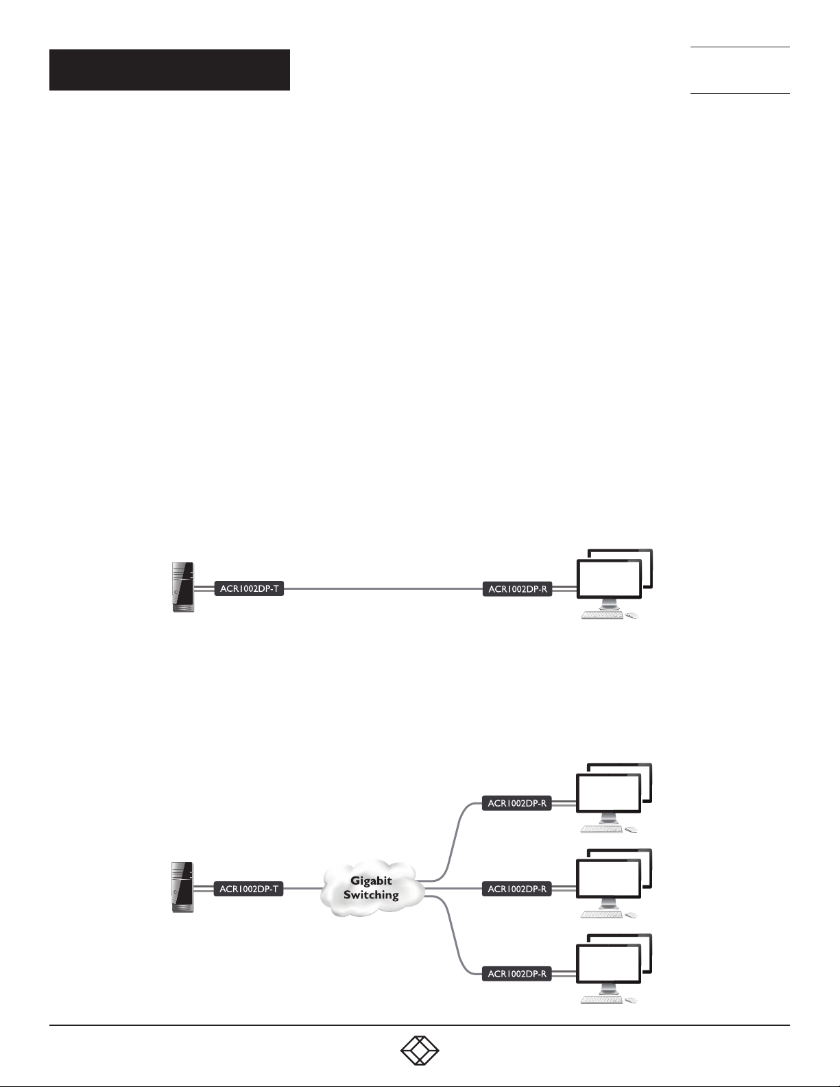
Agility units can be linked in two mains ways: Direct or Networked.
DIRECT LINKING
Where Agility transmitters and receivers are directly linked to each other, very little configuration action is required, provided that
they both have their factory default settings in place - just link them together. If the standard settings have been changed in a
previous installation, you merely need to perform a manual factory reset on each unit - see page 24.
NETWORKED LINKING
Where Agility units are connected via networked links, you can either configure them individually, or configure them collectively
using an iPATH server:
• Configuring networked units individually - In the absence of an iPATH server, unallocated Agility units have the ability to locate
each other. You can alter settings via the OSD on the console connected to the receiver by pressing CTRL + ALT + C.
• Configuring networked units collectively - The iPATH server allows you to configure, control and coordinate any number of
transmitters and receivers from a single application.
Note: If you are using one or more transmitters within
an installation managed by an iPATH server, the iPATH
server must be running firmware version 4.9 or above.
IMPORTANT: When using iPATH to configure Agility units, it is
vital that all units that you wish to locate and control are set
to their factory default settings. Otherwise they will not be
located by the iPATH server. If necessary, perform a manual
factory reset on each Agility unit.
1. 8 7 7. 8 7 7. 2 2 69 BLACKBOX.COM
7
Page 8
NEED HELP?
LEAVE T HE TECH TO U S
LIVE 24/7
TECHNICAL
SUPPORT
1.877.877.2269
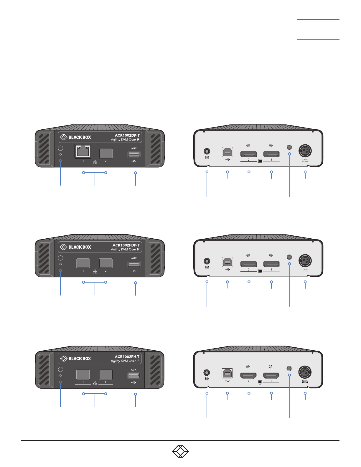
AGILITY ACR1002DP, ACR1002FDP AND ACR1002FH FEATURES
The transmitter and receiver modules are housed within durable, vented enclosures with connectors situated on the front and
rear panels. FDP and FH-T model variants have two SFP ports rather than a mix of CATx and SFP. FH-T model variants also have
two HDMI™ video ports rather than DisplayPort™, but are otherwise identical. Note: ACR1002FH-T transmitters do not support
either the CEC or HDCP protocols.
AGILITY TRANSMITTER MODULES
ACR1002DP-T model
Reset
switch and status
indicator
ACR1002FDP-T model
Reset
switch and status
indicator
ACR1002FH-T model
CATx and
SFP link
ports
2 x SFP link
ports
USB AUX port
(for use with USB-to-
serial converters)
USB AUX port
(for use with USB-to-
serial converters)
Analog
audio in
Analog
audio in
USB
USB
Secondary
DisplayPort
video in
Secondary
DisplayPort
video in
Primary
DisplayPort
video in
Primary
DisplayPort
video in
Status
indicator
Status
indicator
Power
in
Power
in
USB
Reset
switch and status
indicator
8
2 x SFP link
ports
USB AUX port
(for use with USB-to-
serial converters)
1. 8 7 7. 8 7 7. 2 2 69 BLACKBOX.COM
Analog
audio in
Secondary
HDMI
video in
Primary
HDMI
video in
indicator
Power
in
Status
Page 9
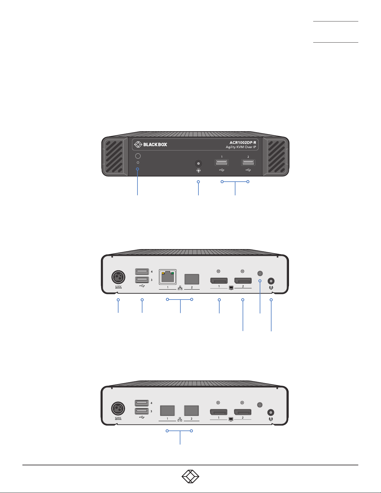
ACR1002DP-R and
ACR1002FDP-R models
AGILITY RECEIVER MODULES
NEED HELP?
LEAVE T HE TECH TO U S
LIVE 24/7
TECHNICAL
SUPPORT
1.877.877.2269
ACR1002DP-R model
ACR1002FDP-R model
Reset
switch and status
indicator
Power
in
USB
ports
Combined
analog audio
headphone/
mic/headset
CATx and
SFP link ports
port
Primary
display
USB
ports
Secondary
display
Status
indicator
Analog
audio line
out
2 x SFP link
ports
1. 8 7 7. 8 7 7. 2 2 69 BLACKBOX.COM
9
Page 10

NEED HELP?
LEAVE T HE TECH TO U S
LIVE 24/7
CHAPTER 3: INSTALLATION
TECHNICAL
SUPPORT
1.877.877.2269
LOCATIONS
Please consider the following important points when planning the position of the modules:
• Situate the transmitter module close to the system to which it will be connected and near to a source of mains power. Place the
receiver module in similar close proximity to the peripherals that it will connect with, plus a source of mains power.
• Consult the precautions listed within the supplied safety leaflet.
• Connections do not need to be carried out in the order given within this guide, however, where possible, connect the power in
as the final step.
Suitable for installation in Information Technology Rooms in accordance with Article 645 of the National Electrical Code and
NFPA 75.
Peut être installé dans des salles de matériel de traitement de l’information conformément à l’article 645 du National Electrical
Code et à la NFPA 75.
10
1. 8 7 7. 8 7 7. 2 2 69 BLACKBOX.COM
Page 11
NEED HELP?
LEAVE T HE TECH TO U S
LIVE 24/7
TECHNICAL
SUPPORT
1.877.877.2269
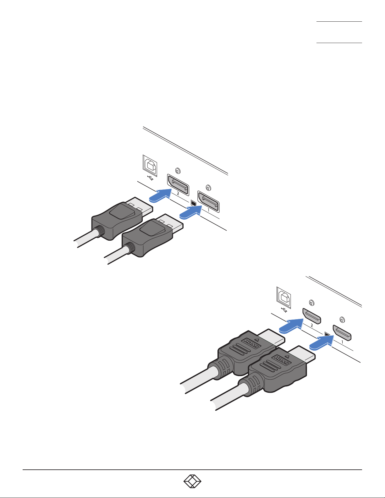
TRANSMITTER VIDEO LINK(S)
The transmitter supports a single DisplayPort™ connection at up to 2560x1600@60Hz or two connections, each up to
1920x120 0@6 0Hz. Note: ACR1002FH-T transmitters do not support either the CEC or HDCP protocols.
TO MAKE A VIDEO LINK
1 Connect your digital video link cable(s) to the DisplayPort/HDMI socket(s) on the TX unit rear panel:
ACR1002DP-T AND
ACR1002FDP-T
(DISPLAYPORT) MODELS
To secondary
video output
port
To primary
video output
port
ACR1002FH-T
(HDMI) MODELS
To secondary
video output
port
To primary
video output
port
2 Connect the plug at the other end of the cable(s) to the corresponding video output socket(s) of the host computer.
1. 8 7 7. 8 7 7. 2 2 69 BLACKBOX.COM
11
Page 12
NEED HELP?
LEAVE T HE TECH TO U S
LIVE 24/7
TECHNICAL
SUPPORT
1.877.877.2269
TRANSMITTER AUDIO LINKS
Audio is supported in the initial product release solely via the USB link with the host computer. In subsequent firmware updates
further audio capabilities will be added.
Conversion between the USB derived digital audio and the receiver compatible audio format audio is carried out at the
transmitter.
TRANSMITTER USB LINKS
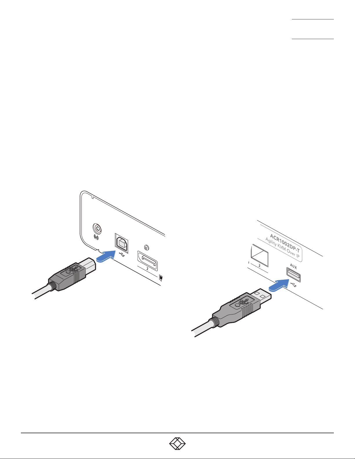
The transmitter has a USB type B socket on the rear panel to link with the host computer. Additionally, the unit also has a type A
socket on the front panel to allow an optional USB-to-serial converter device to be attached.
TO MAKE A USB LINK
1 Connect the type B connector of the supplied USB cable
to the USB port 1 on the transmitter rear panel.
USB link from
host computer
2 Connect the type A connector of the supplied cable to a
vacant USB socket on the host computer.
RS232 SERIAL SUPPORT
To support RS232 serial connections, use third-party USB-toserial adapters on both the transmitters and receivers.
TO ATTACH A USB-TO-SERIAL CONVERTER
1 If required, connect a USB-to-serial converter to the AUX
port on the transmitter front panel.
12
2 Connect an accompanying USB-to-serial converter to a
vacant USB socket on the receiver.
1. 8 7 7. 8 7 7. 2 2 69 BLACKBOX.COM
Page 13
NEED HELP?
LEAVE T HE TECH TO U S
LIVE 24/7
TECHNICAL
SUPPORT
1.877.877.2269
TRANSMITTER POWER IN
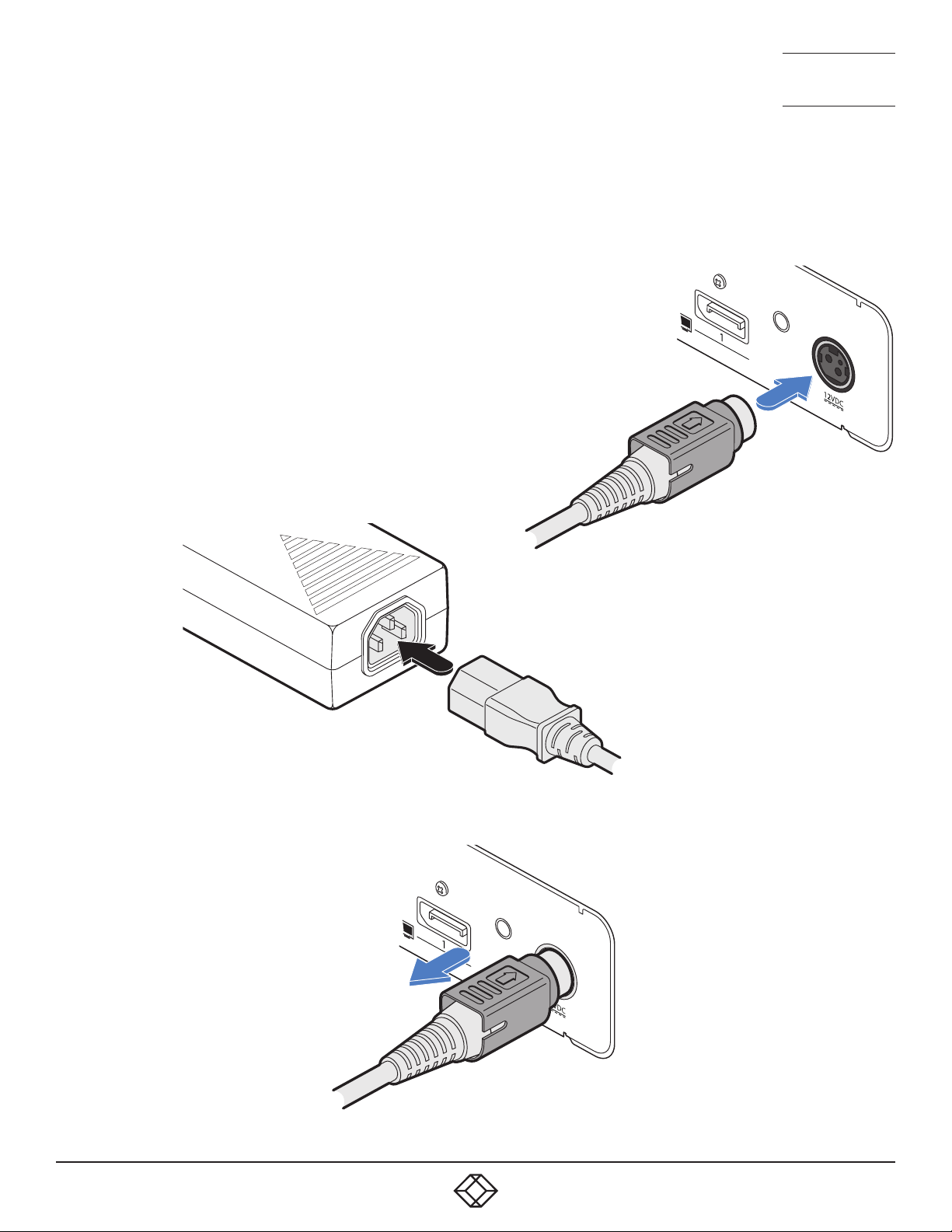
Each unit is supplied with a power adapter and country-specific power cord. The supplied power adapter uses a locking-type
plug to help prevent accidental disconnection; follow the instructions shown on the right when disconnecting a power adapter.
TO CONNECT THE POWER ADAPTER
1 Attach the output plug of the supplied power adapter to the power input
socket on the right side of the rear panel. As you insert the plug, pull back
slightly on the outer body to assist the locking mechanism until the plug is
fully inserted.
From the
power
2 Insert the IEC connector of the supplied country-specific
power cord to the socket of the power adapter.
adapter
3 Connect the power cord to a nearby mains supply socket.
TO DISCONNECT THE POWER ADAPTER
1 Isolate the power adapter from the mains
supply.
2 Grasp the outer body of the power adapter
plug where it connects with the node.
3 Gently pull the body of the outer plug away
from the node. As the body of the plug
slides back, it will release from the socket
and you can fully withdraw the whole plug.
IMPORTANT: Please read and
adhere to the electrical safety
information given within
the supplied safety leaflet.
In particular, do not use an
unearthed power socket or
extension cable.
Note: Both the modules and
the power supplies generate
heat when in operation and will
become warm to the touch. Do
not enclose them or place them
in locations where air cannot
circulate to cool the equipment.
Do not operate the equipment in
ambient temperatures exceeding
40 degrees Centigrade (104
degrees Fahrenheit). Do not
place the products in contact
with equipment whose surface
temperature exceeds 40 degrees
Centigrade (104 degrees
Fahrenheit).
Gently pull back the plug outer
body to release the lock.
1. 8 7 7. 8 7 7. 2 2 69 BLACKBOX.COM
13
Page 14
NEED HELP?
LEAVE T HE TECH TO U S
LIVE 24/7
TECHNICAL
SUPPORT
1.877.877.2269
TRANSMITTER/RECEIVER HIGH SPEED LINKS
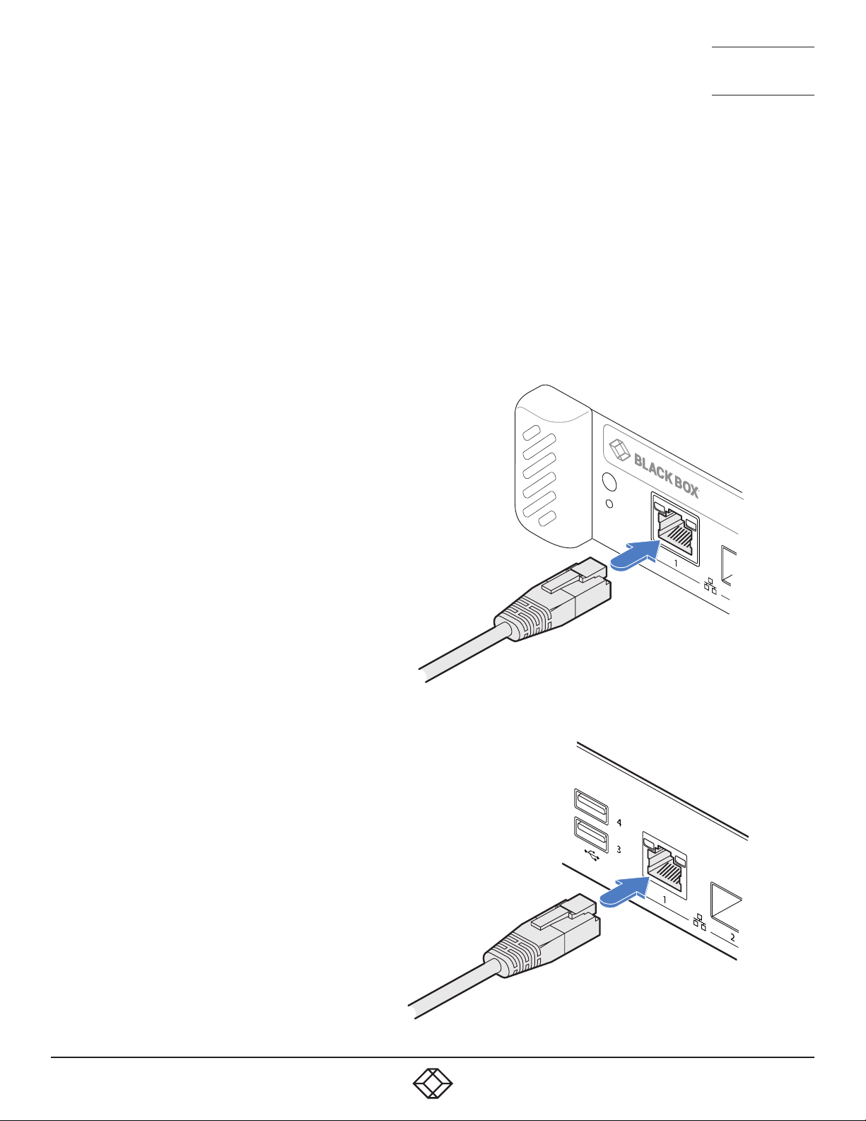
Agility units can be either connected directly to each other or via a high speed (up to 1GbE) network. Links can be made:
• Using the in-built CATx ports (see below),
• Using additional CATx connections within the SFP ports (see next page),
• Using the SFP ports with optional fiber (FCoE) modules (see page 16).
• Using the dual SFP ports with optional fiber (FCoE) modules on ACR1002FDP variants (see page 17).
TEAMING
Agility units are ready to automatically invoke teaming whenever the CATx and SFP (with either CATx or fiber modules installed)
ports are both used to link transmitters and receivers. Teaming potentially doubles the available bandwidth for video intensive
applications and also provides redundancy in case one link is lost.
TO LINK USING THE IN-BUILT CATX PORT
1 Insert a suitable CATx cable into the RJ45 port on the front panel of
the transmitter.
2 Connect the other end(s) of the CATx cable(s) to either a network
switch or...
Transmitter
front panel
14
CATx link
cable
Receiver
rear panel
... connect directly to the receiver - to the
RJ45 port on the rear panel of the receiver.
CATx link
cable
1. 8 7 7. 8 7 7. 2 2 69 BLACKBOX.COM
Page 15
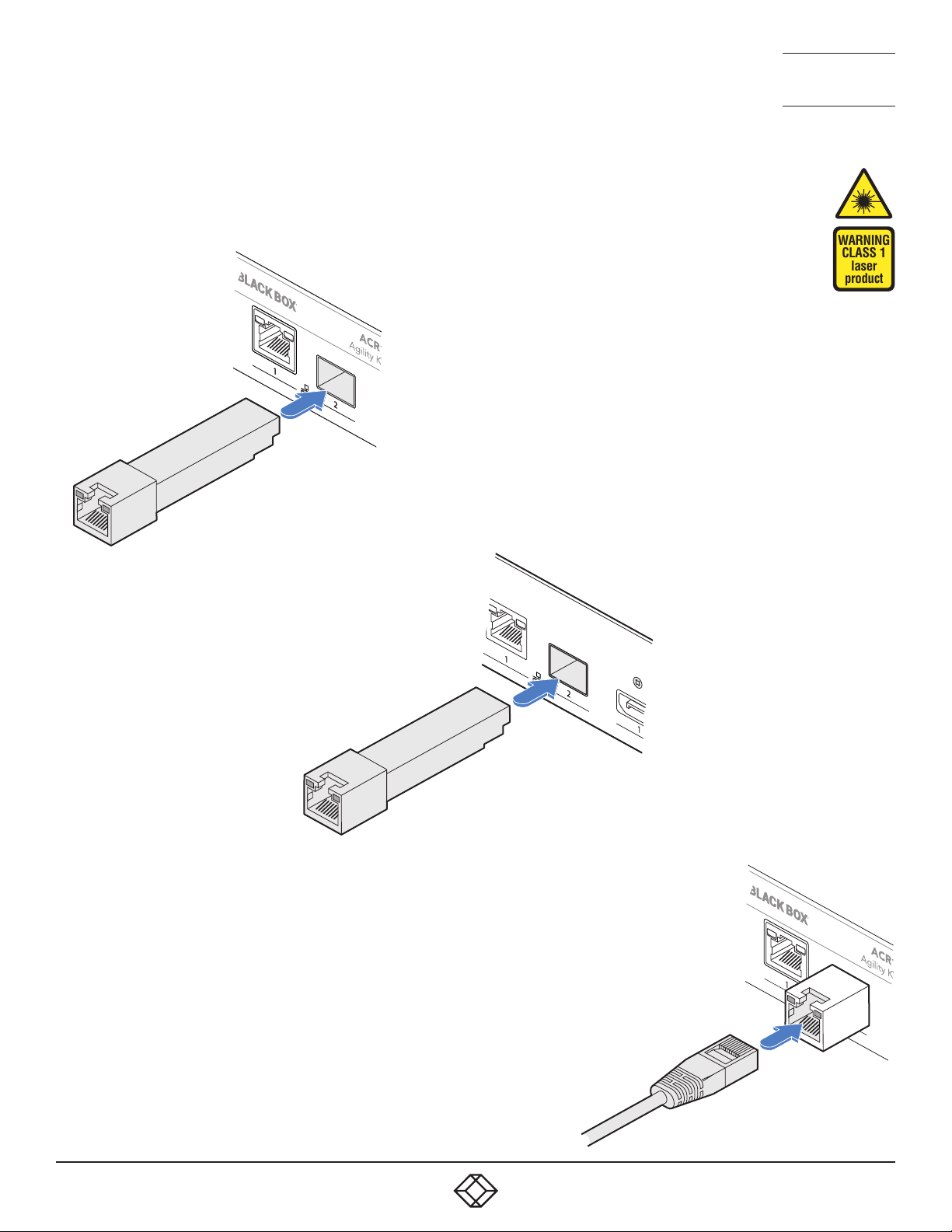
TO INSTALL ADDITIONAL CATX MODULES
1 Insert the appropriate optional SFP module into socket 2 located on the
front panel of the transmitter...
Transmitter
front panel
NEED HELP?
LEAVE T HE TECH TO U S
LIVE 24/7
TECHNICAL
SUPPORT
1.877.877.2269
WARNING
CLASS 1
laser
product
CATx SFP
module
Receiver
rear panel
...and the rear panel of the
receiver:
CATx SFP
module
2 Make your CATx connection(s)
between the SFP module and
either the other Agility unit or a
suitable network switch.
CATx link
cable
1. 8 7 7. 8 7 7. 2 2 69 BLACKBOX.COM
15
Page 16
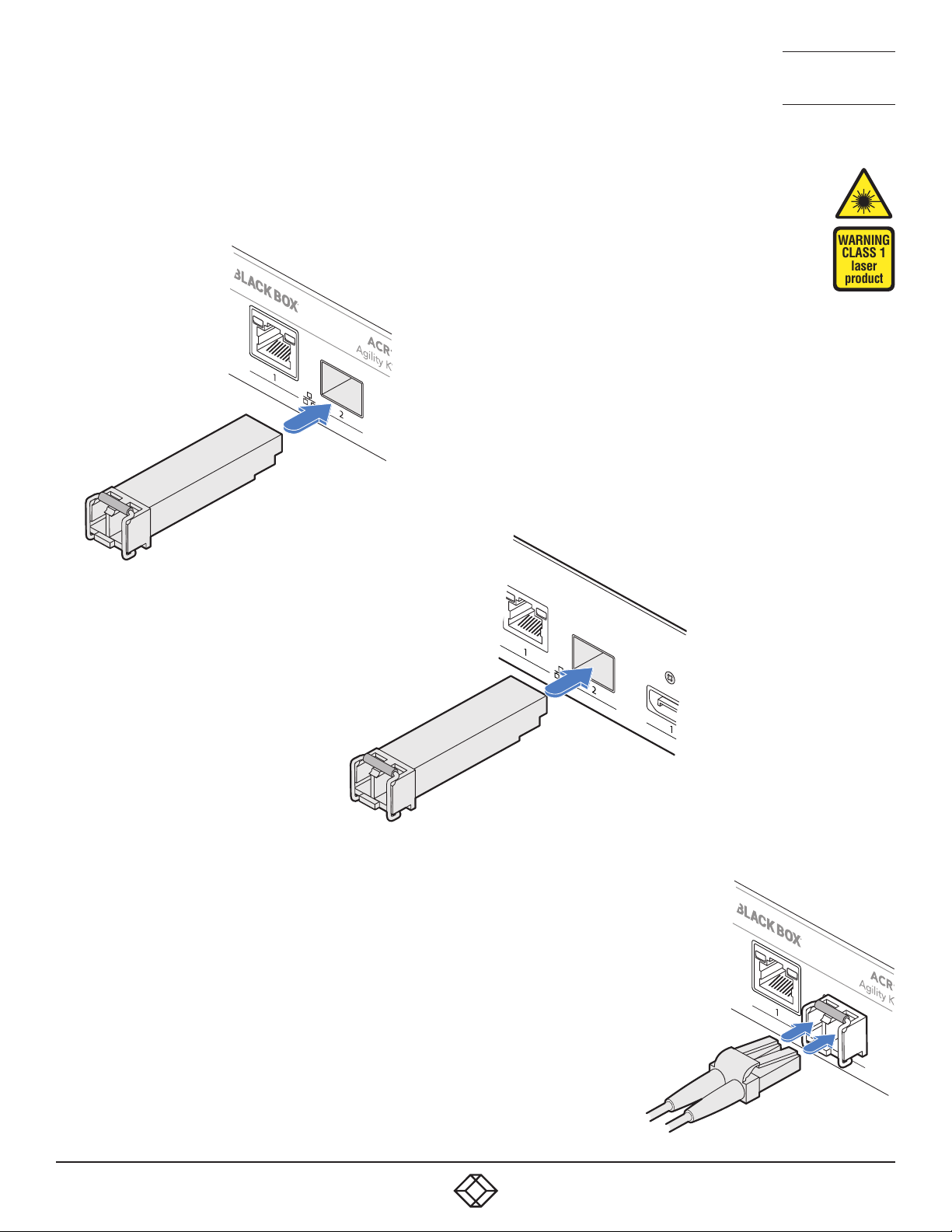
TO LINK AGILITY ACR1002DP UNITS VIA FIBER MODULES
1 Insert the appropriate optional SFP module into socket 2 located on
the front panel of the transmitter...
Transmitter
front panel
Fiber SFP
module
NEED HELP?
LEAVE T HE TECH TO U S
LIVE 24/7
TECHNICAL
SUPPORT
1.877.877.2269
WARNING
CLASS 1
laser
product
...and the rear panel of
the receiver:
2 Make your fiber connection(s) between
the SFP module and either the other
Agility unit or a suitable fiber network
switch.
3 Close the latch over the link connectors
to lock them into place.
Receiver
rear panel
Fiber SFP
module
16
Transmit and receive
ber links
1. 8 7 7. 8 7 7. 2 2 69 BLACKBOX.COM
Page 17
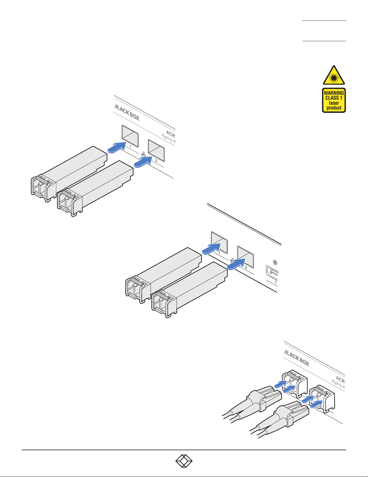
TO LINK AGILITY ACR1002FDP UNITS VIA FIBER MODULES
1 Insert the appropriate optional SFP modules into sockets 1 and 2
located on the front panel of the transmitter...
Transmitter
front panel
NEED HELP?
LEAVE T HE TECH TO U S
LIVE 24/7
TECHNICAL
SUPPORT
1.877.877.2269
WARNING
CLASS 1
laser
product
Fiber SFP
modules
Receiver
rear panel
...and the rear panel of
the receiver:
Fiber SFP
modules
2 Make your fiber connection(s) between
the SFP modules and either the other
Agility unit or a suitable fiber network
switch.
3 Close the latch over the link connectors
to lock them into place.
1. 8 7 7. 8 7 7. 2 2 69 BLACKBOX.COM
Transmit and receive
ber links
17
Page 18
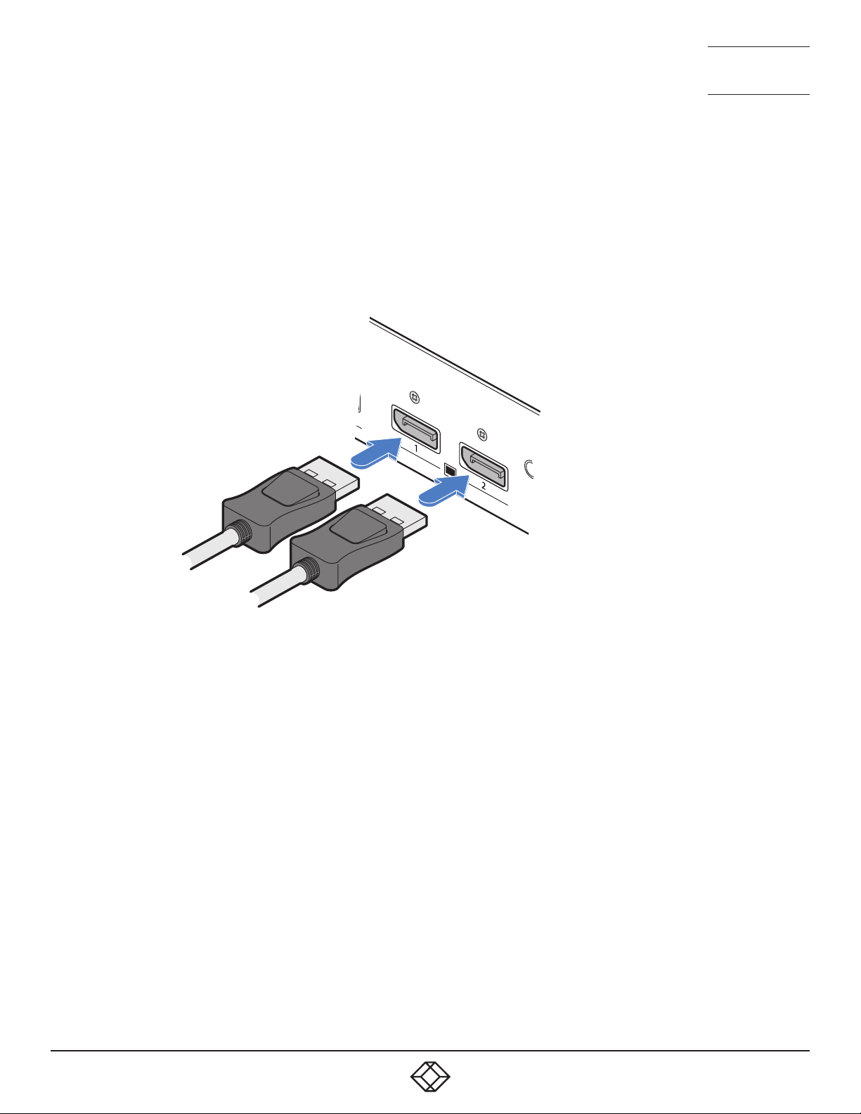
RECEIVER VIDEO DISPLAYS
The receiver supports a single DisplayPort™ connection at up to
2560x1600@60Hz or two connections, each up to 1920x1200@60Hz.
Note: If required, DP++ to HDMI or DP++ to DVI passive adapters can be used
on a receiver to allow a HDMI or DVI monitor to be connected instead of a
DisplayPort monitor.
TO CONNECT VIDEO DISPLAYS
1 Connect the lead from the primary
video display to the DisplayPort socket
marked ‘1’ on the receiver rear panel:
NEED HELP?
LEAVE T HE TECH TO U S
LIVE 24/7
TECHNICAL
SUPPORT
1.877.877.2269
To primary
video
display
To secondary
video display
2 If required, connect the lead from the second video display to the
DisplayPort socket marked ‘2’ on the receiver rear panel.
18
1. 8 7 7. 8 7 7. 2 2 69 BLACKBOX.COM
Page 19

NEED HELP?
LEAVE T HE TECH TO U S
LIVE 24/7
TECHNICAL
SUPPORT
1.877.877.2269
RECEIVER AUDIO DEVICES
The receiver can support headphones and a mono microphone via its front panel jack socket. On the rear panel a line out jack
socket can be used to drive powered speakers. A USB link must be made between the transmitter and the host computer for
audio to operate.
TO CONNECT HEADPHONES AND/OR HEADSETS
1 Connect your chosen audio
device to the 3.5mm socket
labeled on the front
panel. Please see below for a
compatibility list.
To headphones/
headset
HEADPHONE, HEADSET AND MICROPHONE SUPPORT
The combined jack socket can accommodate
any standard stereo headphones; it can also
support headsets which conform to the CTIA/AHJ
standard. The lesser-used OMTP standard is not
directly supported as its microphone and ground
connections are swapped. If used, the audio may be
distorted and/or the mic will not operate. Suitable
OMTP to CTIA/AHJ converters are available.
TO CONNECT AMPLIFIED SPEAKERS
1 Connect your speakers to
the 3.5mm line out socket
on the rear panel.
To speakers
SUPPORTED DEVICES
All standard headphones and some headsets are directly
supported, others require a suitable converter. It can be
difficult to distinguish different headset standards, however,
some (but not all) CTIA/AHJ devices use white dividers on their
jack plugs.
SUPPORTED
• Stereo headphones - Yes
• Mono microphone – Supported when used with an adapter
• CTIA/AHJ-compliant headset with mic - Yes
• CTIA/AHJ-compliant adapter with mic and headphones
plugged in - Yes
NOT SUPPORTED
• OMTP-compliant headset with mic – Not supported directly
• OMTP-compliant adapter with headset plugged in – Not
supported directly
1. 8 7 7. 8 7 7. 2 2 69 BLACKBOX.COM
19
Page 20
NEED HELP?
LEAVE T HE TECH TO U S
LIVE 24/7
TECHNICAL
SUPPORT
1.877.877.2269
RECEIVER USB DEVICES
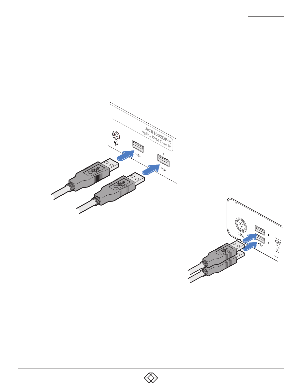
The receiver has two USB ports on the front panel to which peripherals may be connected.
To connect more than two peripherals, a USB hub may be used. The total current that may be drawn from the USB ports is 1.2A,
which should be sufficient for a keyboard, mouse (no more than 100mA each) and any two other devices (500mA maximum
each). If more power for USB devices is required, use a powered USB hub.
TO CONNECT USB DEVICES
1 Connect the lead from the device(s)
to either of the two USB sockets on
the front panel of the receiver...
To USB peripherals
...and/or either of the two USB
sockets on the rear panel.
To USB peripherals
RS232 SERIAL SUPPORT
To support RS232 serial connections, use third-party USB-to-serial adapters on both the transmitter and receiver.
20
1. 8 7 7. 8 7 7. 2 2 69 BLACKBOX.COM
Page 21
NEED HELP?
LEAVE T HE TECH TO U S
LIVE 24/7
TECHNICAL
SUPPORT
1.877.877.2269
RECEIVER POWER IN
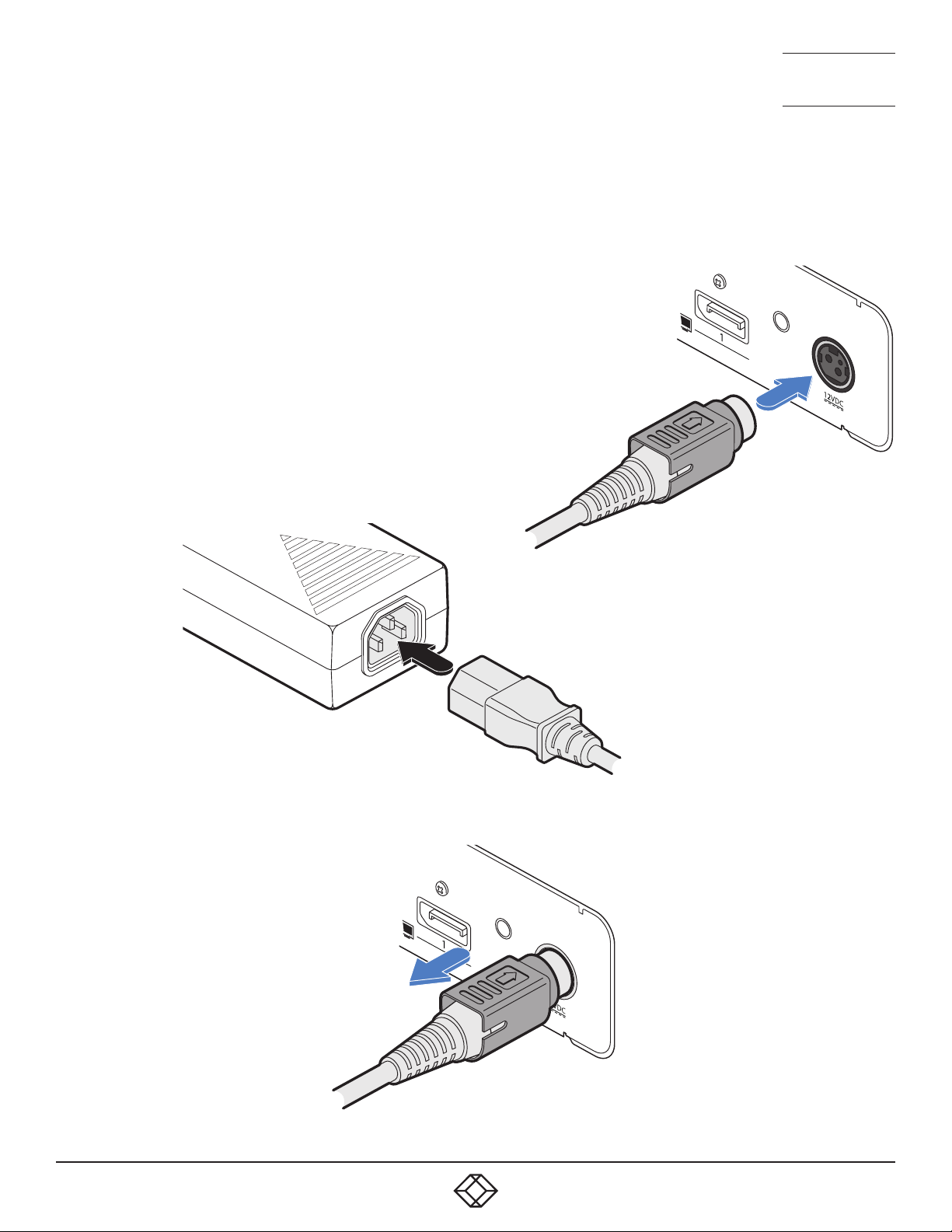
Each unit is supplied with a power adapter and country-specific power cord. The supplied power adapter uses a locking-type
plug to help prevent accidental disconnection; follow the instructions shown on the right when disconnecting a power adapter.
TO CONNECT THE POWER ADAPTER
1 Attach the output plug of the supplied power adapter to the power input
socket on the right side of the rear panel. As you insert the plug, pull back
slightly on the outer body to assist the locking mechanism until the plug is
fully inserted.
From the
power
2 Insert the IEC connector of the supplied country-specific
power cord to the socket of the power adapter.
adapter
3 Connect the power cord to a nearby mains supply socket.
TO DISCONNECT THE POWER ADAPTER
1 Isolate the power adapter from the mains
supply.
2 Grasp the outer body of the power adapter
plug where it connects with the node.
3 Gently pull the body of the outer plug away
from the node. As the body of the plug
slides back, it will release from the socket
and you can fully withdraw the whole plug.
IMPORTANT: Please read and
adhere to the electrical safety
information given within
the supplied safety leaflet.
In particular, do not use an
unearthed power socket or
extension cable.
Note: Both the modules and
the power supplies generate
heat when in operation and will
become warm to the touch. Do
not enclose them or place them
in locations where air cannot
circulate to cool the equipment.
Do not operate the equipment in
ambient temperatures exceeding
40 degrees Centigrade (104
degrees Fahrenheit). Do not
place the products in contact
with equipment whose surface
temperature exceeds 40 degrees
Centigrade (104 degrees
Fahrenheit).
Gently pull back the plug outer
body to release the lock.
1. 8 7 7. 8 7 7. 2 2 69 BLACKBOX.COM
21
Page 22
NEED HELP?
LEAVE T HE TECH TO U S
LIVE 24/7
TECHNICAL
CHAPTER 4: CONFIGURATION
SUPPORT
1.877.877.2269
AGILITY CONFIGURATION VIA WEB PAGES
Each Agility unit hosts its own internal set of web pages which contain all configuration details and settings (see also Start of
Life, shown right). You will need to use a computer connected to the same network as each Agility unit to access the web pages.
Additionally, on the console attached to the receiver, you can access its configuration details via the On Screen Display (OSD) by
pressing CTRL + ALT + C (or by tapping the icon on the touchscreen) - see page 30.
TO MANUALLY CONFIGURE AGILITY UNITS VIA THEIR WEB PAGES
Run a web browser on your computer and enter the IP address of the required Agility unit:
The default addresses (if using port 1) are: Transmitter: https://169.254.1.33
Receiver: https://169.254.1.32
The default addresses (if using port 2) are: Transmitter: https://169.254.1.43
Receiver: https://169.254.1.42
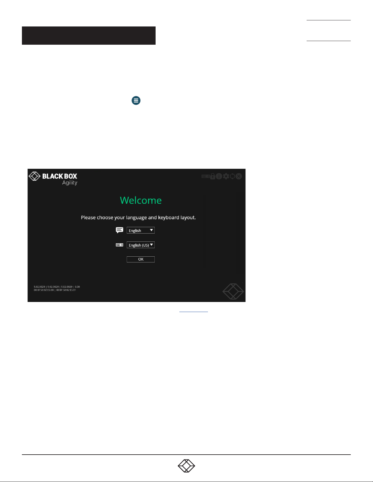
The opening page should be displayed:
For explanations of the options within each page, please see Appendix A.
22
1. 8 7 7. 8 7 7. 2 2 69 BLACKBOX.COM
Page 23
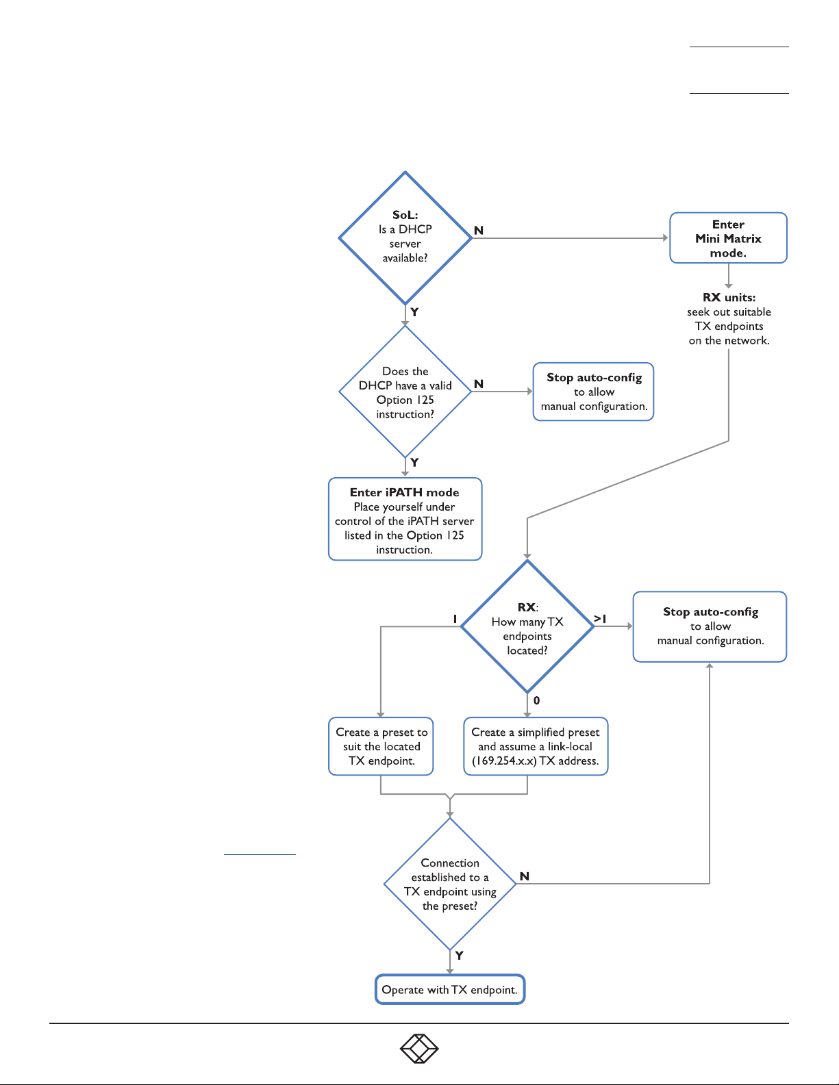
START OF LIFE: IPATH OR POINT TO POINT CONFIGURATION
To streamline initial configuration processes,
all Agility ACR1002DP units employ a Start
of Life (SoL) procedure when they are in an
unconfigured state, either because they
are new or because they have undergone a
factory reset.
When an unconfigured Agility ACR1002DP
unit boots, its SoL procedure will guide it to
automatically determine which of two modes
it should adopt:
• iPATH mode - place itself into the control
of a specific iPATH server on the network,
whereupon the Agility unit will be assigned
suitable configuration details to fit within
the network of similar units.
• Mini Matrix (P2P) mode - place itself into
Mini Matrix (Point to Point) mode to allow
manual configuration of links with other
Agility units.
The SoL procedure follows this basic logic
flow to determine the correct mode:
NEED HELP?
LEAVE T HE TECH TO U S
LIVE 24/7
TECHNICAL
SUPPORT
1.877.877.2269
Note: If an iPATH server is present on the
network then the modules don’t have to
be within SoL procedure for it to be placed
under iPATH control.
Once the mode has been set to iPATH
control, an Agility unit will remain operating
that way until it undergoes a factory reset. If
set to P2P mode, an Agility unit will remain
thus until it undergoes a factory reset or is
discovered by an iPATH server.
Note: When the modules enter Mini Matrix
mode, you can cancel auto-SoL at any point
by pressing Ctrl-Alt-C.
1. 8 7 7. 8 7 7. 2 2 69 BLACKBOX.COM
23
Page 24
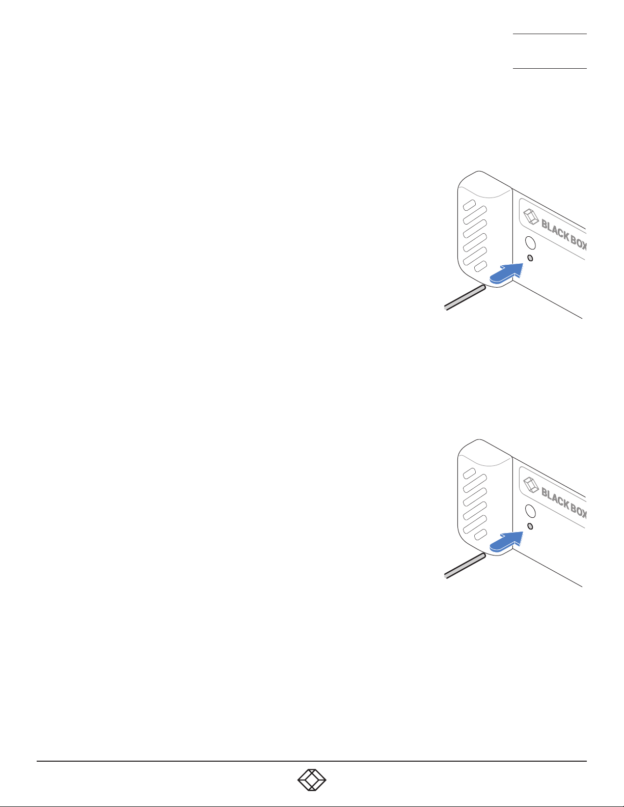
PERFORMING A MANUAL FACTORY RESET
A factory reset returns Agility unit to its default configuration.
TO PERFORM A MANUAL FACTORY RESET
1 Power on the Agility unit.
2 Use a long narrow implement (e.g., a straightened-out paper clip) to press-and-hold
the recessed reset button on the front panel for roughly ten seconds until the status
indicator turns blue (Note: alternating red/green indications will occur during the ten
second period while the button is still pressed).
3 Release the reset switch. The indicator will change to red for a short time (less than
ten seconds) and then back to blue while the Agility unit performs the reset and
should then change to an alternative color, usually orange initially, signifying that the
operation is complete.
Note: If you are performing a factory reset and intend to disconnect the power
immediately after the reset, you must wait at least 30 seconds after you have released
the reset button for it to complete the process.
NEED HELP?
LEAVE T HE TECH TO U S
LIVE 24/7
TECHNICAL
SUPPORT
1.877.877.2269
PLACING THE DEVICE INTO RECOVERY MODE
Recovery mode may allow an Agility unit to be diagnosed or upgraded in the event of the
main mode being non-operational.
TO BOOT THE DEVICE INTO RECOVERY MODE
1 Power on the Agility unit.
2 Use a long narrow implement (e.g., a straightened-out paper clip) to press-and-hold
the recessed reset button on the front panel (for less than ten seconds) until the
status indicator starts alternating red/green. Note: A solid blue indication will occur
after the ten second period.
3 Release the reset switch. The indicator will change to red for a short time (less than
ten seconds) and then alternate red/green signifying that the device is in recovery
mode. Note: If the indicator turns blue, then a factory reset has been performed
instead; the device will not be in recovery mode; and the operation will need to be
attempted again.
24
1. 8 7 7. 8 7 7. 2 2 69 BLACKBOX.COM
Page 25
NEED HELP?
LEAVE T HE TECH TO U S
LIVE 24/7
TECHNICAL
SUPPORT
1.877.877.2269
CONFIGURING DUAL TOUCHSCREENS
When a single touchscreen is used with a receiver, it should operate correctly as soon as the USB link is made between the
screen and the receiver. However, if two touchscreens are installed it may be necessary to instruct the receiver which screen to
correctly attribute to each USB input.
TO ATTRIBUTE DUAL TOUCHSCREENS
1 Access the Configuration pages on the receiver - see page 30.
2 Click the Ports entry from the list of pages on the left side.
3 Click the USB page icon: to display the following:
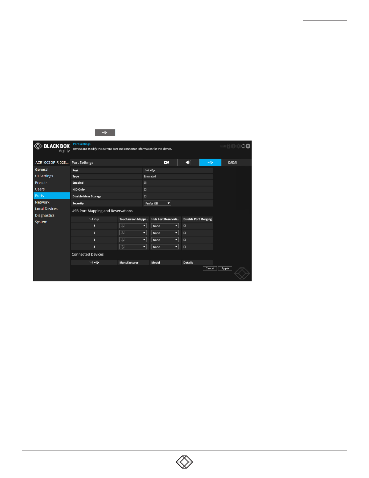
4 In the USB Port Mapping and Reservations section, match the primary touchscreen to the port number (1-4) that its USB cable
is connected to.
5 Repeat step 4 for the secondary touchscreen.
6 Click the Apply button and exit from the configuration pages.
1. 8 7 7. 8 7 7. 2 2 69 BLACKBOX.COM
25
Page 26
NEED HELP?
LEAVE T HE TECH TO U S
LIVE 24/7
TECHNICAL
SUPPORT
1.877.877.2269
CREATING AN UNMANAGED MATRIX
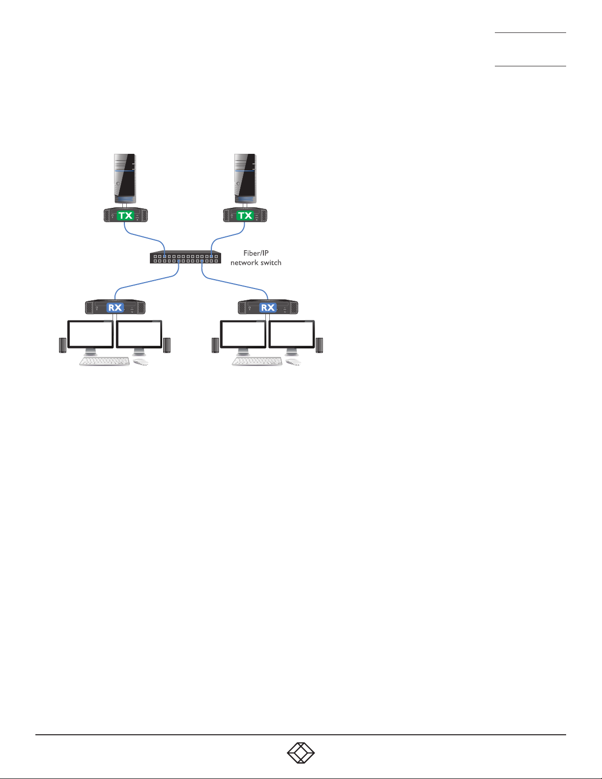
Although Agility units are most often organized and managed by a central iPATH server, it is possible to create small networks of
Agility units, most often in matrix arrangements, i.e., multiple transmitters and receivers which can freely cross-connect.
This method of connection works well for small numbers of transmitters and receivers, but will become more difficult to manage
as more units are attached. The maximum number of transmitter sources that can be made available to any receiver is sixteen.
TO CREATE AN UNMANAGED MATRIX
1 Connect Agility transmitters and receivers (with their various hosts and peripherals) to a suitable switch, as described in the
Installation section - see page 10.
Note: If any device was previously managed by iPATH, then it will need to be given a factory reset before continuing with this
procedure. There must not be an iPATH connected on the matrix network. Otherwise, when such devices undergo a factory
reset, they will automatically revert to iPATH control.
You now need to perform the following procedure on each receiver in turn:
2 Access the Configuration pages - see page 30.
3 Click the Transmitters option from the list on the left side. This page will list all of the available transmitters which are not
under iPATH control. See page 42.
4 Click the Presets option from the list on the left side. Use this page to add each transmitter to the list of presets for the receiver
that you are editing. See page 36.
TO USE THE MATRIX
• On each receiver, use the OSD to access the required transmitters in the usual manner. See page 30.
26
1. 8 7 7. 8 7 7. 2 2 69 BLACKBOX.COM
Page 27
NEED HELP?
LEAVE T HE TECH TO U S
LIVE 24/7
TECHNICAL
SUPPORT
1.877.877.2269
CREATING AND EDITING PRESETS
Presets allow you to create shortcuts from any Agility receivers to any available Agility transmitters. These are particularly useful
when using an Agility installation that is not under iPATH control.
TO ACCESS THE PRESET CONFIGURATION PAGE
1 On the console keyboard attached to the receiver, access the OSD by pressing
CTRL + ALT + C or tap the icon on the touchscreen.
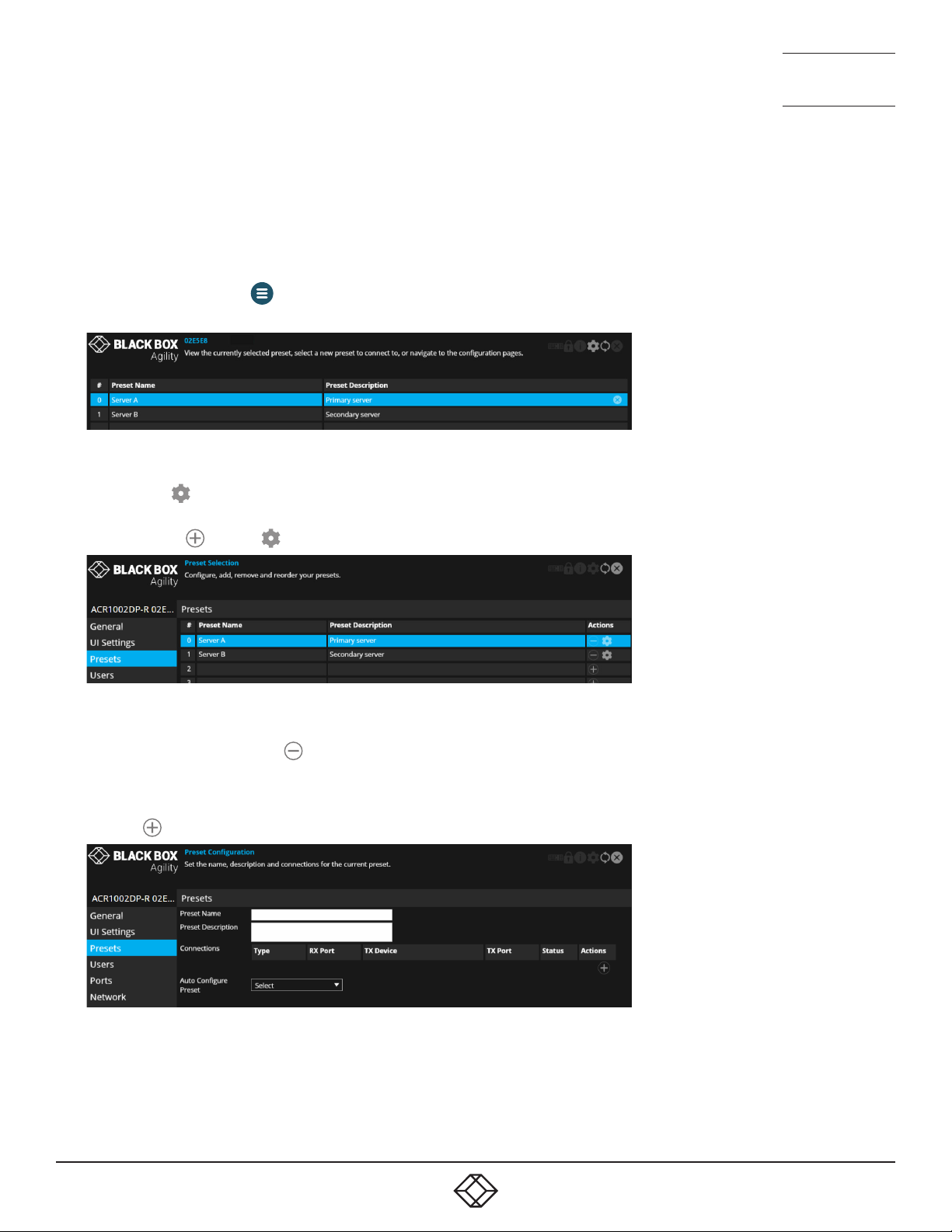
2 The Preset Selection page will be displayed:
Note: The number on the left corresponds to the hotkey sequence that will connect to that channel, e.g., press Ctrl-Alt-4 to
connect to the 4th preset.
3 Click/tap the icon in the top right corner.
4 Choose the Presets option from the list on the left side of the screen. This page will show the same list of presets, but with
options to add ( ) or edit ( ) entries:
TO REMOVE A PRESET
1 Access the Preset configuration page as discussed above.
2 In the Actions column, click the icon for the entry that you wish to remove.
TO ADD A PRESET
1 Access the Preset configuration page as discussed above.
2 Click the icon on the right of a vacant preset entry to display the configuration page:
3 Enter a name and description for the new preset.
continued
1. 8 7 7. 8 7 7. 2 2 69 BLACKBOX.COM
27
Page 28
NEED HELP?
LEAVE T HE TECH TO U S
LIVE 24/7
TECHNICAL
SUPPORT
1.877.877.2269
4 You can now choose how to configure your new preset - Auto or Custom:
• Auto - Click the Auto Configure Preset drop down and choose the Agility transmitter that you wish to connect with. All of the
supported default connections will be configured (on a 1-to-1 basis) between the receiver and chosen transmitter. Click the
Apply button.
• Custom - Configure individual connections (useful when unusual cross connections are required).
1 Click the icon on the right side to add a new connection entry.
2 Check that the correct module is shown in the TX Device column. Click and change this entry, if required.
3 In the Type column, click the Select option and choose the type of connection: Video, Audio, USB or Serial.
4 Click the RX Port drop down and choose the required port.
5 Click the TX Port drop down and choose the port that you wish the current RX port to connect with. If only one option is
available it will be auto-selected.
6 Repeat steps 1 to 5 for each of the required ports.
7 Click the Apply button.
TO EDIT A PRESET
1 Access the Preset configuration page as discussed left.
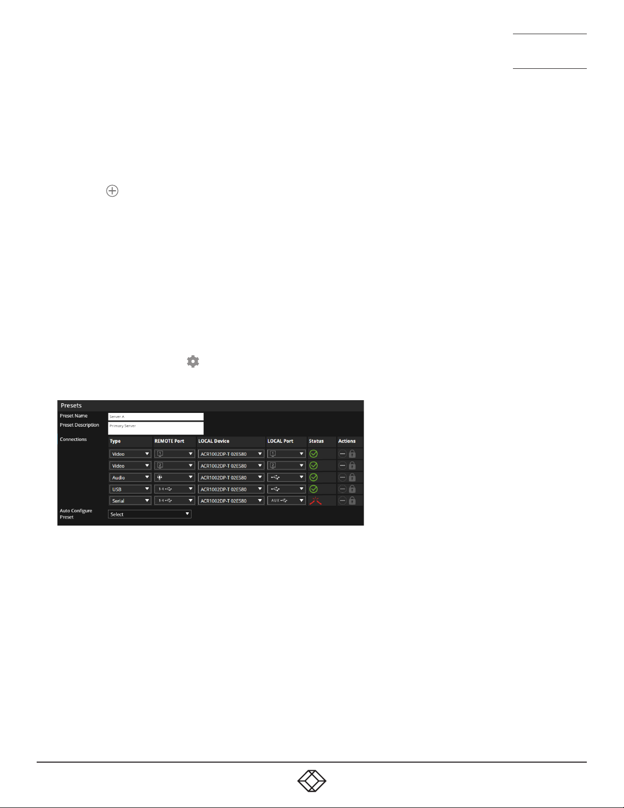
2 In the Actions column, click the icon for the preset entry you wish to edit. An editable list of connections will be shown,
together with their status representations:
3 Make your changes as required and then click the Apply button to save.
TO RE-ORDER PRESETS
1 Access the Preset configuration page as discussed on the previous page.
2 Click and drag a preset to the required position within the list.
For more information about the options and status indications, see page 36.
28
1. 8 7 7. 8 7 7. 2 2 69 BLACKBOX.COM
Page 29

NEED HELP?
LEAVE T HE TECH TO U S
LIVE 24/7
CHAPTER 5: OPERATION
TECHNICAL
SUPPORT
1.877.877.2269
In operation, many Agility installations require no intervention once configured. The transmitters and receivers take care of all
connection control behind the scenes so that you can continue to work unhindered.
INDICATORS
The front and rear panels of each Agility unit feature an indicator capable of producing numerous color and flash patterns to
provide a useful guide to operation. The dual indicators provide the same color and flash patterns.
INDICATOR COLOR AND FLASH PATTERNS
The front and rear panel indicators use varying color and flashing patterns to signal key status:
Off No power.
Green All services present as compared to the configuration required.
Amber Running but video, USB or network link missing (or not connected to another Agility unit).
Red Booting before processor loaded or failed.
Red rapid flash A critical error has been detected that is preventing the device from being used (a malfunction message will
also be displayed within the OSD.)
Blue Factory reset mode active.
Red/green flash Booting into factory recovery mode.
Green/blue flash Upgrade mode active.
Fast green flash Identify mode active.
1. 8 7 7. 8 7 7. 2 2 69 BLACKBOX.COM
29
Page 30
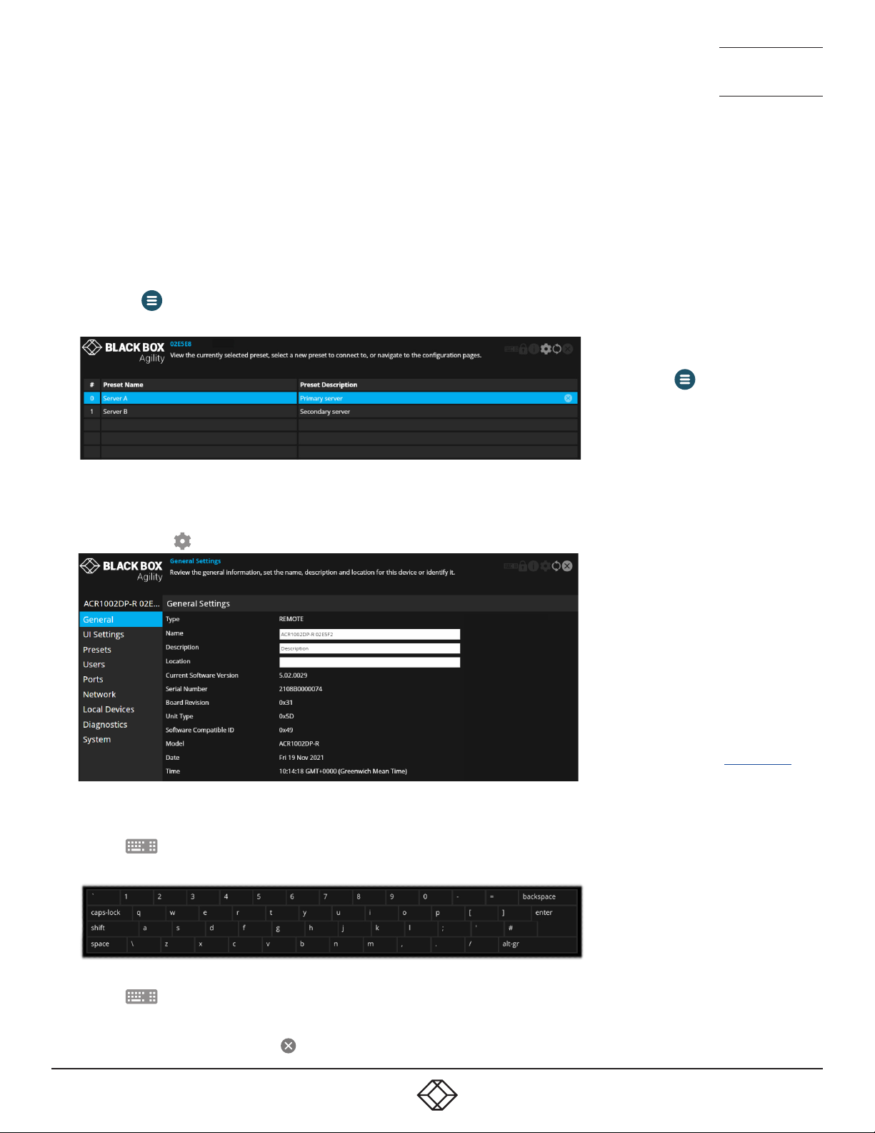
USING THE ON SCREEN DISPLAY
The OSD provides a quick and easy way to access Agility transmitters as well as configuration details.
TO ACCESS THE OSD
1 On the console of your Agility receiver, either:
• Press CTRL + ALT + C on the keyboard,
or
• Tap the icon* on the touchscreen.
2 The Preset Selection page will be displayed:
* To move the icon on your
touchscreen, tap and hold it until it
changes color and then drag it to the
best position.
NEED HELP?
LEAVE T HE TECH TO U S
LIVE 24/7
TECHNICAL
SUPPORT
1.877.877.2269
3 On the preset page, either
• Click/tap a preset entry to connect with the required transmitter,
or
• Click/tap the icon to enter the first Configuration page:
TO USE THE OSD KEYBOARD (WHEN USING A TOUCHSCREEN)
1 Access the OSD as discussed left.
2 Tap the icon in the top right corner.
3 The OSD keyboard will be displayed to assist you when entering text and numerics:
For explanations of the options within
each page, please see Appendix A.
TO HIDE THE OSD KEYBOARD
1 Tap the icon in the top right corner.
TO EXIT THE OSD
1 Either press the Esc key or tap the icon in the top right corner.
30
1. 8 7 7. 8 7 7. 2 2 69 BLACKBOX.COM
Page 31
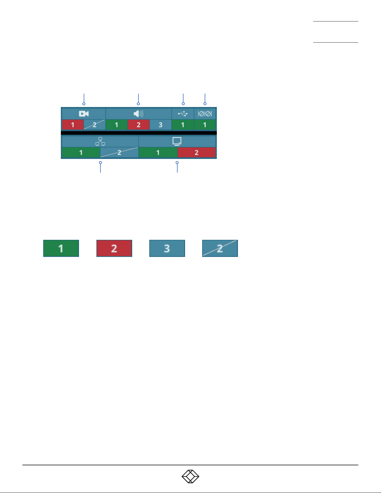
PORT STATUS POPUPS
NEED HELP?
LEAVE T HE TECH TO U S
LIVE 24/7
TECHNICAL
SUPPORT
1.877.877.2269
Video
connection(s)
Network
connection(s)
Audio
connection(s)
USB Serial
Connected
display(s)
These useful status indicators will be displayed in the top left corner (or elsewhere
according to UI Settings) of the primary console display:
• Whenever the OSD is in use,
• If any issues occur with one or more ports (when the OSD is not in use).
The status of each port will be shown as follows:
Operational Not
operational
Not
in use
Port
disabled
1. 8 7 7. 8 7 7. 2 2 69 BLACKBOX.COM
31
Page 32

CHAPTER 6: FURTHER INFORMATION
This chapter contains a variety of information, including the following:
• Getting assistance - see right
• Appendix A - Configuration pages
• Appendix B - Support for analog and digital audio
• Appendix C - Tips for success when networking Agility units
• Appendix D - Troubleshooting
• Appendix E - Glossary
• Appendix F - Fiber/copper modules and cables
• Appendix G - Using the optional Agility rack shelves
• Appendix H - Open source licenses
NEED HELP?
LEAVE T HE TECH TO U S
LIVE 24/7
TECHNICAL
SUPPORT
1.877.877.2269
32
1. 8 7 7. 8 7 7. 2 2 69 BLACKBOX.COM
Page 33
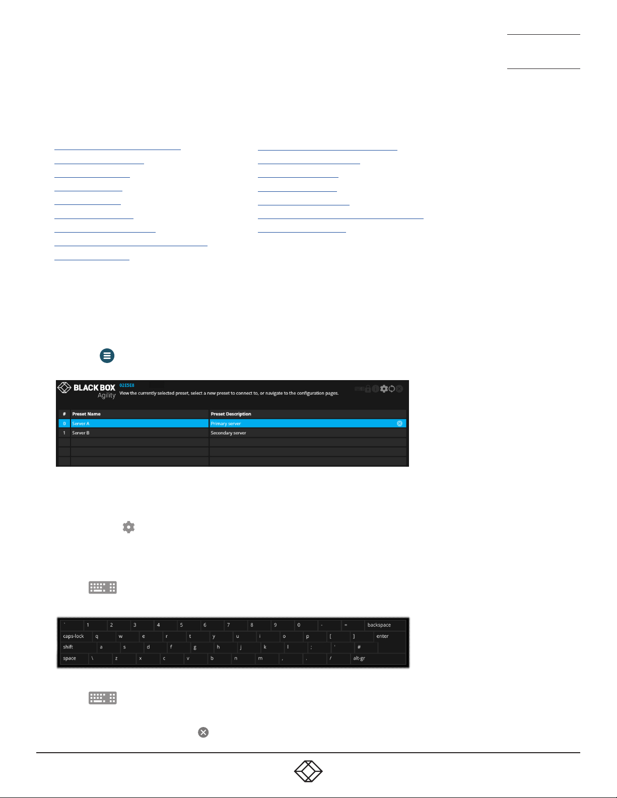
APPENDIX A - CONFIGURATION PAGES
This section covers the web page configuration for the Agility units:
• Receiver - General Information
• Receiver - UI Settings
• Receiver - Presets
• Receiver - Users
• Receiver - Ports
• Receiver - Network
• Receiver - Local Devices
• Receiver - Diagnostics and Statistics
• Receiver - System
TO ACCESS THE OSD
1 On the console of your Agility receiver, either:
• Press CTRL + ALT + C on the keyboard,
or
• Tap the icon* on the touchscreen.
2 The Preset Selection page will be displayed:
• Transmitter - General Information
• Transmitter - UI Settings
• Transmitter - Users
• Transmitter - Ports
• Transmitter - Network
• Transmitter - Diagnostics and Statistics
• Transmitter - System
NEED HELP?
LEAVE T HE TECH TO U S
LIVE 24/7
TECHNICAL
SUPPORT
1.877.877.2269
3 On the preset page, either
• Click/tap a preset entry to connect with the required transmitter,
or
• Click/tap the icon to enter the first Configuration page.
TO USE THE OSD KEYBOARD (WHEN USING A TOUCH SCREEN)
1 Access the OSD as discussed on page 30.
2 Tap the icon in the top right corner of the screen.
3 The OSD keyboard will be displayed to assist you when entering text and numerics:
TO HIDE THE OSD KEYBOARD
1 Tap the icon in the top right corner.
TO EXIT THE OSD
1 Either press the Esc key or tap the icon in the top right corner.
1. 8 7 7. 8 7 7. 2 2 69 BLACKBOX.COM
33
Page 34
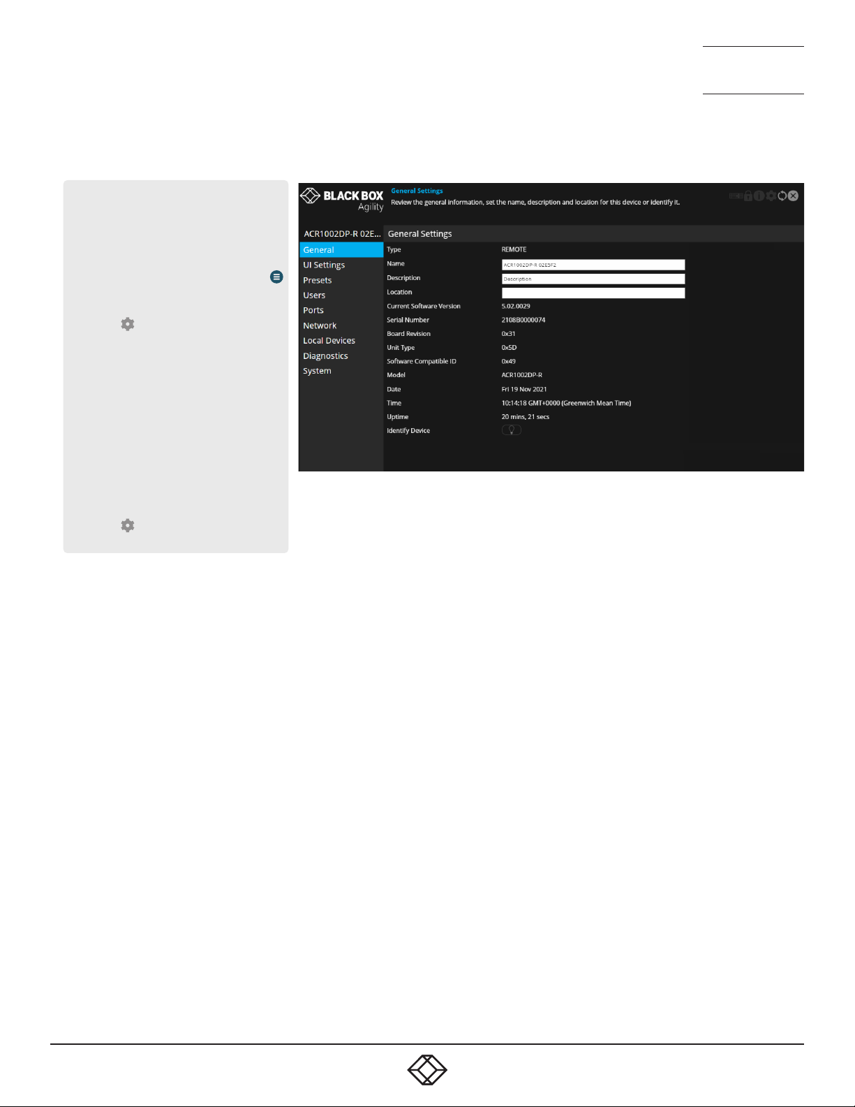
RECEIVER - GENERAL INFORMATION
To get here
You can access this page in two ways,
however, the rst method is not available if
the module is under iPATH control:
1 On the console keyboard attached to
the receiver, access the OSD by pressing
CTRL + ALT + C or tap the touchscreen
icon. The Preset Selection page will be
displayed.
2 Click the icon in the top right corner.
3 If necessary, click the General link.
OR
1 Connect a computer to the same network
as the receiver.
2 Run a web browser and enter the
IP address of the receiver:
https://169.254.1.32 (this is the default
address when using port 1). If you
are using SFP port 2, then the default
address will be https://169.254.1.42
Note: These default addresses can be
changed.
3 Click the icon in the top right corner.
4 If necessary, click the General link.
NEED HELP?
NEED HELP?
LEAVE T HE TECH TO U S
LEAVE T HE TECH TO U S
LIVE 24/7
LIVE 24/7
TECHNICAL
TECHNICAL
SUPPORT
SUPPORT
1.877.877.2269
1.877.877.2269
General Information
Type - States whether the device is a transmitter (TX) or a receiver
(RX).
Name - Name details that you can alter to distinguish this unit from all
others. Not shown when operating under iPATH server control.
Description - Allows you to optionally add a description of the device.
Useful when many Agility units are being used. Not shown when
operating under iPATH server control.
Location - Allows you to optionally add a description of the device’s
location. Useful when many Agility units are being used. Not shown
when operating under iPATH server control.
Current Software Version - Displays the version number of the
currently installed (and active) internal software.
Serial Number - Displays the xed serial number of the device.
Board Revision - Displays the revision number of the device’s main
circuit board.
Unit Type - Used for technical support purposes, this entry shows a code
depicting the type of the main circuit board.
Software Compatible ID - Used for technical support purposes, this entry
shows the software compatible ID of the main circuit board.
Model - Displays the model number of the device.
Date and Time - Displays the current date and time used by the device
when this page was last loaded (select refresh icon to update).
Uptime - Shows the time period for which the device has currently being
running since the last time this page was loaded (select refresh icon to
update).
Identify Device - When clicked, this button will cause the indicator on
the front panel of the device to flash to assist with identication when
multiple units are installed in the same area. A popup dialog will also be
displayed on screen showing all relevant identication details. Click the
Cancel button to stop the identication process or click the OK button to
close the popup (and then click the Identify Device button when you’re
ready to cancel this operation).
34
34
1. 8 7 7. 8 7 7. 2 2 69 BLACKBOX.COM
1. 8 7 7. 8 7 7. 2 2 69 BLACKBOX.COM
Page 35
RECEIVER - UI SETTINGS
To get here
You can access this page in two ways,
however, the rst method is not available if
the module is under iPATH control:
1 On the console keyboard attached to
the receiver, access the OSD by pressing
CTRL + ALT + C or tap the touchscreen
icon. The Preset Selection page will be
displayed.
2 Click the icon in the top right corner.
3 If necessary, click the UI Settings link.
OR
1 Connect a computer to the same network
as the receiver.
2 Run a web browser and enter the
IP address of the receiver:
https://169.254.1.32 (this is the default
address when using port 1). If you
are using SFP port 2, then the default
address will be https://169.254.1.42
Note: These default addresses can be
changed.
3 Click the icon in the top right corner.
4 If necessary, click the UI Settings link.
NEED HELP?
NEED HELP?
LEAVE T HE TECH TO U S
LEAVE T HE TECH TO U S
LIVE 24/7
LIVE 24/7
TECHNICAL
TECHNICAL
SUPPORT
SUPPORT
1.877.877.2269
1.877.877.2269
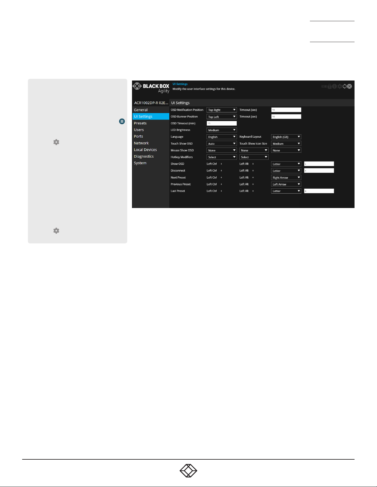
UI Settings
OSD Notication Position (plus Timeout) - Determines the location and
persistence of notications issued on users’ screens.
OSD Banner Position (plus Timeout) - Determines the location and
persistence of banners (a banner is a popup showing the current
preset/channel name) displayed on users’ screens.
OSD Timeout - Determines the persistence of the OSD if no interaction
has taken place.
LED brightness - Determines the brightness of the front and rear panel
LED indicators.
The following entries are also displayed when the unit is not under
iPATH control:
Language - Determines the language used for all text labels within the
conguration pages.*
Keyboard Layout - Determines the appropriate keyboard layout for use
with the conguration pages.*
* These entries are all visible but are not configurable under iPATH
control.
Touch Show OSD - (When touch screens are used) Determines whether
the Show OSD icon is displayed continually, not at all or automatically.*
Touch Show Icon Size - (When touch screens are used) Determines the
size of the Show OSD icon. Options range from Small to Very Large.*
Mouse Show OSD - Determines the mouse button press combination that
should be used to call the OSD.
Hotkey Modiers - Determines the special modier keys that will be used
to form the basis of all the hotkey functions listed below.
Show OSD... ...Last Preset - These entries determine the hotkey letters
required (together with the modier keys selected above) to enact various
presets and modes. Not shown when operating under iPATH server
control.
1. 8 7 7. 8 7 7. 2 2 69 BLACKBOX.COM
1. 8 7 7. 8 7 7. 2 2 69 BLACKBOX.COM
35
35
Page 36
RECEIVER - PRESETS
To get here
You can access this page in two ways, however, the rst method
is not available if the module is under iPATH control:
1 On the console keyboard attached to the receiver, access the
OSD by pressing CTRL + ALT + C or tap the touchscreen
icon. The Preset Selection page will be displayed.
2 Click the icon in the top right corner.
3 If necessary, click the Presets link.
4 Either add a new preset (click +) or click to edit an existing
one.
OR
1 Connect a computer to the same network as the receiver.
2 Run a web browser and enter the
IP address of the receiver:
https://169.254.1.32 (this is the default address when using
port 1). If you are using SFP port 2, then the default address
will be https://169.254.1.42 Note: These default addresses
can be changed.
3 Click the icon in the top right corner.
4 If necessary, click the Presets link.
5 Either add a new preset (click +) or click to edit an existing
one.
NEED HELP?
NEED HELP?
LEAVE T HE TECH TO U S
LEAVE T HE TECH TO U S
LIVE 24/7
LIVE 24/7
TECHNICAL
TECHNICAL
SUPPORT
SUPPORT
1.877.877.2269
1.877.877.2269
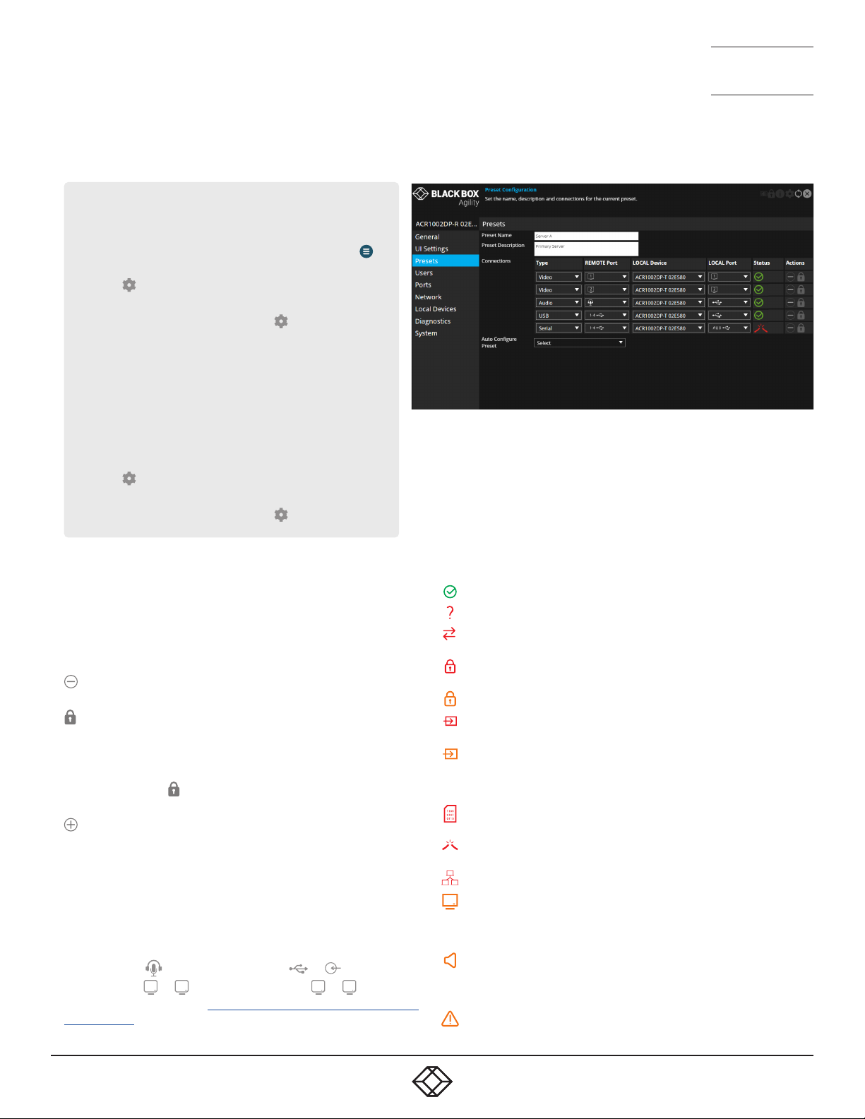
Preset Information
This page lists the details and connection status for the current
channel/preset which the receiver is using. Under iPATH control this
lists the connection details for the channel that the receiver is currently
connected to.
Each row details one type of connection which has been made. It lists the
output port on the receiver and the source port from the transmitter which
it is connected to, as well as the name of the device it is connected to.
Click this icon in the Actions column to remove a particular row of
connections from the list.
Click this icon to manually set the password for the specied
device so that it has the necessary permission to access
the appropriate channel on the selected transmitter. In most
connections, the access passwords for all the peripherals will be
set collectively during the initial linking between the receiver and
transmitter. The links given here provide an alternative method
as backup.
Click this icon to add a new connection to the list.
Auto Congure Preset - Select to automatically create a new set of
connection presets from the selected transmitter.
Analog and digital audio
ACR1002 units support both analog and digital audio connections from
the host PC. Although originating from possibly the same audio source,
these two audio types are switched completely separately and cannot
be mixed. In the connections table, the two types are represented thus:
• Analog audio ( ) at RX only connects to ( or ) at TX.
• Digital audio (1 or 2) at RX only connect to (1 or 2) at TX.
For more details, please see Appendix B - Support for analog and
digital audio.
Status
The following icons may be shown within the Status column:
The connection is fully operational.
A connection has not been established.
The control protocol version is incompatible/unsupported between
the peer and this device.
The control protocol security settings are incompatible/unsupported
between the peer and this device.
The connection failed the authorisation stage (most likely a bad password).
The connection is established but there is no input signal being
received from the peer device.
The connection has an invalid or unsupported input source signal
peer device (audio and video connections only), or the connection is
currently out of resources at the peer device, or there is insufcient
network bandwidth to support the requested data for this connection.
The encoding of the source data at the peer has stopped (due to an
error or fault).
There is no output device available on the port for this connection
(e.g., no monitor connected).
There is no data currently being received by the device.
The video data for the connection produces an output signal that
is out of range for the capabilities of this device, or the appliance
connected to this device, or the device is currently out of resources to
process the video data for this connection.
The audio data for the connection produces an output signal that
is out of range for the capabilities of this device, or the appliance
connected to this device, or the device is currently out of resources to
process the audio data for this connection.
The decoding of the data at this device has stopped (due to an error
or fault).
36
36
1. 8 7 7. 8 7 7. 2 2 69 BLACKBOX.COM
1. 8 7 7. 8 7 7. 2 2 69 BLACKBOX.COM
Page 37
RECEIVER - USERS
To get here
You can access this page in two ways,
however, the rst method is not available if
the module is under iPATH control:
1 On the console keyboard attached to
the receiver, access the OSD by pressing
CTRL + ALT + C or tap the touchscreen
icon. The Preset Selection page will be
displayed.
2 Click the icon in the top right corner.
3 If necessary, click the Users link.
OR
1 Connect a computer to the same network
as the receiver.
2 Run a web browser and enter the
IP address of the receiver:
https://169.254.1.32 (this is the default
address when using port 1). If you
are using SFP port 2, then the default
address will be https://169.254.1.42
Note: These default addresses can be
changed.
3 Click the icon in the top right corner.
4 If necessary, click the Users link.
NEED HELP?
NEED HELP?
LEAVE T HE TECH TO U S
LEAVE T HE TECH TO U S
LIVE 24/7
LIVE 24/7
TECHNICAL
TECHNICAL
SUPPORT
SUPPORT
1.877.877.2269
1.877.877.2269
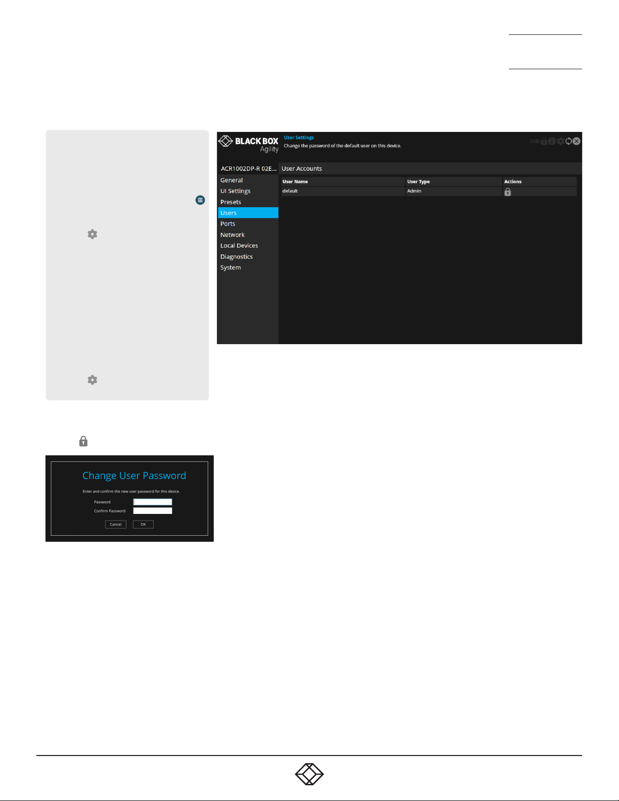
User accounts
This page allows you to change the password for the admin user.
Click the icon to display the following dialog:
Enter and conrm the current and new admin password and click OK.
1. 8 7 7. 8 7 7. 2 2 69 BLACKBOX.COM
1. 8 7 7. 8 7 7. 2 2 69 BLACKBOX.COM
37
37
Page 38
RECEIVER - PORTS
To get here
You can access this page in two ways,
however, the rst method is not available if
the module is under iPATH control:
1 On the console keyboard attached to
the receiver, access the OSD by pressing
CTRL + ALT + C or tap the touchscreen
icon. The Preset Selection page will be
displayed.
2 Click the icon in the top right corner.
3 If necessary, click the Ports link.
OR
1 Connect a computer to the same network
as the receiver.
2 Run a web browser and enter the
IP address of the receiver:
https://169.254.1.32 (this is the default
address when using port 1). If you
are using SFP port 2, then the default
address will be https://169.254.1.42
Note: These default addresses can be
changed.
3 Click the icon in the top right corner.
4 If necessary, click the Ports link.
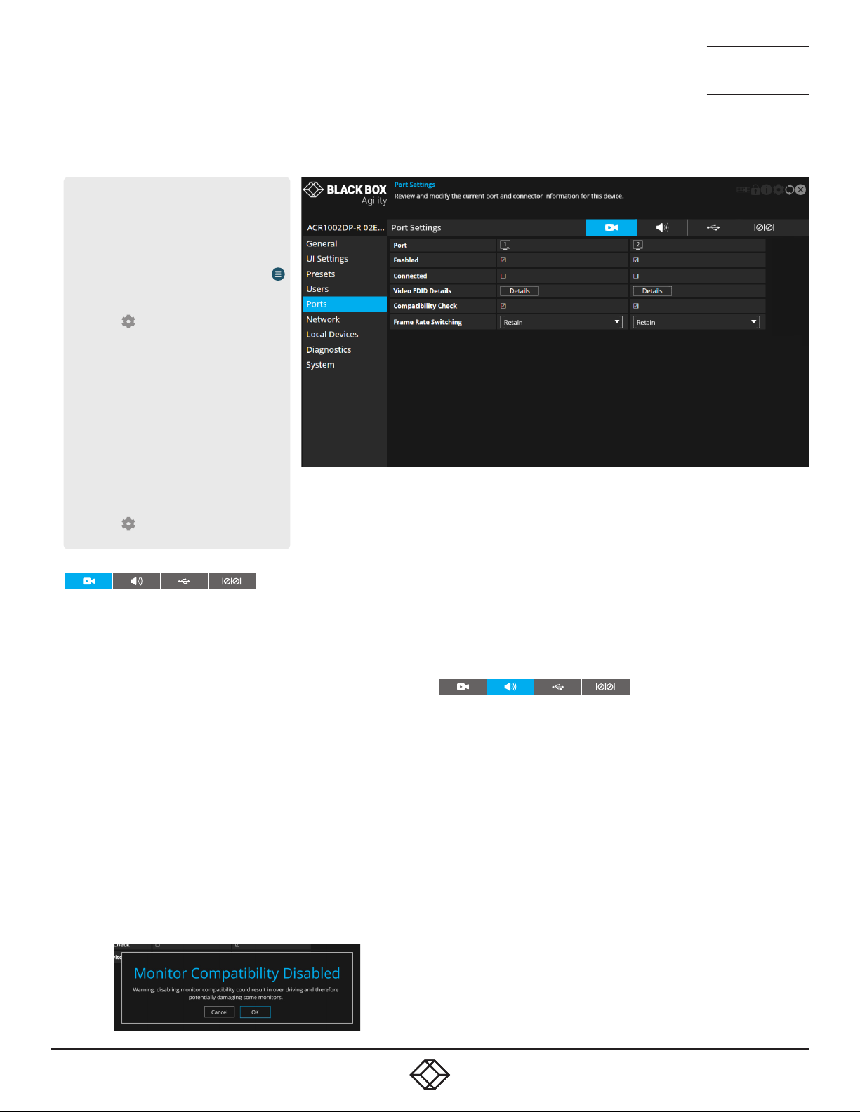
Video Ports
This page provides basic information about the two video ports located
on the receiver.
Enabled - Conrms whether each video port is enabled or disabled.
Connected - Conrms whether functioning video displays are
connected to the two video ports.
Video EDID Details - Click the Details button to show a popup for the
connected video display. EDID details listed include: Manufacturer,
model, serial number, manufacture date, EDID version as well as
supported (and preferred) EDID modes, maximum bits per color,
encodings, colourimetry and dynamic range masterings supported
by the monitor. Note: EDID modes that are supported by the monitor
but not by the device will be greyed out. In cases where a resolution
reported by the video display is supported, but at a lower frame rate
than the display calls for, such entries will be shown in italics.
Compatibility Check - WARNING: Disabling this option can result in
damage to display monitors in certain circumstances. When ticked this
option conrms video compatibility between the source and display
device, (such as the video display’s maximum resolution, bpc, etc.) and
prevents signals being sent that the video display can’t support. When
unticked, signals will always be sent regardless of video display’s
declared capabilities. If you untick the option, the following warning
will be displayed:
NEED HELP?
NEED HELP?
LEAVE T HE TECH TO U S
LEAVE T HE TECH TO U S
LIVE 24/7
LIVE 24/7
TECHNICAL
TECHNICAL
SUPPORT
SUPPORT
1.877.877.2269
1.877.877.2269
Frame Rate Switching - Determines the strategy to use for the frame rate
when switching resolutions. Similar in function to the Match Frame Rate
setting on iPATH servers:
Force 60 - The frame rate is always forced to be 60Hz unless the
Compatibility check option is on and the monitor does not indicate it
supports 60Hz.
Retain - When switching to the same resolution with a potentially
different frame rate, it will retain the current frame.
Auto - The frame rate always changes to match the mode it is connected to.
Audio Ports
This page provides basic information about the analog and digital audio
ports located on the receiver.
Enabled - Conrms whether the audio ports are enabled or disabled.
Connected - Conrms whether devices are connected to respective ports.
Gain - (Analog audio only) Determines the microphone amplication level:
None - no device connected on this port.
Mic - standard gain for normal microphone input devices.
Mic boost - 20dB boost to volume for microphone input devices.
Audio EDID Details - Click the Details button to show a popup listing
the audio capabilities of the device connected to that video port.
Unsupported formats will be greyed out.
Compatibility Check - If unticked, audio will be output regardless of the
attached device’s capabilities, however, if ticked the RX will not output
audio on this port if it is not compatible with the attached device’s audio
capabilities. For example, if an attached device supports 2 channel stereo
but the incoming stream is 6 channels, turning this off may allow L & R
audio output to work - if the attached device can cope, but other channels
will be lost (ie, there is no down-mix support).
38
38
1. 8 7 7. 8 7 7. 2 2 69 BLACKBOX.COM
1. 8 7 7. 8 7 7. 2 2 69 BLACKBOX.COM
Page 39

NEED HELP?
NEED HELP?
LEAVE T HE TECH TO U S
LEAVE T HE TECH TO U S
LIVE 24/7
LIVE 24/7
TECHNICAL
TECHNICAL
SUPPORT
SUPPORT
1.877.877.2269
1.877.877.2269
USB Ports
This page provides basic information about the USB ports numbered 1
to 4 inclusive, located on the receiver.
Type - Identies the type of USB ports. All are listed as Emulated.
Enabled - Conrms whether the USB ports are enabled or disabled.
HID Only - When ticked, all ports are limited to supporting Human
Interface Devices only, such as keyboards and mice.
Disable Mass Storage - When ticked, this option prevents the use of
USB mass storage devices on the receiver unit. This could be useful
in situations where smart card readers need to be used for security
purposes but the use of USB drives need to be prevented.
Security - Controls whether USB data is encrypted. On forces always
on, Off forces always off and Prefer off will be off unless the transmitter
requests it.
USB Port Mapping and Reservations - This section is useful when
multiple touchscreens are in use and allows you to match each USB
port input to the correct touchscreen.
Connected Devices - This section lists all connected devices with
manufacturer and model details where reported. Click the Details
button against each device to view further information, such as the
Device Type, Protocol Version, Speed and Max Power Consumption.
Serial Port
This page provides basic information about the serial option port located
on the RX unit.
Port - Indicates that an optional USB-to-serial converter may be
connected to ports 1 - 4 of the receiver (a similar device needs to also be
connected to the AUX port on the transmitter).
Enabled - Conrms whether the serial port is enabled or disabled.
Disabling the serial port (or excluding it from the preset connection list)
allows an attached USB-serial adapter to instead be used over the USB
connection to the TX, rather than the explicit serial connection.
1. 8 7 7. 8 7 7. 2 2 69 BLACKBOX.COM
1. 8 7 7. 8 7 7. 2 2 69 BLACKBOX.COM
39
39
Page 40
RECEIVER - NETWORK
To get here
You can access this page in two ways,
however, the rst method is not available if
the module is under iPATH control:
1 On the console keyboard attached to
the receiver, access the OSD by pressing
CTRL + ALT + C or tap the touchscreen
icon. The Preset Selection page will be
displayed.
2 Click the icon in the top right corner.
3 If necessary, click the Network link.
OR
1 Connect a computer to the same network
as the receiver.
2 Run a web browser and enter the
IP address of the receiver:
https://169.254.1.32 (this is the default
address when using port 1). If you
are using SFP port 2, then the default
address will be https://169.254.1.42
Note: These default addresses can be
changed.
3 Click the icon in the top right corner.
4 If necessary, click the Network link.
NEED HELP?
NEED HELP?
LEAVE T HE TECH TO U S
LEAVE T HE TECH TO U S
LIVE 24/7
LIVE 24/7
TECHNICAL
TECHNICAL
SUPPORT
SUPPORT
1.877.877.2269
1.877.877.2269
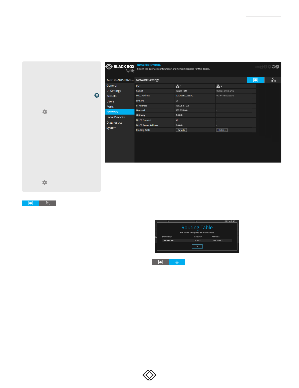
Port Settings
This page provides numerous network details for each of the installed
ports on the receiver.
Socket - Details each operational network socket and what connection
speeds they have established. Socket 2 is determined by the SFP
modules plugged into it.
MAC Address - Displays the unique, xed hardware identication
number for each port.
Link Up - Indicates whether the link state of this network interface is
up. This should be the case if the device is connected to a functioning
network.
IP Address - This shows the IP address in use, which can be obtained
via DHCP, a static IP or a link local (zero-cong).
Netmask - The netmask of this network interface. The device can
function in a network zero-cong state which does not require the
setting of a static netmask.
Gateway - The gateway address of this network interface. The device
can function in a network zero-cong state which does not require the
setting of a static gateway.
Static IP Address - When the ‘DHCP enabled’ option (below) is
unchecked, click on ‘Edit’ to enter/edit a static IP Address, Netmask
and Gateway for the unit.
DHCP Enabled - When ticked, the corresponding port will derive its IP
Address, Netmask and Gateway details from the DHCP server listed in
the eld below.
DHCP Server Address - Indicates the server that provided the DHCP
details.
Routing Table - Click on ‘Details’ to show the routing table entries
corresponding to this network interface. In it are the destination
address, gateway and netmask for the routes to particular
network destinations.
Network Information
Default Domain - Reserved for future use.
Independent Networks - When ticked, the Agility receiver will treat its two
main network ports as independent routes to the transmitter(s) and not
attempt to nd secondary cross connections, which may not be possible
due to the network topology. This setting will have no effect when Agility
receivers link with Agility transmitters due to their use of auto discovery.
However, when an Agility receiver links with other dual port Agility
transmitters, enabling this option can prevent unnecessary delays due to
the time taken looking for routes that are effectively network dead ends.
Route of Last Resort - In a multi-interface device such as this, the
interface which is ticked will be used as the default whenever it is unclear
which interface should be used for network trafc.
Dynamic DNS Servers - List of DNS server addresses obtained via DHCP.
Static DNS Servers - Lists DNS server addresses that have been manually
congured.
40
40
1. 8 7 7. 8 7 7. 2 2 69 BLACKBOX.COM
1. 8 7 7. 8 7 7. 2 2 69 BLACKBOX.COM
Page 41

NTP Enabled - When ticked, the unit will derive its time and date
information from a suitable NTP server.
NTP Key ID - The ID of the key used for secure NTP.
NTP Key Value - The value of the key used for secure NTP as a
hexadecimal string.
Dynamic NTP Servers - Lists NTP server addresses obtained via DHCP.
Static NTP Servers - Lists NTP server addresses that have been
manually congured.
iPATH Enabled - Indicates whether server management is enabled for
this device.
Dynamic iPATH Servers - Lists iPATH server addresses obtained via
DHCP.
Static iPATH Servers - Lists management server addresses that have
been manually congured.
NEED HELP?
NEED HELP?
LEAVE T HE TECH TO U S
LEAVE T HE TECH TO U S
LIVE 24/7
LIVE 24/7
TECHNICAL
TECHNICAL
SUPPORT
SUPPORT
1.877.877.2269
1.877.877.2269
1. 8 7 7. 8 7 7. 2 2 69 BLACKBOX.COM
1. 8 7 7. 8 7 7. 2 2 69 BLACKBOX.COM
41
41
Page 42

RECEIVER - LOCAL DEVICES
To get here
You can access this page in two ways,
however, the rst method is not available if
the module is under iPATH control:
1 On the console keyboard attached to
the receiver, access the OSD by pressing
CTRL + ALT + C or tap the touchscreen
icon. The Preset Selection page will be
displayed.
2 Click the icon in the top right corner.
3 If necessary, click the Local Devices link.
OR
1 Connect a computer to the same network
as the receiver.
2 Run a web browser and enter the
IP address of the receiver:
https://169.254.1.32 (this is the default
address when using port 1). If you
are using SFP port 2, then the default
address will be https://169.254.1.42
Note: These default addresses can be
changed.
3 Click the icon in the top right corner.
4 If necessary, click the Local Devices link.
NEED HELP?
NEED HELP?
LEAVE T HE TECH TO U S
LEAVE T HE TECH TO U S
LIVE 24/7
LIVE 24/7
TECHNICAL
TECHNICAL
SUPPORT
SUPPORT
1.877.877.2269
1.877.877.2269
Local Devices
This page lists the available transmitters on the network which aren’t
under iPATH control - Note: Older Agility units are generally not
discoverable using this process, however, if the Start of Life process
was able to connect point-to-point to an ACR1002DP then it will have
created a ‘static’ device entry and thus it will appear on this screen.
However, the cog and light bulb icons will not function for the entry.
In the Actions column you can perform the following functions for each
listed transmitter:
• Click to view the conguration page of the transmitter. When
clicked, you will be directed to the General page for the chosen
transmitter.
• Click to flash the front panel indicators on the transmitter to
assist with identication.
• Click the X button in the top right corner to return to return to the
receiver pages.
42
42
1. 8 7 7. 8 7 7. 2 2 69 BLACKBOX.COM
1. 8 7 7. 8 7 7. 2 2 69 BLACKBOX.COM
Page 43
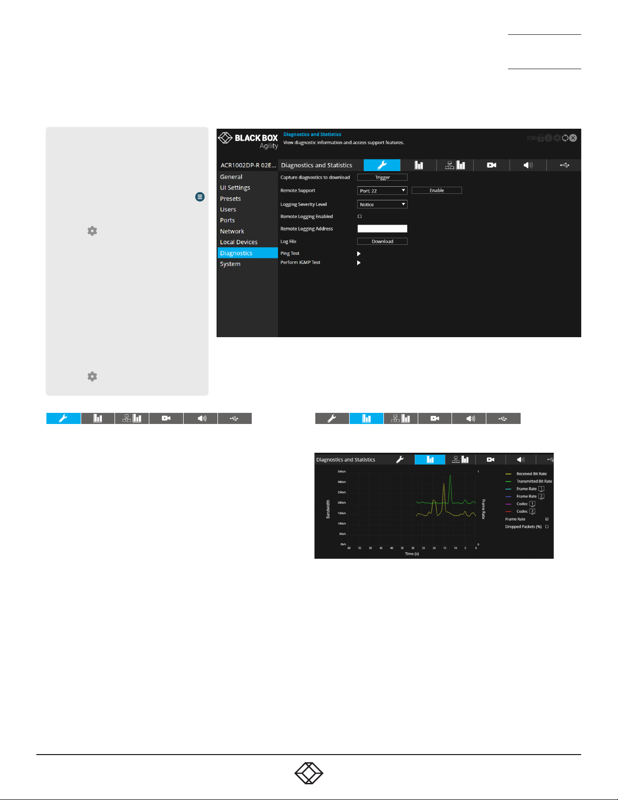
RECEIVER - DIAGNOSTICS AND STATISTICS
To get here
You can access this page in two ways,
however, the rst method is not available if
the module is under iPATH control:
1 On the console keyboard attached to
the receiver, access the OSD by pressing
CTRL + ALT + C or tap the touchscreen
icon. The Preset Selection page will be
displayed.
2 Click the icon in the top right corner.
3 If necessary, click the Diagnostics link.
OR
1 Connect a computer to the same network
as the receiver.
2 Run a web browser and enter the
IP address of the receiver:
https://169.254.1.32 (this is the default
address when using port 1). If you
are using SFP port 2, then the default
address will be https://169.254.1.42
Note: These default addresses can be
changed.
3 Click the icon in the top right corner.
4 If necessary, click the Diagnostics link.
NEED HELP?
NEED HELP?
LEAVE T HE TECH TO U S
LEAVE T HE TECH TO U S
LIVE 24/7
LIVE 24/7
TECHNICAL
TECHNICAL
SUPPORT
SUPPORT
1.877.877.2269
1.877.877.2269
Log Settings
This page provides numerous key diagnostic log settings.
Capture diagnostics to download - Request generation of a diagnostics
dump le. This will then be downloaded by the host computer’s
browser, this is an encrypted diagnostics le which can be used by
technical support to diagnose and x an issue. If using the local OSD,
then this will show ‘Capture diagnostics to USB’ and will download the
same le onto a USB memory stick inserted into USB ports 1-4. Note:
When in point to point mode, you will need to plug in a USB flash drive
and capture the logs to it.
Remote Support - When using the remote server, this option
determines which port will be used. Multiple options are offered in case
one or more ports are blocked by your rewall.
Logging Severity Level - Denes the level of messages that will be
logged (according to RFC5424). Level 5 (Notice: normal but signicant
condition) is the default setting; Agility supports levels 1 to 7. Choosing
levels 6 (Informational) or 7 (Debug) will cause larger numbers of
lesser events to also be logged, with a potential impact to overall
performance. These levels should only be used if working with the
support team to diagnose a specic issue.
Remote Logging Enabled - Tick to send log les to the chosen Remote
Logging Address.
Remote Logging Address - Enter a valid IP address for a syslog server
on the local network where status logs can be sent.
Log File - If viewing this page using a browser: Click to download the log
le to the host computer’s browser. If viewing this page via the OSD, the
log will be shown as a scrollable list.
Ping Test - Allows you to conduct a ping test to any selected address or
device.
Perform IGMP Test - Allows you to conduct an IGMP test on connected
devices, selectable from the drop-down list.
Basic Graph
This page shows a real time graph with the following entries:
• Received and Transmitted Bit Rates - the values of these correspond to
the bandwidth axis on the left.
• Frame Rate - for both heads. Values are labeled when they change and
correspond to the axis on the right.
• Codec - for both heads. These represent the compression used: 1 is
better than 4.
• Dropped Packets - for both heads. Values are labeled when they change
and correspond to the axis on the right.
Note: Use the Frame Rate and Dropped Packets tick box options to
determine which is displayed at any given time.
1. 8 7 7. 8 7 7. 2 2 69 BLACKBOX.COM
1. 8 7 7. 8 7 7. 2 2 69 BLACKBOX.COM
43
43
Page 44

Network Statistics
This page allows you to view current communication statistics
and also to create graphs in real time.
Capture and Graph Statistics - When ticked, the page will create
a real time graph plotting Received Bytes alongside Received
Packets.
After Capture and Graph Statistics is enabled, the Show Legend
checkbox will show all other items that can be included on the
plot. Click an item to tick and include it.
Video Port Status and Statistics
This page provides wide ranging information for support
purposes.
Audio Port Status and Statistics
This page provides wide ranging information for support
purposes.
NEED HELP?
NEED HELP?
LEAVE T HE TECH TO U S
LEAVE T HE TECH TO U S
LIVE 24/7
LIVE 24/7
TECHNICAL
TECHNICAL
SUPPORT
SUPPORT
1.877.877.2269
1.877.877.2269
USB Port Status and Statistics
Not yet implemented.
44
44
1. 8 7 7. 8 7 7. 2 2 69 BLACKBOX.COM
1. 8 7 7. 8 7 7. 2 2 69 BLACKBOX.COM
Page 45
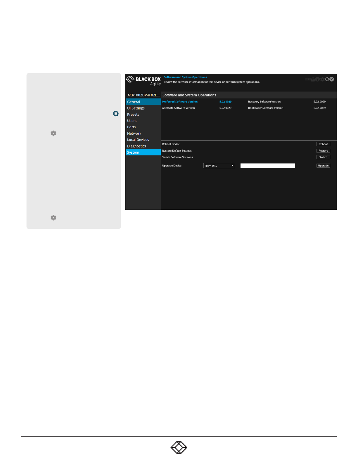
RECEIVER - SYSTEM
To get here
You can access this page in two ways,
however, the rst method is not available if
the module is under iPATH control:
1 On the console keyboard attached to
the receiver, access the OSD by pressing
CTRL + ALT + C or tap the touchscreen
icon. The Preset Selection page will be
displayed.
2 Click the icon in the top right corner.
3 If necessary, click the System link.
OR
1 Connect a computer to the same network
as the receiver.
2 Run a web browser and enter the
IP address of the receiver:
https://169.254.1.32 (this is the default
address when using port 1). If you
are using SFP port 2, then the default
address will be https://169.254.1.42
Note: These default addresses can be
changed.
3 Click the icon in the top right corner.
4 If necessary, click the System link.
NEED HELP?
NEED HELP?
LEAVE T HE TECH TO U S
LEAVE T HE TECH TO U S
LIVE 24/7
LIVE 24/7
TECHNICAL
TECHNICAL
SUPPORT
SUPPORT
1.877.877.2269
1.877.877.2269
Software and System Operations
This page contains various indications and options related to the
internal software of the unit.
Note: The highlighted (and colored) entry is the version of software
currently running.
Preferred Software Version - The software version the device will boot
into upon a reboot.
Recovery Software Version - The software version the device will boot
into if placed into recovery mode.
Alternate Software Version - The other (backup) version of software
the device has available.
Reboot Device - Click the Reboot button to Reboot the device.
Restore Default Settings - Click the Restore button to restore the
device to factory default settings.
Switch Software Versions - Click to switch to the listed ‘Alternative
Software Version’.
Upgrade Device - If viewing this page using a browser: Allows you to
upgrade the rmware either from a trusted URL or from a locally stored
le. Use the eld to dene the source and then click the Upgrade
button.
1. 8 7 7. 8 7 7. 2 2 69 BLACKBOX.COM
1. 8 7 7. 8 7 7. 2 2 69 BLACKBOX.COM
45
45
Page 46
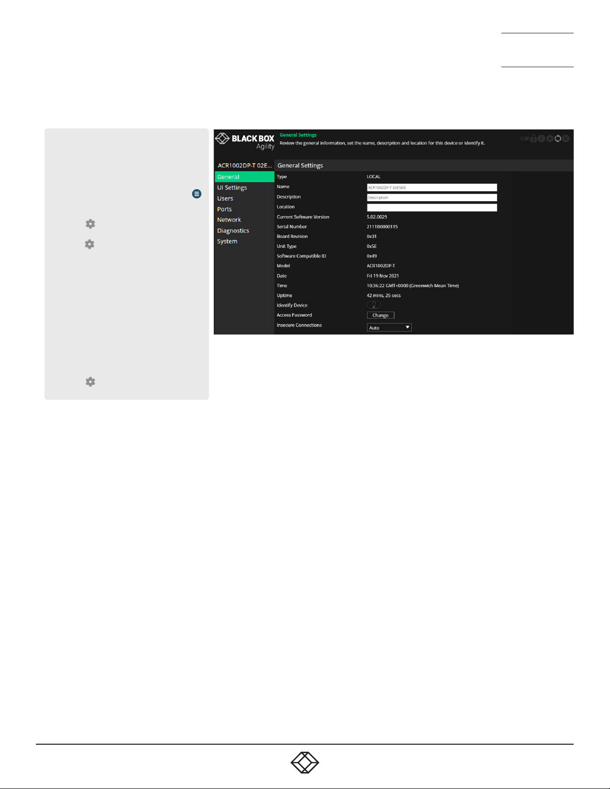
TRANSMITTER - GENERAL INFORMATION
To get here
You can access this page in two ways,
however, the rst method is not available if
the module is under iPATH control:
1 On the console keyboard attached to
the receiver, access the OSD by pressing
CTRL + ALT + C or tap the touchscreen
icon. The Preset Selection page will be
displayed.
2 Click the icon in the top right corner.
3 Click the Local Devices option and then
click the icon for the required
transmitter.
4 If necessary, click the General link.
OR
1 Connect a computer to the same network
as the transmitter.
2 Run a web browser and enter the IP address
of the transmitter: https://169.254.1.33
(this is the default address when
using port 1). If you are using SFP
port 2, then the default address will be
https://169.254.1.43 Note: These default
addresses can be changed.
3 Click the icon in the top right corner.
4 If necessary, click the General link.
NEED HELP?
NEED HELP?
LEAVE T HE TECH TO U S
LEAVE T HE TECH TO U S
LIVE 24/7
LIVE 24/7
TECHNICAL
TECHNICAL
SUPPORT
SUPPORT
1.877.877.2269
1.877.877.2269
General Information
Type - States whether the device is a transmitter (TX) or a receiver
(RX).
Name - Name details that you can alter to distinguish this unit from all
others. Not shown when operating under iPATH server control.
Description - Allows you to optionally add a description of the device.
Useful when many Agility units are being used. Not shown when
operating under iPATH server control.
Location - Allows you to optionally add a description of the device’s
location. Useful when many Agility units are being used. Not shown
when operating under iPATH server control.
Current Software Version - Displays the version number of the
currently installed and running internal software (unit can have two
different software versions installed at once).
Serial Number - Displays the xed serial number of the device.
Board Revision - Displays the revision number of the device’s main
circuit board.
Unit Type - Used for technical support purposes, this entry shows a
code depicting the type of the main circuit board.
Software Compatible ID - Used for technical support purposes, this
entry shows the software compatible ID of the main circuit board.
Model - Displays the model number of the device.
Date and Time - Displays the current date and time used by the device
when this page was last loaded (select refresh icon to update).
Uptime - Shows the time period for which the device has currently being
running since the last time this page was loaded (select refresh icon to
update).
Identify Device - When clicked, this button will cause the indicator on
the front panel of the device to flash to assist with identication when
multiple units are installed in the same area. A popup dialog will also be
displayed on screen showing all relevant identication details. Click the
Cancel button to stop the identication process or click the OK button to
close the popup (and then click the Identify Device button when you’re
ready to cancel this operation).
Access Password - Sets the password that a receiver must provide in
order to connect (video, audio, etc.) to the transmitter
Insecure Connections - Controls whether the transmitter will accept
insecure connections from receivers. Insecure connections are those
from older Agility products where the security credentials are not
implemented. Initially, the transmitter will default to ‘auto’ which allows
it to decide the setting based on the type of device that rst connects
to it. Once a device has connected, the setting will be changed to either
‘Allowed’ or ‘Disallowed’.
46
46
1. 8 7 7. 8 7 7. 2 2 69 BLACKBOX.COM
1. 8 7 7. 8 7 7. 2 2 69 BLACKBOX.COM
Page 47
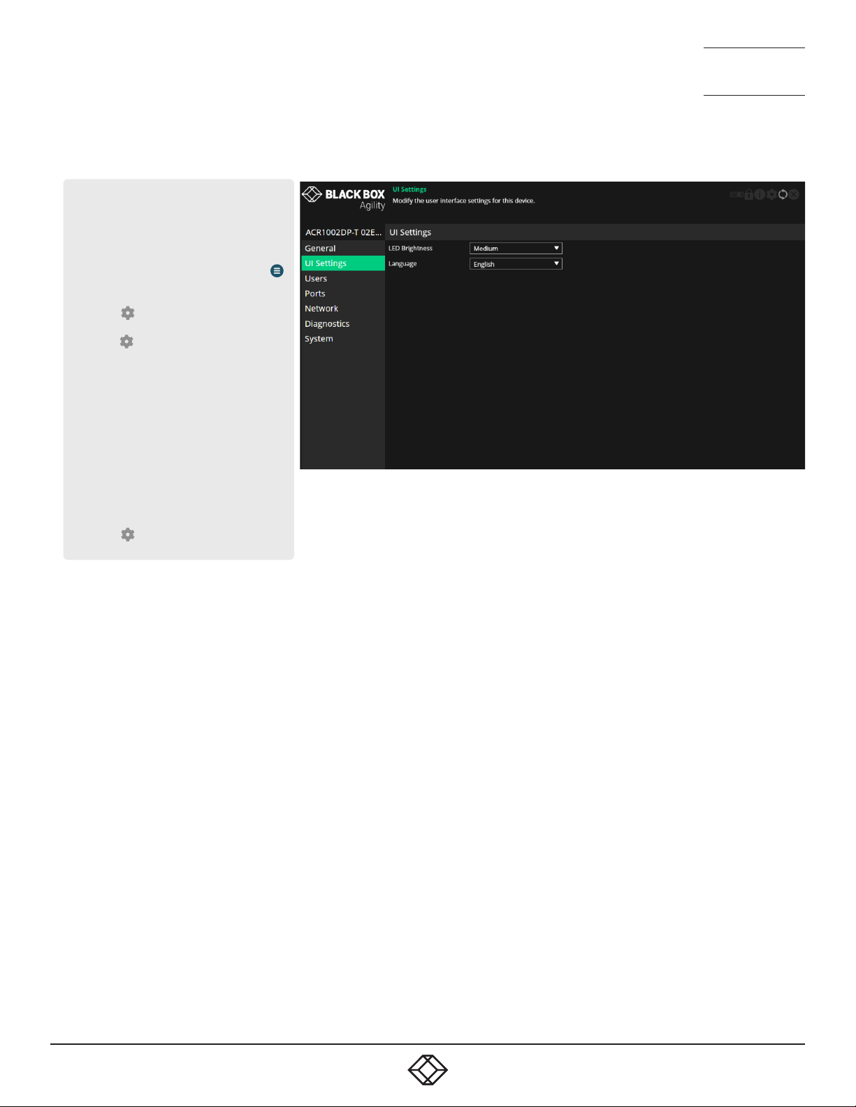
TRANSMITTER - UI SETTINGS
To get here
You can access this page in two ways,
however, the rst method is not available if
the module is under iPATH control:
1 On the console keyboard attached to
the receiver, access the OSD by pressing
CTRL + ALT + C or tap the touchscreen
icon. The Preset Selection page will be
displayed.
2 Click the icon in the top right corner.
3 Click the Local Devices option and then
click the icon for the required
transmitter.
4 If necessary, click the UI Settings link.
OR
1 Connect a computer to the same network
as the transmitter.
2 Run a web browser and enter the IP address
of the transmitter: https://169.254.1.33
(this is the default address when
using port 1). If you are using SFP
port 2, then the default address will be
https://169.254.1.43 Note: These default
addresses can be changed.
3 Click the icon in the top right corner.
4 If necessary, click the UI Settings link.
NEED HELP?
NEED HELP?
LEAVE T HE TECH TO U S
LEAVE T HE TECH TO U S
LIVE 24/7
LIVE 24/7
TECHNICAL
TECHNICAL
SUPPORT
SUPPORT
1.877.877.2269
1.877.877.2269
UI Settings
LED brightness - Determines the brightness of the front and rear panel
LED indicators.
Language - Determines the language used for all text labels within the
conguration pages.
1. 8 7 7. 8 7 7. 2 2 69 BLACKBOX.COM
1. 8 7 7. 8 7 7. 2 2 69 BLACKBOX.COM
47
47
Page 48
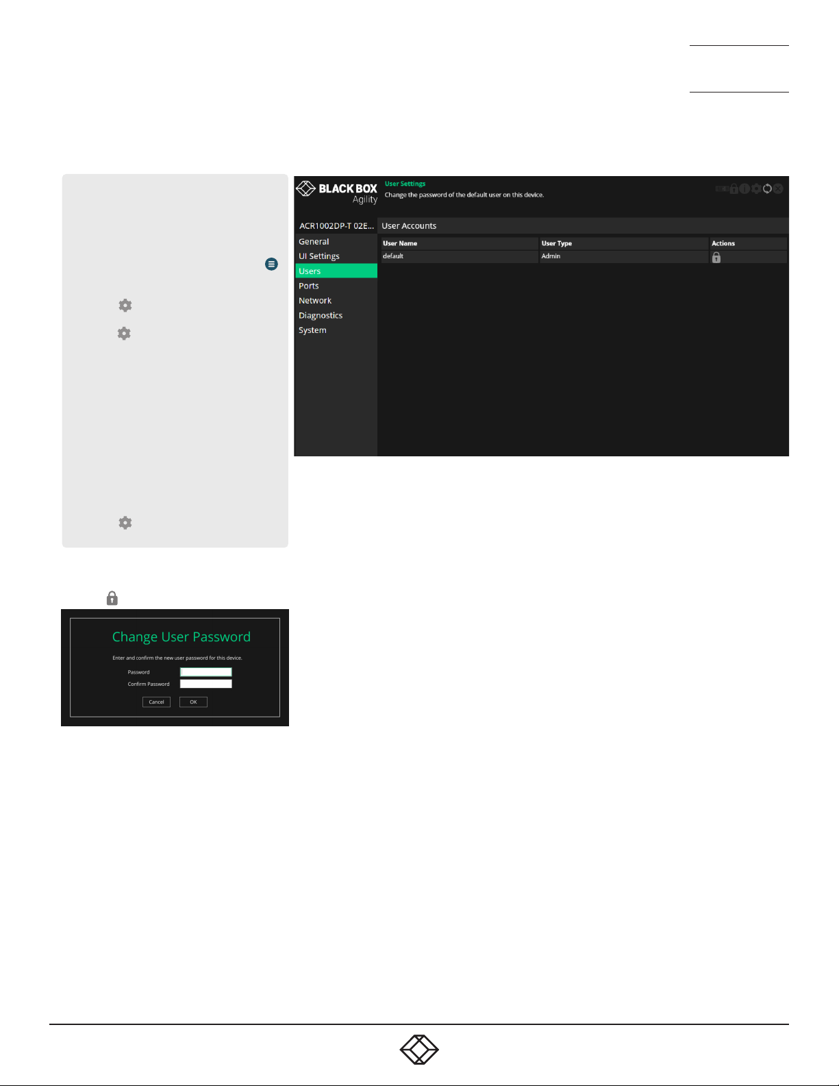
TRANSMITTER - USERS
To get here
You can access this page in two ways,
however, the rst method is not available if
the module is under iPATH control:
1 On the console keyboard attached to
the receiver, access the OSD by pressing
CTRL + ALT + C or tap the touchscreen
icon. The Preset Selection page will be
displayed.
2 Click the icon in the top right corner.
3 Click the Local Devices option and then
click the icon for the required
transmitter.
4 If necessary, click the Users link.
OR
1 Connect a computer to the same network
as the transmitter.
2 Run a web browser and enter the IP address
of the transmitter: https://169.254.1.33
(this is the default address when
using port 1). If you are using SFP
port 2, then the default address will be
https://169.254.1.43 Note: These default
addresses can be changed.
3 Click the icon in the top right corner.
4 If necessary, click the Users link.
NEED HELP?
NEED HELP?
LEAVE T HE TECH TO U S
LEAVE T HE TECH TO U S
LIVE 24/7
LIVE 24/7
TECHNICAL
TECHNICAL
SUPPORT
SUPPORT
1.877.877.2269
1.877.877.2269
User accounts
This page allows you to change the password for the admin user.
Click the icon to display the following dialog:
Enter and conrm the current and new admin password and click OK.
48
48
1. 8 7 7. 8 7 7. 2 2 69 BLACKBOX.COM
1. 8 7 7. 8 7 7. 2 2 69 BLACKBOX.COM
Page 49
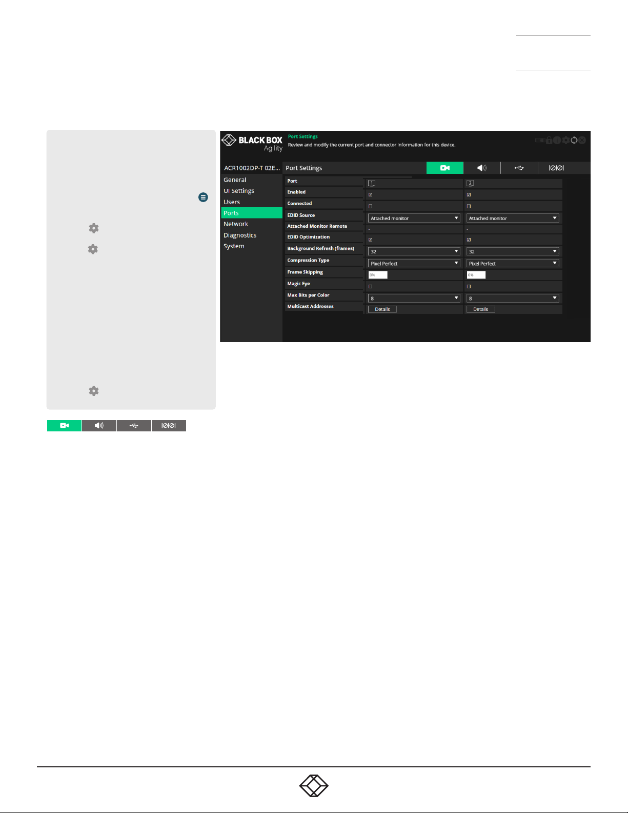
TRANSMITTER - PORTS
To get here
You can access this page in two ways,
however, the rst method is not available if
the module is under iPATH control:
1 On the console keyboard attached to
the receiver, access the OSD by pressing
CTRL + ALT + C or tap the touchscreen
icon. The Preset Selection page will be
displayed.
2 Click the icon in the top right corner.
3 Click the Local Devices option and then
click the icon for the required
transmitter.
4 If necessary, click the Ports link.
OR
1 Connect a computer to the same network
as the transmitter.
2 Run a web browser and enter the IP address
of the transmitter: https://169.254.1.33
(this is the default address when
using port 1). If you are using SFP
port 2, then the default address will be
https://169.254.1.43 Note: These default
addresses can be changed.
3 Click the icon in the top right corner.
4 If necessary, click the Ports link.
NEED HELP?
NEED HELP?
LEAVE T HE TECH TO U S
LEAVE T HE TECH TO U S
LIVE 24/7
LIVE 24/7
TECHNICAL
TECHNICAL
SUPPORT
SUPPORT
1.877.877.2269
1.877.877.2269
Video Ports
This page provides basic information about the two video ports located
on the transmitter.
Enabled - Conrms whether each video port is enabled or disabled.
Connected - Conrms whether functioning host video drivers are
connected to the two video ports.
EDID Source - Lists the EDID mode currently being output on the two
video connectors. .
Attached Monitor Receiver - If the ‘Attached monitor’ option has been
selected as the ‘EDID Source’, then this displays the name of the
receiver that supplied the EDID currently being used.
EDID Optimization - When ticked, and if the EDID source option is
set to ‘Attached monitor’; upon connecting with a new receiver, the
transmitter will compare the preferred video mode of the new monitor
with the current video output from the host PC. Only if they differ will
the transmitter present the new monitor’s EDID to the host PC. This
option speeds up switching as the host PCs graphics card does not
have to go through a hotplug detect routine each time a new receiver
is connected. If this setting is unticked, the transmitter will always
present a new EDID to the host PC.
Background Refresh (frames) - The system will send all changing
video as soon as it changes. In addition, it is possible to send
unchanging video in the background, to overcome problems of lost
network trafc. This control will congure how often a whole frame of
video will be sent alongside changing video. In situations of frequently
changing video, or high reliability networks, this value can be set to a
higher number, or even set to disabled.
Compression Type - Allows you to select the compression method to best
suit the nature of the video sources. Settings are: Pixel Perfect, Adaptive,
Smoothest Video or Advanced (which allows you to set the maximum and
minimum compression levels).
Frame Skipping - Frame Skipping involves ‘missing out’ video frames
between those captured by the transmitter. For video sources that update
only infrequently or for those that update very frequently but where high
delity is not required, frame skipping is a good strategy for reducing the
overall bandwidth consumed by the system. Range: 0 to 100%.
Magic Eye - When ticked, this feature increases performance and reduces
network trafc if Agility units are used with host computers that have
dithered video output. It also improves performance if the video source is
noisy.
Max Bits per Pixel - These settings are xed at 24bpp (ie, 8bpc) for this
model.
Multicast Addresses - This section lists all video multicast IP addresses
that have been congured. Setting the eld to a blank (empty string)
value will cause the system to automatically generate a default multicast
address.
1. 8 7 7. 8 7 7. 2 2 69 BLACKBOX.COM
1. 8 7 7. 8 7 7. 2 2 69 BLACKBOX.COM
49
49
Page 50

NEED HELP?
NEED HELP?
LEAVE T HE TECH TO U S
LEAVE T HE TECH TO U S
LIVE 24/7
LIVE 24/7
TECHNICAL
TECHNICAL
SUPPORT
SUPPORT
1.877.877.2269
1.877.877.2269
Audio Ports
This page provides basic information about the audio ports located on
the TX unit.
Enabled - Conrms whether the audio ports are enabled or disabled.
Connected - Conrms whether devices are connected to respective
ports.
EDID Source - Determines which audio EDID should be used:
Attached Monitor - use the audio capabilities reported by the monitor.
None - remove audio support from the EDID presented by the TX to the
connected PC.
2-Channel - apply a generic stereo audio EDID.
Attached Monitor Receiver - If the EDID source option is set to
‘Attached monitor’, then this displays the name of the RX device that
supplied the EDID currently being used.
EDID Optimization - When ticked, and if the EDID source option is
set to ‘Attached monitor’; upon connecting with a new receiver, the
transmitter will compare the preferred audio mode of the new monitor
with the current audio output from the host PC. Only if they differ will
the transmitter present the new monitor’s EDID to the host PC. This
option speeds up switching as the host PCs graphics card does not
have to go through a hotplug detect routine each time a new receiver
is connected. If this setting is unticked, the transmitter will always
present a new EDID to the host PC.
Multicast Addresses - This section lists all audio multicast IP
addresses that have been congured. Setting the eld to a blank
(empty string) value will cause the system to automatically generate a
default multicast address.
Serial Port
This page provides basic information about the serial option port
located available on the AUX USB port located on the front panel of the
transmitter.
Enabled - Conrms whether the serial port is enabled or disabled.
Speed - The ‘baud rate’ of the serial device.
Data Bits - The number of data bits to be used (5, 6, 7, or 8).
Stop Bits - The number of stop bits to be used (1 or 2).
Parity - The parity checking to be used (none, odd or even).
USB Ports
This page provides basic information about the USB ports located on
the transmitter.
Type - Identies the type of the USB port.
Enabled - Conrms whether the USB ports are enabled or disabled.
Connected - Conrms whether valid devices are connected to either
USB port. Note: As both USB ports share the same physical port, it is
not possible to detect whether a specic port has a device connected.
Reserved Ports - Allows USB ports to be optionally reserved for use
with particular devices. Once reserved, certain rules can be applied to
them via the iPATH application.
Present Boot Keyboard - When ticked, the transmitter will report
a virtual dummy boot keyboard to the attached PC to ensure that
a keyboard is always reported when the PC boots up. The dummy
boot keyboard uses one of the 13 USB endpoints, therefore if all 13
endpoints are required elsewhere for USB devices (or a KVM switch
only supports two HID devices) then it can be disabled by deselecting
this option.
Max Hub Size - Using this option you can select whether the
transmitter should report itself as a 13 or a 7 port USB hub. Some USB
hosts are only able to support 7 port USB hubs. If this option is set to
7, then only 7 USB devices are supported by the PC.
Security - Controls whether USB data is encrypted. On forces always
on, Off forces always off and Prefer off will be off unless the receiver
requests it.
50
50
1. 8 7 7. 8 7 7. 2 2 69 BLACKBOX.COM
1. 8 7 7. 8 7 7. 2 2 69 BLACKBOX.COM
Page 51
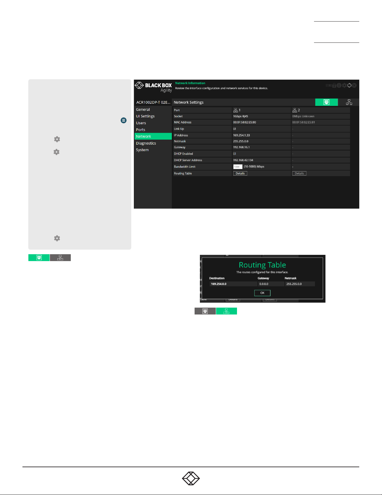
TRANSMITTER - NETWORK
To get here
You can access this page in two ways,
however, the rst method is not available if
the module is under iPATH control:
1 On the console keyboard attached to
the receiver, access the OSD by pressing
CTRL + ALT + C or tap the touchscreen
icon. The Preset Selection page will be
displayed.
2 Click the icon in the top right corner.
3 Click the Local Devices option and then
click the icon for the required
transmitter.
4 If necessary, click the Network link.
OR
1 Connect a computer to the same network
as the transmitter.
2 Run a web browser and enter the IP address
of the transmitter: https://169.254.1.33
(this is the default address when
using port 1). If you are using SFP
port 2, then the default address will be
https://169.254.1.43 Note: These default
addresses can be changed.
3 Click the icon in the top right corner.
4 If necessary, click the Network link.
NEED HELP?
NEED HELP?
LEAVE T HE TECH TO U S
LEAVE T HE TECH TO U S
LIVE 24/7
LIVE 24/7
TECHNICAL
TECHNICAL
SUPPORT
SUPPORT
1.877.877.2269
1.877.877.2269
Routing Table - Click on ‘Details’ to show the routing table entries
corresponding to this network interface. In it are the destination address,
gateway and netmask for the routes to particular network destinations:
Port Settings
This page provides numerous network details for each of the installed
ports on the transmitter.
Socket - Details each operational network socket. Sockets 3 and 4 are
determined by the SFP modules plugged into them.
MAC Address - Displays the unique, xed hardware identication
number for each port.
Link Up - Indicates whether the link state of this network interface is
up. This should be the case if the device is connected to a functioning
network.
IP Address - This shows the IP address in use, which can be obtained
via DHCP, a static IP or a link local (zero-cong).
Netmask - The netmask of this network interface. The device can
function in a network zero-cong state which does not require the
setting of a static netmask.
Gateway - The gateway address of this network interface. The device
can function in a network zero-cong state which does not require the
setting of a static gateway.
Static IP Address - When the ‘DHCP enabled’ option (below) is
unchecked, click on ‘Edit’ to enter/edit a static IP Address, Netmask
and Gateway for the unit.
DHCP Enabled - When ticked, the corresponding port will derive its IP
Address, Netmask and Gateway details from the DHCP server listed in
the eld below.
DHCP Server Address - Indicates the server that provided the DHCP
details.
Bandwidth Limit - This option can be used to set an upper limit
(between 10 and 1000 Mbps aka 1Gbps) to the amount of the network
bandwidth used on the physical interface. This could be useful if
multiple devices share a common network link upstream; without a
limit, the link could become overloaded and drop data.
Network Settings
Default Domain - Reserved for future use.
Route of Last Resort - In a multi interface device such as this, the
interface which is ticked will be used as the default whenever it is unclear
which interface should be used for network trafc.
Dynamic DNS Servers - List of DNS server addresses obtained via DHCP.
Static DNS Servers - Lists DNS server addresses that have been manually
congured.
NTP Enabled - When ticked, the unit will derive its time and date
information from a suitable NTP server.
NTP Key ID - The ID of the key used for secure NTP.
NTP Key Value - The value of the key used for secure NTP as a
hexadecimal string.
Dynamic NTP Servers - Lists NTP server addresses obtained via DHCP.
Static NTP Servers - Lists NTP server addresses that have been manually
congured.
iPATH Enabled - Indicates whether server management is enabled for this
device.
Dynamic iPATH Servers - Lists iPATH server addresses obtained via
DHCP.
Static iPATH Servers - Lists management server addresses that have
been manually congured.
1. 8 7 7. 8 7 7. 2 2 69 BLACKBOX.COM
1. 8 7 7. 8 7 7. 2 2 69 BLACKBOX.COM
51
51
Page 52
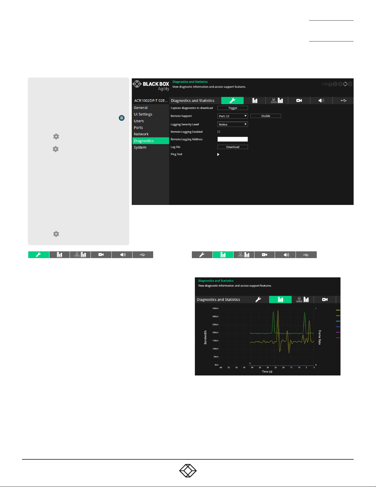
TRANSMITTER - DIAGNOSTICS AND STATISTICS
To get here
You can access this page in two ways,
however, the rst method is not available if
the module is under iPATH control:
1 On the console keyboard attached to
the receiver, access the OSD by pressing
CTRL + ALT + C or tap the touchscreen
icon. The Preset Selection page will be
displayed.
2 Click the icon in the top right corner.
3 Click the Local Devices option and then
click the icon for the required
transmitter.
4 If necessary, click the Diagnostics link.
OR
1 Connect a computer to the same network
as the transmitter.
2 Run a web browser and enter the IP address
of the transmitter: https://169.254.1.33
(this is the default address when
using port 1). If you are using SFP
port 2, then the default address will be
https://169.254.1.43 Note: These default
addresses can be changed.
3 Click the icon in the top right corner.
4 If necessary, click the Diagnostics link.
NEED HELP?
NEED HELP?
LEAVE T HE TECH TO U S
LEAVE T HE TECH TO U S
LIVE 24/7
LIVE 24/7
TECHNICAL
TECHNICAL
SUPPORT
SUPPORT
1.877.877.2269
1.877.877.2269
Log Settings
This page provides numerous key diagnostic log settings.
Capture diagnostics to download - (Only shown when viewing this
page using a PC browser). Request generation of a diagnostics dump
le. This will then be downloaded by the host computer’s browser,
this is an encrypted diagnostics le which can be used by technical
support to diagnose and x an issue.
Remote Support - When using the remote server, this option
determines which port will be used. Multiple options are offered in case
one or more ports are blocked by your rewall. When the Enable button
is clicked, it will indicate the password to be used.
Logging Severity Level - Denes the level of messages that will be
logged (according to RFC5424). Level 5 (Notice: normal but signicant
condition) is the default setting; Agility supports levels 1 to 7. Choosing
levels 6 (Informational) or 7 (Debug) will cause larger numbers of
lesser events to also be logged, with a potential impact to overall
performance. These levels should only be used if working with the
support team to diagnose a specic issue.
Remote Logging Enabled - Tick to send log les to the chosen Remote
Logging Address.
Remote Logging Address - Enter a valid IP address for a syslog server
on the local network where status logs can be sent.
Log File - If viewing this page using a browser: Click to download the log
le to the host computer’s browser. If viewing this page via the OSD, the
log will be shown as a scrollable list.
Ping Test - Provides a quick and easy way to check the link status to a
receiver. You can specify either an IP address or choose the device from
a list. Click the Start button to begin; a summary of the results will be
displayed.
Basic Graph
This page shows a real time graph with the following entries:
• Received and transmitted bit rates - the values of these correspond to
the bandwidth axis on the left.
• Frame rate - for both heads. Values are labeled when they change and
correspond to the axis on the right.
• Codec - for both heads. These represent the compression used: 1 is
better than 4.
52
52
1. 8 7 7. 8 7 7. 2 2 69 BLACKBOX.COM
1. 8 7 7. 8 7 7. 2 2 69 BLACKBOX.COM
Page 53
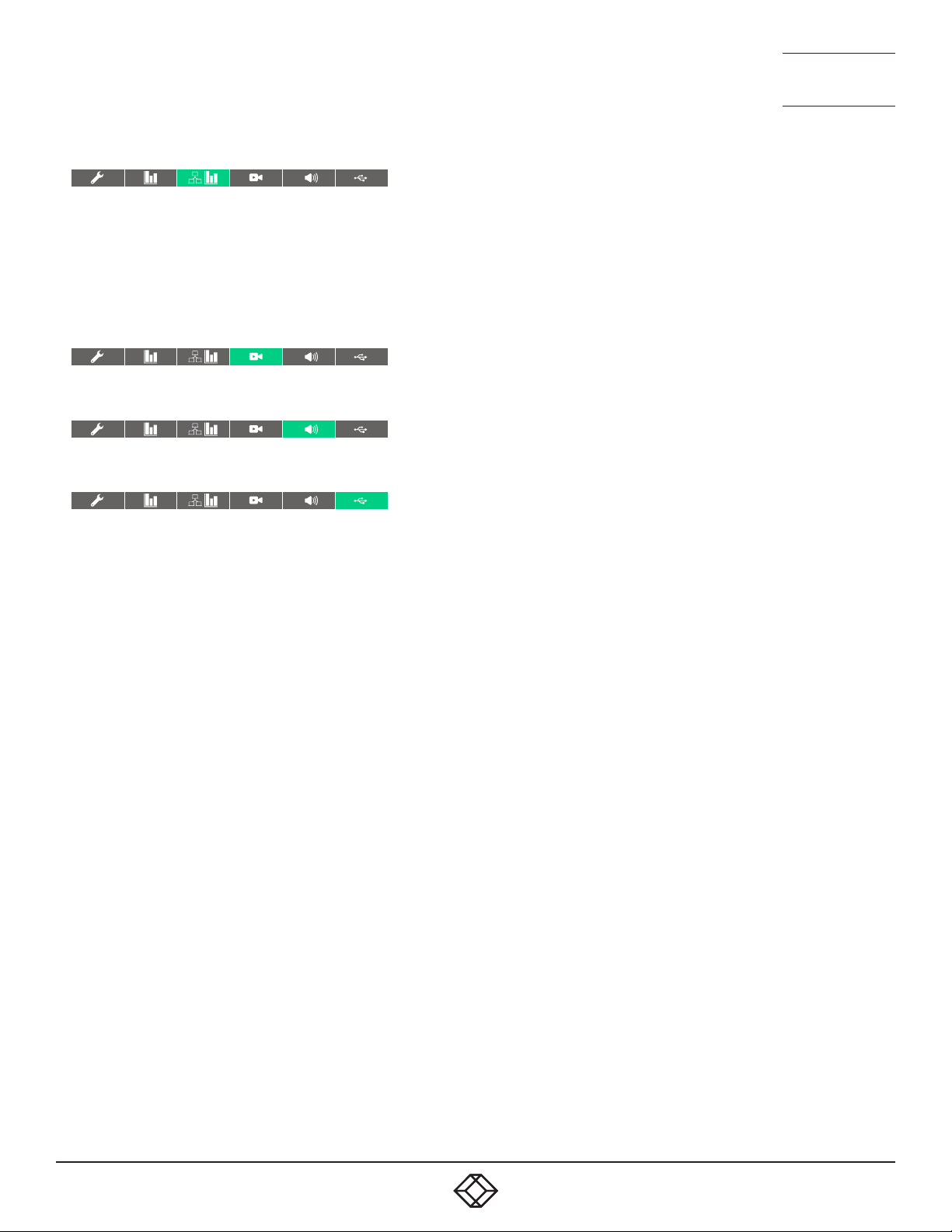
Network Statistics
This page allows you to view current communication statistics and
also to create graphs in real time.
Capture and Graph Statistics - When ticked, the page will create a real
time graph plotting Received Bytes alongside Received Packets.
After Capture and Graph Statistics is enabled, the Show Legend
checkbox will show all other items that can be included on the plot.
Click an item to tick and include it.
Video Port Status and Statistics
This page provides wide ranging information for support purposes.
Audio Port Status and Statistics
This page provides wide ranging information for support purposes.
NEED HELP?
NEED HELP?
LEAVE T HE TECH TO U S
LEAVE T HE TECH TO U S
LIVE 24/7
LIVE 24/7
TECHNICAL
TECHNICAL
SUPPORT
SUPPORT
1.877.877.2269
1.877.877.2269
USB Port Status and Statistics
Not yet implemented.
1. 8 7 7. 8 7 7. 2 2 69 BLACKBOX.COM
1. 8 7 7. 8 7 7. 2 2 69 BLACKBOX.COM
53
53
Page 54
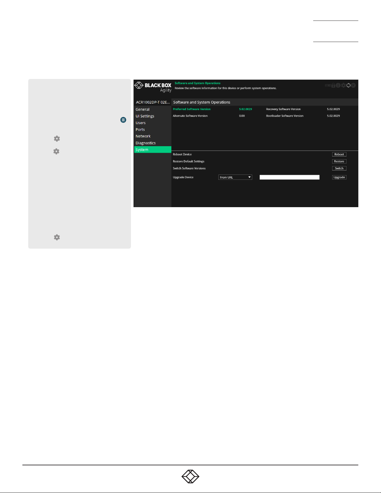
TRANSMITTER - SYSTEM
To get here
You can access this page in two ways,
however, the rst method is not available if
the module is under iPATH control:
1 On the console keyboard attached to
the receiver, access the OSD by pressing
CTRL + ALT + C or tap the touchscreen
icon. The Preset Selection page will be
displayed.
2 Click the icon in the top right corner.
3 Click the Local Devices option and then
click the icon for the required
transmitter.
4 If necessary, click the System link.
OR
1 Connect a computer to the same network
as the transmitter.
2 Run a web browser and enter the IP address
of the transmitter: https://169.254.1.33
(this is the default address when
using port 1). If you are using SFP
port 2, then the default address will be
https://169.254.1.43 Note: These default
addresses can be changed.
3 Click the icon in the top right corner.
4 If necessary, click the System link.
NEED HELP?
NEED HELP?
LEAVE T HE TECH TO U S
LEAVE T HE TECH TO U S
LIVE 24/7
LIVE 24/7
TECHNICAL
TECHNICAL
SUPPORT
SUPPORT
1.877.877.2269
1.877.877.2269
Software and System Operations
This page contains various indications and options related to the
internal software of the unit.
Note: The highlighted (and colored) entry is the version of software
currently running.
Preferred Software Version - The software version the device will boot
into upon a reboot.
Recovery Software Version - The software version the device will boot
into if placed into recovery mode.
Alternate Software Version - The other (backup) version of software
the device has available.
Reboot Device - Click the Reboot button to Reboot the device.
Restore Default Settings - Click the Restore button to restore the
device to factory default settings.
Switch Software Versions - Click to switch to the listed ‘Alternative
Software Version’.
Upgrade Device - Allows you to upgrade the rmware either from a
trusted URL or from a locally stored le. Use the eld to dene the
source and then click the Upgrade button.
54
54
1. 8 7 7. 8 7 7. 2 2 69 BLACKBOX.COM
1. 8 7 7. 8 7 7. 2 2 69 BLACKBOX.COM
Page 55
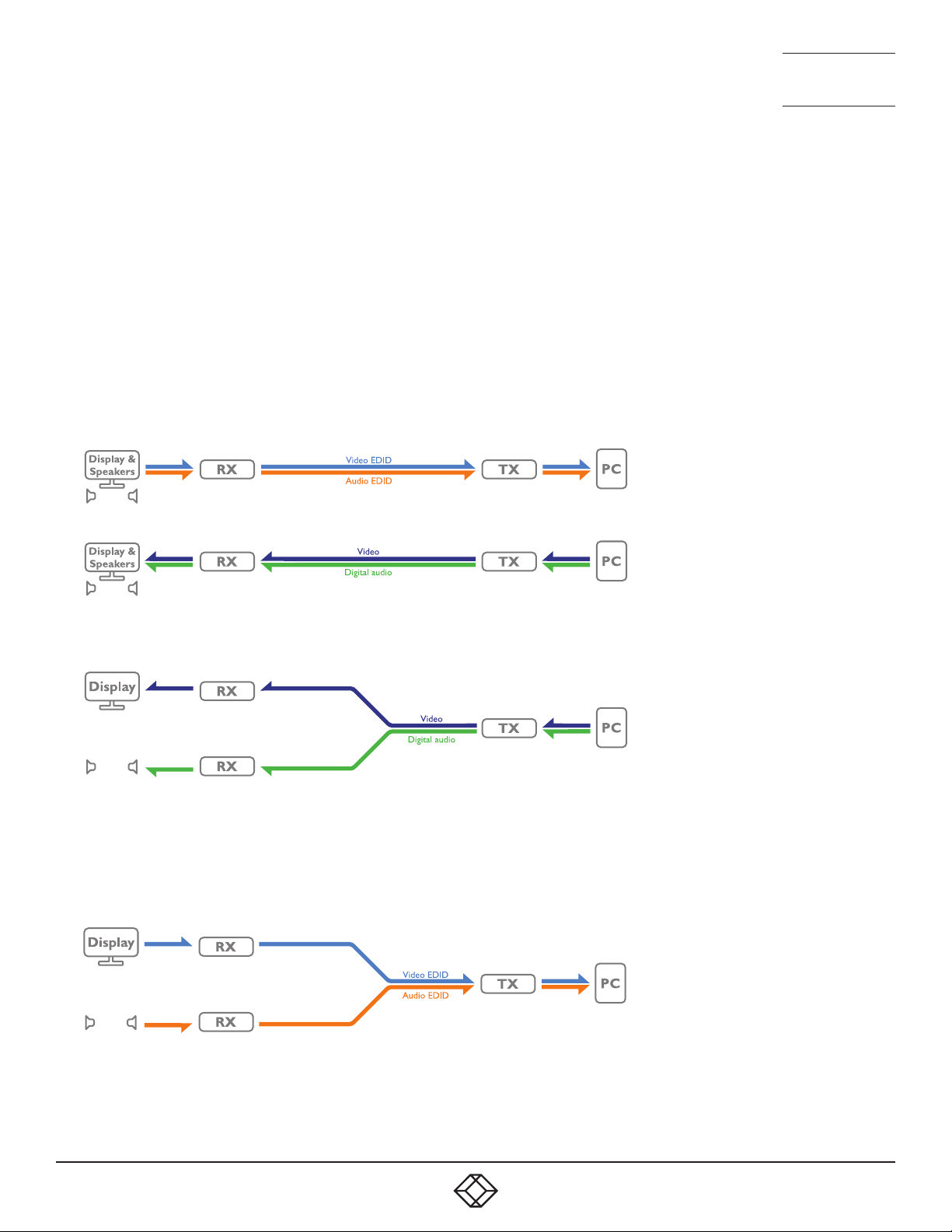
NEED HELP?
LEAVE T HE TECH TO U S
LIVE 24/7
TECHNICAL
SUPPORT
1.877.877.2269
APPENDIX B - Support for analog and digital audio
The ACR1002 range benefits from multiple audio signal streams:
• Uni-directional analog audio - from the host PCs jack socket,
• Uni-directional digital audio - via the video connection,
• Bi-directional digital audio - via the USB connection (converted to/from analog).
Even though the analog and digital outputs from a particular host PC might be carrying signals that originated from the same
audio source, they are handled separately throughout the ACR1002 system and can never be mixed.
For digital audio derived from the video connection, the host PC needs to know details of the required signal to send out, eg 16 or
24-bit, 48, 88.2 or 96kHz sample rate, etc, so a valid definition of the requirement must be sent to the host PC. This is done as an
audio sub-set of the EDID definition that is used to declare the video display capabilities/requirements.
In the diagram below the display and speaker installation send their video and digital audio portions of the EDID (Extended
Display Identification Data) definition via the ACR1002 receiver and transmitter to the host PC:
In response, the host PC begins sending video and audio signals that are appropriate for the receiving peripherals:
In the above case, the video and digital audio from the host PC are both sent to the same receiver. However, the flexibility of the
ACR1002 system is such that peripherals and hosts can be mixed as required. For instance, the video feed could be sent to one
receiver, while the digital audio is used by a set of speakers on a different receiver:
Notes:
• ACR1002 units support only two channel stereo audio and the transmitters will not encode digital audio from a PC with more
than 2 channels.
This presents an issue for the host PC and its ALIF2100 transmitter as they must now respond to separate EDID definitions from
the video display on one receiver (which will probably also have its own EDID audio sub-set) and the EDID definition from the
digital audio device on the other receiver:
1. 8 7 7. 8 7 7. 2 2 69 BLACKBOX.COM
continued
55
Page 56

NEED HELP?
LEAVE T HE TECH TO U S
LIVE 24/7
TECHNICAL
SUPPORT
1.877.877.2269
To solve potential conflicts, the ACR1002 transmitter uses a set of rules to determine how it mixes different EDID definitions.
Firstly, for any connected video or digital audio devices, the ACR1002 system can consider each one using any of three selectable
states:
• Attached - ACR1002 will interrogate the attached video/audio device to ascertain its exact capabilities/requirements.
• Fixed - ACR1002 will use a fixed definition (e.g 1920x1080p60 and 2-channel audio) to represent the video/audio device(s).
• None - No representation will be made for the device.
The above states are then combined by the ACR1002 transmitter, as connections are made to the different devices, using the
following rules:
Video EDID Audio EDID Action (taken by the TX as it feeds info to the PC)
Fixed Fixed Merge the video and audio EDID definitions.
Fixed/Attached None Send video EDID definition only.
Attached Attached Use whichever EDID definition is available first.
Attached/Fixed Fixed/Attached Wait for the Attached device to declare and then
use its data to modify those of the Fixed
device. Note: The video EDID retains precedence
for setting general items, such as serial no.,
manufacturer, etc.
Note: The analog audio is switched entirely separately to the digital audio feed.
ANALOG AND DIGITAL AUDIO SPECIFICATIONS
• Analog audio: Line in/out - 2 channel 16bit 48KHz 1V RMS in / 1V RMS out
• Digital audio (DisplayPort™ or HDMI):
Up to 2 audio channels,
Five choices of sampling frequencies: 32, 44.1, 48, 88.2 or 96kHz.
Three choices of bit depth, using LPCM Linear Pulse Code Modulation: 16, 20 or 24bit,
56
1. 8 7 7. 8 7 7. 2 2 69 BLACKBOX.COM
Page 57

NEED HELP?
LEAVE T HE TECH TO U S
LIVE 24/7
TECHNICAL
SUPPORT
1.877.877.2269
APPENDIX C - TIPS FOR SUCCESS WHEN NETWORKING AGILITY UNITS
Agility units use multiple strategies to minimize the amount of data that they send across networks. However, data overheads
can be quite high, particularly when very high resolution video is being transferred, so it is important to take steps to maximize
network efficiency and help minimize data output. The tips given in this section have been proven to produce very beneficial
results.
SUMMARY OF STEPS
• Choose the right kind of switch.
• Create an efficient network layout.
• Configure the switches and devices correctly.
CHOOSING THE RIGHT SWITCH
Layer 2 switches are what bind all of the hosts together in the subnet. However, they are all not created equally, so choose
carefully. In particular look for the following:
• 10Gigabit ports,
• Support for IGMP v2 (or v3) snooping,
• Support for Jumbo frames up to 9216-byte size,
• High bandwidth connections between switches, preferably Fiber Channel.
• Look for switches that perform their most onerous tasks (e.g., IGMP snooping) using multiple dedicated processors (ASICS).
• Ensure the maximum number of concurrent ‘snoopable groups’ the switch can handle meets or exceeds the number of Agility
transmitters that will be used to create multicast groups.
• Check the throughput of the switch: Full duplex, 10Gbps up- and down- stream speeds per port.
• Use the same switch make and model throughout a single subnet.
• You also need a Layer 3 switch. Ensure that it can operate efficiently as an IGMP Querier.
CREATING AN EFFICIENT NETWORK LAYOUT
Network layout is vital. The use of IGMP snooping also introduces certain constraints, so take heed:
• Keep it flat. Use a basic line-cascade structure rather than a pyramid or tree arrangement.
• Keep the distances between the switches as short as possible.
• Ensure sufficient bandwidth between switches to eliminate bottlenecks.
• Where the iPATH server is used to administer multiple Agility transceivers, ensure the iPATH server and all Agility units reside in
the same subnet.
• Do not use VGA to DisplayPort™ converters, instead replace VGA video cards in older systems with suitable DisplayPort
replacements. Converters cause transmitters to massively increase data output.
• Wherever possible, create a private network.
1. 8 7 7. 8 7 7. 2 2 69 BLACKBOX.COM
57
Page 58
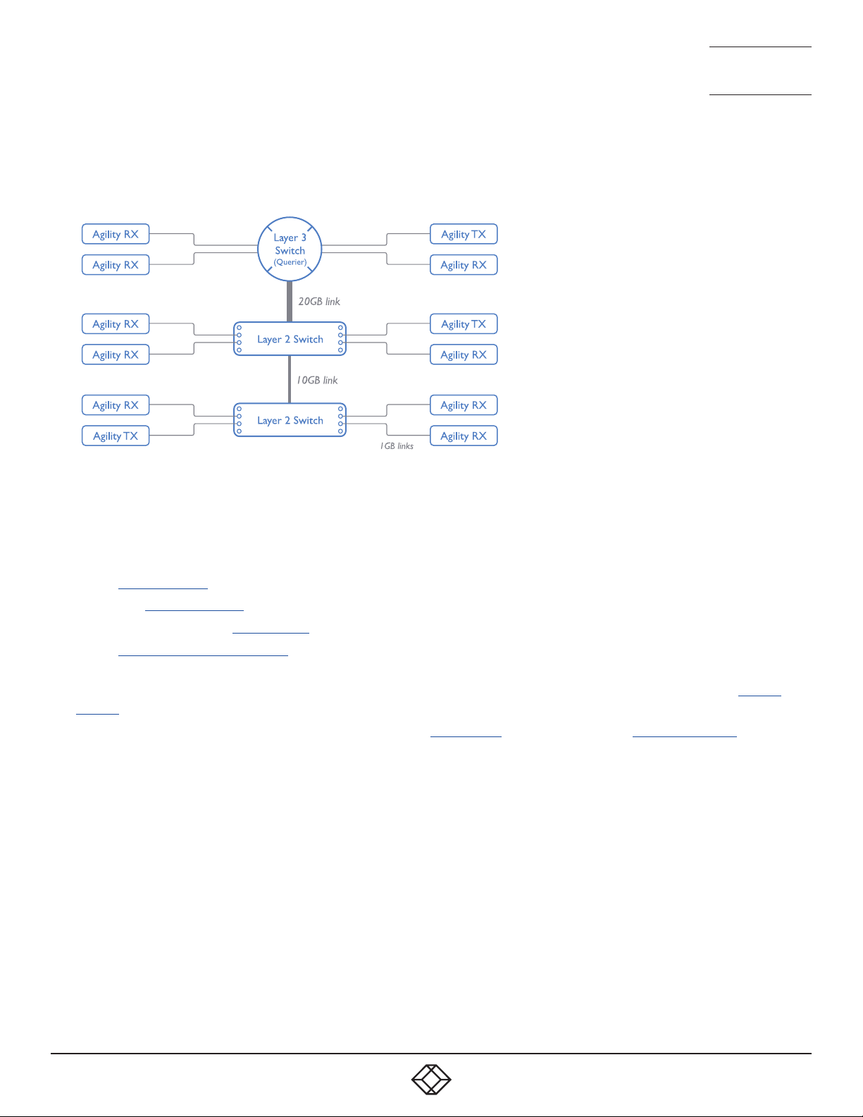
NEED HELP?
LEAVE T HE TECH TO U S
LIVE 24/7
TECHNICAL
SUPPORT
1.877.877.2269
THE RECOMMENDED LAYOUT
The layout shown below has been found to provide the most efficient network layout for rapid throughput when using IGMP
snooping:
• Use no more than two cascade levels.
• Ensure high bandwidth between the two L2 switches and very high bandwidth between the top L2 and the L3. Typically 10GB
and 20GB, respectively for 48 port L2 switches.
CONFIGURING THE SWITCHES AND DEVICES
The layout is vital but so too is the configuration:
• Enable IGMP Snooping on all L2 switches.
• Ensure that IGMP Fast-Leave is enabled on all switches with Agility units connected directly to them.
• Enable the L3 switch as an IGMP Querier.
• Enable Spanning Tree Protocol (STP) on all switches and importantly also enable portfast (only) on all switch ports that have
Agility units connected.
• If any hosts will use any video resolutions using 2048 horizontal pixels (e.g. 2048 x 1152, 2048 x 2048), ensure that Jumbo
Frames are enabled on all switches.
• Choose an appropriate forwarding mode on all switches. Use Cut-through if available, otherwise Store and forward.
• Optimize the settings on the Agility transmitters:
• If moving video images are being shown frequently, then leave Frame Skipping at a low percentage and instead reduce the
Peak bandwidth limiter.
• Where screens are quite static, try increasing the Background Refresh interval and/or increasing the Frame skipping
percentage setting.
Make changes to the Agility transmitters one at a time, in small steps, and view typical video images so that you can attribute
positive or negative results to the appropriate control.
• Ensure that all Agility units are fully updated to the latest firmware version (at least v2.1).
58
1. 8 7 7. 8 7 7. 2 2 69 BLACKBOX.COM
Page 59

NEED HELP?
LEAVE T HE TECH TO U S
LIVE 24/7
TECHNICAL
SUPPORT
1.877.877.2269
APPENDIX D - TROUBLESHOOTING
PROBLEM: THE VIDEO IMAGE OF THE AGILITY RECEIVER SHOWS HORIZONTAL LINES ACROSS THE SCREEN.
This issue is known as Blinding because the resulting video image looks as though you’re viewing it through a venetian blind.
When video is transmitted by Agility units, the various lines of each screen are divided up and transmitted as separate data
packets. If the reception of those packets is disturbed, then blinding is caused. The lines are displayed in place of the missing
video data packets.
There are several possible causes for the loss of data packets:
• Incorrect switch configuration. The problem could be caused by multicast flooding, which causes unnecessary network traffic.
This is what IGMP snooping is designed to combat, however, there can be numerous causes of the flooding.
• Speed/memory bandwidth issues within one or more switches. The speed and capabilities of different switch models varies
greatly. If a switch cannot maintain pace with the quantity of data being sent through it, then it will inevitably start dropping
packets.
• One or more Agility units may be outputting Jumbo frames due to the video resolution (2048 horizontal pixels) being used.
If Jumbo frames are output by an Agility unit, but the network switches have not been configured to use jumbo frames, the
switches will attempt to break the large packets down into standard packets. This process introduces a certain latency and
could be a cause for dropped packets.
• One or more Agility units may be using an old firmware version. Firmware versions prior to v2.1 exhibited an issue with the
timing of IGMP join and leave commands that caused multicast flooding in certain configurations.
REMEDIES:
• Ensure that IGMP snooping is enabled on all switches within the subnet.
• Where each Agility unit is connected as the sole device on a port connection to a switch, enable IGMP Fast-Leave (aka
Immediate Leave) to reduce unnecessary processing on each switch.
• Check the video resolution(s) being fed into the Agility transmitters. If resolutions using 2048 horizontal pixels are unavoidable
then ensure that Jumbo frames are enabled on all switches.
• Check the forwarding mode on the switches. If Store and forward is being used, try selecting Cut-through as this mode causes
reduced latency on lesser switch designs.
• Ensure that one device within the subnet is correctly configured as an IGMP Querier, usually a layer 3 switch or multicast router.
• Ensure that the firmware in every Agility unit is version 2.1 or greater.
• Try adjusting the transmitter settings on each Agility to make the output data stream as efficient as possible. See Agility
transmitter video settings for details.
PROBLEM: THE AUDIO OUTPUT OF THE AGILITY RECEIVER SOUNDS LIKE A SCRATCHED RECORD.
This issue is called Audio crackle and is a symptom of the same problem that produces blinding (see previous page). The issue is
related to missing data packets.
REMEDIES:
As per blinding discussed previously.
1. 8 7 7. 8 7 7. 2 2 69 BLACKBOX.COM
59
Page 60

NEED HELP?
LEAVE T HE TECH TO U S
LIVE 24/7
TECHNICAL
SUPPORT
1.877.877.2269
PROBLEM: IPATH CANNOT LOCATE WORKING AGILITY UNITS.
There are a few possible causes:
• The Agility units must be reset back to their zero config IP addresses for iPATH discovery. If you have a working network of
Agility units without iPATH and then add iPATH to the network, iPATH will not discover the Agility units until they are reset to the
zero config IP addresses.
• This could be caused by Layer 2 Cisco switches that have Spanning Tree Protocol (STP) enabled but do not also have portfast
enabled on the ports to which Agility units are connected. Without portfast enabled, Agility units will all be assigned the same
zero config IP address at reboot and iPATH will only acquire them one at a time on a random basis.
You can easily tell whether portfast is enabled on a switch that is running STP: When you plug the link cable from a working
Agility unit into the switch port, check how long it takes for the port indicator to change from orange to green. If it takes roughly
one second, portfast is on; if it takes roughly thirty seconds then portfast is disabled.
REMEDIES:
• Ensure that the Agility units and the iPATH server are located within the same subnet because iPATH cannot cross subnet
boundaries.
• Manually reset the Agility units to their zero config IP addresses.
• Enable portfast on all switch ports that have Agility units attached to them or try temporarily disabling STP on the switches
while iPATH is attempting to locate Agility units.
60
1. 8 7 7. 8 7 7. 2 2 69 BLACKBOX.COM
Page 61

NEED HELP?
LEAVE T HE TECH TO U S
LIVE 24/7
TECHNICAL
SUPPORT
1.877.877.2269
APPENDIX E - GLOSSARY
INTERNET GROUP MANAGEMENT PROTOCOL
Where an Agility transmitter is required to stream video to two or more receivers, multicasting is the method used.
Multicasting involves the delivery of identical data to multiple receivers simultaneously without the need to maintain individual links.
When multicast data packets enter a subnet, the natural reaction of the switches that bind all the hosts together within the subnet is
to spread the multicast data to all of their ports. This is referred to as Multicast flooding and means that the hosts (or at least their
network interfaces) are required to process plenty of data that they didn’t request. IGMP offers a partial solution.
The Internet Group Management Protocol (IGMP) is designed to prevent multicast flooding by allowing Layer 3 switches to
check whether host computers within their care are interested in receiving particular multicast transmissions. They can then direct
multicast data only to those points that require it and can shut off a multicast stream if the subnet has no recipients.
There are currently three IGMP versions: 1, 2 and 3, with each version building upon the capabilities of the previous one:
• IGMPv1 allows host computers to opt into a multicast transmission using a Join Group message, it is then incumbent on the
router to discover when they no longer wish to receive; this is achieved by polling them (see IGMP Querier below) until they no
longer respond.
• IGMPv2 includes the means for hosts to opt out as well as in, using a Leave Group message.
• IGMPv3 encompasses the abilities of versions 1 and 2 but also adds the ability for hosts to specify particular sources of
multicast data.
Black Box Agility units make use of IGMPv2 when performing multicasts to ensure that no unnecessary congestion is caused.
IGMP SNOOPING
The IGMP messages are effective but only operate at layer 2 - intended for routers to determine whether multicast data should
enter a subnet. A relatively recent development has taken place within the switches that glue together all of the hosts within each
subnet: IGMP Snooping. IGMP snooping means these layer 2 devices now have the ability to take a peek at the IGMP messages.
As a result, the switches can then determine exactly which of their own hosts have requested to receive a multicast – and only
pass on multicast data to those hosts.
IGMP QUERIER
When IGMP is used, each subnet requires one Layer 3 switch to act as a Querier. In this lead role, the switch periodically sends
out IGMP Query messages and in response all hosts report which multicast streams they wish to receive. The Querier device and
all snooping Layer 2 switches then update their lists accordingly (the lists are also updated when Join Group and Leave Group
(IGMPv2) messages are received).
IGMP FAST-LEAVE (AKA IMMEDIATE LEAVE)
When a device/host no longer wishes to receive a multicast transmission, it can issue an IGMP Leave Group message as
mentioned above. This causes the switch to issue an IGMP Group-Specific Query message on the port (that the Leave Group was
received on) to check no other receivers exist on that connection that wish to remain a part of the multicast. This process has a
cost in terms of switch processor activity and time.
Where Agility units are connected directly to the switch (with no other devices on the same port) then enabling IGMP Fast-Leave
mode means that switches can immediately remove receivers without going through a full checking procedure. Where multiple
units are regularly joining and leaving multicasts, this can speed up performance considerably.
JUMBO FRAMES (JUMBO PACKETS)
Since its commercial introduction in 1980, the Ethernet standard has been successfully extended and adapted to keep pace with
the ever improving capabilities of computer systems. The achievable data rates, for instance, have risen in ten-fold leaps from the
original 10Mbit/s to a current maximum of 100Gbit/s.
While data speeds have increased massively, the standard defining the number of bytes (known as the Payload) placed into each
data packet has remained resolutely stuck at its original level of 1500 bytes. This standard was set during the original speed era
1. 8 7 7. 8 7 7. 2 2 69 BLACKBOX.COM
61
Page 62

NEED HELP?
LEAVE T HE TECH TO U S
LIVE 24/7
TECHNICAL
SUPPORT
1.877.877.2269
(10Mbits/s) and offered the best compromise at that speed between the time taken to process each packet and the time required
to resend faulty packets due to transmission errors.
But now networks are much faster and files/data streams are much larger; so time for a change? Unfortunately, a wholesale
change to the packet size is not straightforward as it is a fundamental standard and changing it would mean a loss of backward
compatibility with older systems.
Larger payload options have been around for a while, however, they have often been vendor specific and at present they remain
outside the official standard. There is, however, increased consensus on an optional ‘Jumbo’ payload size of 9000 bytes and this
is fully supported by the Agility units.
Jumbo frames (or Jumbo packets) offer advantages for Agility units when transmitting certain high resolution video signals
across a network. This is because the increased data in each packet reduces the number of packets that need to be transferred
and dealt with - thus reducing latency times.
The main problem is that for jumbo frames to be possible on a network, all of the devices on the network must support them.
SPANNING TREE PROTOCOL (STP)
In order to build a robust network, it is necessary to include certain levels of redundancy within the interconnections between
switches. This will help to ensure that a failure of one link does not lead to a complete failure of the whole network.
The danger of multiple links is that data packets, especially multicast packets, become involved in continual loops as
neighbouring switches use the duplicated links to send and resend them to each other.
To prevent such bridging loops from occurring, the Spanning Tree Protocol (STP), operating at layer 2, is used within each
switch. STP encourages all switches to communicate and learn about each other. It prevents bridging loops by blocking newly
discovered links until it can discover the nature of the link: is it a new host or a new switch?
The problem with this is that the discovery process can take up to 50 seconds before the block is lifted, causing problematic
timeouts.
The answer to this issue is to enable the portfast variable for all host links on a switch. This will cause any new connection to go
immediately into forwarding mode. However, take particular care not to enable portfast on any switch to switch connections as
this will result in bridging loops.
FORWARDING MODES
In essence, the job of a layer 2 switch is to transfer as fast as possible, data packets arriving at one port out to another port as
determined by the destination address. This is known as data forwarding and most switches offer a choice of methods to achieve
this. Choosing the most appropriate forwarding method can often have a sizeable impact on the overall speed of switching:
• Store and forward is the original method and requires the switch to save each entire data packet to buffer memory, run an error
check and then forward if no error is found (or otherwise discard it).
• Cut-through was developed to address the latency issues suffered by some store and forward switches. The switch begins
interpreting each data packet as it arrives. Once the initial addressing information has been read, the switch immediately
begins forwarding the data packet while the remainder is still arriving. Once all of the packet has been received, an error check
is performed and, if necessary, the packet is tagged as being in error. This checking ‘on-the-fly’ means that cut-through
switches cannot discard faulty packets themselves. However, on receipt of the marked packet, a host will carry out the discard
process.
• Fragment-free is a hybrid of the above two methods. It waits until the first 64 bits have been received before beginning to
forward each data packet. This way the switch is more likely to locate and discard faulty packets that are fragmented due to
collisions with other data packets.
• Adaptive switches automatically choose between the above methods. Usually they start out as a cut-through switches and
change to store and forward or fragment-free methods if large number of errors or collisions are detected.
So which one to choose? The Cut-through method has the least latency so is usually the best to use with Agility units. However,
62
1. 8 7 7. 8 7 7. 2 2 69 BLACKBOX.COM
Page 63
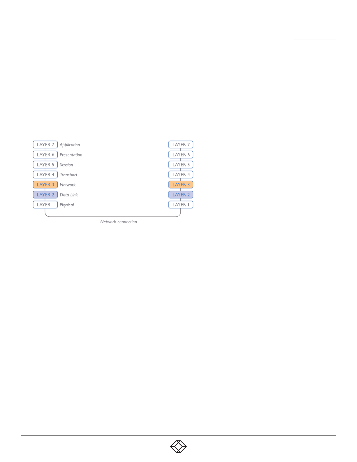
NEED HELP?
LEAVE T HE TECH TO U S
LIVE 24/7
TECHNICAL
SUPPORT
1.877.877.2269
if the network components and/or cabling generate a lot of errors, the Store and forward method should probably be used. On
higher end store and forward switches, latency is rarely an issue.
LAYER 2 AND LAYER 3: THE OSI MODEL
When discussing network switches, the terms Layer 2 and Layer 3 are very often used. These refer to parts of the Open System
Interconnection (OSI) model, a standardized way to categorize the necessary functions of any standard network.
There are seven layers in the OSI model and these define the steps needed to get the data created by you (imagine that you are
Layer 8) reliably down onto the transmission medium (the cable, optical fiber, radio wave, etc.) that carries the data to another
user; to complete the picture, consider the transmission medium is Layer 0. In general, think of the functions carried out by the
layers at the top as being complex, becoming less complex as you go lower down.
As your data travel down from you towards the transmission medium (the cable), they are successively encapsulated at each
layer within a new wrapper (along with a few instructions), ready for transport. Once transmission has been made to the intended
destination, the reverse occurs: Each wrapper is stripped away and the instructions examined until finally only the original data
are left.
So why are Layer 2 and Layer 3 of particular importance when discussing Agility units? Because the successful transmission of
data relies upon fast and reliable passage through network switches – and most of these operate at either Layer 2 or Layer 3.
The job of any network switch is to receive each incoming network packet, strip away only the first few wrappers to discover the
intended destination then rewrap the packet and send it in the correct direction.
In simplified terms, the wrapper that is added at Layer 2 (by the sending system) includes the physical address of the intended
recipient system, i.e. the unique MAC address (for example, 09:f8:33:d7:66:12) that is assigned to every networking device at
manufacture. Deciphering recipients at this level is more straightforward than at Layer 3, where the address of the recipient is
represented by a logical IP address (e.g. 192.168.0.10) and requires greater knowledge of the surrounding network structure. Due
to their more complex circuitry, Layer 3 switches are more expensive than Layer 2 switches of a similar build quality and are used
more sparingly within installations.
1. 8 7 7. 8 7 7. 2 2 69 BLACKBOX.COM
63
Page 64

NEED HELP?
LEAVE T HE TECH TO U S
LIVE 24/7
TECHNICAL
SUPPORT
1.877.877.2269
APPENDIX F - FIBER/COPPER MODULES AND CABLES
To suit your installation layout, fiber and copper modules are available for the Agility units to support various fiber optic and CATx
cables. The specifications for all are summarized in this table:
Name Fiber size Type Coding Distance
Normal
Suggested print nomenclature
applications
OM1 (62.5/125) Multimode
Orange 62.5/125 220m
(TIA-492AAAA)
OM2 (50/125) Multimode
Orange 50/125 550m
(TIA-492AAAB)
OM3 (50/125) Multimode
Aqua 850 LO 50 /125 550m
(850 nm Laser-optimized)
(TIA-492AAAC)
OM4 (50/125) Multimode
Aqua 850 LO 50 /125 550m
(850 nm Laser-optimized)
(TIA-492AAAC)
OS1 and
OS2
(9/125) Single-mode
(TIA-492C000 / TIA-
Yellow SM/NZDS, SM 20km
492E000)
CATx n/a CAT5e and above n/a n/a 100m
at 1Gbps
64
1. 8 7 7. 8 7 7. 2 2 69 BLACKBOX.COM
Page 65
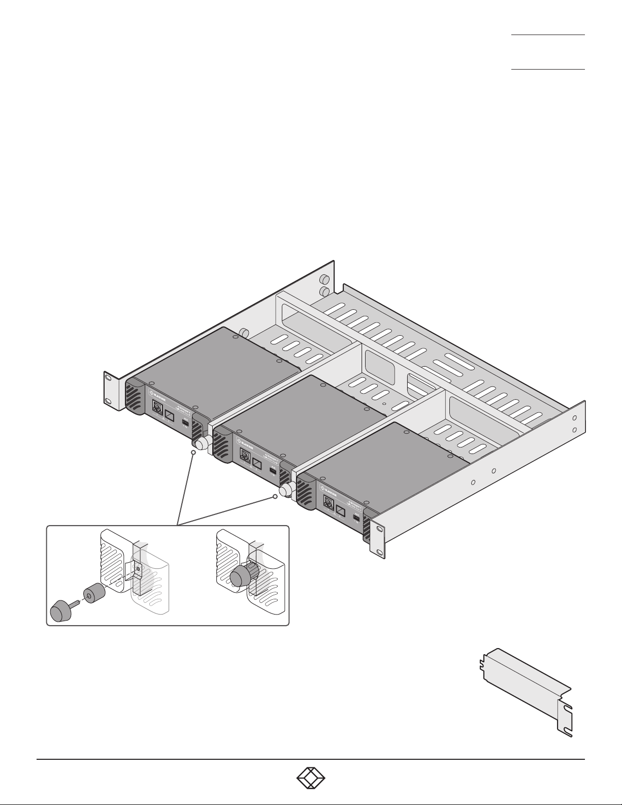
NEED HELP?
LEAVE T HE TECH TO U S
LIVE 24/7
TECHNICAL
SUPPORT
1.877.877.2269
APPENDIX G - USING THE OPTIONAL AGILITY RACK SHELVES
ACR-RMK3 RACK MOUNT FOR AGILITY ACR1002DP AND ACR1002FDP TRANSMITTERS
1 Install the empty rack mount into your 19” rack frame and fully secure it.
2 Place compatible modules into the three bays of the rack mount so that their rear panels butt up against the small pegs located
on each of the side walls.
3 Locate the supplied thumbscrews and spacers.
4 Insert the thumbscrew through the spacer; then insert into the small hole at the end of a divider (A).
5 Gently tighten the thumbscrew so that the spacer engages with the inner edges of the modules that are either side of the
divider to hold them in place (B).
6 Repeat steps 4 and 5 for the other thumbscrew and
spacer.
7 Place the power adapters in the rear section
of the rack mount and connect them
to their respective modules.
8 Make all other necessary
connections to the
modules.
IMPORTANT: When mounting the Agility
units (and their power adapters), ensure
that the vents are not obscured and that
there is sufficient airflow. The operating
temperature range is 0 to 40ºC (0 to
104ºF) and must not be exceeded.
(A)
(B)
USING A BLANKING PLATE WHEN A SINGLE MODULE IS INSTALLED
In order to maintain suitable cooling airflow, if only two modules are installed within the rack
mount, you are recommended to install an optional blanking plate: ACR-RMK3-BP
Note: The outer edge of the blanking plate needs to overlap the ears of the rack mount itself, so you
need to either install the blanking plate before the tray is installed or briefly remove the mounting
bolts on the blanked side (while supporting the weight of the tray) to allow the blanking plate to be
put in place.
1. 8 7 7. 8 7 7. 2 2 69 BLACKBOX.COM
ACR-RMK3-BP
blanking plate
65
Page 66
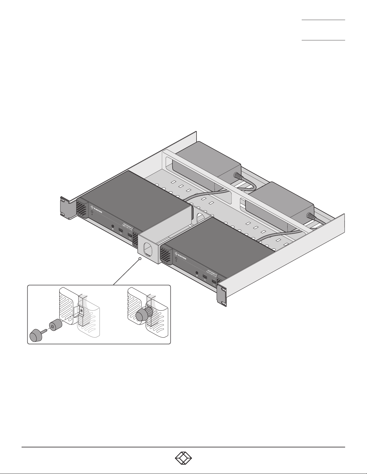
NEED HELP?
LEAVE T HE TECH TO U S
LIVE 24/7
TECHNICAL
SUPPORT
1.877.877.2269
KVXHP-RMK RACK MOUNT FOR AGILITY ACR1002DP AND ACR1002FDP RECEIVERS
1 Install the empty rack mount into your 19” rack frame and fully secure it.
2 Place a compatible module into each side of the rack mount so that their rear panels butt up against the small pegs located on
each of the side walls.
3 Locate the supplied thumbscrew and spacer.
4 Insert the thumbscrew through the spacer; then insert into the small hole at the end of the center divider (A).
5 Gently tighten the thumbscrew so that the spacer engages with the
inner edges of the two modules and holds them in place (B).
6 Place the power adapters in the rear section of
the rack mount and connect them to their
respective modules.
7 Make all other necessary
connections to the modules.
(A)
(B)
ACR-RMK3 and KVXHP-RMK rack mounts:
Suitable for installation in Information Technology Rooms in accordance with
Article 645 of the National Electrical Code and NFPA 75.
Peut être installé dans des salles de matériel de traitement de l’information
conformément à l’article 645 du National Electrical Code et à la NFPA 75.
66
1. 8 7 7. 8 7 7. 2 2 69 BLACKBOX.COM
IMPORTANT: When mounting the Agility units (and
their power adapters), ensure that the vents are
not obscured and that there is sufficient airflow.
The operating temperature range is 0 to 40ºC (0 to
104ºF) and must not be exceeded.
Page 67

NEED HELP?
NEED HELP?
LEAVE T HE TECH TO U S
LEAVE T HE TECH TO U S
LIVE 24/7
LIVE 24/7
TECHNICAL
TECHNICAL
SUPPORT
SUPPORT
1.877.877.2269
1.877.877.2269
APPENDIX H - OPEN SOURCE LICENSES
The software included in this product contains copyrighted
software that is licensed under the GNU General
Public License (GPL) v2. You may obtain the complete
Corresponding Source Code from Black Box for a period of
three years after the last shipment of this product, which will
be no earlier than 2028, by contacting [email protected]
Please write “Source for product XXXXXXXX” in the subject
line, where XXXXXXXX is the model and version number.
This offer is valid to anyone in receipt of this information.
dtc
u-boot-xlnx
linux/linux
busybox
termcap
util-linux
libcap
systemd
iproute2
e2fsprogs
rng-tools
libfftw
db us-1
freetype
qt5
libpbe
A complete copy of the GNU General Public License v2 license text is
inclu ded at the end of this file.
This product includes binaries that are derived from the open source
community. The modules listed below are licenced under the GNU Lesser
General Public License v2.1 and must be provided, in source form, on
request:
kmod
systemd
libdaemon
avahi
gnutls
glib
libgpg-error
libgcrypt
libmicrohttpd
strace
A complete copy of the GNU Lesser General Public License v2.1 license text is included at
the end of this file .
This product includes binaries that are derived from the open source
community. The modules listed below are licenced under the GNU Lesser
General Public License v3 and must be provided, in source form, on
request:
libunistring
gmp
nettle
A complete copy of the GNU Lesser General Public License v3 license text is
inclu ded at the end of this file.
This product includes binaries that are derived from the open source
community. The modules listed below are licenced under the Mozilla Public
License Version 2.0 and must be p rovided, in source form, on request:
dhcp
libjwt
A complete copy of the Mozilla Public License Version 2.0 license text is
inclu ded at the end of this file.
In addition to the GPL modules listed, this product also includes
binaries derived from 3rd party open sources that have their own
license requirements. Each module is listed be low with their required
Copyright statement and distribution conditions.
----------------------------------------------------------------------------
-
- Module: freebsd-libc
-
----------------------------------------------------------------------------
# @(#)COPYRIGHT 8.2 (B erkeley) 3/21/94
All of the documentation and software included in the 4.4BSD and 4.4BSD-Lite
Releases is copyr ighted by The Regents of th e Universit y of California.
Co pyri ght 1979, 19 80, 1983, 1986, 1988 , 1989 , 1991, 19 92, 19 93, 1994
The Regents of the U niversity of California. All rights reser ved.
Redistribution and use in source and binary for ms, with or without
modification, are permitted provided that the following conditions
are met:
1. Redistributions of source code must retain the above copyrig ht
notice, this list of conditions and the following disclaimer.
2. Redistributions in binary form must reproduce the above copyrig ht
notice, this list of conditions and the following disclaimer in the
documentation and/or other materials provided with the distribution.
3. All advertising materials mentioning features or use of this software
must display the following acknowledgement:
This product includes sof tware developed by the Universit y of
California, Berkeley and its contributors.
4. Neither the name of the University no r the names of its c ontributors
may be used to endorse or promote products derived from this software
without specific prior written permission.
THIS SOFTWARE IS PROVIDED BY THE REGENTS AND CONTRIBUTORS ``AS IS’’ A ND
ANY EXPRESS OR IMPLIED WARRANTIES, INCLUDING, BUT NOT LIMI TED TO, THE
1. 8 7 7. 8 7 7. 2 2 69 BLACKBOX.COM
1. 8 7 7. 8 7 7. 2 2 69 BLACKBOX.COM
67
67
Page 68

NEED HELP?
NEED HELP?
LEAVE T HE TECH TO U S
LEAVE T HE TECH TO U S
LIVE 24/7
LIVE 24/7
TECHNICAL
TECHNICAL
SUPPORT
SUPPORT
1.877.877.2269
1.877.877.2269
IMPLIED WARRANTIES OF MERCHANTABILITY AND FITNESS FOR A PARTICULAR PURPOSE
ARE DISCLAIMED. IN NO EVENT SHALL THE REGENTS OR CONTRIBUTORS BE LIABLE
FOR ANY DIRECT, INDIRECT, INCIDENTAL, SPECIAL, EXEMPLARY, OR CONSEQUENTIAL
DAMAGES (INCLUDING, BUT NOT LIMITED TO, PROCUREMENT OF SUBSTITUTE GOODS
OR SERVICES; LOSS OF USE, DATA, OR PROFITS; OR BUSINESS INTERRUPTION)
HOWE VER CAUSED AND ON ANY THEORY OF LIABILITY, WHETHER IN CONTRACT, STRICT
LIABILITY, OR TORT (INCLUDING NEGLIGENCE OR OTHERWISE) ARISING IN ANY WAY
OUT OF THE USE OF THIS SOFTWARE, EVEN IF ADVISED OF THE POSSIBILITY OF
SUCH DAMAGE.
The Institute of Electrical and Electronics Engineers and the American
National Standards Committee X3, on Information Processing Systems have
given us permission to reprint portions of their documentation.
In the following statement, the phrase ``this text’’ refers to portions
of the system documentation.
Portions of this text are reprinted and reproduced in electronic form in
the second BSD Networking Software Release , from IEEE Std 1003.1-1988, IEEE
Standard Portable Operating System Interface for Computer Environments
(POSIX), copyright C 1988 by the Institute of Electrical and Electronics
Engin eers, Inc. In the event of any discrepancy between these versions
and the original IEEE Standard, the original IEEE Standard is the referee
document.
In the following statement, the phrase ``This material’’ refers to portions
of the system documentation.
This material is reproduce d with permission from American National
Standards Committee X3, on Information Processing Systems. Computer and
Business Equipment Manufacturers Association (CBEMA), 311 First St., NW,
Suite 500, Washington, DC 20001-2178. The developmental work of
Programming Language C was c ompleted by the X3J11 Technical Committe e.
The views and conc lusions contained in the software and documentation are
those of the authors and should not be interpreted as representing official
policies, either expressed or implied, of the Regents of the University
of California.
----------------------------------------------------------------------------
-
- Module: openssl
-
----------------------------------------------------------------------------
LICENSE ISSUES
==============
The OpenSSL toolkit stays under a double license, i.e. both the conditions of
the OpenSSL License and the original SSLeay license apply to the toolkit.
See below for the actual license texts.
OpenSSL License
---------------
/* ====================================================================
* Copyright (c) 1998-2019 The OpenSSL Project. All rights reserved.
*
* Redistribution and use in source and binary for ms, with or without
* modification, are permitted provided that the following conditions
* are met:
*
* 1. Redistributions of source code must retain the above copyrig ht
* notice, this list of conditions and the following disclaimer.
*
* 2. Redistributions in binary form must reproduce the above copyright
* notice, this list of conditions and the following disclaimer in
* the documentation and/or other materials provided with the
* distribution.
*
* 3. All advertising materials mentioning features or use of this
* software must display the following acknowledgment:
* “This product includes software developed by the OpenSSL Project
* for use in the OpenSSL Toolkit. (http://ww w.op enssl.org/)”
*
* 4. The names “OpenSSL Toolkit ” and “OpenSSL Project” must not be used to
* endorse or promote products derived from this software without
* prior written permission. For written permission, please contact
*
* 5. Products derived from this software may not be called “OpenSSL”
* nor may “OpenSSL” appear in their names without prior written
* permission of the OpenSSL Project.
*
* 6. Redistributions of any form whatsoever must retain the following
* acknowledgment:
* “This product includes software developed by the OpenSSL Project
* for use in the OpenSSL Toolkit (http://www.o penssl.org /)”
*
* THIS SOFTWARE IS PROVIDED BY THE OpenSSL PROJECT ``AS IS’’ AND ANY
* EXPRESSED OR IMPLIED WARRANTIES, INCLUDING, B UT NOT LIMITED TO, THE
* IMPLIED WARRANTIES OF MERCHANTABILITY AND FITNESS FOR A PARTICULAR
* PURPOSE ARE DISCLAIMED. IN NO EVENT SHALL THE OpenSSL PROJECT OR
* ITS CONTRIBUTORS BE LIABLE FOR ANY DIRECT, INDIRECT, INCIDENTAL,
* SPECIAL, EXEMPLARY, OR CONSEQUENTIAL DAMAGES (INCLUDING, BUT
* NOT LIMITED TO, PROC UREMENT OF SUBSTITU TE GOODS OR SERVICES;
* LOSS OF USE, DATA, OR PROFITS; OR BUSINESS INTERRUPTION )
* HOWE VER CAUSED AND ON ANY THEORY OF LIABILITY, WHETHER IN CONTRACT,
68
68
1. 8 7 7. 8 7 7. 2 2 69 BLACKBOX.COM
1. 8 7 7. 8 7 7. 2 2 69 BLACKBOX.COM
Page 69

NEED HELP?
NEED HELP?
LEAVE T HE TECH TO U S
LEAVE T HE TECH TO U S
LIVE 24/7
LIVE 24/7
TECHNICAL
TECHNICAL
SUPPORT
SUPPORT
1.877.877.2269
1.877.877.2269
* STRIC T LIABILIT Y, OR TORT (INCLUDING NEGLIGENCE OR OTHERWISE)
* ARISING IN ANY WAY OUT OF THE USE OF THIS SOFTWARE, EVEN IF ADVISED
* OF THE POSSIBILITY OF SUCH DAMAGE.
* ====================================================================
*
* This product includes cr yptographic software writte n by Eric Young
* (eay@cr yptsoft.com). This product includes sof tware written by Tim
* Hudson (tjh@cr yptsoft.com).
*
*/
Original SSLeay License
-----------------------
/* Copyright (C) 1995-1998 Eric Young ([email protected])
* All rights reser ved.
*
* This package is an SSL implementation written
* by Eric Young ([email protected]).
* The implementation was written so as to conform with Netscapes SSL.
*
* This library is free for commercial and non-commercial use as long as
* the following conditions are aheared to. The following conditions
* apply to all code found in this distribution, be it the RC4, RSA ,
* lhash , DES, etc., code; not just the SSL code. The SSL documentation
* inclu ded with this distribution is covered by the same copyright terms
* except that the holder is Tim Hudson (tjh@ cryptsof t.com).
*
* Copyright remains Eric Young’s, and as such any Copyright notices in
* the code are not to be removed.
* If this package is used in a product, Eric Young should be given attribution
* as the author of the parts of the library used.
* This ca n be in the form of a textual message at program star tup or
* in docu mentation (online or tex tual) provided with the package.
*
* Redistribution and use in source and binary for ms, with or without
* modification, are permitted provided that the following conditions
* are met:
* 1. Redistributions of source code must retain the copyright
* notice, this list of conditions and the following disclaimer.
* 2. Redistributions in binary form must reproduce the above copyright
* notice, this list of conditions and the following disclaimer in the
* documentation and/or other materials provided with the distribution.
* 3. All advertising materials mentioning features or use of this software
* must display the following acknowledgement:
* “This product includes cryptographic sof tware written by
* Eric Young (eay@cry ptsoft.com)”
* The word ‘cryptographic’ can be left out if the rouines from the librar y
* being used are not cryptographic related :-).
* 4. If you include any W indows specific code (or a derivative thereof) from
* the apps directory (application code) you must include an acknowledgement:
* “This product includes software written by Tim Hudson ([email protected])”
*
* THIS SOFTWARE IS PROVIDED BY ERIC YOUNG ``AS IS’’ AND
* ANY EXPRESS OR IMPLIED WARRANTIES, INCLUDING, BUT NOT LIMI TED TO, THE
* IMPLIED WARRANTIES OF MERCHANTABILITY AND FITNESS FOR A PARTICULAR PURPOSE
* ARE DISCLAIMED. IN NO EVENT SHALL THE AU THOR OR CONT RIBUTORS BE LIABLE
* FOR ANY DIRECT, INDIRECT, INCIDENTAL, SPECIAL, EXEMPLARY, OR CONSEQUENTIAL
* DAMAGES (INCLUDING, BUT NOT LIMITED TO, PROCUREMENT OF SUBST ITUTE GOODS
* OR SERVICES; LOSS OF USE, DATA, OR PROF ITS; OR BUSINESS INTERRUPTION)
* HOWE VER CAUSED AND ON ANY THEORY OF LIABILITY, WHETHER IN CONTRACT, STRIC T
* LIABILITY, OR TORT (INCLUDING NEGLIGENCE OR OTHERWISE) ARISING IN ANY WAY
* OUT OF THE USE OF THIS SOFTWARE, EVEN IF ADVISED OF THE POSSIBILITY OF
* SUCH DAMAGE.
*
* The licence and distribution terms for any publically available version or
* derivative of this code cannot be changed. i.e. this code cannot simply be
* copied and put under another distribution licence
* [including the GNU Public Licence.]
*/
----------------------------------------------------------------------------
-
- Module: libcvt
-
----------------------------------------------------------------------------
Copyright (c) 2001, And y Ritger [email protected]
All rights reserved.
Redistribution and use in source and binary for ms, with or without
modification, are permitted provided that the following conditions
are met:
o Redistributions of source code must retain the above copyright
notice, this list of conditions and the following disclaimer.
o Redistributions in binary form must reprodu ce the above copyright
notice, this list of conditions and the following disclaimer
in the do cumentation and/or oth er materials provided with the
distribution.
o Neith er the name of NVIDIA nor the names of its contributors
may be used to endorse or promote products derived from this
software without specific prior written permission.
THIS SOFTWARE IS PROVIDED BY THE COPYRIGHT HOLDERS AND CONTRIBUTORS
“AS IS” AND ANY EXPRESS OR IMPLIED WARRANTIES, INCLUDING, BUT
NOT LIMITED TO, THE IMPLIED WARR ANTIES OF MERCHANTABILITY AND
FITNESS FOR A PARTICULAR PURPOSE ARE DISCLAIMED. IN NO EVENT SHALL
THE REGENTS OR CONTRIBUTORS BE LIABLE FOR ANY DIRECT, INDIRECT,
1. 8 7 7. 8 7 7. 2 2 69 BLACKBOX.COM
1. 8 7 7. 8 7 7. 2 2 69 BLACKBOX.COM
69
69
Page 70

NEED HELP?
NEED HELP?
LEAVE T HE TECH TO U S
LEAVE T HE TECH TO U S
LIVE 24/7
LIVE 24/7
TECHNICAL
TECHNICAL
SUPPORT
SUPPORT
1.877.877.2269
1.877.877.2269
INCIDENTAL, SPECIAL, EXEMPLARY, OR CONSEQUENTIAL DAMAGES (INCLUDING,
BUT NOT LIMITED TO, PROCUREMENT OF SUBS TITUTE GOODS OR SERVICES;
LOSS OF USE, DATA, OR PROFITS; OR BUSINESS INTERRUPTION ) HOWEVER
CAUSED AND ON ANY THEORY OF LIABILITY, WHETHER IN CON TRACT, STRICT
LIABILITY, OR TORT (INCLUDING NEGLIGENCE OR OTHERWISE) ARISING IN
ANY WAY OUT OF THE USE OF THIS SOFTWARE, EVEN IF ADVISED OF T HE
POSSIBILITY OF SUCH DAMAGE.
This program is based on the Generalized Timing Formula(GTF T M)
Standard Version: 1.0, Revision: 1.0
The GTF Document contains the following Copyright information:
Copyright (c) 1994, 1995, 1996 - Video Ele ctronics Standards
Association. Duplication of this document within VESA member
companies for review purposes is permitted. All other rights
reserved.
While every precaution has been taken in the preparation
of this standard, the Video Electronics Standards Association and
its contributors assume no responsibility for errors or omissions,
and make no warranties, expressed or implied, of functionality
of suitability for any purpose. The sample code contained within
this standard may be used without restriction.
----------------------------------------------------------------------------
-
- Module: libdrm
-
----------------------------------------------------------------------------
Copyright 1999, 2000 Precision Insight, Inc., Cedar Park , Texas.
Copyright 2000 VA Linux Systems, Inc., Sunnyvale, California.
All Rights Reserved.
Permission is hereby granted, free of charge, to any person obtaining a
copy of this software and associated documentation files (the “Soft ware”),
to deal in the Software without restriction, including without limitation
the rig hts to use, copy, modify, merge, publish, distribute, sublicense,
and/or sell copies of the Soft ware, and to permit persons to whom the
Soft ware is furnished to do so, subject to the following conditions:
The above copyright notice and this permission notice (including the next
paragraph) shall be included in all copies or substantial portions of the
Software.
THE SOF TWARE IS PROV IDED “AS IS”, WITHOUT WARRANTY OF ANY KIND, EXPRESS OR
IMPLIED, INCLUDING BUT NOT LIMITED TO THE WARRANTIES OF MERCHANTABILITY,
FITNESS FOR A PARTICULAR PURPOSE AND NONINFRINGEMENT. IN NO EVENT SHALL
PRECISION INSIGHT A ND/OR ITS SUPPLIERS BE LIABLE FOR ANY CLAIM, DAMAGES OR
OTHER LIABILIT Y, WHE THER IN AN ACTION OF CONTRACT, TORT OR OTHERWISE ,
ARISING FROM, OUT OF OR IN CONNECTION WIT H THE SOFTWARE OR THE USE OR OTHER
DEALINGS IN THE SOFTWARE.
-------
Copyright (c) 2007-2008 Tungsten Graphics, Inc., Cedar Park, Texas.
Copyright (c) 2007-2008 Dave Airlie <[email protected]>
Copyright (c) 2007-2008 Jakob Bornecrantz <[email protected]>
Permission is hereby granted, free of charge, to any person obtaining a
copy of this software and associated documentation files (the “Soft ware”),
to deal in the Software without restriction, including without limitation
the rig hts to use, copy, modify, merge, publish, distribute, sublicense,
and/or sell copies of the Soft ware, and to permit persons to whom the
Soft ware is furnished to do so, subject to the following conditions:
The above copyright notice and this permission notice shall be included in
all copies or substantial po rtions of the Software.
THE SOF TWARE IS PROV IDED “AS IS”, WITHOUT WARRANTY OF ANY KIND, EXPRESS OR
IMPLIED, INCLUDING BUT NOT LIMITED TO THE WARRANTIES OF MERCHANTABILITY,
FITNESS FOR A PARTICULAR PURPOSE AND NONINFRINGEMENT. IN NO EVENT SHALL THE
AUTHORS OR COPYRIGHT HOLDERS BE LIABLE FOR ANY CL AIM, DAMAGES OR OTHER
LIABILITY, WHETHER IN AN ACTION OF CONTRACT, TORT OR OTHERWISE, ARISING
FROM, OUT OF OR IN CONNECTION WITH THE SOFTWARE OR THE USE OR OTHER DEALINGS
IN THE SOFTWARE .
----------------------------------------------------------------------------
-
- Module: libpcap
-
----------------------------------------------------------------------------
Copyright (c) 1999 - 2005 NetGroup, Politecnico di Torino (Italy).
Copyright (c) 2005 - 2010 CACE Technologies, Davis (California).
All rights reserved.
Redistribution and use in source and binary for ms, with or without
modification, are permitted provided that the following conditions
are met:
1. Redistributions of source code must retain the above copyrig ht
notice, this list of conditions and the following disclaimer.
2. Redistributions in binary form must reproduce the above copyrig ht
notice, this list of conditions and the following disclaimer in the
documentation and/or other materials provided with the distribution.
3. Neither the name of the Politecnico di Torino, CACE Technologies
nor the names of its contributors may be used to endorse or promote
produ cts derived from this sof tware witho ut specific prior written
permission.
THIS SOFTWARE IS PROVIDED BY THE COPYRIGHT HOLDERS AND CONTRIBUTORS
“AS IS” AND ANY EXPRESS OR IMPLIED WARRANTIES, INCLUDING, BUT NOT
LIMITED TO, THE IMPLIED WARRANTIES OF MERCHANTABILITY AND FITNESS FOR
A PARTICULAR PURPOSE ARE DISCLAIMED. IN NO EVEN T SHALL THE COPYRIGHT
OWNER OR CONTRIBUTORS BE LIABLE FOR ANY DIRECT, INDIRECT, INCIDENTAL,
70
70
1. 8 7 7. 8 7 7. 2 2 69 BLACKBOX.COM
1. 8 7 7. 8 7 7. 2 2 69 BLACKBOX.COM
Page 71

NEED HELP?
NEED HELP?
LEAVE T HE TECH TO U S
LEAVE T HE TECH TO U S
LIVE 24/7
LIVE 24/7
TECHNICAL
TECHNICAL
SUPPORT
SUPPORT
1.877.877.2269
1.877.877.2269
SPECIAL, EXEMPLARY, OR CONSEQUENTIAL DAMAGES (INCLUDING, BUT NOT
LIMITED TO, PROCUREMENT OF SUBSTITUTE GOODS OR SERVICES; LOSS OF USE,
DATA, OR PROFI TS; OR BUSINESS INTERRUPTION) HOWEVER CAUSED AND ON ANY
THEORY OF LIABILITY, WHETHER IN CONTR ACT, STRICT LIABILITY, OR TORT
(INCLUDING NEGLIGENCE OR OTHERWISE) ARISING IN ANY WAY OUT OF THE USE
OF THIS SOFTWARE, EVEN IF ADVISED OF THE POSSIBILITY OF SUCH DAMAGE.
This product includes sof tware developed by the Universit y of
California, Lawrence Berkeley Laboratory and its contributors.
This product includes sof tware developed by the Kungliga Tekniska
Högskolan and its contributors.
This product includes sof tware developed by Yen Yen Lim and North
Dakota State University.
---------------------------------------------------------------------
Portions Copyright (c) 1990, 1991, 1992, 1993, 1994, 1995, 1996, 1997
The Regents of the U niversity of California. All rights reser ved.
Redistribution and use in source and binary for ms, with or without
modification, are permitted provided that the following conditions
are met:
1. Redistributions of source code must retain the above copyrig ht
notice, this list of conditions and the following disclaimer.
2. Redistributions in binary form must reproduce the above copyrig ht
notice, this list of conditions and the following disclaimer in the
documentation and/or other materials provided with the distribution.
3. All advertising materials mentioning features or use of this
software must display the following acknowledgement: “This product
inclu des software developed by the University of California, Berkeley
and its contributors.”
4. Neither the name of the University no r the names of its c ontributors
may be used to endorse or promote products derived from this software
without specific prior written permission.
THIS SOFTWARE IS PROVIDED BY THE INSTITUTE AND CONTRIBUTORS ``AS IS’’
AND ANY EXPRESS OR IMPLIED WARRANTIES, INCLUDING, BUT NOT LIMITED TO,
THE IMPLIED WARRANTIES OF MERCHANTABILITY AND FITNESS FOR A PARTICUL AR
PURPOSE ARE DISCLAIMED. IN NO EVENT SHALL THE REGENTS OR CONTRIBUTORS
BE LIABLE FOR ANY DIRECT, INDIRECT, INCIDENTAL, SPECIAL, EXEMPLARY, OR
CONSEQUENTIAL DAMAGES (INCLUDING, BUT NOT LIMITED TO, PROCUREMENT OF
SUBSTITUTE GOODS OR SERV ICES; LOSS OF USE, DATA, OR PROFITS; OR
BUSINESS INTERRUPTION) HOWEVE R CAUSED AND ON ANY THEORY OF LIABILIT Y,
WHETHER IN CONTRACT, STRICT LIABILITY, OR TORT (INCLUDING NEGLIGENCE OR
OTHERWISE) ARISING IN ANY WAY OUT OF T HE USE OF THIS SOF TWARE, EVEN IF
ADVISED OF THE POSSIBILITY OF SUCH DAMAGE.
---------------------------------------------------------------------
Portions Copyright (c) 1983 Regents of the Universit y of California.
All rights reserved.
Redistribution and use in source and binary for ms are permit ted provided
that the above copyright notice and this paragraph are duplicated in all
such forms and that any documentation , advertising materials, and other
materials related to such distribution and use acknowledge that the
software was developed by the University of California, Berkeley. Th e
name of the University may not be used to endorse or promote products
derived from this software without specific p rior written permission.
THIS SOFTWARE IS PROVIDED ``AS IS’’ AND WITHOUT ANY EXPRESS OR IMPLIED
WARRANTIES, INCLUDING, WITHOUT LIMITATION, THE IMPLIED WARRANTIES OF
MERCHANTIBILITY AND FITNESS FOR A PARTICULAR PURPOSE.
---------------------------------------------------------------------
Portions Copyright (c) 1995, 1996, 1997 Kungliga Tekniska Högskolan
(Royal Institute of Technology, Stockholm, Sweden). All rights reserved.
Redistribution and use in source and binary for ms, with or without
modification, are permitted provided that the following conditions
are met:
1. Redistributions of source code must retain the above copyrig ht
notice, this list of conditions and the following disclaimer.
2. Redistributions in binary form must reproduce the above copyrig ht
notice, this list of conditions and the following disclaimer in the
documentation and/or other materials provided with the distribution.
3. All advertising materials mentioning features or use of this
software must display the following acknowledgement: “This product
inclu des software developed by the Kungliga Tekniska Högskolan and
its contributors.”
4. Neither the name of the University no r the names of its c ontributors
may be used to endorse or promote products derived from this software
without specific prior written permission.
THIS SOFTWARE IS PROVIDED BY THE INSTITUTE AND CONTRIBUTORS ``AS IS’’
AND ANY EXPRESS OR IMPLIED WARRANTIES, INCLUDING, BUT NOT LIMITED TO,
THE IMPLIED WARRANTIES OF MERCHANTABILITY AND FITNESS FOR A PARTICUL AR
PURPOSE ARE DISCLAIMED. IN NO EVENT SHALL THE INSTITUTE OR CONTRIBUTORS
BE LIABLE FOR ANY DIRECT, INDIRECT, INCIDENTAL, SPECIAL, EXEMPLARY, OR
CONSEQUENTIAL DAMAGES (INCLUDING, BUT NOT LIMITED TO, PROCUREMENT OF
SUBSTITUTE GOODS OR SERV ICES; LOSS OF USE, DATA, OR PROFITS; OR BUSINESS
INTERRUPTION) HOWEVER CAUSED AND ON ANY THEORY OF LIABILITY, WHETHER IN
CONTRACT, STRICT LIABILITY, OR TORT (INCLUDING NEGLIGENCE OR OTHERWISE)
ARISING IN ANY WAY OUT OF THE USE OF THIS SOFTWARE , EVEN IF ADVISED OF
THE POSSIBILIT Y OF SUCH DAMAGE.
---------------------------------------------------------------------
1. 8 7 7. 8 7 7. 2 2 69 BLACKBOX.COM
1. 8 7 7. 8 7 7. 2 2 69 BLACKBOX.COM
71
71
Page 72

NEED HELP?
NEED HELP?
LEAVE T HE TECH TO U S
LEAVE T HE TECH TO U S
LIVE 24/7
LIVE 24/7
TECHNICAL
TECHNICAL
SUPPORT
SUPPORT
1.877.877.2269
1.877.877.2269
Portions Copyright (c) 1997 Yen Yen Lim and North Dakota State Universit y.
All rights reserved.
Redistribution and use in source and binary for ms, with or without
modification, are permitted provided that the following conditions
are met:
1. Redistributions of source code must retain the above copyrig ht notice,
this list of conditions and the following disclaimer.
2. Redistributions in binary form must reproduce the above copyrig ht
notice, this list of conditions and the following disclaimer in the
documentation and/or other materials provided with the distribution.
3. All advertising materials mentioning features or use of this software
must display the following acknowledgement: “This product includes software
developed by Yen Yen Lim and North Dakota State Universit y”
4. The name of the author may not be used to endorse or promote products
derived from this software without specific p rior written permission.
THIS SOFTWARE IS PROVIDED BY THE AUTHOR ``AS IS’’ AND ANY EXPRESS OR
IMPLIED WARRANTIES, INCLUDING, BUT NOT LIMITED TO, THE IMPLIED WARRANTIES
OF MERCHANTABILITY AND FIT NESS FOR A PARTICULAR PURPOSE ARE DISCLAIMED.
IN NO EV ENT SHALL THE AUTHOR BE LIABLE FOR ANY DIRECT, INDIRECT, INCIDENTAL,
SPECIAL, EXEMPLARY, OR CONSEQUENTIAL DAMAGES (INCLUDING, BUT NOT LIMITED TO,
PROCUREMENT OF SUBSTITUTE GOODS OR SERVICES; LOSS OF USE , DATA, OR PROFITS;
OR BUSINESS INTERRUPTION) HOWEVER CAUSED AND ON ANY THEORY OF LIABILITY,
WHETHER IN CONTRACT, STRICT LIABILITY, OR TORT (INCLUDING NEGLIGENCE OR
OTHERWISE) ARISING IN ANY WAY OUT OF T HE USE OF THIS SOF TWARE, EVEN IF
ADVISED OF THE POSSIBILITY OF SUCH DAMAGE.
---------------------------------------------------------------------
Portions Copyright (c) 1993 by Digital Equipment Corporation.
Permission to use , copy, modify, and distribute this software for any
purpose with or without fee is hereby granted, provided that the above
copyright notice and this permission notice appear in all copies, an d
that the name of Digital Equipment Corporation not be used in advertising
or publicity pe rtaining to distribution of the document or software without
specific, written prior permission.
THE SOF TWARE IS PROV IDED “AS IS” AND DIGITAL EQUIPMENT CORP. DISCLAIMS ALL
WARRANTIES WIT H REGARD TO THIS SOFTWARE, INCLUDING ALL IMPLIED WARRAN TIES
OF MERCHANTABILITY AND FIT NESS. IN NO EVENT SHALL DIGITAL EQUIPMENT
CORPORATION BE LIABLE FOR AN Y SPECIAL, DIRECT, INDIRECT, OR CONSEQUENTIAL
DAMAGES OR ANY DAMAGES WHATSOEVER RESULTING FROM LOSS OF USE, DATA OR
PROFITS, WHET HER IN AN ACTION OF CONTR ACT, NEGLIGENCE OR OTHER TORT IOUS
ACTION, ARISING OUT OF OR IN CONNECTION WITH THE USE OR PERFORMANCE OF THIS
SOF TWARE.
---------------------------------------------------------------------
Portions Copyright (C) 1995, 1996, 1997, 1998, and 1999 WIDE Project.
All rights reserved.
Redistribution and use in source and binary for ms, with or without
modification, are permitted provided that the following conditions
are met:
1. Redistributions of source code must retain the above copyrig ht
notice, this list of conditions and the following disclaimer.
2. Redistributions in binary form must reproduce the above copyrig ht
notice, this list of conditions and the following disclaimer in the
documentation and/or other materials provided with the distribution.
3. Neither the name of the project nor the names of its contributors
may be used to endorse or promote products derived from this software
without specific prior written permission.
THIS SOFTWARE IS PROVIDED BY THE PROJECT A ND CONTRIBUTORS ``AS IS’’
AND ANY EXPRESS OR IMPLIED WARRANTIES, INCLUDING, BUT NOT LIMITED TO,
THE IMPLIED WARRANTIES OF MERCHANTABILITY AND FITNESS FOR A PARTICUL AR
PURPOSE ARE DISCLAIMED. IN NO EVENT SHALL THE PROJECT OR CONTRIBUTORS
BE LIABLE FOR ANY DIRECT, INDIRECT, INCIDENTAL, SPECIAL, EXEMPLARY, OR
CONSEQUENTIAL DAMAGES (INCLUDING, BUT NOT LIMITED TO, PROCUREMENT OF
SUBSTITUTE GOODS OR SERV ICES; LOSS OF USE, DATA, OR PROFITS; OR BUSINESS
INTERRUPTION) HOWEVER CAUSED AND ON ANY THEORY OF LIABILITY, WHETHER IN
CONTRACT, STRICT LIABILITY, OR TORT (INCLUDING NEGLIGENCE OR OTHERWISE)
ARISING IN ANY WAY OUT OF THE USE OF THIS SOFTWARE , EVEN IF ADVISED OF
THE POSSIBILIT Y OF SUCH DAMAGE.
---------------------------------------------------------------------
Portions Copyright (c) 1996 Juniper Networks, Inc . All rights reserved.
Redistribution and use in source and binary for ms, with or without
modification, are permitted provided that:
(1) source code distributions retain the above copyright notice and this
paragraph in its entirety,
(2) distributions including binary code include the above copyright
notice and this paragraph in its entiret y in the documentation or other
materials provid ed with the distribution. The nam e of Juniper Networks
may not be used to endorse or promote produc ts derived from this software
without specific prior written permission.
THIS SOFTWARE IS PROVIDED ``AS IS’’ AND WITHOUT ANY EXPRESS OR IMPLIED
WARRANTIES, INCLUDING, WITHOUT LIMITATION, THE IMPLIED WARRANTIES OF
MERCHANTABILIT Y AND FITNES S FOR A PARTICUL AR PURPOSE.
---------------------------------------------------------------------
72
72
1. 8 7 7. 8 7 7. 2 2 69 BLACKBOX.COM
1. 8 7 7. 8 7 7. 2 2 69 BLACKBOX.COM
Page 73

NEED HELP?
NEED HELP?
LEAVE T HE TECH TO U S
LEAVE T HE TECH TO U S
LIVE 24/7
LIVE 24/7
TECHNICAL
TECHNICAL
SUPPORT
SUPPORT
1.877.877.2269
1.877.877.2269
Portions Copyright (c) 2001 Daniel Hartmeier All rights reserved.
Redistribution and use in source and binary for ms, with or without
modification, are permitted provided that the following conditions
are met:
- Redistributions of source code must retain the above copyright
notice, this list of conditions and the following disclaimer.
- Redistributions in binary form must reprodu ce the above copyright
notice, this list of conditions and the following disclaimer in the
documentation and/or other materials provided with the distribution.
THIS SOFTWARE IS PROVIDED BY THE COPYRIGHT HOLDERS AND CONTRIBUTOR “AS IS”
AND ANY EXPRESS OR IMPLIED WARRANTIES, INCLUDING, BUT NOT LIMITED TO, THE
IMPLIED WARRANTIES OF MERCHANTABILITY AND FITNESS FOR A PARTICULAR PURPOSE
ARE DISCLAIMED. IN NO EVENT SHALL THE COPYRIGHT HOLDERS OR C ONTRIBUTORS BE
LIABLE FOR ANY DIRECT, INDIRECT, INCIDENTAL, SPECIAL, EXEMPLARY, OR
CONSEQUENTIAL DAMAGES (INCLUDING, BUT NOT LIMITED TO, PROCUREMENT OF
SUBSTITUTE GOODS OR SERV ICES; LOSS OF USE, DATA, OR PROFITS; OR BUSINESS
INTERRUPTION) HOWEVER CAUSED AND ON ANY THEORY OF LIABILITY, WHETHER IN
CONTRACT, STRICT LIABILITY, OR TORT (INCLUDING NEGLIGENCE OR OTHERWISE)
ARISING IN ANY WAY OUT OF THE USE OF THIS SOFTWARE , EVEN IF ADVISED OF THE
POSSIBILITY OF SUCH DAMAGE.
---------------------------------------------------------------------
Portions Copyright 1989 by Carnegie Mellon.
Permission to use , copy, modify, and distribute this program for any
purpose and with out fee is hereby granted , provided that this copyright
and permission notice appear on all copies and supporting documentation,
the name of Carnegie Mellon n ot be used in adve rtising or publicit y
pertaining to distribution of the program without specific prior permission,
and notice be given in suppor ting documentation that copying and
distribution is by permission of Carnegie Mellon and Stanford University.
Carnegie Mellon makes no representations about the suitability of this
software for any purpose. It is provided “as is” without express or implied
warranty.
----------------------------------------------------------------------------
-
- Module: libupnp
-
----------------------------------------------------------------------------
Copyright (c) 2000-2003 Intel Corporation
All rights reserved.
Redistribution and use in source and binary for ms, with or without
modification, are permitted provided that the following conditions are met:
* Redistributions of source code must retain the above copyright notice,
this list of conditions and the following disclaimer.
* Redistributions in binary form must reprodu ce the above copyright notice,
this list of conditions and the following disclaimer in the documentation
and/or other materials provided with the distribution.
* Neith er name of Intel C orporation nor the names of its contributors
may be used to endorse or promote products derived from this software
without specific prior written permission.
THIS SOFTWARE IS PROVIDED BY THE COPYRIGHT HOLDERS AND CONTRIBUTORS
``AS IS’’ AND ANY EXPRESS OR IMPLIED WARRANTIES, INCLUDING, BUT NOT
LIMITED TO, THE IMPLIED WARRANTIES OF MERCHANTABILITY AND FITNESS FOR
A PARTICULAR PURPOSE ARE DISCLAIMED. IN NO EVEN T SHALL INTEL OR
CONTRIBUTORS BE LIABLE FOR ANY DIRECT, INDIRECT, INCIDENTAL, SPECIAL,
EXEMPLARY, OR CONSEQUENTIAL DAMAGES (INCLUDING, BUT NOT LIMITED TO,
PROCUREMENT OF SUBSTITUTE GOODS OR SERVICES; LOSS OF USE , DATA, OR
PROFITS; OR BUSINESS INTERRUPTION) HOWEVER CAUSED AND ON ANY THEORY
OF LIABILITY, WHE THER IN CONTRACT, STRIC T LIABILIT Y, OR TORT (INCLUDING
NEGLIGENCE OR OTHE RWISE) ARISING IN ANY WAY OUT OF THE USE OF THIS
SOFTWARE, EVEN IF ADVISED OF THE POSSIBILIT Y OF SUCH DAMAGE.
----------------------------------------------------------------------------
-
- Module: pcre
-
----------------------------------------------------------------------------
PCRE LICENCE
------------
PCRE is a library of functions to suppor t regular expressions whose syntax
and semantics are as close as possible to those of the Perl 5 language.
Release 8 of PCRE is distributed under the terms of the “BSD” licence, as
specified below. The docu mentation for PCRE, su pplied in the “doc”
directory, is distributed under the same terms as the software itself. The data
in the testdata directory is not copyrighted and is in the public domain.
The basic librar y functions are written in C and are freestanding. Also
inclu ded in the distribution is a set of C++ wrapper functions , and a
just-in-time compiler that can be used to optimize pattern matching. These
are both optional features that can be omitted when the librar y is built.
1. 8 7 7. 8 7 7. 2 2 69 BLACKBOX.COM
1. 8 7 7. 8 7 7. 2 2 69 BLACKBOX.COM
73
73
Page 74

NEED HELP?
NEED HELP?
LEAVE T HE TECH TO U S
LEAVE T HE TECH TO U S
LIVE 24/7
LIVE 24/7
TECHNICAL
TECHNICAL
SUPPORT
SUPPORT
1.877.877.2269
1.877.877.2269
THE BASIC LIBRARY FUNCTIONS
---------------------------
Written by: Philip Hazel
Email local part: Philip.Hazel
Email domain: gmail.com
University of Cambridge Computing Service,
Cambridge, England.
Copyright (c) 1997-2021 University of Cambridge
All rights reserved.
PCRE JUST-IN-TIME COMPILATION SUPPORT
-------------------------------------
Written by: Zolta n Herczeg
Email local part: hzmester
Email domain: freemail.hu
Copyright(c) 2010-2021 Zoltan Herczeg
All rights reserved.
STACK-LESS JUST-IN-TIME COMPILER
--------------------------------
Written by: Zolta n Herczeg
Email local part: hzmester
Email domain: freemail.hu
Copyright(c) 2009-2021 Zoltan Herczeg
All rights reserved.
THE C++ WRAPPER FUNCTIONS
-------------------------
Contributed by: Google Inc.
Copyright (c) 2007-2012, Google Inc.
All rights reserved.
THE “BSD” LICENCE
-----------------
Redistribution and use in source and binary for ms, with or without
modification, are permitted provided that the following conditions are met:
* Redistributions of source code must retain the above copyright notice,
this list of conditions and the following disclaimer.
* Redistributions in binary form mus t reproduce the above copyright
notice, this list of conditions and the following disclaimer in the
documentation and/or other materials provided with the distribution.
* Neither the name of the University of Cambridge nor the name of Google
Inc. nor the names of their contributors may be used to endorse or
promote products derived from this sof tware without specific prior
written permission.
THIS SOFTWARE IS PROVIDED BY THE COPYRIGHT HOLDERS AND CONTRIBUTORS “AS IS ”
AND ANY EXPRESS OR IMPLIED WARRANTIES, INCLUDING, BUT NOT LIMITED TO, THE
IMPLIED WARRANTIES OF MERCHANTABILITY AND FITNESS FOR A PARTICULAR PURPOSE
ARE DISCLAIMED. IN NO EVENT SHALL THE COPYRIGHT OWNER OR CONTRIBUTORS BE
LIABLE FOR ANY DIRECT, INDIRECT, INCIDENTAL, SPECIAL, EXEMPLARY, OR
CONSEQUENTIAL DAMAGES (INCLUDING, BUT NOT LIMITED TO, PROCUREMENT OF
SUBSTITUTE GOODS OR SERV ICES; LOSS OF USE, DATA, OR PROFITS; OR BUSINESS
INTERRUPTION) HOWEVER CAUSED AND ON ANY THEORY OF LIABILITY, WHETHER IN
CONTRACT, STRICT LIABILITY, OR TORT (INCLUDING NEGLIGENCE OR OTHERWISE)
ARISING IN ANY WAY OUT OF THE USE OF THIS SOFTWARE , EVEN IF ADVISED OF THE
POSSIBILITY OF SUCH DAMAGE.
End
----------------------------------------------------------------------------
-
- Module: libev
-
----------------------------------------------------------------------------
All files in libev are
Copyright (c)2007,2008,2009,2010,2011,2012,2013 Marc Alexander Lehmann.
Redistribution and use in source and binary for ms, with or without
modification, are permitted provided that the following conditions are
met:
* Redistributions of source code must retain the above copyright
notice, this list of conditions and the following disclaimer.
* Redistributions in binary form mus t reproduce the above
copyright notice, this list of conditions and the following
disclaimer in the documentation and/or other materials provided
74
74
1. 8 7 7. 8 7 7. 2 2 69 BLACKBOX.COM
1. 8 7 7. 8 7 7. 2 2 69 BLACKBOX.COM
Page 75

NEED HELP?
NEED HELP?
LEAVE T HE TECH TO U S
LEAVE T HE TECH TO U S
LIVE 24/7
LIVE 24/7
TECHNICAL
TECHNICAL
SUPPORT
SUPPORT
1.877.877.2269
1.877.877.2269
with the distribution.
THIS SOFTWARE IS PROVIDED BY THE COPYRIGHT HOLDERS AND CONTRIBUTORS
“AS IS” AND ANY EXPRESS OR IMPLIED WARRANTIES, INCLUDING, BUT NOT
LIMITED TO, THE IMPLIED WARRANTIES OF MERCHANTABILITY AND FITNESS FOR
A PARTICULAR PURPOSE ARE DISCLAIMED. IN NO EVEN T SHALL THE COPYRIGHT
OWNER OR CONTRIBUTORS BE LIABLE FOR ANY DIRECT, INDIRECT, INCIDENTAL,
SPECIAL, EXEMPLARY, OR CONSEQUENTIAL DAMAGES (INCLUDING, BUT NOT
LIMITED TO, PROCUREMENT OF SUBSTITUTE GOODS OR SERVICES; LOSS OF USE,
DATA, OR PROFI TS; OR BUSINESS INTERRUPTION) HOWEVER CAUSED AND ON ANY
THEORY OF LIABILITY, WHETHER IN CONTR ACT, STRICT LIABILITY, OR TORT
(INCLUDING NEGLIGENCE OR OTHERWISE) ARISING IN ANY WAY OUT OF THE USE
OF THIS SOFTWARE, EVEN IF ADVISED OF THE POSSIBILITY OF SUCH DAMAGE.
----------------------------------------------------------------------------
-
- Module: libaes
-
----------------------------------------------------------------------------
Copyright (c) 1998-2008, Brian Gladman, Worcester, UK. All rights reserved.
LICENSE TERMS
The redistribu tion and use of this software (with or without changes)
is allowed without the payment of fees or royalties provided that:
1. source code distributions include the above copy right notice, this
list of conditions and the following disclaimer;
2. binary distributions include the above copyright notice, this list
of conditions and the following disclaimer in their documentation;
3. the name of the copy right holde r is not used to endorse prod ucts
built using this software without specific written permission.
DISCLAIMER
This software is provided ‘as is’ with no explicit or im plied warranties
in respect of its properties, including, but not limited to, correctness
and/or fitness for purpose.
----------------------------------------------------------------------------
-
- Module: libgcrypt
-
----------------------------------------------------------------------------
Additional license notices for Libgcrypt. -*- org -*-
This file contains the copying permission notices for various files in
the Libgcrypt distribution which are not covered by the GNU Lesser
General Public License (LGPL) or the GNU General Public License (GPL).
These notices all require that a copy of the notice be included
in the accompanying documentation and be distributed with binary
distributions of the code, so be sure to include this file along
with any binary distributions derived from the GNU C Library.
* BSD_3Clause
For files:
- cipher/sha256-avx-amd64.S
- cipher/sha256-avx2-bmi2-amd64.S
- cipher/sha256-ssse3-amd64.S
- cipher/sha512-avx-amd64.S
- cipher/sha512-avx2-bmi2-amd64.S
- cipher/sha512-ssse3-amd64.S
- cipher/sha512-ssse3-i386.c
#+begin_quote
Copyright (c) 2012, Intel Corporation
All rights reserved.
Redistribution and use in source and binary for ms, with or without
modification, are permitted provided that the following conditions are
met:
* Redistributions of source code must retain the above copyright
notice, this list of conditions and the following disclaimer.
* Redistributions in binary form must reprodu ce the above copyright
notice, this list of conditions and the following disclaimer in the
documentation and/or other materials provided with the
distribution.
* Neither the name of the Intel Corporation nor the names of its
contributors may be used to endorse or promote products derived from
this software without specific prior written permission.
THIS SOFTWARE IS PROVIDED BY IN TEL CORPOR ATION “AS IS” AND ANY
EXPRESS OR IMPLIED WARRANTIES, INCLUDING, BUT NOT LIMITED TO, THE
1. 8 7 7. 8 7 7. 2 2 69 BLACKBOX.COM
1. 8 7 7. 8 7 7. 2 2 69 BLACKBOX.COM
75
75
Page 76

NEED HELP?
NEED HELP?
LEAVE T HE TECH TO U S
LEAVE T HE TECH TO U S
LIVE 24/7
LIVE 24/7
TECHNICAL
TECHNICAL
SUPPORT
SUPPORT
1.877.877.2269
1.877.877.2269
IMPLIED WARRANTIES OF MERCHANTABILITY AND FITNESS FOR A PARTICULAR
PURPOSE ARE DISCLAIMED. IN NO EVENT SHALL INTEL CORPOR ATION OR
CONTRIBUTORS BE LIABLE FOR ANY DIRECT, INDIRECT, INCIDENTAL, SPECIAL,
EXEMPLARY, OR CONSEQUENTIAL DAMAGES (INCLUDING, BUT NOT LIMITED TO,
PROCUREMENT OF SUBSTITUTE GOODS OR SERVICES; LOSS OF USE , DATA, OR
PROFITS; OR BUSINESS INTERRUPTION) HOWEVER CAUSED AND ON ANY THEORY OF
LIABILITY, WHETHER IN CONTRACT, STRICT LIABILITY, OR TORT (INCLUDING
NEGLIGENCE OR OTHERWISE) ARISING IN ANY WAY OUT OF THE USE OF THIS
SOFTWARE, EVEN IF ADVISED OF THE POSSIBILIT Y OF SUCH DAMAGE.
#+end_quote
For files:
- random/jitterentropy-base.c
- random/jitterentropy.h
- random/rndjent.c (plus common Libgcrypt copyright holders)
#+begin_quote
* Copyright Stephan Mueller <[email protected]>, 2013
*
* License
* =======
*
* Redistribution and use in source and binary for ms, with or without
* modification, are permitted provided that the following conditions
* are met:
* 1. Redistributions of source code must retain the above copyrig ht
* notice, and the entire permission notice in its entirety,
* including the disclaimer of warranties.
* 2. Redistributions in binary form must reproduce the above copyright
* notice, this list of conditions and the following disclaimer in the
* documentation and/or other materials provided with the distribution.
* 3. The name of the author may not be used to endorse or promote
* products derived from this software without specific p rior
* written permission.
*
* ALTERNATIVELY, this product may be distributed under the terms of
* the GNU General Public License, in which case the provisions of the GPL are
* required INSTE AD OF the above restrictions. (This clause is
* necessary due to a potential bad interaction bet ween the GPL and
* the restrictions contained in a BSD-style copyright.)
*
* THIS SOFTWARE IS PROVIDED ``AS IS’’ AND ANY EXPRESS OR IMPLIED
* WARRANTIES, INCLUDING, BUT NOT LIMITED TO, THE IMPLIED WARRANTIES
* OF MERCHANTABILITY AND FIT NESS FOR A PARTICULAR PURPOSE, ALL OF
* WHICH ARE HEREBY DISCLAIMED. IN NO EVENT SHALL THE AUTHOR BE
* LIABLE FOR ANY DIRECT, INDIRECT, INCIDENTAL, SPECIAL, EXEMPLARY, OR
* CONSEQUENTIAL DAMAGES (INCLUDING, BUT NOT LIMITED TO, PROCUREMENT
* OF SUBSTITUTE GOODS OR SERVICES; LOS S OF USE, DATA, OR PROFITS; OR
* BUSINESS INTERRUPTION) HOWEVER CAUSED AND ON ANY THEORY OF
* LIABILITY, WHETHER IN CONTRACT, STRICT LIABILITY, OR TORT
* (INCLU DING NEGLIGENCE OR OTHERWISE) ARISING IN ANY WAY OUT OF THE
* USE OF THIS SOFTWARE, EVEN IF NOT ADVISED OF THE POS SIBILITY OF SUCH
* DAMAGE.
#+end_quote
For files:
- cipher/cipher-gcm-ppc.c
#+begin_quote
Copyright (c) 2006, CRYPTOGAMS by <[email protected]>
All rights reserved.
Redistribution and use in source and binary for ms, with or without
modification, are permitted provided that the following conditions
are met:
* Redistributions of source code must retain copy right notices,
this list of conditions and the following disclaimer.
* Redistributions in binary form must reproduce the above
copyright notice, this list of conditions and the following
disclaimer in the documentation and/or other materials
provided with the distribution.
* Neither the name of the CRYPTOGAMS nor the names of its
copyright holder and contributors may be used to endorse or
promote products derived from this sof tware witho ut specific
prior written permission.
ALTERNATIVELY, provided that this notice is retained in full, this
produ ct may be distributed under the terms of the GNU General Public
License (GPL), in which case the provisions of the GPL apply INSTE AD OF
those given above.
THIS SOFTWARE IS PROVIDED BY THE COPYRIGHT HOLDER AND CONTRIBUTORS
“AS IS” AND ANY EXPRESS OR IMPLIED WARRANTIES, INCLUDING, BUT NOT
LIMITED TO, THE IMPLIED WARRANTIES OF MERCHANTABILITY AND FITNESS FOR
A PARTICULAR PURPOSE ARE DISCLAIMED. IN NO EVEN T SHALL THE COPYRIGHT
OWNER OR CONTRIBUTORS BE LIABLE FOR ANY DIRECT, INDIRECT, INCIDENTAL,
SPECIAL, EXEMPLARY, OR CONSEQUENTIAL DAMAGES (INCLUDING, BUT NOT
LIMITED TO, PROCUREMENT OF SUBSTITUTE GOODS OR SERVICES; LOSS OF USE,
DATA, OR PROFI TS; OR BUSINESS INTERRUPTION) HOWEVER CAUSED AND ON ANY
THEORY OF LIABILITY, WHETHER IN CONTR ACT, STRICT LIABILITY, OR TORT
(INCLUDING NEGLIGENCE OR OTHERWISE) ARISING IN ANY WAY OUT OF THE USE
OF THIS SOFTWARE, EVEN IF ADVISED OF THE POSSIBILITY OF SUCH DAMAGE.
#+end_quote
* X License
76
76
1. 8 7 7. 8 7 7. 2 2 69 BLACKBOX.COM
1. 8 7 7. 8 7 7. 2 2 69 BLACKBOX.COM
Page 77

NEED HELP?
NEED HELP?
LEAVE T HE TECH TO U S
LEAVE T HE TECH TO U S
LIVE 24/7
LIVE 24/7
TECHNICAL
TECHNICAL
SUPPORT
SUPPORT
1.877.877.2269
1.877.877.2269
For files:
- install.sh
#+begin_quote
Copyright (C) 1994 X Consortium
Permission is hereby granted, free of charge, to any person obtaining a copy
of this software and associated documentation files (the “Software”), to
deal in the Software without restriction, including without limitation the
rights to use, copy, modify, merge, publish, distribute, sublicense, and/or
sell copies of the Software , and to permit persons to whom the Software is
furnished to do so, subject to the following conditions:
The above copyright notice and this permission notice shall be included in
all copies or substantial po rtions of the Software.
THE SOF TWARE IS PROV IDED “AS IS”, WITHO UT WARRANT Y OF ANY KIND, E XPRESS OR
IMPLIED, INCLUDING BUT NOT LIMITED TO THE WARRANTIES OF MERCHANTABILITY,
FITNESS FOR A PARTICULAR PURPOSE AND NONINFRINGEMENT. IN NO EVENT SHALL THE
X CONSORTIUM BE LIABLE FOR AN Y CLAIM, DAMAGES OR OTHER LIABILITY, WHETHER IN
AN ACTION OF CONTRACT, TORT OR OT HERWISE, ARISING FROM, OUT OF OR IN CONNEC-
TION WITH THE SOF TWARE OR THE USE OR OTHER DE ALINGS IN THE SOFTWARE.
Except as contained in this notice, the name of the X Consortium shall not
be used in advertising or otherwise to promote the sale, use or other deal-
ings in this Software without prior written authorization from the X Consor-
tium.
#+end_quote
* Public domain
For files:
- cipher/arcfour-amd64.S
#+begin_quote
Author: Marc Bevand <bevand_m (at) epita.fr>
Licence: I hereby disclaim the copyright on this code and place it
in the pu blic domain.
#+end_quote
* OCB license 1
For files:
- cipher/cipher-ocb.c
#+begin_quote
OCB is covered by several patents but may be used freely by most
software. See http://web.cs.ucdavis.edu/~rogaway/ocb/license.htm .
In particular license 1 is suitable for Libgcrypt: See
http://web.cs.ucdavis.edu/~rogaway/ocb/license1.pdf for the full
license docume nt; it basically says:
License 1 — License for Open-Source Sof tware Implementations of OCB
(Jan 9, 2013)
Under this license, you are authorized to make, use , and
distribute open-source software implementations of OCB. This
license terminates for you if you sue someone over their
open-source software implementation of OCB claiming that you have
a patent covering their implementation.
License for Open Source Sof tware Implementations of OCB
January 9, 2013
1 Definitions
1.1 “Licensor” means Phillip Rogaway.
1.2 “Licensed Patents” means any patent that claims priority to United
States Patent Application No. 09/918,615 entitled “Method and Apparatus
for Facilitating Efficient Authenticated Encryption,” and any utility,
divisional, provisional, continuation, continuations-in-part, reexamination,
reissue, or foreign counte rpart patents that may issue with respect to the
aforesaid patent application. This includes , but is not limited to, United
States Patent No. 7,04 6,802; United States Patent No. 7,200,227; Unite d
States Patent No. 7,949,129; United States Patent No. 8,321,675 ; and any
patent that issues out of United States Patent Application No. 13/669,114.
1.3 “Use” means any practice of any invention claimed in th e Licensed Patents.
1.4 “Soft ware Implementation” means any practice of any invention
claimed in the Licensed Pate nts that takes the form of sof tware executing on
a user-programmable, general-purpose computer or that takes the form of a
computer-readable medium storing such software. Software Implementation does
not include, for example, application-specific integrated circuits (ASICs),
field-programmable gate arrays (FPGAs), embedded systems, or IP co res.
1.5 “Open Source Software” means software whose source code is published
and made available for inspec tion and use by anyone because either (a) the
source code is subject to a lice nse that permits recipients to copy, modify,
and distribute the source code without payment of fees or royalties, or
(b) the source code is in the public domain , including code released for
public use through a CC0 waive r. All licenses certified by the Open Source
Initiative at opensource.org as of Janua ry 9, 2013 and all Creative Commons
licenses identified on the creativecommons.org website as of January 9,
1. 8 7 7. 8 7 7. 2 2 69 BLACKBOX.COM
1. 8 7 7. 8 7 7. 2 2 69 BLACKBOX.COM
77
77
Page 78

NEED HELP?
NEED HELP?
LEAVE T HE TECH TO U S
LEAVE T HE TECH TO U S
LIVE 24/7
LIVE 24/7
TECHNICAL
TECHNICAL
SUPPORT
SUPPORT
1.877.877.2269
1.877.877.2269
2013, including the Public License Fallback of the CC0 waiver, satisfy these
requirements for the purposes of this license.
1.6 “Open Source Software Implementation” means a Software
Implementation in which the software implicating the Licensed Patents is
Open Source Software. Open Source Software Implementation does not include
any Software Implementation in which the software implicating the Licensed
Patents is combined, so as to form a larger program, with software that is
not Ope n Source Software.
2 License Grant
2.1 License. Subject to your compliance with the term s of this license,
inclu ding the restriction set forth in S ection 2.2, L icensor hereby
grants to you a perpetual, worldwide, non-exclusive, non-transferable,
non-sublicenseable, no-charge, royalty-free, irrevocable license to practice
any invention claimed in the Licensed Patents in any Open Source Software
Implementation.
2.2 Restriction. If you or your affiliates institute patent litigation
(including, but not limited to, a cross-claim or counterclaim in a lawsuit)
against any entit y alleging that any Use authorized by this license
infringes another patent , then any rights granted to you under this license
automatically terminate as of the date such litigation is filed.
3 Disclaimer
YOUR USE OF THE LICENSED PATENTS IS AT YOUR OWN RISK AND UNLESS REQUIRED
BY APPLICABLE LAW, LICENSOR MAKES NO REPRESENTATIONS OR WARRANTIES OF ANY
KIND CONCERNING T HE LICENSED PATENTS OR ANY PRODUCT EMBODYING ANY LICENSED
PATENT, EXPRESS OR IMPLIED, STATUT ORY OR OTHERWISE, INCLUDING, WITHOUT
LIMITATION, WARRANTIES OF TITLE, MERCHANTIBILITY, FITNESS FOR A PARTICULAR
PURPOSE, OR NONINFRINGEMENT. IN NO EVENT WILL LICENSOR BE LIABLE FOR ANY
CLAIM, DAMAGES OR OTHER LIABILITY, WHE THER IN CONT RACT, TORT OR OTHERWISE,
ARISING FROM OR REL ATED TO ANY USE OF THE LICENSED PATENTS, INCLUDING,
WITHOUT LIMITATION, DIRECT, INDIRECT, INCIDENTAL, CONSEQUENTIAL, PUNITIVE
OR SPECIAL DAMAGES , EVEN IF LICENSOR HAS BEEN ADVISED OF THE POSSIBILITY OF
SUCH DAMAGES PRIOR TO SUCH AN OCCURRENCE.
#+end_quote
----------------------------------------------------------------------------
-
- Module: jansson
-
----------------------------------------------------------------------------
Copyright (c) 2009-2020 Petri Lehtinen <[email protected]>
Permission is hereby granted, free of charge, to any person obtaining a copy
of this software and associated documentation files (the “Software”), to deal
in the Software without restriction, including without limitation the rights
to use, copy, modify, merge, publish, distribute, sublicense, and/or sell
copies of the Soft ware, and to pe rmit persons to whom the Software is
furnished to do so, subject to the following conditions:
The above copyright notice and this permission notice shall be included in
all copies or substantial po rtions of the Software.
THE SOF TWARE IS PROV IDED “AS IS”, WITHOUT WARRANTY OF ANY KIND, EXPRESS OR
IMPLIED, INCLUDING BUT NOT LIMITED TO THE WARRANTIES OF MERCHANTABILITY,
FITNESS FOR A PARTICULAR PURPOSE AND NONINFRINGEMENT. IN NO EVENT SHALL THE
AUTHORS OR COPYRIGHT HOLDERS BE LIABLE FOR ANY CL AIM, DAMAGES OR OTHER
LIABILITY, WHETHER IN AN ACTION OF CONTRACT, TORT OR OTHERWISE, ARISING FROM,
OUT OF OR IN CONNECTION WITH THE SOFTWARE OR THE USE OR OTHER DEALINGS IN
THE SOFTWARE.
----------------------------------------------------------------------------
-
- Module: mtdev
-
----------------------------------------------------------------------------
mtdev - Multitouch Protocol Translation Library (MIT license)
Copyright (C) 2010 Henr ik Rydberg <r ydberg@e uromail.se>
Copyright (C) 2010 Cano nical Ltd.
Permission is hereby granted, free of charge, to any person obtaining a
copy of this software and associated documentation files (the “Soft ware”),
to deal in the Software without restriction, including without limitation
the rig hts to use, copy, modify, merge, publish, distribute, sublicense,
and/or sell copies of the Soft ware, and to permit persons to whom the
Soft ware is furnished to do so, subject to the following conditions:
The above copyright notice and this permission notice (including the next
paragraph) shall be included in all copies or substantial portions of the
Software.
THE SOF TWARE IS PROV IDED “AS IS”, WITHOUT WARRANTY OF ANY KIND, EXPRESS OR
IMPLIED, INCLUDING BUT NOT LIMITED TO THE WARRANTIES OF MERCHANTABILITY,
FITNESS FOR A PARTICULAR PURPOSE AND NONINFRINGEMENT. IN NO EVENT SHALL
THE AUT HORS OR COPYRIGHT HOLDERS BE LIABLE FOR ANY CL AIM, DAMAGES OR OTHER
LIABILITY, WHETHER IN AN ACTION OF CONTRACT, TORT OR OTHERWISE, ARISING
FROM, OUT OF OR IN CONNECTION WITH THE SOFTWARE OR THE USE OR OTHER
DEALINGS IN THE SOFTWARE.
78
78
1. 8 7 7. 8 7 7. 2 2 69 BLACKBOX.COM
1. 8 7 7. 8 7 7. 2 2 69 BLACKBOX.COM
Page 79

NEED HELP?
NEED HELP?
LEAVE T HE TECH TO U S
LEAVE T HE TECH TO U S
LIVE 24/7
LIVE 24/7
TECHNICAL
TECHNICAL
SUPPORT
SUPPORT
1.877.877.2269
1.877.877.2269
----------------------------------------------------------------------------
-
- Module: libevdev
-
----------------------------------------------------------------------------
SPDX-License-Identifier: MIT
Copyright © 2013 Red Hat , Inc.
Copyright © 2013 David Herrmann <[email protected]>
Permission is hereby granted, free of charge, to any person obtaining a copy
of this software and associated documentation files (the “Software”), to
deal in the Software without restriction, including without limitation the
rights to use, copy, modify, merge, publish, distribute, sublicense, and/or
sell copies of the Software , and to permit p ersons to whom the Software is
furnished to do so, subject to the following conditions:
The above copyright notice and this permission notice (including the next
paragraph) shall be included in all copies or substantial portions of the
Software.
THE SOF TWARE IS PROV IDED “AS IS”, WITHOUT WARRANTY OF ANY KIND, EXPRESS OR
IMPLIED, INCLUDING BUT NOT LIMITED TO THE WARRANTIES OF MERCHANTABILITY,
FITNESS FOR A PARTICULAR PURPOSE AND NONINFRINGEMENT. IN NO EVENT SHALL THE
AUTHORS OR COPYRIGHT HOLDERS BE LIABLE FOR ANY CL AIM, DAMAGES OR OTHER
LIABILITY, WHETHER IN AN ACTION OF CONTRACT, TORT OR OTHERWISE, ARISING
FROM, OUT OF OR IN CONNECTION WITH THE SOFTWARE OR THE USE OR OTHER DEALINGS
IN THE SOFTWARE .
The following license is from a Linux kernel header file and there is no GPL
code this package links to.
Copyright (c) 1999-2002 Vojtech Pavlik
This program is free software; you can redistribute it and/or modify it
under the terms of the GNU General Public License ve rsion 2 as published by
the Free Software Foundation.
----------------------------------------------------------------------------
-
- Module: libinput
-
----------------------------------------------------------------------------
Copyright © 2006-2009 Simon Thum
Copyright © 2008-2012 Kristian Høgsberg
Copyright © 2010-2012 Intel Corporation
Copyright © 2010-2011 Benjamin Franzke
Copyright © 2011-2012 Collabora , Ltd.
Copyright © 2013-2014 Jonas Ådahl
Copyright © 2013-2015 Red Hat, Inc.
Permission is hereby granted, free of charge, to any person obtaining a
copy of this software and associated documentation files (the “Soft ware”),
to deal in the Software without restriction, including without limitation
the rig hts to use, copy, modify, merge, publish, distribute, sublicense,
and/or sell copies of the Soft ware, and to permit persons to whom the
Soft ware is furnished to do so, subject to the following conditions:
The above copyright notice and this permission notice (including the next
paragraph) shall be included in all copies or substantial portions of the
Software.
THE SOF TWARE IS PROV IDED “AS IS”, WITHOUT WARRANTY OF ANY KIND, EXPRESS OR
IMPLIED, INCLUDING BUT NOT LIMITED TO THE WARRANTIES OF MERCHANTABILITY,
FITNESS FOR A PARTICULAR PURPOSE AND NONINFRINGEMENT. IN NO EVENT SHALL
THE AUT HORS OR COPYRIGHT HOLDERS BE LIABLE FOR ANY CL AIM, DAMAGES OR OTHER
LIABILITY, WHETHER IN AN ACTION OF CONTRACT, TORT OR OTHERWISE, ARISING
FROM, OUT OF OR IN CONNECTION WITH THE SOFTWARE OR THE USE OR OTHER
DEALINGS IN THE SOFTWARE.
libinput ships a copy of the GPL-licensed Linux kernel’s linux/input.h
heade r file. [1] This does not make libinput GPL.
This copy is provided to provide consistent behavior regardless which kernel
version libinput is compiled agains t. The header is used during compilation
only, libinput does not link against GPL libraries.
[1] https://gitlab.freedesktop.org/libinput/libinput/blob/main/include/linux/input.h
----------------------------------------------------------------------------
-
- Module: tcpdump
-
----------------------------------------------------------------------------
License: BSD
Redistribution and use in source and binary for ms, with or without
modification, are permitted provided that the following conditions
are met:
1. 8 7 7. 8 7 7. 2 2 69 BLACKBOX.COM
1. 8 7 7. 8 7 7. 2 2 69 BLACKBOX.COM
79
79
Page 80

NEED HELP?
NEED HELP?
LEAVE T HE TECH TO U S
LEAVE T HE TECH TO U S
LIVE 24/7
LIVE 24/7
TECHNICAL
TECHNICAL
SUPPORT
SUPPORT
1.877.877.2269
1.877.877.2269
1. Redistributions of source code must retain the above copyrig ht
notice, this list of conditions and the following disclaimer.
2. Redistributions in binary form must reproduce the above copyright
notice, this list of conditions and the following disclaimer in
the documentation and/or other materials provided with the
distribution.
3. The names of the authors may not be used to endorse or pro mote
products derived from this software without specific p rior
written permission.
THIS SOFTWARE IS PROVIDED ``AS IS’’ AND WITHOUT ANY EXPRESS OR
IMPLIED WARRANTIES, INCLUDING, WITHOUT LIMITATION, THE IMPLIED
WARRANTIES OF MERCHANTABILITY AND FITNESS FOR A PARTICUL AR PURPOSE.
Some files in this package are licensed under the 4-clause BSD license,
the copyright on most of them belongs to The Regents of the University
of California. Since the license was retroactively change d in 1999 to
remove the advertising clause, they are effectively under the 3-clause
license even if the text of the license in the files hasn’t been
updated. See the following document for more details:
ftp://ftp.cs.berkeley.edu/pub/4bsd/README.Impt.License.Change>
Other files under the 4-clause BSD license and whose copyright doesn’t
belong to the The Regents of the University of California are listed
below:
- print-802_11.c, Copyright (c) 2001 For tress Technologies and Charlie Lenahan
- print-aodv.c, Copyright (c) 2003 Bruce M. Simpson
- print-ascii.c, Copyright (c) 1997, 1998 The NetBSD Foundation, Inc.
- print-cnfp.c, Copyright (c) 1998 Michael Shalayeff
- print-gre.c, Copyright (c) 20 02 Jason L. Wrig ht
- print-mobile.c , Copyright (c) 1998 The NetBSD Foundation, Inc.
- print-sunatm.c, Copyrig ht (c) 1997 Yen Yen Lim and North Dakota State
University
- print-telnet.c, Copyright (c) 1997, 1998 T he NetBSD Foundation , Inc.
- print-timed.c, C opyright (c) 2000 Ben Smithurst
----------------------------------------------------------------------------
-
- Module: ntp
-
----------------------------------------------------------------------------
_________________________________________________________________
The following copyright notice applies to all files collectively
called the Network Time Protocol Version 4 Distribution. Unless
specifically declared otherwise in an individual file, this entire
notice applies as if the text was explicitly includ ed in the file.
***********************************************************************
* *
* Copyright (c) Unive rsity of Delaware 1992-2015 *
* *
* Permission to use , copy, modify, and distribute this software an d *
* its documentation for any purpose with or without fee is hereby *
* granted, provided that the above copyright notice appears in all *
* copies and that both the copyright notice and this permission *
* notice appear in supporting documentation, and that the name *
* University of Delaware not be used in advertising or publicity *
* pertaining to distribution of the software without specific, *
* written prior permission. The University of Delaware makes no *
* representations about the suitability this software for any *
* purpose. It is provided “as is” without express or implied *
* warranty. *
* *
***********************************************************************
Content starting in 2011 from Harlan Stenn, Danny Mayer, and Martin
Burnicki is:
***********************************************************************
* *
* Copyright (c) Network Time Foundation 2011-2017 *
* *
* All Rights Reser ved *
* *
* Redistribution and use in source and binary for ms, with or without *
* modif ication, are permit ted provided that the following conditions *
* are met: *
* 1. Redistributions of source code must retain the above copyrig ht *
* notice, this list of conditions and the following disclaimer. *
* 2. Redistributions in binary form must reproduce the above *
* copyright notice, this list of conditions and the following *
* disclaimer in the documentation and/or other materials provided *
* with the distribution. *
* *
* THIS SOFTWARE IS PROVIDED BY THE AUTHORS ``AS IS’’ AND ANY EXPRESS *
* OR IMPLIED WARRANTIES, INCLUDING, BUT NOT LIMITED TO, THE IMPLIED *
* WARRANTIES OF MERCHANTABILITY AND FITNESS FOR A PARTICUL AR PURPOSE *
* ARE DISCLAIMED. IN NO EVENT SHALL THE AU THORS OR CONTRIBUTORS BE *
* LIABLE FOR ANY DIRECT, INDIRECT, INCIDENTAL, SPECIAL, E XEMPLARY, OR *
* CONSEQUENTIAL DAMAGES (INCLUDING, BUT NOT LIMITED TO, PROCUREMENT *
* OF SUBSTITUTE GOODS OR SERVICES; LOS S OF USE, DATA, OR PROFITS; OR *
* BUSINESS INTERRUPTION) HOWEVER CAUSED AND ON ANY THEORY OF *
* LIABILITY, WHETHER IN CONTRACT, STRICT LIABILITY, OR TORT *
* (INCLU DING NEGLIGENCE OR OTHERWISE) ARISING IN ANY WAY OUT OF THE *
* USE OF THIS SOFTWARE, EVEN IF ADVISED OF THE POSSIBILITY OF SUCH *
80
80
1. 8 7 7. 8 7 7. 2 2 69 BLACKBOX.COM
1. 8 7 7. 8 7 7. 2 2 69 BLACKBOX.COM
Page 81

NEED HELP?
NEED HELP?
LEAVE T HE TECH TO U S
LEAVE T HE TECH TO U S
LIVE 24/7
LIVE 24/7
TECHNICAL
TECHNICAL
SUPPORT
SUPPORT
1.877.877.2269
1.877.877.2269
* DAMAGE. *
***********************************************************************
The following individuals contributed in par t to the Network Time
Protocol Distribution Version 4 and are acknowledged as authors of
this work.
1. [1]Takao Abe <[email protected]> Clock driver for JJ Y receivers
2. [2]Mark Andrews <mark_ [email protected]> Leitch atomic clock
controller
3. [3]Bernd Altmeier <[email protected]> hopf Elektronik serial
line and PCI-bus devices
4. [4]Viraj Bais <[email protected]> and [5]Clayton Kirkwood
<[email protected]> port to WindowsNT 3.5
5. [6]Michael Barone <michael,[email protected]> GPSVME fixes
6. [7]Karl Berry <[email protected]> syslog to file option
7. [8]Greg Brackley <[email protected]> Major rework of WINNT
port . Clean up recvbuf and iosignal code into separate modules.
8. [9]Marc Brett <Marc.Bret [email protected]> Magnavox GPS clock driver
9. [10]Piete Brooks <[email protected]> MSF clock driver,
Trimble PARSE support
10. [11]Nelson B Bolyard <[email protected]> update and complete
broadcast and cr ypto features in sntp
11. [12]Jean-Francois Boudreault
<[email protected]> IPv6 support
12. [13]Reg Clemens <reg@ dwf.com> Oncore driver (Current maintainer)
13. [14]Steve Clift <[email protected]> OMEGA clock driver
14. [15]Casey Crellin <[email protected]> vxWorks (Tornado) port and
help with target configuration
15. [16]Sven Dietrich <[email protected]> Palisade reference
clock driver, NT adj. residuals, integrated Greg’s Winnt por t.
16. [17]John A. D undas III <[email protected]> Apple A/UX port
17. [18]Torsten Duwe <[email protected]> Linux
port
18. [19]Dennis Ferguson <[email protected]> foundation code for
NTP Version 2 as specified in RFC-1119
19. [20]John Hay <[email protected]> IPv6 support and testing
20. [21]Dave Hart <davehart@dave hart.com> General maintenance, Windows
port interpolation rewrite
21. [22]Claas Hilbrecht <[email protected]> NeoClock4X clock driver
22. [23]Glenn Hollinger <[email protected]> GOES clock driver
23. [24]Mike Iglesias <[email protected]> DEC Alpha port
24. [25]Jim Jagielski <[email protected]> A/UX port
25. [26]Jeff Johnson <[email protected]> massive prototyping
overhaul
26. [27]Hans Lambermont <[email protected]> or
[28]<[email protected]> ntpsweep
27. [29]Poul-Henning Kamp <[email protected]> Oncore driver (Original
author)
28. [30]Frank Kardel [31]<kardel (at) ntp (dot) org> PARSE <GENERIC>
(driver 14 reference clocks), STREAMS modules for PARSE, support
scripts, syslog cleanup, dynamic interface handling
29. [32]Johannes Maximilian Kuehn <[email protected]> Rewrote sntp to
comply with NTPv4 specification, ntpq saveconfig
30. [33]William L. Jones <[email protected]> RS/6000 AIX
modifications, HPUX modifications
31. [34]Dave Katz <[email protected]> RS/6000 AIX por t
32. [35]C raig Leres <[email protected]> 4.4BSD port, ppsclock, Magnavox
GPS clock driver
33. [36]George Lindholm <[email protected]> SunOS 5.1 port
34. [37]Louis A. Mamakos <[email protected]> MD5-based authentication
35. [38]Lars H. Mathiesen <[email protected]> adaptation of foundation
code for Version 3 as specifie d in RFC-1305
36. [39]Danny Mayer <[email protected]>Network I/O, W indows Port , Code
Maintenance
37. [40]David L. Mills <[email protected]> Version 4 foundation,
precision kernel; clock drivers: 1, 3, 4, 6 , 7, 11, 13, 18, 19,
22, 36
38. [41]Wolfgang Moeller <[email protected]> VMS port
39. [42]Jeffrey Mogul <[email protected]> ntptrace utility
40. [43]Tom Moore <[email protected]> i386 svr4 port
41. [44]Kamal A Mostafa <[email protected]> SCO Ope nServer po rt
42. [45]Derek Mulcahy <[email protected]> and [46]Damon
Hart-Davis <[email protected]> ARCRON MSF clock driver
43. [47]Rob Neal <[email protected]> Bancomm refclock and config/parse code
maintenance
44. [48]Rainer Pruy <[email protected]>
monitoring/trap scripts, statistics file handling
45. [49]Dirce Richards <[email protected]> Digital UNIX V4.0 port
46. [50]Wilfredo Sánchez <[email protected]> added support for
NetInfo
47. [51]Nick Sayer <[email protected]> SunOS streams modules
48. [52]Jack Saspo rtas <[email protected]> S aved a Lot of
space on the stuff in the html/pic/ subdirectory
49. [53]Ray Schnitzler <[email protected]> Unixware1 port
50. [54]Michael Shields <[email protected]> USNO clock driver
51. [55]Jeff Steinman <[email protected]> Datum PTS clock
driver
52. [56]Harlan Stenn <[email protected]> GNU automake/autoconfigure
makeover, various other bits (see the ChangeLog)
53. [57]Kenneth Stone <[email protected]> HP-UX port
54. [58]Ajit Thyagarajan <[email protected]>IP multicast/anycast
support
55. [59]Tomoaki TSURUOKA <[email protected]>TRAK clock
driver
56. [60]Brian Utterback <[email protected]> General codebase,
Solaris issues
57. [61]Loganaden Velvindron <[email protected]> Sandboxing
(libseccomp) support
1. 8 7 7. 8 7 7. 2 2 69 BLACKBOX.COM
1. 8 7 7. 8 7 7. 2 2 69 BLACKBOX.COM
81
81
Page 82

NEED HELP?
NEED HELP?
LEAVE T HE TECH TO U S
LEAVE T HE TECH TO U S
LIVE 24/7
LIVE 24/7
TECHNICAL
TECHNICAL
SUPPORT
SUPPORT
1.877.877.2269
1.877.877.2269
58. [62]Paul A Vixie <[email protected]> TrueTime GPS driver, generic
TrueTime clock driver
59. [63]Ulrich Windl <[email protected]> corrected and
validated HTML documents according to the HTML DTD
_________________________________________________________________
----------------------------------------------------------------------------
-
- Module: libjpeg
-
----------------------------------------------------------------------------
This software is based in par t on the work of the Independent JPEG Group.
----------------------------------------------------------------------------
-
- Module: libpng
-
----------------------------------------------------------------------------
COPYRIGHT NOTICE, DISCLAIMER, and LICENSE
=========================================
PNG Reference Library License version 2
---------------------------------------
* Copyright (c) 1995-2019 The PNG Reference Library Authors.
* Copyright (c) 2018-2019 Cosmin Truta.
* Copyright (c) 2000 -2002, 2004, 2006-2018 Glenn Randers-Pehrson.
* Copyright (c) 1996-1997 Andreas Dilger.
* Copyright (c) 1995-1996 Guy Eric Schalnat, Group 42, Inc.
The sof tware is supplied “as is”, without warranty of any kind,
express or implied, including, without limitation, the warranties
of merchantability, fitness for a par ticular pur pose, title , and
non-infringement. In no event shall the Copyright owners, or
anyone distribu ting the soft ware, be liable for any damages or
other liability, whether in contract, tort or otherwise, arising
from, out of, or in connectio n with the soft ware, or the use or
other dealings in the software, even if advised of the possibility
of such damage.
Permission is hereby granted to use, copy, modify, and distribute
this software, or portions hereof, for any purpose, without fee,
subject to the following restrictions:
1. The origin of this sof tware must not be misrepresented; you
must not claim that you wrote the original software. If you
use this software in a product, an acknowledgment in the pro duct
documentation would be appreciated, but is not required.
2. Altered source versions must be plainly marked as such, and must
not be misreprese nted as being the original software.
3. This C opyright notice may not be removed or altered from any
source or altered source distribution.
PNG Reference Library License version 1 (for libpng 0.5 through 1.6.35)
-----------------------------------------------------------------------
libpng versions 1.0.7, July 1, 20 00, through 1.6.35, July 15, 2018 are
Copyright (c) 2000-2002, 200 4, 2006-2018 Glenn Randers-Pehrson , are
derived from libpng-1.0.6, and are distributed according to the same
disclaimer and license as libpng-1.0.6 with the following individuals
added to the list of Contributing Authors:
Simon-Pierre Cadieux
Eric S. Raymond
Mans Rullgard
Cosmin Truta
Gilles Vollant
James Yu
Mandar Sahastrabuddhe
Google Inc.
Vadim Barkov
and with the following additions to the disclaimer:
There is no warranty against interference with your enjoyment of
the library or against infr ingement. There is no wa rranty that our
efforts or the library will fulfill any of your particular purposes
or needs. This library is provided with all faults , and the entire
risk of satisfactory quality, performance, accuracy, and effor t is
with the user.
Some files in the “contrib” director y and some conf igure-ge nerated
files that are distributed with libpng have other copyright owners, and
are released under other open source licenses.
libpng versions 0.97, January 1998, through 1.0.6, March 20, 2000, are
Copyright (c) 1998-2000 Glenn Randers-Pehrson, are derived from
libpng-0.96, and are distributed according to the same disclaimer and
license as libpng-0.96, with the following individuals added to the
list of Contributing Authors:
82
82
1. 8 7 7. 8 7 7. 2 2 69 BLACKBOX.COM
1. 8 7 7. 8 7 7. 2 2 69 BLACKBOX.COM
Page 83

NEED HELP?
NEED HELP?
LEAVE T HE TECH TO U S
LEAVE T HE TECH TO U S
LIVE 24/7
LIVE 24/7
TECHNICAL
TECHNICAL
SUPPORT
SUPPORT
1.877.877.2269
1.877.877.2269
Tom Lan e
Glenn Randers-Pehrson
Willem van Schaik
libpng versions 0.89, June 1996 , through 0.96, May 1997, are
Copyright (c) 1996-1997 Andreas Dilger, are derived from libpng-0.88,
and are distributed according to the same disclaimer and license as
libpng-0.88, with the following individuals added to the list of
Contributing Authors:
John Bowler
Kevin Bracey
Sam Bushell
Magnus Holmgren
Greg Roelofs
Tom Tanner
Some files in the “scripts” director y have other copyright owners,
but are released under this license.
libpng versions 0.5, May 1995, through 0.88, January 1996, are
Copyright (c) 1995-1996 Guy Eric Schalnat, Group 42, Inc.
For the purposes of this copyright and license, “Contributing Authors”
is defined as the following se t of individuals:
Andreas Dilger
Dave Martindale
Guy Eric Schalnat
Paul Schmidt
Tim Wegner
The PNG Reference Library is supplied “AS IS”. The Contributing
Authors and Group 42, Inc. disclaim all war ranties, expressed or
implied, including, without limitation, the warranties of
merchantability and of fitness for any purpose. The Contributing
Authors and Group 42, Inc. assume no liability for direct, indirect,
incidental, special, exemplary, or consequential damages, which may
result from the use of the PNG Refe rence Library, even if advised of
the possibilit y of such damage.
Permission is hereby granted to use, copy, modify, and distribute this
source code, or portions hereof, for any purpose, without fee, subject
to the following restrictions:
1. The origin of this source code must not be misrepresented.
2. Altered versio ns must be plainly marked as such and must not
be misrepresented as being the original source.
3. This C opyright notice may not be removed or altered from any
source or altered source distribution.
The Contributing Authors and Group 42 , Inc. specifically permit,
without fee, and encourage the use of this source code as a component
to supporting the PNG file format in commercial p roducts. If you use
this source code in a product , acknowledgment is not required but would
be appreciated.
----------------------------------------------------------------------------
-
- Module: libxkbcommon
-
----------------------------------------------------------------------------
-------------------------------------------------------------------------------
Copyright © 2009-2012, 2016 Daniel Stone
Copyright © 2012 Ran Benita <[email protected]>
Copyright © 2010, 2012 Intel C orporation
Copyright © 2008, 2009 Dan Nicholson
Copyright © 2010 Francisco Jerez <[email protected]>
Permission is hereby granted, free of charge, to any person obtaining a
copy of this software and associated documentation files (the “Soft ware”),
to deal in the Software without restriction, including without limitation
the rig hts to use, copy, modify, merge, publish, distribute, sublicense,
and/or sell copies of the Soft ware, and to permit persons to whom the
Soft ware is furnished to do so, subject to the following conditions:
The above copyright notice and this permission notice (including the next
paragraph) shall be included in all copies or substantial portions of the
Software.
THE SOF TWARE IS PROV IDED “AS IS”, WITHOUT WARRANTY OF ANY KIND, EXPRESS OR
IMPLIED, INCLUDING BUT NOT LIMITED TO THE WARRANTIES OF MERCHANTABILITY,
FITNESS FOR A PARTICULAR PURPOSE AND NONINFRINGEMENT. IN NO EVENT SHALL
THE AUT HORS OR COPYRIGHT HOLDERS BE LIABLE FOR ANY CL AIM, DAMAGES OR OTHER
LIABILITY, WHETHER IN AN ACTION OF CONTRACT, TORT OR OTHERWISE, ARISING
FROM, OUT OF OR IN CONNECTION WITH THE SOFTWARE OR THE USE OR OTHER
DEALINGS IN THE SOFTWARE.
-------------------------------------------------------------------------------
1. 8 7 7. 8 7 7. 2 2 69 BLACKBOX.COM
1. 8 7 7. 8 7 7. 2 2 69 BLACKBOX.COM
83
83
Page 84

NEED HELP?
NEED HELP?
LEAVE T HE TECH TO U S
LEAVE T HE TECH TO U S
LIVE 24/7
LIVE 24/7
TECHNICAL
TECHNICAL
SUPPORT
SUPPORT
1.877.877.2269
1.877.877.2269
Copyright 1985, 1987, 1988, 1990, 1998 The Open Group
Permission is hereby granted, free of charge, to any person obtaining a
copy of this software and associated documentation files (the “Soft ware”),
to deal in the Software without restriction, including without limitation
the rig hts to use, copy, modify, merge, publish, distribute, sublicense,
and/or sell copies of the Soft ware, and to permit persons to whom the
Soft ware is furnished to do so, subject to the following conditions:
The above copyright notice and this permission notice shall be included in
all copies or substantial po rtions of the Software.
THE SOF TWARE IS PROV IDED “AS IS”, WITHOUT WARRANTY OF ANY KIND, EXPRESS OR
IMPLIED, INCLUDING BUT NOT LIMITED TO THE WARRANTIES OF MERCHANTABILITY,
FITNESS FOR A PARTICULAR PURPOSE AND NONINFRINGEMENT. IN NO EVENT SHALL THE
AUTHORS BE LIABL E FOR ANY CLAIM, DAMAGES OR OTHER LIABILITY, WHE THER IN AN
ACTION OF CONTR ACT, TORT OR OTHERWISE, ARISING FROM, OUT OF OR IN
CONNECTION WIT H THE SOFTWARE OR THE USE OR OTHER DEALINGS IN THE SOFTWARE.
Except as contained in this notice, the names of the authors or their
institutions shall not be used in adver tising or otherwise to promote the
sale, use or other dealings in this Soft ware without prior written
authorization from the authors.
-------------------------------------------------------------------------------
Copyright (c) 1993, 1994, 1995, 1996 by Silicon Graphic s Computer Systems, Inc.
Permission to use , copy, modify, and distribute this
software and its documentation for any purpose and withou t
fee is hereby granted, provided that the above copyright
notice appear in all copies and that both that copyright
notice and this permission notice appear in supporting
documentation, and that the name of Silicon Graphics not be
used in advertising or publicity pertaining to distribution
of the software without specific prior written permission.
Silicon Graphics makes no representation about the suitability
of this software for any purpose. It is provided “as is”
without any express or implied warranty.
SILICON GRAPHICS DISCLAIMS ALL WARR ANTIES WITH REGARD TO THIS
SOFTWARE, INCLUDING ALL IMPLIED WARRANTIES OF MERCHANTABILITY
AND FITNESS FOR A PARTICULAR PURPOSE . IN NO EVENT SHALL SILIC ON
GRAPHICS BE LIABLE FOR ANY SPECIAL, INDIRECT OR CONSEQUEN TIAL
DAMAGES OR ANY DAMAGES WHATSOEVER RESULTING FROM LOSS OF USE,
DATA OR PROFITS, WHETHER IN AN ACTION OF CONTR ACT, NEGLIGENCE
OR OTHER TORTIOUS ACTION, ARISING OUT OF OR IN CONNECTION WITH
THE USE OR PERFORMANCE OF THIS SOFTWARE.
-------------------------------------------------------------------------------
Copyright 1987, 1988 by Digital Equipment Corporation, Maynard, Massachusetts.
All Rights Reserved
Permission to use , copy, modify, and distribute this software an d its
documentation for any purpose and without fee is hereby granted,
provided that the above copyr ight notice appear in all copies and that
both that copyright notice and this permission notice appear in
supporting documentation, and that the name of Digital not be
used in advertising or publicity pertaining to distribution of the
software without specific, written prior permission.
DIGITAL DISCLAIMS ALL WARRANTIES WITH REGARD TO THIS SOFTWARE, INCLUDING
ALL IMPLIED WARRA NTIES OF MERCHANTABILITY AND FIT NESS, IN NO EV ENT SHALL
DIGITAL BE LIABLE FOR A NY SPECIAL, INDIRECT OR C ONSEQUENTIAL DAMAGES OR
ANY DAM AGES WHATSOEVER RESULTING FROM LOSS OF USE, DATA OR PROFITS,
WHETHER IN AN ACTION OF CONT RACT, NEGLIGENCE OR OTHER TORTIOUS ACTION,
ARISING OUT OF OR IN CONNECTION WITH THE USE OR PERFORM ANCE OF THIS
SOF TWARE.
-------------------------------------------------------------------------------
Copyright (C) 2011 Joseph Adams <[email protected]>
Permission is hereby granted, free of charge, to any person obtaining a copy
of this software and associated documentation files (the “Software”), to deal
in the Software without restriction, including without limitation the rights
to use, copy, modify, merge, publish, distribute, sublicense, and/or sell
copies of the Soft ware, and to pe rmit persons to whom the Software is
furnished to do so, subject to the following conditions:
The above copyright notice and this permission notice shall be included in
all copies or substantial po rtions of the Software.
THE SOF TWARE IS PROV IDED “AS IS”, WITHOUT WARRANTY OF ANY KIND, EXPRESS OR
IMPLIED, INCLUDING BUT NOT LIMITED TO THE WARRANTIES OF MERCHANTABILITY,
FITNESS FOR A PARTICULAR PURPOSE AND NONINFRINGEMENT. IN NO EVENT SHALL THE
AUTHORS OR COPYRIGHT HOLDERS BE LIABLE FOR ANY CL AIM, DAMAGES OR OTHER
LIABILITY, WHETHER IN AN ACTION OF CONTRACT, TORT OR OTHERWISE, ARISING FROM,
OUT OF OR IN CONNECTION WITH THE SOFTWARE OR THE USE OR OTHER DEALINGS IN
84
84
1. 8 7 7. 8 7 7. 2 2 69 BLACKBOX.COM
1. 8 7 7. 8 7 7. 2 2 69 BLACKBOX.COM
Page 85

NEED HELP?
NEED HELP?
LEAVE T HE TECH TO U S
LEAVE T HE TECH TO U S
LIVE 24/7
LIVE 24/7
TECHNICAL
TECHNICAL
SUPPORT
SUPPORT
1.877.877.2269
1.877.877.2269
THE SOFTWARE.
-------------------------------------------------------------------------------
----------------------------------------------------------------------------
-
- Module: xkeyboard-config
-
----------------------------------------------------------------------------
Copyright 1996 by Joseph Moss
Copyright (C) 2002-2007 Free Software Foundation, Inc.
Copyright (C) Dmitry Golubev <[email protected]>, 2003-2004
Copyright (C) 2004, Gregory Mokhin <[email protected]>
Copyright (C) 2006 Erdal Ronahî
Permission to use , copy, modify, distribute, and sell this soft ware and its
documentation for any purpose is hereby granted without fee, provided that
the above copyright notice appear in all copies and that both that
copyright notice and this permission notice appear in supporting
documentation, and that the name of the copyright holder(s) not be used in
advertising or publicity pertaining to distribution of the software without
specific, written prior permission. The copyright holder(s) makes no
representations about the suitability of this software for any purpose. It
is provided “as is” without exp ress or implied warrant y.
THE COPYRIGHT HOLDER(S) DISCLAIMS ALL WARRANTIES WITH REGARD TO THIS
SOF TWARE,
INCLUDING ALL IMPLIED WARRANTIES OF MERCHANTABILITY AND FITNESS, IN NO
EVENT SHALL THE COPYRIGHT HOLDER(S) BE LIABLE FOR ANY SPECIAL, INDIRECT OR
CONSEQUENTIAL DAMAGES OR ANY DAMAGES WHATSOEVER RESULTING FROM LOSS OF
USE,
DATA OR PROFITS, WHETHER IN AN ACTION OF CONTR ACT, NEGLIGENCE OR OTHER
TORTIOUS ACTION, ARISING OUT OF OR IN CONNECTION WITH THE USE OR
PERFORMANCE OF THIS SOFTWARE.
Copyright (c) 1996 Digital Equipment Corporation
Permission is hereby granted, free of charge, to any person obtaining
a copy of this software and associated documentation files (the
“Software”), to deal in the Software without restriction, including
without limitation the rights to use, copy, modify, merge, publish,
distribute, sublicense, and sell copies of the Software, and to
permit persons to whom the Software is furnished to do so, subject to
the following conditions:
The above copyright notice and this permission notice shall be included
in all copies or substantial portions of the Soft ware.
THE SOF TWARE IS PROV IDED “AS IS”, WITHOUT WARRANTY OF ANY KIND, EXPRESS
OR IMPLIED, INCLUDING BUT NOT LIMITED TO THE WARRANTIES OF
MERCHANTABILIT Y, FIT NESS FOR A PARTIC ULAR PURPOSE AND NONINFRINGEMENT.
IN NO EV ENT SHALL DIGITAL EQUIPMENT CORPOR ATION BE LIABLE FOR ANY CLAIM,
DAMAGES OR OTHER LIABILITY, WHETHER IN AN ACTION OF CONTRACT, TORT OR
OTHERWISE, ARISING FROM, OUT OF OR IN CONNECTION WITH THE SOF TWARE OR
THE USE OR OTHER DEALINGS IN THE SOFTWARE.
Except as contained in this notice, the name of the Digital Equipment
Corporation shall not be used in adver tising or otherwise to promote
the sale, use or other dealings in this Sof tware without prior written
authorization from Digital Equipment Corporation.
Copyright 1996, 1998 The Open Gro up
Permission to use , copy, modify, distribute, and sell this soft ware and its
documentation for any purpose is hereby granted without fee, provided that
the above copyright notice appear in all copies and that both that
copyright notice and this permission notice appear in supporting
documentation.
The above copyright notice and this permission notice shall be
inclu ded in all copies or substantial portions of the Software.
THE SOF TWARE IS PROV IDED “AS IS”, WITHOUT WARRANTY OF ANY KIND,
EXPRESS OR IMPLIED, INCLUDING BUT NOT LIMITED TO THE WARRANTIES OF
MERCHANTABILIT Y, FIT NESS FOR A PARTIC ULAR PURPOSE AND NONINFRINGEMENT.
IN NO EV ENT SHALL THE OPEN GROUP BE LIABLE FOR ANY CLAIM, DAMAGES OR
OTHER LIABILIT Y, WHE THER IN AN ACTION OF CONTRACT, TORT OR OTHERWISE ,
ARISING FROM, OUT OF OR IN CONNECTION WIT H THE SOFTWARE OR THE USE OR
OTHER DEALINGS IN THE SOFT WARE.
Except as contained in this notice, the name of The Open Group shall
not be used in adver tising or otherwise to promote the sale, use or
other dealings in this Software without prior written authorization
from The Open Group.
Copyright 2004-2005 Sun Microsystems, Inc. All rights reserved.
Permission is hereby granted, free of charge, to any person obtaining a
copy of this software and associated documentation files (the “Soft ware”),
to deal in the Software without restriction, including without limitation
the rig hts to use, copy, modify, merge, publish, distribute, sublicense,
1. 8 7 7. 8 7 7. 2 2 69 BLACKBOX.COM
1. 8 7 7. 8 7 7. 2 2 69 BLACKBOX.COM
85
85
Page 86

NEED HELP?
NEED HELP?
LEAVE T HE TECH TO U S
LEAVE T HE TECH TO U S
LIVE 24/7
LIVE 24/7
TECHNICAL
TECHNICAL
SUPPORT
SUPPORT
1.877.877.2269
1.877.877.2269
and/or sell copies of the Soft ware, and to permit persons to whom the
Soft ware is furnished to do so, subject to the following conditions:
The above copyright notice and this permission notice (including the next
paragraph) shall be included in all copies or substantial portions of the
Software.
THE SOF TWARE IS PROV IDED “AS IS”, WITHOUT WARRANTY OF ANY KIND, EXPRESS OR
IMPLIED, INCLUDING BUT NOT LIMITED TO THE WARRANTIES OF MERCHANTABILITY,
FITNESS FOR A PARTICULAR PURPOSE AND NONINFRINGEMENT. IN NO EVENT SHALL
THE AUT HORS OR COPYRIGHT HOLDERS BE LIABLE FOR ANY CL AIM, DAMAGES OR OTHER
LIABILITY, WHETHER IN AN ACTION OF CONTRACT, TORT OR OTHERWISE, ARISING
FROM, OUT OF OR IN CONNECTION WITH THE SOFTWARE OR THE USE OR OTHER
DEALINGS IN THE SOFTWARE.
Copyright (c) 1996 by Silicon Graphics Computer Syste ms, Inc.
Permission to use , copy, modify, and distribute this
software and its documentation for any purpose and withou t
fee is hereby granted, provided that the above copyright
notice appear in all copies and that both that copyright
notice and this permission notice appear in supporting
documentation, and that the name of Silicon Graphics not be
used in advertising or publicity pertaining to distribution
of the software without specific prior written permission.
Silicon Graphics makes no representation about the suitability
of this software for any purpose. It is provided “as is”
without any express or implied warranty.
SILICON GRAPHICS DISCLAIMS ALL WARR ANTIES WITH REGARD TO THIS
SOFTWARE, INCLUDING ALL IMPLIED WARRANTIES OF MERCHANTABILITY
AND FITNESS FOR A PARTICULAR PURPOSE . IN NO EVENT SHALL SILIC ON
GRAPHICS BE LIABLE FOR ANY SPECIAL, INDIRECT OR CONSEQUEN TIAL
DAMAGES OR ANY DAMAGES WHATSOEVER RESULTING FROM LOSS OF USE,
DATA OR PROFITS, WHETHER IN AN ACTION OF CONTR ACT, NEGLIGENCE
OR OTHER TORTIOUS ACTION, ARISING OUT OF OR IN CONNECTION WITH
THE USE OR PERFORMANCE OF THIS SOFTWARE.
Copyright (c) 1996 X Consortium
Permission is hereby granted, free of charge, to any person obtaining
a copy of this software and associated documentation files (the
“Software”), to deal in the Software without restriction, including
without limitation the rights to use, copy, modify, merge, publish,
distribute, sublicense, and/or sell copies of the Software, and to
permit persons to whom the Software is furnished to do so, subject to
the following conditions:
The above copyright notice and this permission notice shall be
inclu ded in all copies or substantial portions of the Software.
THE SOF TWARE IS PROV IDED “AS IS”, WITHOUT WARRANTY OF ANY KIND,
EXPRESS OR IMPLIED, INCLUDING BUT NOT LIMITED TO THE WARRANTIES OF
MERCHANTABILIT Y, FIT NESS FOR A PARTIC ULAR PURPOSE AND NONINFRINGEMENT.
IN NO EV ENT SHALL THE X CONSORTIUM BE LIABLE FOR ANY CL AIM, DAMAGES OR
OTHER LIABILIT Y, WHE THER IN AN ACTION OF CONTRACT, TORT OR OTHERWISE ,
ARISING FROM, OUT OF OR IN CONNECTION WIT H THE SOFTWARE OR THE USE OR
OTHER DEALINGS IN THE SOFT WARE.
Except as contained in this notice, the name of the X Consortium shall
not be used in adver tising or otherwise to promote the sale, use or
other dealings in this Software without prior written authorization
from the X Consortium.
Copyright (C) 2004, 2006 Ævar A rnfjörð Bjarmason <[email protected]>
Permission to use , copy, modify, distribute, and sell this soft ware and its
documentation for any purpose is hereby granted without fee, provided that
the above copyright notice appear in all copies and that both that
copyright notice and this permission notice appear in supporting
documentation.
The above copyright notice and this permission notice shall be
inclu ded in all copies or substantial portions of the Software.
THE SOF TWARE IS PROV IDED “AS IS”, WITHOUT WARRANTY OF ANY KIND,
EXPRESS OR IMPLIED, INCLUDING BUT NOT LIMITED TO THE WARRANTIES OF
MERCHANTABILIT Y, FIT NESS FOR A PARTIC ULAR PURPOSE AND NONINFRINGEMENT.
IN NO EV ENT SHALL THE OPEN GROUP BE LIABLE FOR ANY CLAIM, DAMAGES OR
OTHER LIABILIT Y, WHE THER IN AN ACTION OF CONTRACT, TORT OR OTHERWISE ,
ARISING FROM, OUT OF OR IN CONNECTION WIT H THE SOFTWARE OR THE USE OR
OTHER DEALINGS IN THE SOFT WARE.
Except as contained in this notice, the name of a copyright holder shall
not be used in adver tising or otherwise to promote the sale, use or
other dealings in this Soft ware without prior written authorizatio n of
the copyright holder.
Copyright (C) 1999, 2000 by Anton Zinoviev <[email protected]>
This software may be used, modified, copied, distributed, and sold,
in both source and binary form provided that the above copyright
and these terms are retained. Under no circumstances is the author
responsible for the proper functioning of this software , nor does
86
86
1. 8 7 7. 8 7 7. 2 2 69 BLACKBOX.COM
1. 8 7 7. 8 7 7. 2 2 69 BLACKBOX.COM
Page 87

NEED HELP?
NEED HELP?
LEAVE T HE TECH TO U S
LEAVE T HE TECH TO U S
LIVE 24/7
LIVE 24/7
TECHNICAL
TECHNICAL
SUPPORT
SUPPORT
1.877.877.2269
1.877.877.2269
the author assume any responsibilit y for damages incurred with its
use.
Permission is granted to anyone to use, distribute and modify
this file in any way, provided that the above copyright notice
is left intact and the author of the modif ication summarizes
the changes in this header.
This file is distributed without any expressed or implied warranty.
----------------------------------------------------------------------------
-
- Module: icu
-
----------------------------------------------------------------------------
COPYRIGHT AND PERMISSION NOTICE (ICU 58 and later)
Copyright © 1991-2020 Unicode, Inc. All rights reserved .
Distributed under the Terms of Use in https://www.unicode.org /copyright.html.
Permission is hereby granted, free of charge, to any person obtaining
a copy of the Unicode data files and any associated documentation
(the “Data Files”) or Unicode software and any associated documentation
(the “Software”) to deal in the Data Files or Software
without restriction, including without limitation the rights to use,
copy, modify, merge, publish, distribute, and/or sell copies of
the Data Files or Sof tware, and to permit pe rsons to whom the Data Files
or Software are fu rnished to do so, provided that either
(a) this copyright an d permissio n notice appear with all copies
of the Data Files or Software, or
(b) this c opyright and permission notice appear in associated
Documentation.
THE DATA FILES AND SOFTWARE ARE PROV IDED “AS IS”, WITHOUT WARRANTY OF
ANY KIND, EXPRESS OR IMPLIED, INCLUDING BUT NOT LIMITED TO THE
WARRANTIES OF MERCHANTABILITY, FITNESS FOR A PARTICULAR PURPOSE AND
NONINFRINGEMENT OF THIRD PARTY RIGHTS.
IN NO EV ENT SHALL THE COPYRIGHT HOLDER OR HOLDERS INCLUDED IN THIS
NOTICE BE LIABLE FOR ANY CLAIM, OR ANY SPECIAL INDIRECT OR CONSEQUENTIAL
DAMAGES, OR ANY DAMAGES WHATSOE VER RESULTING FROM LOSS OF USE,
DATA OR PROFITS, WHETHER IN AN ACTION OF CONTR ACT, NEGLIGENCE OR OTHER
TORTIOUS ACTION, ARISING OUT OF OR IN CONNECTION WITH THE USE OR
PERFORMANCE OF THE DATA FILES OR SOFTWARE.
Except as contained in this notice, the name of a copyright holder
shall not be used in advertising or otherwise to promote the sale,
use or other dealings in these Data Files or Software without prior
written authorization of the copyright holder.
---------------------
Third-Party Software Licenses
This section contains third-party software notices and/or additional
terms for licensed third-party sof tware components included within ICU
libraries.
1. ICU License - ICU 1.8.1 to ICU 57.1
COPYRIGHT AND PERMISSION NOTICE
Copyright (c) 1995-2016 International Business Machines Corporation and othe rs
All rights reserved.
Permission is hereby granted, free of charge, to any person obtaining
a copy of this software and associated documentation files (the
“Software”), to deal in the Software without restriction, including
without limitation the rights to use, copy, modify, merge, publish,
distribute, and/or sell copies of the Software, and to permit persons
to whom the Software is furnished to do so, provided that the above
copyright notice(s) and this permission notice appear in all copies of
the Sof tware and that both the above copyright notice (s) and this
permission notice appear in supporting documentation.
THE SOF TWARE IS PROV IDED “AS IS”, WITHOUT WARRANTY OF ANY KIND,
EXPRESS OR IMPLIED, INCLUDING BUT NOT LIMITED TO THE WARRANTIES OF
MERCHANTABILIT Y, FIT NESS FOR A PARTIC ULAR PURPOSE AND NONINFRINGEMENT
OF THIRD PARTY RIGHTS. IN NO EVENT SHALL THE COPYRIGHT HOLDER OR
HOLDERS INCLUDED IN THIS NOTICE BE LIABLE FOR ANY CLAIM, OR ANY
SPECIAL INDIRECT OR CONSEQUENTIAL DAMAGES, OR ANY DAMAGES WHATSOEVER
RESULTING FROM LOSS OF USE, DATA OR PROFITS, WHETHER IN AN ACTION OF
CONTRACT, NEGLIGENCE OR OTHER TORTIOUS ACTION, ARISING OUT OF OR IN
CONNECTION WIT H THE USE OR PERFORMANCE OF THIS SOFT WARE.
Except as contained in this notice, the name of a copyright holder
shall not be used in advertising or otherwise to promote the sale, use
or othe r dealings in this Software without prior written authorization
of the copyright holder.
All trademarks and registered trademarks mentioned herein are the
prope rty of their respective owners.
2. Chinese/Japanese Word Break Dictionary Data (cjdict.txt)
# The Google Chrome software developed by Google is licensed under
1. 8 7 7. 8 7 7. 2 2 69 BLACKBOX.COM
1. 8 7 7. 8 7 7. 2 2 69 BLACKBOX.COM
87
87
Page 88

NEED HELP?
NEED HELP?
LEAVE T HE TECH TO U S
LEAVE T HE TECH TO U S
LIVE 24/7
LIVE 24/7
TECHNICAL
TECHNICAL
SUPPORT
SUPPORT
1.877.877.2269
1.877.877.2269
# the BSD license. Other sof tware included in this distribution is
# provided under other licenses, as set forth below.
#
# The BSD License
# http://opensource.org/licenses/bsd-license.php
# Copyright (C) 2006-2008, Google Inc.
#
# All rights reser ved.
#
# Redistribution and use in source and binary for ms, with or without
# modification, are permitted provided that the following conditions are met:
#
# Redistributions of source code must retain the above copyright notice,
# this list of conditions and the following disclaimer.
# Redistributions in binary form must reprodu ce the above
# copyright notice, this list of conditions and the following
# disclaimer in the documentation and/or other materials provided with
# the distribution.
# Neither the name of Google Inc. nor the names of its
# contributors may be used to endorse or promote products derived from
# this software without specific prior written permission.
#
#
# THIS SOFTWARE IS PROVIDED BY THE COPYRIGHT HOLDERS AND
# CONTRIBUTORS “AS IS” AND ANY EXPRESS OR IMPLIED WARR ANTIES,
# INCLUDING, BUT NOT LIMITED TO, THE IMPLIED WARRANTIES OF
# MERCHANTABILIT Y AND FITNESS FOR A PARTICULAR PURPOSE ARE
# DISCL AIMED. IN NO EVENT SHALL THE COPYRIGHT OWNER OR CONTRIB UTORS BE
# LIABLE FOR ANY DIRECT, INDIRECT, INCIDENTAL, SPECIAL, EXEMPLARY, OR
# CONSEQUENTIAL DAMAGES (INCLUDING, BUT NOT LIMITED TO, PROCUREMENT OF
# SUBSTITUTE GOODS OR SERV ICES; LOSS OF USE, DATA, OR PROFITS; OR
# BUSINESS INTERRUPTION) HOWEVER CAUSED AND ON ANY THEORY OF
# LIABILITY, WHETHER IN CONTRACT, STRICT LIABILITY, OR TORT (INCLUDING
# NEGLIGENCE OR OTHERWISE) ARISING IN ANY WAY OUT OF THE USE OF THIS
# SOFTWARE, EVEN IF ADVISED OF THE POSSIBILIT Y OF SUCH DAMAGE.
#
#
# The word list in cjdict.txt are generated by combining three word lists
# listed below with further processing for compound word breaking. The
# frequency is generated with an iterative training against Google web
# corpora.
#
# * Libtabe (Chinese)
# - https://sourceforge.net/project/?group_id=1519
# - Its license terms and conditions are shown below.
#
# * IPADIC (Japanese)
# - http://chasen.aist-nara.ac.jp/chasen/distribution.html
# - Its license terms and conditions are shown below.
#
# ---------COPYING.libtabe ---- BEGIN--------------------
#
# /*
# * Copyr ight (c) 1999 TaBE Project.
# * Copyr ight (c) 1999 Pai-Hsiang Hsiao.
# * All rights reser ved.
# *
# * Redistribution and use in source and binary for ms, with or without
# * modif ication, are permit ted provided that the following conditions
# * are met:
# *
# * . Redistributions of source code must retain the above copyright
# * notice, this list of conditions and the following disclaimer.
# * . Redistributions in binary form must reproduce the above copyright
# * notice, this list of conditions and the following disclaimer in
# * the doc umentation and/or other materials provided with the
# * distribution.
# * . Neither the name of the TaBE Projec t nor the names of its
# * contributors may be used to endorse or promote products derived
# * from this software without specific prior written per mission.
# *
# * THIS SOFTWARE IS PROVIDED BY THE COPYRIGHT HOLDERS AND CONTRIBUTORS
# * “AS IS” AND ANY EXPRESS OR IMPLIED WARRANTIES, INCLUDING, BUT NOT
# * LIMITED TO, THE IMPLIED WARRANTIES OF MERCHANTABILITY AND FITNESS
# * FOR A PARTICULAR PURPOSE ARE DISCLAIMED. IN NO EVENT SHALL THE
# * REGENTS OR CONTRIBUTORS BE LIABLE FOR ANY DIRECT, INDIRECT,
# * INCIDENTAL, SPECIAL, EXEMPLARY, OR CONSEQUENTIAL DAMAGES
# * (INCLUDING, BUT NOT LIMITED TO, PROCUREMENT OF SUB STITUTE GOODS OR
# * SERVICES; LOSS OF USE, DATA, OR PROFITS; OR BUSINESS INTERRUPTION)
# * HOWE VER CAUSED AND ON ANY THEORY OF LIABILITY, WHETHER IN CONTRACT,
# * STRIC T LIABILIT Y, OR TORT (INCLUDING NEGLIGENCE OR OTHERWISE)
# * ARISING IN ANY WAY OUT OF THE USE OF THIS SOFTWARE, EVEN IF ADVISED
# * OF THE POSSIBILITY OF SUCH DAMAGE.
# */
#
# /*
# * Copyright (c) 1999 Computer Systems and Communication Lab,
# * Institute of Information Science, Academia
# * Sinica. All rights reserved.
# *
# * Redistribution and use in source and binary for ms, with or without
# * modif ication, are permit ted provided that the following conditions
# * are met:
# *
# * . Redistributions of source code must retain the above copyright
# * notice, this list of conditions and the following disclaimer.
# * . Redistributions in binary form must reproduce the above copyright
# * notice, this list of conditions and the following disclaimer in
88
88
1. 8 7 7. 8 7 7. 2 2 69 BLACKBOX.COM
1. 8 7 7. 8 7 7. 2 2 69 BLACKBOX.COM
Page 89

NEED HELP?
NEED HELP?
LEAVE T HE TECH TO U S
LEAVE T HE TECH TO U S
LIVE 24/7
LIVE 24/7
TECHNICAL
TECHNICAL
SUPPORT
SUPPORT
1.877.877.2269
1.877.877.2269
# * the doc umentation and/or other materials provided with the
# * distribution.
# * . Neither the name of the Computer Syste ms and Communication L ab
# * nor the names of its co ntributors may be used to endorse or
# * promote products derived from this sof tware witho ut specific
# * prior written permission.
# *
# * THIS SOFTWARE IS PROVIDED BY THE COPYRIGHT HOLDERS AND CONTRIBUTORS
# * “AS IS” AND ANY EXPRESS OR IMPLIED WARRANTIES, INCLUDING, BUT NOT
# * LIMITED TO, THE IMPLIED WARRANTIES OF MERCHANTABILITY AND FITNESS
# * FOR A PARTICULAR PURPOSE ARE DISCLAIMED. IN NO EVENT SHALL THE
# * REGENTS OR CONTRIBUTORS BE LIABLE FOR ANY DIRECT, INDIRECT,
# * INCIDENTAL, SPECIAL, EXEMPLARY, OR CONSEQUENTIAL DAMAGES
# * (INCLUDING, BUT NOT LIMITED TO, PROCUREMENT OF SUB STITUTE GOODS OR
# * SERVICES; LOSS OF USE, DATA, OR PROFITS; OR BUSINESS INTERRUPTION)
# * HOWE VER CAUSED AND ON ANY THEORY OF LIABILITY, WHETHER IN CONTRACT,
# * STRIC T LIABILIT Y, OR TORT (INCLUDING NEGLIGENCE OR OTHERWISE)
# * ARISING IN ANY WAY OUT OF THE USE OF THIS SOFTWARE, EVEN IF ADVISED
# * OF THE POSSIBILITY OF SUCH DAMAGE.
# */
#
# Copyright 1996 Chih-Hao Tsai @ Beckman Institute,
# University of Illinois
# [email protected] http://casper.beckman.uiuc.edu/~c-tsai4
#
# ---------------COPYING.libtabe-----END--------------------------------
#
#
# ---------------COPYING.ipadic-----BEGIN-------------------------------
#
# Copyright 2000, 2001, 2002, 2003 Nara Institute of Science
# and Technology. All Rights Reserved.
#
# Use, reproduction, and distribution of this software is permitted.
# Any copy of this soft ware, whether in its original form or modified,
# must include both the above copyright notice and th e following
# paragraphs.
#
# Nara Ins titute of Scie nce and Technology (NAIST),
# the copyright holders, disclaims all warranties with regard to this
# software, including all implied warranties of merchantability and
# fitness, in no eve nt shall NAIST be liable for
# any special, indirect or consequential damag es or any damages
# whatsoever resulting from loss of use, data or profits, whether in an
# action of contract, negligence or other tortuous action, arising out
# of or in connectio n with the use or performance of this software.
#
# A large portion of the dictio nary entries
# originate from ICOT Free Software. The following conditio ns for ICOT
# Free Sof tware applies to the current dictionary as well.
#
# Each User may also freely distribute the Program, whether in its
# original form or modified, to any third party or parties , PROVIDED
# that the provisions of Section 3 (“NO WARRANTY” ) will ALWAYS appear
# on, or be attached to, the Program, which is distributed substantially
# in the same form as set out herein and that such intende d
# distribution , if actually made, will neither violate or otherwise
# contravene any of the laws and regulations of the countries having
# jurisdiction over the User or the intended distribution itself.
#
# NO WARRANTY
#
# The program was pro duced on an experimental basis in the course of the
# research and development conducted during the project and is provided
# to users as so produced on an experimental basis. Accordingly, the
# program is provided without any warranty whatsoever, whether express,
# implied, statutory or otherwise. The term “ warranty” used herein
# inclu des, but is not limited to, any warranty of the quality,
# performance , merchantability and fitness for a particular purpose of
# the program and the nonexistence of any infringement or violation of
# any right of any third party.
#
# Each user of the program will ag ree and understand, and be deemed to
# have agreed and understood , that there is no warranty whatsoever for
# the program and, accordingly, the entire risk arising from or
# other wise connected with the program is assumed by the user.
#
# Therefore, neither ICOT, the copyright holder, or any other
# organization that participated in or was otherwise relate d to the
# development of the program and their respective officials, direc tors,
# officers and other employees shall be held liab le for any and all
# damages, including, without limitation, general, special, incidental
# and consequential damages, arising out of or otherwise in connection
# with the use or inability to use the program or any product, material
# or result produced or other wise obtained by using the program ,
# regardless of whether they have been advised of, or otherwise had
# knowledge of, the possibility of such damages at any time during the
# project or thereafter. Each user will be deemed to have agreed to the
# foregoing by his or her commencement of use of the program. The term
# “use” as used herein includes, but is not limited to, the use,
# modif ication, copying and distribu tion of the program and the
# production of secondary products from the program.
#
# In the case where the program, whether in its original form or
# modif ied, was distributed or delivere d to or received by a user from
# any person, organization or entity other than ICOT, unless it makes or
# grants independently of ICOT any specific warranty to the user in
# writing, such person, organization or entit y, will also be exempted
1. 8 7 7. 8 7 7. 2 2 69 BLACKBOX.COM
1. 8 7 7. 8 7 7. 2 2 69 BLACKBOX.COM
89
89
Page 90

NEED HELP?
NEED HELP?
LEAVE T HE TECH TO U S
LEAVE T HE TECH TO U S
LIVE 24/7
LIVE 24/7
TECHNICAL
TECHNICAL
SUPPORT
SUPPORT
1.877.877.2269
1.877.877.2269
# from and not be held liable to the user for any su ch damages as noted
# above as far as the prog ram is concer ned.
#
# ---------------COPYING.ipadic-----END----------------------------------
3. Lao Word Break Dictionary Data (laodict.tx t)
# Copyright (C) 2016 and later: Unicode, Inc. and others.
# License & terms of use: http://www.unicode.org/copyright.html
# Copyright (c) 2015 International Business Machines Co rporation
# and others. All Rights Reserved.
#
# Project: https://github.com/rober42539/lao-dictionary
# Dictionary: https://github.com/rober42539/lao-dictionary/laodict.txt
# License: https://github.com/rober42539/lao-dictionary/LICENSE.txt
# (copied below)
#
# This file is derived from the above dictionary version of Nov 22, 2020
# ----------------------------------------------------------------------
# Copyright (C) 2013 Brian Eugene Wilson, Robert Martin Campbell.
# All rights reser ved.
#
# Redistribution and use in source and binary for ms, with or without
# modification, are permitted provided that the following conditions are met:
#
# Redistributions of source code must retain the above copyright notice, this
# list of conditions and the following disclaimer. Redistributions in binary
# form must reproduce the above copyright notice, this list of conditions and
# the following disclaimer in the documentation and/or other materials
# provided with the distribution.
#
# THIS SOFTWARE IS PROVIDED BY THE COPYRIGHT HOLDERS AND CONTRIBUTORS
# “AS IS” AND ANY EXPRESS OR IMPLIED WARRANTIES, INCLUDING, BUT NOT
# LIMITED TO, THE IMPLIED WARRANTIES OF MERCHANTABILITY AND FITNESS
# FOR A PARTICULAR PURPOSE ARE DISCLAIMED. IN NO EVENT SHALL THE
# COPYRIGHT HOLDER OR CONTRIBUTORS BE LIABLE FOR ANY DIRECT,
# INDIRECT, INCIDENTAL, SPECIAL, EXEMPLARY, OR CONSEQUENTIAL DAMAGES
# (INCLU DING, BUT NOT LIMITED TO, PROCUREMENT OF SUBSTITUTE GOODS OR
# SERVICES; LOSS OF USE, DATA, OR PROFITS; OR BUSINESS INTERRUPTION)
# HOWE VER CAUSED AND ON ANY THEORY OF LIABILITY, WHETHER IN CONTRACT,
# STRIC T LIABILIT Y, OR TORT (INCLUDING NEGLIGENCE OR OTHERWISE)
# ARISING IN ANY WAY OUT OF THE USE OF THIS SOFTWARE , EVEN IF ADVISED
# OF THE POSSIBILITY OF SUCH DAMAGE.
# --------------------------------------------------------------------------
4. Burmese Word Break Dictionary Data (burmesedict.t xt)
# Copyright (c) 2014 International Business Machines Corporation
# and others. All Rights Reserved.
#
# This list is part of a project hosted at:
# github.com/kanyawtech/myanmar-karen-word-lists
#
# --------------------------------------------------------------------------
# Copyright (c) 2013, LeRoy Benjamin Sharon
# All rights reser ved.
#
# Redistribution and use in source and binary for ms, with or without
# modification, are permitted provided that the following conditions
# are met: Redistributions of source code must retain the above
# copyright notice, this list of conditions and the following
# disclaimer. Redistributions in binary form must reproduce the
# above co pyright notice, this list of conditions and the following
# disclaimer in the documentation and/or other materials provided
# with the distribution.
#
# Neither the name Myanmar Karen Word Lists, nor the names of its
# contributors may be used to endorse or promote products derived
# from this software without specific prior written per mission.
#
# THIS SOFTWARE IS PROVIDED BY THE COPYRIGHT HOLDERS AND
# CONTRIBUTORS “AS IS” AND ANY EXPRESS OR IMPLIED WARR ANTIES,
# INCLUDING, BUT NOT LIMITED TO, THE IMPLIED WARRANTIES OF
# MERCHANTABILIT Y AND FITNESS FOR A PARTICULAR PURPOSE ARE
# DISCL AIMED. IN NO EVENT SHALL THE COPYRIGHT HOLDER OR CONTRIBUTORS
# BE LIABLE FOR ANY DIRECT, INDIRECT, INCIDENTAL, SPECIAL,
# EXEMPLARY, OR CONSEQUENTIAL DAMAGES (INCLUDING, BUT NOT LIMITED
# TO, PROCUREMENT OF SUBSTITUTE GOODS OR SERVICES; LOSS OF USE,
# DATA, OR PROFITS; OR BUSINESS INTERRUPTION ) HOWEVER CAUSED AND ON
# ANY THEORY OF LIABILITY, WHETHER IN CONTRACT, STRICT LIABILITY, OR
# TORT (INCLUDING NEGLIGENCE OR OTHERWISE) ARISING IN ANY WAY OUT OF
# THE USE OF THIS SOFTWARE, E VEN IF ADVISED OF THE POSSIBILITY OF
# SUCH DAMAGE.
# --------------------------------------------------------------------------
5. Time Zone Database
ICU uses the public domain data and code derived from Time Zone
Database for its time zone support. The ownership of the TZ database
is explained in BCP 175: Procedure for Maintaining the Time Zone
Database section 7.
# 7. Database Ownership
#
# The TZ database itself is not an IETF Contribution or an IETF
# document. Rather it is a pre- existing and regularly updated work
# that is in the public domain, and is intended to remain in the
# public domain. T herefore, B CPs 78 [RFC5378] and 79 [RFC3979] do
90
90
1. 8 7 7. 8 7 7. 2 2 69 BLACKBOX.COM
1. 8 7 7. 8 7 7. 2 2 69 BLACKBOX.COM
Page 91

NEED HELP?
NEED HELP?
LEAVE T HE TECH TO U S
LEAVE T HE TECH TO U S
LIVE 24/7
LIVE 24/7
TECHNICAL
TECHNICAL
SUPPORT
SUPPORT
1.877.877.2269
1.877.877.2269
# not apply to the TZ Database or contributions that individuals make
# to it. Should any claims be made and substantiated against the TZ
# Database, the organization that is providing the IANA
# Considerations defined in this RFC, under the memorandum of
# understanding with the IE TF, currently ICANN, may act in accordance
# with all competent court orders. No ownership c laims will be made
# by ICANN or the IETF Trust on the data base or the code. Any person
# making a contribution to the database or code waives all rights to
# future claims in that contribution or in the TZ Database.
6. Google double-conversion
Copyright 2006-2011, the V8 project authors. All rights reserved.
Redistribution and use in source and binary for ms, with or without
modification, are permitted provided that the following conditions are
met:
* Redistributions of source code must retain the above copyright
notice, this list of conditions and the following disclaimer.
* Redistributions in binary form mus t reproduce the above
copyright notice, this list of conditions and the following
disclaimer in the documentation and/or other materials provided
with the distribution.
* Neither the name of Google Inc. nor the names of its
contributors may be used to endorse or promote products derived
from this software without specific prior written permission.
THIS SOFTWARE IS PROVIDED BY THE COPYRIGHT HOLDERS AND CONTRIBUTORS
“AS IS” AND ANY EXPRESS OR IMPLIED WARRANTIES, INCLUDING, BUT NOT
LIMITED TO, THE IMPLIED WARRANTIES OF MERCHANTABILITY AND FITNESS FOR
A PARTICULAR PURPOSE ARE DISCLAIMED. IN NO EVEN T SHALL THE COPYRIGHT
OWNER OR CONTRIBUTORS BE LIABLE FOR ANY DIRECT, INDIRECT, INCIDENTAL,
SPECIAL, EXEMPLARY, OR CONSEQUENTIAL DAMAGES (INCLUDING, BUT NOT
LIMITED TO, PROCUREMENT OF SUBSTITUTE GOODS OR SERVICES; LOSS OF USE,
DATA, OR PROFI TS; OR BUSINESS INTERRUPTION) HOWEVER CAUSED AND ON ANY
THEORY OF LIABILITY, WHETHER IN CONTR ACT, STRICT LIABILITY, OR TORT
(INCLUDING NEGLIGENCE OR OTHERWISE) ARISING IN ANY WAY OUT OF THE USE
OF THIS SOFTWARE, EVEN IF ADVISED OF THE POSSIBILITY OF SUCH DAMAGE.
----------------------------------------------------------------------------
-
- Module: dropbear
-
----------------------------------------------------------------------------
Dropbear contains a number of components from different sources, hence there
are a few licenses and authors involved. All licenses are fairly
non-restrictive.
The majority of code is written by Matt Johnston, under the license be low.
Portions of the client-mode work are (c) 200 4 Mihnea Stoe nescu, under the
same license:
Copyright (c) 2002-2020 Matt Johnston
Portions copyright (c) 2004 Mihnea Stoenescu
All rights reserved.
Permission is hereby granted, free of charge, to any person obtaining a copy
of this software and associated documentation files (the “Software”), to deal
in the Software without restriction, including without limitation the rights
to use, copy, modify, merge, publish, distribute, sublicense, and/or sell
copies of the Soft ware, and to pe rmit persons to whom the Software is
furnished to do so, subject to the following conditions:
The above copyright notice and this permission notice shall be included in all
copies or substantial por tions of the Software.
THE SOF TWARE IS PROV IDED “AS IS”, WITHOUT WARRANTY OF ANY KIND, EXPRESS OR
IMPLIED, INCLUDING BUT NOT LIMITED TO THE WARRANTIES OF MERCHANTABILITY,
FITNESS FOR A PARTICULAR PURPOSE AND NONINFRINGEMENT. IN NO EVENT SHALL THE
AUTHORS OR COPYRIGHT HOLDERS BE LIABLE FOR ANY CL AIM, DAMAGES OR OTHER
LIABILITY, WHETHER IN AN ACTION OF CONTRACT, TORT OR OTHERWISE, ARISING FROM,
OUT OF OR IN CONNECTION WITH THE SOFTWARE OR THE USE OR OTHER DEALINGS IN THE
SOF TWARE.
=====
LibTomCry pt and LibTomMath are written by Tom St Denis and others, see
libtomcrypt/LICENSE and libtommath/LICENSE.
=====
sshpt y.c is taken from OpenSSH 3.5p1,
Copyright (c) 1995 Tatu Ylonen <[email protected] i>, Espoo, Finland
All rights reserved
“As far as I am concerned, the code I have written for this software
can be used freely for any purpose. Any derived versions of this
software must be clearly marked as such, and if the derived work is
incompatible with the protocol description in the RFC file, it must be
called by a name othe r than “ssh” or “Secure Shell”. “
=====
loginrec.c
1. 8 7 7. 8 7 7. 2 2 69 BLACKBOX.COM
1. 8 7 7. 8 7 7. 2 2 69 BLACKBOX.COM
91
91
Page 92

NEED HELP?
NEED HELP?
LEAVE T HE TECH TO U S
LEAVE T HE TECH TO U S
LIVE 24/7
LIVE 24/7
TECHNICAL
TECHNICAL
SUPPORT
SUPPORT
1.877.877.2269
1.877.877.2269
loginrec.h
atomicio.h
atomicio.c
and strlcat() (included in util.c) are from Ope nSSH 3.6.1p2, and are licensed
under the 2 point BSD license.
loginrec is writ ten primarily by Andre Lucas, atomicio.c by Theo de Raadt.
strlc at() is (c) Todd C. Miller
=====
Import code in keyimport.c is modified from PuTTY’s import.c, licensed as
follows:
PuTTY is copyright 1997-2003 Simon Tatham.
Portions copyright Robert de Bath, Joris van Rantwijk, Delian
Delchev, Andreas Schultz , Jeroen Massar, Wez Furlong, Nicolas Barry,
Justin Bradford , and CORE SDI S.A.
Permission is hereby granted, free of charge, to any person
obtaining a copy of this software and asso ciated documentation files
(the “Software”), to deal in the Software without restriction,
inclu ding without limitation the rights to use, copy, modify, me rge,
publish, distribute, sublicense, and/or sell copies of the Software,
and to permit persons to whom the Software is furnished to do so,
subject to the following conditions:
The above copyright notice and this permission notice shall be
inclu ded in all copies or substantial portions of the Software.
THE SOF TWARE IS PROV IDED “AS IS”, WITHOUT WARRANTY OF ANY KIND,
EXPRESS OR IMPLIED, INCLUDING BUT NOT LIMITED TO THE WARRANTIES OF
MERCHANTABILIT Y, FIT NESS FOR A PARTIC ULAR PURPOSE AND
NONINFRINGEMENT. IN NO EVENT SHALL THE COPYRIGHT HOLDERS BE LIABLE
FOR ANY CLAIM, DAMAGES OR OTHER LIABILITY, WHETHER IN AN ACTION OF
CONTRACT, TORT OR OTHERWISE , ARISING FROM , OUT OF OR IN CONNECTION
WITH THE SOFTWARE OR THE USE OR OTHER DEALINGS IN THE SOFTWARE.
=====
curve25519.c:
Modif ied TweetNaCl version 20140427, a self-contained public-domain C librar y.
https://tweetnacl.cr.yp.to/
Contributors (alphabetical order)
Daniel J. Bernstein, University of Illinois at Chicago and Technische
Universiteit Eindhoven
Bernard van Gastel, Radbou d Universite it Nijmegen
Wesley Janssen, Radboud Universiteit Nijmegen
Tanja Lange, Technische Universiteit Eindhoven
Peter Schwabe, Radboud Universiteit Nijmegen
Sjaak Smetsers, Radboud Universiteit Nijmegen
Acknowledgments
This work was supported by the U.S. National Science Foundation under grant
1018836. “Any opinions, f indings, and conclusions or recommendations expressed
in this material are those of the author(s) and do not necessarily reflect the
views of the National Science Foundation.”
This work was supported by the Netherlands Organisation for Scientific
Research (NWO) under grant 639.073.005 and Veni 2013 project 13114.
----------------------------------------------------------------------------
-
- Module: libcurl
-
----------------------------------------------------------------------------
COPYRIGHT AND PERMISSION NOTICE
Copyright (c) 1996 - 2021, Daniel Stenberg, <[email protected]>, and many
contributors, see the THANKS file.
All rights reserved.
Permission to use , copy, modify, and distribute this software for any purpose
with or without fee is hereby granted, provided that the above co pyright
notice and this permission notice appear in all copies.
THE SOF TWARE IS PROV IDED “AS IS”, WITHOUT WARRANTY OF ANY KIND, EXPRESS OR
IMPLIED, INCLUDING BUT NOT LIMITED TO THE WARRANTIES OF MERCHANTABILITY,
FITNESS FOR A PARTICULAR PURPOSE AND NONINFRINGEMENT OF THIRD PARTY RIGHTS.
IN
NO EVENT SHALL THE AUTHORS OR COPYRIGHT HOLDERS BE LIABLE FOR ANY CLAIM,
DAMAGES OR OTHER LIABILITY, WHETHER IN AN ACTION OF CONTRACT, TORT OR
OTHERWISE, ARISING FROM, OUT OF OR IN CONNECTION WITH THE SOF TWARE OR THE USE
OR OTHER DEALINGS IN THE SOFTWARE.
Except as contained in this notice, the name of a copyright holder shall not
be used in advertising or otherwise to promote the sale, use or other dealings
in this Software without prior written authorization of the copyright holder.
92
92
1. 8 7 7. 8 7 7. 2 2 69 BLACKBOX.COM
1. 8 7 7. 8 7 7. 2 2 69 BLACKBOX.COM
Page 93

NEED HELP?
NEED HELP?
LEAVE T HE TECH TO U S
LEAVE T HE TECH TO U S
LIVE 24/7
LIVE 24/7
TECHNICAL
TECHNICAL
SUPPORT
SUPPORT
1.877.877.2269
1.877.877.2269
----------------------------------------------------------------------------
-
- Module: ssmping
-
----------------------------------------------------------------------------
Copyright (C) 2005 , 2006 Stig Venaas <[email protected]>
Permission to use , copy, modify, and distribute this software for any
purpose with or without fee is hereby granted, provided that the above
copyright notice and this permission notice appear in all copies.
----------------------------------------------------------------------------
-
- Module: fonts
-
----------------------------------------------------------------------------
Fonts are (c) Bitstream (see below). DejaVu changes are in public domain .
Glyphs imported from Arev fonts are (c) Tavmjong Bah (see below)
Bitstream Vera Fonts Copyright
------------------------------
Copyright (c) 2003 by Bitstream, Inc. All Rights Reserved. Bitstream Vera is
a trademark of Bitstream, Inc.
Permission is hereby granted, free of charge, to any person obtaining a copy
of the fonts accompanying this license (“Fonts”) and associated
documentation files (the “Font Software”), to reproduce and distribute the
Font Software, including without limitation the rights to use, copy, merge,
publish, distribute, and/or sell copies of the Font Software, and to pe rmit
persons to whom the Font Soft ware is furnished to do so, subject to the
following conditions:
The above copyright and trademark notices and this permission notice shall
be included in all copies of one or more of the Font Software typefaces.
The Font Software may be modified, altered, or added to, and in particular
the designs of glyphs or characters in th e Fonts may be modified and
additional glyphs or characters may be added to the Fonts, only if the fonts
are renamed to names not containing either the words “Bitstream” or the word
“Ve ra”.
This License becomes null and void to the extent applicable to Fonts or Font
Soft ware that has been modified and is distributed under the “Bitstream
Vera” names.
The Font Software may be sold as part of a larg er software package but no
copy of one or more of the Font Soft ware typefaces may be sold by itself.
THE FON T SOFTWARE IS PROVIDED “AS IS”, WITHOUT WARRANT Y OF ANY KIND, E XPRESS
OR IMPLIED, INCLUDING BUT NOT LIMITED TO ANY WARRANTIES OF MERCH ANTABILITY,
FITNESS FOR A PARTICULAR PURPOSE AND NONINFRINGEMENT OF COPYRIGHT, PATENT,
TRADEMARK, OR OTHER RIGHT. IN NO EVENT SHALL BITSTREAM OR THE GNOME
FOUNDATION BE LIABLE FOR ANY CLAIM, DAMAGES OR OTHER LIABILIT Y, INCLUDING
ANY GENERAL, SPECIAL, INDIRECT, INCIDENTAL, OR CONSEQUENTIAL DAMAGES,
WHETHER IN AN ACTION OF CONT RACT, TORT OR OTHERWISE, ARISING FROM, OUT OF
THE USE OR INABILITY TO USE THE FONT SOFTWARE OR FROM OTHER DEALINGS IN THE
FONT SOFTWARE.
Except as contained in this notice, the names of Gnome, the Gnome
Foundation, an d Bitstream Inc., shall not be used in advertising or
other wise to promote the sale, use or other d ealings in this Font Software
without prior written authorization from the Gnome Foundation or Bitstream
Inc., respectively. For fur ther information, contact: fonts at gnome dot
org.
Arev Fonts Copyright
------------------------------
Copyright (c) 2006 by Tavmjong Bah. All Rights Reserved.
Permission is hereby granted, free of charge, to any person obtaining
a copy of the fonts accompanying this license (“Fonts”) and
associated documentation files (the “Font Software”), to reproduce
and distribute the modifications to the Bitstream Vera Font Software ,
inclu ding without limitation the rights to use, copy, merge, publish,
distribute, and/or sell copies of the Font Software, and to permit
persons to whom the Font Soft ware is furnished to do so, subject to
the following conditions:
The above copyright and trademark notices and this permission notice
shall be include d in all copies of one or more of the Font Software
typefaces.
The Font Software may be modified, altered, or added to, and in
particular the designs of glyphs or characters in the Fonts may be
modif ied and additional glyphs or characters may be added to the
Fonts, only if the fonts are renamed to names not containing either
the words “Tavmjong Bah” or the word “Arev”.
This License becomes null and void to the extent applicable to Fonts
or Font Software that has been modified and is distributed under the
“Tavmjong Bah Arev” names.
The Font Software may be sold as part of a larg er software package but
no copy of one or more of the Font Software typefaces may be sold by
itself.
1. 8 7 7. 8 7 7. 2 2 69 BLACKBOX.COM
1. 8 7 7. 8 7 7. 2 2 69 BLACKBOX.COM
93
93
Page 94

NEED HELP?
NEED HELP?
LEAVE T HE TECH TO U S
LEAVE T HE TECH TO U S
LIVE 24/7
LIVE 24/7
TECHNICAL
TECHNICAL
SUPPORT
SUPPORT
1.877.877.2269
1.877.877.2269
THE FON T SOFTWARE IS PROVIDED “AS IS”, WITHOUT WARRANT Y OF ANY KIND,
EXPRESS OR IMPLIED, INCLUDING BUT NOT LIMITED TO ANY WARRANTIES OF
MERCHANTABILIT Y, FIT NESS FOR A PARTIC ULAR PURPOSE AND NONINFRINGEMENT
OF COPY RIGHT, PATENT, TRADEMARK, OR OTHER RIGHT. IN NO E VENT SHALL
TAVMJONG BAH BE LIABLE FOR ANY CLAIM, DAMAGES OR OTHER LIABILITY,
INCLUDING ANY GENERAL, SPECIAL, INDIRECT, INCIDENTAL, OR CONSEQUENTIAL
DAMAGES, WHETHER IN AN ACTION OF CONTRACT, TORT OR OTHERWISE, ARISING
FROM, OUT OF THE USE OR INABILITY TO USE THE FONT SOFTWARE OR FROM
OTHER DEALINGS IN THE FONT SOFTWARE .
Except as contained in this notice, the name of Tavmjong Bah shall not
be used in advertising or otherwise to promote the sale, use or other
dealings in this Font Software without prior written authorization
from Tavmjo ng Bah. For further information, contac t: tavmjong @ free
. fr.
=====
Apache License
Version 2.0, Januar y 2004
http://www.apache.org/licenses/
TERMS AND CONDITIONS FOR USE, REPRODUCTION, AND DISTRIBUTION
1. Definitions.
“Lice nse” shall mean the terms and conditions for use, reproduction,
and distribution as defin ed by Sections 1 through 9 of this document.
“Lice nsor” shall mean the copyright owner or entity authorized by
the copyright owner that is granting the License.
“Legal Entity” shall mean the union of the acting entity and all
other e ntities that control, are controlled by, or are under common
control with that e ntity. For the purposes of this definition,
“control” means ( i) the power, direct or indirect, to cause the
direction or management of such entity, whethe r by contract or
other wise, or (ii ) ownership of fifty percent (50%) or more of the
outstanding shares, or (iii) beneficial ownership of such entit y.
“You” (or “Your”) shall mean an individual or Legal Entity
exercising permissions granted by this License.
“Source” form shall mean the preferre d form for making modifications,
including but not limited to software source code, docume ntation
source, and configuration files.
“Object” form shall mean any form resulting from mechanical
transformation or translation of a Source form, including but
not limited to compiled object code, generated documentation,
and conversions to other media types.
“Work” shall mean the work of authorship, whether in Source or
Objec t form, made available under the License, as indicated by a
copyright notice that is included in or attached to the work
(an example is provided in the Appendix below).
“Derivative Works” shall mean any work, whether in Source or Object
form, that is based on (or derive d from) the Work an d for which the
editorial revisions, annotations, elaborations, or other modifications
represent, as a whole, an original work of authorship. For the purposes
of this License, Derivative Works shall not include works that remain
separable from, or merely link (or bind by name) to the interfaces of,
the Work and Derivative Works thereof.
“Contribution” shall mean any work of authorship, including
the original version of the Work and any modifications or additions
to that Work or Derivative Works thereof, that is intentionally
submitted to Licensor for inclusion in the Work by the copyright owner
or by an individual or Legal Entity authorized to submit on behalf of
the copyright owner. For the purposes of this definition, “submitted”
means any form of electronic , verbal, or written communication sent
to the Licensor or its represe ntatives, including b ut not limited to
communication on electronic mailing lists, source code control systems,
and issue tracking systems that are managed by, or on behalf of, the
Licensor for the purpose of discussing and improving the Work, but
excluding communication that is conspicuously marked or otherwise
designated in writing by the copyright owner as “Not a Contribution.”
“Contributor ” shall mean Licensor and any individual or Legal Entity
on behalf of whom a Co ntribution has been received by Licensor and
subsequently incorporated within the Work.
2. Grant of Copyright License. Subject to the terms and conditions of
this License, each Contributor hereby grants to You a perpetual,
worldwide, non-exclusive, no-charge, royalty-free, irrevocable
copyright license to reproduce, prepare Derivative Works of,
publicly display, publicly perform, sublicense, and distribute the
Work and such Derivative Works in Source or Object for m.
3. Grant of Patent License. Subject to the te rms and conditions of
this License, each Contributor hereby grants to You a perpetual,
worldwide, non-exclusive, no-charge, royalty-free, irrevocable
(except as stated in this section) patent license to make, have made,
use, of fer to sell, sell, import, and otherwise transfer the Work,
where such license applies only to those patent claims licensable
by such Contributor that are necessarily infringed by their
94
94
1. 8 7 7. 8 7 7. 2 2 69 BLACKBOX.COM
1. 8 7 7. 8 7 7. 2 2 69 BLACKBOX.COM
Page 95

NEED HELP?
NEED HELP?
LEAVE T HE TECH TO U S
LEAVE T HE TECH TO U S
LIVE 24/7
LIVE 24/7
TECHNICAL
TECHNICAL
SUPPORT
SUPPORT
1.877.877.2269
1.877.877.2269
Contribution(s) alone or by combination of their Contribution(s)
with the Work to which such Contributio n(s) was submitted. If You
institute patent litigation against any entity (including a
cross- claim or counterclaim in a lawsuit) alleging that the Work
or a Contribution incorporated within the Work constitutes direct
or contributor y patent infringement, then any patent licenses
grante d to You under this License for that Work shall terminate
as of the date such litigation is filed.
4. Redistribution. You may reproduce and distribute copies of the
Work or Derivative Works there of in any medium, with or without
modif ications, and in Source or Object form, provided that You
meet the following conditions:
(a) You must give any other recipients of the Work or
Derivative Works a copy of this License; and
(b) You must cause any modified files to carr y prominent notices
stating that You changed the files; and
(c) You must retain, in the Source form of any Derivative Works
that You distribute, all copyright, pate nt, trademark, and
attribution notices from the Source form of the Work,
excluding those notices that do not pertain to any part of
the Derivative Works; and
(d) If the Work includes a “NOTICE” text file as part of its
distribution, then any Derivative Works that You distribute must
include a readable copy of the attribution notices contained
within such NOTICE file, excluding those notices that do not
pertain to any par t of the Derivative Works, in at least one
of the following places: within a NOTICE tex t file distributed
as part of the Derivative Works; within the Source form or
documentation, if provided along with the Derivative Works; or,
within a display generated by the Derivative Works, if and
wherever such third-party notices normally appear. The contents
of the NOT ICE file are for informational purposes only and
do not modify the License. You may add Your own attribution
notices within De rivative Works that You distribute, alongside
or as an addendum to the NOTICE text from the Work, provided
that such additional attribution notices cannot be construed
as modifying the License.
You may add Your own copyright statement to Your modificatio ns and
may provide additional or dif ferent lice nse terms and conditions
for use, reproduction, or distribution of Your modifications, or
for any su ch Derivative Works as a whole, provided Your use,
reproduction , and distribution of the Work otherwise complies with
the conditions stated in this License.
5. Submission of Contributions. Unless You explicitly state otherwise,
any Contribution intentionally submitted for inclusion in the Work
by You to the Licensor shall be under the terms and conditions of
this License, without any additional terms or conditions.
Notwithstanding the above, nothing herein shall supersede or modify
the terms of any separate license agreement you may have executed
with Licensor regarding such Contributions.
6. Trademarks. This License does not grant permission to use the trade
names , trademarks, service marks, or product names of the Licensor,
except as required for reasonable and customary use in describing the
origin of the Work an d reproducing the content of the NOTICE file.
7. Disclaimer of Warranty. Unless required by applicable law or
agree d to in writing, Licensor provides the Work (and each
Contributor provides its Contributions) on an “AS IS” BASIS,
WITHOUT WARRANTIES OR CONDITIONS OF ANY KIND, either express or
implied, including, without limitation, any warranties or conditions
of TITL E, NON-INFRINGEMENT, MERCHANTABILITY, or FITNESS FOR A
PARTICULAR PURPOSE. You are solely responsible for determining the
appropriateness of using or redistributing the Work and assume any
risks associated with Your exercise of permissions under this License.
8. Limitation of Liability. In no event and under no legal theor y,
wheth er in tort (including n egligence), contract, or otherwise,
unless required by applicable law (such as deliberate and grossly
negligent acts) or agreed to in writing, shall any Co ntributor be
liable to You for damages, including any direct, indirect, special,
incidental, or consequential damages of any character arising as a
result of this License or out of the use or inability to use the
Work (including but not limited to damages for loss of goodwill,
work stoppage, computer failure or malfunction, or any and all
other commercial damages or losses), even if such Co ntributor
has bee n advised of the possibility of such damages.
9. Accepting Warranty or Additional Liability. While redistributing
the Work or Derivative Works thereof, You may choose to offer,
and cha rge a fee for, acce ptance of support, warranty, indemnity,
or other liability obligations and/or rights consistent with this
License. However, in accepting such obligations, You may act only
on Your own behalf and on Your sole responsibility, not on behalf
of any other Contributor, and only if You agree to indemnify,
defend, and hold each Contributor harmless for any liability
incur red by, or claims asserted against, such Contributor by reason
of your accepting any such warranty or additional liabilit y.
END OF TERMS AND CONDITIONS
1. 8 7 7. 8 7 7. 2 2 69 BLACKBOX.COM
1. 8 7 7. 8 7 7. 2 2 69 BLACKBOX.COM
95
95
Page 96

NEED HELP?
NEED HELP?
LEAVE T HE TECH TO U S
LEAVE T HE TECH TO U S
LIVE 24/7
LIVE 24/7
TECHNICAL
TECHNICAL
SUPPORT
SUPPORT
1.877.877.2269
1.877.877.2269
APPENDIX: How to apply the Apache License to your work.
To apply the Apache License to your work, attach the following
boilerplate notice, with the fields enclosed by brackets “[]”
replaced with your own identifying information. (Don’t include
the brackets!) The text should be enclosed in the appropriate
comment syntax for the file format. We also recommend that a
file or class name and description of pur pose be inclu ded on the
same “p rinted page” as the copyright notice for easie r
identification within third-party archives.
Copyright [yyyy] [name of copyright owner]
Licensed under the Apache License , Version 2.0 (the “License”);
you may not use this file except in compliance with the License.
You may obtain a copy of the License at
http://www.apache.org/licenses/LICENSE-2.0
Unless required by applicable law or agreed to in writing, sof tware
distributed under the License is distributed on an “AS IS” BASIS ,
WITHOUT WARRANTIES OR CONDITIONS OF ANY KIND, either express or implied.
See the License for the specific language gover ning permissions and
limitations under the License.
----------------------------------------------------------------------------
-
- Modules: dtc u-boot-xlnx linux/linux busybox termcap util-linux libcap
systemd iproute2 e2fsprogs rng-tools libfftw dbus-1 freet ype qt5 libpb e
-
----------------------------------------------------------------------------
GNU GENERAL PUBLIC LICENSE
Version 2, June 1991
Copyright (C) 1989, 1991 Free S oftware Foundation , Inc.,
51 Franklin Street, Fifth Floor, Boston, MA 02110-1301 USA
Everyone is permitted to copy and distribute verbatim copies
of this license document, but changing it is not allowed.
Preamble
The licenses for most software are designed to take away your
freedom to share and change it. By contrast, the GNU General Public
License is intended to guarantee your freedom to share and change free
software--to make sure the sof tware is free for all its use rs. This
General Public License ap plies to most of the Free Software
Foundation’s sof tware and to any other program whose authors commit to
using it. (Some other Free Software Foundation software is covered by
the GNU Lesser General Public License instead.) You can apply it to
your programs, too.
When we speak of free software, we are referring to freedom, not
price. Our General Public Licenses are designed to make sure that you
have the freedom to distribute copies of free software (and charge for
this service if you wish), that you receive source code or can get it
if you want it, that you can change the software or use pieces of it
in new free programs; and that you know you can do these things.
To protect your rights , we need to make restrictions that forbid
anyone to deny you these rights or to ask you to sur render the rights.
These restrictions translate to certain responsibilities for you if you
distribute copies of the sof tware, or if you modify it.
For example, if you distribu te copies of suc h a program, whether
gratis or for a fee, you must give the recipie nts all the rights that
you have. You must make sure that they, too, receive or can get the
source code. And you must show them these terms so they know their
rights.
We protect your rights with two steps: (1) copyright the software, and
(2) offer you this license which gives you legal permission to copy,
distribute and/or modify the software.
Also, for each author’s protection and ours, we want to make certain
that eve ryone unde rstands that there is no warranty for this free
software. If the software is modifie d by someone else and passed on, we
want its recipients to know that what they have is not the original, so
that any problems introduced by others will not reflect on the original
authors’ reputations.
Finally, any free program is threatened constantly by softwa re
patents. We wish to avoid the danger that redistributors of a free
program will individually obtain patent licenses, in effect making the
program proprietary. To prevent this, we have made it clear that any
patent must be lice nsed for ever yone’s free use or not licensed at all.
The precise terms and conditions for copying, distribution and
modification follow.
GNU GENERAL PUBLIC LICENSE
TERMS AND CONDITIONS FOR COPYING, DISTRIBUTION AND MODIFICATION
0. This License applies to any program or other work which contains
a notice placed by the copyright holder saying it may be distributed
under the terms of this General Public License. The “Program”, below,
96
96
1. 8 7 7. 8 7 7. 2 2 69 BLACKBOX.COM
1. 8 7 7. 8 7 7. 2 2 69 BLACKBOX.COM
Page 97

NEED HELP?
NEED HELP?
LEAVE T HE TECH TO U S
LEAVE T HE TECH TO U S
LIVE 24/7
LIVE 24/7
TECHNICAL
TECHNICAL
SUPPORT
SUPPORT
1.877.877.2269
1.877.877.2269
refers to any such program or wor k, and a “work based on the Program”
means either the Program or any derivative work under copyright law:
that is to say, a work containing the Program or a portion of it,
either verbatim or with modifications and/or translated into anothe r
language. (Hereinafter, translation is included without limitation in
the term “modification”.) Each licensee is addressed as “you ”.
Activities other than copying, distribution and modification are not
covered by this License; they are outside its scope. The act of
running the Prog ram is not restricted, and the output from the Program
is covered only if its contents constitute a work based on the
Program (independent of having bee n made by running the Program).
Whether that is true depends on what the Program does.
1. You may copy and distribute verbatim copies of the Program’s
source code as you receive it, in any medium, provided that you
conspicuously and appropriately publish on each copy an appropriate
copyright notice and disclaimer of warranty; ke ep intact all the
notices that refer to this Lice nse and to the absence of any warranty;
and give any other recipients of the Program a copy of this License
along with the Program.
You may charge a fee for the physical act of transferring a copy, and
you may at your option offer warranty protection in exchange for a fee.
2. You may modify your copy or copies of the Program or any por tion
of it, thus forming a work based o n the Program, and copy and
distribute such modifications or wo rk under the terms of Section 1
above, provided that you also meet all of these conditions:
a) You must cause the modified files to carry promine nt notices
stating that you changed the f iles and the date of any change.
b) You must cause any work that you distribute or pu blish, that in
whole o r in part contains or is derived from the Program or any
part thereof, to be licensed as a whole at no charge to all third
parties under the terms of this License.
c) If the modified program nor mally reads co mmands interactively
when run, you must cause it, when started running for such
interactive use in the most ordinary way, to print or display an
announcement including an appropriate copyright notice and a
notice that there is no warrant y (or else, saying that you provide
a warranty) and that users may redistribute the program under
these conditions, and telling the use r how to view a copy of this
License. (Exception: if the Program itself is interactive but
does not normally print such an announcement, your work based on
the Program is not required to print an announcement.)
These requirements apply to the modified work as a whole. If
identifiable sections of that work are not derived from the Program,
and can be reasonably considered independent and separate works in
themselves, then this License, and its terms, do not apply to those
sections when you distribute them as separate works. But when you
distribute the same sections as part of a whole which is a work based
on the Program, the distribution of the whole must be on the terms of
this License, whose permissions for other licensees ex tend to the
entire whole, an d thus to each and every par t regardless of who wrote it.
Thus, it is not the intent of this section to claim rights or contest
your rights to work written entirely by you; rather, the intent is to
exercise the right to control the distribution of derivative o r
collective works based on the Program.
In addition, mere aggregation of another work not based on the Program
with the Program (or with a work based on the Pro gram) on a volume of
a storage or distribution medium does not bring th e other work under
the sco pe of this License.
3. You may copy and distribute the Program (or a work based on it,
under Section 2) in object code or executable form under the terms of
Sections 1 and 2 above provided that you also do one of the following:
a) Accompany it with the complete corresponding machine-readable
source code, which must be distributed under the terms of Sections
1 and 2 above on a medium customarily used for software interchange; or,
b) Accompany it with a written of fer, valid for at least three
years, to give any third party, for a charge no more than your
cost of physically performing sourc e distribution, a complete
machine-readable copy of the corresponding source code, to be
distributed under the terms of Sections 1 and 2 above on a medium
customarily use d for software interchange; or,
c) Accompany it with the information you received as to the offer
to distribute corresponding source code. (This alternative is
allowed only for noncommercial distribution and only if you
received the program in object code or executable form with such
an offe r, in accord with Subsection b above.)
The source code for a work means the preferred form of the work for
making modifications to it. For an executable work, complete sourc e
code means all the source code for all modules it contains, plus any
associated interface def inition files, plus the scripts used to
control compilation and installation of the executable. However, as a
special exception, the source code distributed need not include
anything that is normally distributed (in either source or binary
form) with the major components (compiler, kernel , and so on) of the
1. 8 7 7. 8 7 7. 2 2 69 BLACKBOX.COM
1. 8 7 7. 8 7 7. 2 2 69 BLACKBOX.COM
97
97
Page 98

NEED HELP?
NEED HELP?
LEAVE T HE TECH TO U S
LEAVE T HE TECH TO U S
LIVE 24/7
LIVE 24/7
TECHNICAL
TECHNICAL
SUPPORT
SUPPORT
1.877.877.2269
1.877.877.2269
operating system on which the executable runs, unless that component
itself accompanies the executable.
If distribution of executable or object code is made by offering
access to copy from a designated place, th en offering equivalent
access to copy the source code from the same place counts as
distribution of the source code, even though third parties are not
compelled to copy the source along with the object code.
4. You may not copy, modify, sublicense, or distribute the Program
except as expressly provide d under this License. Any attempt
other wise to copy, modify, sublicense or distribute the Program is
void, and will automatically terminate your rights under this License.
However, parties who have received copies, or rights, from you under
this License will not have their licenses terminated so long as such
parties remain in full compliance.
5. You are not required to accept this License, since you have not
signe d it. However, nothing else grants you pe rmission to modify or
distribute the Program or its derivative works. Th ese actions are
prohibited by law if you do not accept this License. Therefore, by
modif ying or distributing the Program (or any work based on the
Program), you indicate your acceptance of this License to do so, and
all its te rms and conditions for copying, distributing or modifying
the Program or works based on it.
6. Each time you redistribute the Program (or any work based on the
Program), the recipient automatically receives a license from the
original licensor to copy, distribute or modify the Program subject to
these terms and conditions. You may not impose any further
restrictions on the recipients’ exercise of the rights granted herein.
You are not responsible for enforcing compliance by third parties to
this License.
7. If, as a consequence of a court judgment or allegation of patent
infringement or for any other reason (not limited to patent issues),
conditions are imposed on yo u (whether by court orde r, agreement or
other wise) that contradict the conditions of this License, they do not
excuse you from the conditions of this License. If you cannot
distribute so as to satisfy simultaneously your o bligations under this
License and any other pertinent obligations, then as a consequence you
may not distribute the Program at all. For example, if a patent
license would not permit royalty-free redistribution of the Program by
all those who receive copies directly or indirectly through you, then
the only way you could satisfy both it and this License would be to
refrain entirel y from distribution of th e Program.
If any portion of this section is held invalid or unenforceable under
any par ticular circumstance, the balance of the section is intended to
apply and the section as a whole is intended to apply in other
circumstances.
It is not the purpose of this section to induce you to infringe any
patents or other propert y right claims or to contest validity of any
such claims; this section has the sole purpose of protecting the
integrity of the free software distribution system, which is
imple mented by public license practic es. Many people have made
generous contributions to the wide range of software distributed
through that system in reliance on consistent application of that
system; it is up to the author/donor to decide if he or she is willing
to distribute software through any other system and a licensee cannot
impose that choice.
This se ction is intended to make thoroughly clear what is believe d to
be a consequence of the rest of this License.
8. If the distribution and/or use of the Prog ram is restric ted in
certain countries either by patents or by copyrighted interfaces , the
original copyright holder who places the Program under this License
may add an explicit geographical distribution limitation excluding
those countries, so that distribution is permitted only in or among
countries not thus excluded. In such case, this License incorporates
the limitation as if written in the body of this License.
9. The Free Software Foundation may publish revise d and/or new versions
of the General Public License from time to time. Such new versions will
be similar in spirit to the present versio n, but may differ in detail to
address new problems or concerns.
Each ve rsion is given a distinguishing version number. If the Program
specifies a version number of this Lic ense which applies to it and “any
later ve rsion”, you have the option of following the terms and conditions
either of that version or of any later version published by the Free
Soft ware Foundation. If the Program does not specify a version number of
this License, you may choose any version ever published by the Free Software
Foundation.
10. If you wish to incorporate parts of the Program into other free
programs whose distribution conditions are different, write to the author
to ask for permission. For sof tware which is copyrighted by the Free
Soft ware Foundation, write to the Free Software Foundation; we sometimes
make exceptions for this. Our decision will be guided by the two goals
of preserving the free status of all derivatives of our free software and
of promoting the sharing and reuse of software generally.
NO WARRANTY
11. BECAUSE THE PROGRAM IS LICENSED FREE OF CHARGE, THERE IS NO WARRANT Y
98
98
1. 8 7 7. 8 7 7. 2 2 69 BLACKBOX.COM
1. 8 7 7. 8 7 7. 2 2 69 BLACKBOX.COM
Page 99

NEED HELP?
NEED HELP?
LEAVE T HE TECH TO U S
LEAVE T HE TECH TO U S
LIVE 24/7
LIVE 24/7
TECHNICAL
TECHNICAL
SUPPORT
SUPPORT
1.877.877.2269
1.877.877.2269
FOR THE PROGRAM, TO THE EXTENT PERMITTED BY APPLICABL E LAW. EXCEPT WHEN
OTHERWISE STATED IN WRITING THE COPYRIGHT HOLDERS AND/OR OTHER PARTIES
PROVIDE THE PROGR AM “AS IS” WITHOUT WARRANTY OF ANY KIND, EITHER EXPRESSED
OR IMPLIED, INCLUDING, BUT NOT LIMITED TO, THE IMPLIED WARRANTIES OF
MERCHANTABILIT Y AND FITNES S FOR A PARTICUL AR PURPOSE. THE ENTIRE RISK AS
TO THE QUA LITY AND PERFORMANCE OF THE PROGRAM IS WITH YOU. SHOULD THE
PROGR AM PROVE DEFECTIVE, YOU ASSUME THE COST OF ALL NECESSARY SERVICING,
REPAIR OR CORRECTION.
12. IN NO EVENT UNLESS REQUIRED BY APPLICABLE LAW OR AGREED TO IN WRITING
WILL ANY COPYRIGHT HOLDER , OR ANY OTHER PARTY WHO MAY MODIFY AND/OR
REDISTRIBUTE THE PROGRAM AS PERMIT TED ABOVE , BE LIABLE TO YOU FOR DAMAGES,
INCLUDING ANY GENERAL, SPECIAL, INCIDENTAL OR CONSEQUENTIAL DAMAGES ARISING
OUT OF THE USE OR INABILITY TO USE THE PROGR AM (INCLUDING BUT NOT LIMITED
TO LOSS OF DATA OR DATA BEING RENDERED INACCURATE OR LOSSES SUSTAINED BY
YOU OR THIRD PARTIES OR A FAILURE OF THE PROGRAM TO OPERATE WITH ANY OTHER
PROGR AMS), EVEN IF SUCH HOLDER OR OTHER PART Y HAS BEEN ADVISED OF THE
POSSIBILITY OF SUCH DAMAGES.
END OF TERMS AND CONDITIONS
How to Apply These Terms to Your New Programs
If you develop a new program, and you want it to be of the greatest
possible use to the p ublic, the best way to achieve this is to make it
free software which everyone can redistribute and change under these terms.
To do so, attach the following notices to the program. It is safest
to attach them to the start of each source f ile to most effectively
convey the exclusion of warranty; and each file should have at least
the “copyright ” line and a pointer to where the full notice is found.
<one line to give the program’s name and a brief idea of what it does.>
Copyright (C) <year> <name of author>
This program is free software; you can redistribute it and/or modify
it unde r the terms of the GNU General Public License as published by
the Free Software Foundation; either version 2 of the License, or
(at your option) any later version .
This program is distributed in the hope that it will be useful,
but WITHOUT ANY WARRANT Y; without even the implied warrant y of
MERCHANTABILIT Y or FITNESS FOR A PARTICULAR PURPOSE. See the
GNU General Public License for more details.
You should have received a copy of the GNU General Public License along
with this program; if not, write to the Free Software Foundation, Inc.,
51 Franklin Street, Fifth Floor, Boston, MA 02110-1301 USA.
Also add information on how to co ntact you by ele ctronic and paper mail.
If the program is interactive , make it output a short notice like this
when it starts in an interactive mode:
Gnomovision version 69, Copyright (C) year name of author
Gnomovision comes with ABSOLUTELY NO WARRANTY; for details type `show w ’.
This is free software, and you are welcome to redistribute it
under certain conditions; type `show c’ for details.
The hypothetical commands `show w’ and `show c’ should show the appropriate
parts of the General Public License. Of course, the commands you use may
be called something other than `show w’ and `show c’; they could even be
mouse -clicks or menu items--whatever suits your program.
You should also get you r employer (if you work as a programmer) or your
school, if any, to sign a “copyright disclaimer” for the program, if
necessary. Here is a sample; alter the names:
Yoyodyne, Inc., hereby disclaims all copyright interest in the program
`Gnomovision’ (which makes passes at compilers) written by James Hacker.
<signature of Ty Coon>, 1 April 1989
Ty Coon, President of Vice
This Ge neral Public License does not per mit incorporating your program into
proprietary programs. If your prog ram is a subroutine library, you may
consider it more useful to permit linking proprietary applications with the
library. If this is what you want to do, use the GNU Lesser General
Public License instead of this License.
----------------------------------------------------------------------------
-
- Modules: kmod systemd libdaemon avahi gnutls glib libgpg-error libgcrypt
libmicrohttpd strace
-
----------------------------------------------------------------------------
GNU LESSER GENERAL PUBLIC LICENSE
Version 2.1, Feb ruary 1999
Copyright (C) 1991, 1999 Free Software Foundation, Inc.
51 Franklin Street, Fifth Floor, Boston, MA 02110-1301 USA
Everyone is permitted to copy and distribute verbatim copies
of this license document, but changing it is not allowed.
[This is the first released version of the Lesser GPL. It also counts
as the successor of the GNU Library Public License, version 2, hence
the version number 2.1.]
1. 8 7 7. 8 7 7. 2 2 69 BLACKBOX.COM
1. 8 7 7. 8 7 7. 2 2 69 BLACKBOX.COM
99
99
Page 100

NEED HELP?
NEED HELP?
LEAVE T HE TECH TO U S
LEAVE T HE TECH TO U S
LIVE 24/7
LIVE 24/7
TECHNICAL
TECHNICAL
SUPPORT
SUPPORT
1.877.877.2269
1.877.877.2269
Preamble
The licenses for most software are designed to take away your
freedom to share and change it. By contrast, the GNU General Public
Licenses are inte nded to guarantee your freedom to share and change
free software--to make sure the software is free for all its users .
This license, the Lesser Ge neral Public License , applies to some
specially designated software packages--typically libraries--of the
Free Sof tware Foundation and other authors who decide to use it. You
can use it too, but we suggest you first think carefully about whether
this license or the ordinar y General Public License is the bet ter
strate gy to use in any par ticular case, based on the explanations below.
When we speak of free software, we are referring to freedom of use ,
not price. Our General Public Licenses are designed to make sure that
you have the freedom to distribute copies of free soft ware (and charg e
for this service if you wish); that you receive source code or can get
it if you want it; that you can change the software and use pieces of
it in new free programs; and that you are infor med that you can do
these things.
To protect your rights , we need to make restrictions that forbid
distributors to deny you these rights or to ask you to surrender these
rights. These restrictions translate to certain responsibilities for
you if you distribute copies of the librar y or if you modif y it.
For example, if you distribu te copies of the library, whether gratis
or for a fee, you must give the recipients all the rights that we gave
you. You must make sure that they, too, receive or can get the source
code. If you link other code with the library, you must p rovide
complete object files to the recipients, so that they can relink them
with the library after making changes to the library and recompiling
it. And you must show them these terms so they know their rights.
We protect your rights with a two-step method: (1) we copyright the
library, and (2) we offer you this license, which gives you legal
permission to copy, distribute and/or modify the library.
To protect each distributor, we want to make it very clear that
there is no warrant y for the free library. Also, if the library is
modif ied by someone else and passed on, the recipients should know
that what they have is not the original version, so that the original
autho r’s reputation will not be affected by problems that might b e
introduced by oth ers.
Finally, software patents pose a constant threat to the existence of
any free program. We wish to make sure that a company cannot
effectively restrict the users of a fre e program by obtaining a
restrictive license from a patent holder. Therefore, we insist that
any patent license obtained for a version of the library must be
consistent with the full freedom of use specified in this license.
Most GNU software, including some libraries, is covered by the
ordinary GNU General Public License. This lic ense, the GNU Lesser
General Public License, applies to certain designated libraries, and
is quite different from the ordinary General Public License. We use
this license for certain libraries in order to permit linking those
libraries into non-free programs.
When a program is linked with a library, whether statically or using
a shared library, the combination of the two is legally speaking a
combined work , a derivative of the original librar y. The ordinar y
General Public License therefore permits such linking only if the
entire combination fits its criteria of freedom. The Lesser General
Public License p ermits more lax criteria for linking other co de with
the library.
We call this license the “Lesse r” General Public License because it
does Less to protect the user’s freedom than the ordinary General
Public License. It also provides other free soft ware developers Less
of an advantage over competing non-free programs. These disadvantages
are the reason we use the ordinar y General Public Lice nse for many
libraries. However, the Lesser license provides advantages in certain
special circumstances.
For example, on rare occasions, there may be a special need to
encourage the widest possible use of a certain library, so that it becomes
a de-facto standard. To achieve this, non-free programs must be
allowed to use the library. A more frequent case is that a free
library does the same job as widely used non-free libraries. In this
case, there is lit tle to gain by limiting the free librar y to free
software only, so we use the Lesser General Public License.
In other cases, pe rmission to use a particular library in non-free
programs enables a greater number of pe ople to use a large body of
free software. For example, permission to use the GNU C Library in
non-free programs enables many more people to use the whole GNU
operating system, as well as its variant, the GNU/Linux operating
system.
Although the Lesser General Public L icense is Less protective of the
users’ freedom , it does ensure that the user of a program that is
linked with the Library has the freedo m and the wherewithal to run
that program using a modified version of the Library.
The precise terms and conditions for copying, distribution and
100
100
1. 8 7 7. 8 7 7. 2 2 69 BLACKBOX.COM
1. 8 7 7. 8 7 7. 2 2 69 BLACKBOX.COM
 Loading...