

Black Box ACR1000-CPH8R, ACR1000-CPH16R, ACR1000-12V5-CBL2M, ACR1000-3PL-CBL2M, ACR1000-CPH-PS User guide
Page 1
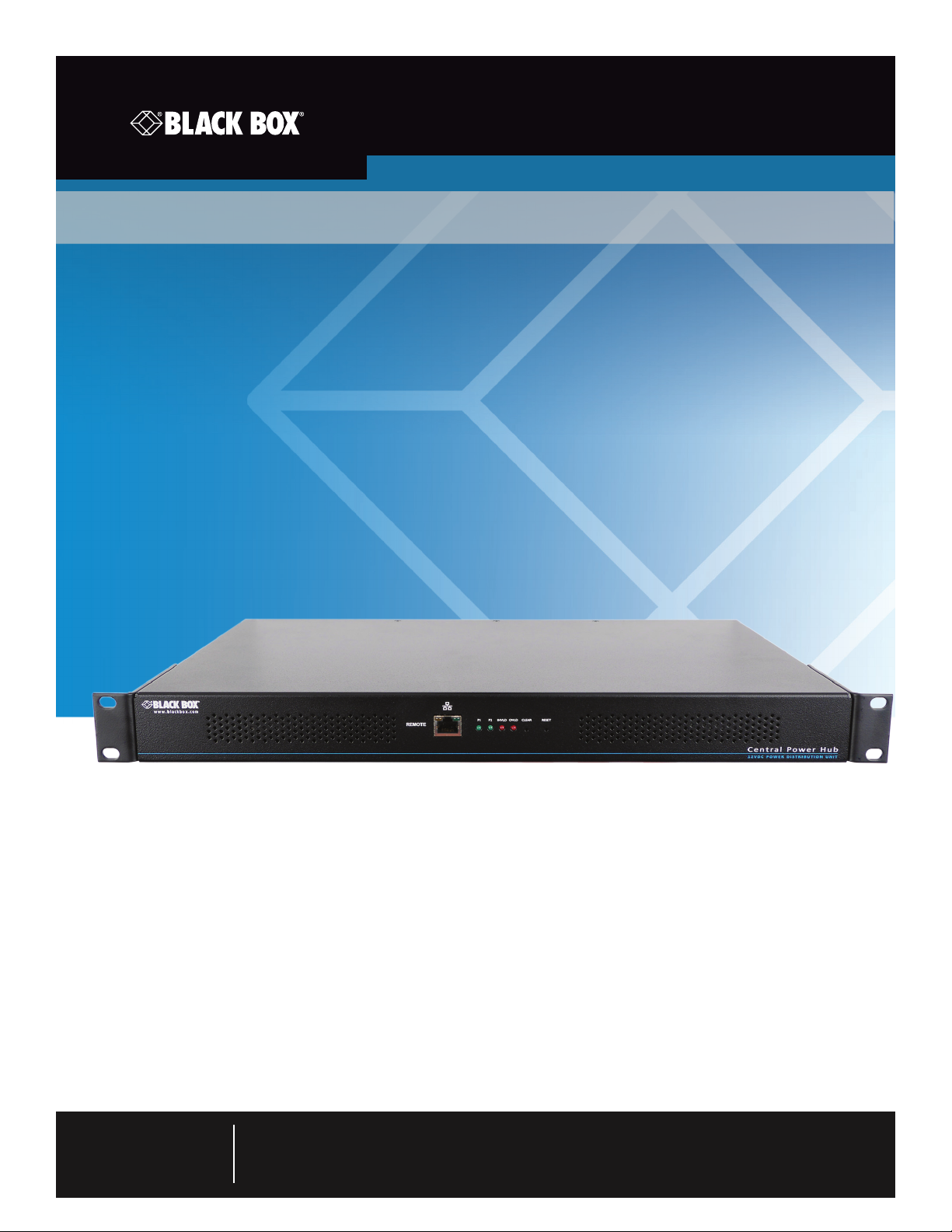
ACR1000-CPH8R ACR1000- CPH16R
ACR1000-12V5- CBL2M ACR1000-3PL-CBL2M
ACR1000-CPH-PS
Central Power Hub
Modular power source for up to sixteen devices,
with remote management and optional redundant
operation.
Customer
Support
Information
Order toll-free in the U.S. or for FREE technical support 24/7: Call 877-877-BBOX
(outside U.S. call 877-877-2269)
www.blackbox.com • [email protected]
Page 2

Central Power Hub
Trademarks Used in this Manual
Black Box and the Double Diamond logo are registered trademarks of BB Technologies, Inc.
Any other trademarks mentioned in this manual are acknowledged to be the property of the trademark owners.
Page 2
We‘re here to help! If you have any questions about your application
or our products, contact Black Box Tech Support at 877-877-2269
or go to blackbox.com and click on “Talk to Black Box.”
You’ll be live with one of our technical experts in less than 60 seconds.
877-877-2269 | blackbox.com
Page 3

FCC and IC RFI Statements
Federal Communications Commission and Industry Canada Radio Frequency Interference
Statements
This equipment generates, uses, and can radiate radio-frequency energy, and if not installed and used properly, that is, in strict
accordance with the manufacturer’s instructions, may cause inter ference to radio communication. It has been tested and found to
comply with the limits for a Class A computing device in accordance with the specifications in Subpart B of Part 15 of FCC rules,
which are designed to provide reasonable protection against such interference when the equipment is operated in a commercial
environment. Operation of this equipment in a residential area is likely to cause interference, in which case the user at his own
expense will be required to take whatever measures may be necessary to correct the interference.
Changes or modifications not expressly approved by the party responsible for compliance could void the user’s authority to
operate the equipment.
This digital apparatus does not exceed the Class A limits for radio noise emis sion from digital apparatus set out in the Radio
Interference Regulation of Industry Canada.
Le présent appareil numérique n’émet pas de bruits radioélectriques dépassant les limites applicables aux appareils numériques de
la classe A prescrites dans le Règlement sur le brouillage radioélectrique publié par Industrie Canada.
877-877-2269 | blackbox.com
Page 3
Page 4

Central Power Hub
Instrucciones de Seguridad
(Normas Oficiales Mexicanas Electrical Safety Statement)
1. Todas las instrucciones de seguridad y operación deberán ser leídas antes de que el aparato eléctrico sea operado.
2. Las instrucciones de seguridad y operación deberán ser guardadas para referencia futura.
3. Todas las advertencias en el aparato eléctrico y en sus instrucciones de operación deben ser respetadas.
4. Todas las instrucciones de operación y uso deben ser seguidas.
5. El aparato eléctrico no deberá ser usado cerca del agua—por ejemplo, cerca de la tina de baño, lavabo, sótano mojado o cerca
de una alberca, etc.
6. El aparato eléctrico debe ser usado únicamente con carritos o pedestales que sean recomendados por el fabricante.
7. El aparato eléctrico debe ser montado a la pared o al techo sólo como sea recomendado por el fabricante.
8. Servicio—El usuario no debe intentar dar servicio al equipo eléctrico más allá a lo descrito en las instrucciones de operación.
Todo otro servicio deberá ser referido a personal de servicio calificado.
9. El aparato eléctrico debe ser situado de tal manera que su posición no interfiera su uso. La colocación del aparato eléctrico
sobre una cama, sofá, alfombra o superficie similar puede bloquea la ventilación, no se debe colocar en libreros o gabinetes
que impidan el flujo de aire por los orificios de ventilación.
10. El equipo eléctrico deber ser situado fuera del alcance de fuentes de calor como radiadores, registros de calor, estufas u otros
aparatos (incluyendo amplificadores) que producen calor.
11. El aparato eléctrico deberá ser connectado a una fuente de poder sólo del tipo descrito en el instructivo de operación, o como
se indique en el aparato.
12. Precaución debe ser tomada de tal manera que la tierra fisica y la polarización del equipo no sea eliminada.
13. Los cables de la fuente de poder deben ser guiados de tal manera que no sean pisados ni pellizcados por objetos colocados
sobre o contra ellos, poniendo particular atención a los contactos y receptáculos donde salen del aparato.
14. El equipo eléctrico debe ser limpiado únicamente de acuerdo a las recomendaciones del fabricante.
15. En caso de existir, una antena externa deberá ser localizada lejos de las lineas de energia.
16. El cable de corriente deberá ser desconectado del cuando el equipo no sea usado por un largo periodo de tiempo.
17. Cuidado debe ser tomado de tal manera que objectos liquidos no sean derramados sobre la cubierta u orificios de ventilación.
18. Servicio por personal calificado deberá ser provisto cuando:
A: El cable de poder o el contacto ha sido dañado; u
B: Objectos han caído o líquido ha sido derramado dentro del aparato; o
C: El aparato ha sido expuesto a la lluvia; o
D: El aparato parece no operar normalmente o muestra un cambio en su desempeño; o
E: El aparato ha sido tirado o su cubierta ha sido dañada.
Page 4
877-877-2269 | blackbox.com
Page 5

Table of Contents
Contents
1. Specifications .............................................................................................................................................................................. 6
1.1 Options ............................................................................................................................................................................. 6
2. Welcome .................................................................................................................................................................................... 7
2.1 Protection and control ....................................................................................................................................................... 7
2.2 5VDC converter dongles ................................................................................................................................................... 7
3. Installation .................................................................................................................................................................................. 8
3.1 Mounting converter dongles ............................................................................................................................................. 8
3.2 Connections ..................................................................................................................................................................... 9
3.3 Fitting/removing a power module ...................................................................................................................................11
3.4 Network connection ........................................................................................................................................................12
4. Configuration ............................................................................................................................................................................13
4.1. Accessing the management application ..........................................................................................................................13
4.2 The Status & Control page .............................................................................................................................................. 14
4.3 The General Configuration page .................................................................................................................................... 16
4.4 The Network Settings page .............................................................................................................................................17
4.5 The User Accounts page ................................................................................................................................................. 18
4.6 The System Operations page .......................................................................................................................................... 19
5. Operation ................................................................................................................................................................................. 21
5.1 Indicators ........................................................................................................................................................................ 21
5.2 Restoring power outputs ................................................................................................................................................ 22
5.3 Resetting the Central Power Hub .................................................................................................................................... 23
Appendix A. Safety Information ................................................................................................................................................... 24
877-877-2269 | blackbox.com
Page 5
Page 6

Central Power Hub
1. Specifications
Approvals: CE, FCC
Operating Temperature: 32 to 104°F (0 to 40°C)
1.1 Options
The following options are available:
• Central power hub unit with 8 output ports Part number: ACR1000-CPH8R
• Central power hub unit with 16 output ports Part number: ACR1000-CPH16R
• 5VDC converter dongle with 6.5' (2m) lead Part number: ACR1000-12V5-CBL2M
• 12VDC link cable 6.5' (2m) Part number: ACR1000-3PL-CBL2M
• Secondary power module Part number: ACR1000-CPH-PS
Page 6
877-877-2269 | blackbox.com
Page 7
2. Welcome
Thank you for choosing the Black Box Central Power Hub.
In tune with your network, as KVM systems expand so
too do their requirements for the reliable supply of
power. While individual Black Box power adaptors perform well, as devices proliferate they can become
unwieldy and difficult to manage. Central Power Hub
provides the next step in terms of efficiency, reliability
and power management.
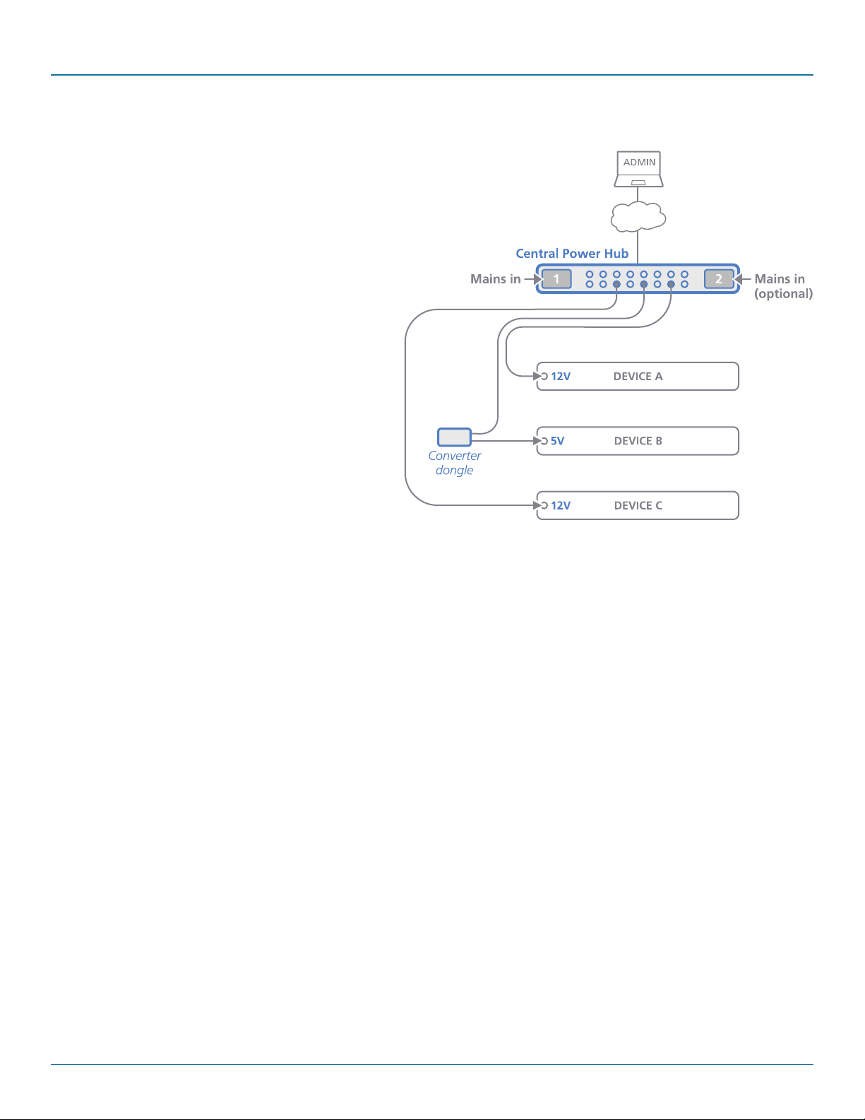
The heart of the Central Power Hub system is a modular
chassis which occupies a 1U 19” rack slot. Arranged
along its rear panel are eight or sixteen low voltage output ports. These ports are then linked via cables and/or
Converter dongles to the devices that require power. Each
output has a nominal power rating of 20W.
The overall power is generated within the main chassis by
either one or two plug-in 460W power modules. Adding
the optional second power module provides redundancy
for mission critical installations. During normal operation,
the overall load is shared between the twin power modules, with the full load transferring instantly to one if the
mains supply to the other should fail.
Chapter 2: Overview
2.1 Protection and control
Power integrity, safety and management are core elements of the Central Power Hub system. The main chassis features a central
microprocessor which manages all aspects of Central Power Hub operation. At start up it checks the validity of the single (or dual)
power module(s) and then enables them. It then energizes each of the power ports in a carefully coordinated sequence to reduce
the instantaneous load on the power module(s). After start up, each power port is carefully monitored to ensure safety protection
while also maintaining power consistency to the multiple devices:
• Electronic short protection - If an overload or short circuit occurs on any output, the power is limited to a safe value (by current pulsing) until the microprocessor recognizes the overload condition and trips the output – this happens approximately one
second after the fault happens. Once this occurs, you will need to correct the source of the short circuit and then reinstate the
output either via the front panel CLEAR button or the management application. The other power output ports will remain
unaffected during this period.
• 5V overload protection - Where an optional converter dongle is used to supply a 5V device, an extra layer of vigilance is
brought into play. If the load on a dongle exceeds approximately 5.5A, then an internal circuit will trip to protect the power
modules and the cabling. Once the cause is dealt with, a simple toggling of the power port will restore output.
• Limited power source (LPS) - Further automated protection circuits within the Central Power Hub unit ensure that it fully
complies with the IEC60950-1 regulation to operate as a Limited Power Source.
The modular 460W power modules are unique; the central microprocessor circuit reads the unique code from a register in each
power module and will only enable them once the correct code is received.
Available anywhere, via the in-built Ethernet port, a browser-based management application allows authorized admin users to
monitor and control the power module(s) and all of the individual power output ports.
2.2 5VDC converter dongles
Each power output port operates at 12VDC. For devices that use 12VDC, a simple connection cable (ACR1000-3PL-CBL2M) is all
that’s required to link them to each power port. However, numerous Black Box devices operate at a lower voltage of 5VDC and
these each require the use of a converter dongle (ACR1000-12V5-CBL2M) to take the place of the simple connection cable.
877-877-2269 | blackbox.com
Page 7
Page 8
Central Power Hub
3. Installation
Please consider the following important points when planning the position of the Central Power Hub unit:
• TheCentralPowerHubmainchassisoccupiesasingle1U(19”)rackslotandrequireseitheroneortwo(whentheredundancy
option is used) mains inputs.
• Fordevicesthatrequirea12VDCsupply,a2mlinkcable(ACR1000-3PL-CBL2M) is required.
• Fordevicesthatrequirea5VDCsupply,asmallConverterdongle(ACR1000-12V5-CBL2M)isrequiredtobepositionedcloseto
the device(s) being powered. See below for details.
• Consult the precautions listed within the Safety information section.
3.1 Mounting converter dongles
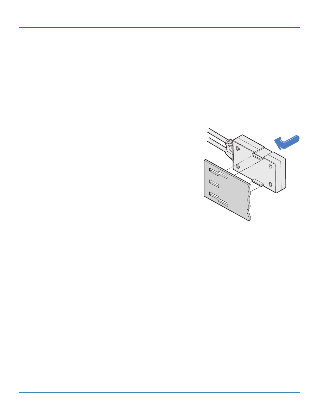
For each device that requires a 5VDC supply (12VDC devices require only a simple cable), a Converter dongle is required. Each converter dongle must be placed
in close proximity to the device. To assist with mounting dongles in congested
spaces, an optional elongated rack bracket is available for ServSwitch Agility
units that allows each dongle to be positioned just behind the device that it is
powering.
Insert the tabs of the dongle through the wider spaced holes of the rack bracket
and then slide the dongle back to lock it in place.
Note: The indentations on the side of the converter dongle allow it to be fixed
to other surfaces using a single plastic cable tie.
Page 8
877-877-2269 | blackbox.com
Page 9
3.2 Connections
The multiple output ports of the Central Power Hub each provide power at 12VDC; when
powering a 12VDC device, you merely need to use a basic cable (part number: ACR10003PL-CBL2M). However, if you need to power a 5VDC device, you must use a converter dongle (part number: ACR1000-12V5-CBL2M).
3.2.1 Connecting a 12V device
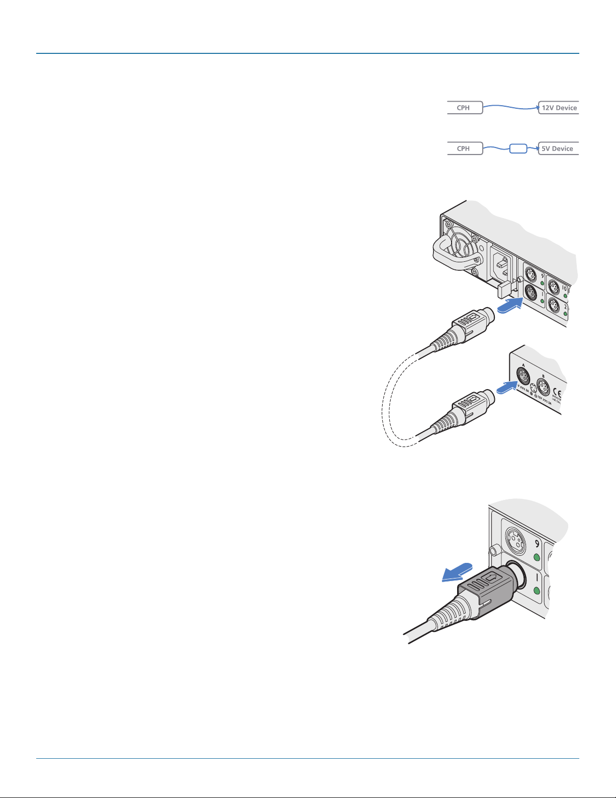
Devices that require a 12VDC supply can be connected directly to a power
port using a simple link cable.
1 Connect the locking 3-pin plug at one end of the ACR1000-3PL-CBL2M
cable to the power input socket of the device - the lead is 2m (6.5 feet) in
length.
2 Connect the locking 3-pin plug at the other end of the cable to one of the
power output sockets on the rear panel of the Central Power Hub main
chassis.
Chapter 3: Installation
ACR1000-3PL-CBL 2M link cable
ACR1000-12V5-CBL2M
link cable
ACR1000-3PL-CBL2M
link cable
3.2.2 Disconnecting a 3-pin locking plug
1 Use the management application to remove power from the required power outlet
- the green indicator must be off.
2 Grasp the outer body of the 3-pin plug.
3 Gently pull back the body of the outer plug. As the body of the plug slides back, it
will release from the socket and you can fully withdraw the whole plug.
Gently pull back
the plug outer
body to release
the lock
877-877-2269 | blackbox.com
Page 9
Page 10
Central Power Hub
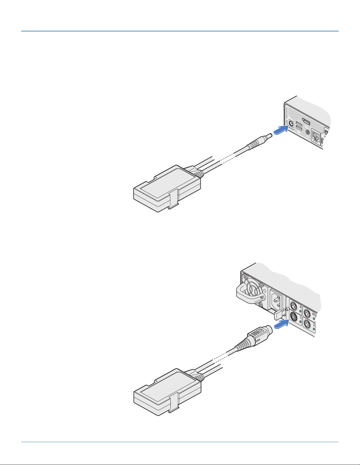
3.2.3 Connecting a 5V device
Devices that require a 5VDC supply require the use of a Converter dongle to form the link between the Central Power Hub port
and the device, while also transforming the voltage level. Each converter dongle has two leads: a 2.5mm power jack and a locking Kycon® 3-pin plug.
1 Mount the converter dongle close to the device that will be pow-
ered. An optional elongated rack bracket is available to allow the
dongle to be mounted immediately behind the device.
2 Connect the 2.5mm power jack of the dongle to the power
input socket of the device - the lead is 250mm (9.8”) in length.
Connect the
converter dongle
2.5mm jack to
the power input
of the device
ACR1000-12V5-CBL2M - converter dongle with 2m cable
3 Connect the locking 3-pin plug to one of the power output sockets on the
rear panel of the Central Power Hub main chassis - the lead is 2m (6.5 feet)
in length.
Connect the
converter dongle
locking 3-pin
plug to one
of the power
outlets
Page 10
877-877-2269 | blackbox.com
Page 11
Chapter 3: Installation
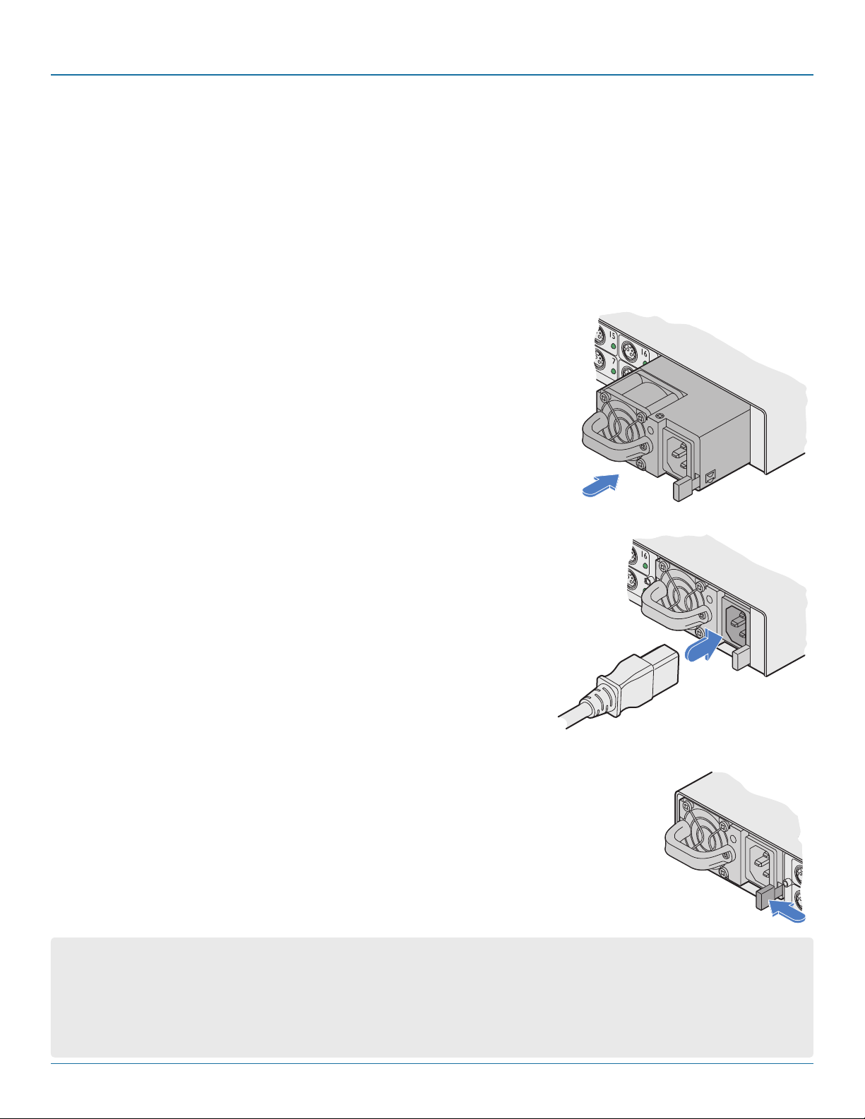
3.3 Fitting/removing a power module
The Central Power Hub main chassis can accommodate two power modules, although operation is perfectly possible with just
one module fitted. The addition of a second module provides redundancy for critical installations.
IMPORTANT: To ensure correct and reliable operation, only approved power modules may be used with the Central
Power Hub. Upon startup, each inserted power module is interrogated by the Central Power Hub and only those that
present the correct identity code will be energized. If a non-authorized power module is inserted, the INVLD indicator will illuminate and the corresponding P1 or P2 indicator (as well as the indicator on the power module itself) will
flash.
Note: Module bay 1 is on the left as you view the rear of the Central Power Hub chassis, module bay 2 is on the right.
3.3.1 To fit a power module
Note: Power modules are hot-pluggable (i.e. while power is applied to the other module), be sure to observe safe working practices and anti-static precautions when fitting a
module to a working Central Power Hub chassis.
1 If a blanking plate is fitted, remove it to reveal the power module bay.
2 Observing suitable anti-static precautions, remove the new power module from its
packing.
3 Carefully slide the power module into the vacant bay until the locking clip ‘clicks’ to
hold the module in place.
4 Insert an IEC power cord into the socket on the module and apply power to
the module.
3.3.2 To remove a power module
Note: Power modules are hot-pluggable (i.e. while power is applied to the other module), be sure to
observe safe working practices and anti-static precautions when removing a module from a working
Central Power Hub chassis.
1 Isolate power from the module to be removed and disconnect the IEC power cord.
2 Push the locking lever to the left so that the module un-clips and use the handle to carefully pull
the module out of the bay.
3 If no replacement module is to be used, fit a blanking plate to cover the vacant bay.
IMPORTANT: Please read and adhere to the electrical safety information given within the Safety information section of this
guide. In particular, do not use an unearthed power socket or extension cable.
Note: Various items within the Central Power Hub casing generate heat when in operation and will become warm to the touch.
Ensure that air can circulate freely at the rear of the enclose, particularly by the power module cooling fans. Do not operate the
equipment in ambient temperatures exceeding 50 degrees Centigrade. Do not place the products in contact with equipment
whose surface temperature exceeds 50 degrees Centigrade.
877-877-2269 | blackbox.com
Pa g e 11
Page 12
Central Power Hub
3.4 Network connection
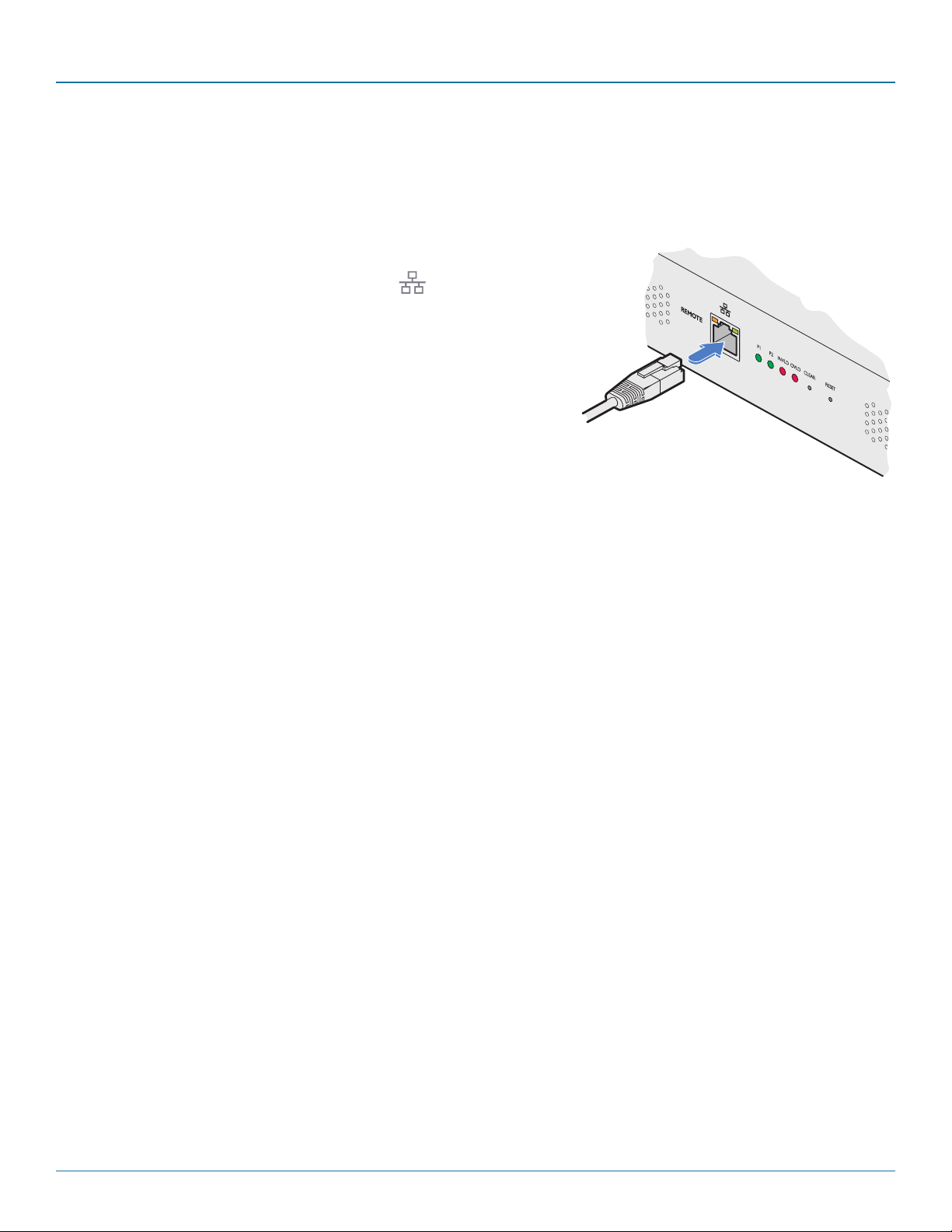
The Central Power Hub allows remote monitoring and control via a standard network connection.
Note: The patch cable used to link with the Central Power Hub must be screened to the S/FTP level.
3.4.1 To connect to a network
1 Use a screened patch cable (cross-over or straight connections are both sup-
ported) to link the Ethernet 10/100 network port ( ) on the front panel of
the main chassis switch to a network switch.
S/FTP screened
patch cable link
to a network
switch
Page 12
877-877-2269 | blackbox.com
Page 13
Chapter 4: Configuration
4. Configuration
4.1. Accessing the management application
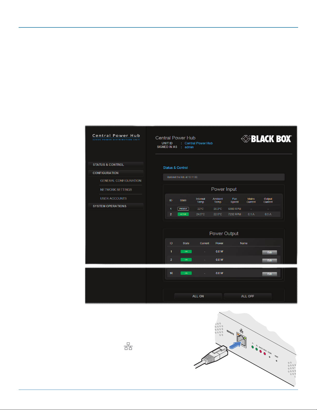
Each Central Power Hub is configured via its network connections using an intuitive browser-based application. This secure, password protected application is accessible by any authorized admin user, located anywhere.
4.1.1 To access the management application
1 Use a computer that is directly or indirectly (i.e. via a network switch) connected to the Central Power Hub unit. If you need to
make a temporary connection, see below.
2 Run a web browser on your computer and enter the IP address of the Central Power Hub. The default IP address setting is:
192.16 8 .1. 2 2
3 If requested, enter your
username and password
to log on.
Note: The default username
and password are ‘admin’
and ‘password’ respectively.
The opening page of the
management application
should be displayed:
4.1.2 To temporarily connect a computer to the network port
1 If you need to make a temporary connection for configuration purposes, use
a standard patch cable (cross-over or straight connections are both supported) to link the Ethernet 10/100 network port ( ) on the front panel of the
main chassis to your computer.
Note: The patch cable used to link with the Central Power Hub must be
screened to the S/FTP level.
877-877-2269 | blackbox.com
S/FTP screened
patch cable link to
your computer
Page 13
Page 14
Central Power Hub
4.2 The Status & Control page
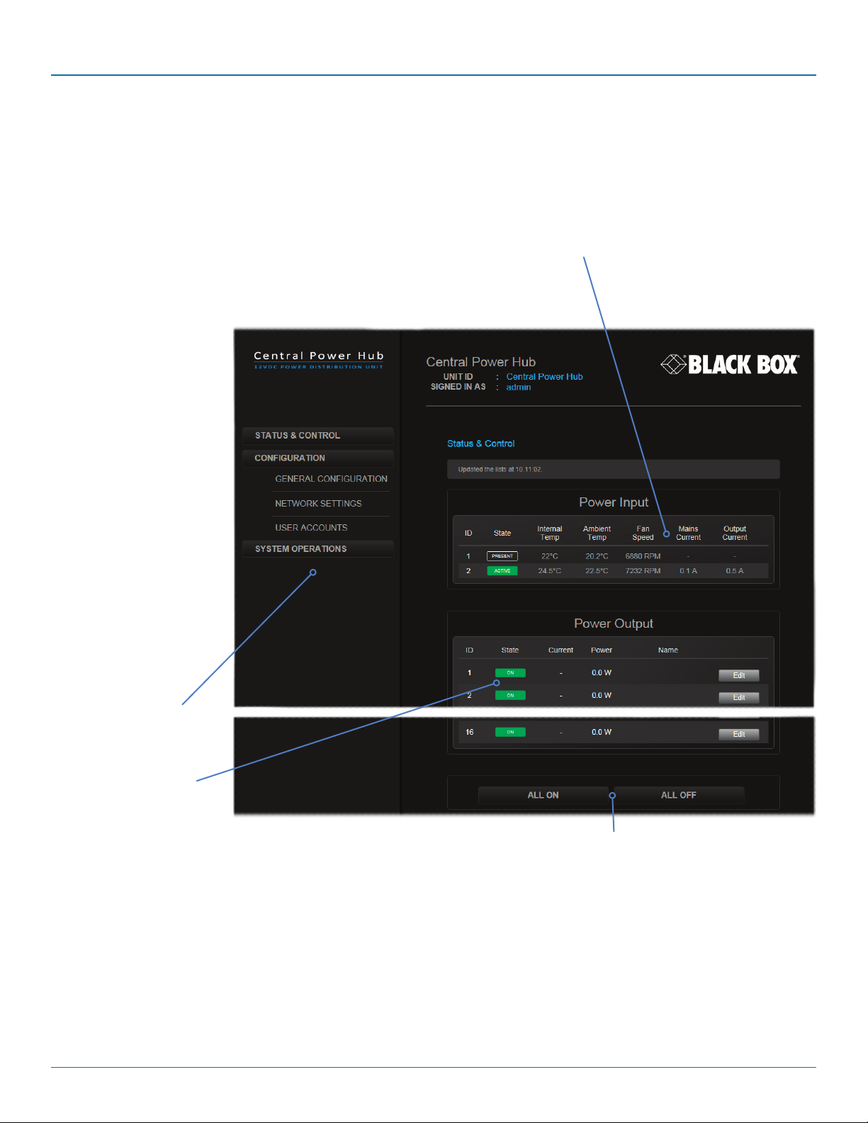
This opening page of the manager application provides a useful real time overview of the power input and output status. Using
this page you can quickly ascertain the key metrics related to the power modules (e.g. temperatures, fan speeds, mains and output currents) as well as each output port. Additionally, you can monitor, name and control each output port individually.
Key metrics for the single, or dual, power module(s),
including the temperatures, cooling fan speeds, mains
input and low voltage output currents.
Click the required menu
item to reveal the available
page choices.
Status details for all power
output ports. To change
the output status, click
the ON / OFF button. To
rename a port, click the
Edit button.
Page 14
Use these buttons to affect all power output ports
collectively. When the ALL ON button is pressed, the
individual ports will be energized in a staggered
sequence determined by the Channel interval setting
in the General configuration page.
877-877-2269 | blackbox.com
Page 15

Chapter 4: Configuration
4.2.1 To change the status of a single power output port
1 Locate the required power output port entry by its ID number or Name (if given).
2 Click the corresponding State button to change the output port from ON to OFF, or vice versa.
4.2.2 To change the status of all power output ports
1 Locate the ALL ON and ALL OFF buttons below the Power Output section. As appropriate, click either the ALL ON or ALL OFF
button.
2 Click OK to confirm your choice in the subsequent popup.
Note: When the ALL ON button is pressed, the individual ports will be energized in a staggered sequence determined by the
Channel interval setting in the General configuration page.
4.2.3 To name a power output port
1 Locate the required power output port entry.
2 Click the corresponding Edit button. A cursor will appear within the Name field.
3 Enter the required name for the power output port and click the Update button.
Note: Name fields accept ASCII characters only. UTF-8 characters are not supported.
877-877-2269 | blackbox.com
Page 15
Page 16
Central Power Hub
4.3 The General Configuration page
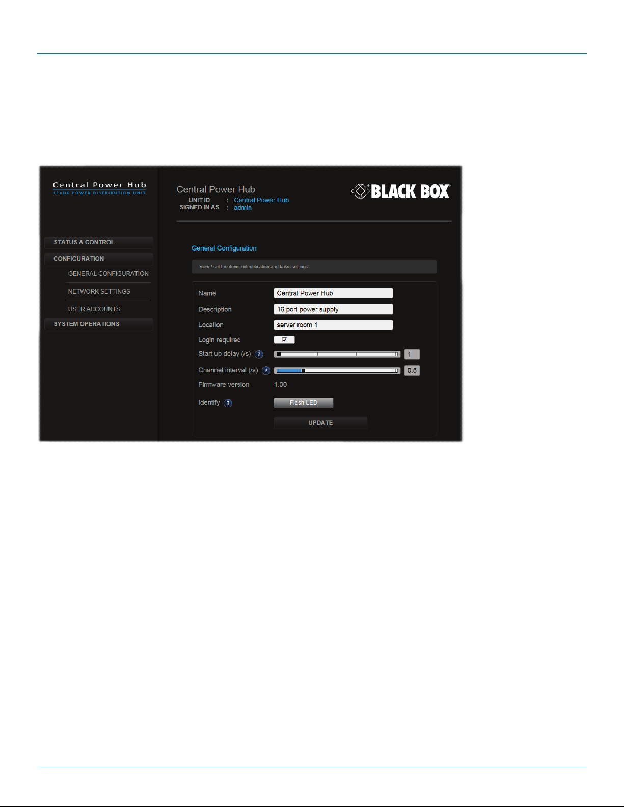
This page contains various important settings related to Central Power Hub labelling, login, identity and startup.
IMPORTANT: When you make a change to any setting, don’t forget to click the Update button to save the change.
Note: The Name, Description and Location fields accept ASCII characters only. UTF-8 characters are not supported.
• Name - the primary identity of this Central Power Hub unit.
• Description - a further opportunity to add more information about the Central Power Hub unit.
• Location - a useful feature if you have multiple Central Power Hub units distributed around.
• Login required - when ticked, all users will be requested to enter a valid username and password prior to access being
granted.
• Start up delay - this setting determines the time delay in seconds that should elapse, after mains power is first applied to the
unit, before the power modules apply their full supply to the Central Power Hub chassis. This feature is useful when multiple
Central Power Hub units are fed from the same mains power feed. By staggering the switch on points of the various units,
the impact of multiple switched mode power supplies and their initial in-rush currents are greatly reduced. Values range
from 0 to 10 seconds.
• Channel interval - this setting determines the time delay, in seconds, that should elapse between each power output port
being energized. This performs an important task in preventing initial power overloads as each device reaches its quiescent
state. Values range from 0.1 to 2 seconds.
• Firmware version - displays the current version of internal software used within the Central Power Hub logic system.
• Identity - used to visually identify the Central Power Hub unit when multiple units are installed together. Click the Flash LED
button to flash the front panel LED indicators, as follows:
• Click the button once to flash the LED indicators five times.
• Click the button twice to flash the LED indicators indefinitely.
• Click the button a third time to stop the flashing.
Page 16
877-877-2269 | blackbox.com
Page 17
Chapter 4: Configuration
4.4 The Network Settings page
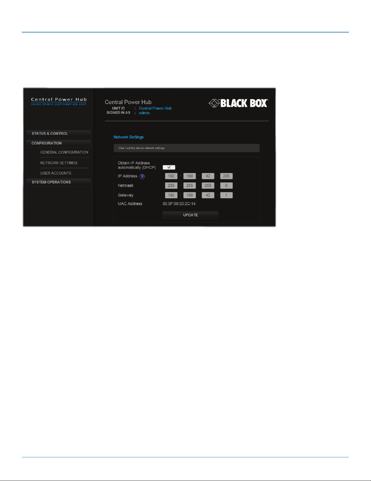
This determines the network settings used by the Central Power Hub unit.
IMPORTANT: When you make a change to any setting, don’t forget to click the Update button to save the change.
• Obtain IP Address automatically - when ticked, the Central Power Hub will use DHCP (Dynamic Host Configuration Protocol)
to automatically determine all network settings (and all other options in this page will be grayed out). When unticked, use
the other options to configure the network settings manually.
• IP Address - set the IP address for the Central Power Hub.
• Netmask - set a subnet mask to accompany the IP address.
• Gateway - optionally define a suitable address for a gateway device (only needed if external access to Central Power Hub is
required).
• MAC Address - displays the unique (and fixed) MAC address for the Central Power Hub.
877-877-2269 | blackbox.com
Page 17
Page 18
Central Power Hub
4.5 The User Accounts page
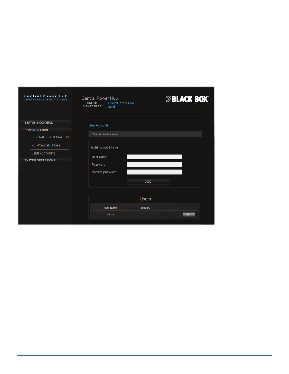
This page allows you to administer the details for users of the Central Power Hub unit. By its nature Central Power Hub is not an
end user access product, so every authorized user is considered as an admin with the same rights. Extra users can be added and
deleted, however, the main ‘admin’ entry cannot be deleted or renamed, only its password can be changed.
Note: The Central Power Hub will only request Login details if the ‘Login required’ option within the General configuration
page is ticked.
4.5.1 To add a new user
1 Enter a User Name and Password (and then Confirm password) in the labeled fields.
Note: The User Name and Password fields accept ASCII characters only. UTF-8 characters are not supported.
2 Click the Add button. If the two password entries match, the new user details will be added to the list of Users below.
4.5.2 To edit a user
1 Locate the required entry within the Users list.
2 Click the Edit button, change the necessary details and then click the Update button.
Note: The main ‘admin’ entry name cannot be deleted or renamed, only its password can be changed.
4.5.3 To delete a user
1 Locate the required entry within the Users list.
2 Click the Delete button.
Note: The main ‘admin’ entry name cannot be deleted.
Page 18
877-877-2269 | blackbox.com
Page 19
Chapter 4: Configuration
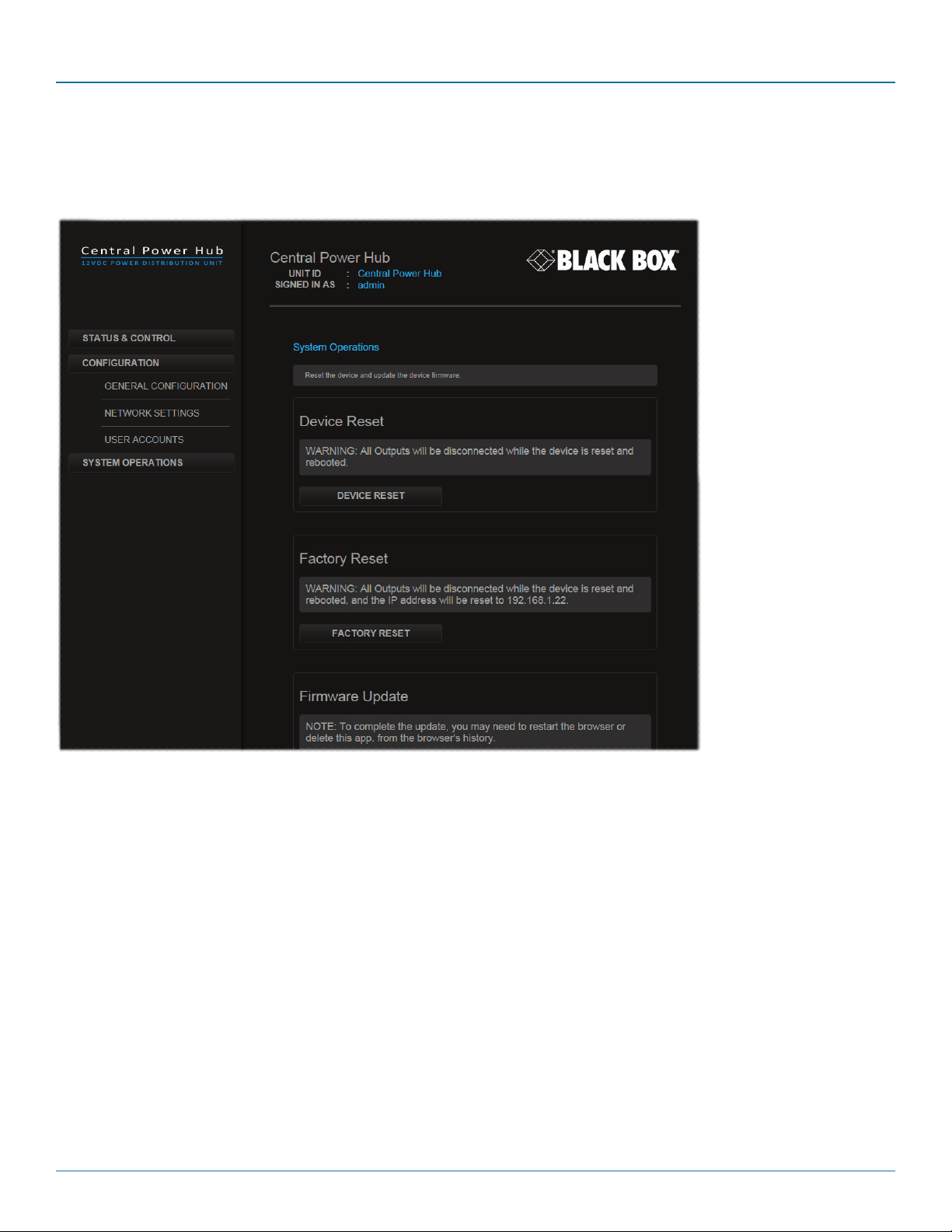
4.6 The System Operations page
This page contains various options for resetting and updating the Central Power Hub. All options given here will interrupt normal
operations and should be used with caution.
4.6.1 Device reset
This option will reset the operation of the Central Power Hub unit, equivalent to a cold reboot (as if power to it had been
removed and restored). All power outputs will be removed and then restored in a staggered manner defined by the start up delay
and Channel interval settings within the General configuration page. No configuration details will be changed but you will need to
reconnect your network link with the Central Power Hub unit.
4.6.1.1 To reset the Central Power Hub device
1 Click the Device Reset button.
2 Click OK to confirm your choice in the subsequent popup.
877-877-2269 | blackbox.com
Page 19
Page 20

Central Power Hub
4.6.2 Factory reset
This option will perform a cold reboot but will also return all configuration details to the factory settings. Note: The IP address will
be returned to 192.168.1.22 (DHCP will be disabled) and all user entries apart from the main admin will be removed. You will
need to reconnect your network link with the Central Power Hub unit.
4.6.2.1 To perform a factory reset
1 Click the Factory Reset button.
2 Click OK to confirm your choice in the subsequent popup.
4.6.3 Firmware update
This option will perform an update to the firmware contained within the logic circuitry of the Central Power Hub unit. You will
first need to download the latest firmware file for the device from Black Box technical support and ensure that it is unzipped and
accessible from the computer you are using to access the Central Power Hub unit.
4.6.3.1 To perform a firmware update
1 Click the Select Firmware File button. A file dialog will be displayed.
2 Use the file dialog to locate the new firmware file and click Open.
3 Click the Update Firmware button.
Page 20
877-877-2269 | blackbox.com
Page 21
Chapter 5: Operation
5. Operation
The Central Power Hub system is designed to be transparent in operation.
5.1 Indicators
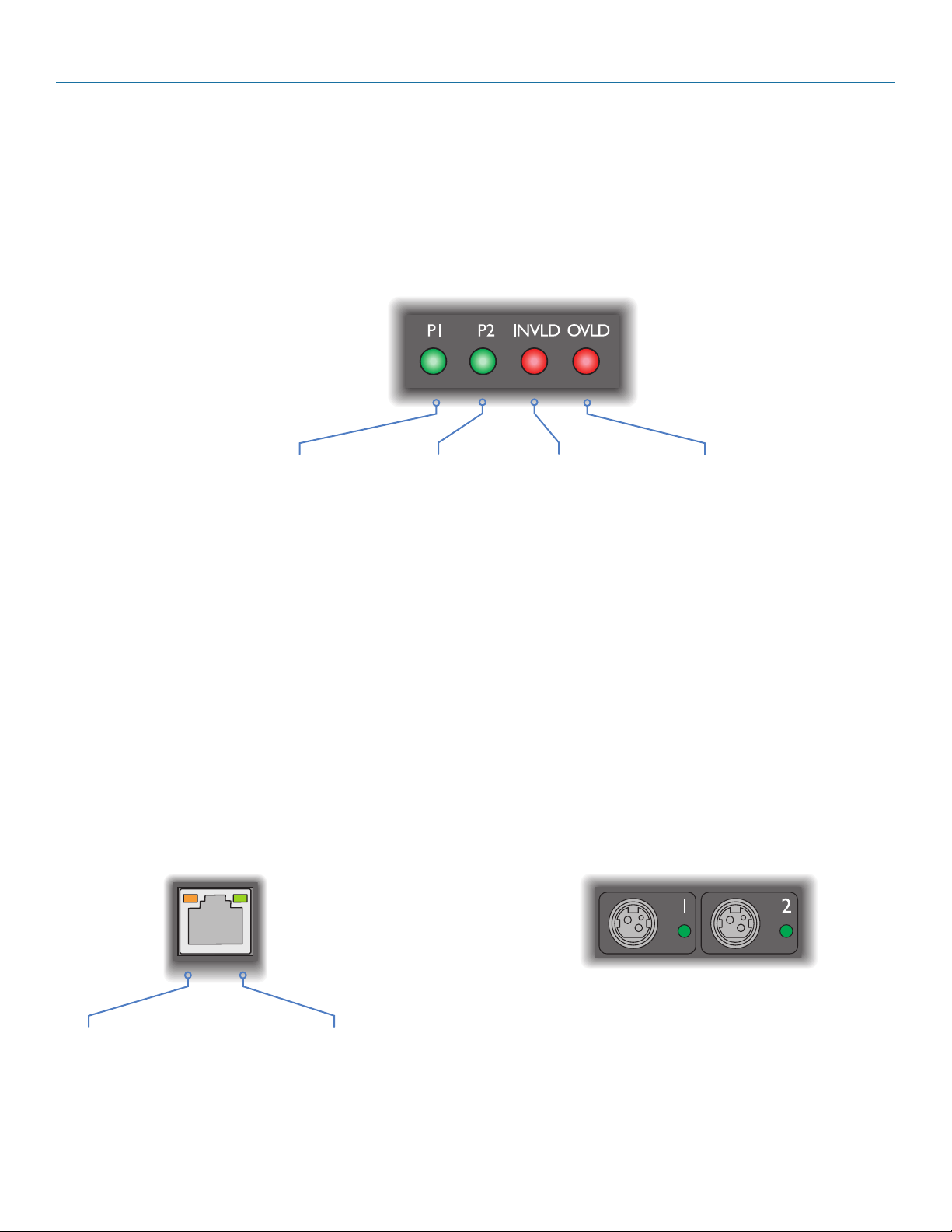
The Central Power Hub main chassis contains various indicators to provide you with status information. There are four main indicators on the front panel as well as green and amber indicators on the network port connector.
5.1.1 Red status indicators
The red status indicators on the front panel
provide various key power and operation
feedback:
P1
On: The power
module in bay 1 has
a mains input and is
operating.
Flashing: An invalid
power module has
been inserted into
bay 1.
Note: The P1 and P2 indicators mimic the
green indicators that are located on the rear of
each power module, near to their cooling fans.
5.1.2 Green and amber network status
indicators
The green and amber status indicators on the front
panel network port connector provide further status
information:
P2
On: The power
module in bay 2 has
a mains input and is
operating.
Flashing: An invalid
power module has
been inserted into
bay 2.
INVLD
Flashing: One (or
both) of the power
modules is an invalid
type.
OVLD
On: An overload condition
has been detected on one
or more of the 12V output
ports. The port will have
powered down. After
rectifying the cause, press
the recessed CLEAR button
to re-enable the port.
Note: An OVLD condition
can also be cleared by
clicking the FAULT indicator
in the management
application.
5.1.3 Green power output status
indicators
On the rear panel, each power output port has
a green status indicator:
Amber
Off: No link
On/flashing: Network link present
Green
Off: No link
On: Network link active
877-877-2269 | blackbox.com
On: Power (12VDC) is being
supplied to the adjacent port.
Page 21
Page 22

Central Power Hub
5.2 Restoring power outputs
As discussed in the Welcome section, the Central Power Hub ports are carefully monitored to ensure safety protection while also
maintaining power consistency to the multiple devices:
• Electronicshortprotection-Ifanoverloadorshortcircuitoccursonanyoutput,thepowerislimitedtoasafevalue(bycurrent
pulsing) until the microprocessor recognizes the overload condition and trips the output – this happens approximately one second after the fault happens. The resulting trip is indicated on the Central Power Hub front panel by the OVLD being on and
also within the management application (‘FAULT’ is shown next to the affected port within the Status & Control page).
• 5Voverloadprotection-ApplicableonlytooutputsthatuseoptionalConverterdongles.Whentheloadexceedsapproximately
5.5A*, a dongle will internally trip its power output. In most cases this will occur before the electronic short protection (mentioned above) reacts. In such cases, the power trip will not be reported back to the Central Power Hub unit and its output will
remain intact, although the listed current output for that port will fall to (or near) zero.
5.2.1 To restore a power output
1 Following an automatic power trip, your first task is to locate the cause of the problem. It may have been a temporary overload
issue that has subsided or something more permanent. Perform thorough checks on the implicated device and all of the power
cabling between it and the Central Power Hub.
2 Depending on where the trip was made, you will see different results:
• IftheCentralPowerHubelectronicshortprotectioncircuitresponded,thefrontpanelOVLD indicator will be lit and also the
rear panel green indicator adjacent to the affected port will be OFF. Within the Status & Control page of the manager appli-
cation, the port State will be shown as FAULT.
• Iftheconverterdongleoverloadcircuitresponded,itislikelythatthecorrespondingCentralPowerHuboutputportwillstill
be active.
3 Accordingly, your remedial actions will differ:
• WherethefaultisindicatedonthefrontpanelOVLD indicator (once you have diagnosed and corrected the cause), use a
narrow implement (e.g. straightened paperclip) to press and release the recessed front panel CLEAR button. The power output to port will be reinstated. Alternatively, within the management application (Status & Control page), click the FAULT
state shown against the affected port.
• Wherethefaultwasdetectedbyaconverterdongle,eitherusetheStatus&Controlpageofthemanagementapplication
to switch the port Off and then On; or at the Central Power Hub rear panel remove and reconnect the converter dongle
connection.
4 For a suitable period after resuming the power supply to the affected port, closely monitor the device, the Central Power Hub
and all related cabling for a reoccurrence of the same or similar problem.
* If you are using the management application to monitor supply currents, remember that due to the conversion from 12VDC to
5VDC, the values shown at the power output ports (within the app) differ from the currents flowing to the device. Roughly
speaking, 5.5A at the 5V level will be reported at the management application as 2.3A at 12V.
Page 22
877-877-2269 | blackbox.com
Page 23

Chapter 5: Operation
5.3 Resetting the Central Power Hub
If it becomes necessary to reset the entire Central Power Hub unit, this can be achieved either using the management application
(see The Systems operation page) or the recessed RESET button on the front panel. Using either method it is possible to enact a
basic reset (equivalent to removing and restoring mains power) or a full factory reset.
5.3 .1 Device reset from the front panel
This procedure will reset the operation of the Central Power Hub unit, equivalent to a cold reboot. All power outputs will be
removed and then restored in a staggered manner (as defined within the management application). No configuration details will
be changed.
• Useanarrowimplement(e.g.straightenedpaperclip)topressandreleasetherecessedfrontpanelRESETbutton.
5.3.2 Factory reset from the front panel
This procedure will perform a cold reboot but will also return all configuration details to their factory settings. Note: The IP address
will be returned to 192.168.1.22 (DHCP will be disabled) and all user entries apart from the main admin will be removed.
• Useanarrowimplement(e.g.straightenedpaperclip)topressandholdtherecessedfrontpanelRESETbuttonfor20seconds.
877-877-2269 | blackbox.com
Page 23
Page 24

Central Power Hub
Appendix A. Safety Information
• Foruseindry,oilfreeindoorenvironmentsonly.
• Donotusetolinkbetweenbuildings.
• Ensurethatthetwistedpairinterconnectcableisinstalledincompliancewithallapplicablewiringregulations.
• DonotconnecttheCATxlinkinterface(RJ45styleconnector)toanyotherequipment,particularlynetworkortelecommunica-
tions equipment.
• Warning–thepoweradaptercontainsliveparts.
• Nouserserviceablepartsarecontainedwithinthepoweradapter-donotdismantle.
• Plugthepoweradapterintoagroundedsocketoutletclosetotheunitthatitispowering.
• Replacethepoweradapterwithamanufacturerapprovedtypeonly.
• Donotusethepoweradapterifthepoweradaptercasebecomesdamaged,crackedorbrokenorifyoususpectthatitisnot
operating properly.
• Ifyouuseapowerextensioncordwiththeunits,makesurethetotalampereratingofthedevicespluggedintotheextension
cord do not exceed the cord’s ampere rating. Also, make sure that the total ampere rating of all the devices plugged into the
wall outlet does not exceed the wall outlet’s ampere rating.
• Donotattempttoservicetheunitsyourself.
• Theunitsandpowersuppliescangetwarminoperation–donotsituatetheminanenclosedspacewithoutanyventilation.
• Theunitsdonotprovidegroundisolationandshouldnotbeusedforanyapplicationsthatrequiregroundisolationorgalvanic
isolation.
Page 24
877-877-2269 | blackbox.com
Page 25

Appendices
877-877-2269 | blackbox.com
Page 25
Page 26

Black Box Tech Support: FREE! Live. 24/7.
®
®
Tech support the
way it should be.
Great tech support is just 60 seconds away at 877-877-2269 or blackbox.com.
About Black Box
Black Box provides an extensive range of networking and infrastructure products. You’ll find everything from cabinets and racks
and power and surge protection products to media converters and Ethernet switches all supported by free, live 24/7 Tech support
available in 60 seconds or less.
© Copyright 2020. Black Box Corporation. All rights reserved. Black Box® and the Double Diamond logo are registered trademarks of BB Technologies, Inc.
Any third-party trademarks appearing in this manual are acknowledged to be the property of their respective owners.
ACR1000, rev. 1.2
877-877-2269 | blackbox.com
 Loading...