

Black Box ACR1000A-CTLR2-24, ACR1000A-CTLR2-48, ACR1000A-CTLR2-96, ACR1000A-CTLR2-192, ACR1000A-CTLR2-288 User guide
...Page 1

USER GUIDE
ACR1000A-CTLR2-24 ACR1000A-CTLR2-48 ACR1000A-CTLR2-96
ACR1000A-CTLR2-192 ACR1000A-CTLR2-288 ACR1000A-CTLR2-ULT
iPATH
AGILITY
CONTROLLER
24/7 TECHNICAL SUPPORT AT 1.877.877.2269 OR VISIT BLACKBOX.COM
Page 2

TRADEMARKS USED IN THIS MANUAL
Black Box and the Double Diamond logo are registered trademarks of BB Technologies, Inc.
Any other trademarks mentioned in this manual are acknowledged to be the property of the trademark owners.
NEED HELP?
LEAVE T HE TEC H TO US
LIVE 24/7
TECHNICAL
SUPPORT
1.877.877.2269
We‘re here to help! If you have any questions about your application
or our products, contact Black Box Tech Support at 877-877-2269
or go to blackbox.com and click on “Talk to Black Box.”
You’ll be live with one of our technical experts in less than 60 seconds.
2
1. 8 7 7. 87 7. 226 9 BLACKBOX.COM
Page 3

NEED HELP?
LEAVE T HE TEC H TO US
LIVE 24/7
TECHNICAL
SUPPORT
1.877.877.2269
FEDERAL COMMUNICATIONS COMMISSION AND INDUSTRY CANADA RADIO FREQUENCY INTERFERENCE
STATEMENTS
This equipment generates, uses, and can radiate radio-frequency energy, and if not installed and used properly, that is, in strict
accordance with the manufacturer’s instructions, may cause inter ference to radio communication. It has been tested and
found to comply with the limits for a Class A computing device in accordance with the specifications in Subpart B of Part 15 of
FCC rules, which are designed to provide reasonable protection against such interference when the equipment is operated in a
commercial environment. Operation of this equipment in a residential area is likely to cause interference, in which case the user
at his own expense will be required to take whatever measures may be necessary to correct the interference.
Changes or modifications not expressly approved by the party responsible for compliance could void the user’s authority to
operate the equipment.
This digital apparatus does not exceed the Class A limits for radio noise emis sion from digital apparatus set out in the Radio
Interference Regulation of Industry Canada.
Le présent appareil numérique n’émet pas de bruits radioélectriques dépassant les limites applicables aux appareils numériques
de la classe A prescrites dans le Règlement sur le brouillage radioélectrique publié par Industrie Canada.
Disclaimer:
Black Box Network Services shall not be liable for damages of any kind, including, but not limited to, punitive, consequential or
cost of cover damages, resulting from any errors in the product information or specifications set forth in this document and Black
Box Network Services may revise this document at any time without notice.
1. 8 7 7. 87 7. 226 9 BLACKBOX.COM
3
Page 4

NEED HELP?
LEAVE T HE TEC H TO US
LIVE 24/7
TECHNICAL
SUPPORT
1.877.877.2269
INSTRUCCIONES DE SEGURIDAD
(NORMAS OFICIALES MEXICANAS ELECTRICAL SAFETY STATEMENT)
1. Todas las instrucciones de seguridad y operación deberán ser leídas antes de que el aparato eléctrico sea operado.
2. Las instrucciones de seguridad y operación deberán ser guardadas para referencia futura.
3. Todas las advertencias en el aparato eléctrico y en sus instrucciones de operación deben ser respetadas.
4. Todas las instrucciones de operación y uso deben ser seguidas.
5. El aparato eléctrico no deberá ser usado cerca del agua—por ejemplo, cerca de la tina de baño, lavabo, sótano mojado o cerca
de una alberca, etc.
6. El aparato eléctrico debe ser usado únicamente con carritos o pedestales que sean recomendados por el fabricante.
7. El aparato eléctrico debe ser montado a la pared o al techo sólo como sea recomendado por el fabricante.
8. Servicio—El usuario no debe intentar dar servicio al equipo eléctrico más allá a lo descrito en las instrucciones de operación.
Todo otro servicio deberá ser referido a personal de servicio calificado.
9. El aparato eléctrico debe ser situado de tal manera que su posición no interfiera su uso. La colocación del aparato eléctrico
sobre una cama, sofá, alfombra o superficie similar puede bloquea la ventilación, no se debe colocar en libreros o gabinetes
que impidan el flujo de aire por los orificios de ventilación.
10. El equipo eléctrico deber ser situado fuera del alcance de fuentes de calor como radiadores, registros de calor, estufas u otros
aparatos (incluyendo amplificadores) que producen calor.
11. El aparato eléctrico deberá ser connectado a una fuente de poder sólo del tipo descrito en el instructivo de operación, o como
se indique en el aparato.
12. Precaución debe ser tomada de tal manera que la tierra fisica y la polarización del equipo no sea eliminada.
13. Los cables de la fuente de poder deben ser guiados de tal manera que no sean pisados ni pellizcados por objetos colocados
sobre o contra ellos, poniendo particular atención a los contactos y receptáculos donde salen del aparato.
14. El equipo eléctrico debe ser limpiado únicamente de acuerdo a las recomendaciones del fabricante.
15. En caso de existir, una antena externa deberá ser localizada lejos de las lineas de energia.
16. El cable de corriente deberá ser desconectado del cuando el equipo no sea usado por un largo periodo de tiempo.
17. Cuidado debe ser tomado de tal manera que objectos liquidos no sean derramados sobre la cubierta u orificios de ventilación.
18. Servicio por personal calificado deberá ser provisto cuando:
A: El cable de poder o el contacto ha sido dañado; u
B: Objectos han caído o líquido ha sido derramado dentro del aparato; o
C: El aparato ha sido expuesto a la lluvia; o
D: El aparato parece no operar normalmente o muestra un cambio en su desempeño; o
E: El aparato ha sido tirado o su cubierta ha sido dañada.
4
1. 8 7 7. 87 7. 226 9 BLACKBOX.COM
Page 5

NEED HELP?
LEAVE T HE TEC H TO US
LIVE 24/7
CONTENTS
TECHNICAL
SUPPORT
1.877.877.2269
CONTENTS ................................................................................................................................. 5
CHAPTER 1: SPECIFICATIONS ..................................................................................................... 7
CHAPTER 2: WELCOME .............................................................................................................. 7
Local feed through...................................................................................................................................................................................... 9
iPATH basics ............................................................................................................................................................................................. 10
CHAPTER 3: INSTALLATION ..................................................................................................... 12
Connections .............................................................................................................................................................................................. 12
Model specific requirements ................................................................................................................................................................... 14
Tips for a successful implementation .................................................................................................................................................... 14
Mounting the iPATH Agility Controller .................................................................................................................................................... 15
CHAPTER 4: CONFIGURATION .................................................................................................. 16
Supported browsers ................................................................................................................................................................................. 16
Login for admin users ..............................................................................................................................................................................16
Important first configuration steps ........................................................................................................................................................17
Adding Agility units .................................................................................................................................................................................18
If an Agility unit is not located ................................................................................................................................................................. 18
Agility manual factory reset..................................................................................................................................................................... 19
Front panel indications ............................................................................................................................................................................20
The Dashboard tab ................................................................................................................................................................................... 21
Upgrading Agility firmware globally ........................................................................................................................................................37
Upgrading (or downgrading) iPATH firmware ........................................................................................................................................38
Enabling Remote Support ........................................................................................................................................................................ 40
Web Interface Access ............................................................................................................................................................................... 41
Troubleshooting ........................................................................................................................................................................................41
The Channels tab ......................................................................................................................................................................................42
The Remotes tab .......................................................................................................................................................................................46
The Locals tab ..........................................................................................................................................................................................53
The Servers tab ......................................................................................................................................................................................... 57
The Users tab ............................................................................................................................................................................................ 59
The Presets tab .........................................................................................................................................................................................63
The Statistics tab .....................................................................................................................................................................................66
1. 8 7 7. 87 7. 226 9 BLACKBOX.COM
5
Page 6

NEED HELP?
LEAVE T HE TEC H TO US
LIVE 24/7
TECHNICAL
SUPPORT
1.877.877.2269
CHAPTER 5: OPERATION .......................................................................................................... 67
Logging in ..................................................................................................................................................................................................67
Using the Remote OSD feature ................................................................................................................................................................70
CHAPTER 6: FURTHER INFORMATION ...................................................................................... 72
Appendix A. Tips for success when networking Agility units .............................................................................................................. 73
Appendix B. Troubleshooting ..................................................................................................................................................................76
Appendix C. Redundant servers: Setting up and swapping out ...........................................................................................................79
Appendix D. Upgrade Licence .................................................................................................................................................................82
Appendix E. Glossary ...............................................................................................................................................................................83
Appendix F. iPATH API ..............................................................................................................................................................................87
Appendix G. DHCP server requirements for Agility support ............................................................................................................... 110
Appendix H. Using DHCP Option 125 .....................................................................................................................................................112
Safety information .................................................................................................................................................................................. 114
6
1. 8 7 7. 87 7. 226 9 BLACKBOX.COM
Page 7
CHAPTER 1: SPECIFICATIONS
Approvals: CE, FCC
Hardware: Industrial specification server with solid state memory
Software: Closed system with bespoke application preloaded
Physical design: WxHxD: 8.5” x 1.6” x 8.3”
215mm x 40mm x 210mm
Weight: 4 lbs (1.8kg)
Operating Temperature: 32 to 104°F (0 to 40°C)
Relative Humidity: 10-90% non-condensing
Permitted Altitude: <2000m
Power: DC jack (power adapter included)
Input: 100–240 VAC, 50/60 Hz 20W
Output: 12VDC, 5.0A
Use only Black Box approved replacement power adapters.
NEED HELP?
LEAVE T HE TEC H TO US
LIVE 24/7
TECHNICAL
SUPPORT
1.877.877.2269
CHAPTER 2: WELCOME
Agility local and remote units allow multiple remote users to access host computers in a very flexible manner. Such flexibility
requires management and coordination – that is where iPATH Agility Controller becomes vital.
iPATH is designed to promote the most efficient use of Agility units by allowing central control over any number of local and remote
units. Using the intuitive iPATH web-based interface, one or more administrators can manage potentially thousands of users who
are interacting with an almost unlimited number of devices.
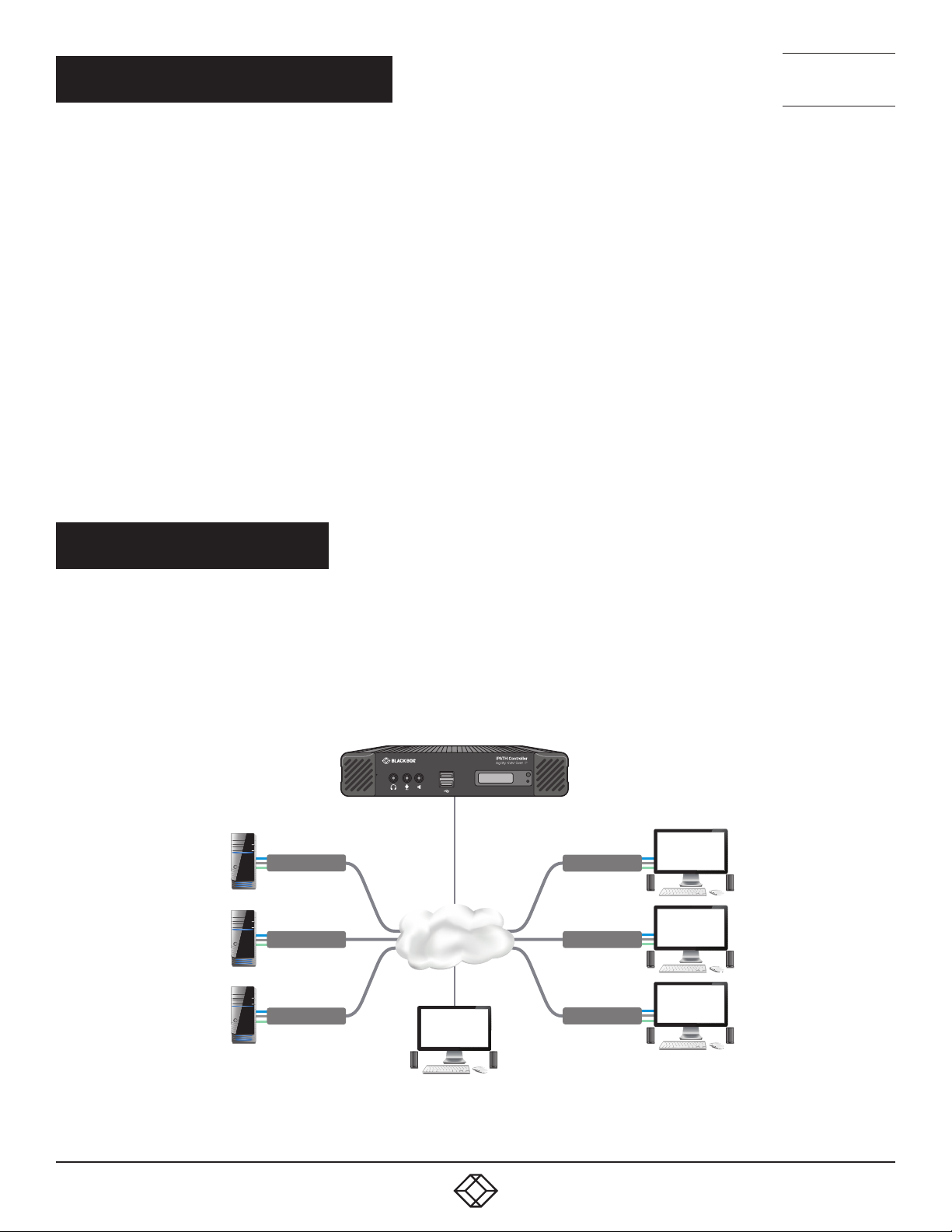
iPATH operates as a self-contained compact server (including its own DHCP server) unit that can be situated anywhere within your
network of Agility devices:
1
2
Agility Local
Agility Local
Gigabit
Ethernet
Agility Remote
Agility Remote
Agility Local
Agility Remote
ADMIN
The iPATH Agility Controller connects to your network and provides administrative
control over the various Agility local units, remotes and their users.
Note: Although the Agility units require Gigabit Ethernet connections, in its
administrative role, the connection to the iPATH Agility Controller is not as speed critical.
1. 8 7 7. 87 7. 226 9 BLACKBOX.COM
7
Page 8
NEED HELP?
LEAVE T HE TEC H TO US
LIVE 24/7
TECHNICAL
SUPPORT
1.877.877.2269
The iPATH Agility Controller is supplied pre-loaded and is straightforward to deploy, requiring only a network connection and a
power input to begin operation.
All configuration of your Agility local units (channels), remote units and users are performed using the intuitive iPATH browser
interface via a network connected computer.
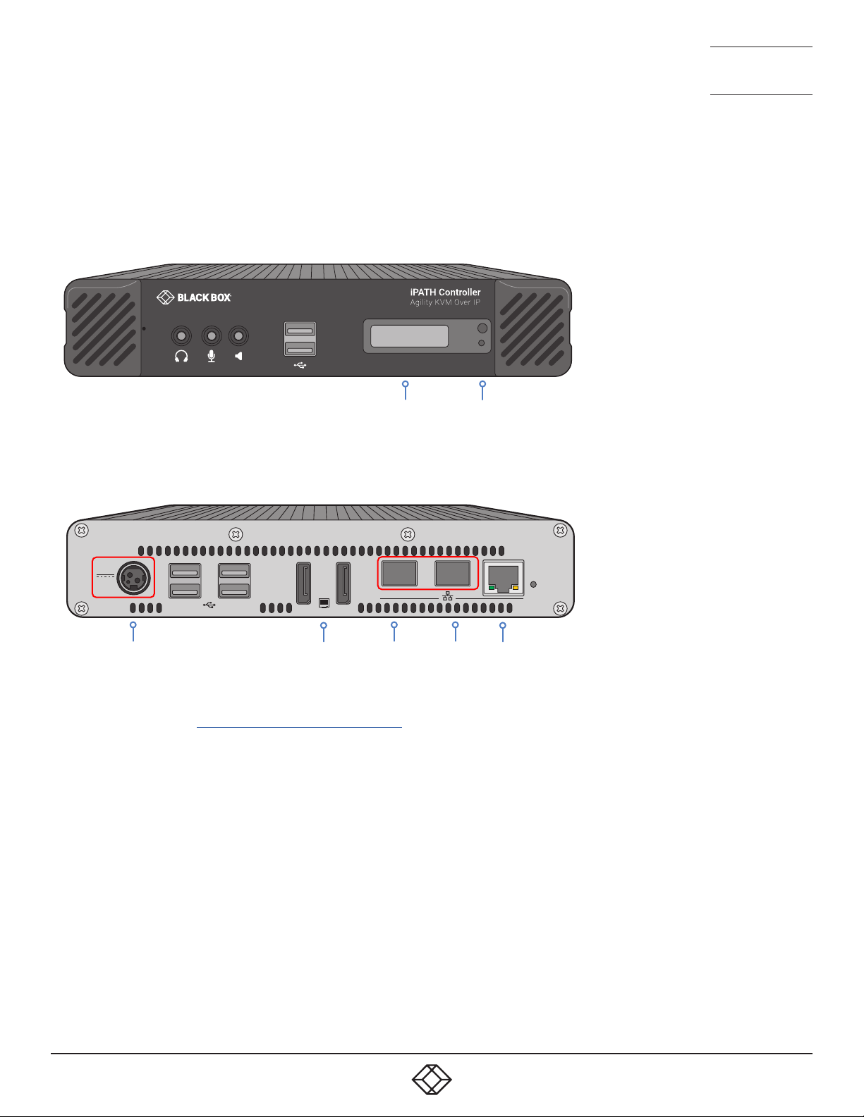
iPATH Agility Controller front panel
1
2
OLED
screen
Control
button
and status
indicator
iPATH Agility Controller rear panel - In normal use only the SFP network and power connectors are used (ringed in red)
12VDC
Power
in
35
46
1
Not
used
2
Secondary
SFP port
21
Primary
SFP port
3
Not
used
Please see the section Basic steps for a new configuration for assistance with creating iPATH installations.
8
1. 8 7 7. 87 7. 226 9 BLACKBOX.COM
Page 9
NEED HELP?
LEAVE T HE TEC H TO US
LIVE 24/7
TECHNICAL
SUPPORT
1.877.877.2269
LOCAL FEED THROUGH
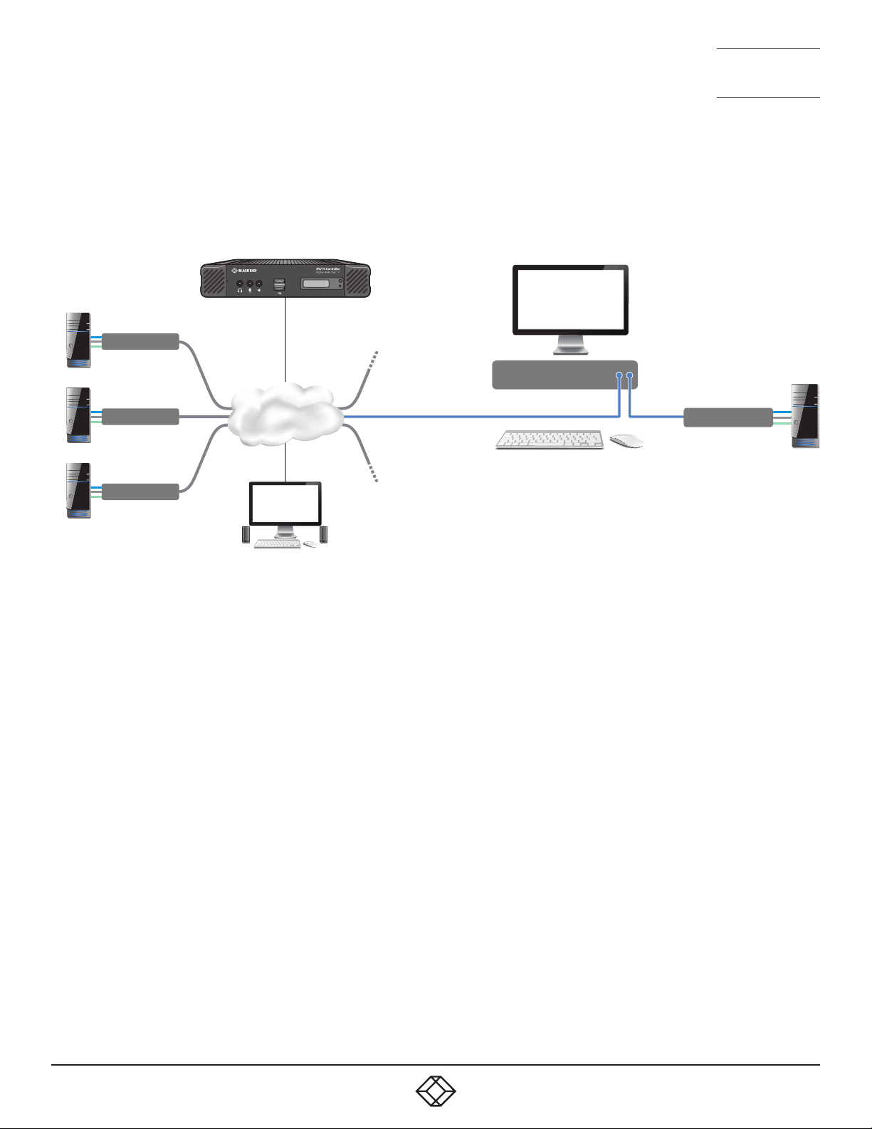
Agility remotes which are equipped with dual IP network ports can be configured to support a local link to a host PC in addition
to the main link to the network. The locally linked PC remains completely isolated from the main network.
To configure this arrangement, ensure that the IP port that is used for the local link is not allocated an IP address.
1
2
Agility Local
Agility Remote
Agility Local
Agility Local
Gigabit
Ethernet
ADMIN
Link local
Agility Local
In operation, the user of the console at the Agility
remote can use the following hotkey combination
to toggle between the network and local links:
To change from a network link to the local link:
enter CTRL+ALT+L
To change from the local link to a network link:
enter CTRL+ALT +C
to display the OSD and choose
the required connection.
Note: The L and C default hotkeys can be changed
within the iPATH control panel.
1. 8 7 7. 87 7. 226 9 BLACKBOX.COM
9
Page 10
NEED HELP?
Receiver Channel
LEAVE T HE TEC H TO US
LIVE 24/7
TECHNICAL
SUPPORT
1.877.877.2269
IPATH BASICS
Channels
Think of a channel as a ‘virtual local unit’. It is virtual because the video, audio and USB streams of a channel do not necessarily
have to originate from the same physical local unit, although in most cases they will. For instance, you could arrange for video
and USB streams to be received from one host computer, while the audio stream came from an alternative source. Alternatively,
two channels could be configured for the same host computer, each with different access rights to suit particular situations.
Groups
In order to accommodate potentially large numbers of users and devices, iPATH uses a system of groups: User Groups, Remote
Groups and Channel Groups. Groups allow the administrator to apply collective settings to all members and also to take full
advantage of Inheritance. Inheritance allows members of a group to benefit from settings and permissions made within other
groups to which their group is linked. This saves administration time because members do not need to be individually altered. For
instance, if Sam is in User Group 1, all Channels accessible to User Group 1 will be available to Sam.
User types
This guide refers to the two main categories of users involved with the iPATH system:
• An Admin (administrator) user accesses the iPATH system via a network-linked computer running an Internet browser. Once
the necessary username and password have been entered, Admin users can make changes to the operation of the iPATH
system.
• A Regular user has a keyboard, video monitor and mouse (plus speakers where appropriate) attached to an Agility remote unit
and can access one or more computers that are linked to Agility local units. The Agility remote provides an On-Screen Display
(OSD) that lists all accessible computers and allows easy access to them.
Security
Security considerations form a major part of iPATH operation, ensuring that users have rapid access only to the systems for
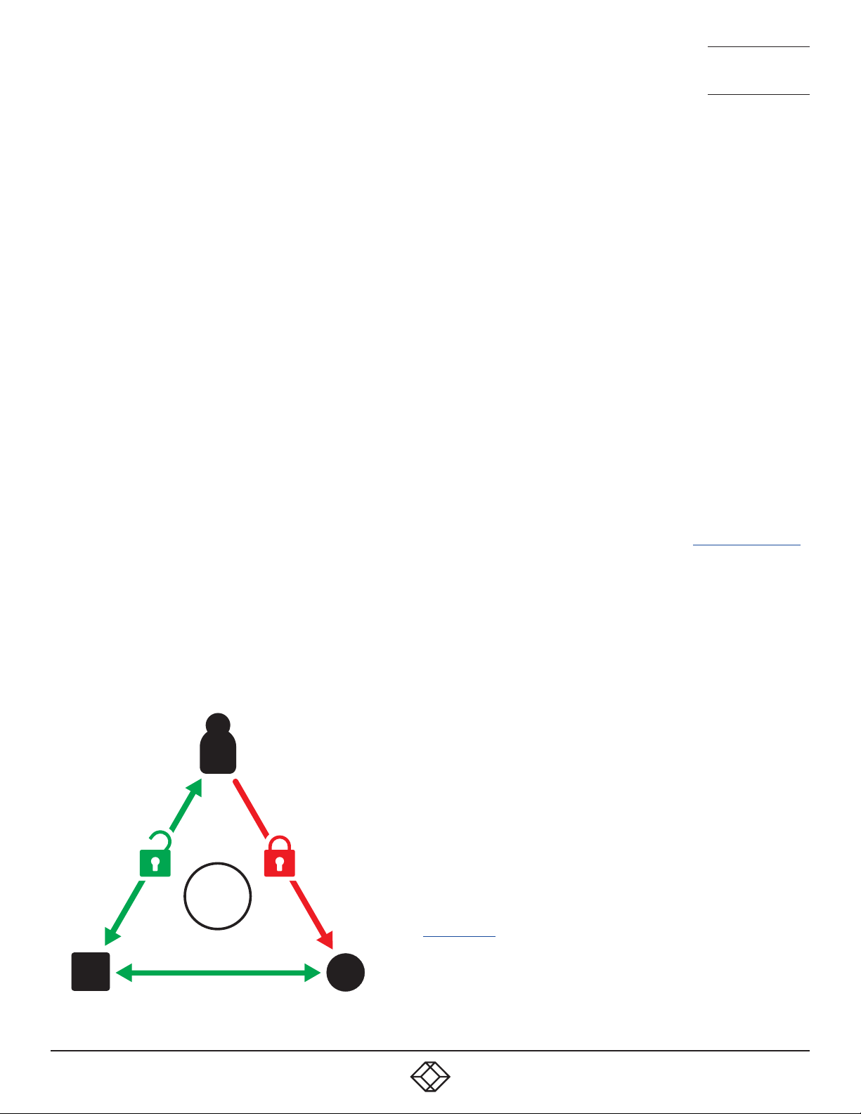
which they have permission. At its core, iPATH manages an important three-way relationship between the users, the Agility
remote(s) and the channels from the host computers.
The diagram shows a representation of the three-way relationship which exists between users, remotes and channels.
To successfully gain access to a channel:
• The user requires permission to use the remote,
• The remote requires permission to connect with the channel,
AND
• The user must have permission to access the channel.
In most cases, the need for three access permissions per connection is
unnecessary and raises administration overheads. Hence, by default,
iPATH grants open access for the user to the remote and the remote to
the channel while restricting the final, most crucial piece of the puzzle.
For those who require it, the lock upon the user to remote stage can be
applied individually or globally.
See Permissions on the next page for more details.
Access
permitted
by default
User
Access
denied by
default
iPATH
Access always permitted
10
1. 8 7 7. 87 7. 226 9 BLACKBOX.COM
Page 11

NEED HELP?
LEAVE T HE TEC H TO US
LIVE 24/7
TECHNICAL
SUPPORT
1.877.877.2269
Active Directory
To streamline administration even further, iPATH supports Active Directory. By synchronizing with an LDAP/Active Directory
server, details of users (including their usernames and group memberships) can be securely synchronised from existing
databases in order to both minimize the initial configuration as well as streamline ongoing updates.
iPATH interface
iPATH appears in two main ways depending on whether you are an administrator or a regular user.
• For administrators, full access to the iPATH Agility Controller Suite is granted. This comprehensive application shows nine
main tabbed areas: Dashboard, Channels, Remotes, Local units, C-USB LAN, Servers, Users, Presets and Statistics, each of
which contains numerous related pages of settings and options. The Dashboard provides a central location from which the
administrator can view overall operation, make various changes, database backups and also upgrade the firmware of any
linked Agility unit.
• For regular users, an efficient page layout provides a list of all channels for which you have permission to visit. Against each
selectable channel name and description, a series of icons provide clear feedback about current availability.
Permissions
Permissions exist between Users, Remotes, and Channels.
By default, all users are granted permission to access ALL remotes.
By default, all remotes have permission to connect to ALL channels.
As shown in the introductory diagram, the missing part is the permission for a user to access each channel.
Permissions between a user and a remote can be applied in any of the following ways:
• User à Remote
• User à User Group à Remote
• User à User Group à Remote Group à Remote
• User à Remote Group à Remote
Thus, a very indirect way of granting permissions could be:
• User1 is in UserGroup1,
• UserGroup1 has access to RemoteGroup1,
• RemoteGroup1 contains Channel1,
• Therefore, User1 has access to Channel1 indirectly.
1. 8 7 7. 87 7. 226 9 BLACKBOX.COM
11
Page 12
NEED HELP?
2
1
3
1
2
2
3
1
2
LEAVE T HE TEC H TO US
LIVE 24/7
CHAPTER 3: INSTALLATION
TECHNICAL
SUPPORT
1.877.877.2269
CONNECTIONS
The iPATH Agility Controller unit is supplied fully pre-loaded and permits no local user interaction. All configuration takes place
remotely via the network connections and as a result only two connections are required: Network and power.
Note: If an existing iPATH Agility Controller must be replaced, follow the important advice given within Appendix C (Swapping out
an iPATH Agility Controller).
Note: There is no need to connect a keyboard or mouse to the iPATH Agility Controller as configuration takes place across the
network connection.
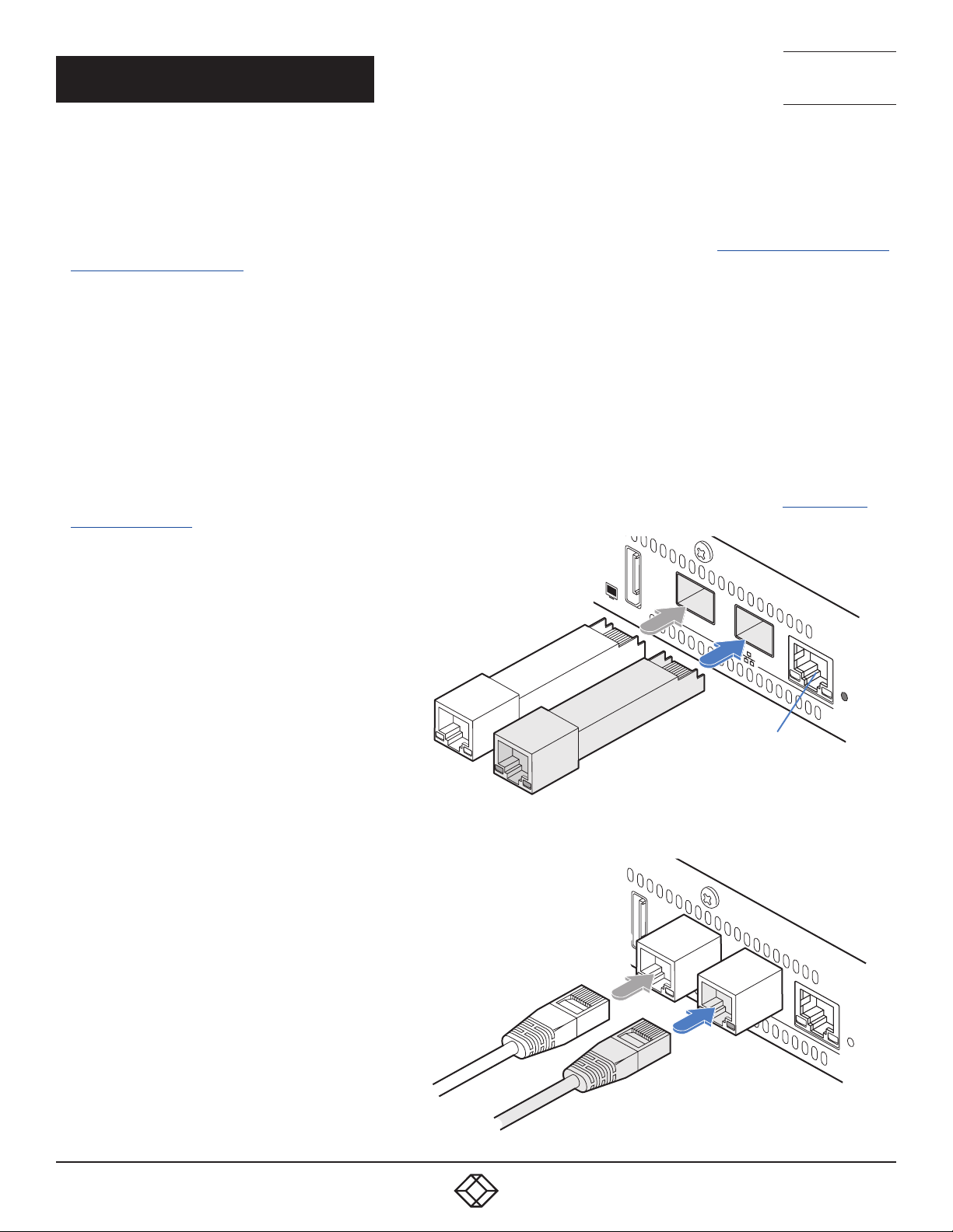
Network connections
Two SFP ports are located on the rear panel to allow CATx (or fiber) links to separate networks, according to the type of modules
that are inserted. The iPATH Agility Controller uses the two ports as follows:
• Port 1 for connection to the internal Agility network only.
• Port 2 for duplicate connection to the internal Agility network or connection to external networks to allow admin users to login
when away from the internal network.
Note: Port 1 does not support DHCP and needs to be manually configured, whereas port 2 does support DHCP. The precise
operation of the two ports are determined within the iPATH Agility Controller Management Suite, particularly the Dashboard >
Settings > Network page.
To connect the network port(s)
1 Insert the supplied SFP module into socket 1 located
on the rear panel of the unit:
Note: SFP modules that
support fiber connections are
available as options.
Optional secondary
CATx SFP module
Supplied CATx SFP module
2 Run a CAT5e or 6 link cable from the SFP module in port 1 to the
appropriate iPATH network hub or router:
3 If a second SFP module was
inserted into port 2, run an
appropriate link from that to
the required hub, router or
gateway.
Optional link for
duplicate connection or to external
network
Link to internal
iPATH network
Not used
12
1. 8 7 7. 87 7. 226 9 BLACKBOX.COM
Page 13
12VDC
12VDC
Power supply connection
IMPORTANT: Please read and adhere to the electrical safety information
given within the Safety information provided with the iPATH Agility
Controller. In particular, do not use an unearthed power socket or
extension cable.
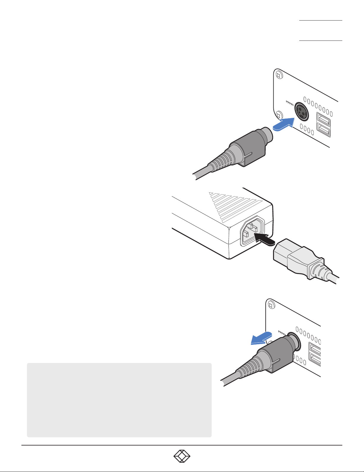
To connect the power adapter
1 Attach the output plug of the supplied power adapter to the power input
socket on the left side of the rear panel. As you insert the plug, pull
back slightly on the outer body to assist the locking mechanism until
the plug is fully inserted.
From the
power adapter
NEED HELP?
LEAVE T HE TEC H TO US
LIVE 24/7
TECHNICAL
SUPPORT
1.877.877.2269
2 Insert the IEC connector of the supplied country-
specific power cord to the socket of the power
adapter.
3 Connect the power cord to a nearby mains supply
socket.
To disconnect the power adapter
1 Isolate the power adapter from the mains supply.
2 Grasp the outer body of the power adapter plug where it connects with the
node.
3 Gently pull the body of the outer plug away from the node. As the body of the
plug slides back, it will release from the socket and you can fully withdraw
the whole plug.
IMPORTANT: Please read and adhere to the electrical safety information
given within the Safety information booklet provided with this product. In
particular, do not use an unearthed power socket or extension cable.
Note: The unit and the power adapter generate heat when in operation
and will become warm to the touch. Do not enclose them or place them in
locations where air cannot circulate to cool the equipment. Do not operate
the equipment in ambient temperatures exceeding 40 degrees Centigrade.
Do not place the products in contact with equipment whose surface
temperature exceeds 40 degrees Centigrade.
Gently pull back the plug outer
body to release the lock
1. 8 7 7. 87 7. 226 9 BLACKBOX.COM
13
Page 14

NEED HELP?
LEAVE T HE TEC H TO US
LIVE 24/7
TECHNICAL
SUPPORT
1.877.877.2269
MODEL SPECIFIC REQUIREMENTS
• Agility Zero U local units require firmware version v4.07 (or greater)
• Agility endpoints require firmware version v4.9 (or greater)
• Agility Dual endpoints require firmware version v4.9 (or greater)
TIPS FOR A SUCCESSFUL IMPLEMENTATION
Installations based upon the Black Box Agility modules vary widely in their scope and complexity. Each implementation is
distinct, however, there are numerous tips and best practice recommendations available on the Black Box website. Many tips are
concerned with the correct selection and configuration of network switches plus the choice of network topology.
General requirements
• Portfast needs to be enabled on the network switch to ensure that the Agility to iPATH communication happens in a timely
manner. Note that Cisco uses the term ‘edge port’ rather than ‘port fast’. The option is enabled on each port to which an
iPATH unit is connected. Where portfast is not enabled, if a second iPATH is added for redundancy, this could result in a misconfigured Backup server.
• If an existing iPATH Agility Controller must be replaced, follow the important advice given within Appendix C (Swapping out an
iPATH Agility Controller).
• When configuring the installation for multicasting (and to improve overall performance), the network switch(es) being used
must support a minimum of IGMP v2 snooping. For faster performance use switches that support IGMP v3.
• In order to display video resolutions that use a horizontal video resolution of 2048 pixels, the network switch must have
support for Jumbo packets.
• Please also see Appendix A - Tips for success when networking Agility units.
14
1. 8 7 7. 87 7. 226 9 BLACKBOX.COM
Page 15
NEED HELP?
LEAVE T HE TEC H TO US
LIVE 24/7
TECHNICAL
SUPPORT
1.877.877.2269
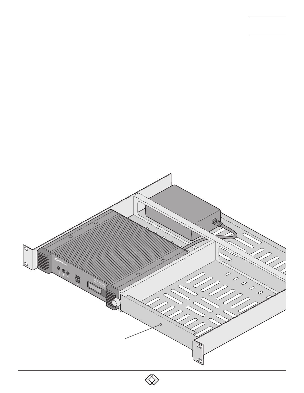
MOUNTING THE IPATH AGILITY CONTROLLER
The iPATH unit is designed to be easy to mount within a standard 19” rack using an optional rack-mount shelf. The unit is also
suitable for free standing use on the desktop. The server chassis requires just a 1U space within the rack.
To mount the iPATH Agility Controller within a rack mount
1 Install the empty rack-mount shelf into your 19” rack frame and fully secure it.
2 Place the iPATH unit into one side of the rack-mount shelf so that its rear panel butts up against the small peg located on the
side wall.
3 Place the optional blanking plate onto the other side.
4 Locate the supplied thumbscrew and spacer.
5 Insert the thumbscrew through the spacer; then insert into the small hole at the end of the center divider.
6 Gently tighten the thumbscrew so that the spacer engages with the inner edge of the iPATH unit and the blanking plate and
holds them in place.
7 Place the power adapter in the rear section of the rack-mount shelf and connect it to the iPATH unit.
8 Make all other necessary connections to the iPATH unit.
IMPORTANT: When mounting the Agility
units (and their power adapters), ensure
that the vents are not obscured and that
there is sufficient airflow. The operating
temperature range is 0 to 40ºC (0 to
104ºF) and must not be exceeded. Each
power adapter is rated at a maximum
of 68.24BTU/hr.
1
2
An optional blanking plate is available
to seal the airflow if only one device is
installed within the rack-mount shelf.
1. 8 7 7. 87 7. 226 9 BLACKBOX.COM
15
Page 16
NEED HELP?
LEAVE T HE TEC H TO US
LIVE 24/7
CHAPTER 4: CONFIGURATION
This section covers configuration of the iPATH Agility Controller Suite for administrators. For details about the regular user interface,
please see the Operation section.
TECHNICAL
SUPPORT
1.877.877.2269
SUPPORTED BROWSERS
The iPATH admin interface requires an A-grade browser with Javascript enabled.
For best results always use the latest version of any browser used.
• Google Chrome
• Firefox
• Edge*
• Safari for Mac OS*
* The most intensive testing has been carried out using Chrome and Firefox. MS Edge and Safari are known to work but testing
with these browsers has been limited by comparison.
LOGIN FOR ADMIN USERS
1 Ensure that the iPATH Agility Controller is powered on (allow 3 minutes before accessing).
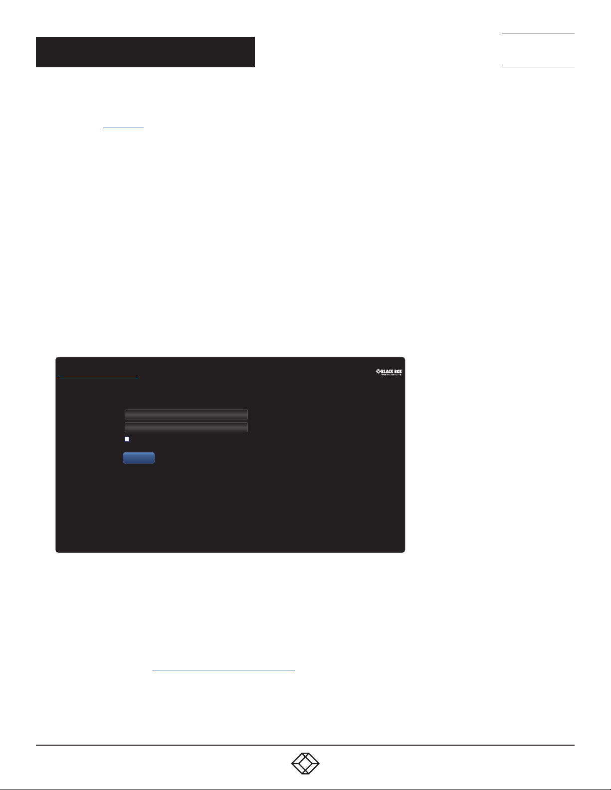
2 Using a computer located anywhere within the local network open a web browser (see Supported browsers list above) and
enter the default IP address for the iPATH Agility Controller: 169.254.1.3
The Login page will be displayed:
ServSwitchiPATH
BLACK
BOXIPACCESS
Login
™
*
Username
*
Password
Remember Me
MANAGER
Login
3 Enter your Username and Password and click the Login button.
The default username is admin and the default password is password.
You are strongly recommended to change the default admin password as one of your first actions: Go to Dashboard>Users.
Click on the furthest right icon in the admin row (configure users) and change the password for the admin user.
If you check the Remember Me box, a cookie will be stored on the computer, allowing you to access the admin section without
having to log in each time. The cookie will survive for up to the iPATH Admin Timeout period. If you do not check the Remember
Me box, you will remain logged in only for the duration of your browser session.
4 Continue to the section Important first configuration steps on the next page.
Forgotten password
If necessary, click the Forgotten password link to display an assistance page where a secret code will be given. Provide the secret
code to Black Box support or your distributor to obtain an unlock code which can then be entered to reset your password and
gain access.
16
1. 8 7 7. 87 7. 226 9 BLACKBOX.COM
Page 17

NEED HELP?
LEAVE T HE TEC H TO US
LIVE 24/7
TECHNICAL
SUPPORT
1.877.877.2269
IMPORTANT FIRST CONFIGURATION STEPS
There are several important configuration steps that must be carried out when starting a new iPATH Agility Controller for the first time.
To determine the iPATH Agility Controller’s rôle and main IP address
1 Switch on and log in to the iPATH Agility Controller; you will be presented with the Servers page.
2 Within the Server page, choose the Rôle of this new iPATH Agility Controller:
• Solo - This will be the only iPATH Agility Controller on the network (with no redundancy and failover), or
• Primary - This server will be used as part of a redundant cluster of iPATH servers, where it will be the main server used to
manage the Agility units.
3 Click the Save button. You will next be presented with the Dashboard > Settings > Network page.
4 See the warning below - do not carry out this step while the system is in operation. Within the Ethernet Port 1 section at the
top of the page, change the default iPATH IP Address (and Netmask) options to settings that suit your network configuration
and which will be used henceforth for this server.
IMPORTANT: The Ethernet Port 1 iPATH IP Address and Netmask settings must NOT be changed during operation of the
system. Changing these will invalidate the system’s security and require intervention from the Black Box technical support
staff to restore to a working state.
5 You can now either:
• Continue with other settings on the same page (See To choose how IP addresses are applied to Agility units right), or
• Click the Save button. After a short delay the web browser will automatically redirect itself to the new IP address so that you
can continue administering the iPATH Agility Controller.
Note: Ensure that your computer can view the new IP address, otherwise the iPATH Agility Controller will appear to be offline.
Depending on your network configuration and that of the computer, you may need to change the computer’s configuration to be
able to see iPATH Agility Controller’s new network address.
IMPORTANT: To use subnet operation, you must have a DHCP server within your network in order to assign IP addresses to the
iPATH and Agility endpoints. If subnet operation is used without a DHCP server, the Agility endpoints will not communicate with
iPATH As a result, the iPATH will need a factory reset in order to be able to revert it back to single subnet mode.
To choose how IP addresses are applied to Agility devices
1 Login again to the iPATH Agility Controller and choose the Dashboard > Settings > Network page.
2 The Subnet Operation option may, or may not, be presented at the top of the page.
Note: If Subnet Operation is not present, the iPATH Agility Controller will operate as per the Off setting described below.
When the Subnet Operation option is present, you have the following choices:
• Off - iPATH can administer a single subnet and will use its own DHCP (Dynamic Host Configuration Protocol) server to
automatically assign IP addresses to new Agility devices, drawing upon a pool of spare addresses defined by you.
• On - iPATH can administer devices across multiple subnets, but will rely upon an external DHCP server to assign valid IP
addresses to new Agility devices.
3 If you chose the Off setting, you now need to define the boundaries of the IP address pool that will be used by the internal
DHCP server. Enter valid start and end addresses to the IP Pool Lower Limit and IP Pool Upper Limit options.
Note: If you chose the On setting, you will need to perform a similar operation within the external DHCP server. For details about
DHCP server requirements, see Appendix H.
For further details about other options within this page, see Dashboard > Settings > Network.
4 When all options have been set, click the Save button.
5 If you need to change the operation of iPATH from single subnet to multi-subnet (or back again) this option only appears after
a successful factory reset of iPATH
IMPORTANT
Note: If an existing iPATH Agility Controller must be replaced, follow the important advice given within Appendix C (Swapping out
an iPATH Agility Controller).
1. 8 7 7. 87 7. 226 9 BLACKBOX.COM
17
Page 18

NEED HELP?
LEAVE T HE TEC H TO US
LIVE 24/7
TECHNICAL
SUPPORT
1.877.877.2269
ADDING AGILITY UNITS
When new Agility local and remote units are added to a network, they are designed to automatically announce themselves* to the
iPATH Agility Controller. Once the iPATH Agility Controller receives their announcement(s), the Agility units will be added to the
administrator’s view of the Dashboard. From here you can then begin to configure each new Agility unit.
* Agility units can be configured either from their own browser-based configuration utility or via the iPATH Agility Controller. Once
an Agility unit has been configured in one way, it cannot be reconfigured using the other method without undergoing a factory
reset. This policy is in place to help prevent accidental overwriting of configurations. It also means that once an Agility unit has
been locally configured, it will not announce itself to the iPATH Agility Controller upon being added to a network.
When new Agility devices announce themselves, depending upon how it was initially configured (see Important first configuration
steps), the iPATH Agility Controller will either assign IP addresses to new Agility units automatically, or will rely upon an external
DHCP server to do the same. Either way, providing each Agility device is not already configured and announces itself to the
iPATH Agility Controller (see right for potential issues that can prevent this), they will be automatically provided with a suitable IP
address so that they may operate within the network. Once Agility units have been added, you can use the iPATH Agility Controller
Dashboard to select and further configure any or all of them.
If an Agility unit is not located
There are several reasons why an Agility unit might not be located by iPATH:
• The Agility unit has been locally configured or is otherwise not using its factory default setting. Try performing a factory reset
on an Agility that is not being located (see next page).
• The Agility unit is not located in the same Ethernet segment as the iPATH Agility Controller. Double check connections and
move units where necessary, so that all reside within the same Ethernet segment.
• There is a potential cabling problem between the Agility and iPATH units. Check and where necessary, replace faulty cables.
18
1. 8 7 7. 87 7. 226 9 BLACKBOX.COM
Page 19
NEED HELP?
WWW.BLACKBOX.COM
WWW.BLACKBOX.COM
LEAVE T HE TEC H TO US
LIVE 24/7
TECHNICAL
SUPPORT
1.877.877.2269
Agility manual factory reset
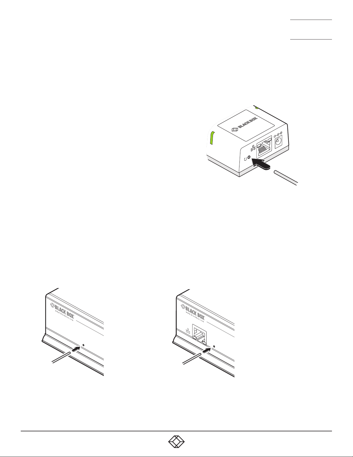
Where a previously configured Agility unit is being added to a network for control by an iPATH Agility Controller, you need to
ensure that the unit is reset to its default configuration. The procedures given here cover how to perform a reset on the various
types of Agility units.
Agility Zero U models
1 Power on the Agility Zero U unit.
2 Use a narrow implement (e.g. a straightened-out paper clip) to
press-and-hold the recessed reset button on the front panel
for roughly fifteen seconds, until the indicators turn blue (Note:
alternating red/green indications will occur during the fifteen
second period while the button is still pressed).
3 Release the reset switch.
The indicators will remain blue for a short while (less than ten
seconds) while the unit configures itself and should then change
to green if all connections are correct; or orange if one or more of
the video, USB and/or network links are missing.
Use a straightened-out paper
clip to press the reset button
for roughly 5 seconds
Agility and Agility Dual models
1 Remove power from the Agility unit.
2 Use a narrow implement (e.g. a straightened-out paper clip) to press-and-hold the recessed reset button on the front panel.
With the reset button still pressed, re-apply power to the unit and then release the reset button.
After roughly eight seconds, when the factory reset has completed, five of the front panel indicators will flash for a period of
three seconds to indicate a successful reset operation.
Use a straightened-out
paper clip to press the
reset button while power-
ing on the unit
Agility
Agility Dual
1. 8 7 7. 87 7. 226 9 BLACKBOX.COM
19
Page 20
NEED HELP?
LEAVE T HE TEC H TO US
LIVE 24/7
TECHNICAL
SUPPORT
1.877.877.2269
FRONT PANEL INDICATIONS
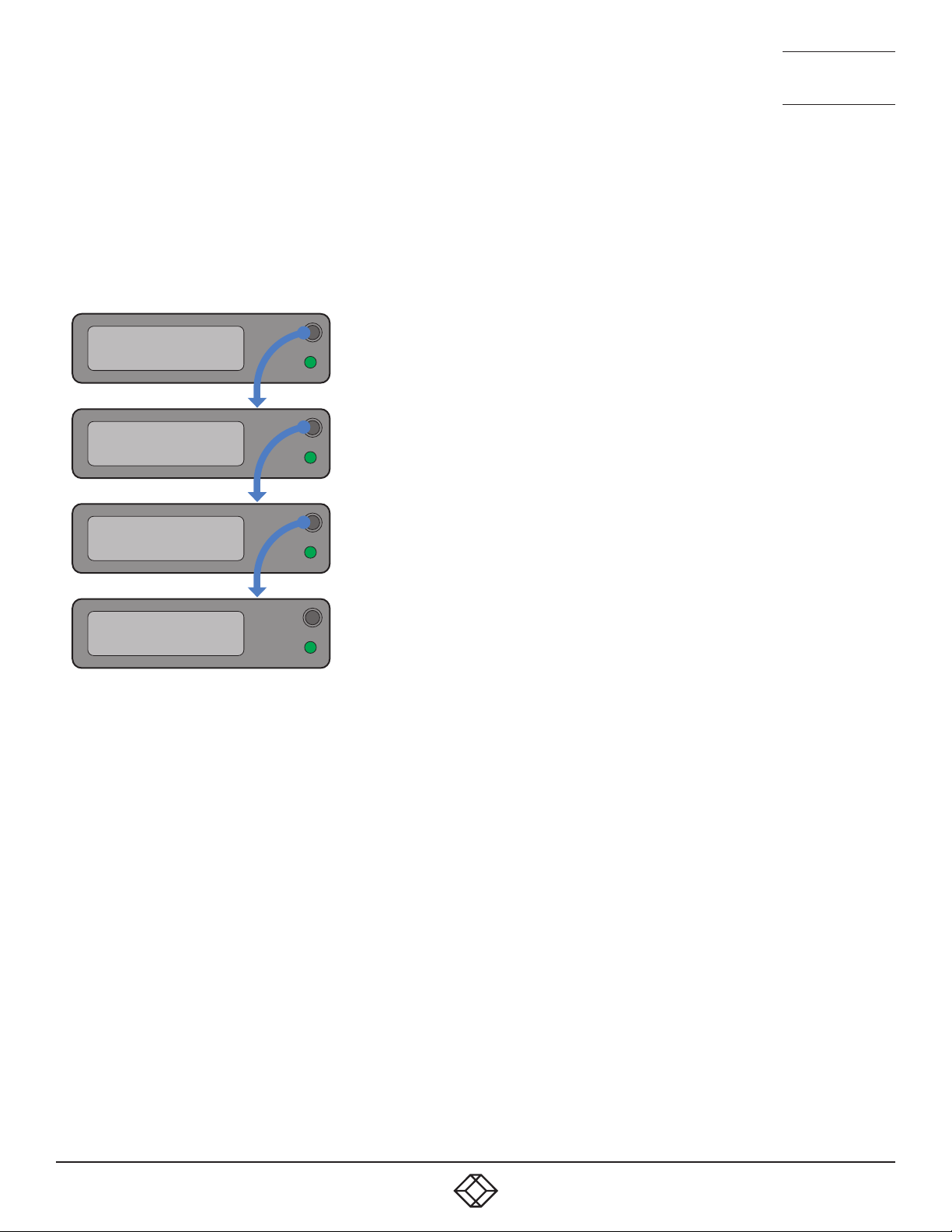
The front panel of the iPATH Agility Controller unit features an OLED information screen plus a single indicator capable of
producing numerous color and flash patterns to provide a useful guide to operation.
OLED screen
Press and release the button to wake the OLED screen and begin showing information. Press the button repeatedly to change
between subjects:
iPATH server
Online
Server name
Server status
primary
Port 1 address
10.0.0.1
Network port 1
Port 2 address
-
Network port 2
Indicator color and flash patterns
The single front panel indicator uses varying color and flashing patterns to signal key status:
Off No power.
Green Powered on and network connection established.
Yellow Boot process complete or (during operation) network connection lost.
Blue Factory reset mode active.
Green/blue flash Upgrade mode active.
20
1. 8 7 7. 87 7. 226 9 BLACKBOX.COM
Page 21

NEED HELP?
LEAVE T HE TEC H TO US
LIVE 24/7
TECHNICAL
SUPPORT
1.877.877.2269
THE DASHBOARD TAB
The Dashboard is your main point of contact for checking and changing the general status of all iPATH operations.
Click the DASHBOARD tab to view its initial home page.
The various other Dashboard pages (e.g. Settings, Backups, Updates, etc.) are selectable within the blue section located just
below the tabs.
Dashboard > Home
• Shutdown button - Allows the admin user to shut down the iPATH Agility Controller. The OSD will no longer work on Remotes.
The iPATH Agility Controller will need to be manually started again when next required.
• Restart - The admin user can reboot the iPATH Agility Controller. The OSD and admin section will be unavailable while the
server is rebooting. The time for a reboot can vary significantly depending upon settings such as ETH1 obtaining an IP adress
by DHCP, or whether or not the clock is maintained by NTP.
Within the Home page*, the different sections provide a variety of information:
• Warning messages - Live alerts are displayed concerning any devices that are offline, rebooting, recently added or
unconfigured.
• Latest Active Connections - shows the five most recent active sessions, detailing for each: When the session started; which
user/remote/channel is involved; the connection type (icons show audio, video, serial, USB, exclusive) and IP addresses in use.
The red unplug icon on the far right allows the admin user to disconnect a connection.
• Event Log - shows all actions performed by the admin or end-users within the iPATH system. See also the Event Log page.
• Latest Channels Created - shows the last five channels created within the iPATH system. A channel is created by default when
a new local unit is added and configured. The edit icon next to a channel allows the admin user to configure the channel.
• Latest OSD Logins - shows the last five users who logged in (either to the iPATH admin or at an Agility Remote).
• Latest User Registrations - shows the last five users added to the iPATH system, with a link to edit the user’s details/
permissions.
• Latest Channel Changes - shows the last five users who changed a channel, either while using the on-screen display (OSD) at
an Agility Remote, or via the iPATH admin control panel.
• Latest Remotes Added - shows the last five remotes to be added and configured within the iPATH network. Click to
configure a remote; click to connect to a channel; or click to disconnect an existing connection.
• Latest Locals Added - shows the last five locals to be added and configured within the iPATH network. Click to configure a
local.
* The Home page is auto-refreshed every thirty seconds to ensure that the latest information is always available.
1. 8 7 7. 87 7. 226 9 BLACKBOX.COM
21
Page 22

NEED HELP?
LEAVE T HE TEC H TO US
LIVE 24/7
TECHNICAL
SUPPORT
1.877.877.2269
Dashboard > Settings
Click the Settings option below the Dashboard tab.
The Settings section contains global configuration options for the iPATH system and is divided into eight pages, each accessible
by clicking the relevant button located below the blue options bar:
For configuration options that affect individual remotes, users channels, etc., see the sections dealing with those tabs.
Dashboard > Settings > General
Remote OSD Timeout
Determines the time period of inactivity within the OSD after which a standard user will be automatically logged out.
iPATH Administrator Timeout
Determines the time period of inactivity within the iPATH config pages after which an admin user will be automatically logged out.
Anonymous User
Determines which user is shown in the log when a remote is set to ‘No login required’.
Disable Password Reset
This prevents the password reset button from appearing on the login page.
Hide Dormant Devices / Show Outdated Devices
These options: a) hide devices that have been offline for more than 24 hours and b) show devices that are outdated for the current
iPATH version (both exclude RDP servers).
Grant All Users Private Access
Determines whether a user can connect to a channel privately and thus prevent any other users from simultaneously connecting to that
channel. If not set, users can only connect in Video-Only mode or Shared mode. Settings that are applied specifically to a user will override
settings applied to user groups they’re in, which in turn override this global setting.
Note: If a user has Private Access mode granted or NOT granted at user level, then it doesn’t matter what settings there are above
(usergroups or global).
• If a user is set to inherit “Allow Private?” mode from their user groups, if any one of their user groups has “Allow Private?” mode
granted, then the user will have it granted, even if the rest of the user’s usergroups have private mode not granted.
• If a user is set to inherit “Allow Private?” mode from their user groups, and one of the user groups is set to inherit from the global
setting - if that global setting is “Allow Private?” mode, then effectively the user group is “Allow Private?” mode so the user will be
allowed private mode.
Grant All Users Remote OSD Access
If enabled, allows remotes to be switched remotely from another remote’s OSD menu.
Grant All Users Force Disconnect
If enabled, permits any user logged in at a remote to disconnect a channel or preset established on that remote by another user.
Show Disconnect All
If enabled, this provides the option to users to collectively disconnect all remotes.
22
1. 8 7 7. 87 7. 226 9 BLACKBOX.COM
Page 23

NEED HELP?
LEAVE T HE TEC H TO US
LIVE 24/7
TECHNICAL
SUPPORT
1.877.877.2269
Allowed Connection Modes
Determines the global setting that will be applied to all new channels concerning connection modes. The setting made here is only
applied as a default and can be overridden at the channel level, where necessary. Options are:
• Video-Only: Allows users only to view the video output, the USB channel is denied.
• Shared:* Allows users to control a system in conjunction with other users.
• Exclusive: Grants exclusive control to one user while all others can simultaneously view and hear, but not control, the output.
• Private: Allows a user to gain private access to a system, while locking out all others.
Note: By default, all new channels are set to inherit this global value. So it’s easy to change all channel connection modes simply
by changing the global setting. If a channel has its own setting, the global setting has no effect on that channel.
* If USB is disabled, Shared mode will not be available as an option.
Rows per Page
The number of rows to display in all paginated tables in the admin section.
Locale
Determines the language shown on the OSD menus of the remotes. Note the admin configuration web pages remain in English.
Debug Level
This allows information to be collected for diagnostic purposes. DO NOT change this setting from normal unless advised by Black
Box Support.
API - Login Required
If enabled, the anonymous use of the iPATH API will be disallowed.
API - Anonymous user
Determines the user permissions to be used when the API is accessed without logging in.
Licence - Supported Devices - Indicates the limits of the current license.
Upgrade License - (see Appendix D for details)
Displays information about the number of devices that can be connected to the iPATH Agility Controller.
Licensed Features - Displays the level of operation permitted under the current license. Click view/change to see more detail and
gain a unique identier that can be declared to Black Box when upgrading a license.
1. 8 7 7. 87 7. 226 9 BLACKBOX.COM
23
Page 24

NEED HELP?
LEAVE T HE TEC H TO US
LIVE 24/7
TECHNICAL
SUPPORT
1.877.877.2269
Dashboard > Settings > Locals
This page applies a standard global configuration to all locals.
Magic Eye
Determines whether the Magic Eye feature should be enabled on Agility locals. Magic Eye works to overcome the issues with
increased bandwidth usage caused by ‘dithering’ techniques used on some computers, such as Apple Macs. See the Agility Dual
user guide for more details.
EDID
Determines how the video configuration details should be determined: Either harvested from the connected display screens (USE
CONNECTED MONITOR’S EDID) or by selecting a static fixed EDID setting from the list (e.g. GENERIC 16:9, 1920x1080 HD1080,
1600x1200 UXGA, etc.). Using a fixed EDID setting can significantly speed up video switching times as EDIDs do not need to be
checked, however, all of the installed monitors need to support the chosen resolution. Where EDIDs are checked, enabling EDID
Optimisation (below) can help to regain some of the switching speed.
Note: Care must be taken when selecting a Dual Link Video resolution (e.g. 2560x1600) as certain Agility units do not support Dual
Link Video resolutions. In the case of a Dual Link EDID being set in the Global settings, no EDID will be set on Video port 2 of dual
port Agility locals.
EDID Optimisation
When this option is ticked, the local units will compare the native resolution settings of monitors when switching. If a monitor
has the same native resolution as the previous one, the new EDID is not sent to the graphics card. This speeds up switching as
the graphics card does not need to go through a hotplug detect routine when a new remote is switched to that channel. If the new
remote has a monitor with a different native resolution, then the EDID will be updated to allow for a change in video mode.
Audio EDID
For locals which support digital audio via the DisplayPort connection(s), this setting determines how the audio should be
configured: (USE CONNECTED MONITOR’S EDID) or a static setting: NONE, 2 CHANNEL (Stereo), 6 CHANNEL (surround 5.1) or
8 CHANNEL (surround 7.1). Using a fixed EDID setting can significantly speed up switching times as EDIDs do not need to be
checked, however, all of the installed audio devices need to support the chosen format. Where EDIDs are checked, enabling Audio
EDID Optimisation (below) can help to regain some of the switching speed.
Audio EDID Optimisation
When this option is ticked, the locals will compare the digital audio settings when switching. If a remote’s digital audio settings
are the same as the previous one, the new EDID is not sent to the host system. This speeds up switching as the host system does
not need to go through a hotplug detect routine when a new remote is switched to that channel. If the new remote uses a different
audio setting, then the EDID will be updated to allow for a change in audio mode.
Hot Plug Detect Control
Determines whether to enable hot plug detection for monitors. By default this is enabled.
Hot Plug Detect Signal Period
By default this is set at 100ms, which is sufficient for most graphics cards. Occasionally it may be necessary to adjust this. A
Black Box support engineer will advise if necessary.
24
1. 8 7 7. 87 7. 226 9 BLACKBOX.COM
Page 25

NEED HELP?
LEAVE T HE TEC H TO US
LIVE 24/7
TECHNICAL
SUPPORT
1.877.877.2269
Background Refresh
The number of frames between sending an entire frame of video data. Setting this to a longer period or disabling this will reduce
the bandwidth required.
Compression Level
The newer AFZ+ codec complements the existing AFZ codec by providing greater compression for increased speed where pixel
perfect results are not the primary focus. The local video configuration page allows you to choose the required compression
mode. Choices are:
• ‘Pixel Perfect’ - only uses pixel perfect AFZ,
• ‘Adaptive’ - guarantees frame rate, builds to pixel perfect,
• ‘Smoothest Video’ - forces the maximum compression, or
• ‘Advanced’ - allows you to choose the minimum and maximum compression modes:
1 = ‘AFZ only (pixel perfect),
2 = ‘AFZ+ Minimum compression’,
3 = ‘AFZ+ Middle compression’, or
4 = ‘AFZ+ Maximum compression’.
USB Speed
Determines standard USB operation: USB1 Full speed or USB 2 Hi-speed.
USB Hub Size
Select either a 13 or 7 port USB hub. This determines the number of USB devices that can be connected to a single Local.
Note: In order to access the BIOS on some host machines it is necessary to change this setting to 7 ports.
Enable Dummy Boot Keyboard
It is often necessary to have a keyboard reported at start up. This setting means that a “Virtual Keyboard” is always reported to
the USB host. It may be necessary to disable this for use with some KVM switches.
Enable Audio
This option controls the standard analog audio feed, available via the 3.5mm audio jacks.
Enable Digital Audio
This option controls the (multi-channel) digital audio feed available via the HDMI connection as supported by certain Agility
devices - at present only supported by the Agility Zero U.
Reserved USB ports
This setting lets you set aside a specific number of USB ports (up to 8) on the local that can be made available for certain USB
devices which require a quirk setting under advanced USB features, connected to a remote.
Note: This setting can only be applied globally it is not found with individual local configurations because all remotes need to
know how many USB ports are available for the advanced USB features.
Serial port options
These allow you to match the serial configuration being used by the attached PC host.
1. 8 7 7. 87 7. 226 9 BLACKBOX.COM
25
Page 26

NEED HELP?
LEAVE T HE TEC H TO US
LIVE 24/7
TECHNICAL
SUPPORT
1.877.877.2269
Dashboard > Settings > Remotes
This page applies a standard global configuration to all remotes.
OSD Hotkeys
Determines whether the hotkeys that invoke the OSD are enabled or disabled.
Connection Hotkeys
Determines whether the hotkeys that switch channels are enabled or disabled. This affects all of the hotkey settings below.
Disconnect Hotkeys
Determines the hotkey combination used to end the current connection.
Shortcut and Extended Hotkeys
Shortcut hotkeys allow quick connection to channels 0 to 9. Extended hotkeys also allow quick connection to those same
channels, but then offer a further set of connections from channels 10 to 99. It is important to set a different combination of
Extended Hotkeys to those configured for the Shortcut Hotkeys setting.
Note: For all types of hotkeys, Left Ctrl and Left Alt are the default settings. It is not possible to use a mixture of left and right Ctrl/
Alt/Shift keys for any given function.
Other Hotkey Settings
The next six settings determine the Hotkeys that can be used to invoke certain functions, such as last-used channel selection,
connection mode and feedthrough selection.
For all of these hotkey settings it is possible to choose mouse buttons to perform the functions, however, it is not possible to use
a mixture of mouse buttons and keyboard keys in combination, it must all one or the other type.
Show Multi-User Information
When set to Yes, the names of other users who are currently viewing the same channel will be displayed within the OSD.
Login Required
Determines whether it is necessary to log into the remote.
OSD Login Message
Text entered in this box will be displayed as a message to all users who access the OSD login page.
Enable Remote OSD Alerts
Determines whether pop up OSD alerts should be displayed for users.
Show Current Channel
When enabled, displays the channel name on the OSD banner (in the position determined in the setting below).
OSD Banner Position
Determines the screen location of the OSD banner (when enabled in the above setting), which will state the currently viewed
channel name.
Touch show OSD enable
Determines whether the OSD can be shown on a touch screen device when supported by certain Agility devices.
26
1. 8 7 7. 87 7. 226 9 BLACKBOX.COM
Page 27

NEED HELP?
LEAVE T HE TEC H TO US
LIVE 24/7
TECHNICAL
SUPPORT
1.877.877.2269
USB Connector to Monitor number mapping
Allows you to share the various emulated USB ports between the connected video displays.
Video Compatibility Check
When enabled, this option reads the EDID from the attached monitor and determines whether it is capable of displaying the
selected video mode before connecting a channel. This prevents the remote showing a black screen and the user being locked
out because a dual link resolution has been selected to display on a single link monitor.
Audio Compatibility Check
Applicable only to remotes which are capable of processing multichannel digital audio via their DisplayPort connections. When
enabled, this option reads the EDID from the attached monitor/audio system and determines whether the remote’s current audio
setting (e.g. 2 Channel, 6 Channel, 8 Channel) is capable of correctly playing the selected audio (e.g. Stereo, 5.1 or 7.1) mode
before connecting a channel.
Force 60Hz
If enabled, the remote frame rate is held at 60Hz regardless of the video input frame rate. The Video Switching options (below)
cannot be altered when this option is enabled.
Video Switching
Provides two options for video switching:
• Fast Switching (default state) - Retains the same frame rate (at either 50Hz or 60Hz) depending upon which video resolution
was displayed first.
• Match Frame Rate - Follows the source frame rate and will change the frame rate every time this changes even if the video
resolution doesn’t change. If you have one remote switching between 1920x1080@60Hz and 1920x1080@50Hz then this
setting will change the frame rate from 60Hz to 50 Hz every time that you switch.
Keyboard Country Code
Select the country code of the keyboard connected to the remote.
Audio Input Type
Select the required audio input type: Mic or Mic Boost.
1. 8 7 7. 87 7. 226 9 BLACKBOX.COM
27
Page 28

NEED HELP?
LEAVE T HE TEC H TO US
LIVE 24/7
TECHNICAL
SUPPORT
1.877.877.2269
USB Settings
HID Only
This option allows you restrict USB devices to allow only HID (mice, keyboards, tablets, touchscreens, etc.) devices to be
connected to the remote(s).
Block Mass Storage
This option allows you to prevent the use of USB mass storage devices at the remote(s).
The HID Only and Block Mass Storage options both affect how USB devices are supported at the remote(s). Their use in
combination can produce the following results:
HID Only Block Mass Storage Outcome
No No No USB restrictions
Yes No
No Yes
Yes Yes
Disable Isochronous Endpoint OSD Alerts
When an isochronous USB device is connected to the remote there will no longer be a warning message. Agility units do not
support isochronous devices.
Allow only HID devices
(Mass storage devices are also blocked)
Exclude mass storage devices but
allow other USB peripherals (e.g. mice,
keyboards, tablets, touchscreens, etc.)
Allow only HID devices
(Mass storage devices are blocked)
Enable Isochronous Endpoint Attach
Some USB devices combine many USB devices behind a USB hub. e.g a keyboard with audio support. By enabling this option,
devices will be allowed to connect to Agility remotes, however, the isochronous part (e.g. the audio component) of the devices will
not work.
Advanced Port Features
This section allows you to determine USB port behaviour for use with certain USB devices.
The default is no reserved ports, Merging enabled and no feature code (or Quirk) set. It is recommended that these are left at the
default settings and are only changed under advice from a Black Box support engineer.
For each of the four USB ports on the remote, certain rules can be applied depending upon the USB device connected.
If you have reserved USB ports on the local, you can select which USB port to use for a particular device.
You can turn off USB merging for a particular port. This will slow down switching as the USB device will be enumerated every
time that you switch.
You can also enter an advanced feature if it is necessary for your USB device. The drop down lists the feature codes for some
known USB devices. Otherwise please contact your local support engineer for advice.
28
1. 8 7 7. 87 7. 226 9 BLACKBOX.COM
Page 29

NEED HELP?
LEAVE T HE TEC H TO US
LIVE 24/7
TECHNICAL
SUPPORT
1.877.877.2269
Dashboard > Settings > Servers
This page is used to configure redundant operation for the iPATH servers.
Two or more servers can be added onto the same subnet or Vlan. One iPATH box is the Primary (or Master) the other is the
Backup (or Slave). If the Primary server fails for any particular reason then the Backup will take over until the Primary is repaired.
This functionality is only possible if the licenses of the both iPATH units match. Both iPATH units need to be able to control the
same number of endpoints.
When in Multi-subnet mode it is possible to place additional servers on a different subnet or Vlan. These servers are referred to
as satellites.
Primary Timeout
The time (in seconds) for the Primary server to be unavailable before the Backup takes over.
Quiescent Timeout
The time after which an inactive (Quiescent) server is assumed to have disappeared.
Backup Check Interval
The interval between the Primary server querying its backups to determine if they are all on-line.
Backup Timeout
The period of time that a backup server can be off line or uncontactable before it is treated as a failed server.
Require Authentication?
If set to ‘Yes’, then a new, unconfigured iPATH Agility Controller will be unable to join the cluster automatically; it’s behaviour will
be to report itself as unconfigured and quiescent, and request a password. Entering the cluster password will then allow it to join
the cluster as a Backup.
Cluster Password
This is the password that is used for iPATH-to iPATH https queries, if the Require Authentication option is enabled.
1. 8 7 7. 87 7. 226 9 BLACKBOX.COM
29
Page 30
NEED HELP?
LEAVE T HE TEC H TO US
LIVE 24/7
TECHNICAL
SUPPORT
1.877.877.2269
Dashboard > Settings > Network
This page applies global network parameters to the iPATH network.
iPATH Connectivity
Require SSL for Web
If set to yes, a certificate needs to be downloaded and all connections will then take place using HTTPS:// connections rather
than the default HTTP:// connection types.
Gateway IP Address
Defines the IP address of an optional gateway device.
Note: Only a single gateway can be specified within an iPATH Agility Controller. If both Ethernet ports are to be used in multisubnet mode, it is important to specify a single gateway IP address that suits both Ethernet ports. Communications between
iPATH and the Agility endpoints on the different subnets will be affected if using multi-subnet mode without a jointly valid
gateway.
Ethernet Port 1
The primary iPATH Agility Controller Ethernet port can only be configured using a static IP address. Use the three options provided to
configure the IP address, netmask and DNS server address.
Ethernet Port 2
The Backup iPATH Agility Controller Ethernet port can be configured to either: gain its details via a DHCP server; use a Static IP
address, netmask and DNS server address, or alternatively be set to Bonded operation, whereupon three further Bonding Mode
options are displayed:
• Active-Backup - This can be used when both of the iPATH Agility Controller’s network connections are linked to the same
network switch. This option provides a fail-over to cater for the possibility of hardware failure or connectivity failure between
the iPATH Agility Controller and the switch.
In this mode, one of the iPATH Agility Controller’s network ports will be active while the other remains dormant. If the active
port experiences a failure, such as a loss of connection, its configuration is automatically transferred to the Backup port. Once
the original primary port resumes connectivity, this will become the backup and be placed into a dormant mode.
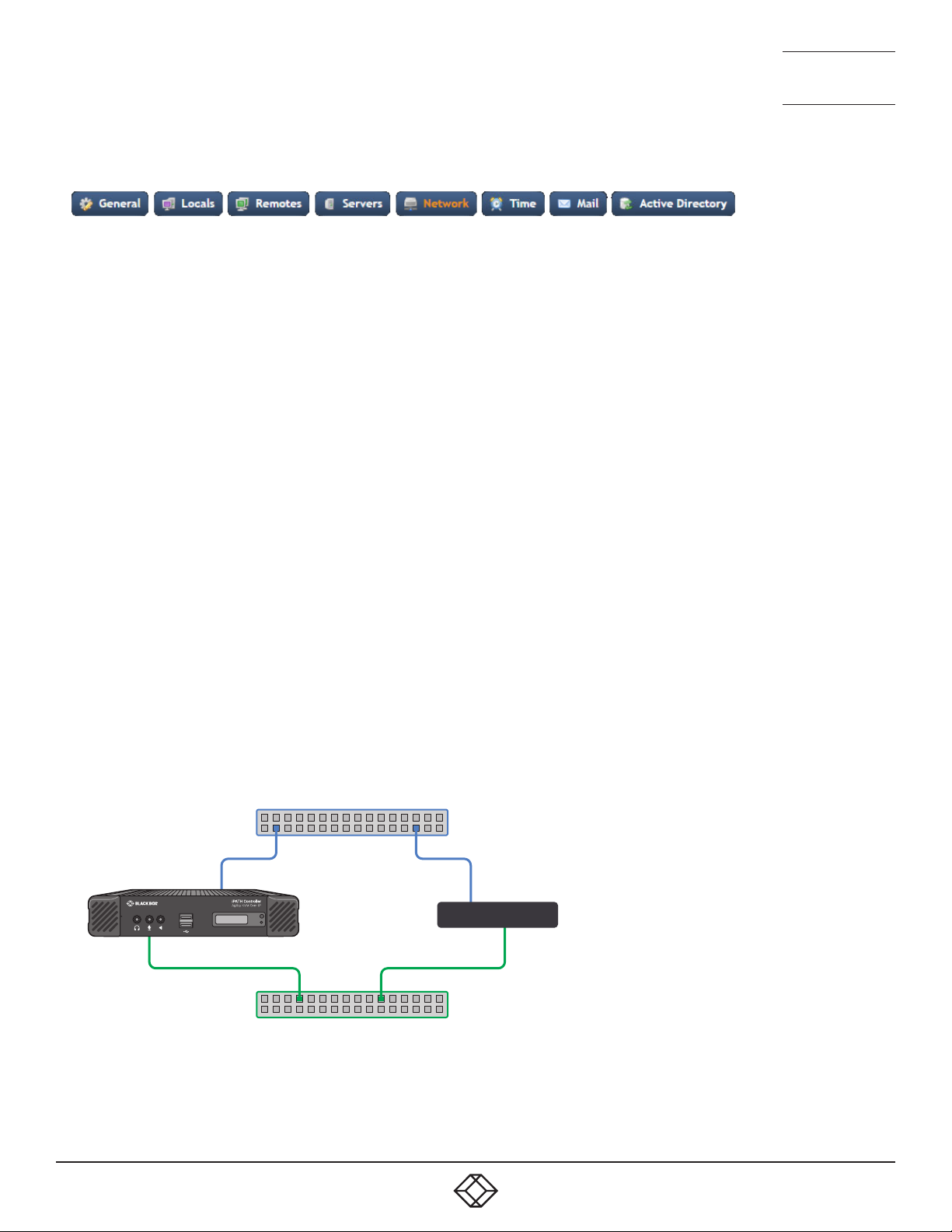
Switch 1
Port 1
Port 2
1
2
Switch 2
Agility
• Broadcast - This option would be used when the twin ports of the iPATH Agility Controller and all attached Agility devices are
split between duplicate networks:
The ‘Separate Device Networks’ option mentioned earlier would be enabled on the iPATH Agility Controller and the respective
network connections on the endpoints are connected accordingly (e.g. copper to copper on only switch 1 and SFP to SFP only
on switch 2).
30
1. 8 7 7. 87 7. 226 9 BLACKBOX.COM
Page 31

NEED HELP?
LEAVE T HE TEC H TO US
LIVE 24/7
TECHNICAL
SUPPORT
1.877.877.2269
In Broadcast mode, both of the iPATH Agility Controller network connections mirror each other, i.e. duplicate network traffic
is sent out on both connections. It is assumed that the connected devices will only listen to the network traffic intended for
themselves and drop/ignore all other traffic intended for other devices. This mode is robust but inefficient because half of the
packets are discarded.
• 802.3ad - This mode uses a similar topology to Active-Backup, (i.e. both network ports connected to the same switch) but has
two important differences: Both of the iPATH Agility Controller network ports are used simultaneously, and the network switch
must support LACP (Link Aggregation Control Protocol).
The iPATH Agility Controller will ‘merge’ (aggregate) the two connections and treat them as one. The only exception to this
would be on ‘multi-Subnet racks’ where it would be possible to have each network connection on different switches.
This mode provides the benefit of increased bandwidth availability between the iPATH Agility Controller and the network, but
also provides a layer of redundancy. If one of the network connections is lost, the remaining connection would take over until
the link is restored.
The network traffic is not split on a packet by packet basis between the connections; it operates on a connection basis. When a
connection is established between the iPATH Agility Controller and one of the Agility endpoints, this would travel via one port.
When a second connection to another endpoint is established, this could use the same port or it may use the other. There is no
order to which network port is used for any connection.
Note: When changing between bonded and any other mode, a warning message will be displayed and, when the Save button is
clicked, will cause the iPATH Agility Controller to be rebooted.
Device Connectivity
IP Pool Lower/Upper Limits (not shown in multi-subnet mode)
When the iPATH Agility Controller is used in single subnet mode, these two fields are used to define the range (pool) of IP
addresses that the iPATH Agility Controller can automatically assign to new Agility endpoint devices. The iPATH Agility Controller
contains its own DHCP server with which it applies the available IP addresses to Agility endpoint devices.
When used in multi-subnet mode, the internal DHCP server with the iPATH is disabled and instead the iPATH Agility Controller
will rely upon an external DHCP server to provide valid IP address details.
Multicasting
Multicast IP Base
The start address for the multicast IP addresses to be used. Multicast IP addresses are in the range 237.1.1.1 to 239.255.255.255.
This setting lets you adjust this range of IP Multicast addresses. It is important to allow sufficient addresses for your system. For
instance, if the multicast IP address base was set to 239.255.255.252 there would only be 4 multicast addresses available.
Always Multicast
Determines whether multicast addressing is always used for video and audio streams. This should be used for most installations
as it provides the most efficient way to deliver video and audio to multiple destinations.
Use Global Multicast Addresses
Ordinarily, multicast addresses are set individually for each local. However for installations with many locals (particularly dual
video port models, which require six multicast addresses each), selecting this option allows you to configure just six multicast IP
addresses to use globally across the whole installation. Note: This option requires full support for IGMP v3, which allows source-
specific joins.
IGMP version
By default, force IGMPv2 is enabled. However, if your network supports IGMPv3 you can take advantage of the IGMPv3 features
by applying the Force v3 option.
1. 8 7 7. 87 7. 226 9 BLACKBOX.COM
31
Page 32

NEED HELP?
LEAVE T HE TEC H TO US
LIVE 24/7
TECHNICAL
SUPPORT
1.877.877.2269
Interfaces
Separate Device Networks
When this option is set to ‘Yes’, the Agility devices within the network will be instructed to promote a further level of network
resilience by treating their copper and fiber/teaming connections as independent links via separate switches (in conjunction with
dual independent cabling schemes) see the diagram on next page. If one connection route is compromised, the other will continue
unaffected. During normal operation, when both connection routes are operating, transfer speeds are boosted by the copper and fiber
links working in parallel.
The two Ethernet ports of the iPATH Agility Controller can be connected to the two separate network switches to ensure that
iPATH control remains in place if one network switch should become unavailable.
Route of Last Resort
This option is appropriate when the iPATH Agility Controller is used in multi-subnet mode. In such cases, it is possible that the
iPATH Agility Controller is not directly connected to the same sub-network as some or all of the Agility endpoints. Therefore, it
will be necessary for the Agility unit(s) to communicate back to the iPATH Agility Controller via a gateway device (see Gateway IP
Address above). This option is used to indicate which interface has the gateway configured.
Device network port
This lets the admin specify which port on iPATH to use for Agility control. This is either the default ETH1 or Both ports if the
iPATH has ETH1 and ETH2 connected to the Agility network.
Monitoring
Packet loss monitoring is available if Statistics are enabled on one or more of the remotes being monitored (see The Statistics
Tab). You will need to set up an Simple Network Management Protocol (SNMP) trap (see below) and/or declare a suitable email
account (see Dashboard > Settings > Mail) to receive notification when packet loss drops below the chosen threshold/time frame:
Packet-Loss Alert Threshold
Determines when to issue a trap/alert based upon a threshold percentage of video packets that have been dropped at the remote.
Packet-Loss Alert Window
Determines the sampling period (in seconds) in determining the packet-loss threshold (see above).
Syslog Enabled
Determines whether Syslog should be used to record log data to an external Syslog server.
Syslog IP Address
The address of the external syslog server.
Note: Ensure that this is not set to the iPATH’s IP adress as iPATH cannot log its own syslog messages.
SNMP
32
1. 8 7 7. 87 7. 226 9 BLACKBOX.COM
Page 33

NEED HELP?
LEAVE T HE TEC H TO US
LIVE 24/7
TECHNICAL
SUPPORT
1.877.877.2269
This option allows the iPATH to connect to an external SNMP (Simple Network Management Protocol) server. If SNMP is enabled,
there are three connection modes:
• Authentication + Privacy
• Authentication Only
• No Authentication
There are two authentication types SHA or MD5 and two Privacy types AES or DES.
The MIB file can be downloaded from http://<IP>/iPATH-MIB.txt
The response is split into three sections:
The first reports status of each individual endpoint:
deviceIndex,
deviceType, (Agility type)
deviceFirmware, (firmware revision)
deviceName,
deviceIdentifier,
deviceIP1,
deviceMAC1,
deviceIP2,
deviceMAC2,
deviceSerialNum,
deviceStatus,
deviceLock,
deviceEth1Status,
deviceEth2Status,
The second part is returned from iPATH:
numRx, (Number of RX units on system)
numTx, (number of Tx units on system)
numActiveConnexions,
serverCPULoad,
serverMemoryUsage,
serverSoftwareVersion,
serverDiskSpace,
The third part is the reporting of lost packets:
rxHead, (Which video head you are monitoring)
packetsSent,
packetsDropped
1. 8 7 7. 87 7. 226 9 BLACKBOX.COM
33
Page 34
NEED HELP?
LEAVE T HE TEC H TO US
LIVE 24/7
TECHNICAL
SUPPORT
1.877.877.2269
Dashboard > Settings > Time
This page deals with all time related settings for the installation and allows up to three external NTP servers to be defined.
NTP Enabled
Determines whether one or more external Network Time Protocol servers should be used to provide timing for the installation.
Server 1/2/3 Address
Enter the IP address of the NTP server(s).
NTP Key Number(s)/NTP Key(s)
If you wish to use Symmetric key authentication for the server, enter an appropriate NTP key number and key.
If you need to add more NTP servers, click the Set option next to the NTP Server 2 or 3 entries.
Time Zone Area and Time Zone Location
Use these entries to pinpoint the current location of the installation.
Dashboard > Settings > Mail
This page sets up the email functionality of the iPATH Agility Controller if required. An external Email server is required to sit on
the network if this functionality is to be used.
Mail Enabled?
Determines whether the mail features of iPATH should be invoked.
SMTP Domain name/IP
Enter the name or IP address of the external SMTP server that will be used to process all outgoing mail.
SMTP Port
Enter the appropriate port on the SMTP server.
Username, Password
Enter the appropriate username and password for access to the SMTP server.
From Address
Enter the email address that will be listed as the sender of alert messages.
Email Address for Alerts
Enter the email address to which alert messages should be sent.
Suppress Similar Alerts
Allows you to optionally define a time period within which similar alerts to one already received will be suppressed.
34
1. 8 7 7. 87 7. 226 9 BLACKBOX.COM
Page 35

NEED HELP?
LEAVE T HE TEC H TO US
LIVE 24/7
TECHNICAL
SUPPORT
1.877.877.2269
Dashboard > Settings > Active Directory
This page sets up the active directory server, if there is one on your network, and to use active directory to maintain the user
database.
Note: Active Directory groups with more than 1500 members will be downloaded as empty.
AD Enabled?
Determines whether Active Directory features will be used.
Account Sufx
Enter the account suffix for your domain.
Base DN
Specify the base Distinguished Name for the top level of the directory service database that you wish to access.
Domain Controller
Enter the IP address or name of the server that holds the required directory service.
Username, Password
Enter the username and password for the domain account.
Sync Schedule
Choose the most appropriate synchronization schedule, from hourly intervals to daily or weekly.
1. 8 7 7. 87 7. 226 9 BLACKBOX.COM
35
Page 36

NEED HELP?
LEAVE T HE TEC H TO US
LIVE 24/7
TECHNICAL
SUPPORT
1.877.877.2269
Dashboard > Backups
You can schedule backup copies of the iPATH database (containing all devices, users, channels and logs) to be made on a
recurring basis and you can also perform backups on demand, as required.
IMPORTANT: You are strongly recommended to arrange regular scheduled backups of your iPATH database. Black Box cannot be
held responsible for any loss of data, however caused.
Backup Options
Download to your computer: If this option is checked, when you click the “Backup Now” button, the backup file will be saved to
the server and then will be presented as a download in your browser, so that you may save a local copy of the backup file.
Email Backup: If this option is checked, a copy of the backup file will be sent to the email address specified in the “Email Backup
To” field. The backup file will be emailed either when you click “Backup Now” and/or according to the option selected in the
Schedule section.
Note: Use of the Email backup option requires a valid email address to be stored within the Dashboard>Settings page.
Note: Emailed backups are encrypted, and these backup files are automatically decrypted by the iPATH Agility Controller when
they are used.
Schedule: Determines how often a backup should be created. There are set periods for the various options:
• Hourly backups are executed on the hour (or quarter past).
• Daily backups are executed at 2am (or quarter past).
• Weekly backups are executed every Sunday at 3am (or quarter past).
Backups on the Server
All backups (whether initiated manually or by schedule) are saved on the server together with a time-stamp of when the backup
was run. If required, you can select a previous backup and restore its contents. Alternatively, you can download the backup file to
another location.
IMPORTANT: It is advisable to make a backup of the current state of the iPATH system before restoring a previous backup.
Restoring the contents of a backup file will overwrite ALL data in the iPATH system, with the data within the backup file. This
includes configured devices, channels, users, connection logs and action logs.
Downloaded Backups
Use this option to upload a backup file that you have previously downloaded or received by email. This will overwrite the contents
of the current iPATH system therefore it is advisable to make a backup of the current state of the iPATH system before restoring a
previous backup.
Archive Log to CSV File
You can archive connection or log data to a CSV file and, at the same time, remove old log data from the database.
Click “Archive” to save a CSV file to the server.
Download CSV Archive
You can download any CSV archive that was created in the archive step (described above) by selecting from the archives saved
on the server.
The CSV archive can be opened in Microsoft® Excel® (or similar) to perform detailed analysis of actions and connections within
the iPATH system.
Download Debug File
The purpose of the “Download Debug File” is to prove support with a copy of the internal log files for diagnostics. The file is
encrypted and can only be open by Black Box.
36
1. 8 7 7. 87 7. 226 9 BLACKBOX.COM
Page 37

NEED HELP?
LEAVE T HE TEC H TO US
LIVE 24/7
TECHNICAL
SUPPORT
1.877.877.2269
Dashboard > Updates
Upgrade iPATH Software
This option allows you to upgrade (or downgrade, if required) the iPATH Agility Controller firmware while preserving all
configuration data. Firmware files are encrypted and digitally-signed for iPATH-server integrity.
Please see Upgrading (or downgrading) iPATH firmware on the next page
Reset iPATH Conguration
This option can be used to reset iPATH to its initial configuration or a previous upgrade. When the iPATH Agility Controller is reset,
all devices, channels, presets, users, groups and logs will be removed. Note: You are recommended to take a backup onto an
external device before starting the upgrade process.
If one or more previous upgrades have been installed on this system, you will be given the option to choose either the original
factory image or the last upgrade image. They will be listed by version number - click the appropriate radio button to select.
Two other options are available within this section:
• Also reset the server IP address - When ticked, the IP address will be reset to the default: 169 . 25 4.1. 3 and you will be reminded to
manually navigate to that address.
• Also delete security certificates and keys - When ticked, all certificates and keys held within the server will be removed.
When the required options have been chosen, click the Reset iPATH Configuration button to commence.
Upload New TX/RX Firmware
Allows you to upload a firmware file to the iPATH Agility Controller, which can then be used to upgrade Agility TX and RX units.
Install Firmware onto Devices
Allows you to determine various upgrade settings and then commence the upgrade process.
Upgrading Agility rmware globally
This method allows the iPATH admin user to upgrade firmware on remotes and locals, wherever they are located.
1 Use the “Upload New TX/RX Firmware” section to place new local and/or remote firmware file(s) onto the iPATH Agility
Controller. Once uploaded, the stored firmware files are listed within the relevant “Available firmware” drop-down boxes within
the sections below.
2 Within the “Install Firmware onto Devices” section, choose either the Device Type (RX or TX) or Firmware Type (Main or Backup
copies).
3 Click the Available firmware drop-down box and select the required new firmware version.
4 Click the “Install” button to apply the chosen firmware to the devices.
5 On the right side of the list, you can:
• Individually select the devices to which the firmware upgrade will be applied by checking the “Upgrade” boxes next to each
device, or
• Use the “Upgrade All” option to apply firmware globally to all devices.
6 Click the “Upgrade Selected...” button to create a queue of devices to be upgraded. If there are many devices to upgrade, this
may take some time.
The status of devices during the upgrade process should be shown in near-real time on the remotes/locals pages and on the
device’s own page. The page will show whether the device is still being upgraded or if it is in the process of rebooting with the
new firmware. Note that the process of applying firmware to a device and enacting a reboot takes several minutes to complete.
1. 8 7 7. 87 7. 226 9 BLACKBOX.COM
37
Page 38

NEED HELP?
LEAVE T HE TEC H TO US
LIVE 24/7
TECHNICAL
SUPPORT
1.877.877.2269
Upgrading (or downgrading) iPATH rmware
In certain circumstances it may be necessary to upgrade or downgrade the firmware of an iPATH unit to take advantage of
particular features. The Upgrade iPATH Software option changes the firmware without affecting configuration data such as
devices, channels, presets, users, groups and logs.
Notes:
• Although configuration details are not affected during the firmware upgrade process, you are recommended to take a backup
onto an external device before starting the upgrade process.
• When changing the iPATH firmware, it will be necessary to reboot the unit in order to apply the changes.
To upgrade/downgrade the iPATH unit rmware
Note: If there are any Backup or Satellite servers then these must be upgraded or downgraded to be on the same software version
before applying any Agility firmware updates.
1 Download the appropriate firmware file from the Black Box website or technical support.
2 Visit the Dashboard > Updates page of the iPATH unit and within the ‘Upgrade iPATH Software’ section, click the Browse...
button to locate the downloaded firmware file.
3 When you are ready to proceed, click the Upload button. The file will be uploaded, checked and applied to the secondary
partition within the iPATH unit. A confirmation message will be displayed and you will also be prompted to reboot the iPATH
unit.
4 When it is appropriate to do so (dependent on the current activity of the iPATH unit), click OK and then click the Reboot Now
button. The iPATH unit will reboot using the new firmware partition.
38
1. 8 7 7. 87 7. 226 9 BLACKBOX.COM
Page 39

NEED HELP?
LEAVE T HE TEC H TO US
LIVE 24/7
TECHNICAL
SUPPORT
1.877.877.2269
Dashboard > Active Connections
Shows only connections that are currently active within the iPATH network. Please refer to the Connection Log page section
below.
Dashboard > Connection Log
Shows all connections that have occurred within the iPATH network. The most recent connections are shown at the top, and the
log is paginated (the number of rows per page can be set from the Dashboard > Settings page). The log can be filtered to show all
connections, or only currently active connections. Current connections have no “end time” and a disconnect icon ( ).
The “Audio Broadcast IP” and “Video Broadcast IP” columns show whether the audio and video are being sent directly from the
local to the remote or broadcast to a multicast group. Direct links are denoted by the remote’s IP address only; whereas multicast
broadcasts are indicated by the multicast icon ( ) and the common multicast IP address (the address will be in the range
specified within the “Multicast IP Address” option of the Dashboard > Settings page).
Actions that you can take within this page include:
• Hover the mouse over the remote, user or channel names to show more information about each item.
• Hover the mouse over the five “Info” icons to see descriptions (audio on/off; video on/off; USB on/off; shared/exclusive mode;
serial on/of f ).
• Click to end a connection between a remote and a channel.
Dashboard > Event Log
This page lists events that have occurred within the iPATH system. A drop-down list box is available at the top of the page which
allows you to apply one or more filters to reduce the listed events to show those of specific interest, as follows:
• Event Type
• Event Date/Time
• Recent Events
• Username
• Remote Name
• Local Name
• Channel Name
• Preset Name
As each filter type is selected, a new field will be added to the page so that you may enter your filter criteria.
You can archive Event Log data to a CSV file via the “Archive log data” link, which jumps to the relevant section within the
Dashboard > Backups page.
Dashboard > Remote Support
The remote support feature grants a member of the technical support team remote access to the iPATH unit. This page shows the
current state of remote support, whether currently enabled or disabled, plus a button to change the remote support state.
For further details, please see Enabling Remote Support.
Note: Before enabling remote support contact Black Box technical support.
1. 8 7 7. 87 7. 226 9 BLACKBOX.COM
39
Page 40
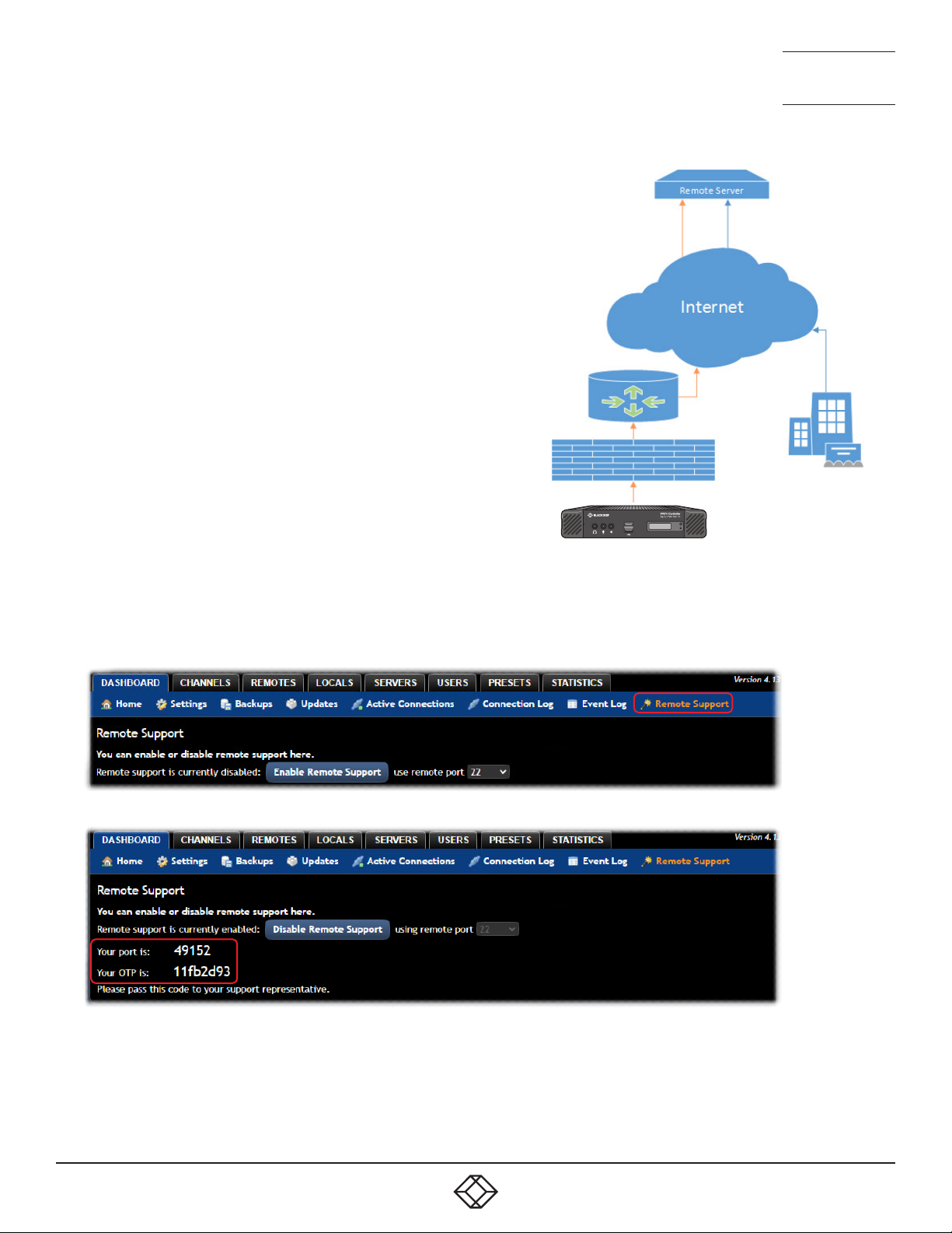
ENABLING REMOTE SUPPORT
F
The iPATH manager has a remote support feature that allows
technical support to connect should the need arise. It works by
establishing a secure SSL connection with a managed secure
server hosted on the internet. Using a reverse tunnel, technical
support can connect to the manager via the secure server.
Each support representative has their own unique SSL keys for
full traceability when making a remote connection. To protect
the manager against unauthorised access, Remote Support
is disabled by default. Access is only granted by Enabling
Support and giving the support representative a unique onetime password which is automatically generated each time it is
enabled.
This diagram shows how the feature works:
Note: There have been different versions of this Remote
Support feature where the behaviour varies slightly. We
recommend that you have the latest firmware installed.
irewall
Router
NEED HELP?
LEAVE T HE TEC H TO US
LIVE 24/7
TECHNICAL
SUPPORT
1.877.877.2269
Black Box
Support
1
2
• iPATH must be connected to a network which has internet access using Ethernet Port 2.
• Navigate to Dashboard -> Settings -> Network. You will need to configure an IP address, gateway and DNS for Ethernet Port 2.
• You will need to ensure that outbound port 22 is not blocked by the firewall or router to the internet. You can choose other
ports such as 80, 443, 53, 2222, 10222.
• Navigate to the Dashboard -> Remote Support tab on the iPATH admin Web UI and click on the Enable Remote Support button.
• The iPATH will show a port number and one-time password (OTP) which are required to remotely access the manager.
• If the port number changes after 1 minute, this means that either 1) The port is used by another Remote session or 2) The
manager has been unable to access the remote server. If port number continues to change, please check your network and
firewall settings.
• Please contact Black Box support, stating the port number and one-time password that you have been given. If you have
changed the admin password from the default, then please could you create a temporary administrator account so that we can
access the web interface if required.
40
1. 8 7 7. 87 7. 226 9 BLACKBOX.COM
Page 41
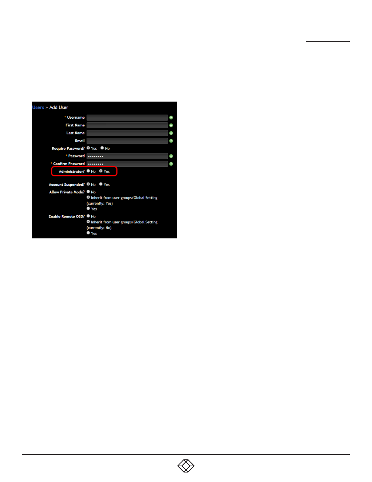
NEED HELP?
LEAVE T HE TEC H TO US
LIVE 24/7
TECHNICAL
SUPPORT
1.877.877.2269
Web Interface Access
During the Remote Support session, we may need access to the iPATH’s web interface. So that you do not need to reveal or
change your Admin password, please could you create a temporary user and set it as an iPATH Administrator. Please let us know
the user and password that you have created.
Troubleshooting
In the event that you do not see a port number, check the following:
• You have outbound port enabled on your firewall, typically 22, 443, 53, 2222 or 10222.
• There is only one gateway on the iPATH Manager, make sure that the gateway is correct. If you set the Ethernet port 2 to DHCP,
the gateway from the DHCP server is not used.
• Try manually assigning an IP address, subnet mask, gateway and DNS Setting to Ethernet Port 2.
1. 8 7 7. 87 7. 226 9 BLACKBOX.COM
41
Page 42

NEED HELP?
LEAVE T HE TEC H TO US
LIVE 24/7
TECHNICAL
SUPPORT
1.877.877.2269
THE CHANNELS TAB
The Channels tab provides access to all settings and options related directly to the video, audio and USB streams, collectively
known as channels, emanating from any number of locals.
Click the CHANNELS tab to view the initial View Channels page.
The various other Channels pages (e.g. Add Channel, View Channel Groups, etc.) are selectable within the blue section located
just below the tabs.
Search lters
The key fields (Name, Description, Location and Type) all provide a search filter to locate particular items
within long lists. Enter a full or partial search string into the appropriate filter box and then click to start
the search. Optionally use the buttons to invert the order of the listing.
The page will reload with the same pagination/sort order, but with the added search filter. It’s possible to
filter by several columns at once (e.g. search for all entries with “mac” in the name, and “mixed” in the description). Search terms
are case-insensitive. You can re-sort and paginate on filtered results without losing the filters.
To remove a filter, click the red cross next to the relevant filter, (you can also empty the search box and click again).
The Type column will either state Agility for connections which use an Agility local or RDP for virtual machine connections, which
do not require a physical local.
Channels > View Channels
This page lists all channels that currently exist within the iPATH system. A channel is automatically created for every local when
it is added and configured within the iPATH network. The new default channel for each added local will inherit the name of the
local. Such default names can be altered at any time and additionally, you can also create new channels manually, if necessary.
Within the list of channels, the Allowed Connections column indicates how each channel may be accessed by users. By default,
these settings are inherited from the global setting (configurable within the Dashboard > Settings page), however, each channel
can be altered as required. The icons denote the following connection rules:
Connection details inherited from the global setting
Video-Only
Shared
Exclusive
Private
The Channel Groups column shows to how many channel groups each channel belongs.
The Users column indicates how many users have permission to view each channel.
Actions that you can take within this page include:
• Create a new channel: Click the “Add Channel” option.
• Create a new channel group: Click the “Add Channel Group” option.
• Configure an existing channel: Click for the required channel.
• Clone an existing channel: Click to use the settings for the current channel as the basis for a new channel entry.
• Delete a channel: Click for the required channel.
• Delete multiple channels: Click the “Turn Batch Delete Mode On” button, the icons for all channels are replaced with tick
boxes. Tick the boxes of the channels that need to be deleted and then click the “Delete selected channels” button which
appears at the bottom of the page. When you are finished, click the “Turn Batch Delete Mode Off” button.
• View a channel group: Click the “View Channel Groups” button.
42
1. 8 7 7. 87 7. 226 9 BLACKBOX.COM
Page 43

NEED HELP?
LEAVE T HE TEC H TO US
LIVE 24/7
TECHNICAL
SUPPORT
1.877.877.2269
Channels > Add or Congure a Channel
From the View Channels page, you can add a new channel or configure an existing channel:
• To create a new channel: Click the “Add Channel” option.
• To configure an existing channel: Click for a channel.
The Add and Configure pages are similar in content.
Channel Name, Description and Location
These are all useful ways for you to identify the channel and its origins. A consistent naming and description policy is particularly
useful in large installations.
Video, Audio, USB, Serial and Digital Audio
These drop down boxes list all of the available streams from installed locals. When creating a channel, you can choose to take all
streams from the same local or from different ones, as required.
Notes:
• Where necessary, channels can be created without video, audio, USB and/or serial.
• Only one remote can use a local’s serial port at any time.
• Digital audio is the audio signal that is derived from video signals, such as DisplayPort connections and is only available on
certain dual port Agility models.
• When specifying dual-head video channels, you are recommended to avoid choosing video sources from two different locals.
Highly active video from two sources can result in video degradation and loss.
Sensitive
This will mark the channel as sensitive within the OSD channels list.
Override OSD Banner Position
Allows you to override the global setting for the positioning of the OSD banner for this channel.
Allowed Connection Modes
This section allows you to define the types of connection that you wish to permit users to make. You can define particular
individual or combined connection types to suit requirements.
Note: This setting for each channel acts as the final arbiter of whether exclusive access can actually be achieved. If you deny
exclusive access rights within this setting, then exclusive access for any user cannot take place for this channel, regardless of
settings made elsewhere.
• Inherit from global - uses the setting of the “Allowed Connection Modes” option within the Dashboard > Settings page.
• Set for this channel - permits you to choose modes manually:
• Video-Only: Allows users only to view the video output, the USB channel is denied.
•
Shared: Allows users to control a system in conjunction with other users.
• Exclusive: Grants exclusive control to one user while all others can simultaneously view and hear, but not control, the
output.
• Private: Allows a user to gain private access to a system, while locking out all others.
1. 8 7 7. 87 7. 226 9 BLACKBOX.COM
43
Page 44
NEED HELP?
LEAVE T HE TEC H TO US
LIVE 24/7
TECHNICAL
SUPPORT
1.877.877.2269
Group Membership
Groups provide a quick and easy way to manage settings for channels. By making a channel part of a particular group, the
channel automatically inherits the key settings of that group.
The group membership section displays existing channel groups in the left list (to which the current channel does not belong)
and the channel groups in the right list to which it does belong.
To add the channel to groups: Highlight one or more (use the CTRL key if selecting more than one) group names in the left list and
then click to add the name(s) to the right list.
Note: You can also include or exclude individual channels by double clicking on them.
To add the channel to all groups: Click to move all group names from the left to the right list.
To remove the channel from groups: Highlight one or more (use the CTRL key if selecting more than one) group names in the right
list and then click to move the name(s) back to the left list.
To remove the channel from all groups: Click to move all group names from the right to the left list.
Permissions
This section allows you to determine which users and user groups should be given access to this channel. Individual users and
user groups are handled within separate sub-sections, but both use the same method for inclusion and exclusion.
To include one or more users (or groups): Highlight one or more (use the CTRL key if selecting more than one) user/group names
in the left list and then click to add them to the right list.
To include all users (or groups): Click to move all user/group names from the left to the right list.
To remove one or more users (or groups): Highlight one or more (use the CTRL key if selecting more than one) user/group names
in the right list and then click to move them back to the left list.
To remove all users (or groups): Click to move all user/group names from the right to the left list.
44
1. 8 7 7. 87 7. 226 9 BLACKBOX.COM
Page 45
NEED HELP?
LEAVE T HE TEC H TO US
LIVE 24/7
TECHNICAL
SUPPORT
1.877.877.2269
Channels > Add or Congure Channel Group
Channel groups allow easy permission-granting for several channels at once. Permissions can be set to determine which users
can access channels within a channel group.
From the View Channels page, you can add a new channel group or configure an existing channel group:
• To create a new channel: Click the “Add Channel Group” option.
• To configure an existing channel: Click “the View Channel Groups” option and then click for a group.
The Add and Configure Channel Group pages are similar in content.
Channel Group Name and Description
These are all useful ways for you to identify the channel and its origins. A consistent naming and description policy is particularly
useful in large installations.
Group Membership
Allows you to determine which channels should be members of the group. By making a channel part of the group, each channel
automatically inherits the key settings of the group.
To add a channel to the group: Highlight one or more (use the CTRL key if selecting more than one) channel names in the left list
and then click to add the name(s) to the right list.
Note: You can also include or exclude individual channels by double clicking on them.
To add all channels to the group: Click to move all channel names from the left to the right list.
To remove a channel from the group: Highlight one or more (use the CTRL key if selecting more than one) channel names in the
right list and then click to move the name(s) back to the left list.
To remove all channels from the group: Click to move all channel names from the right to the left list.
Permissions
This section allows you to determine which users and user groups should be given access to channels within this group.
Individual users and user groups are handled within separate sub-sections, but both use the same method for inclusion and
exclusion.
To include one or more users (or groups): Highlight one or more (use the CTRL key if selecting more than one) user/group names
in the left list and then click to add them to the right list.
To include all users (or groups): Click to move all user/group names from the left to the right list.
To remove one or more users (or groups): Highlight one or more (use the CTRL key if selecting more than one) user/group names
in the right list and then click to move them back to the left list.
To remove all users (or groups): Click to move all user/group names from the right to the left list.
1. 8 7 7. 87 7. 226 9 BLACKBOX.COM
45
Page 46

NEED HELP?
LEAVE T HE TEC H TO US
LIVE 24/7
TECHNICAL
SUPPORT
1.877.877.2269
THE REMOTES TAB
The Remotes tab shows a paginated table of all remote devices within the iPATH network.
Click the REMOTES tab to view the initial View Remotes page.
The other Remotes pages (e.g. View Remote Groups, Add Remote Group, etc.) are selectable within the blue section located just
below the tabs.
Search lters
The key fields (Name, Description and Location) all provide a search filter to locate particular items within
long lists. Enter a full or partial search string into the appropriate filter box and then click to start the
search. Optionally use the buttons to invert the order of the listing.
The page will reload with the same pagination/sort order, but with the added search filter. It’s possible to
filter by several columns at once (e.g. search for all entries with “mac” in the name, and “mixed” in the description). Search terms
are case-insensitive. You can re-sort and paginate on filtered results without losing the filters.
To remove a filter, click the red cross next to the relevant filter, (you can also empty the search box and click again).
Remotes > View Remotes
The table shows the following information for each remote:
• Type and online status • Name
• IP address • Firmware revision
• Custom Settings (Inherited or Custom icons) • Remote Groups
• Presets • Users
• Description & Location • Manage (admin options - see below)
The Manage icons are as follows:
(Note: You can hover your mouse pointer over any icons to reveal additional information):
Configure device: Displays the “Configure Remote” page.
Reboot device: Allows you to reboot or reset a unit to its factory settings. A popup will ask which task you wish to carry out.
A reboot is useful if a device enters an unknown state. A reset will return the unit to its factory default state and reset its IP
address (the unit will retain any firmware updates that have been applied).
Identify unit: Causes the LED lights to flash on the front of the selected unit. An alert will be shown if the unit cannot be
contacted (e.g. if it is offline).
Delete device: Confirmation will be requested. You will need to factory-reset any devices that you wish to re-configure to
work with iPATH.
Connect to a channel: A list of available channels is shown, along with connection modes (Video-Only/Shared/Exclusive/
Private). The admin user can thus remotely change channel on any remote.
Disconnect: If a remote is currently connected to a channel, clicking the disconnect icon will end the connection, regardless
of who is connected. Hovering over the icon will show which user is connected, which channel they are connected to, and
when the connection was created.
Disconnect All: In the title bar above all of the other Manage icons, a Disconnect All control (if enabled within the main
settings page) allows all remotes to be collectively disconnected from their respective channels.
46
1. 8 7 7. 87 7. 226 9 BLACKBOX.COM
Page 47
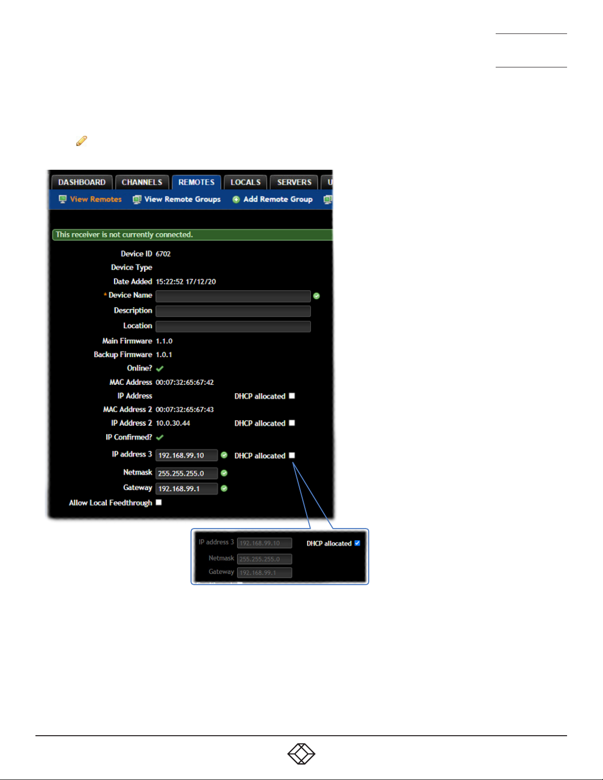
Remotes > Congure Remote
From the View Remotes page, you can configure details for a remote:
• Click for a remote.
Note: If the IP address of the remote is changed, the device will need to reboot itself.
NEED HELP?
LEAVE T HE TEC H TO US
LIVE 24/7
TECHNICAL
SUPPORT
1.877.877.2269
If the adjacent DHCP allocated
option is ticked, the fields will be
grayed out and configured by a
DHCP server.
Device ID / Type - Identity of the remote.
Device Name, Description and Location
These are all useful ways for you to identify the remote and its origins. A consistent naming and description policy is particularly
useful in large installations.
1. 8 7 7. 87 7. 226 9 BLACKBOX.COM
47
Page 48

NEED HELP?
LEAVE T HE TEC H TO US
LIVE 24/7
TECHNICAL
SUPPORT
1.877.877.2269
Main/Backup Firmware - The current rmware versions contained within the unit.
Online? - Current status of the remote.
MAC Address / 2 - Lists the xed network identiers for the single or double ports.
IP Address / 2 - Lists the single or dual IP addresses for the unit. If the DHCP options are ticked then the elds will be grayed out.
IP address 3 - (Selected models only) Lists the third IP address, netmask and gateway (for the RJ45 port) for the unit.
DHCP allocated - When ticked, the DHCP will assign the endpoint an available IP address from the DHCP pool. When unticked, it
allows you to manually specify an address to give to the Remote or Local. However, this is NOT a static IP address, but one that
the iPATH’s DHCP server will always issue to the endpoint on boot. Technically its a ‘DHCP Reserved IP address’.
Allow Local Feedthrough - (Selected models only) When selected, allows the remote to connect directly to a local source.
Login Required
• No: When selected, anyone can use a remote terminal and connect to a channel. The channels/permissions displayed to this
anonymous user are those that are set for the “anonymous user” that is defined within the Dashboard > Settings page.
• Inherit from Remote Groups: When selected, the requirement for user login will be determined by the “Login Required” settings
within the Remote Groups to which this unit belongs:
• If ANY of the remote groups (to which this remote belongs) are set as “Login Required = Yes”, this remote will require login.
• If ANY of the remote groups (to which this remote belongs) are set as “Login Required = Inherit...” and the global setting is
“login required = yes”, then this remote will require login.
• If ALL remote groups (to which this remote belongs) are set as “Login Required = No”, then this remote will NOT require
login.
• Yes: When selected, a user will need to login with the username and password defined in the “Users” section. They will only be
allowed to login if they have been granted permission to access that particular remote.
Remote OSD Alerts
Determine the required setting for pop up OSD alerts: Inherit, No or Yes.
Show Current Channel
When selected, shows the currently connected channel as an overlay.
OSD Banner Position
Allows you to determine the position of the OSD banner on each user’s screen - or use the global settings.
Touch show OSD enable
Determines whether the OSD can be shown on a touch screen device when supported by certain Agility devices.
USB Connector to Monitor number mapping
Allows you to share the various emulated USB ports between the connected video displays. This option uses the global setting by
default.
Keyboard Country
Select the country code of the keyboard connected to the remote.
Audio Input Type
Select the required audio input type.
48
1. 8 7 7. 87 7. 226 9 BLACKBOX.COM
Page 49

NEED HELP?
LEAVE T HE TEC H TO US
LIVE 24/7
TECHNICAL
SUPPORT
1.877.877.2269
Monitor 1 / 2 Settings
Video Compatibility Check
This reads the EDID from the attached monitor(s) and determines whether they are capable of displaying the selected video
mode before connecting a channel. This prevents the remote showing a black screen and the user being locked out, for instance
because a dual link resolution has been selected to display on a single link monitor.
Force 60Hz
If enabled, the remote frame rate is held at 60Hz regardless of the video input frame rate. The Video Switching options (below)
cannot be altered when this option is enabled.
Video Switching
Provides two options for video switching:
• Fast Switching (default state) - Retains the same frame rate (at either 50Hz or 60Hz) depending upon which video resolution
was displayed first.
• Match Frame Rate - Follows the source frame rate and will change the frame rate every time this changes even if the video
resolution doesn’t change. If you have one remote switching between 1920x1080@60Hz and 1920x1080@50Hz then this
setting will change the frame rate from 60Hz to 50 Hz every time that you switch.
Audio Compatibility Check
This reads the EDID from the attached monitor and determines whether the monitor is capable of processing the selected digital
audio mode before connecting a channel.
Group Membership
To facilitate collective permission-granting for numerous remotes, a remote can belong to one or more remote groups. Any
permissions applied to the remote group are inherited by all remotes that are included within the remote group. For example,
multiple remotes can be made available to a user by placing them all in a remote group and then granting the user permission to
use that remote group.
Permissions
This is hidden by default as, by default, all users have access to all remotes. You can deny access to particular remotes for a user
in this section. However, be aware that users who are included within user groups may have access to the same remotes via their
groups.
Advanced Port Features
This section allows you to determine USB port behaviour for use with certain USB devices.
The default is no reserved ports, Merging enabled and no feature code (or Quirk) set. It is recommended that these are left at the
default settings and are only changed under advice from a Black Box support engineer.
For each of the four USB ports on the remote, certain rules can be applied depending upon the USB device connected.
If you have reserved USB ports on the local, you can select which USB port to use for a particular device.
You can turn off USB merging for a particular port. This will slow down switching as the USB device will be enumerated every
time that you switch.
You can also enter an advanced feature if it is necessary for your USB device. The drop down lists the feature codes for some
known USB devices. Otherwise please contact your local FAE for advice.
1. 8 7 7. 87 7. 226 9 BLACKBOX.COM
49
Page 50

NEED HELP?
LEAVE T HE TEC H TO US
LIVE 24/7
TECHNICAL
SUPPORT
1.877.877.2269
USB Settings
Remote ID / Name - Identity of the remote.
HID Only
This option allows you restrict USB devices to allow only HID (mice, keyboards, tablets, touchscreens, etc.) devices to be
connected to the remote(s).
Block Mass Storage
This option allows you to prevent the use of USB mass storage devices at the remote(s).
The HID Only and Block Mass Storage options both affect how USB devices are supported at the remote(s). Their use in
combination can produce the following results:
HID Only Block Mass Storage Outcome
No No No USB restrictions
Yes No
No Yes
Yes Yes
Allow only HID devices
(Mass storage devices are also blocked)
Exclude mass storage devices but
allow other USB peripherals (e.g. mice,
keyboards, tablets, touchscreens, etc.)
Allow only HID devices
(Mass storage devices are blocked)
Disable Isochronous Endpoint OSD Alerts
When an isochronous USB device is connected to the remote there will no longer be a warning message. Agility units do not
support isochronous devices.
Enable Isochronous Endpoint Attach
Some USB devices combine many USB devices behind a USB hub. e.g a keyboard with audio support. By enabling this option,
devices will be allowed to connect to Agility remotes, however, the isochronous part (e.g. the audio component) of the devices will
not work.
Remotes > Congure New Remote
This page is displayed whenever a new remote is added to the network.
The IP Address 1 field, showing the IP address that has been assigned by DHCP. Before iPATH can add the device into its
database, a new IP address must be added to IP Address 1. This is the system IP address and applies equally for all Agility series.
Agility Dual units have a secondary link port which can be used for bandwidth doubling and/or redundancy. The IP address 2 field
is for the second (Teaming) port. In order to use the second port, IP address 2 field must be given a valid IP address. For Agility
units, this field will remain blank.
50
1. 8 7 7. 87 7. 226 9 BLACKBOX.COM
Page 51

NEED HELP?
LEAVE T HE TEC H TO US
LIVE 24/7
TECHNICAL
SUPPORT
1.877.877.2269
Remotes > Add Remote Group or Congure Group
From the View Remote Groups page, you can create a new group or configure an existing group:
• To create a new group: Click the “Add Remote Group” option.
• To configure an existing group: Click for a group.
The Add and Configure pages are similar in content.
Remote Group Name and Description
The group name must be populated with a name up to 45 characters. A consistent naming and description policy is particularly
useful in large installations.
Login Required
• No: When selected, anyone can use a remote terminal and connect to a channel. The channels/permissions displayed to this
anonymous user are those that are set for the “anonymous user” defined within the Dashboard > Settings page.
• Inherit from global setting: When selected, the requirement for user login will be determined by the “Login Required” setting
within the Dashboard > Settings page.
• Yes: When selected, a user will need to login with the username and password defined in the “Users” section. They will only be
allowed to login if they have been granted permission to access devices in the remote group.
Enable Remote OSD Alerts
Determine the required setting for pop up OSD alerts: Inherit, No or Yes.
The next fields are the USB settings.
Note: USB port reservation and advanced USB features will be added to future releases of the iPATH management system.
Show Current Channel
When enabled, the name of the channel currently being viewed will be shown on screen.
OSD Banner Position
Allows you to determine the position of the OSD banner on each user’s screen.
Touch show OSD enable
Determines whether the OSD can be shown on a touch screen device when supported by certain Agility devices.
USB Connector to Monitor number mapping
Allows you to share the various emulated USB ports between the connected video displays. This option uses the global setting by
default.
Enable Video Compatibility Check
When enabled, this option reads the EDID from the attached monitor and determines whether it is capable of displaying the
selected video mode before connecting a channel. This prevents the remote showing a black screen and the user being locked
out because a dual link resolution has been selected to display on a single link monitor.
Enable Audio Compatibility Check
Applicable only to remotes which are capable of processing multichannel digital audio via their DisplayPort connections. When
enabled, this option reads the EDID from the attached monitor/audio system and determines whether the remote’s current audio
setting (e.g. 2 Channel, 6 Channel, 8 Channel) is capable of correctly playing the selected audio (e.g. Stereo, 5.1 or 7.1) mode
before connecting a channel.
1. 8 7 7. 87 7. 226 9 BLACKBOX.COM
51
Page 52

NEED HELP?
LEAVE T HE TEC H TO US
LIVE 24/7
TECHNICAL
SUPPORT
1.877.877.2269
Force 60Hz
If enabled, the remote frame rate is held at 60Hz regardless of the video input frame rate. The Video Switching options (below)
cannot be altered when this option is enabled.
Video Switching
Provides two options for video switching:
• Fast Switching (default state) - Retains the same frame rate (at either 50Hz or 60Hz) depending upon which video resolution
was displayed first.
• Match Frame Rate - Follows the source frame rate and will change the frame rate every time this changes even if the video
resolution doesn’t change. If you have one remote switching between 1920x1080@60Hz and 1920x1080@50Hz then this
setting will change the frame rate from 60Hz to 50 Hz every time that you switch.
USB Settings - see USB Settings.
Group Membership
This section allows you to easily include or exclude individual remotes for this group. All relevant group permissions will be
applied to all remotes that are included within the group. Remotes that are not currently included in this group within the left list
and those remotes that are included within the right list.
To add a remote to this group: Highlight one or more (use the CTRL key if selecting more than one) remote names in the left list
and then click to add the name(s) to the right list.
To add all remotes to the group: Click to move all remote names from the left to the right list.
To remove a remote from the group: Highlight one or more (use the CTRL key if selecting more than one) remote names in the
right list and then click to move the name(s) back to the left list.
To remove all remotes from the group: Click to move all remote names from the right to the left list.
Permissions
This is hidden by default because all users have access to all remotes. You can deny access to the remote group, however, be
aware that users who are included within user groups may have been given access to the remote group via their user groups.
Remotes > Update Firmware
Click this option to go straight to the Dashboard > Updates page.
See Dashboard > Updates for more details.
52
1. 8 7 7. 87 7. 226 9 BLACKBOX.COM
Page 53
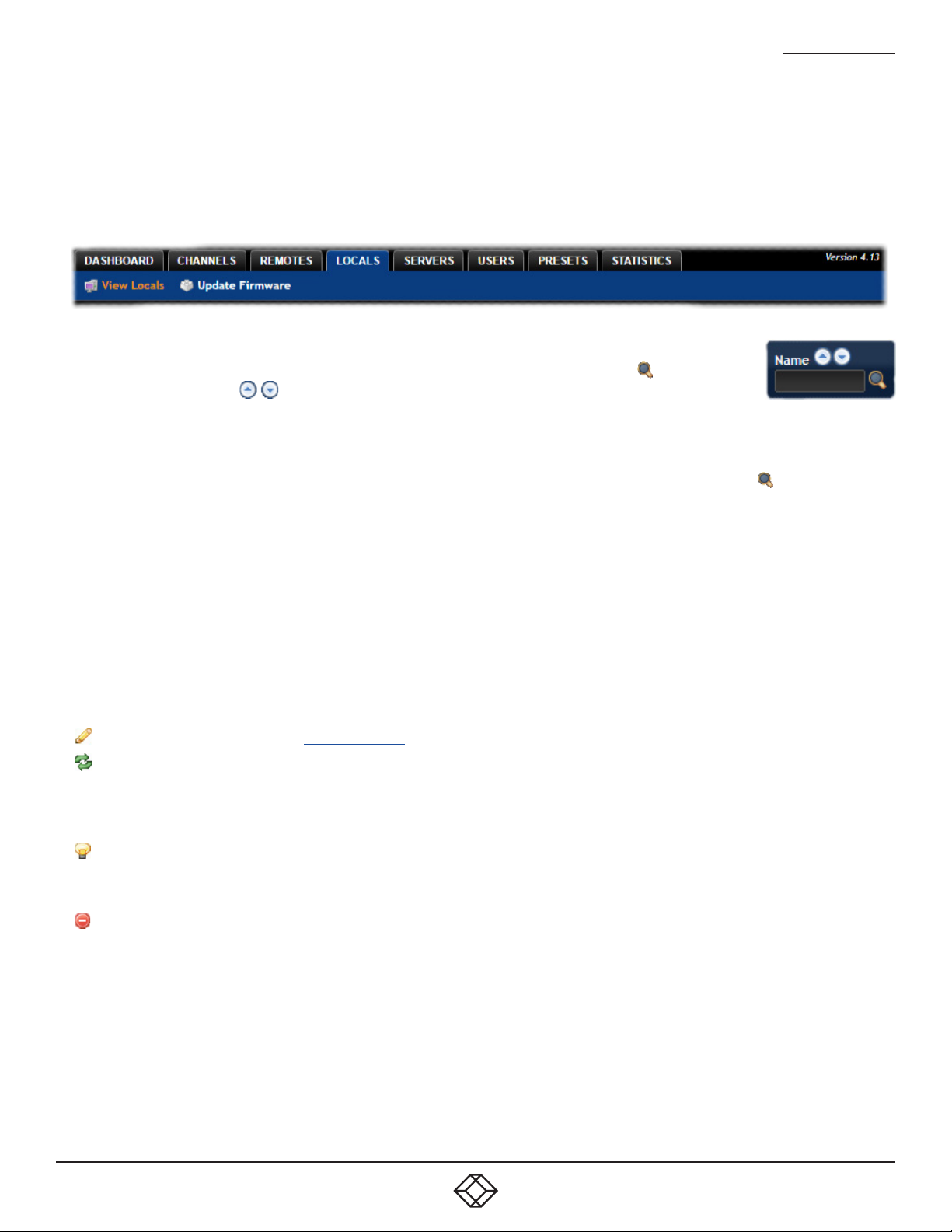
NEED HELP?
LEAVE T HE TEC H TO US
LIVE 24/7
TECHNICAL
SUPPORT
1.877.877.2269
THE LOCALS TAB
The Locals tab shows a paginated table of all local devices within the iPATH network.
Click the LocalS tab to view the locals page.
Search lters
The key fields (Name, Description and Location) all provide a search filter to locate particular items within
long lists. Enter a full or partial search string into the appropriate filter box and then click to start the
search. Optionally use the buttons to invert the order of the listing.
The page will reload with the same pagination/sort order, but with the added search filter. It’s possible to
filter by several columns at once (e.g. search for all entries with “mac” in the name, and “mixed” in the description). Search terms
are case-insensitive. You can re-sort and paginate on filtered results without losing the filters.
To remove a filter, click the red cross next to the relevant filter, (you can also empty the search box and click again).
Locals > View Locals
The table shows the following information for each local:
• Type and online status • Name
• IP address • Firmware revision
• Custom Settings (Inherited or Custom icons) • Presets
• Channels (attributed to each local) • Description & Location
• Manage (admin options - see below)
The Manage icons are as follows:
(Note: You can hover your mouse pointer over any icons to reveal additional information):
Configure device: Displays the “Configure Local” page.
Reboot device: Allows you to reboot or reset a unit to its factory settings. A popup will ask which task you wish to carry out.
A reboot is useful if a device enters an unknown state. A reset will return the unit to its factory default state and reset its IP
address (the unit will retain any firmware updates that have been applied).
Note: This icon is not present on virtual machine entries.
Identify unit: Causes the LED lights to flash on the front of the selected unit. An alert will be shown if the unit cannot be
contacted (e.g. if it is offline).
Note: This icon is not present on virtual machine entries.
Delete device: Confirmation will be requested. You will need to factory-reset any devices that you wish to re-configure to
work with iPATH.
1. 8 7 7. 87 7. 226 9 BLACKBOX.COM
53
Page 54

NEED HELP?
LEAVE T HE TEC H TO US
LIVE 24/7
TECHNICAL
SUPPORT
1.877.877.2269
Locals > Congure Local
In the list of locals, when you click for a particular entry, this page lists information about the unit and allows numerous
settings to be configured.
Device ID / Type - Identity of the local.
Device Name, Description and Location
These are useful identifiers for the local unit and its exact location. These become even more valuable as the number of locals
within the system increases.
Main/Backup Firmware
The current firmware versions contained within the unit.
Online?
Current status of the remote.
MAC Address / 2
Lists the fixed network identifiers for the single or double ports.
IP Address / 2
Lists the single or dual IP addresses for the unit. If the DHCP options are ticked then the fields will be grayed out.
Video 1/2 Multicast IPs
Lists the IP addresses that will be used for distributing video signals when multicasting.
Audio Multicast IPs
Lists the IP addresses that will be used for distributing audio signals when multicasting.
Enable Dummy Boot Keyboard
It is often necessary to have a keyboard reported at start up. This setting means that a “Virtual Keyboard” is always reported to
the USB host. It may be necessary to disable this for use with some KVM switches.
Enable Audio
Determines the status of the audio feed from the local.
USB Speed
Select Low/full speed or High speed USB operation.
USB Hub Size
Select either a 13 or 7 port USB hub. This determines the number of USB devices that can be connected to a single Local.
Peak Bandwidth Limiter
The local will use as much of the available network bandwidth as necessary to achieve optimal data quality, although typically
the local will use considerably less than the maximum available. In order to prevent the local from ‘hogging’ too much of the
network capacity, you can reduce this setting to place a tighter limit on the maximum bandwidth permissible to the local. Range:
1 to 100%.
54
1. 8 7 7. 87 7. 226 9 BLACKBOX.COM
Page 55

NEED HELP?
LEAVE T HE TEC H TO US
LIVE 24/7
TECHNICAL
SUPPORT
1.877.877.2269
Transparent USB Bandwidth Limit
In order to prevent the local from ‘hogging’ too much of the network capacity, you can reduce this setting to place a limit on the
maximum USB bandwidth permissible to the local. Range: 1 to 100% (which equates to 1 to 480Mbps).
Video Port 1/2 Settings
These two sections allow you to directly adjust various key video controls within the local in order to obtain the most efficient
operation taking into account connection speeds and the nature of the video images sent by that local.
Magic Eye
Determines whether the Magic Eye feature should be enabled on certain Agility locals. Magic Eye works to overcome the issues with
increased bandwidth usage caused by ‘dithering’ techniques used on some computers, such as Apple Macs. See the Agility dual
user guide for more details.
EDID
Determines how the video configuration details should be determined: Either harvested from the connected display screens (USE
CONNECTED MONITOR’S EDID) or by selecting a static fixed EDID setting from the list (e.g. GENERIC 16:9, 1920x1080 HD1080,
1600x1200 UXGA, etc.). Using a fixed EDID setting can significantly speed up video switching times as EDIDs do not need to be
checked, however, all of the installed monitors need to support the chosen resolution. Where EDIDs are checked, enabling EDID
Optimisation (below) can help to regain some of the switching speed.
Note: Care must be taken when selecting a Dual Link Video resolution (e.g. 2560x1600) as certain Agility units do not support Dual
Link Video resolutions. In the case of a Dual Link EDID being set in the Global settings, no EDID will be set on Video port 2 of dual port
Agility locals.
Dynamic Range EDID
For Agility devices which support HDR, this option can be used to grant permission to go beyond the standard SDR8 setting and
use SDR10 or HDR10 when the connected host and video displays support 10bpc color depths.
EDID optimisation
When this option is enabled, the local will compare the native resolution settings of its monitor(s) when switching. If a monitor
has the same native resolution as the previous one, the new EDID is not sent to the graphics card. This speeds up switching as
the graphics card does not have to go through a hotplug detect routine when a new remote is switched to that channel. If the new
remote has a monitor with a different native resolution, then the EDID will be updated to allow for a change in video mode.
Audio EDID
For locals which support digital audio via the DisplayPort connection(s), this setting determines how the audio should be
configured: (USE CONNECTED MONITOR’S EDID) or a static setting: NONE, 2 CHANNEL (Stereo), 6 CHANNEL (surround 5.1) or
8 CHANNEL (surround 7.1). Using a fixed EDID setting can significantly speed up switching times as EDIDs do not need to be
checked, however, all of the installed audio devices need to support the chosen format. Where EDIDs are checked, enabling Audio
EDID Optimisation (below) can help to regain some of the switching speed.
Audio EDID Optimisation
When enabled, locals will compare the digital audio settings when switching. If a remote’s digital audio settings are the same as
the previous one, the new EDID is not sent to the host system. This speeds up switching as the host system does not need to go
through a hotplug detect routine when a new remote is switched to that channel. If the new remote uses a different audio setting,
then the EDID will be updated to allow for a change in audio mode.
1. 8 7 7. 87 7. 226 9 BLACKBOX.COM
55
Page 56

NEED HELP?
LEAVE T HE TEC H TO US
LIVE 24/7
TECHNICAL
SUPPORT
1.877.877.2269
Hot Plug Detect Control
Determines whether to enable hot plug detection for monitors. By default this is enabled.
Hot Plug Detect Signal Period
By default this is set at 100ms, which is sufficient for most graphics cards. Occasionally it may be necessary to adjust this. A
Black Box engineer will advise if necessary.
Background Refresh
The local sends portions of the video image only when they change. In order to give the best user experience, the local also sends
the whole video image, at a lower frame rate, in the background. The Background Refresh parameter controls the rate at which
this background image is sent. The default value is ‘every 32 frames’, meaning that a full frame is sent in the background every
32 frames. Reducing this to ‘every 64 frames’ or more will reduce the amount of bandwidth that the local consumes. On a hightraffic network this parameter should be reduced in this way to improve overall system performance. Options: Every 32 frames,
Every 64 frames, Every 128 frames, Every 256 frames or Disabled.
Compression Level
The newer AFZ+ codec complements the existing AFZ codec by providing greater compression for increased speed where pixel
perfect results are not the primary focus. The local video configuration page allows you to choose the required compression
mode. Choices are:
• ‘Pixel perfect’ - only uses pixel perfect AFZ,
• ‘Adaptive’ - guarantees frame rate, builds to pixel perfect,
• ‘Smoothest video’ - forces the maximum compression, or
• ‘Advanced’ - allows you to choose the minimum and maximum compression modes:
1 = ‘AFZ only (pixel perfect),
2 = ‘AFZ+ Minimum compression’,
3 = ‘AFZ+ Middle compression’, or
4 = ‘AFZ+ Maximum compression’.
Frame Skipping
Frame Skipping involves ‘missing out’ video frames between those captured by the local. For video sources that update only
infrequently or for those that update very frequently but where high fidelity is not required, frame skipping is a good strategy for
reducing the overall bandwidth consumed by the system. Range: 0 to 99%.
Serial Settings
Serial Parity, Serial Data Bits, Serial Stop Bits, Serial Speed
This group of settings allows you to define the key parameters for the AUX port of the local so that it matches the operation of the
device attached to it.
56
1. 8 7 7. 87 7. 226 9 BLACKBOX.COM
Page 57

NEED HELP?
LEAVE T HE TEC H TO US
LIVE 24/7
TECHNICAL
SUPPORT
1.877.877.2269
THE SERVERS TAB
The Servers tab shows a table of all servers within the iPATH network.
Click the SERVERS tab to view the page.
For installations that require greater redundancy, it is possible to have two or more iPATH servers running on the same subnet.
If used on multiple subnets it is possible to have two or more servers on each subnet. If the primary server fails then alternative
servers with the same database can take over until the primary unit recovers.
Each server entry will have one of five possible states within the Rôle column:
• Unconfigured The server is a factory fresh device or has performed a full factory reset. This does not yet have a proper role.
• Solo This is a server acting as a standalone iPATH Agility Controller. If there is only going to be one iPATH Agility Controller on
the subnet, this is the Rôle that should be used.
• Primary The server is configured as a fully functional iPATH from which a back-up server can be slaved.
• Backup If more than one server is on the same subnet this is a primary backup configuration. If there are three servers on the
same subnet you will have one primary and two backups.
• Satellite This is the role of a server on a different subnet to the primary. If you have multiple servers on the different subnet
these would all be called satellite servers. If you had a configuration with two servers on Vlan 1, two servers on Vlan 2 and 1
server on Vlan 3. iPATH would report 1 primary on Vlan 1, 1 Backup on Vlan 1, 2 satellites on Vlan 2 and 1 satellite on Vlan3.
Each server entry will also show one of six entries within the Status column:
• Active This server is functioning as an iPATH Agility Controller and is administering Agility devices. Primary or Solo servers
with this status are fully functional iPATH servers that will accept network configuration changes. A Backup server with this
status is functioning as an Active Primary. It will execute channel changes, but will not accept network configuration changes.
• Standby This server is currently maintaining its database as a copy of the primary in readiness to take over if necessary.
• Offline This server should be maintaining a copy of the primary’s database, but is not doing so. The offline status of a satellite
server means that it is ready to take over Agility units on its own subnet if necessary, but that it cannot communicate with the
primary server.
• Initialising This is the initial status upon start up. This should not persist beyond the initial start up procedure.
• Quiescent This is an inactive server on the network. It will not function without remedial action from its system administration.
A typical reason for this is the presence of another server on the network blocking its configured role. i.e. two servers are
configured as a primary on the same subnet.
• Failed This server has suffered a serious internal failure.
1. 8 7 7. 87 7. 226 9 BLACKBOX.COM
57
Page 58

NEED HELP?
LEAVE T HE TEC H TO US
LIVE 24/7
TECHNICAL
SUPPORT
1.877.877.2269
Servers > Congure Server
When you click for a particular server, this page lists information about the unit and allows several basic settings to be
configured.
Server ID - Identity number of the server.
Rôle
Allows you to change the server’s function between primary and solo (see descriptions left).
Status
See above.
Name, Description and Location
These are useful identifiers for the server unit and its exact location. These become even more valuable as the number of servers
within the system increases.
Ethernet Port 2
Where a second Ethernet port is available and the primary server has its second interface configured, this option allows you to
determine how the addressing for the second port on this server should be derived. For further details, see the Ethernet port 2
explanation in the Dashboard > Settings > Network section.
For details about setting up server redundancy, please see Appendix C - Redundant servers: Setting up and swapping out.
58
1. 8 7 7. 87 7. 226 9 BLACKBOX.COM
Page 59
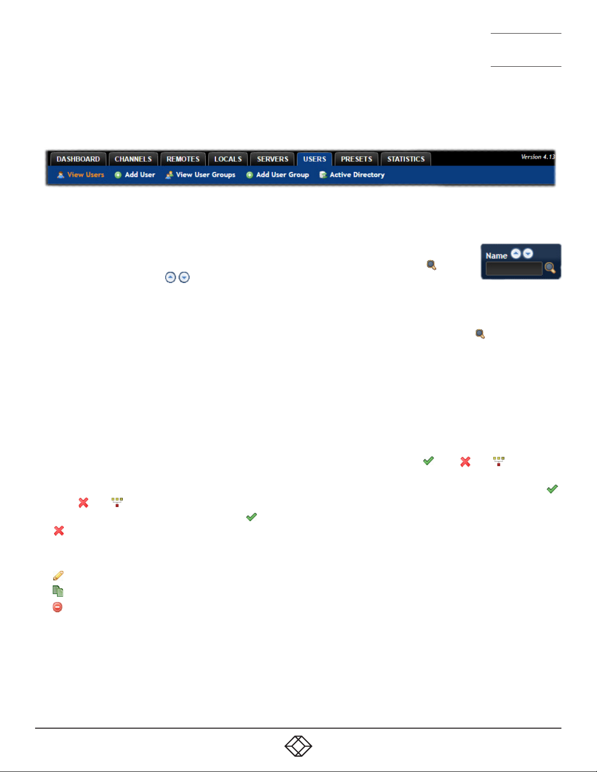
NEED HELP?
LEAVE T HE TEC H TO US
LIVE 24/7
TECHNICAL
SUPPORT
1.877.877.2269
THE USERS TAB
The Users tab shows a paginated table of all users within the iPATH network. Within the list, the admin user is always present and
cannot be deleted - in order to avoid being locked out of the iPATH system.
Click the USERS tab to view the initial View Users page.
The other user pages (e.g. Add User, View User Groups, etc.) are selectable within the blue section located just below the tabs.
Search lters
The key fields (Username, First Name and Last Name) all provide a search filter to locate particular items
within long lists. Enter a full or partial search string into the appropriate filter box and then click to start
the search. Optionally use the buttons to invert the order of the listing.
The page will reload with the same pagination/sort order, but with the added search filter. It’s possible to
filter by several columns at once (e.g. search for all entries with “B” in the Username, and “Smith” in the Last Name). Search terms
are case-insensitive. You can re-sort and paginate on filtered results without losing the filters.
To remove a filter, click the red cross next to the relevant filter, (you can also empty the search box and click again).
Users > View Users page
The table shows the following information for each user:
• AD - indicates whether the user was imported from Active Directory
• Username • First Name • Last Name
• User Groups - the number of user groups to which the user belongs
• Channels - the number of channels to which the user has access
• Remotes - the number of remotes to which the user has access
• Allow Private? - indicates whether the user is permitted to access channels in private mode ( - Yes, - No, - Inherited
setting from user groups)
• Remote OSD? - indicates whether the user is permitted to gain OSD access to remote remotes in order to change channels (
- Yes, - No, - Inherited setting from user groups)
• Suspended - indicates the user account status ( - User is suspended,
- User account is active, i.e. not suspended)
• iPATH Admin - indicates whether the user has admin privileges
The Manage icons are as follows:
Configure user: Displays the “Configure User” page.
Clone user: Create a complete copy of the currently selected user entry.
Delete user: Confirmation will be requested.
1. 8 7 7. 87 7. 226 9 BLACKBOX.COM
59
Page 60

NEED HELP?
LEAVE T HE TEC H TO US
LIVE 24/7
TECHNICAL
SUPPORT
1.877.877.2269
Users > Add User or Congure User page
From the View Users page, you can add a new user or configure an existing user:
• To add a user: Click the “Add User” option.
• To configure an existing user: Click for a user.
The Add and Configure pages are similar in content.
Username
The username is mandatory and must be unique within the iPATH installation.
Note: If a user is synced with Active Directory, it is not possible to change the Username, First/Last Name, Password, or User
Group membership. These items must be edited on the Active Directory server and the changes will filter through to iPATH the
next time a sync takes place with Active Directory.
First Name, Last Name and Email
The First Name, Last Names and Email address entries are optional but are advisable within an installation of any size or one that
will be administered by more than one person.
Require Password
Determines whether the chosen user must enter a password to gain access to channels and/or iPATH admin system.
Password
The password is required for logging into a channel and/or for logging into the iPATH admin system, if the user is to be granted
admin privileges.
iPATH Administrator?
When set to Yes, the user is granted privileges to login to the iPATH admin system and make changes.
Account Suspended?
Allows the admin user to temporarily prevent the user from logging in without the need to delete the whole account.
Allow Private Mode?
Defines whether the user is able to connect to channels privately (locking out other users during a session). When this is set
to “Inherit from User Groups/Global Setting”, if ANY user-group that a user is a member of is granted permission to connect
privately, then the user will have permission to connect privately. Note: It is an additional requirement that the channel being
accessed by the user, must also permit private access.
Enable Remote OSD?
This option determines whether the chosen user should be permitted to use the remote OSD functionality which permits access
to remote remotes in order to change channels or presets even though a user has not logged into those remotes. Please see
Using the Remote OSD feature for details.
Group Membership
This section defines the user groups to which the user will be a member. Any permissions applied to the user group are inherited
by all users in the user group. User groups to which the user is not currently a member are shown in the left list and those to
which the user is a member are shown within the right list. See Including and excluding a user... on the next page for details
about including and excluding group membership.
Permissions
This section defines to which channels and/or channel groups the user should have access. Note: Only the channels for which a
user is given permission to access will appear within their channel list.
See Including and excluding a user... on the next page for details about including and excluding channels and/or channel groups.
Remote and Remote Group Permissions
Remote and Remote Group Permissions are hidden by default because all users are initially granted permission to use all
remotes. If desired, permission to use a remote and/or remote group may be withdrawn from a user by revealing this section.
60
1. 8 7 7. 87 7. 226 9 BLACKBOX.COM
Page 61

NEED HELP?
LEAVE T HE TEC H TO US
LIVE 24/7
TECHNICAL
SUPPORT
1.877.877.2269
Users > Add User Group or Congure Group page
From the View User Groups page, you can create a new group or configure an existing group:
• To create a new group: Click the “Add User Group” option.
• To configure an existing group: Click for a group.
The Add and Configure pages are similar in content.
User Group Name
The User Group name must be unique within the iPATH installation.
Allow Private Mode?
Defines whether the users within the group will be able to connect to channels privately (locking out other users during the
session). When this is set to “Inherit from global setting”, the setting for the “Grant all users private access” option (within
Dashboard > Settings) will be applied. Note: The final arbiter of whether any user can gain private access is always whether the
channel being accessed is also set to allow private connections.
Enable Remote OSD?
Determines whether members of the chosen user group should be permitted to gain OSD access to remote remotes in order to
change channels.
Group Membership
This section allows you to select which users should be members of the group. Any permissions applied to the user group
are inherited by all users in the user group. Users who are not currently members are shown in the left list and those who
are members are shown within the right list. See Including and excluding a user... on the right for details about including and
excluding group membership.
Permissions
This section defines to which channels and/or channel groups the user within this group should have access. Note: Only the
channels/channel groups for which a user is given permission to access will appear within their channel list.
See Including and excluding a user... right for details about including and excluding channels and/or channel groups.
Remote and Remote Group Permissions
Remote and Remote Group Permissions are hidden by default because all users/user groups are initially granted permission to
use all remotes. If desired, permission to use a remote and/or remote group may be withdrawn from members of this user group
by revealing this section.
Including and excluding a user within group or channels
The Group Membership and Permissions section use the same method to determine inclusion and exclusion:
To add the user to a group or grant access to a channel: Highlight one or more (use the CTRL key if selecting more than one) of the
entries in the left list and then click to add them to the right list (you can also double-click on an entry to quickly add it).
To add the user to all groups or grant access to all channels: Click to move all entries from the left to the right list.
To remove the user from a group or channel: Highlight one or more (use the CTRL key if selecting more than one) entries in the
right list and then click to move them back to the left list (you can also double-click on an entry to quickly remove it).
To remove the user from all groups or channels: Click to move all entries from the right to the left list.
1. 8 7 7. 87 7. 226 9 BLACKBOX.COM
61
Page 62

NEED HELP?
LEAVE T HE TEC H TO US
LIVE 24/7
TECHNICAL
SUPPORT
1.877.877.2269
Users > Active Directory
To simplify integration alongside existing systems within organisations, iPATH can be synchronized with an LDAP/Active
Directory server. This allows a list of users (and user groups), together with usernames and group memberships to be quickly
imported and kept up to date.
Initial conguration
The basic Active Directory (AD) server details are defined in the Dashboard > Settings page. Once configured, the Users > Active
Directory page (called “Import Users from Active Directory”) will allow you to scan the AD server for a list of folders and users/
groups within those folders.
Choosing users and groups
Once scanned, the “Import Users from Active Directory” page shows all folders that are available on the AD server.
1 Use the “Include Users” and “Include Groups” checkbox columns on the right hand side of the folder lists to select which items
to import (with optional additional LDAP filters where necessary).
• If an AD user was not in the iPATH user database, they will be imported.
• If an AD user is already in the iPATH user database, they are kept.
• If an AD user is NOT marked for import/sync from the AD import page, and they already exist in the iPATH user database,
they will be removed from the iPATH user database during the sync operation.
IMPORTANT: It is thus vital to ensure that all users you want in the iPATH system are always selected for import/sync,
otherwise they will be removed.
2 Choose the required “Re-Synchronize” interval. Choices are Never, Hourly, Daily or Weekly.
3 You can choose to synchronize immediately or to preview the results of your settings:
• Click the “Preview” button to view the list of users that will be added/updated/removed on this synchronization. Once
previewed, you can either go ahead with the sync or return to the filter page and edit your settings.
• Click the “Save & Sync” button to synchronize the selected items into the iPATH user database.
Active Directory Tips
• A backup schedule is recommended so that any changes on the AD server are carried across to the iPATH Agility Controller
regularly. You can choose from hourly/daily or weekly syncs. The settings/filters saved on this screen will be applied to each
subsequent sync, ensuring that your list of users is kept accurate.
• To temporarily remove a particular user from iPATH access, without having to make complicated LDAP filters, simply edit the
iPATH user to be suspended (see Users > Add User or Configure User page). Even though they will continue to be imported/
synced from AD, they will be prevented from logging on.
• All LDAP filters should be self-contained, e.g: (!(cn=a*))
• Be sure to save any changes made to the sync settings before clicking the “sync-now” option. Otherwise, the next scheduled
sync operation will overwrite any user changes you made in your “sync-now”.
• User groups are only imported from AD to iPATH if they contain users that are set to be imported too (i.e. a group will not be
imported, even if it contains users, unless its users match the sync filters).
Note: If a group contains more than 1499 users, then the group is returned as empty.
• Associations between users and user groups can only be made on the AD server - it is not possible to edit user/user-group
membership for AD users/groups on the iPATH Agility Controller.
• Users and groups are technically “synchronized” rather than “imported” - each time a sync takes place, details are updated and
if a user no longer matches the sync filters, they will be removed from the iPATH user list.
62
1. 8 7 7. 87 7. 226 9 BLACKBOX.COM
Page 63
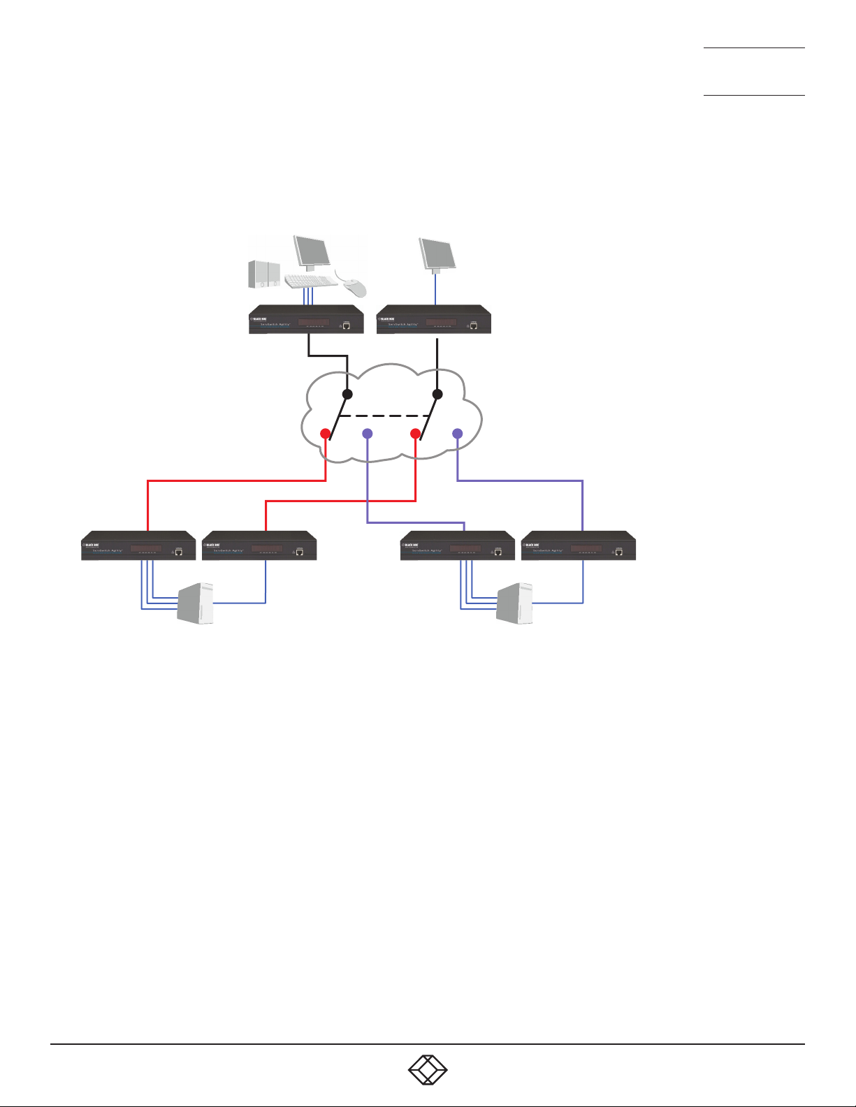
NEED HELP?
A B
LEAVE T HE TEC H TO US
LIVE 24/7
TECHNICAL
SUPPORT
1.877.877.2269
THE PRESETS TAB
Presets enable multiple actions to be pre-defined so that they can be initiated with a single action. This feature is particularly
useful when switching multiple Agility units, such as in the example below where multiple video heads need to be switched in
unison between different server systems.
The preset allows multiple
Agility remotes to be switched
between locals using a single
action.
According to how a preset is configured, it is possible to have one or more remotes connected to separate channels (i.e. unicast)
or multiple remotes connected to a single channel (i.e. multicast).
1. 8 7 7. 87 7. 226 9 BLACKBOX.COM
63
Page 64

NEED HELP?
LEAVE T HE TEC H TO US
LIVE 24/7
TECHNICAL
SUPPORT
1.877.877.2269
The Presets page is where the admin user can create and configure new and existing presets.
Click the PRESETS tab to view the Presets page.
The nature of each preset, i.e. which remote connects to which channel(s), is defined by the admin. The permitted connection
modes are worked out according to:
• The topology of the preset,
AND
• The current connections within the iPATH network.
It will not be possible to connect in Private mode
The presets table shows the preset name, description, allowed connection modes, and number of remote-channel pairs in the
preset.
If any preset-pairs are misconfigured (e.g. a channel no longer exists), a warning triangle will appear. The preset will NOT be
usable if any remote-channel pairs are misconfigured.
The admin user can connect any presets using the standard Video-Only/Shared/Exclusive/Private buttons.
Note: There are no permissions to set for a preset. Instead, a preset will only be available to users who have permission to use ALL
remotes and channels within the preset. In other words, permissions on the preset are implied by the permissions on the preset’s
contents.
Presets > Add or Congure Presets page
From the Presets page, you can add a new preset or configure an existing preset:
• To create a new preset: Click the “Add Preset” option.
• To configure an existing preset: Click for a preset.
The Add and Configure pages are similar in content.
Preset Name and Description
The Preset Name is mandatory, whereas the Description is optional but recommended when numerous presets will be used. A
consistent naming and description policy is particularly useful in large installations.
Remote - Channel Pairs
Pair 1
From the two drop down lists, choose a remote and a corresponding channel for it to connect with. This base pair can be altered
but cannot be deleted from the preset.
Add another pair
Click this link to define another remote/channel pairing.
Note: While channels can be assigned to multiple remotes, each remote may only appear once within a single preset.
64
1. 8 7 7. 87 7. 226 9 BLACKBOX.COM
Page 65

NEED HELP?
LEAVE T HE TEC H TO US
LIVE 24/7
TECHNICAL
SUPPORT
1.877.877.2269
Allowed Connection Modes
Choose one of the following connection rules to be applied to the preset:
• Inherit from global - uses the setting of the “Allowed Connection Modes” option within the Dashboard > Settings page.
• Set for this channel - permits you to choose modes manually:
• Video-Only: Allows users only to view the video output, the USB channel is denied.
•
Shared: Allows users to control a system in conjunction with other users.
• Exclusive: Grants exclusive control to one user while all others can simultaneously view and hear, but not control, the
output.
• Private: Allows a user to gain private access to a system, while locking out all others.
Note: If multicasting is present (e.g. two or more remotes connected to the same channel or two channels containing the
same audio/video end point), it will not be possible to choose the ‘Private’ connection mode.
1. 8 7 7. 87 7. 226 9 BLACKBOX.COM
65
Page 66
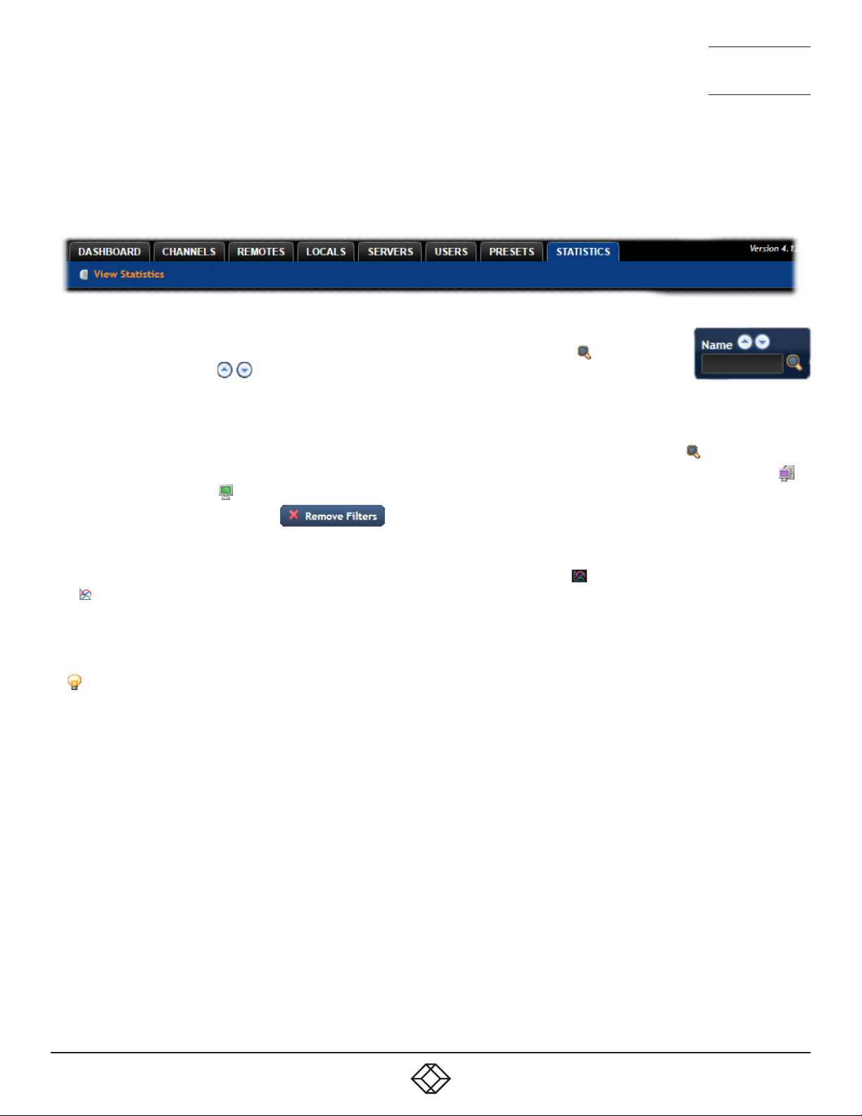
NEED HELP?
LEAVE T HE TEC H TO US
LIVE 24/7
TECHNICAL
SUPPORT
1.877.877.2269
THE STATISTICS TAB
The Statistics tab provides an opportunity to view a range of real-time data measurements related to any links within the iPATH
network. This is particularly useful for optimization and troubleshooting purposes.
Click the STATISTICS tab to view the page.
Search lters
The key fields (Name, Description and Location) all provide a search filter to locate particular items within
long lists. Enter a full or partial search string into the appropriate filter box and then click to start the
search. Optionally use the buttons to invert the order of the listing.
The page will reload with the same pagination/sort order, but with the added search filter. It’s possible to
filter by several columns at once (e.g. search for all entries with “B” in the Name and “Server” in the Location). Search terms are
case-insensitive. You can re-sort and paginate on filtered results without losing the filters.
To remove a filter, click the red cross next to the relevant filter, (you can also empty the search box and click again).
Where many devices are listed, you can also choose to filter by locals or remotes. At the top of the Type column, click either: to
display only locals or click to display only remotes.
To remove all applied filters, click the button.
To view statistics
1 To the right of the unit for which you wish to view statistics, click the dark graph icon ( ) so that it gains a white background (
).
2 Click on the device name to display the available statistics.
A dynamic graph will be displayed showing the chosen data series for the selected Agility units.
Note: When statistics are enabled on a remote, you can also monitor packet loss information, if email or SNMP is enabled.
Identify unit: Causes the LED lights to flash on the front of the selected unit. An alert will be shown if the unit cannot be
contacted (e.g. if it is offline).
66
1. 8 7 7. 87 7. 226 9 BLACKBOX.COM
Page 67
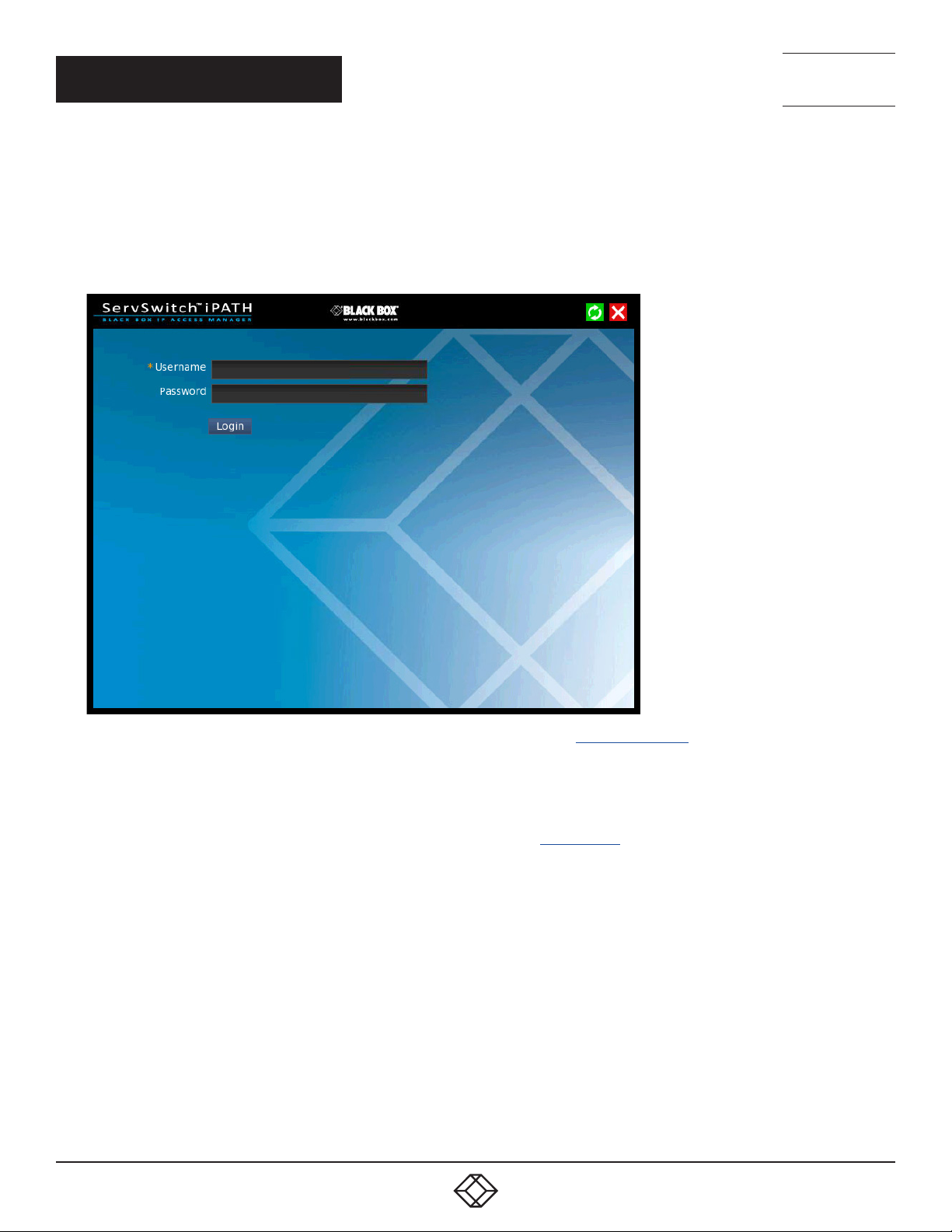
NEED HELP?
LEAVE T HE TEC H TO US
LIVE 24/7
CHAPTER 5: OPERATION
TECHNICAL
SUPPORT
1.877.877.2269
For non-admin users, the On-Screen Display provides a clear way to choose and access multiple channels.
LOGGING IN
1 On the keyboard connected to your Agility remote, press the hotkey combination Ctrl-Alt-C to display the On-Screen Display or
OSD (this hotkey combination can be altered on the Dashboard > Settings > Remotes page).
You will either see the list of channels for which you have permission or be presented with the following login:
2 Enter your Username and Password and click the Login button to display the Local OSD screen.
Once logged in, you will remain logged in until either you click the Logout link in the top right of the OSD; or there is no activity
for two days or until the Agility unit is rebooted.
Hotkey shortcuts
The following standard shortcuts are available for use with the Local OSD (and Remote OSD). These default shortcuts can be altered
within the Dashboard > Settings > Remotes page.
Left Ctrl + Left Alt + C: Launch the OSD
Left Ctrl + Left Alt + X: Disconnect the current remote
Left Ctrl + Left Alt + 3: Connect to the channel/preset saved in shortcut slot 3
Left Ctrl + Left Alt + A: Re-connect to the last channel
Left Ctrl + Left Alt + L: Switch between a locally linked TX and your regular channel
Left Ctrl + Left Alt + V: Change the current connection to the video-only mode
Left Ctrl + Left Alt + S: Change the current connection to the shared mode
Left Ctrl + Left Alt + E: Change the current connection to the exclusive mode
Left Ctrl + Left Alt + P: Change the current connection to the private mode
1. 8 7 7. 87 7. 226 9 BLACKBOX.COM
67
Page 68

NEED HELP?
LEAVE T HE TEC H TO US
LIVE 24/7
TECHNICAL
SUPPORT
1.877.877.2269
Creating/using favorites and shortcuts
When the OSD contains many possible channels and presets, it can be useful to mark the most commonly visited ones as
favorites. For those channels that you’d like to access by keyboard shortcut, there are also ten assignable hotkeys.
To create a new favorite
1 Click the icon next to the required channel or preset.
2 Click the button at the top of the page.
To display favorites
The star shown at the top of the channel list has three appearances to represent the three display modes. Click the star to change
the mode:
Currently showing all channels/presets.
Currently showing only favorites.
Currently showing only numbered shortcuts.
To create a new hotkey shortcut
1 Click the icon next to the required channel or preset. The screen will list the ten hotkey slots, with any available slots listed
as EMPTY. Click the number prefix (from 1 to 0) of an available slot.
Note: To remove a previous channel from a slot, click the icon on the right side of the slot.
2 You will now be asked to choose which mode should be used to access the channel when using this shortcut. Select Video-
Only, Shared, Exclusive or Private, as appropriate.
3 Click the button at the top of the page. As mentioned above, you will now be able to access the chosen channel by
using the hotkeys (Left Ctrl + Left Alt, as standard) plus the number that you assigned to it.
68
1. 8 7 7. 87 7. 226 9 BLACKBOX.COM
Page 69
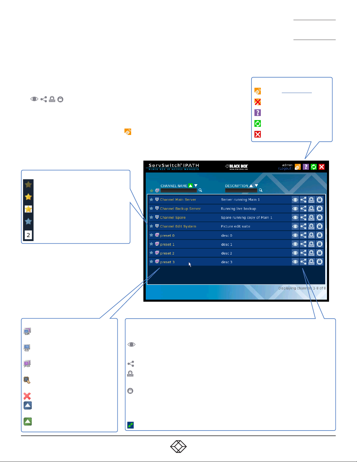
THE LOCAL OSD SCREEN
Once logged in, the list of channels for which you have permission are shown
in the Local OSD (blue bars) screen.
• To choose a channel/preset, click on one of the blue connection icons
(
(see the Connection buttons box below right).
• Where many channels/presets are listed, use the Channel Name and
Description search boxes and list arrows to filter the choices.
• To use the Remote OSD feature, click the icon in the top right corner.
) shown to the right of the required channel/preset name
FAVORITES ICONS
NEED HELP?
LEAVE T HE TEC H TO US
LIVE 24/7
TECHNICAL
SUPPORT
1.877.877.2269
TOP CORNER ICONS
Enter ‘Remote OSD’ mode
Exit ‘Remote OSD’ mode
Display the help pages
Refresh the current page
Close the OSD
Currently showing all channels/presets
Currently showing only favorites
Currently showing only numbered shortcuts
Click to add this channel as a favorite
This channel is a numbered shortcut
SORTING ICONS
Currently showing channels and
presets. Click to change
Currently showing only channels.
Click to change
Currently showing only presets.
Click to change
Filter this column using the speci-
fied term
Remove the search filter
Click to sort the list in ascending
order via this column
The list is sorted in ascending
order via this column
CONNECTION BUTTONS
There are four connection modes:
Video-Only: Allows users only to view the video output, the USB channel is
denied.
Shared: Allows users to control a system in conjunction with other users.
Exclusive: Grants exclusive control to one user while all others can
simultaneously view and hear, but not control, the output.
Private: Allows a user to gain private access to a system, while locking out
all others.
Connection buttons shown in blue are ready to select. Icons in green have been
selected by another user and those shown in gray are not available.
End this connection
1. 8 7 7. 87 7. 226 9 BLACKBOX.COM
69
Page 70
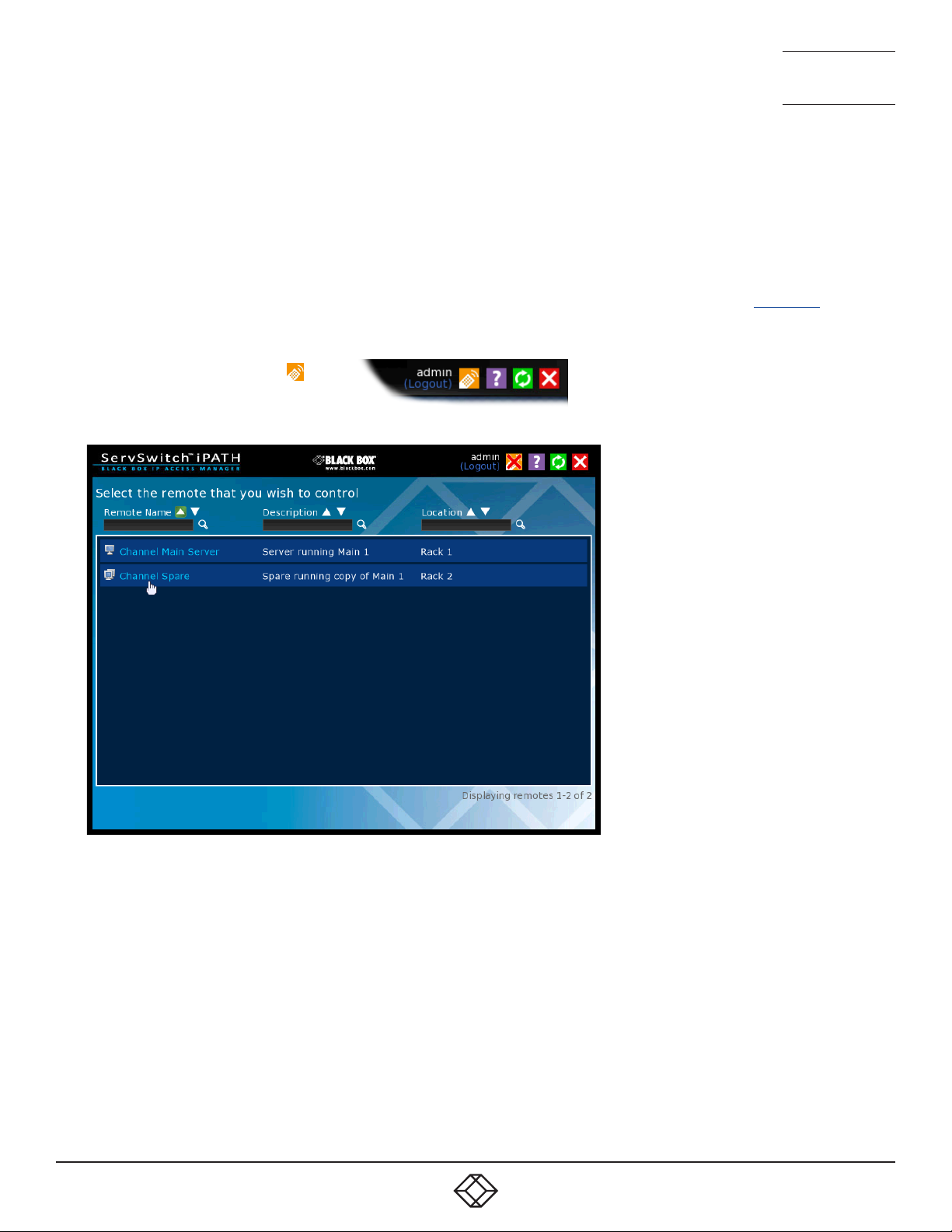
NEED HELP?
LEAVE T HE TEC H TO US
LIVE 24/7
TECHNICAL
SUPPORT
1.877.877.2269
Using the Remote OSD feature
The Remote OSD feature allows authorized users to access and take control of Agility remotes other than the one to which they
are connected. Once linked in, users can then determine which channels the remote remotes should link with.
Remote OSD requires that a user must have been given specific authorization to access one or more remote remotes.
To access the Remote OSD
1 On the keyboard connected to your Agility remote, press the hotkey combination Ctrl-Alt-C to display the Local OSD login
screen.
2 If required, enter your Username and Password and click the Login button.
3 In the top right corner, click the icon.
4 The screen will list all of the remotes to which you have access rights. Click on the required remote from the list:
70
1. 8 7 7. 87 7. 226 9 BLACKBOX.COM
Page 71
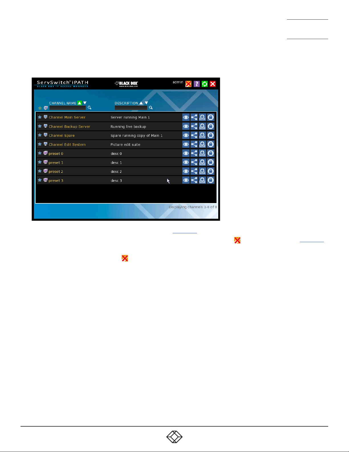
NEED HELP?
LEAVE T HE TEC H TO US
LIVE 24/7
TECHNICAL
SUPPORT
1.877.877.2269
5 The Remote OSD for the chosen Agility remote will be displayed. Remote OSDs always have black horizontal bars in the background
to differentiate them from the standard local OSD:
6 The behavior of the controls is generally the same as for the Local OSD screen with the following exceptions:
• To avoid confusion, you cannot login or logout while in Remote OSD mode. Click the icon to first return to the Local OSD.
• Hotkeys will only affect the current remote to which you are connected, not the remotely-controlled remote.
7 To exit from the Remote OSD, click the icon in the top right corner.
1. 8 7 7. 87 7. 226 9 BLACKBOX.COM
71
Page 72

CHAPTER 6: FURTHER INFORMATION
This chapter contains a variety of information, including the following:
• Appendix A - Tips for success when networking Agility units
• Appendix B - Troubleshooting
• Appendix C - Redundant servers: Setting up and swapping out
• Appendix D - Upgrade Licence
• Appendix E - Glossary
• Appendix F - iPATH API
• Appendix G - DHCP server requirements for Agility support
• Appendix H - Using DHCP Option 125
• Safety information
NEED HELP?
LEAVE T HE TEC H TO US
LIVE 24/7
TECHNICAL
SUPPORT
1.877.877.2269
72
1. 8 7 7. 87 7. 226 9 BLACKBOX.COM
Page 73

NEED HELP?
LEAVE T HE TEC H TO US
LIVE 24/7
TECHNICAL
SUPPORT
1.877.877.2269
APPENDIX A. TIPS FOR SUCCESS WHEN NETWORKING AGILITY UNITS
Agility units use multiple strategies to minimise the amount of data that they send across networks. However, data overheads can be
quite high, particularly when very high resolution video is being transferred, so it is important to take steps to maximise network efficiency and help minimise data output. The tips given in this section have been proven to produce very beneficial results.
SUMMARY OF STEPS
• Choose the right kind of switch.
• Create an efficient network layout.
• Configure the switches and devices correctly.
CHOOSING THE RIGHT SWITCH
Layer 2 switches are what bind all of the hosts together in the subnet. However, they are all not created equally, so choose carefully.
In particular look for the following:
• Gigabit (1000Mbps) or faster Ethernet ports,
• Support for IGMP v2 (or v3) snooping,
• Support for Jumbo frames up to 9216-byte size,
• High bandwidth connections between switches, preferably Fiber Channel.
• Look for switches that perform their most onerous tasks (e.g. IGMP snooping) using multiple dedicated processors (ASICS).
• Ensure the maximum number of concurrent ‘snoopable groups’ the switch can handle meets or exceeds the number of Agility
locals that will be used to create multicast groups.
• Check the throughput of the switch: Full duplex, 1Gbps up- and down- stream speeds per port.
• Use the same switch make and model throughout a single subnet.
• You also need a Layer 3 switch. Ensure that it can operate efficiently as an IGMP Querier.
LAYER 2 (AND LAYER 3) SWITCHES KNOWN TO WORK
• Cisco 2960
• Cisco 3750
• Cisco 4500
• Cisco 6500
• Extreme Networks X480
• HP Procurve 2810
• HP Procurve 2910
• H3C 5120
• HuaWei Quidway s5328c-E1 (Layer 3)
1. 8 7 7. 87 7. 226 9 BLACKBOX.COM
73
Page 74
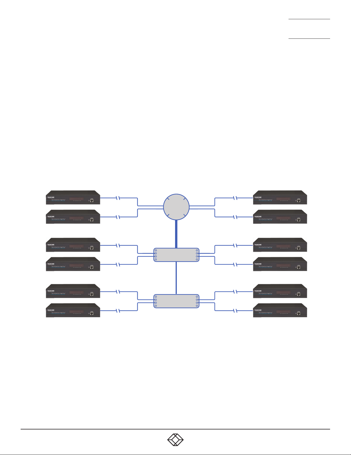
NEED HELP?
LEAVE T HE TEC H TO US
LIVE 24/7
TECHNICAL
SUPPORT
1.877.877.2269
CREATING AN EFFICIENT NETWORK LAYOUT
Network layout is vital. The use of IGMP snooping also introduces certain constraints, so take heed:
• Keep it flat. Use a basic line-cascade structure rather than a pyramid or tree arrangement (see note below).
• Keep the distances between the switches as short as possible.
• Ensure sufficient bandwidth between switches to eliminate bottlenecks.
• Where the iPATH Agility Controller manager is used to administer multiple Agility transceivers, ensure the iPATH Agility Controller
manager and all Agility units reside in the same subnet.
• Do not use VGA to DVI converters, instead replace VGA video cards in older systems with suitable DVI replacements. Converters
cause Agility local units to massively increase data output.
• Wherever possible, create a private network.
THE RECOMMENDED LAYOUT
The layout shown in Figure A-1 below has been found to provide the most efficient network layout for rapid throughput when using
IGMP snooping:
Layer 3
Switch
(Querier)
20GB link
Layer 2 Switch
10GB link
Layer 2 Switch
1GB links
Note: From firmware version 3.0, tree and hierarchical structures of network switches are also supported. The Local now joins its own
multicast group so there is always a route from the querier to the local which was previously missing in firmware versions 2.9 and
below.
• Use no more than two cascade levels.
• Ensure high bandwidth between the two L2 switches and very high bandwidth between the top L2 and the L3. Typically 10GB and
20GB, respectively for 48 port L2 switches.
74
1. 8 7 7. 87 7. 226 9 BLACKBOX.COM
Page 75

NEED HELP?
LEAVE T HE TEC H TO US
LIVE 24/7
TECHNICAL
SUPPORT
1.877.877.2269
CONFIGURING THE SWITCHES AND DEVICES
The layout is vital but so too is the configuration:
• Enable IGMP Snooping on all L2 switches.
• Ensure that IGMP Fast-Leave is enabled on all switches with Agility units connected directly to them.
• Enable the L3 switch as an IGMP Querier.
• Enable Spanning Tree Protocol (STP) on all switches and importantly also enable portfast (only) on all switch ports that have
Agility units connected.
• If any hosts will use any video resolutions using 2048 horizontal pixels (e.g. 2048 x 1152), ensure that Jumbo Frames are enabled
on all switches.
• Choose an appropriate forwarding mode on all switches. Use Cut-through if available, otherwise Store and forward.
• Optimize the settings on the Agility locals:
• If moving video images are being shown frequently, then leave Frame Skipping at a low percentage and instead reduce the
Peak bandwidth limiter.
• Where screens are quite static, try increasing the Background Refresh interval and/or increasing the Frame skipping percentage setting.
Make changes to the Agility locals one at a time, in small steps, and view typical video images so that you can attribute positive
or negative results to the appropriate control.
• Ensure that all Agility units are fully updated to the latest firmware version (at least v3.3).
1. 8 7 7. 87 7. 226 9 BLACKBOX.COM
75
Page 76

NEED HELP?
LEAVE T HE TEC H TO US
LIVE 24/7
TECHNICAL
SUPPORT
1.877.877.2269
APPENDIX B. TROUBLESHOOTING
PROBLEM: THE VIDEO IMAGE OF THE AGILITY REMOTE SHOWS HORIZONTAL LINES ACROSS THE
SCREEN.
This issue is known as Blinding because the resulting video image looks as though you’re viewing it through a venetian blind.
When video is transmitted by Agility units, the various lines of each screen are divided up and transmitted as separate data packets.
If the reception of those packets is disturbed, then blinding is caused. The lines are displayed in place of the missing video data
packets.
There are several possible causes for the loss of data packets:
• Incorrect switch configuration. The problem could be caused by multicast flooding, which causes unnecessary network traffic.
This is what IGMP snooping is designed to combat, however, there can be numerous causes of the flooding.
• Speed/memory bandwidth issues within one or more switches. The speed and capabilities of different switch models varies
greatly. If a switch cannot maintain pace with the quantity of data being sent through it, then it will inevitably start dropping packets.
• One or more Agility units may be outputting Jumbo frames due to the video resolution (2048 horizontal pixels) being used. If
jumbo frames are output by a Agility unit, but the network switches have not been configured to use jumbo frames, the switches
will attempt to break the large packets down into standard packets. This process introduces a certain latency and could be a
cause for dropped packets.
• One or more Agility units may be using an old firmware version. Firmware versions prior to v2.1 exhibited an issue with the timing
of IGMP join and leave commands that caused multicast flooding in certain configurations.
REMEDIES:
• Ensure that IGMP snooping is enabled on all switches within the subnet.
• Where each Agility unit is connected as the sole device on a port connection to a switch, enable IGMP Fast-Leave (aka Immediate
Leave) to reduce unnecessary processing on each switch.
• Check the video resolution(s) being fed into the Agility locals. If resolutions using 2048 horizontal pixels are unavoidable then
ensure that Jumbo frames are enabled on all switches.
• Check the forwarding mode on the switches. If Store and forward is being used, try selecting Cut-through as this mode causes
reduced latency on lesser switch designs.
• Ensure that one device within the subnet is correctly configured as an IGMP Querier, usually a layer 3 switch or multicast router.
• Ensure that the firmware in every Agility unit is version 3.3 or greater.
• Try adjusting the local settings on each Agility to make the output data stream as efficient as possible.
76
1. 8 7 7. 87 7. 226 9 BLACKBOX.COM
Page 77

NEED HELP?
LEAVE T HE TEC H TO US
LIVE 24/7
TECHNICAL
SUPPORT
1.877.877.2269
PROBLEM: THE AUDIO OUTPUT OF THE AGILITY REMOTE SOUNDS LIKE A SCRATCHED RECORD.
This issue is called Audio crackle and is a symptom of the same problem that produces blinding (see previous page). The issue is
related to missing data packets.
REMEDIES:
As per blinding discussed above.
PROBLEM: THE MOUSE POINTER OF THE AGILITY REMOTE IS SLOW OR SLUGGISH WHEN MOVED
ACROSS THE SCREEN.
This issue is often related to either using dithering on the video output of one or more transmitting computers or using VGA-to-DVI
video converters.
Dithering is used to improve the perceived quality and color depth of images by diffusing or altering the color of pixels between video
frames. This practice is commonly used on Apple® Mac computers using ATI or Nvidia graphics cards. VGA-to-DVI converters
unwittingly produce a similar issue by creating high levels of pixel background noise.
Agility units attempt to considerably reduce network trafc by transmitting only the pixels that change between successive video
frames. When dithering is enabled and/or VGA-to-DVI converters are used, this can have the effect of changing almost every pixel
between each frame, thus forcing the Agility local to send the whole of every frame: resulting in greatly increased network trafc
and what’s perceived as sluggish performance.
REMEDIES:
• Linux PCs
Check the video settings on the PC. If the Dither video box option is enabled, disable it.
• Apple Mac with Nvidia graphics
Use the Black Box utility for Mac’s – Contact technical support.
• Apple Mac with ATI graphics
Use the Agility Dual series unit with Magic Eye dither removal feature.
• Windows PCs
If you suspect these issues with PC’s, contact technical support for assistance.
• Replace old VGA adapters on host computers with DVI video cards.
1. 8 7 7. 87 7. 226 9 BLACKBOX.COM
77
Page 78

NEED HELP?
LEAVE T HE TEC H TO US
LIVE 24/7
TECHNICAL
SUPPORT
1.877.877.2269
PROBLEM: IPATH AGILITY CONTROLLER CANNOT LOCATE WORKING AGILITY UNITS.
There are a few possible causes:
• The Agility units must be reset back to their zero config IP addresses for iPATH Agility Controller discovery. If you have a working
network of Agility unit’s without iPATH Agility Controller and then add iPATH Agility Controller to the network, the iPath manager
will not discover the Agility units until they are reset to the zero config IP addresses.
• This could be caused by Layer 2 Cisco switches that have Spanning Tree Protocol (STP) enabled but do not also have portfast
enabled on the ports to which Agility units are connected. Without portfast enabled, Agility units will all be assigned the same
zero config IP address at reboot and iPATH Agility Controller will only acquire them one at a time on a random basis.
You can easily tell whether portfast is enabled on a switch that is running STP: When you plug the link cable from a working
Agility unit into the switch port, check how long it takes for the port indicator to change from orange to green. If it takes roughly
one second, portfast is on; if it takes roughly thirty seconds then portfast is disabled.
REMEDIES:
• Ensure that the Agility units and the iPATH Agility Controller manager are located within the same subnet. iPATH Agility Controller
cannot cross subnet boundaries.
• Manually reset the Agility units to their zero config IP addresses.
• Enable portfast on all switch ports that have Agility units attached to them or try temporarily disabling STP on the switches while
iPATH Agility Controller is attempting to locate Agility units.
78
1. 8 7 7. 87 7. 226 9 BLACKBOX.COM
Page 79

NEED HELP?
LEAVE T HE TEC H TO US
LIVE 24/7
TECHNICAL
SUPPORT
1.877.877.2269
APPENDIX C. REDUNDANT SERVERS: SETTING UP AND SWAPPING OUT
This appendix contains two main sections related to the creation and repair of iPATH Agility Controller installations that employ
redundancy.
• Setting up iPATH Agility Controller redundancy - below
• Swapping out an iPATH Agility Controller - on next page
SETTING UP IPATH AGILITY CONTROLLER REDUNDANCY
This section details the steps required to successfully configure two iPATH units as primary and secondary servers.
1 Set the Rôle entry to Primary on the primary server.
2 Configure its Ethernet port 1 Address.
3 Ensure that password requirements is set to NO.
4 Add the new secondary iPATH Agility Controller to the network. The secondary server must have the same license as the
primary. It is not possible to have two servers with different licenses in a cluster. This unit must have its factory default
settings in place. The new server will appear within the main Servers tab and be identified as being Unconfigured.
5 Wait five minutes for automatic server replication to take place and the backup database to be transferred from the primary
unit. After this period, the new secondary server will be added to the list on the main Servers tab. Its Rôle will be shown as
backup and its Status as standby.
Note: If the transfer of the backup database is interrupted and only a partial database is transferred, then the problem will be
reported within the management server page. If this occurs, it will not be possible to log in to the backup database and the
firmware version of the backup will be reported as V. After five minutes, you should be given the options of Reboot and Factory
Reset. Choose the Factory Reset option in order to clear this issue.
6 You can now configure the secondary server in either of two ways:
• Click the icon to configure the server remotely from the primary server.
• Click the icon to open a restricted page in order to configure the server directly from its own IP address. If you use this
option, the configuration options are limited to: view the logs; update/reset the iPATH Agility Controller and configure this server.
OPERATION OF REDUNDANCY
If the Primary server fails for any reason (for example, loss of power or a network issue) then the secondary server will failover. This
will happen automatically without any user intervention, however it is not instantaneous. The failover time required is the value
entered in the primary timeout plus 30 seconds for the process to happen. The Agility extenders will start communication with the
second IP address that is stored in their configuration and the redundant server will take control of the Agility units. When the redundant server is acting as the primary it is not possible to add any new devices or change the configuration. If this is required then the
backup server can be promoted to be the primary.
When the primary server comes back online then it will resume its role as the primary. If however the backup server has been promoted to primary, when the primary server comes back its role will need to be factory reset back to the backup. It is not possible to
have two primary servers on the same network.
Both the primary and the backup server periodically synchronize their databases to ensure that they are identical. If for any reason
the backup server is powered down then any changes to the system configuration will not be maintained by the backup server.
1. 8 7 7. 87 7. 226 9 BLACKBOX.COM
79
Page 80

NEED HELP?
LEAVE T HE TEC H TO US
LIVE 24/7
TECHNICAL
SUPPORT
1.877.877.2269
SWAPPING OUT AN IPATH AGILITY CONTROLLER
Once Agility devices have been configured to run with an iPATH Agility Controller, their default IP addresses are automatically
changed as part of the installation process. In this state the Agility devices become undetectable to any new iPATH Agility Controller
that does not have access to the database of devices. Therefore, if an existing iPATH Agility Controller needs to be replaced within an
installation, follow one of the basic procedures given here to smooth the transition.
The correct procedure to use depends on whether you are using a solo iPATH Agility Controller (firmware versions below 3.0 can
only be used as solo servers) or a pair of iPATH Agility Controllers in a primary/backup redundancy arrangement:
FOR SOLO IPATH AGILITY CONTROLLERS
1 Before connecting the new iPATH Agility Controller to the main network, connect the new iPATH Agility Controller to a network
switch that is isolated from the main network.
2 Use a computer connected to the same switch to login to the new iPATH Agility Controller management suite.
3 Set the Rôle entry to Solo.
4 Set the IP address of the new iPATH Agility Controller to match that of the original unit.
5 Restore a backup file of the original iPATH Agility Controller database to the new device.
6 Remove the original iPATH Agility Controller from the network. Connect the new iPATH Agility Controller in its place and power up.
7 All the devices will appear as offline. Using a paperclip, perform a factory reset on all the Agility endpoints so as they acquire
the new certicate and keys. All Agility units require a minimum of rmware version 3.3.
FOR DUAL IPATH INSTALLATIONS USING REDUNDANCY
The correct procedure depends on which iPATH Agility Controller has failed:
Primary server failure
1 Promote the backup server to be the primary server.
2 Delete the failed server from the database.
3 Replace the faulty primary iPATH Agility Controller with a replacement unit that has the same license version and has its default
factory settings in place.
4 The replacement server will begin communicating with the primary server and download the database so that it can operate as
the backup server. This process may take ten minutes.
5 Reboot the Agility endpoints at the earliest opportunity.
Backup server failure
1 Delete the failed server from the database.
2 Replace the failed backup server with a new unit that has the same license version and has its default factory settings in place.
3 The replacement server will begin communicating with the primary server and download the database so that it can operate as
the backup server. This process may take ten minutes.
4 Reboot the Agility endpoints at the earliest opportunity.
Warning: If step 4, rebooting the Agility endpoints, does not happen then the Agility endpoints will be offline if a failover occurs
and will need to be factory reset with a paperclip.
80
1. 8 7 7. 87 7. 226 9 BLACKBOX.COM
Page 81

NEED HELP?
LEAVE T HE TEC H TO US
LIVE 24/7
TECHNICAL
SUPPORT
1.877.877.2269
STARTING FROM SCRATCH
If none of the above procedures are used, then the following will be necessary. This will require a certain amount of effort because
each Agility unit must be visited and reset, plus the iPATH database will need to be fully reconfigured.
1 Place a new iPATH Agility Controller into the network and then perform a factory reset on every Agility device. This will force the
Agility units back to their default states whereupon they will announce themselves to the new iPATH Agility Controller.
2 Use a computer connected to the same network to login to the new iPATH Agility Controller management suite and begin to rec-
reate the database of devices and users.
1. 8 7 7. 87 7. 226 9 BLACKBOX.COM
81
Page 82
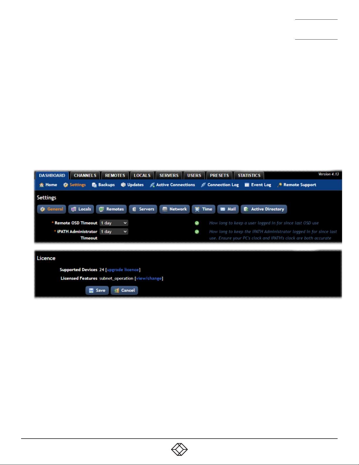
NEED HELP?
LEAVE T HE TEC H TO US
LIVE 24/7
TECHNICAL
SUPPORT
1.877.877.2269
APPENDIX D. UPGRADE LICENCE
iPATH Agility Controllers are licenced according to the number of devices that can be managed. As your installation grows you can
purchase an updated iPATH licence at any time using the following procedure. Four licences are available, ranging from a maximum
of 24 managed devices up to a maximum of 288:
• iPATH-24-48UPG - increases the maximum number of managed devices from 24 to 48.
• iPATH-48-96UPG - increases the maximum number of managed devices from 48 to 96.
• iPATH-96-192UPG - increases the maximum number of managed devices from 96 to 192.
• iPATH-192-288UPG - increases the maximum number of managed devices from 192 to 288.
TO UPGRADE YOUR IPATH LICENCE
1 Visit the Dashboard > Settings > General page of the iPATH unit to be upgraded. At the bottom of the page, click the ‘upgrade
licence’ link:
The subsequent file dialog will show a Product Code that is unique to your iPATH Agility Controller.
2 Contact your supplier and quote all of the following:
• The unique product code,
• The serial number of the iPATH Agility Controller (marked on a label on the base of the unit),
• The current number of supported devices, and
• The number of devices to which you wish to upgrade.
3 The supplier will provide a licence key, which is unique to unit to the unit to be upgraded. Enter the new licence key into the blank
entry in the page shown above.
Note: It is important that you only enter the licence key into the specific iPATH unit.
If the upgrade is successful, the new number of supported devices will be shown in the Dashboard > Settings > General page.
82
1. 8 7 7. 87 7. 226 9 BLACKBOX.COM
Page 83

NEED HELP?
LEAVE T HE TEC H TO US
LIVE 24/7
TECHNICAL
SUPPORT
1.877.877.2269
APPENDIX E. GLOSSARY
INTERNET GROUP MANAGEMENT PROTOCOL
Where a Agility local is required to stream video to two or more remotes, multicasting is the method used.
Multicasting involves the delivery of identical data to multiple remotes simultaneously without the need to maintain individual
links. When multicast data packets enter a subnet, the natural reaction of the switches that bind all the hosts together within the
subnet, is to spread the multicast data to all of their ports. This is referred to as Multicast flooding and means that the hosts (or at
least their network interfaces) are required to process plenty of data that they didn’t request. IGMP offers a partial solution.
The Internet Group Management Protocol (IGMP) is designed to prevent multicast flooding by allowing Layer 3 switches to check
whether host computers within their care are interested in receiving particular multicast transmissions. They can then direct multicast data only to those points that require it and can shut off a multicast stream if the subnet has no recipients.
There are currently three IGMP versions: 1, 2 and 3, with each version building upon the capabilities of the previous one:
• IGMPv1 allows host computers to opt into a multicast transmission using a Join Group message, it is then incumbent on the router to discover when they no longer wish to receive; this is achieved by polling them (see IGMP Querier below) until they no longer
respond.
• IGMPv2 includes the means for hosts to opt out as well as in, using a Leave Group message.
• IGMPv3 encompasses the abilities of versions 1 and 2 but also adds the ability for hosts to specify particular sources of multicast
data.
Agility units make use of IGMPv2 when performing multicasts to ensure that no unnecessary congestion is caused.
IGMP SNOOPING
The IGMP messages are effective but only operate at layer 2 - intended for routers to determine whether multicast data should enter
a subnet. A relatively recent development has taken place within the switches that glue together all of the hosts within each subnet:
IGMP Snooping. IGMP snooping means these layer 2 devices now have the ability to take a peek at the IGMP messages. As a result,
the switches can then determine exactly which of their own hosts have requested to receive a multicast – and only pass on multicast data to those hosts.
IGMP QUERIER
When IGMP is used, each subnet requires one Layer 3 switch to act as a Querier. In this lead role, the switch periodically sends out
IGMP Query messages and in response all hosts report which multicast streams they wish to receive. The Querier device and all
snooping Layer 2 switches, then update their lists accordingly (the lists are also updated when Join Group and Leave Group
(IGMPv2) messages are received).
IGMP FAST-LEAVE (AKA IMMEDIATE LEAVE)
When a device/host no longer wishes to receive a multicast transmission, it can issue an IGMP Leave Group message as mentioned
above. This causes the switch to issue an IGMP Group-Specific Query message on the port (that the Leave Group was received on)
to check no other remotes exist on that connection that wish to remain a part of the multicast. This process has a cost in terms of
switch processor activity and time.
Where Agility units are connected directly to the switch (with no other devices on the same port) then enabling IGMP Fast-Leave
mode means that switches can immediately remove remotes without going through a full checking procedure. Where multiple units
are regularly joining and leaving multicasts, this can speed up performance considerably.
1. 8 7 7. 87 7. 226 9 BLACKBOX.COM
83
Page 84

NEED HELP?
LEAVE T HE TEC H TO US
LIVE 24/7
TECHNICAL
SUPPORT
1.877.877.2269
JUMBO FRAMES (JUMBO PACKETS)
Since its commercial introduction in 1980, the Ethernet standard has been successfully extended and adapted to keep pace with the
ever improving capabilities of computer systems. The achievable data rates, for instance, have risen in ten-fold leaps from the original 10Mbit/s to a current maximum of 100Gbit/s.
While data speeds have increased massively, the standard defining the number of bytes (known as the Payload) placed into each
data packet has remained resolutely stuck at its original level of 1500 bytes. This standard was set during the original speed era
(10Mbits/s) and offered the best compromise at that speed between the time taken to process each packet and the time required to
resend faulty packets due to transmission errors.
But now networks are much faster and files/data streams are much larger; so time for a change? Unfortunately, a wholesale change
to the packet size is not straightforward as it is a fundamental standard and changing it would mean a loss of backward compatibility with older systems.
Larger payload options have been around for a while, however, they have often been vendor specific and at present they remain outside the official standard. There is, however, increased consensus on an optional ‘Jumbo’ payload size of 9000 bytes and this is fully
supported by the Agility units.
Jumbo frames (or Jumbo packets) offer advantages for Agility units when transmitting certain high resolution video signals across a
network. This is because the increased data in each packet reduces the number of packets that need to be transferred and dealt with
- thus reducing latency times.
The main problem is that for jumbo frames to be possible on a network, all of the devices on the network must support them.
SPANNING TREE PROTOCOL (STP)
In order to build a robust network, it is necessary to include certain levels of redundancy within the interconnections between
switches. This will help to ensure that a failure of one link does not lead to a complete failure of the whole network.
The danger of multiple links is that data packets, especially multicast packets, become involved in continual loops as neighbouring
switches use the duplicated links to send and resend them to each other.
To prevent such bridging loops from occurring, the Spanning Tree Protocol (STP), operating at layer 2, is used within each switch.
STP encourages all switches to communicate and learn about each other. It prevents bridging loops by blocking newly discovered
links until it can discover the nature of the link: is it a new host or a new switch?
The problem with this is that the discovery process can take up to 50 seconds before the block is lifted, causing problematic timeouts.
The answer to this issue is to enable the portfast variable for all host links on a switch. This will cause any new connection to go
immediately into forwarding mode. However, take particular care not to enable portfast on any switch to switch connections as this
will result in bridging loops.
84
1. 8 7 7. 87 7. 226 9 BLACKBOX.COM
Page 85

NEED HELP?
LEAVE T HE TEC H TO US
LIVE 24/7
TECHNICAL
SUPPORT
1.877.877.2269
FORWARDING MODES
In essence, the job of a layer 2 switch is to transfer as fast as possible, data packets arriving at one port out to another port as determined by the destination address. This is known as data forwarding and most switches offer a choice of methods to achieve this.
Choosing the most appropriate forwarding method can often have a sizeable impact on the overall speed of switching:
• Store and forward is the original method and requires the switch to save each entire data packet to buffer memory, run an error
check and then forward if no error is found (or otherwise discard it).
• Cut-through was developed to address the latency issues suffered by some store and forward switches. The switch begins inter-
preting each data packet as it arrives. Once the initial addressing information has been read, the switch immediately begins forwarding the data packet while the remainder is still arriving. Once all of the packet has been received, an error check is performed
and, if necessary, the packet is tagged as being in error. This checking ‘on-the-fly’ means that cut-through switches cannot discard faulty packets themselves. However, on receipt of the marked packet, a host will carry out the discard process.
• Fragment-free is a hybrid of the above two methods. It waits until the first 64 bits have been received before beginning to forward
each data packet. This way the switch is more likely to locate and discard faulty packets that are fragmented due to collisions
with other data packets.
• Adaptive switches automatically choose between the above methods. Usually they start out as a cut-through switches and
change to store and forward or fragment-free methods if large number of errors or collisions are detected.
So which one to choose? The Cut-through method has the least latency so is usually the best to use with Agility units. However, if
the network components and/or cabling generate a lot of errors, the Store and forward method should probably be used. On higher
end store and forward switches, latency is rarely an issue.
1. 8 7 7. 87 7. 226 9 BLACKBOX.COM
85
Page 86
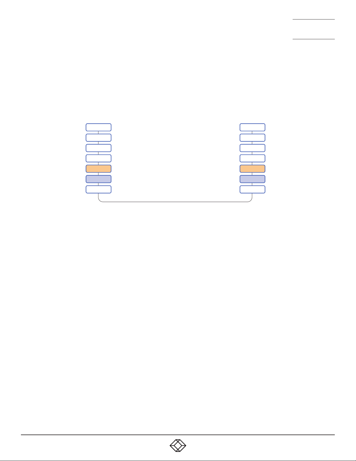
NEED HELP?
7L
6L
5L
4L
3L
2L
1L
Network connection
LEAVE T HE TEC H TO US
LIVE 24/7
TECHNICAL
SUPPORT
1.877.877.2269
LAYER 2 AND LAYER 3: THE OSI MODEL
When discussing network switches, the terms Layer 2 and Layer 3 are very often used. These refer to parts of the Open System
Interconnection (OSI) model, a standardized way to categorize the necessary functions of any standard network.
There are seven layers in the OSI model (see Figure C-1) and these define the steps needed to get the data created by you (imagine
that you are Layer 8) reliably down onto the transmission medium (the cable, optical fiber, radio wave, etc.) that carries the data to
another user; to complete the picture, consider the transmission medium is Layer 0. In general, think of the functions carried out by
the layers at the top as being complex, becoming less complex as you go lower down.
LAYER
LAYER
LAYER
LAYER
LAYER
LAYER
LAYER
Application
Presentation
Session
Transport
Network
Data Link
Physical
AYER 7
AYER 6
AYER 5
AYER 4
AYER 3
AYER 2
AYER 1
A representation of the seven layers defined by the OSI Model
As your data travel down from you towards the transmission medium (the cable), they are successively encapsulated at each layer
within a new wrapper (along with a few instructions), ready for transport. Once transmission has been made to the intended destination, the reverse occurs: Each wrapper is stripped away and the instructions examined until finally only the original data are left.
So why are Layer 2 and Layer 3 of particular importance when discussing Agility? Because the successful transmission of data
relies upon fast and reliable passage through network switches – and most of these operate at either Layer 2 or Layer 3.
The job of any network switch is to receive each incoming network packet, strip away only the first few wrappers to discover the
intended destination then rewrap the packet and send it in the correct direction.
In simplified terms, the wrapper that is added at Layer 2 (by the sending system) includes the physical address of the intended recipient system, i.e. the unique MAC address (for example, 09:f8:33:d7:66:12) that is assigned to every networking device at manufacture.
Deciphering recipients at this level is more straightforward than at Layer 3, where the address of the recipient is represented by a
logical IP address (e.g. 192.168.0.10) and requires greater knowledge of the surrounding network structure. Due to their more complex circuitry, Layer 3 switches are more expensive than Layer 2 switches of a similar build quality and are used more sparingly within installations.
86
1. 8 7 7. 87 7. 226 9 BLACKBOX.COM
Page 87

NEED HELP?
LEAVE T HE TEC H TO US
LIVE 24/7
TECHNICAL
SUPPORT
1.877.877.2269
APPENDIX F. iPATH API
The iPATH API provides access for external applications to key routines used within the iPATH Agility Controller. This appendix
provides a reference to the available methods.
Note: The API is documented as an HTML file and is found by going to the following address: http://<ip address>/api/
A windows application called the iPATH Controller is available for download, whose purpose is to demo and show you the API
working in action. An example C# API class has been written and published on Github. It is free to download, but comes with no
support or warranty,
Best Practices
Do not login and generate a new token for every API request. When you first connect to the iPATH, login and store a copy of the
token that you are given, and use it for future requests. Each token that you request, creates a stored session within the iPATH
Manager. The duration of the session is defined by the iPATH’s Admin timeout that is set on the web interface under Dashboard ->
Settings -> General. Creating a new token on every request will result in hundreds if not thousands of stored sessions, each taking
a small amount of space on the iPATH’s SSD drive. If a particularly long session duration is set, for example 3 years then this could
easily fill the drive over time since they don’t get deleted until they expire.
Do not keep the HTTP port open. When making a request, simply send the api command, wait for the response and then close the
connection. A typical web browser will fetch the html page and its associated files such as images, javascripts and ccs files and
then close the connection. The iPATH runs a standard Apache web service. There is no guarantee that the HTTP connection that
you initially establish will always remain open.
The API is restful based, this means that you have to periodically request information from the iPATH and compare the previous
and latest responses to see what has changed. Be careful not to continuously send API requests as they consume resources on
the iPATH. Requesting the Devices, Channels, Presets and C-USB information every 5-10 seconds should usually suffice to monitor
changes.
Session tokens are linked to the IP address of the host that connected to the iPATH. If you change the IP address of the host and
use the same token then the API will throw an error telling you that there is a mis-match.
On the iPATH Controller API demo the procedure below has been used when sending API requests. This ensures that you are
working with a valid token, assuming your login credentials are correct. The initial API request does not send a token, however the
procedure takes care of that.
Example Connection Procedure
1 Establish the HTTP connection.
2 Send the API request (with the stored token, if known)
3 Read the response.
• If the response is a Login error then
• Send a login request with the appropriate username and password.
• Read the response.
• If the login request is successful, extract and store the new token.
- Go back to step 2 and resend the original API request with the stored token.
• If the login request fails, then handle appropriately.
• If the response is different error then handle it appropriately.
4 Close the HTTP connection.
5 Process the response.
Repeat above procedure for the next API command.
1. 8 7 7. 87 7. 226 9 BLACKBOX.COM
87
Page 88

NEED HELP?
LEAVE T HE TEC H TO US
LIVE 24/7
TECHNICAL
SUPPORT
1.877.877.2269
Using a Web Browser to test the API
You can use a web browser to issue test API commands to the iPATH Manager, however, when you authenticate and receive a
token, a web session is also created between the browser and iPATH. If you try to use the same web browser to also access the
iPATH’s admin web interface, a different session will be created. This can cause the API token to become invalid on the browser. To
resolve this, it is recommended that you use two different web browsers, for example, Google Chrome for the API and FireFox for the
iPATH’s admin web interface. This will allow two different sessions to operate simultaneously. This only affects web browsers.
API version: 8
Changelog
v8 (iPATH v5.0) - updated get_channels.
v7 (iPATH v4.8) - added reboot_devices.
v6 (iPATH v4.5) - added get_all_c_usb, delete_c_usb, update_c_usb, connect_c_usb, disconnect_c_usb.
v5 (iPATH v4.3) - added update_device; updated get_devices, connect_channel, connect_preset, create_channel, create_preset.
v4 (iPATH v4.1) - added create_channel, delete_channel; updated get_channels.
v3 (iPATH v3.2) - added create_preset, delete_preset.
v2 (iPATH v2.3) - added get_devices, get_channels, connect_channel, disconnect_channel. Updated version compatibility
information.
v1 (iPATH v1.3) - added login, logout, get_presets, connect_preset, disconnect_preset
Methods
login
logout
get_devices
get_channels
get_presets
connect_channel
connect_preset
disconnect_channel
disconnect_preset
create_preset
delete_preset
create_channel
delete_channel
update_device
get_all_c_usb
delete_c_usb
update_c_usb
connect_c_usb
disconnect_c_u sb
reboot_devices
88
1. 8 7 7. 87 7. 226 9 BLACKBOX.COM
Page 89

NEED HELP?
LEAVE T HE TEC H TO US
LIVE 24/7
TECHNICAL
SUPPORT
1.877.877.2269
login
This method was last updated in API version 1, and is compatible with API requests from version 1 onwards.
The API will require a valid iPATH user’s login credentials to be presented in the first request. The API will return an authentication
code, which must be passed in all future requests. This authentication code can be re-used until a logout request is made, at which
point the authentication code will no longer be valid.
The concept of an ‘anonymous user’ can apply to the API. If no login username and password are provided, the API will return an
authentication token for the anonymous user (either the same one as for the OSD, or else an ‘anonymous API user’ account can be
created).
Input parameters:
- username
- password
- v (the iPATH API version this request is designed for)
Output values:
- timestamp - the current server time
- version - the current API version number
- token - an authentication code for future API requests
- success
Examples
Input:
/api/?v=1&method=login&username=xxxxx&password=xxxxx
Output:
<api_response>
<version>1</version>
<timestamp>2012-12-14 12:12:12</timestamp>
<success>1</success>
<token>5cf494a71c29e9465a57a81e0a2d602c</token>
</api_response>
or
<api_response>
<version>1</version>
<timestamp>2012-12-14 12:12:12</timestamp>
<success>0</success>
<errors>
<error>
<code>2</code>
<msg>Invalid username or password</msg>
</error>
</errors>
</api_response>
12/10/2018 217.196.235.249:8097/api/
http://217.196.235.249:8097/api/ 2/11
1. 8 7 7. 87 7. 226 9 BLACKBOX.COM
89
Page 90

NEED HELP?
LEAVE T HE TEC H TO US
LIVE 24/7
TECHNICAL
SUPPORT
1.877.877.2269
logout
This method was last updated in API version 1, and is compatible with API requests from version 1 onwards. The authentication
token provided by the ‘login’ method can be used until the ‘logout’ method is called.
Input parameters:
- token
- v (the iPATH API version this request is designed for)
Output values:
- timestamp - the current server time
- success - 0 = fail, 1 = success
Examples
Input:
/api/?method=logout&token=xxxxx&v=1
Output:
<api_response>
<version>1</version>
<timestamp>2011-02-04 15:24:15</time>
<success>1</success>
</api_response>
or
<api_response>
<version>1</version>
<ti mestamp >2012-12-12 12:12:12</t i mestam p >
<success>0</success>
<errors>
<error>
<code>3</code>
<msg>Error logging out (you may already have logged out)</msg>
</error>
</errors>
</api_response>
get_devices
This method was last updated in API version 5, and is compatible with API requests from version 2 onwards.
This method returns a list of devices.
Input parameters:
- token
- v (the iPATH API version this request is designed for)
- device_type (‘rx’ = remotes, ‘tx’ = locals. Default = ‘rx’)
- filter_d_name (Optional. Device name search string)
90
1. 8 7 7. 87 7. 226 9 BLACKBOX.COM
Page 91

NEED HELP?
LEAVE T HE TEC H TO US
LIVE 24/7
TECHNICAL
SUPPORT
1.877.877.2269
- filter_d_description (Optional. Device description search string)
- filter_d_location (Optional. Device location search string)
- sort (Optional. Sort results by ‘name’/’description’/’location’. Default = ‘name’)
- sort_dir (Optional. Sort direction for results ‘asc’/’desc’. Default = ‘asc’)
- status (Optional. ‘’,’outdated_aim_ip’,’rebooting’,’offline’,’outdated_firmware’,’invalid_backup_firmware’,’rebooting’,’upgradin
g_firmware’,’backup_
- show_all (Optional. If set and not blank, shows all remotes, not just those the logged-in user is permitted to use)
- page (page number to start showing results for, default = 1)
- results_per_page (number of results per page, default = 1000)
Output values:
- version - the current API version number
- timestamp - the current server time
- success
- page (page number)
- results_per_page (number of results per page, default = unlimited)
- total_devices - the total number of devices
- count_devices - the number of devices on this page
- for each device:
- attribute: item (e.g. 17th device)
- d_id (device ID)
- d_serial_number (the device’s serial number, if it is reported)
- d_mac_address (MAC address for interface 1)
- d_mac_address2 (MAC address for interface 2)
- d_name (device name)
- d_online (0 = interface 1 offline, 1 = interface 1 online)
- d_online2 (0 = interface 2 offline, 1 = interface 2 online)
- d_type (rx, tx)
- d_version
- d_variant
- d_ip_address (IP address for interface 1)
- d_ip_address2 (IP address for interface 2)
- d_description (device description)
- d_location (device location)
- d_configured (0 = no, 1 = yes)
- d_valid_firmware (0 = no, 1 = yes)
- d_valid_backup_firmware (0 = no, 1 = yes)
- d_firmware (firmware version, e.g. 2.5.17879)
- d_backup_firmware (backup firmware version)
- d_date_added (Date device added to iPATH network e.g. 2012-07-13 22:17:22)
- d_status (0 = device offline, 1 = device online, 2 = rebooting, 4 = firmware_upgrading, 6 = running backup firmware)
1. 8 7 7. 87 7. 226 9 BLACKBOX.COM
91
Page 92

The following property is only returned for locals:
- count_local_channels (the number of channels containing this local)
- count_local_presets (the number of presets containing this local)
The following properties are only returned for remotes:
- con_exclusive (0/1 - if the last connection is/was in private mode)
- con_control (1/2/3 - 1 if the last connection is/was video-only, 2 if in exclusive mode, 3 if in shared mode)
- con_start_time (start time of last connection e.g. 2012-09-07 13:33:17)
- con_end_time (empty if connection still active, else date/time the connection was ended e.g. 2012-09-07 13:33:17)
- u_username (username of the user who initiated the last connection)
- u_id (user ID of the user who initiated the last connection)
- c_name (name of the channel last connected)
- count_remote_groups (the number of remote groups this remote is a part of)
- count_remote_presets (the number of presets this remote is a part of )
- count_users (the number of users who have access to this remote)
NEED HELP?
LEAVE T HE TEC H TO US
LIVE 24/7
TECHNICAL
SUPPORT
1.877.877.2269
Examples
Input:
/api/?v=2&method=get_devices&token=xxxxx
/api/?v=2&method=get_devices&device_type=tx&page=2&results_per_page=3&token=xxxxx
Output:
<api_response>
<version>2</version>
<timestamp>2012-09-12 14:56:11</timestamp>
<success>1</success>
<page>2</page>
<results_per_page>3</results_per_page>
<total_devices>12</total_devices>
<count_devices>3</count_devices>
<devices>
<device item=”4”>
<d_id>170</d_id>
<d_serial_number>1409A0000159</d_serial_number>
<d_mac_address>00:0F:58:01:6E:3D</d_mac_address>
<d_mac_address2>00:0F:58:5B:6E:3D</d_mac_address2>
<d_name>RX 123</d_name>
<d_online>1</d_online>
<d_online2>0</d_online2>
<d_type>rx</d_type>
<d_version>2</d_version>
<d_variant></d_variant>
<d_ip_address>10.10.10.66</d_ip_address>
92
1. 8 7 7. 87 7. 226 9 BLACKBOX.COM
Page 93

<d_ip_address2>10.10.10.67</d_ip_address2>
<d_description></d_description>
<d_location>Server Rack 3</d_location>
<d_configured>1</d_configured>
<d_valid_firmware>1</d_valid_firmware>
<d_valid_backup_firmware>1</d_valid_backup_firmware>
<d_firmware>2.3.16682</d_firmware>
<d_backup_firmware>2.3.16682</d_backup_firmware>
<d_date_added>2012-07-14 01:37:07</d_date_added>
<d_status>1</d_status>
<con_exclusive>0</con_exclusive>
<con_control>1</con_control>
<con_start_time>2012-09-07 13:33:19</con_start_time>
<con_end_time/>
<u_username>admin</u_username>
<u_id>1</u_id>
<c_name>Channel 1</c_name>
<count_remote_groups>1</count_remote_groups>
<count_remote_presets>2</count_remote_presets>
<count_users>1</count_users>
</device>
</devices>
</api_response>
<api_response>
<version>2</version>
<timestamp>2012-09-12 14:56:11</timestamp>
<success>1</success>
<page>1</page>
<results_per_page>1</results_per_page>
<total_devices>1</total_devices>
<count_devices>1</count_devices>
<devices>
<device item=”1”>
<d_id>64</d_id>
<d_serial_number/>
<d_mac_address>00:0F:58:01:56:85</d_mac_address>
<d_mac_address2>00:0F:58:5B:56:85</d_mac_address2>
<d_name>TX 456</d_name>
<d_online>0</d_online>
<d_online2>0</d_online2>
NEED HELP?
LEAVE T HE TEC H TO US
LIVE 24/7
TECHNICAL
SUPPORT
1.877.877.2269
1. 8 7 7. 87 7. 226 9 BLACKBOX.COM
93
Page 94

<d_type>tx</d_type>
<d_version>1</d_version>
<d_variant></d_variant>
<d_ip_address>1.1.201.31</d_ip_address>
<d_ip_address2>1.1.201.32</d_ip_address2>
<d_description></d_description>
<d_location></d_location>
<d_configured>1</d_configured>
<d_valid_firmware>1</d_valid_firmware>
<d_valid_backup_firmware>1</d_valid_backup_firmware>
<d_firmware>2.1.15747</d_firmware>
<d_backup_firmware>2.1.15747</d_backup_firmware>
<d_date_added>2012-07-13 17:50:04</d_date_added>
<d_status>0</d_status>
<count_local_channels>3</count_local_channels>
<count_local_presets>1</count_local_presets>
</device>
</devices>
</api_response>
NEED HELP?
LEAVE T HE TEC H TO US
LIVE 24/7
TECHNICAL
SUPPORT
1.877.877.2269
get_channels
This method was last updated in API version 8, and is compatible with API requests from version 2 onwards This method returns a
list of channels available to the authenticated user, for a specific remote.
It was updated in version 8 to include additional information.
Input parameters:
- token
- v (the iPATH API version this request is designed for)
- page (page number to start showing results for, default = 1)
- results_per_page (number of results per page, default = 1000)
- device_id (ID of the remote that this channel will be connected to. Recommended to ensure full checks for connection mode
availability.
- filter_c_name (channel name search string)
- filter_c_description (channel description search string)
- filter_c_location (channel location search string)
- filter_favourites (set this non-empty to only show a user’s favourites)
Output values:
- version - the current API version number
- timestamp - the current server time
- success
- page (page number)
94
1. 8 7 7. 87 7. 226 9 BLACKBOX.COM
Page 95

- results_per_page (number of results per page, default = unlimited)
- count_channels - the number of channels on this page, available to the authenticated user
- for each channel:
- attribute: item (e.g. 17th channel)
- c_id (channel id)
- c_name (channel name)
- c_description (channel description)
- c_location (channel location)
- c_channel_type (channel type)
- c_tx_id (device ID)
- channel_online (device status)
- c_favourite (true if this channel is in the user’s favourites, 0-9 if it’s a numbered shortcut)
- view_button (disabled/enabled/hidden - whether the user can connect to the preset in video-only mode.
disabled = no, because something is in use by someone else. hidden = never. enabled = yes
If the device_id of the proposed remote to be used in the connection is not provided,
this will not necessarily be an accurate indication of whether other connections may actually interfere)
- shared_button (disabled/enabled/hidden - as above, but in shared mode)
- control_button (disabled/enabled/hidden - as above, but in exclusive mode)
- exclusive_button (disabled/enabled/hidden - as above, but in private mode)
NEED HELP?
LEAVE T HE TEC H TO US
LIVE 24/7
TECHNICAL
SUPPORT
1.877.877.2269
Additional channel output values in version 4:
- c_video1 (device ID)
- c_video1_head (1|2)
- c_video2 (device ID)
- c_video2_head (1|2)
- c_audio (device ID)
- c_usb (device ID)
- c_serial (device ID)
Additional channel output values in version 8:
- c_usb1 (device ID)
- c_audio1 (device ID)
- c_audio2 (device ID)
- c_sensitive
- c_rdp_id (RDP ID) only for RDP devices.
Examples
Input:
/api/?v=2&method=get_channels&token=xxxxx
Version 2 output:
<api_response>
1. 8 7 7. 87 7. 226 9 BLACKBOX.COM
95
Page 96

<version>2</version>
<timestamp>2012-12-14 12:12:12</timestamp>
<success>1</success>
<page>1</page>
<results_per_page>10</results_per_page>
<count_channels>2</count_channels>
<channels>
<channel item=”1”>
<c_id>3</c_id>
<c_name>Channel 1</c_name>
<c_description>Description for Channel 1</c_description>
<c_location>Location of Channel 1</c_location>
<c_favourite>false</c_favourite>
<view_button>disabled</view_button>
<shared_button>disabled</shared_button>
<control_button>disabled</control_button>
<exclusive_button>disabled</exclusive_button>
</channel>
<channel item=”2”>
<c_id>5</c_id>
<c_name>Channel 2</c_name>
<c_description>Description for Channel 2</c_description>
<c_location>Location of Channel 2</c_location>
<c_favourite>2</c_favourite>
<view_button>enabled</view_button>
<shared_button>enabled</shared_button>
<control_button>enabled</control_button>
<exclusive_button>hidden</exclusive_button>
</channel>
</channels>
</api_response>
NEED HELP?
LEAVE T HE TEC H TO US
LIVE 24/7
TECHNICAL
SUPPORT
1.877.877.2269
get_presets
This method was last updated in API version 1, and is compatible with API requests from version 1 onwards. This simple method
returns a list of presets available to the authenticated user.
Input parameters:
- token
- v (the iPATH API version this request is designed for)
- results_per_page (number of results per page, default = 1000)
- page (page number to start showing results for, default = 1)
96
1. 8 7 7. 87 7. 226 9 BLACKBOX.COM
Page 97

NEED HELP?
LEAVE T HE TEC H TO US
LIVE 24/7
TECHNICAL
SUPPORT
1.877.877.2269
Output values:
- version - the current API version number
- timestamp - the current server time
- success
- page (page number)
- results_per_page (number of results per page, default = unlimited)
- total_presets - the total number of presets available to the authenticaed user
- count_presets - the number of presets on this page, available to the authenticated user
- for each connection_preset:
- attribute: item (e.g. 17th preset)
- cp_id (preset id)
- cp_name (preset name)
- cp_description (preset description)
- cp_pairs (the number of channel-remote pairs in this preset)
- problem_cp_pairs (the number of channel-remote pairs that are mis-configured (e.g. remote offline, remote not defined)
- cp_active (whether all, any, or none of the channel-remote pairs in this preset are
currently connected; values are ‘full’, ‘partial’, and ‘none’)
- connected_rx_count (the number of remotes in this preset that are already connected)
- view_button (disabled/enabled/hidden - whether the user can connect to the preset in video-only mode.
disabled = no, because something is in use by someone else. hidden = never. enabled = yes)
- shared_button (disabled/enabled/hidden - as above, but in shared mode)
- control_button (disabled/enabled/hidden - as above, but in exclusive mode)
- exclusive_button (disabled/enabled/hidden - as above, but in private mode)
Examples
Input:
/api/?v=1&method=get_presets&token=xxxxx
Output:
<api_response>
<version>1</version>
<timestamp>2012-12-14 12:12:12</timestamp>
<success>1</success>
<page>1</page>
<results_per_page>10</results_per_page>
<total_presets>2</total_presets>
<count_presets>2</count_presets>
<connection_preset item=”1”>
<cp_id>3</cp_id>
<cp_name>Preset 1</cp_name>
<cp_description>Description for Preset 1</cp_description>
<cp_pairs>1</cp_pairs>
1. 8 7 7. 87 7. 226 9 BLACKBOX.COM
97
Page 98

<problem_cp_pairs/>
<cp_active>full</cp_active>
<connected_rx_count>1</connected_rx_count>
<view_button>disabled</view_button>
<shared_button>disabled</shared_button>
<control_button>disabled</control_button>
<exclusive_button>disabled</exclusive_button>
</connection_preset>
<connection_preset item=”2”>
<cp_id>4</cp_id>
<cp_name>Preset 2</cp_name>
<cp_description>Description for Preset 2</cp_description>
<cp_pairs>2</cp_pairs>
<problem_cp_pairs/>
<cp_active>none</cp_active>
<connected_rx_count/>
<view_button>enabled</view_button>
<shared_button>hidden</shared_button>
<control_button>hidden</control_button>
<exclusive_button>hidden</exclusive_button>
</connection_preset>
</api_response>
NEED HELP?
LEAVE T HE TEC H TO US
LIVE 24/7
TECHNICAL
SUPPORT
1.877.877.2269
connect_channel
This method was last updated in API version 5, and is compatible with API requests from version 2 onwards
This simple method connects a remote to a channel.
Input parameters:
- token
- v (the iPATH API version this request is designed for)
- c_id - the ID of the channel (acquired from get_channels)
- rx_id - the ID of the remote (acquired from get_devices)
- mode (optional, ‘v’, ‘s’, ‘e’, ‘p’ - defaults to ‘s’) - the mode in which to connect the channel
Output values:
- version - the current API version number
- timestamp - the current server time
- success (0 = fail, 1 = success)
- errors (optional, if anything went wrong with connecting the channel)
Examples
Input:
/api/?v=5&method=connect_channel&token=xxxxx&c_id=1&rx_id=2&mode=e
98
1. 8 7 7. 87 7. 226 9 BLACKBOX.COM
Page 99

Output:
<api_response>
<version>2</version>
<ti mestamp >2012-12-12 12:12:12</t i mestam p >
<success>1</success>
</api_response>
or
<api_response>
<version>2</version>
<ti mestamp >2012-12-12 12:12:12</t i mestam p >
<success>0</success>
<errors>
<error>
<code>231</code>
<msg>ERROR - private connection not available</msg>
</error>
</errors>
</api_response>
NEED HELP?
LEAVE T HE TEC H TO US
LIVE 24/7
TECHNICAL
SUPPORT
1.877.877.2269
connect_preset
This method was last updated in API version 5, and is compatible with API requests from version 1 onwards
This simple method connects all channel-remote pairs in a preset.
Input parameters:
- token
- v (the iPATH API version this request is designed for)
- id - the ID of the preset (acquired from get_presets)
- mode (optional, ‘v’, ‘s’, ‘e’, ‘p’ - defaults to ‘s’) - the mode in which to connect the preset
- force (optional, 0/1 - defaults to 0) - whether to ignore errors with some of the preset’s pairs or not
Output values:
- version - the current API version number
- timestamp - the current server time
- success (0 = fail, 1 = success)
- errors (optional, if anything went wrong with connecting the presets)
Examples
Input:
/api/?v=5&method=connect_preset&token=xxxxx&id=1&force=1
Output:
<api_response>
<version>1</version>
<ti mestamp >2012-12-12 12:12:12</t i mestam p >
1. 8 7 7. 87 7. 226 9 BLACKBOX.COM
99
Page 100

<success>1</success>
</api_response>
or
<api_response>
<version>1</version>
<ti mestamp >2012-12-12 12:12:12</t i mestam p >
<success>0</success>
<errors>
<error>
<code>210</code>
<msg>”.$config[‘error_codes’][210].”</msg>
</error>
</errors>
</api_response>
NEED HELP?
LEAVE T HE TEC H TO US
LIVE 24/7
TECHNICAL
SUPPORT
1.877.877.2269
disconnect_channel
This method was last updated in API version 2, and is compatible with API requests from version 2 onwards
This method disconnects a remote, a number of remotes, or all connected remotes.
Input parameters:
- token
- v (the iPATH API version this request is designed for)
- rx_id (ID(s) of the remote, as an integer, or comma-separated set of integers. Optional. If not supplied, all connections will be
ended)
- force - whether to disconnect existing connections by other users, or for offline remotes
Output values:
- version - the current API version number
- timestamp - the current server time
- success (0 = fail, 1 = success)
- errors (if anything failed, details are returned here)
Examples
Input:
/api/?v=2&method=disconnect_channel&token=xxxxx (disconnect all your online, connected channels)
/api/?v=2&method=disconnect_channel&token=xxxxx&rx_id=1 (disconnect channel 1, if you connected it and it’s online)
/api/?v=2&method=disconnect_channel&token=xxxxx&rx_id=1,2,3 (disconnect channels 1, 2, and 3, if you connected them and
they’re online)
/api/?v=2&method=disconnect_channel&token=xxxxx&force=1 (force disconnect all connected channels)
/api/?v=2&method=disconnect_channel&token=xxxxx&rx_id=1,3&force=1 (force disconnect channels 1 and 3)
Output:
<api_response>
<version>2</version>
100
1. 8 7 7. 87 7. 226 9 BLACKBOX.COM
 Loading...