

Page 1

RIM OEM Radio Modem for GSM/
GPRS Wireless Networks
RIM 1902G™ and RIM 1802G™
Getting Started Guide
Version 1.2
Page 2

RIM OEM Radio Modem for GSM/GPRS Wireless Networks
Version 1.2
Getting Started Guide
Last revised: 08 August 2003
Part number: PDF-05732-004
MAT-06067-001
The information in this document is RIM confidential and is for internal distribution only.
© 2003 Research In Motion Limited. All Rights Reserved. The BlackBerry and RIM families of
related marks, images and symbols are the exclusive properties of Research In Motion Limited.
RIM, Research In Motion, ‘Always On, Always Connected’, the “envelope in motion” symbol and
the BlackBerry logo are registered with the U.S. Patent and Trademark Office and may be pending
or registered in other countries. All other brands, product names, company names, trademarks and
service marks are the properties of their respective owners.
The handheld and/or associated software are protected by copyright, international treaties and
various patents, including one or more of the following U.S. patents: 6,278,442; 6,271,605; 6,219,694;
6,075,470; 6,073,318; D445,428; D433,460; D416,256. Other patents are registered or pending in
various countries around the world. Visit www.rim.net/patents.shtml for a current listing of
applicable patents.
While every effort has been made to achieve technical accuracy, information in this document is
subject to change without notice and does not represent a commitment on the part of Research In
Motion Limited, or any of its subsidiaries, affiliates, agents, licensors, or resellers. There are no
warranties, express or implied, with respect to the content of this document.
Research In Motion Limited
295 Phillip Street
Waterloo, ON N2L 3W8
Canada
Research In Motion UK Limited
Centrum House, 36 Station Road
Egham, Surrey TW20 9LF
United Kingdom
Published in Canada
Page 3

Contents
About this guide..............................................................................................5
Related resources................................................................................................5
Support.................................................................................................................5
CHAPTER 1 Setting up the Interface and Test Board .......................................................7
Setup overview ...................................................................................................8
Connecting the SIM card ...................................................................................9
Connecting the radio modem .........................................................................10
Connecting to the computer ...........................................................................10
Inserting the SIM card into the SIM card holder .........................................11
Connecting the antenna to the radio modem...............................................12
Connecting to an AC outlet.............................................................................12
Turning on the system .....................................................................................12
Connecting the headset ...................................................................................12
CHAPTER 2 Connecting the radio modem to a computer..............................................13
Required information....................................................................................... 14
Connecting with Windows 2000 ....................................................................14
Connecting with Windows 95/98 ...................................................................22
Setting up HyperTerminal .............................................................................. 26
Getting Started Guide 3
Page 4

4 RIM OEM Radio Modem for GSM/GPRS Wireless Networks
Page 5

About this guide
This guide provides information on the following topics:
• setting up the Interface and Test Board
• connecting the radio modem to your computer
This guide is intended to help you start testing the RIM 1902G™ or RIM 1802G™
radio modems.
Related resources
Refer to the following documentation, which is included in the Integrator’s Kit:
• Integrator Guide
The Integrator Guide explains how to integrate the RIM 1802G or RIM 1902G into a
variety of devices. This guide explains integration steps, provides an overview of the
test board, mounting requirements, power (battery) requirements, and antenna
selection and placement.
• AT Command Reference Guide
The AT Command Reference Guide lists the AT commands that apply to the RIM 1902G
and RIM 1802G.
Support
To discuss the technical integration of the radio modem, contact RIM at
oemsupport@rim.net.
Page 6

About this guide
6 RIM OEM Radio Modem for GSM/GPRS Wireless Networks
Page 7

Chapter 1
Setting up the Interface and Test Board
This guide provides information on the following topics:
• Setup overview
• Connecting the SIM card
• Connecting the radio modem
• Connecting to the computer
• Inserting the SIM card into the SIM card holder
• Connecting the antenna to the radio modem
• Connecting to an AC outlet
• Turning on the transceiver
• Connecting the headset
Page 8
Chapter 1: Setting up the Interface and Test Board
Setup overview
To set up the Interface and Test Board, perform these tasks:
1. Insert the SIM card into the SIM card holder on the Interface and Test Board (off-board SIM
configuration) or directly onto the radio modem (on-board SIM configuration).
2. Connect the radio modem to the Interface and Test Board using the 22-pin connector cable.
3. Connect the Interface and Test Board to the computer using a standard RS-232 cable.
4. Connect the antenna to the radio modem.
5. Connect the Interface and Test Board to an AC outlet.
6. Turn the transceiver on/off switch to the “on” position
7. Connect the headset.
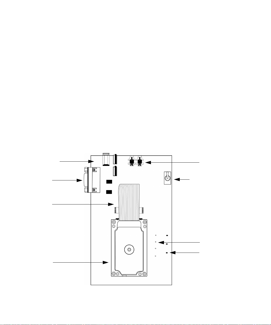
The following diagram illustrates the Interface and Test Board and major components.
power jack
Mic Spkr
RS-232
interface
22-pin
connector
cable
GPRS
Radio Modem
Interface and Test Board (on-board SIM configuration) – top view
microphone/
speaker jacks
transceiver
on/off switch
test point
LED
indicator
8 RIM OEM Radio Modem for GSM/GPRS Wireless Networks
Page 9
Connecting the SIM card
Connecting the SIM card
Note: This task only applies to the off-board SIM configuration.
The 6-pin flat SIM interface cable carries the data and power between the Interface and Test Board
SIM slot and the radio modem.
1. Remove the radio modem from the Interface and Test Board: unfasten the nuts and lift the radio
modem up and away from the Interface and Test Board.
2. On the underside of the modem, on the connector, push the two black tabs up from the
connector to widen the opening.
Underside of radio modem showing the 6-pin connector
3. With the blue side facing the Interface and Test Board, insert the end of the cable 6-pin cable into
the connector. Verify that the side with the bare pins is in direct contact with the pin side of the
connector.
Note: Do not force the cable into the connector.
4. Push the black tabs down toward the connector to secure the cable.
5. Repeat steps 2 through 4 to connect the 6-pin connector to the Interface and Test Board.
6. Re-attach the radio modem to the Interface and Test Board.
Getting Started Guide 9
Page 10

Chapter 1: Setting up the Interface and Test Board
Connecting the radio modem
Note: This step is only necessary if the radio modem is not already connected to the Interface and Test Board.
The 22-pin flat interface cable supplies clean, regulated power to the radio and carries most of the
data and all of the voice between the Interface and Test Board and the radio modem. This cable also
carries control and status signals, such as
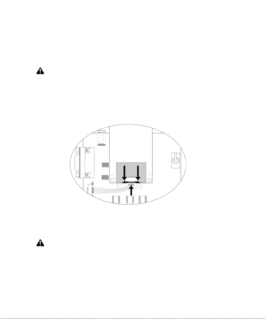
1. At the top of the radio modem, push the two black tabs up and away from the connector.
Connecting the 22-pin cable to the radio modem
2. With the blue side facing the Interface and Test Board, insert the end of the 22-pin cable into the
connector. Verify that the side with the bare pins is in direct contact with the pin side of the
connector.
ONI
.
Note: Do not force the cable into the connector.
3. At the top of the radio modem, push the black tabs down toward the connector to secure the
cable.
4. Repeat steps 1 through 3 for the 22-pin connector on the Interface and Test Board.
Connecting to the computer
Use the straight-through DB-9 serial cable to connect the Interface and Test Board to the computer.
Connect the male end of the cable to the Interface and Test Board. Connect the female end of the
cable to an available COM port on the computer.
10 RIM OEM Radio Modem for GSM/GPRS Wireless Networks
Page 11

Inserting the SIM card into the SIM card holder
Inserting the SIM card into the SIM card holder
Note: You must have a SIM card that is authorized for use by the appropriate GPRS network provider. The
authorization must also allow access to the Access Point Name (APN) that will be targeted.
Warning: To prevent damage to your SIM card, do not scratch or bend the card or expose it to static electricity
or wet conditions.
1. If you are using the on-board SIM configuration, turn the test board over to reveal the cut-out
that provides access to the SIM card holder on the underside of the radio modem.
Interface and Test Board (on-board SIM configuration) – bottom view
Getting Started Guide 11
Page 12

Chapter 1: Setting up the Interface and Test Board
2. Slide the SIM card holder in the direction of the arrow to unlock it, and then lift the cover open.
3. Slide the SIM card into the cover with the conductive side facing the leads on the board. The
notched end of the SIM card should align with the notch in the SIM card holder.
4. Close the cover. Slide the cover in the reverse direction of the arrow to lock it into place.
Connecting the antenna to the radio modem
The Integrator Kit includes a high-performance, 3 dBd-gain magmount antenna, which is
terminated by a screw-on SMA plug. The radio modem includes a snap-on MMCX jack.
1. Insert the antenna into the base. Turn the antenna until the two components are securely
fastened.
2. Insert the SMA cable connector into the MMCX connector and turn the SMA connector until the
two components are securely fastened.
SMA cable connector and MMCX connector
3. Insert the MMCX connector into the radio modem’s MMCX jack.
4. Position the antenna for optimal coverage. The magmount antenna provides optimum RF
performance when it is placed on a broad metal surface, such as the roof of a car. If you are
using the antenna inside a building, place the antenna near a window.
Connecting to an AC outlet
Plug the 5VDC, 2.4A, center-pin-positive power adapter into a wall outlet. Connect the other end to
the Interface and Test Board’s power jack.
Turning on the transceiver
Turn the switch to the
When the transceiver is on, the LED marked
TURNON
position to allow the transceiver of the radio modem to power up.
ONI
is lit
Connecting the headset
Insert the microphone plug into the microphone jack. Insert the speaker plug into the speaker jack.
12 RIM OEM Radio Modem for GSM/GPRS Wireless Networks
Page 13

Chapter 2
C onnecting the radio modem to a computer
To enable the radio modem to communicate with your computer, you must add the radio
modem to your computer, and add a dial-up network connection for the modem.
This section provides information on the following topics:
• Required information
• Connecting with Windows 2000
• Connecting with Windows 95/98
• Setting up HyperTerminal
Page 14

Chapter 2: Connecting the radio modem to a computer
Required information
Before you start, determine the access point name (APN) of your network.
Connecting with Windows 2000
Note: You must use Windows 2000 SP3 or later.
To connect the radio modem to your computer, you must perform the following tasks:
•add the modem
• add a dial-up connection
• edit registry settings
Add a modem
1. On the Start menu, select Settings > Control Panel. The Control Panel window appears.
2. Double-click the Phone and Modem Options icon. The Phone and Modem Options window
appears.
3. Click the Modems tab, as shown in the following diagram.
Modem Options window – Modems tab
4. Click Add. The Add/Remove Hardware Wizard appears.
14 RIM OEM Radio Modem for GSM/GPRS Wireless Networks
Page 15

Connecting with Windows 2000
5. Select the Don't detect my modem option. Click Next. The model selection window appears, as
shown in the following diagram.
Install New Modem window – model selection
6. In the Models list, select Standard 33600 bps modem. You do not need to choose a
manufacturer. Click Next. The port selection window appears, as shown in the following
diagram.
Install New Modem – port selection
7. Select the Selected ports option and click the COM port to which the radio modem is connected.
Click Next.
A window appears that indicates that your modem has been installed successfully.
8. Click Finish. The Phone and Modem Options window appears.
Getting Started Guide 15
Page 16

Chapter 2: Connecting the radio modem to a computer
9. On the Modems tab, select the modem that you added and click Properties. The Properties
window appears.
Modem Propert ies window – General tab
10. On the General tab, from the Maximum Port Speed drop-down list, select 115200.
11. Click the Advanced tab.
Modem Properties window – Advanced tab
16 RIM OEM Radio Modem for GSM/GPRS Wireless Networks
Page 17

Connecting with Windows 2000
12. In the Extra initialization commands field, type:
at+cgdcont=1,"IP","
apn_name
"
where apn_name is the access point name (APN) for your network
Note: If you do not have Windows 2000 SP3 installed, the Extra initialization command field has a limit of 40
characters. If your APN name results in an entry that is longer than 40 characters, install SP3. In Internet Explorer,
on the Tools menu, click Windows Update.
13. Click OK. The Phone and Modem Options window appears.
14. Click OK.
Add a connection
1. On the Start menu, select Settings > Network and Dial-up Connections. The Network and
Dial-up Connections window appears.
2. Double-click the Make New Connection icon. The Network Connection Wizard appears.
3. Click Next.
4. Select the Dial-up to the Internet option. Click Next. The Internet Connection Wizard appears.
5. Select the I want to set up my Internet connection manually option. Click Next. The Setting up
your Internet connection window appears.
6. Select the I connect through a phone line and a modem option. Click Next.
If you have more than one modem, the Choose Modem window appears. Select the modem that
you added earlier. Click Next.
The Step 1 of 3 window appears.
7. Clear the Use area code and dialing rules option.
8. In the Telephone number field, type *99#. Click Next. The Step 2 of 3 window appears.
9. Leave the User name and Password fields blank. Click Next. Two dialog boxes appear to
confirm that you have not set a user name and password.
10. In each dialog box, click Yes. The Step 3 of 3 window appears.
11. In the Connection name field, type a descriptive name for the new connection. Click Next. The
Set Up Your Internet Mail Account window appears.
12. Select No. Click Next. The Completing the Internet Connection Wizard window appears.
Getting Started Guide 17
Page 18

Chapter 2: Connecting the radio modem to a computer
13. Click Finish. The new connection appears in the Network and Dial-up Connections window.
Note: If you do not have Windows 2000 SP3 installed, clear the To connect to the Internet immediately option.
14. Right-click the new connection icon and click Properties. The Properties window appears.
15. Click the Networking tab, as shown in the following diagram.
Dial-up Properties window – Networking tab
16. Click Internet Protocol (TCP/IP) and click Properties. The Internet Protocol (TCP/IP) Properties
window appears, as shown in the following diagram.
Internet Protocol (TCP/IP) Properties window
17. Select the Obtain DNS server address automatically option.
18 RIM OEM Radio Modem for GSM/GPRS Wireless Networks
Page 19

Connecting with Windows 2000
18. Click OK. The Properties window appears.
19. Click the General tab and click Configure. The Modem Configuration window appears.
20. From the Maximum speed (bps) drop-down menu, select 115200.
21. Select the following options: Enable hardware flow control, Enable modem error control, and
Enable modem compression.
Modem Configuration window
22. Click OK.
23. Click OK.
Getting Started Guide 19
Page 20

Chapter 2: Connecting the radio modem to a computer
Change registry settings
Perform the following steps so that the modem disconnects and reconnects correctly.
1. In a command prompt, type:
regedit
The Registry Editor appears.
2. Click the following key:
HKEY_LOCAL_MACHINE > SYSTEM > CurrentControlSet > Control > Class >
{4D36E96D-E325-11CE-BFC1-08002BE10318} > xxxx > Hangup
where
xxxx
is the 4-digit number that corresponds to the standard 33600 bps modem that is
used to communicate with the RIM OEM Radio Modem.
Tip: To determine which 4-digit number to use, click the 4-digit key (such as 0001) and view the Model string.
The value data of the Model string should be Standard 33600 bps Modem.
The following diagram shows the Registry Editor window with the Hangup key selected.
Registry Editor with the Hangup key selected
20 RIM OEM Radio Modem for GSM/GPRS Wireless Networks
Page 21

Connecting with Windows 2000
3. Double-click on the 1 value.
4. In the Value data field, type: +++
5. Click OK.
6. On the Edit menu, click New > String Value. A new entry appears under the Name column in
the Registry Editor window.
7. Type 2 for the name.
8. Double-click on the 2 value that you just added. The Edit String window appears.
9. In the Value data field, type:
ATH<cr>
10. Click OK. The Registry Editor window appears as shown in the diagram below.
Registry Editor with new value added for Hangup key
11. Click OK.
12. Close the Registry Editor window.
13. Restart your computer for registry settings to take effect.
The RIM OEM Radio Modem connection is complete.
Getting Started Guide 21
Page 22

Chapter 2: Connecting the radio modem to a computer
Connecting with Windows 95/98
You must perform the following tasks to connect the radio modem to your computer:
•add the modem
• add a dial-up connection
Add a modem
1. From the Start menu, click Settings > Control Panel. The Control Panel window appears.
2. Double-click the Modems icon. The Modem Properties window appears, as shown in the
following diagram.
Modems Properties window
3. Click Add.
4. Select the Other option. Click Next.
5. Select the Don't detect my modem option. Click Next.
6. In the Models list, select Standard 28800 bps Modem. You do not need to select a manufacturer.
Click Next.
7. Select the COM port to which you connected the radio modem. Click Next.
8. Click Finish.
22 RIM OEM Radio Modem for GSM/GPRS Wireless Networks
Page 23

Connecting with Windows 95/98
Add a connection
1. On the Start menu, click Programs > Accessories > Communications > Dial-Up Networking.
2. Double-click the Make New Connection icon.
3. Type a descriptive name for the connection.
4. Select the Standard 28800 Modem that you installed.
5. Click Configure. The Properties window appears, as shown in the following diagram.
Modem Propert ies window – General tab
6. On the General tab, from the Port drop-down list, select the COM port to which the modem is
connected.
7. From the Maximum speed drop-down list, select 115200.
8. Click the Connection tab.
Getting Started Guide 23
Page 24

Chapter 2: Connecting the radio modem to a computer
Modem Properties window – Connection tab
9. Set the fields to the following values:
•From the Data bits drop-down list, select 8.
•From the Parity drop-down list, select None.
•From the Stop bits drop-down list, select 1.
10. Click Advanced. The Advanced Connection Settings window appears, as shown in the
following diagram.
.
Advanced Connection Settings window
11. In the Extra settings field, type:
at+cgdcont=1,"IP","apn_name"
where apn_name is the access point name (APN) for your network.
12. Click OK. The Modems Properties window appears.
24 RIM OEM Radio Modem for GSM/GPRS Wireless Networks
Page 25

Connecting with Windows 95/98
13. Click OK. The Make New Connection window appears.
14. Click Next.
15. In the Telephone number field, type *99#. Click Next.
16. Click Finish.
The new connection appears in the Network and Dial-up Connections window.
17. Right click on the connection icon that you created, and click Properties. The Properties window
appears.
18. Clear the Use area code and Dialing Properties option.
19. Click the Server Types tab. Set the fields to the following values:
•From the Type of Dial-Up Server pull-down list, select PPP.
•Under Advanced options, select the Enable software compression option.
•Under Allowed network protocols, select the TCP/IP option.
20. Click TCP/IP Settings. The TCP/IP Settings window appears.
21. Select the Server assigned IP address option.
22. Select the Server assigned name server addresses option.
23. Select the Use IP header compression and Use default gateway on remote network options.
24. Click OK. The Properties window appears.
25. Click OK.
The modem is now set up for dialup access.
Getting Started Guide 25
Page 26

Chapter 2: Connecting the radio modem to a computer
Setting up HyperTerminal
You can use HyperTerminal to send AT commands to the OEM radio modem.
1. On the Windows Start menu, click Programs > Accessories > Communications >
HyperTerminal.
The Connection Description window appears.
2. Type a name and select an icon. Click OK.
The Connect To window appears.
3. From the Connect using drop-down menu, select the COM port to which the radio modem is
connected. Click OK.
The Properties window appears.
4. Set the fields as follows:
• Bits per second: 115200
• Data bits: 8
• Parity: None
• Stop bits: 1
• Flow control: Hardware
HyperTerminal Connection Properties
5. Click OK. The modem is now ready to receive AT commands.
26 RIM OEM Radio Modem for GSM/GPRS Wireless Networks
Page 27

Page 28

© 2002 Research In Motion Limited
Published in Canada
 Loading...