

BK Radio P150S, P-150, P-400, P-500, P-800 Service Manual
...
Index
Section 1 - General Information
Section II - Installation and Programming
Section III - Operation
Section IV - Theory of Operation
Section V - Maintenance
Section VI - Illustrated Parts List

Section i
General information
1.1 introduction .................................................................................................................1-1
1.2 deScription ....................................................................................................................1-1
1.3 technical characteriSticS ....................................................................................1-1
1.4 factory optionS ..........................................................................................................1-2
1.5 acceSSorieS .................................................................................................................1-2
1.6 licenSe requirementS ..............................................................................................1-2
1.7 radio controlS ............................................................................................................ 1-3
1.8 radio tier verSionS .................................................................................................... 1-5
1.9 Service information .................................................................................................. 1-5
Section ii
inStallation and proGramminG
2.1 General information ................................................................................................ 2-1
2.1.1 unpackinG and inSpectinG equipment ...................................................................2-1
2.1.2 Battery inStallation ...................................................................................................2-1
2.1.3 antenna inStallation ....................................................................................................2-2
2.2 how to proGram radioS .......................................................................................... 2-2
2.2.1 keypad proGramminG ...................................................................................................2-2
2.2.1.1 programming p25 id unit call/receive list .........................................................2-3
2.2.1.2 programming user Selectable transmit tones .....................................................2-4
2.2.1.3 programming user Selectable network access codes .......................................2-5
2.2.1.4 programming user Selectable talkgroup ids .......................................................2-6
2.2.1.5 programming channel parameters ........................................................................2-7
Channel Label ...........................................................................................................2-8
Receive Frequency ...................................................................................................2-8
Service Manual - KNG Portables - Index page i

Receive Mode ...........................................................................................................2-8
Receive Code Guard.................................................................................................2-9
Receive Network Access Code .................................................................................2-9
Squelch Mode ...........................................................................................................2-9
Transmit Frequency ................................................................................................2-10
Transmit Mode ........................................................................................................2-10
Channel Bandwidth .................................................................................................2-10
Transmit Code Guard .............................................................................................2-11
Transmit Network Access Code ..............................................................................2-11
Talkgroup ID ............................................................................................................2-12
Encryption Secure Mode (Encrypted models).........................................................2-12
Encryption Key (Encrypted models) ........................................................................2-12
Encryption Key Lock (Encrypted models) ...............................................................2-13
Low Power Lock ......................................................................................................2-13
2.2.1.6 programming Zone parameters ...........................................................................2-14
Zone Label ..............................................................................................................2-14
Priority 1 Channel....................................................................................................2-15
Transmit on Priority 1 Channel ................................................................................2-15
Priority 2 Channel ...................................................................................................2-15
Automatic Number Identication (ANI) Mode ..........................................................2-15
Automatic Number Identication (ANI) ID ...............................................................2-16
Disable Zone Cloning ..............................................................................................2-16
2.2.1.7 programming Global parameters ........................................................................2-17
Global Priority 1 Channel ........................................................................................2-17
Global Priority 1 Zone .............................................................................................2-18
Tx on Global Priority 1 Channel ..............................................................................2-18
Global Priority 2 Channel ........................................................................................2-18
Global Priority 2 Zone .............................................................................................2-18
Scan Hold Time .......................................................................................................2-19
Busy Channel Mode ................................................................................................2-19
TX Time Out Timer ..................................................................................................2-19
Backlight Mode........................................................................................................2-19
Backlight Duration ...................................................................................................2-20
Password ................................................................................................................2-20
2.2.1.8 keypad programming characters ........................................................................2-20
2.2.2 radio cloninG .................................................................................................................2-21
2.2.2.1 knG to knG cloning .............................................................................................2-21
2.2.2.2 knG to legacy radio cloning ..............................................................................2-22
2.2.2.3 legacy radio to knG cloning ..............................................................................2-25
2.2.3 pc radio editinG .............................................................................................................2-27
2.2.3.1 program Setup .......................................................................................................2-27
2.2.3.2 reading and writing radio information ..............................................................2-29
2.2.3.3 programming Zone information ...........................................................................2-30
Channel Information ................................................................................................2-30
Encryption Channel Settings ...................................................................................2-38
2.2.3.4 Zone Settings .........................................................................................................2-39
Service Manual - KNG Portables - Index page ii

2.2.3.5 Global Settings .......................................................................................................2-42
General Tab .............................................................................................................2-42
Features Tab ...........................................................................................................2-47
Unit Call List Tab .....................................................................................................2-49
Keypad Editing Lockouts Tab ..................................................................................2-50
Menus and Controls Tab .........................................................................................2-50
Pick Lists Tab ..........................................................................................................2-52
Encryption Tab ........................................................................................................2-53
Tactical OTAR Tab ...................................................................................................2-54
2.2.4 encryption key fill .....................................................................................................2-56
2.2.5 tactical otar Setup ....................................................................................................2-56
2.2.5.1 Key Source Radio Conguration ..........................................................................2-56
2.2.5.2 Target Radio Conguration ...................................................................................2-59
2.2.5.3 tactical otar quick reference ............................................................................2-61
2.2.5.4 tactical otar error codes ...................................................................................2-61
2.2.6 vote Scan Setup ............................................................................................................2-62
2.2.6 ctcSS code Guard valueS .........................................................................................2-63
2.2.7 cdcSS code Guard valueS ........................................................................................2-63
Section iii
operation
3.1 BaSic operation ...........................................................................................................3-1
3.1.1 receive ................................................................................................................................3-1
3.1.2 tranSmit .............................................................................................................................3-1
3.2 code Guard operation .............................................................................................. 3-2
3.2.1 analoG Squelch control ...........................................................................................3-2
3.2.2 apco project 25 Squelch control .........................................................................3-2
3.2.3 code Guard receive ......................................................................................................3-2
3.2.4 code Guard tranSmit ....................................................................................................3-3
3.3 mixed mode operation ...............................................................................................3-3
3.3.1 mixed mode talkBack ....................................................................................................3-3
3.4 encryption operation .............................................................................................. 3-4
3.4.1 required Setup ................................................................................................................3-4
Service Manual - KNG Portables - Index page iii

3.4.2 operation ...........................................................................................................................3-4
3.4.3 tranSmit encryption key Selection .......................................................................3-4
3.4.4 ZeroiZation ........................................................................................................................3-5
3.4.5 over-the-air-rekeyinG (otar) ....................................................................................3-5
3.4.6 keySet viewinG and SelectinG ...................................................................................3-6
3.4.7 tactical otar option (kZa0584) ..................................................................................3-7
3.5 Scan operation optionS ........................................................................................... 3-8
3.5.1 channel Scan (Scn) ........................................................................................................3-8
3.5.2 ScanninG code Guarded channelS .........................................................................3-9
3.5.3 vote ScanninG ..................................................................................................................3-9
3.5.4 nuiSance channel delete ...........................................................................................3-9
3.5.5 tranSmittinG with Scan on ........................................................................................3-9
3.5.6 talkBack Scan ...............................................................................................................3-10
3.5.7 priority Scan (pri) ........................................................................................................3-10
3.5.8 Scan liSt add/delete ...................................................................................................3-12
3.5.9 Zone Scan (ZScn) ...........................................................................................................3-12
3.5.10 Zone Scan liSt add/delete .....................................................................................3-12
3.6 emerGency SiGnallinG optionS ........................................................................... 3-13
3.6.1 placinG an emerGency call ....................................................................................3-13
3.6.2 receivinG an emerGency SiGnal .............................................................................3-14
3.7 unit-to-unit call optionS ....................................................................................... 3-14
3.7.1 individual call (u2u) ....................................................................................................3-14
3.7.2 unit-to unit callBack .................................................................................................3-15
3.7.3 call liSt proGramminG ..............................................................................................3-15
3.8 pick liSt optionS ........................................................................................................ 3-16
3.8.1 cxcSS code Guard (tcG/rcG) ....................................................................................3-16
3.8.2 nac (tnac/rnac) .............................................................................................................3-17
3.8.3 tGid (utG) ..........................................................................................................................3-17
3.9 General optionS ........................................................................................................ 3-18
3.5.1 BackliGht (liGt) .............................................................................................................3-18
Service Manual - KNG Portables - Index page iv

3.9.2 keypad lock ....................................................................................................................3-18
3.9.3 monitor (mon) .................................................................................................................3-19
3.9.4 repeater talkaround (ta) ........................................................................................3-20
3.9.5 Surveillance mode (Surv) .........................................................................................3-20
3.9.6 Squelch adjuSt (Sql) .................................................................................................3-21
3.9.7 tx diGital (txd) ................................................................................................................3-21
3.9.8 tx power (lpw) ...............................................................................................................3-22
3.9.9 Zone Select (Zon) ..........................................................................................................3-23
Section iv
theory of operation
4.1 introduction ................................................................................................................. 4-1
equipment deScription .............................................................................................. 4-1
4.2
4.3 theory of operation .................................................................................................. 4-1
4.3.1 SyStem Board ...................................................................................................................4-1
Core Microprocessor ..............................................................................................................4-1
Voltage Regulators .................................................................................................................4-1
Baseband Signal Processor ...................................................................................................4-2
Audio Power Ampliers ..........................................................................................................4-2
4.3.2 rf Board .............................................................................................................................4-2
RF Input/Output .....................................................................................................................4-3
Synthesizer ...........................................................................................................................4-3
Transmitter .............................................................................................................................4-4
Receiver .................................................................................................................................4-6
Section v
maintenance
5.1 introduction ................................................................................................................. 5-1
5.2 teSt equipment required ......................................................................................... 5-1
5.3 aliGnment procedureS ............................................................................................. 5-1
Service Manual - KNG Portables - Index page v

5.3.1 teSt Setup ..........................................................................................................................5-1
5.3.2 aliGnment order .............................................................................................................5-2
Reference Frequency ............................................................................................................5-2
Transmit Power Curve ...........................................................................................................5-2
Transmit Power Levels ...........................................................................................................5-3
FM Modulation .......................................................................................................................5-3
Receiver Alignment ................................................................................................................5-3
Squelch Adjustment ...............................................................................................................5-3
Vote Scan ...............................................................................................................................5-4
5.4 diSaSSemBly/aSSemBly .............................................................................................. 5-4
5.4.1 Battery removal .............................................................................................................5-4
5.4.2 antenna removal ............................................................................................................5-4
5.4.3 radio diSaSSemBly ..........................................................................................................5-4
Assemblies .............................................................................................................................5-4
RX/TX Board Assembly .........................................................................................................5-4
Systems Board Assembly ......................................................................................................5-5
Shields ...................................................................................................................................5-5
5.4.4 aSSemBly ............................................................................................................................5-5
5.5 overhaul ........................................................................................................................5-5
5.5.1 viSual inSpection ............................................................................................................5-5
5.5.2 cleaninG .............................................................................................................................5-6
5.5.3 repair ..................................................................................................................................5-7
5.6 equipment Setup diaGramS ...................................................................................... 5-7
Section vi
illuStrated partS liSt
6.1 introduction ................................................................................................................. 6-1
6.2 partS liSt deScription .............................................................................................6-1
6.3 aSSemBly drawinG SymBolS .................................................................................... 6-1
6.4 interconnect diaGram ............................................................................................. 6-2
6.5 final aSSemBly..............................................................................................................6-3
partS liSt ....................................................................................................................................6-3
Service Manual - KNG Portables - Index page vi

aSSemBly diaGram ...................................................................................................................6-5
6.6 front aSSemBly ........................................................................................................... 6-7
partS liSt ....................................................................................................................................6-7
aSSemBly diaGram ...................................................................................................................6-9
6.7 Back aSSemBly ............................................................................................................6-11
partS liSt ..................................................................................................................................6-11
aSSemBly diaGram .................................................................................................................6-13
6.8 SyStemS aSSemBly ..................................................................................................... 6-15
partS liSt ..................................................................................................................................6-15
aSSemBly diaGram .................................................................................................................6-17
6.9 SyStemS Board ........................................................................................................... 6-19
partS liSt ..................................................................................................................................6-19
partS layout ...........................................................................................................................6-31
SchematicS ...............................................................................................................................6-33
6.10 rx/tx aSSemBly .........................................................................................................6-43
partS liSt ..................................................................................................................................6-43
aSSemBly diaGram .................................................................................................................6-45
6.11 rx/tx BoardS..............................................................................................................6-47
6.11.1 p150 ....................................................................................................................................6-47
Parts List ............................................................................................................................6-47
Parts Layout .......................................................................................................................6-63
Schematics .........................................................................................................................6-65
6.11.2 p400 ....................................................................................................................................6-75
Parts List ............................................................................................................................6-75
Parts Layout .......................................................................................................................6-91
Schematics .........................................................................................................................6-93
6.11.3 p500 ..................................................................................................................................6-103
Parts List ..........................................................................................................................6-103
Parts Layout .....................................................................................................................6-119
Schematics .......................................................................................................................6-121
Service Manual - KNG Portables - Index page vii

Section vii
inteGrated circuit data
7.1 introduction ................................................................................................................. 7-1
7.2 BaSic loGic elementS ................................................................................................7-1
7.3 BaSic op-amp circuitS ................................................................................................ 7-2
7.4 Surface mount componentS .................................................................................. 7-7
Service Manual - KNG Portables - Index page viii

Section i
General information
1.1 introduction
This manual contains information about the physical, mechanical, and electrical characteristics of the BK
Radio KNG Series APCO Project 25 digital radios. KNG Portable radios are available in VHF, UHF and
800 MHz models.
1.2 deScription
The KNG is a handheld FM transceiver designed for use in domestic and international Land Mobile
services. The radio supports standard analog FM and digital C4FM modulation pursuant to TIA-102.
BAAD (Project 25 Common Air Interface Description for Conventional Channels) et al. The radio can be
congured for as many as 512 channels that can be arranged into as many as 32 zones. Each channel
species unique receive and transmit RF frequencies, sub-audible squelch, digital control parameters,
etc.
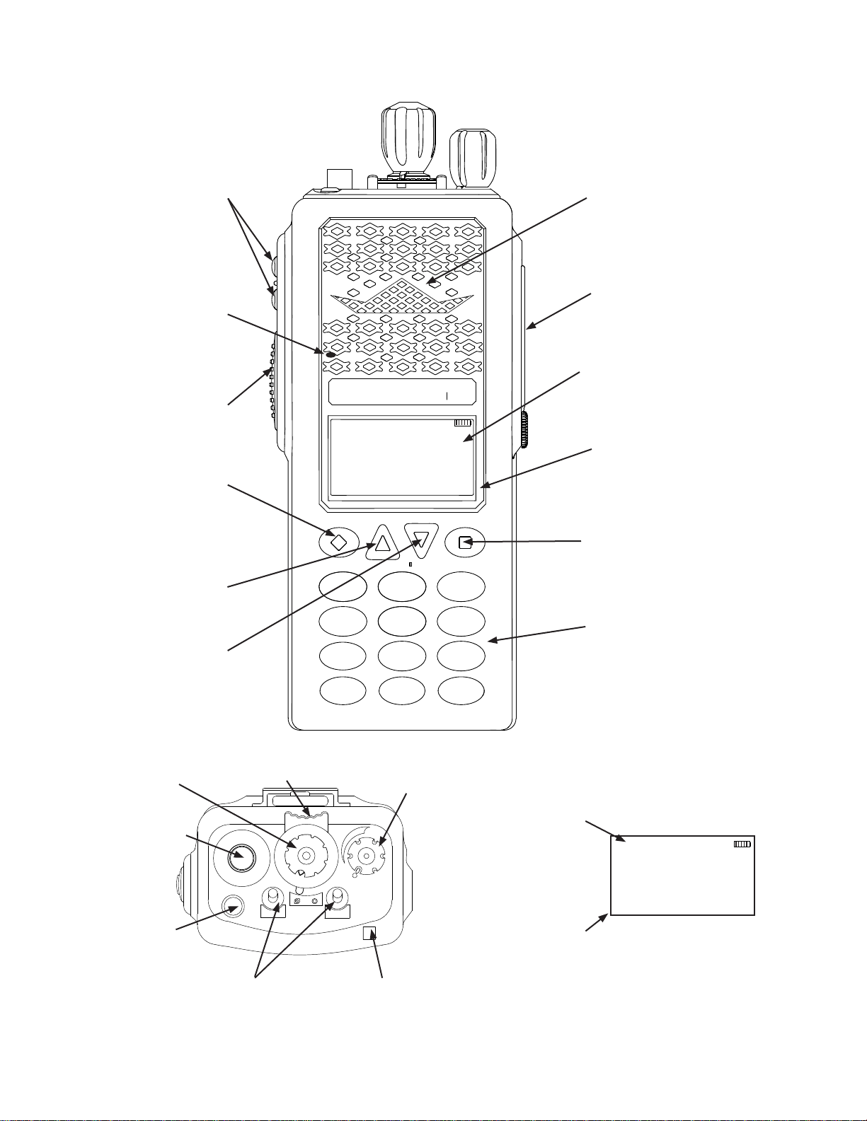
Top panel controls include on/off/volume, channel rotary selector, a concentric two-position switch, an
orange momentary switch, and two toggle switches with dealer programmable function. The side panel
contains a PTT switch, and two programmable push buttons. Connectors are provided via the side
connector for external speaker, microphone, programming, and options. Some models include a front
panel LCD display for status information, four programmable push buttons, and a keypad for tailoring
radio operation.
1.3 technical characteriSticS
power Supply: ................................................................. One rechargeable lithium-ion battery pack
with temperature sensor or one alkaline battery pack.
operational featureS: Programmable Switches, Per Channel Analog/Digital/Mixed-Mode, RX
and TX Dual Priority Scan, Frequency Display, Transmit Time-Out Timer, User Selectable Scan, Scan
Delay, Busy Channel Indicate / Lockout, Tone Code Guard (CTCSS), DTMF/ANI Encode, Digital Code
Guard (CDCSS), Nuisance Channel Delete, Talkback Scan and User Selectable Code Guard.
channelS with variaBle Zone SiZe: ................... 512
ZoneS: ............................................................................ Up to 32
operatinG voltaGe: ................................................. 10 VDC Nominal
phySical dimenSionS: .............................................. Weight: 9 oz. (15 oz. with battery)
Width: 2.5 in. (63.5 millimeters)
Depth: 1.8 in. (45.7 mm.)
Height: 5.5 in. (139.7 mm.)
channel SpacinG: ...................................................... 25/12.5 kHz
channel incrementS: .............................................. 1.25 kHz
antenna type: ............................................................. Helical wound molded rubber ex (standard)
max current drain: .................................................. Transmit High Power: 1.5 amps
Receive: 255 mA
Standby: 100 mA
operatinG temperature: ...................................... -30° to +60° C
BK Radio Page 1-1

General information
Specication p-150 p-400 p-500 p-800
Frequency Range 136 - 174 MHz 380 - 470 MHz 440 - 520 MHz 763 - 870 MHz
FCC ID K95KNGP150 K95KNGP400 K95KNGP500 K95KNGP800
receiver
Sensitivity: 12db SINAD -121 dBm -119 dBm -121 dBm -119 dBm
P25 Sensitivity: 5% BER -121 dBm -119 dBm -121 dBm -119 dBm
Adjacent Channel Rejection
Per TIA/EIA-603 2.1.6
P25 Adjacent Channel Rejection 60 dB 60 dB 60 dB 60 dB
Spurious and Images 80 dB 80 dB 85 dB 75 dB
Intermodulation Rejection 78 dB 75 dB 77 dB 75 dB
Audio Response +1dB / -3dB +1dB / -3dB +1dB / -3dB +1dB / -3dB
Audio Distortion at 500mW 2 % 2 % 2 % 2 %
RX Current Draw 255 mA 255 mA 255 mA 255 mA
transmitter
RF Power 6 / 5 / 1 Watts 5 / 4 / 1 Watts 5 / 4 / 1 Watts 3 / 1 Watts
Frequency Stability 1.5 ppm 1.5 ppm 1.5 ppm 1.5 ppm
Modulation Deviation 5 (2.5) kHz 5 (2.5) kHz 5 (2.5) kHz 5 (2.5) kHz
Audio Distortion 3 % 3 % 3 % 3 %
FM Hum & Noise 50 (45) dB 50 (45) dB 50 (45) dB 50 (45) dB
Spurious and Harmonics 75 dB 75 dB 75 dB 75 dB
Current Draw @ High Power 1500 mA 1500 mA 1500 mA 1500 mA
Audio Response +1dB / -3dB +1dB / -3dB +1dB / -3dB +1dB / -3dB
Modulation 16K0F3E
80 (70) dB 78 (67) dB 79 (67) dB 72 (63) dB
(11K0F3E)
8K10F1E
(8K10F1D)
1.4 factory optionS
Factory installed options are referenced on the back of the radio.
The following list includes options available at the time of printing.
kZa0558 Intrinsically Safe Certication
kZa0577 AES and DES Encryption
kZa0578 Over-the-Air Rekeying (OTAR)
kZa0581 Vote Scan Operation
kZa0584 Wireless Tactical OTAR
1.5 acceSSorieS
Use only BK Radio approved supplied or replacement antennas, batteries, and accessories. Use of nonBK Radio approved antennas, batteries, and accessories may exceed the FCC RF exposure guidelines.
For a list of BK Radio approved accessories visit the following web site: http://www.relm.com.
1.6 licenSe requirementS
This equipment must be licensed by the Federal Communications Commission (FCC) before it may be
used. Your BK Radio dealer can assist you in ling the appropriate application with the FCC and program
each radio with your authorized frequencies and signaling codes.
Page 1-2 Service Manual - KNG Portables
General information
KNG
ABC
DEF
GHI
JKL
MNO
PQRS
TUV
WXYZ
*
#
1
2
3
4
7
8
9
5
6
0
BK RADIO
15
1
2
3
4
5
6
7
8
9
11
10
12
13
14
16
SCAN
PRI
VOL
on/off volume
channel Select
collar Switch
antenna
connector
emergency
Button
toggle Switches
led indicator
Ch 1
KNG -P25
171.58500 MHz
liGt t/a menu lck
txd Scn
{
programmable
alphanumeric lines
Status indicators
menu items
alphanumeric display
1.7 radio controlS
programmable
Side Buttons
microphone
push-to-talk
diamond
Button
up arrow
Button
txd Scn
Ch 1
KNG -P25
171.58500 MHz
liGt t/a menu lck
Speaker
Side connector
alphanumeric
display
programmed
menu items
Square
Button
keypad
down arrow
Button
BK Radio Page 1-3
General information
Status indicators
rxd, rxa
txd, txa Transmit Digital, Transmit Analog
rta Repeater Talk Around Enabled
p1, p2 Priority 1 Channel, Priority 2 Channel
,
Scn
Receiver Signal Strength
Receive Digital, Receive Analog,
Hold Time Active
Encrypted, Clear
Scan Channel,
Flashing 'SCN' = Scan in Progress.
Unit-to-Unit operation active
Battery Level Indicator
alphanumeric label options
NOTE: Three channel information lines are
programmable with PC Radio Editor Software.
channel
number
channel
label
frequency Operating Frequency of Currently
received
unit id
received
talk Group
id
rx pick
list
Selection
tx pick
list
Selection
Zone
label
Zone and
channel
Channel Number of Currently Selected
Channel or Active Scanned Channel
Alphanumeric Label of Currently
Selected Channel or Active Scanned
Channel
Selected Channel or Active Scanned
Channel
P25 ID of the radio transmitting the
message currently being received
If the received ID is programmed
in your radio's Call List, the
corresponding label will be displayed
P25 Talk Group ID of the radio
transmitting the message currently
being received
NAC, TGID or Code Guard currently
selected from the programmable Pick
Lists
NAC, TGID or Code Guard currently
selected from the programmable Pick
Lists
Label of Currently Selected Zone
Currently Selected Zone and Channel
Numbers
Buttons and labels
NOTE: The Diamond, Up Arrow, Down Arrow, and
Square buttons are programmable with PC Radio
Editor Software. The programmed functions are
activated by pressing the associated button. Active
functions are indicated by a highlighted background.
= Active, Scn = Inactive.
Scn
emr Emergency Operation
lck Keypad Lockout
liGt Keypad and Display Backlight
lpw Transmit in Low Power Mode
menu Open the programmed radio menu
mon Monitor
nuiS Nuisance Channel Delete
pr1 Set Priority 1 Channel
pScn Priority Scan
rky Request OTAR Encryption Rekey
rnac User Selectable Receive NAC
rcG User Selectable RX CTCSS/CDCSS
Code Guard
(Analog or Mixed Mode Operation)
Scn Channel Scan
Surv Surveillance Mode
Sql Squelch Adjust
t/a Repeater Talkaround
txd Transmit Digital
(Mixed Mode Operation)
txS Transmit Secure
(Encrypted Models)
u2u Unit-to-Unit Call
(Digital Operation Only)
key User Selectable Encryption Key
(Encrypted Models)
kSet User Selectable Encryption Keyset
(Encrypted OTAR Models)
tnac User Selectable TX NAC
(Digital or Mixed Mode Operation)
tGid User Selectable Talk Group
(Digital or Mixed Mode Operation)
tcG User Selectable TX CTCSS/CDCSS
Code Guard
(Analog or Mixed Mode Operation)
Zer Zeroize Encryption Keys and
Password
(Encrypted Models)
Zon Channel Zone Select
ZScn Zone Scan
Page 1-4 Service Manual - KNG Portables
General information
ABC
DEF
GHI
JKL
MNO
PQRS
TUV
WXYZ
*
#
1
2
3
4
7
8
9
5
6
0
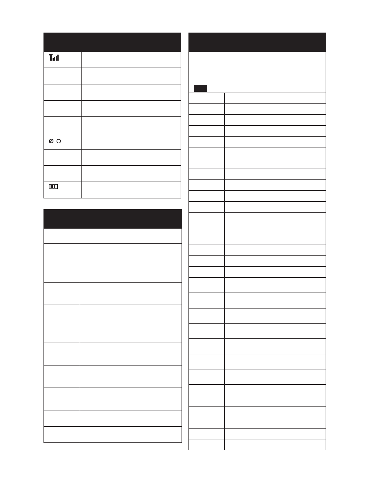
1.8 radio tier verSionS
Some KNG portable radio models are available in various levels of eld-user access called tiers. All tiers
may not be available in all frequency ranges or radio models.
tier i
Tier I models have no keypad or display. End-user function access and control is
limited to items assigned to the top and side programmable switches and buttons.
tier ii
Tier II models include the three line display and limited keypad. End-user access
is limited to functions that do not require a full keypad. Functions are determined
by items programmed to the Diamond, Up/Down and Square buttons as well as
items assigned to the top and side programmable switches and buttons.
tier iii
Tier III models include a full keypad. Access to all functions and controls, including
eld-programming, are are determined by PC programming.
1.9 Service information
If you need service, contact your local BK Radio dealer equipped to service your radio. If you nd it
impractical to have service performed by your local dealer, contact BK Radio at the address below:
Bk radio attention: customer Service
7100 Technology Drive
West Melbourne, FL 32904
Voice (800) 422-6281
FAX (321) 953-7986
BK Radio Page 1-5

General information
BLANK PAGE
Page 1-6 Service Manual - KNG Portables
Section ii
+
TS
ON
-
Release Tab
inStallation and proGramminG
2.1 General information
This section contains information concerning the installation and programming of the BK Radio KNG
APCO Project 25 digital radios.
2.1.1 unpackinG and inSpectinG equipment
Exercise extreme care when unpacking the equipment. Make a visual inspection of the unit for evidence
of damage incurred during shipment. If a claim for damage is to be made, save the shipping container
to substantiate the claim. The claim should be promptly led with the transportation company. It would
be advisable to retain the container and packaging material after all equipment has been removed in the
event that equipment storage or reshipment should become necessary.
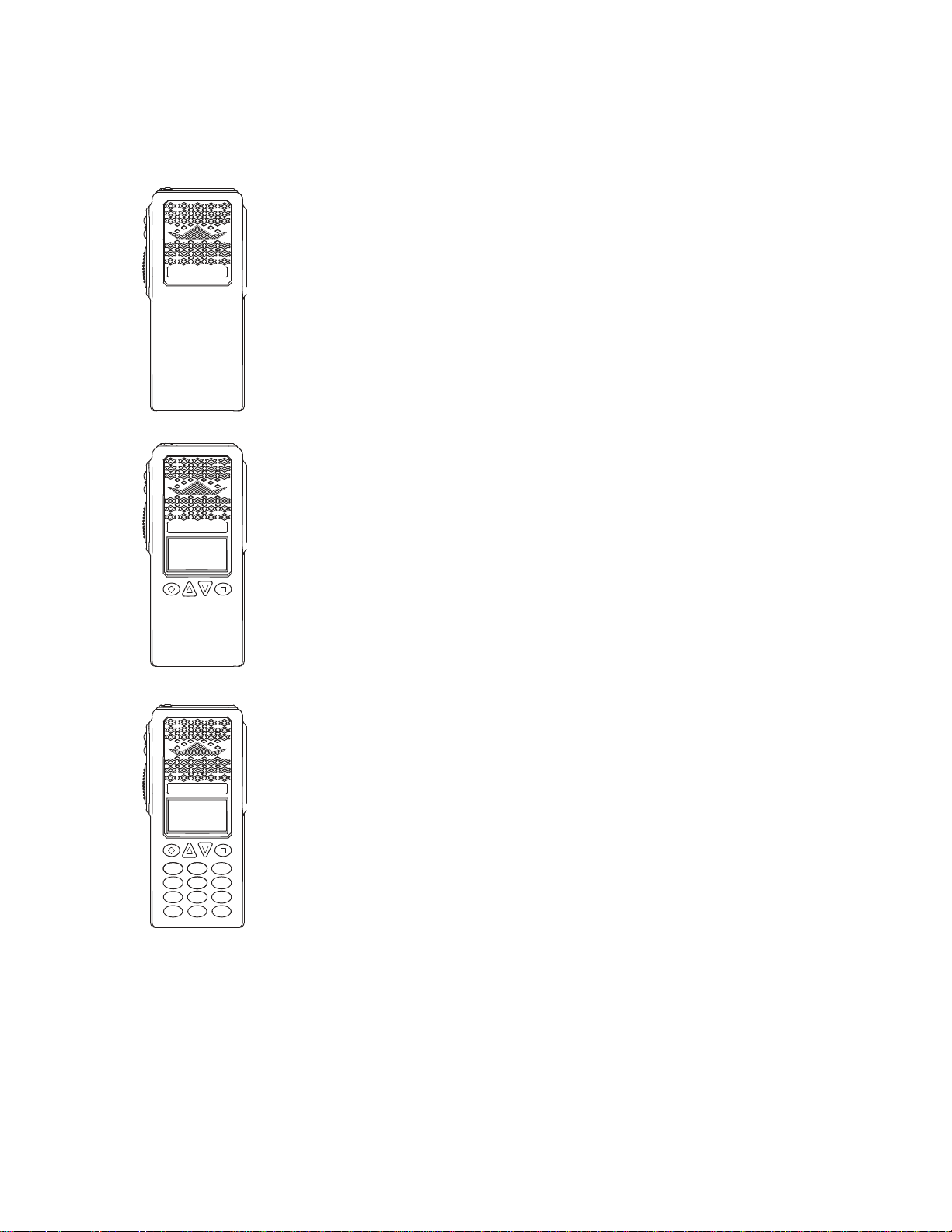
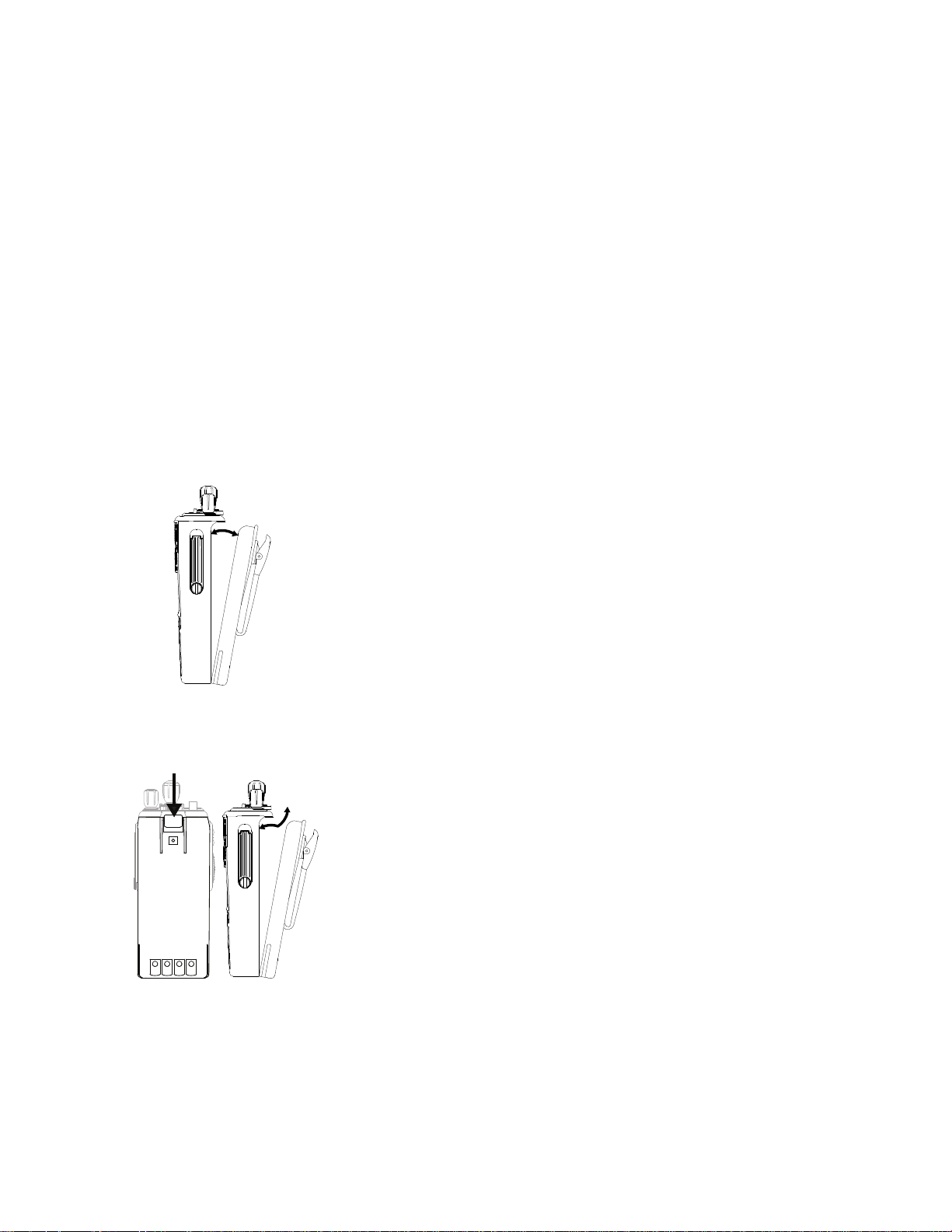
2.1.2 Battery inStallation inStallinG the Battery
1. Turn the radio off.
2. Align the tabs on the bottom of the battery with the slots on the radio.
3. Push the top of the battery toward the radio until release tab “clicks”
into place.
removinG the Battery
1. Slide the release tab toward the bottom of the radio.
2. Pull the top of the battery out.
(Approximately 30o)
3. Pull up to remove the battery pack.
note: All information programmed into the radio is maintained even when the battery pack is removed.
BK Radio battery packs are available in a variety of capacities and types for special applications.
Rechargeable battery packs can be charged separately or while attached to a radio.
Periodically check the contacts on the battery pack for dirt that could prevent a good electrical contact
with the charging base.
BK Radio Page 2-1
installation and programming
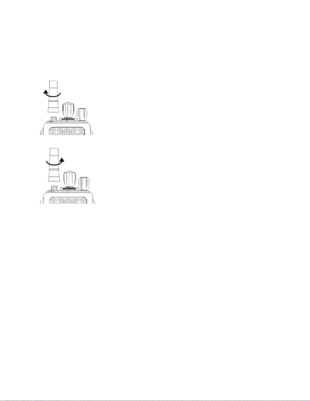
2.1.3 antenna inStallation
NOTE: Transmitting without an antenna could result in damage to your radio.
Use RELM/BK Radio approved antennas only. Use of non-qualied or mismatched antennas could result
in diminished radio operation. Published radio specications cannot be guaranteed with non-approved
antennas. Bent, broken or damaged antennas should be replaced.
inStallinG the antenna
Insert the radio’s antenna connector into the threaded connector of the
antenna and turn it clockwise until it is rmly seated.
removinG the antenna
Holding the base, turn the antenna counterclockwise until released.
2.2 how to proGram radioS
There are three different ways to program BK Radio radios:
• BY KEYPAD A radio can be programmed with its keypad providing the keypad programming functions
have been enabled via PC. That procedure is described in this section.
• BY CLONING You can transfer the programmed settings to another radio of the same frequency band
by using a cloning cable. See “Radio Cloning” section of this manual.
• BY COMPUTER With a computer, KNG programming software, and an interface cable. Contact BK
Radio for the required programming cable and software. See “PC Radio Editing” section of this manual.
2.2.1 keypad proGramminG
If enabled via PC programming, the radio’s Picklists and Individual Call List information can be edited
using the keypad. In addition, programmed channel, zone and some global settings can also be
programmed. Check with your RELM/BK Radio dealer or communications ofcer for information on the
programmed functions of your radio.
Programmable categories include Individual P25 ID Quick Call/Receive List, User Code Guard List,
User NAC List, User Talk Group ID List and Keypad Programming of Channel, Zone and Global radio
parameters.
Page 2-2 Service Manual - KNG Portables
installation and programming
Ch 1
KNG - P25
171.5850 0 MHz
liGt t/a menu lck
rxd Scn
Keypad Prog
User Tones
Call List
ESC ▲ ▼ ENT
Enter Password
000000
eSc clr ent
ESC ▲ ▼ ENT
Call List
Call 1
Call 2
Talkaround
Tx Power
Keypad Prog
ESC ▲ ▼ ENT
ESC CLR ▼ ENT
Call 1
Call 1 Label
1234567
eSc clr Bck ent
Call 1
1234567
ESC CLR ▼ ENT
Call 1
C a l l 1 L a b e l
123 4 56 7
eSc clr ent
Call 1
Call 1 Label
123 4 56 7
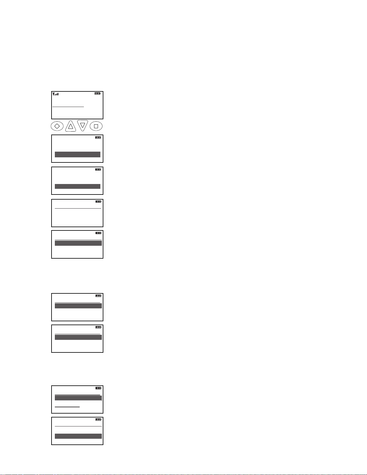
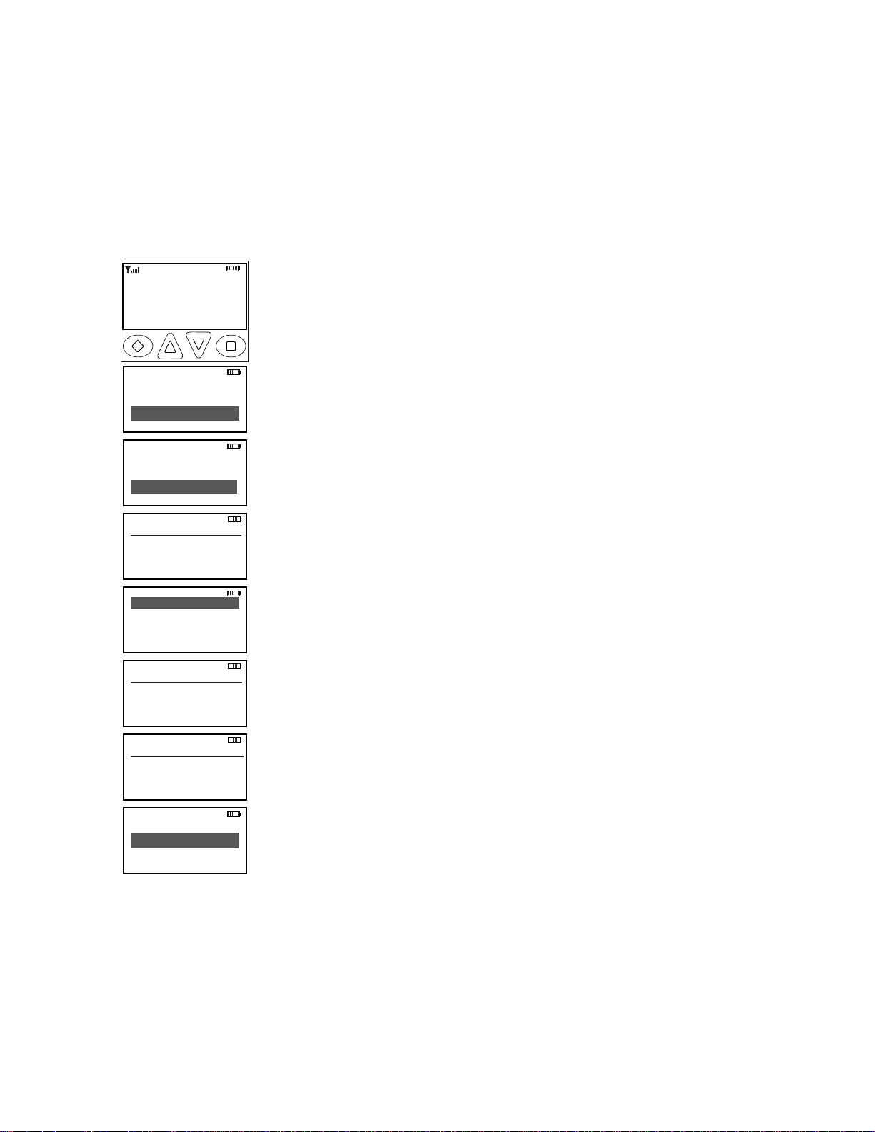
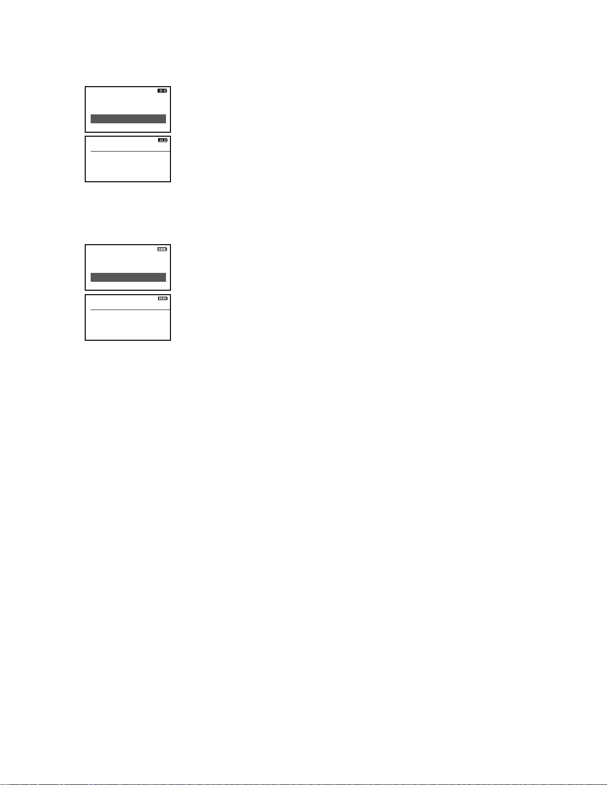
2.2.1.1 proGramminG p25 id unit call/receive liSt
The KNG can be pre-programmed with up to 100 Project 25 IDs and labels. If ‘RX’d Unit ID’ is
designated as a display line, the P25 ID of the radio sending the call will be shown when receiving a
digital signal. If the P25 ID of the received call is programmed in the Call List, the alphanumeric label
associated with the ID will be displayed. If the P25 ID is not in the Call List, the numeric P25 ID will be
displayed.
To enter P25 Call List programming:
1. Press the Menu button.
2. Use the up/down buttons to highlight Keypad Prog.
3. Press the ‘ENT’ button.
4 Use the up/down buttons to highlight Call List.
5. Press ‘ENT’.
6. Use the keypad to enter the six digit password.
7. Press ‘ENT’.
The labels of the programmed P25 ID’s will be displayed
8. Use the up/down buttons to highlight the P25 ID you wish to edit.
9. Press ‘ENT’.
The display shows the alphanumeric label and P25 ID of the selected ID.
editing the label
editing the id number
BK Radio Page 2-3
1. Use the down arrow button to highlight the label.
2. Press the ‘CLR’ button to clear the label.
3. Use the keypad to select the desired character.
(See Keypad Character Chart.)
If necessary, use the BCK button to move back one character.
Labels can contain up to thirteen characters.
4. Press the ‘ENT’ button to save the label.
1. Use the down arrow button to highlight the ID.
2. Press the ‘CLR’ button to clear the ID.
3. Use the keypad to select the desired ID number. (Up to seven digits.)
4. Press the ‘ENT’ button to save the ID.
installation and programming
Ch 1
KNG - P25
171.5850 0 MHz
liGt t/a menu lck
rxd Scn
Talkaround
Tx Power
Keypad Prog
ESC ▲ ▼ ENT
Enter Password
000000
eSc clr ent
Call List
User Tones
User TGIDs
ESC ▲ ▼ ENT
User Tones
1 - 100.0
2 - 141.3
ESC ▲ ▼ ENT
TONE 01
100 .0
eSc clr ent
TONE 01
# for CDCSS
000.0
eSc clr ent
TONE 01
# for CTCSS
D000-
eSc +/- clr ent
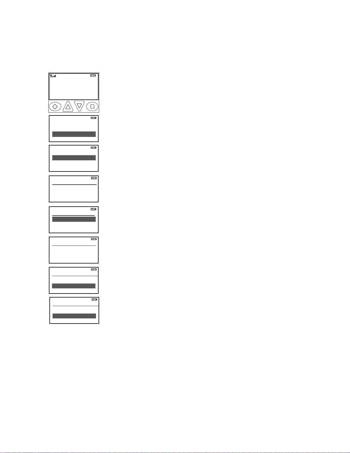
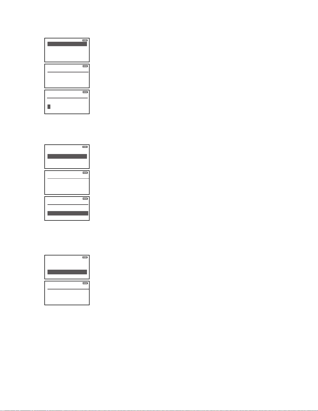
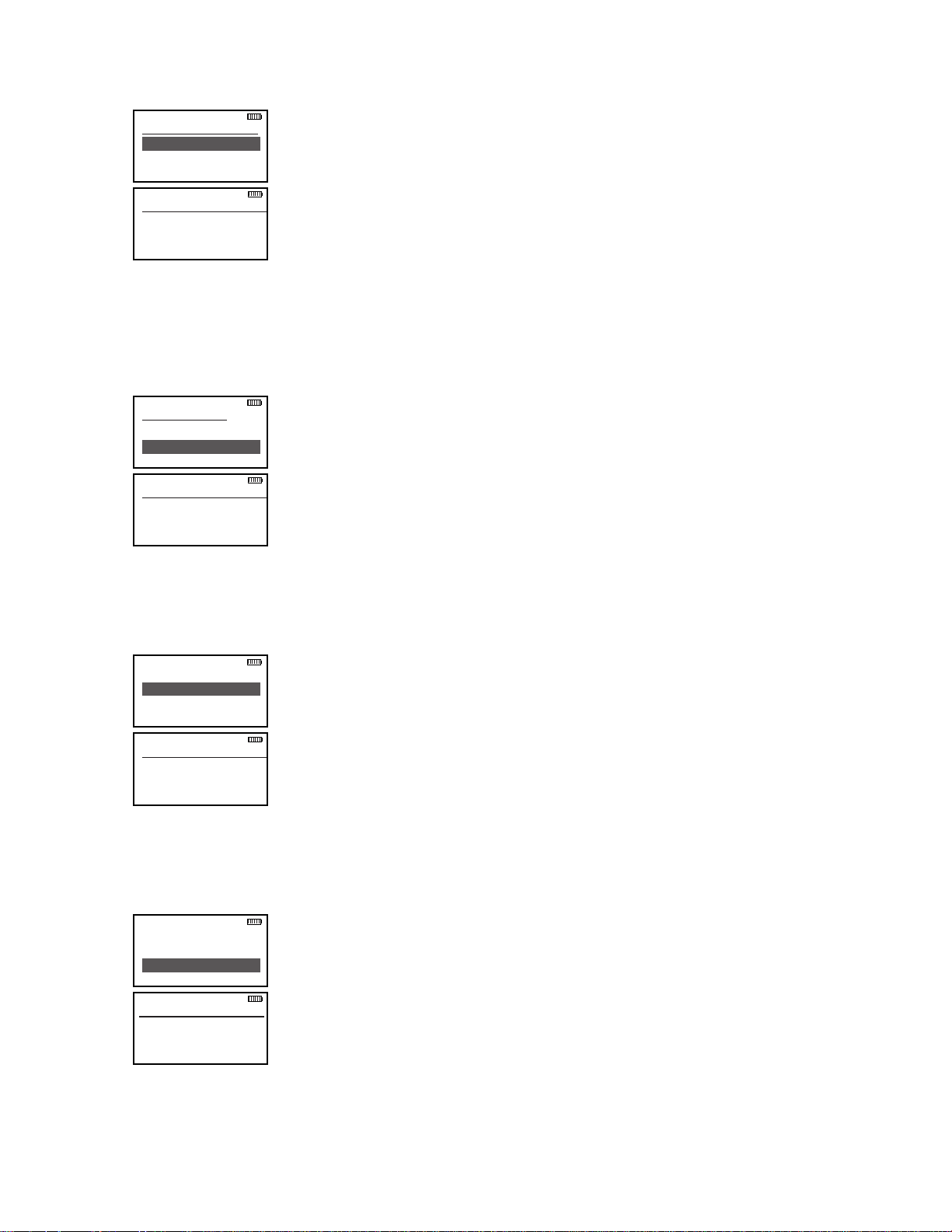
2.2.1.2 proGramminG uSer SelectaBle tranSmit toneS
The KNG can be pre-programmed with up to 32, user selectable, CTCSS or CDCSS subaudible transmit
tones. Tones are selected with the programmed buttons. If enabled, the tones can be programmed via
the radio’s keypad.
to enter tone list programming:
1. Press the Menu button.
2. Use the up/down buttons to highlight ‘Keypad Prog’.
3. Press ‘ENT’.
4. Use the up/down buttons to highlight ‘User Tones’.
5. Press ‘ENT’.
6. Use the keypad to enter the six digit password.
7. Press ‘ENT’.
8. Use the up/down buttons to highlight the User Tone you wish to edit.
9. Press ‘ENT’.
10. Press the ‘CLR’ button to clear the currently programmed tone.
11. To enter CTCSS tones use the keypad to enter the tone in Hertz.
(67.0 - 255 Hz)
To enter CDCSS tones press the # key then enter the three digit code.
(000 - 777)
12. Press the ‘ENT’ button to set the tone.
Page 2-4 Service Manual - KNG Portables
installation and programming
Enter Password
000000
eSc clr ent
Call List
User Tones
User NACs
ESC ▲ ▼ ENT
User NACs
1 - $293
2 - $D7E
ESC ▲ ▼ ENT
NAC 01
$000
eSc clr ent
NA C 01
$
eSc Bck clr ent
Ch 1
KNG - P25
171.5850 0 MHz
liGt t/a menu lck
rxd Scn
Talkaround
Tx Power
Keypad Prog
ESC ▲ ▼ ENT
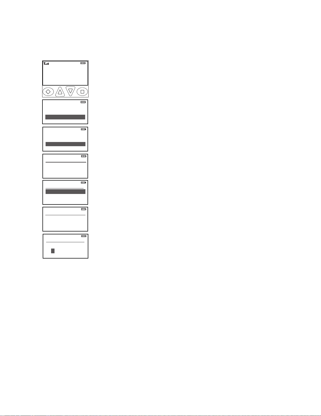
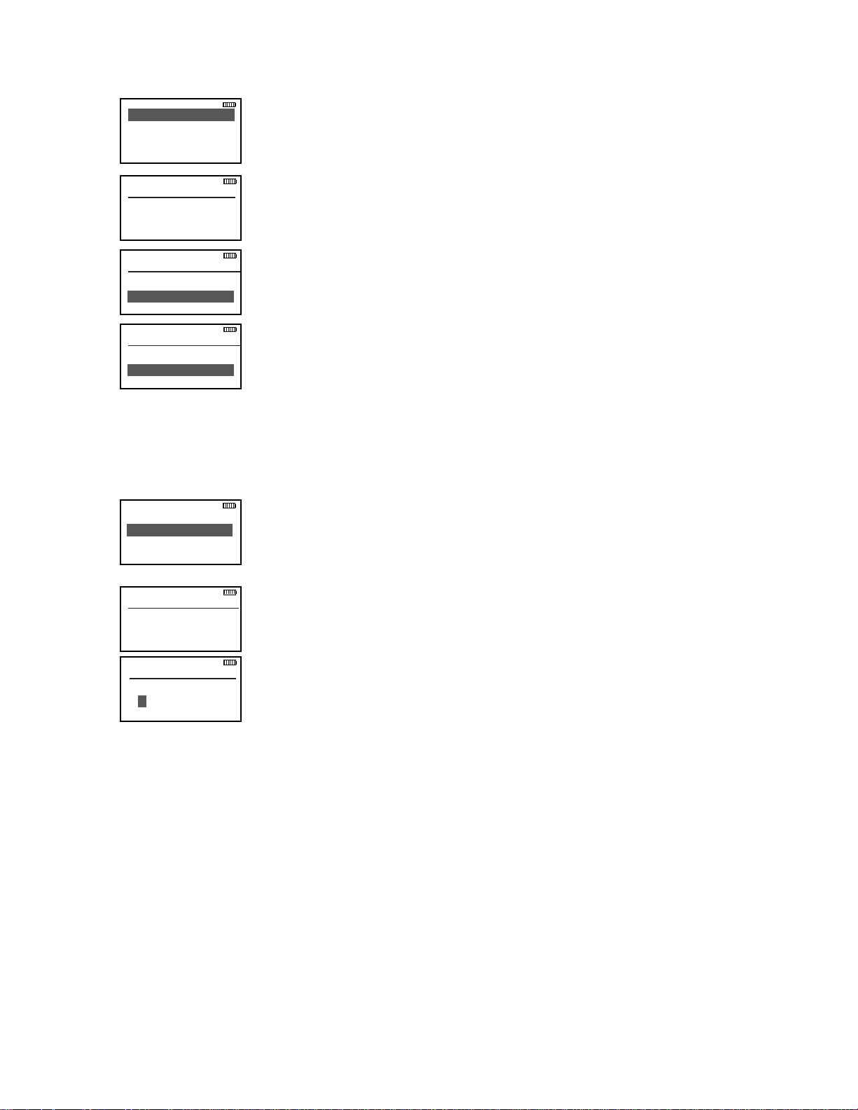
2.2.1.3 proGramminG uSer SelectaBle network acceSS codeS
The KNG can be pre-programmed with up to 32, user selectable NACs. NACS are selected with the
programmed buttons. If enabled, the NACs can be programmed via the radio’s keypad.
to enter nac list programming:
1. Press the Menu button.
2. Use the up/down buttons to highlight ‘Keypad Prog’.
3. Press ‘ENT’.
4. Use the up/down buttons to highlight ‘User NACs’.
5. Press ‘ENT’.
6. Use the keypad to enter the six digit password.
7. Press ‘ENT’.
8. Use the up/down buttons to highlight the NAC you wish to edit.
9. Press the’ ENT’ Button.
10. Press the ‘CLR’ button to clear the currently programmed NAC.
11. NACs are programmed as three digit hexadecimal numbers. (000 - FFF)
Use the keypad to select the desired digits.
Use the 2 key to select A, B or C and the 3 key to select D, E or F.
Press the ‘BCK’ button to move to the previous character.
13. Press the ‘ENT’ button to set the NAC.
BK Radio Page 2-5

installation and programming
Ch 1
KNG - P25
171.5850 0 MHz
liGt t/a menu lck
rxd Scn
Talkaround
Tx Power
Keypad Prog
ESC ▲ ▼ ENT
Enter Password
000000
eSc clr ent
Call List
User Tones
User TGIDs
ESC ▲ ▼ ENT
User TGIDs
1 - 45678
2 - 12345
ESC ▲ ▼ ENT
TGID 01
12345
eSc clr ent
TGID 01
eSc clr ent
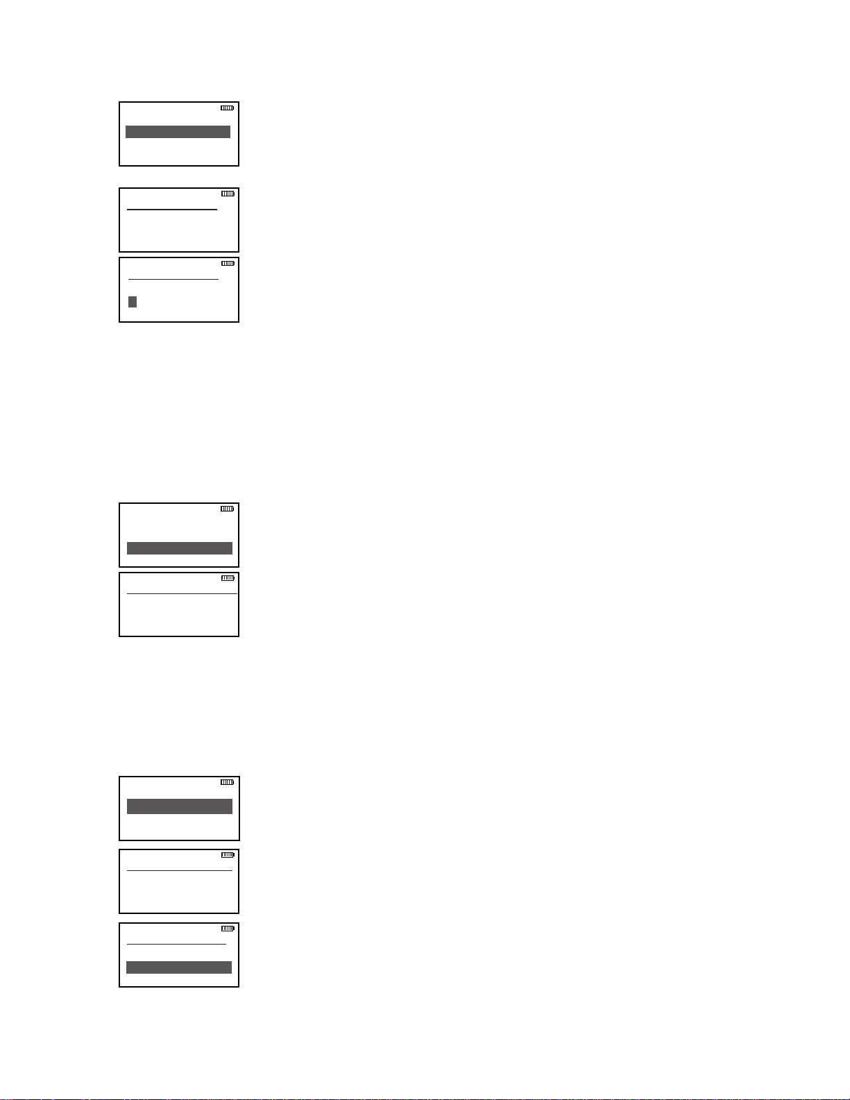
2.2.1.4 proGramminG uSer SelectaBle talkGroup idS
The KNG can be pre-programmed with up to 32, user selectable TGIDs. TDIDs are selected with the
programmed buttons. If enabled, the TGIDs can be programmed via the radio’s keypad.
to enter tGid list programming:
1. Press the Menu button.
2. Use the up/down buttons to highlight Keypad Prog.
3. Press the ‘ENT’ button.
4. Use the up/down buttons to highlight User TGIDs.
5. Press ‘ENT’.
6. Use the keypad to enter the six digit password.
7. Press ‘ENT’.
8. Use the up/down buttons to highlight the TGID you wish to edit.
9. Press the ‘ENT’ Button.
10. Press the ‘CLR’ button to clear the currently programmed TGID.
11. Use the keypad to select the desired Talkgroup number. (0-65355)
13. Press the ‘ENT’ button to set the Talkgroup.
Page 2-6 Service Manual - KNG Portables
installation and programming
Chan Label
Rx Freq
Rx Mode
ESC ▲ ▼ ENT
Enter Password
000000
eSc clr ent
User TGIDs
User Tones
Keypad Prog
ESC ▲ ▼ ENT
Talkaround
Tx Power
Keypad Prog
ESC ▲ ▼ ENT
Channels
Zone Params
Global Params
ESC ▲ ▼ ENT
Select Zone
Zone #
Zone Label
ESC ▲ ▼ ENT
Select Chan
Chan #
Channel Label
ESC ▲ ▼ ENT
Ch 1
KNG - P25
171.5850 0 MHz
liGt t/a menu lck
rxd Scn
2.2.1.5 proGramminG channel parameterS
If enabled, channel, zone and global parameters can be programmed using the radio’s keypad.
Individual parameters may be blocked from programming access. Check with your RELM/BK Radio
dealer or communications ofcer for information on the programmed functions of your radio.
Programmable Channel functions include: Channel Label, Receive Frequency, Receive Mode, Receiver
Code Guard, Squelch Mode, Transmit Frequency, Transmit Mode, Bandwidth, Transmit Code Guard,
Transmit NAC, Talkgroup ID, Secure Mode selection, Encryption Key Lock and Low Power Lock.
to enter the channel programming mode:
1. Press the MENU button.
2. Use the up/down arrows to highlight ‘Keypad Prog’.
3. Press ‘ENT’.
4. Use the up/down arrows to highlight ‘Keypad Prog’.
5. Press ‘ENT’.
6. Use the keypad to enter the six digit password.
7. Press ‘ENT’.
8. Use the up/down arrows to highlight ‘Channels’
9. Press ‘ENT’
8. Use the up/down arrows to select the Zone of the desired channel.
9. Press ‘ENT’.
10. Use the up/down arrows to select the desired channel.
11. Press ‘ENT’.
12. Use the up/down arrows to select the function you wish to edit.
BK Radio Page 2-7
installation and programming
Channel Label
Label
eSc pr1 clr ent
Chan Label
Rx Freq
Rx Mode
ESC ▲ ▼ ENT
eSc Bck clr ent
Channel Label
RX Frequency
151.62500 MHz
eSc clr ent
Chan Label
Rx Freq
Rx Mode
ESC ▲ ▼ ENT
eSc clr ent
RX Frequency
000.00000 MHz
RX Mode
→
Digital
Mixed
ESC ▲ ▼ ENT
Chan Label
Rx Freq
Rx Mode
ESC ▲ ▼ ENT
channel label
1. With ‘Chan Label’ highlighted, press the ‘ENT’ button.
2. Press the ‘CLR’ button to clear the label.
3. Use the keypad to select the desired character.
(See Keypad Character Chart.)
4. Press the ‘BCK’ button to move to the previous character.
Labels can contain up to thirteen characters.
5. Press the ‘ENT’ button to save the label.
6. Press the ‘ESC’ button to return to the Channel Programming menu.
receive frequency
1. With ‘Rx Freq’ highlighted, press the ‘ENT’ button.
2. Press the ‘CLR’ button to clear the current frequency.
3. Use the keypad to select the desired Receive Frequency.
4. Press the ‘ENT’ button to set the frequency.
5. Press the ‘ESC’ button to return to the Channel Programming menu.
receive mode
Page 2-8 Service Manual - KNG Portables
1. With ‘Rx Mode’ highlighted, press the ‘ENT’ button.
2. Use the up/down buttons to highlight the desired Receiver Mode.
(Analog, Digital or Mixed)
3. Press the ‘ENT’ button to set the mode.
4. Press the ‘ESC’ button to return to the Channel Programming menu.

installation and programming
Rx G ua r d
100 .0
eSc clr ent
R x Gu ar d
# for CDCSS
000.0
eSc clr ent
R x Gu ar d
# for CTCSS
D000-
eSc +/- clr ent
Rx Guard
Rx NAC
Squelch Mode
ESC ▲ ▼ ENT
RX NAC
293
eSc clr ent
Rx Guard
Rx NAC
Squelch Mode
ESC ▲ ▼ ENT
eSc Bck clr ent
RX NA C
Squelch Mode
→
Normal
Selective
ESC ▲ ▼ ENT
Rx Guard
Rx NAC
Squelch Mode
ESC ▲ ▼ ENT
receive code Guard
This programs the channels Default Code Guard value.
1. With ‘Rx Guard’ highlighted, press the ‘ENT’ button.
2. Press the ‘CLR’ button to clear the currently programmed tone.
3. To enter CTCSS tones use the keypad to enter the tone in Hertz.
(67.0 - 255 Hz)
To enter CDCSS tones press the # key then enter the three digit code.
(000 - 777) Use the +/- button to invert the CDCSS tone.
4. Press the ‘ENT’ button to set the tone.
5. Press the ‘ESC’ button to return to the Channel Programming menu.
NOTE: If the channel being programmed is currently using a Code Guard from
the Picklist, a “User Picklist Active” notication appear on the display.
receive network access code
Squelch mode
BK Radio Page 2-9
This programs the channels Default NAC value.
1. With ‘Rx NAC’ highlighted, press the ‘ENT’ button.
2. Press the ‘CLR’ button to clear the currently programmed NAC.
3. NACs are programmed as three digit hexadecimal numbers. (000 - FFF)
Use the keypad to select the desired digits.
Use the 2 key to select A, B or C and the 3 key to select D, E or F.
Press the ‘BCK’ button to move to the previous character.
4. Press the ‘ENT’ button to set the NAC.
NOTE: If the channel being programmed is currently using a NAC from the
Picklist, a “User Picklist Active” notication appear on the display.
1. With ‘Squelch Mode’ highlighted, press the ‘ENT’ button.
2. Use the up/down arrows to select Normal or Selective.
(Selective squelch is required for Individual Calls and use of Talkgroup IDs.)
3. Press the ‘ENT’ button to set the selection.
4. Press the ‘ESC’ button to return to the Channel Programming menu.

installation and programming
TX Frequency
151.62500 MHz
eSc clr ent
Squelch Mode
Tx Freq
Tx Mode
ESC ▲ ▼ ENT
eSc clr ent
TX Frequency
000.00000 MHz
TX Mode
→
Digital
Mixed
ESC ▲ ▼ ENT
Squelch Mode
Tx Freq
Tx Mode
ESC ▲ ▼ ENT
TX Mode
→
12.5 kHz
25 kHz
ESC ▲ ▼ ENT
Tx Freq
Tx Mode
Bandwidth
ESC ▲ ▼ ENT
transmit frequency
1. With ‘Tx Freq’ highlighted, press the ‘ENT’ button.
2. Press the ‘CLR’ button to clear the current frequency.
3. Use the keypad to select the desired Receive Frequency.
4. Press the ‘ENT’ button to set the frequency.
5. Press the ‘ESC’ button to return to the Channel Programming menu.
transmit mode
1. With ‘Tx Mode’ highlighted, press the ‘ENT’ button.
2. Use the up/down buttons to highlight the desired Transmit Mode.
(Analog, Digital or Mixed)
3. Press the ‘ENT’ button to set the mode.
4. Press the ‘ESC’ button to return to the Channel Programming menu.
channel Bandwidth
Bandwidth selection applies only to Analog operation.
1. With ‘Bandwidth’ highlighted, press the ‘ENT’ button.
2. Use the up/down buttons to highlight the desired Analog Bandwidth.
(12.5 kHz = narrowband, 25 kHz = wideband)
3. Press the ‘ENT’ button to set the selection.
4. Press the ‘ESC’ button to return to the Channel Programming menu.
Page 2-10 Service Manual - KNG Portables
installation and programming
Tx G uar d
100 .0
eSc clr ent
T x G u ar d
# for CDCSS
000.0
eSc clr ent
T x G u ar d
# for CTCSS
D000-
eSc +/- clr ent
Tx Guard
Tx NAC
TGID
ESC ▲ ▼ ENT
TX NAC
$293
eSc clr ent
Tx Guard
Tx NAC
TGID
ESC ▲ ▼ ENT
eSc Bck clr ent
TX NAC
$
Channel Specic
transmit code Guard
This programs the channels Default Code Guard value.
1. With ‘Tx Guard’ highlighted, press the ‘ENT’ button.
2. Press the ‘CLR’ button to clear the currently programmed tone.
3. To enter CTCSS tones use the keypad to enter the tone in Hertz.
(67.0 - 255 Hz)
To enter CDCSS tones press the # key then enter the three digit code.
(000 - 777) Use the +/- button to invert the CDCSS tone.
4. Press the ‘ENT’ button to set the tone.
5. Press the ‘ESC’ button to return to the Channel Programming menu.
NOTE: If the channel being programmed is currently using a Code Guard from
the Picklist, a “User Picklist Active” notication appear on the display.
transmit network access code
This programs the channels Default NAC value.
1. With ‘Tx NAC’ highlighted, press the ‘ENT’ button.
If the channel you are programming is assigned a specic, non-selectable
NAC the assigned value will be displayed.
If the channel is programmed for User Selectable NACs ‘UNAC Enabled’
will be displayed along with the currently selected picklist number.
2. Press the ‘CLR’ button to clear the currently programmed NAC.
Press the ‘#’ key To toggle between “Channel Specic” and “User
Selected” options.
3. NACs are programmed as three digit hexadecimal numbers. (000 - FFF)
Use the keypad to select the desired digits.
Use the 2 key to select A, B or C and the 3 key to select D, E or F.
Press the ‘BCK’ button to move to the previous character.
4. Press the ‘ENT’ button to set the NAC.
NOTE: If the channel being programmed is currently using a NAC from the
Picklist, a “User Picklist Active” notication appear on the display.
BK Radio Page 2-11
installation and programming
TGID
123 4 5
eSc clr ent
Tx NAC
TGID
Secure Mode
ESC ▲ ▼ ENT
eSc Bck clr ent
TGID
Channel Specic
Secure Mode
→
Clear
Secure
ESC ▲ ▼ ENT
Tx NAC
TGID
Secure Mode
ESC ▲ ▼ ENT
Secure Mode
Key
Key Lock
ESC ▲ ▼ ENT
Encryption Key
01
eSc clr ent
TGID 01
01
eSc clr ent
talkgroup id
This programs the channels Default TGID value.
1. With ‘TGID’ highlighted, press the ‘ENT’ button.
2. Press the ‘CLR’ button to clear the currently programmed TGID.
If the channel you are programming is assigned a specic, non-selectable
TGID the assigned value will be displayed.
If the channel is programmed for User Selectable Talk Groups ‘UTGID
Enabled’ will be displayed along with the currently selected picklist
number.
Press the ‘#’ key To toggle between “Channel Specic” and “User
Selected” options.
3. Use the keypad to select the desired Talkgroup number. (0-65355)
4. Press the ‘ENT’ button to set the Talkgroup.
5. Press the ‘ESC’ button to return to the Channel Programming menu.
NOTE: If the channel being programmed is currently using a TGID from the
Picklist, a “User Picklist Active” notication appear on the display.
encryption Secure mode (Encrypted models)
encryption key (Encrypted models)
Encryption keys must loaded with a compatible key ll device. The radio can hold up to 32 AES and/or
DES keys. (See Encryption Operation)
1. With ‘Secure Mode’ highlighted, press the ‘ENT’ button.
2. Use the up/down buttons to highlight the desired Encryption Selection.
clear = channel always transmits unencrypted.
Secure = channel always transmits encrypted.
Selectable = encryption selected via programmed switch or button
3. Press the ‘ENT’ button to set the mode.
4. Press the ‘ESC’ button to return to the Channel Programming menu.
1. With ‘Key’ highlighted, press the ‘ENT’ button.
2. Press the ‘CLR’ button to clear the currently selected encryption key.
3. Use the keypad to select the desired Encryption Key number. (01-32)
4. Press the ‘ENT’ button to set the Encryption Key.
5. Press the ‘ESC’ button to return to the Channel Programming menu.
Page 2-12 Service Manual - KNG Portables
installation and programming
Key Lock
→
Off
On
ESC ▲ ▼ ENT
Secure Mode
Key
Key Lock
ESC ▲ ▼ ENT
Low Pow Lock
→
Off
On
ESC ▲ ▼ ENT
Key
Key Lock
Low Pow Lock
ESC ▲ ▼ ENT
encryption key lock (Encrypted models)
Encryption Keys can be locked to a channel or selected via a programmed button.
1. With ‘Key Lock’ highlighted, press the ‘ENT’ button.
2. Use the up/down buttons to highlight the desired setting.
Off = Selectable Key, On = Locked Key.
3. Press the ‘ENT’ button to set the selection.
4. Press the ‘ESC’ button to return to the Channel Programming menu.
low power lock
Channels with Low Power Lock enabled ignore the Hi/Lo power switch and
operate in Low Power only.
1. With ‘Low Pow Lock’ highlighted, press the ‘ENT’ button.
2. Use the up/down buttons to highlight the desired setting.
Off = Selectable Power, On = Low Power Only.
3. Press the ‘ENT’ button to set the selection.
4. Press the ‘ESC’ button to return to the Channel Programming menu.
BK Radio Page 2-13

installation and programming
Z o ne L a b e l
Pri 1 Chan
Tx on Pri 1
ESC ▲ ▼ ENT
Enter Password
000000
eSc clr ent
Ch 1
KNG - P25
171.5850 0 MHz
liGt t/a menu lck
rxd Scan
User TGIDs
User Tones
Keypad Prog
ESC ▲ ▼ ENT
Talkaround
Tx Power
Keypad Prog
ESC ▲ ▼ ENT
Channels
Zone Params
Global Params
ESC ▲ ▼ ENT
Select Zone
Zone #
Zone Label
ESC ▲ ▼ ENT
Zone Label
Label
eSc clr ent
Zone Label
Pri 1 Chan
Tx in Pri 1
ESC ▲ ▼ ENT
eSc Bck clr ent
Zone Label
2.2.1.6 proGramminG Zone parameterS
Programmable Zone functions include: Zone Label, Priority 1 Channel, Transmit on Priority 1 Channel,
Priority 2 Channel, Automatic-Number- Identication (ANI) settings and Allow/Disallow Cloning.
to enter the Zone programming mode:
1. Press the MENU button.
2. Use the up/down arrows to highlight ‘Keypad Prog’.
3. Press ‘ENT’.
4. Use the up/down arrows to highlight ‘Keypad Prog’.
5. Press ‘ENT’.
6. Use the keypad to enter the six digit password.
7. Press ‘ENT’.
8. Use the up/down arrows to highlight ‘Zone Params’
9. Press ‘ENT’.
8. Use the up/down arrows to select the desired Zone.
9. Press ‘ENT’.
10. Use the up/down arrows to select the function you wish to edit.
Zone label
1. With ‘Zone Label’ highlighted, press the ‘ENT’ button.
2. Press the ‘CLR’ button to clear the label.
3. Use the keypad to select the desired character.
(See Keypad Character Chart.)
4. Press the ‘NXT’ button to move to the next character.
Labels can contain up to thirteen characters.
5. Press the ‘ENT’ button to save the label.
6. Press the ‘ESC’ button to return to the Zone Programming menu.
Page 2-14 Service Manual - KNG Portables
installation and programming
Pri 1 Channel
→
Main
Channel 1
ESC ▲ ▼ ENT
Zone Label
Pri 1 Chan
Tx on Pri 1
ESC ▲ ▼ ENT
Tx on Pri 1
→
Off
On
ESC ▲ ▼ ENT
Zone Label
Pri 1 Chan
Tx on Pri 1
ESC ▲ ▼ ENT
Pri 2 Channel
→
Main
Channel 1
ESC ▲ ▼ ENT
Tx on Pri 1
Pri 2 Chan
ANI Mode
ESC ▲ ▼ ENT
ANI/DTMF Mode
→
Off
DTMF Only
ESC ▲ ▼ ENT
Tx on Pri 1
Pri 2 Chan
ANI Mode
ESC ▲ ▼ ENT
priority 1 channel
1. With ‘Pri 1 Chan’ highlighted, press the ‘ENT’ button.
2. Use the up/down buttons to highlight the desired Priority Channel.
Off = No Zone Priority Channel.
Main = Priority 1 Channel follows channel select knob.
Channel Label = Assign as Priority 1 Channel.
4. Press the ‘ENT’ button to set the selection.
5. Press the ‘ESC’ button to return to the Zone Programming menu.
transmit on priority 1 channel
If enabled, the radio transmits on the Priority 1 Channel when PRI is turned on.
1. With ‘Tx on Pri 1’ highlighted, press the ‘ENT’ button.
2. Use the up/down buttons to highlight the desired setting.
3. Press the ‘ENT’ button to set the selection.
4. Press the ‘ESC’ button to return to the Zone Programming menu.
priority 2 channel
Automatic Number Identication (ANI) Mode
BK Radio Page 2-15
1. With ‘Pri 2 Chan’ highlighted, press the ‘ENT’ button.
2. Use the up/down buttons to highlight the desired Priority Channel.
Off = No Zone Priority Channel.
Main = Priority 2 Channel follows channel select knob.
Channel Label = Assign as Priority 2 Channel.
4. Press the ‘ENT’ button to set the selection.
5. Press the ‘ESC’ button to return to the Zone Programming menu.
1. With ‘ANI Mode’ highlighted, press the ‘ENT’ button.
2. Use the up/down buttons to highlight the desired setting.
Off = No ANI operation.
DTMF Only = Transmit DTMF Tones with keypad.
ANI Only = Send DTMF ANI on PTT.
BOTH = Keypad Tones and manual ANI.
3. Press the ‘ENT’ button to set the selection.
4. Press the ‘ESC’ button to return to the Zone Programming menu.
 Loading...