

Page 1
EMH
Mobile Radio
Owner's Manual
Page 2

TABLE OF CONTENTS
Introduction.................................................................................. 1
Basic Ope ra tio n........................................................................... 2
Code Guard Operation................................................................. 3
EMH Ra di o Co nt r ol s.................................................................... 4
Button Functions......................................................................... 4
Built-in Fe at ur es ......................................................................... 7
Keypad Microphone Operation.................................................... 8
Channel Scan.............................................................................. 10
Priority Scan................................................................................ 11
Busy Channel.............................................................................. 13
Installation.................................................................................... 14
Service......................................................................................... 16
INTRODUCTION
The Bendix/King EMH radio utilizes a microprocessor core allowing
features and performance previously unavailable in a mobile radio. It
features a 38 MHz operating frequency spread, computer
programmability, alphanumeric display, compact size, and built-in
CTCSS/CDCSS. Please take a moment to acquaint yourself with the
information in this manual to assure optimum performance from the radio.
FCC REQUIREMENTS
The EMH radio must be properly licensed by the Federal
Communications Commission prior to use. Your Bendix/King dealer can
assist you in meeting this requirement.
SAFETY PRECAUTIONS
A. Do not operate the transmitter in close proximity to blasting caps.
B. Do not operate the radio in an explosive atmosphere (petroleum fuels,
solvents, dust, etc.).
C. Do not operate the transmitter if a p erson outside t he vehi cle is with in
two feet of the antenna or touching the antenna.
D. Do not install the radio in a closed compartment that contains an LP
gas container or its fittings.
E. The radio must be properly grounded.
F. The equipment must be installed and serviced by a qualified technician.
EMH Owner’s Manual 1
Page 3

BASIC OPERATION
RECEIVE
TURN POWER ON by rotating the OFF-VOL knob clockwise past the Off
detent.
SET VOLUME by pressing the MON button to hear squelch noise. Rotate
the OFF-VOL knob to set a comfortable volume level. Press the MON
button again to stop squelch noise.
SELECT A CHANNEL GROUP (if applicable) by pressing the GRP button and
rotating the Channel Select knob. Press the GRP button again to view the
group label (alphanumeric mode). Press the GRP button one more time or
allow to time out to return to channel select mode. See "GRP" on page 6.
SELECT A CHANNEL by rotating the Channel Select knob. After reaching
the highest channel number, the radio wraps to channel 1.
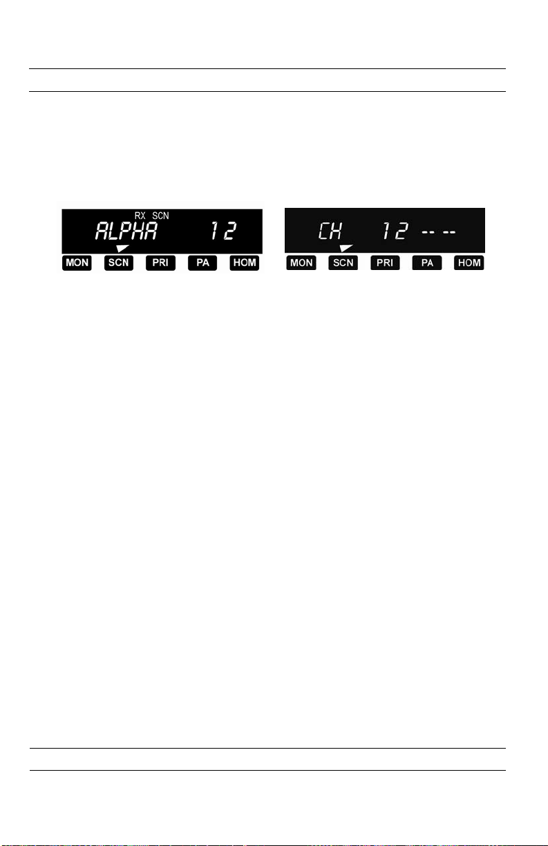
THE ALPHANUMERIC DISPLAY shows either channel numbers (numeric mode)
or channel labels (alphanumeric mode). The display mode and channel
labels are programmed by the technician along with group labels (if
applicable) and channel frequencies. The display shows slightly different
indications during Channel Scan and Priority Scan operation in
alphanumeric and numeric modes. See the illustrations on pages 10 and
11.
TRANSMIT
PRESS THE PTT (Push To Talk) switch on the microphone. The TX
annunciator appears on the display and the red Transmit Indicator glows
while the PTT switch is pressed. Talk in a normal voice with the microphone
approximately 1 to 2 inches from your mouth. Release the PTT s witc h to
stop transmitting.
If the TX annunciator does not appear and a tone is heard, you are on a
receive-only channel or the channel is busy (only if Busy Channel Lockout
is installed). Turn the Channel Select knob to an authorized transmit
channel or wait until the channel is clear (if Busy Channel Lockout is
installed).
If the length of your message exceeds the preset time out timer
setting, the Transmitter automatically shuts off and a tone is heard. To
continue the transmission, release the PTT switch, then press it again and
continue talking.
2 RELM/BK Radio
Page 4

CODE GUARD™ OPERATION
Code Guard™ allows one radio or group of radios to be selectively called
within a system. If your radio has been programmed with Code Gu a r d , u s e t h e
following receive and transmit instructions. Also see "CG" on page 6.
CODE GUARD RECEIVE
TURN POWER ON by rotating the OFF-VOL knob clockwise past the Off detent.
SET VOLUME by pressing the MON button to hear squelch noise. Rotate the
OFF-VOL knob to set a comfortable volume level. Press the MON button
again to stop squelch noise.
SELECT A CHANNEL GROUP (if applicable) by pressing the GRP button and
rotating the Channel Select knob. Press the GRP button again to return to
channel select mode. See "GRP" on page 6.
SELECT A CHANNEL by rotating the Channel Select knob. After reaching the
highest channel number, the radio wraps to channel 1.
PRESS THE CG BUTTON to disable or enable Code Guard operat ion. An arrow on
the display points to the CG button when Code Guard is disabled. When
Code Guard is enabled, a message is heard only when the proper Code
Guard is received.
CODE GUARD TRANSMIT
MONITOR THE CHANNEL, before transmitting on Code Guard channels, by lifting
the microphone off hook or pressing the MON button. Listen to th e c ha nnel for
a few seconds to ensure that no communications are occurring on the
channel.
PRESS THE PTT (Push To Talk) switch on the microphone. Talk in a normal
voice with the microphone approximately 1 to 2 inches from your mouth.
Release the PTT switch to stop transmitting.
HANG UP THE MICROPHONE when finished. If you pressed the MON button to
monitor the channel, press it again after the transmission to return to Code
Guard operation.
Code Guard is a trademark of BK Radio, Inc.
EMH Owner’s Manual 3
Page 5
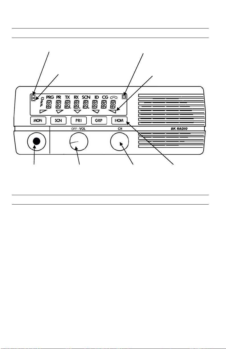
EMH RADIO CONTROLS
y
r
On/O
cators
Transmit Indicator
Priority Indicator
Bus
Channel Indicato
Microphone
Connector
On/Off
Volume Knob
BUTTON FUNCTIONS
Channel
Select
Knob
Display Dimming Sensor
Function Button
ff Indi
Function
Buttons
When the radio is installed, labels are placed on the front push buttons to indicate
their functions. An arrow on the display points to each button that is active.
The buttons can be progra mmed with the following functions:
Monitor Squelch Noise
MON
Channel Scan
SCN
Priority Scan
PRI
Public Address
PA
Group Select
GRP
TA
CG
HOM
SPK
NXT
ACC
Repeater Talk Around
Code Guard Disable
Home Channel
Remote Speaker
Next Scan Channel
Accessory
Transmit Indicator
Each of these controls is described in the following sections.
4 RELM/BK Radio
Page 6

[MON] Monitor Squelch Noise
Press the MON button to start or stop monitoring squelch noise. This allows
you to set a comfortable volume level.
[SCN] Channel Scan
Press the SCN button to start or stop scanning channels in the scan list.
Channel Scan operation occurs only during receive operation. To add or
delete the current channel from the scan list, press the SCN button and hold
it down for 1 second or more. See "Channel Scan" on page 10.
[PRI] Priority Scan
Press the PRI button to start or stop priority scanning. Priority Scan operation
occurs only during receive operation. The PR annunciator, and either the
flashing SCN annunciator (alphanumeric mode) or two flashing bars
(numeric mode) appear on the display. To make the current channel the
fixed priority channel, press the PRI button and hold it for 1 secon d or more.
See "Priority Scan" on page 11.
[PA] Public Address
Press th e PA b u t to n t o t u r n t h e P u b l ic A d d r e s s sy s t e m o n o r o f f . When PA
is on, pressing the microphone PTT switch causes audio to be routed to the
audio amplifier without enabling the transmitter.
[HOM] Home Channel
Press the HOM button to go directly to the pre-programmed home channel.
To set a different Home Channel, select the desired channel using the Channel
Select knob, press the HOM button, and hold it for more than 1 s ec ond until
the arrow above the HOM button appears on the display. The new
channel then becomes the Home Channel.
EMH Owner’s Manual 5
Page 7

[ TA ] Repeater Talk Around
Press the TA button to turn Repeater Talk Around on or off. When TA is on, the
radio transmits on the receive frequency of the selected channel, bypassing
or " ta lki ng a ro und " t he r ep eat er . Th is fun cti on may be used on any channel
that is programmed to a frequency pair (repeater channel).
[NXT] Next Scan List Channel
Press the NXT button to select the next consecutive channel in the scan list
(not during scan operation). During Scan operation, press the NXT button to
select the most recent active channel.
[GRP] Channel Group
Press the GRP button to toggle between group select and channel select
modes. This is used only if the radio has been programmed to divide the
available channels into groups.
Press the GRP button for group select mode. Turn the Channel Select kno b t o
select a group. Return to channel select mode by waiting 5 seconds or by
pressing the GRP button one time (numeric mode) or two times (alphanumeric
mode). After selecting a group in alphanumeric mode, press the GRP button one
time to display the group label and a sec ond ti me to ret urn to ch ann el sel ect
mode.
[ACC] Accessory
Press the ACC button to turn the installed accessory on or off.
[SPK] Speaker
Press the SPK button to switch betw een the built-in ra dio speaker and an
optional remote speaker.
[CG] Code Guard Disable
Press the CG button to disable or enable Code Guard operation. An arro w on
the display points to the CG button when Code Guard is disabled. When
Code Guard is enabled, a message is heard only when the proper Code
Gua rd i s rec eive d. Tr ansm it C ode G uard generation is unaffected. The CG
button m a y also b e used t o overr i d e Busy Channel Lockout, if that is installed.
See "Busy Channel Lockout Ove r r i d e" o n page 13.
6 RELM/BK Radio
Page 8

BUILT-IN FEATURES
Bendix/King EMH radios are based on a microprocessor core that allows
extra features and operational characteristics to be built into the radio. Your
dealer will help define the best operational settings for your system and
program them into the radio.
ADDITIONAL FREQUENCIES
Additional transmit and receive frequencies can be added. If you wish to monitor
other local radio systems that fall anywhere in your band, a frequency with or
without Code Guard can be added to your program.
TIME OUT TIMER
The time out timer limits the duration of calls and guards against
accidentally locking on the transmitter and tying up the radio system. The
duration of the time out timer can be changed by your dealer. (15-225 seconds,
or 0 - disabled)
DTMF/ANI
A DTMF/ANI encoding feature is also available. If ANI is enabled by your
dealer, a sequence of DTMF tones (similar to the tones used by a standard
pushbutton telephone) are transmitted each time the transmit PTT switch
is activated. When DTMF is enabled, DTMF tones are transmitted when
keys are pressed on the optional keypad microphone.
SCAN DELAY
Scan delay allows the radio to receive a response to a transmission before
scanning the other channels for activity. If you find that your scanner is
restarting before message replies are heard, you can ask your dealer to
increase the scan delay time. (0-7.5 seconds)
EMH Owner’s Manual 7
Page 9

KEYPAD MICROPHONE OPERATION
If a keypad microphone is used with the EMH radio, the following f eatures
may be enabled. Not all microphones support these functions. Contact
your dealer to determine which features are available with your microphone
and have been enabled in the radio.
GROUP SELECTION
Select a channel group by pressing the # key on the keypad microphone
followed by the number of the desired group. This is used only if the radio has
been programmed to divide the available ch annels into groups.
DTMF ENCODE
DTMF Encode (telephone touch tone) is accomplished by pressing and
holding the keypad microphone PTT switch, and then pressing the 0 - 9 keys
for the encoding operation desired. After the desired numbers have been
entered, monitor or transmit as required.
ANI OPERATION
Automatic Number Identification can be programmed into the EMH radiofor
use with inter-connect telephone and other systems requiring user s t o i dentify
before allowing use of the system.
USER SELECTED SCAN LIST
Press the ENT button on the keypad microphone to add the selected channel to
the scan list. The SCN annunciator appears on the display for each channel
entered in the scan list. Press the CLR button on the keypad microphone to
remove (clear) the selected channel from the scan list. This can be
accomplished during Channel Scan operation to remove an unwanted
channel.
8 RELM/BK Radio
Page 10

USER SELECT PRIORITY CHANNEL
Press the PRI button on the keypad microphone to make the current
channel the fixed priority channel. The PR annunciator appears on the
display. This occurs in priority scan modes B, C, and D, but not A. See
"Priority Scan" on page 11.
USER SELECTED CODE GUARD
When the frequencies are programmed for each channel in the radio, a
receive Code Guard value and a transmit Code Guard value may also be
entered for each channel. The Code Guard values for channels 1 -9 can be
used for another channel in the radio. For example, to use the Code Guard
values of Channel 9 with the frequencies of Channel 5:
1. Turn off the SCN and PRI buttons.
2. Set the Channel Selector knob to Channel 5.
3. Press the 9 key on the keypad microphone. The CG annunciator
appears on the display to indicate that the Code Guard has been
changed from its original programming.
4. Press the 0 key to reset all values to the original settings, or press
a different number key to select a different set of Code Guard
values.
In numeric mode, the display shows the selected c hannel (Ch 5) wit h
the Code Guard value channel (9) to the right. The CG annunciator
appears on the display to indicate that the Code Guard has been
changed from its original programming.
In alphanumeric mode, the display shows the label for the Code Guard
value channel (ALPHA 9) briefly when changing to Channel 5, th e n t he
display shows the label for the selected channel (ALPHA 5). The
CG annunciator appears on the display to indicate that the Code
Guard has been changed from its original programming.
EMH Owner’s Manual 9
Page 11
CHANNELSCAN
Press the SCN button to start or stop scanning channels in the scan list . Sca n
operation occurs only while the radio is not transmitting. Scan operation is
indicated on the display by the flashing SCN annunciator (alphanumeric
mode) or two flashing bars (numeric mode) .
The radio scans all channels in the scan list for activity. When activity is detected,
the radio receives the active channel, and the channel name or number
appears on the display.
Channels in the scan list are pre-programmed. To determine which channels
are in the scan list, select a channel with the channel knob. If it is in the scan list
the SCN annunciator appears in the display.
To add or delete the current channel from the scan li st, pres s the S CN button and
hold it down for 1 second or more. A beep sounds when the scan list change is
executed.
PRIORITYSCAN
10 RELM/BK Radio
Page 12
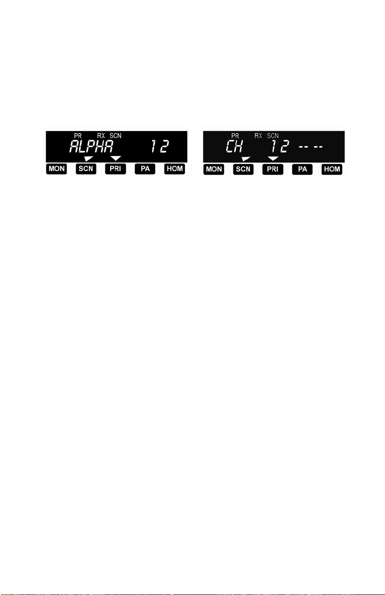
Press the PRI button to start or stop priority scanning. Priority scan operation
occurs only during receive operation. Priority scan operation is indicated on the
display by the PR annunciator and either the flashing SCN annunciator
(alphanumeric mode) or two flashing bars (nu me ric mo de) .
To make the current channel the fixed priority channel, press the PRI button and
hold it for 1 second or more. A beep sounds and the PR annunciator appears
when the priority channel change is executed. This occ urs in pri ority scan
modes B, C, and D, but not A.
The EMH radio can be programmed with one of four priority scan modes:
A, B, C, and D.
PRIORITY MODE A
The channel selected with the Channel Select knob becomes the priority
channel as well. When scanning with the PRI button on, the receiver checks
the priority channel for activity. If activity is detected by scanning and the
receiver stops on a channel other than the priority channel, the receiver
continues to check the priority channel for activity. If, in this condition, activity
is detected on the priority channel, the radio receives the priority channel
activity for the duration of the transmission, then returns to scanning operation.
The yellow Priority Indicator glows during the priority reception. The radio
transmits on the channel selected with the Channel Select knob.
EMH Owner’s Manual 11
Page 13

PRIORITY MODE B
In priority mode B the priority mode is fixed in programming and
indicated by the PR annunciator when the priority channel is selected. Priority
operation during scanning is the same as with Priority mode A, except that
the priority channel is pre-programmed, not the selected channel.
However, with any channel selected other than the fixed priority channel w i th
SCN off and PRI on, the receiver checks the priorit y channel while receiving
on the selected channel. If activity is detected on the priority channel, the
receiver switches to receive the priority channel for the duration of the
transmission, then returns to the selected channel. The radio transmits on
the knob-selected channel while operating in priority mode B.
PRIORITY MODE C
In priority mode C the priority channe l is pre-programmed. This channel
is displayed anytime PRI is on, no matter where the Channel Select knob is
set. Priority operation during scan operation is the same as with Priority
Mode A, except that the priority channel is preprogrammed, not the
sele cte d ch anne l. I n pr iori ty m ode C the transmitter always transmits on
the priority channel when PRI is on.
PRIORITY MODE D
Priority mode D operates exactly like pr iority mo de C . Howe ver wh en PR I i s
on, the channel name or number displayed is the knob-selected ch annel,
not the fixed priority channel.
12 RELM/BK Radio
Page 14

BUSY CHANNEL
If your radio has been programmed by your dealer for busy channel operation,
it will operate in one of the following three modes.
BUSY CHANNEL INDICATION
The yellow Busy Channel Indicator glows if there is carrier activity on the
channel selected. If the channel selected is a Code Guard channel and the
correct code is not detected, the Busy Channel Indicator remains on for the
duration of the carrier activity and no messages are heard. During Channel
Scan and Priority Scan operation, the Busy Channel Indicator glows when
activity is detected on any channel that is on the scan list. When scanning Code
Guard channels, with the CG button on, and activity has been detected, the Busy
Channel Indicator glows for the time period necessary to determine if the
prop er C ode Guard has been received, causing the Busy Channel Indicator to
flash at various rates. In Priority Scan operation, with the CG button on, the Busy
Channel Indicator remains on for the duration of the carrier activity .
BUSY CHANNEL LOCKOUT
The Busy Channel Lockout feature applies only to those channels
programmed for receive Code Guard operation. When carrier activity is
detected on the channel selected, the radio checks the receive Code Guard
value. If the proper Code Guard value is present, the radio can t r an s m it on t ha t
channel, e ven if the CG b utton is not on. If the radio detects an incorrect value
or carrier activity only, the transmitter is disabled, an a lert tone is he ard, and
the disp lay s hows the w ord "Busy" whe n the PTT is pressed, regardless of
whether the CG button is on or off.
Channels not programmed for receive Code Guard operation transmit
regardless of carrier activity.
BUSYCHANNEL LOCKOUT OVERRIDE
This mode operates in the same manner as Busy Channel Lockout with the
exception that the user can override and transmit by pressing the CG button.
EMH Owner’s Manual 13
Page 15

INSTALLATION
Plan your installation carefully. Locate the radio and microphone within easy
reach, giving the operator a clear view the display. Do not loc ate th e radi o or
microphone in a position that interferes with safe operation of the vehicle.
Once the equipment location is chosen, determine the best routing for cables
and wires to connect the system. Use a rubber grommet to protect th e wi res
when passing through sheet metal. Avoid any route that subjects the wire to
pinching, cutt ing, o r high he at from t he engine or other vehicle component.
The radio must be used with a 12 volt, NEGATIVE GROUND electrical system.
1 . Crimp the fuse holder in line with the red power lead as close to the
battery as possible.
2. Connect the red power lead to the vehicle battery POSITIVE terminal.
Using other positive voltage points in the vehi cle is not recommend ed.
3. Connect the black lead to a good ground point on the vehicle chassis.
Connection to the negative battery terminal is not recommended.
4. Mount the antenna carefully. Follow the instructions supplied with the
antenna kit. Route the coax cable to the radio mounting lo cation.
5 . Fasten the mounting bracket securely to the d esired lo cation.
6. Mount the microphone clip securely to the desired location. The
microphone hanger clip must be grounded for proper radio operation.
Use the ground wire (item 13) if needed.
7. Mount any approved accessory speakers and route the wires to the
rear of the radio bracket.
8 . Connect the power lead antenna connector, and accessory wires to
the rear of the radio.
9. Place the radio in the mounting bracket, adjust to the proper mounting
angle, and thread in the two side mounting knobs until the unit is
secure.
NOTE: Option A and B connections are logic level outputs. Consult your BK
Radio dealer before connecting accessories to these pins.
14 RELM/BK Radio
Page 16

SERVICE
If you need service, contact your Bendix/King dealer or any other
Bendix/King dealer equipped to service your radio. If you find it
impractical to have service performed by your local dealer, contact BK Radio
at the address below:
RELM Wireless Corporation
7100 Technology Drive
West Melbourne, FL 32904
(800) 422-6281
Fax:(321)953-7986
EMH Owner’s Manual 15
 Loading...