

Page 1
Page 2
Safety Summary
The following safety precautions apply to both operating and maintenance personnel and must be followed during all
phases of operation, service, and repair of this instrument.
Before applying power to this instrument:
• Read and understand the safety and operational information in this manual.
• Apply all the listed safety precautions.
• Verify that the voltage selector at the line power cord input is set to the correct line voltage. Operating the instrument
at an incorrect line voltage will void the warranty.
• Make all connections to the instrument before applying power.
• Do not operate the instrument in ways not specied by this manual or by B&K Precision.
Failure to comply with these precautions or with warnings elsewhere in this manual violates the safety standards of design,
manufacture, and intended use of the instrument. B&K Precision assumes no liability for a customer’s failure to comply
with these requirements.
2
Category rating
The IEC 61010 standard denes safety category ratings that specify the amount of electrical energy available and the
voltage impulses that may occur on electrical conductors associated with these category ratings. The category rating is
a Roman numeral of I, II, III, or IV. This rating is also accompanied by a maximum voltage of the circuit to be tested,
which denes the voltage impulses expected and required insulation clearances. These categories are:
Category I (CAT I): Measurement instruments whose measurement inputs are not intended to be connected to the
mains supply. The voltages in the environment are typically derived from a limited-energy transformer or a battery.
Category II (CAT II): Measurement instruments whose measurement inputs are meant to be connected to the mains
supply at a standard wall outlet or similar sources. Example measurement environments are portable
tools and household appliances.
Category III (CAT III): Measurement instruments whose measurement inputs are meant to be connected to the mains
installation of a building. Examples are measurements inside a building’s circuit breaker panel
or the wiring of permanently-installed motors.
Category IV (CAT IV): Measurement instruments whose measurement inputs are meant to be connected to the primary
power entering a building or other outdoor wiring.
Do not use this instrument in an electrical environment with a higher category rating than what is specied in this manual
for this instrument.
You must ensure that each accessory you use with this instrument has a category rating equal to or higher than the
instrument’s category rating to maintain the instrument’s category rating. Failure to do so will lower the category rating
of the measuring system.
Page 3
Electrical Power
This instrument is intended to be powered from a CATEGORY II mains power environment. The mains power should be
115 V RMS or 230 V RMS. Use only the power cord supplied with the instrument and ensure it is appropriate for your
country of use.
Ground the Instrument
To minimize shock hazard, the instrument chassis and cabinet must be connected to an electrical safety ground. This
instrument is grounded through the ground conductor of the supplied, three-conductor AC line power cable. The power
cable must be plugged into an approved three-conductor electrical outlet. The power jack and mating plug of the power
cable meet IEC safety standards.
Do not alter or defeat the ground connection. Without the safety ground connection, all accessible conductive parts
(including control knobs) may provide an electric shock. Failure to use a properly-grounded approved outlet and the
recommended three-conductor AC line power cable may result in injury or death.
3
Unless otherwise stated, a ground connection on the instrument’s front or rear panel is for a reference of potential only
and is not to be used as a safety ground. Do not operate in an explosive or ammable atmosphere.
Do not operate the instrument in the presence of ammable gases or vapors, fumes, or nely-divided particulates.
The instrument is designed to be used in oce-type indoor environments. Do not operate the instrument
• In the presence of noxious, corrosive, or ammable fumes, gases, vapors, chemicals, or nely-divided particulates.
• In relative humidity conditions outside the instrument’s specications.
• In environments where there is a danger of any liquid being spilled on the instrument or where any liquid can condense
on the instrument.
• In air temperatures exceeding the specied operating temperatures.
• In atmospheric pressures outside the specied altitude limits or where the surrounding gas is not air.
• In environments with restricted cooling air ow, even if the air temperatures are within specications.
• In direct sunlight.
This instrument is intended to be used in an indoor pollution degree 2 environment. The operating temperature range is
0∘C to 40∘C and 20% to 80% relative humidity, with no condensation allowed. Measurements made by this instrument
may be outside specications if the instrument is used in non-oce-type environments. Such environments may include
rapid temperature or humidity changes, sunlight, vibration and/or mechanical shocks, acoustic noise, electrical noise,
strong electric elds, or strong magnetic elds.
Page 4
Do not operate instrument if damaged
If the instrument is damaged, appears to be damaged, or if any liquid, chemical, or other material gets on or inside the
instrument, remove the instrument’s power cord, remove the instrument from service, label it as not to be operated,
and return the instrument to B&K Precision for repair. Notify B&K Precision of the nature of any contamination of the
instrument.
Clean the instrument only as instructed
Do not clean the instrument, its switches, or its terminals with contact cleaners, abrasives, lubricants, solvents, acids/bases,
or other such chemicals. Clean the instrument only with a clean dry lint-free cloth or as instructed in this manual. Not
for critical applications
This instrument is not authorized for use in contact with the human body or for use as a component in a life-support
device or system.
4
Do not touch live circuits
Instrument covers must not be removed by operating personnel. Component replacement and internal adjustments must
be made by qualied service-trained maintenance personnel who are aware of the hazards involved when the instrument’s
covers and shields are removed. Under certain conditions, even with the power cord removed, dangerous voltages may
exist when the covers are removed. To avoid injuries, always disconnect the power cord from the instrument, disconnect
all other connections (for example, test leads, computer interface cables, etc.), discharge all circuits, and verify there
are no hazardous voltages present on any conductors by measurements with a properly-operating voltage-sensing device
before touching any internal parts. Verify the voltage-sensing device is working properly before and after making the
measurements by testing with known-operating voltage sources and test for both DC and AC voltages. Do not attempt
any service or adjustment unless another person capable of rendering rst aid and resuscitation is present.
Do not insert any object into an instrument’s ventilation openings or other openings.
Hazardous voltages may be present in unexpected locations in circuitry being tested when a fault condition in the circuit
exists.
Fuse replacement must be done by qualied service-trained maintenance personnel who are aware of the instrument’s fuse
requirements and safe replacement procedures. Disconnect the instrument from the power line before replacing fuses.
Replace fuses only with new fuses of the fuse types, voltage ratings, and current ratings specied in this manual or on
the back of the instrument. Failure to do so may damage the instrument, lead to a safety hazard, or cause a re. Failure
to use the specied fuses will void the warranty.
Page 5

Servicing
Do not substitute parts that are not approved by B&K Precision or modify this instrument. Return the instrument to
B&K Precision for service and repair to ensure that safety and performance features are maintained.
For continued safe use of the instrument
• Do not place heavy objects on the instrument.
• Do not obstruct cooling air ow to the instrument.
• Do not place a hot soldering iron on the instrument.
• Do not pull the instrument with the power cord, connected probe, or connected test lead.
• Do not move the instrument when a probe is connected to a circuit being tested.
Compliance Statements
5
Complies with the essential requirements of the following applicable European Directives, and carries the CE marking
accordingly:
• Electromagnetic Compatibility (EMC) Directive 2014/30/EU
• Low-Voltage Directive (Safety) 2014/35/EU
Conforms with the following product standards:
EMC Standard
IEC 61326-1:2012/ EN 61326-1:2013
Reference Standards
CISPR 11:2009+A1:2010/ EN 55011:2009+A1:2010 (Group 1, Class A)
IEC 61000-4-2:2008/ EN 61000-4-2:2009
IEC 61000-4-3:2006+A1:2007+A2:2010/ EN 61000-4-3:2006+A1:2008+A2:2010
IEC 61000-4-4:2004+A1:2010/ EN 61000-4-4:2004+A1:2010
IEC 61000-4-5:2005/ EN 61000-4-5:2006
IEC 61000-4-6:2008/ EN 61000-4-6:2009
IEC 61000-4-11:2004/ EN 61000-4-11:2004
1. The product is intended for use in non-residential/non-domestic environments. Use of the product in residential/domestic environments may cause electromagnetic interference.
123
2. Connection of the instrument to a test object may produce radiations beyond the specied limit.
3. Use high-performance shielded interface cable to ensure conformity with the EMC standards listed above.
Safety Standard
IEC 61010-1:2010/ EN 61010-1:2010
Page 6
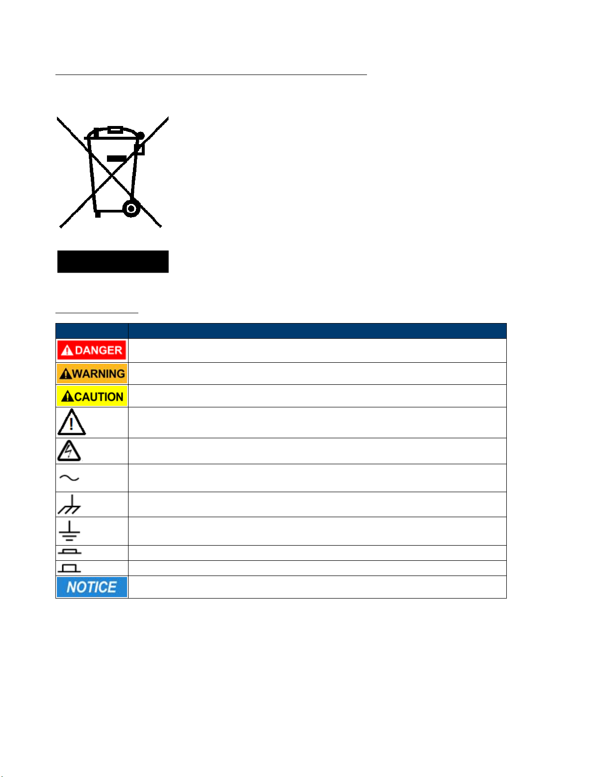
Waste Electrical and Electronic Equipment (WEEE) Directive
Disposal of Old Electrical & Electronic Equipment (Applicable in the European Union and other European
countries with separate collection systems)
This product is subject to Directive 2002/96/EC of the European Parliament
and the Council of the European Union on waste electrical and electronic equipment
(WEEE), and in jurisdictions adopting that Directive, is marked as being put on the
market after August 13, 2005, and should not be disposed of as unsorted municipal
waste. Please utilize your local WEEE collection facilities in the disposition of this
product and otherwise observe all applicable requirements.
Safety Symbols
6
Symbol Description
indicates a hazardous situation which, if not avoided, will result in death or serious injury.
indicates a hazardous situation which, if not avoided, could result in death or serious injury
indicates a hazardous situation which, if not avoided, will result in minor or moderate injury
Refer to the text near the symbol.
Electric Shock hazard
Alternating current (AC)
Chassis ground
Earth ground
This is the In position of the power switch when instrument is ON.
This is the Out position of the power switch when instrument is OFF.
is used to address practices not related to physical injury.
Page 7

Contents
1 Introduction 9
1.1 Product Overview 9
1.2 Description 9
1.3 Features 10
1.4 Dimensions 10
1.5 Front Panel 11
1.6 Rear Panel 12
1.7 Protection Functions 13
1.7.1 Overvoltage Protection (OVP) 13
1.7.2 Operations to Clear the OVP State 13
1.7.3 Overcurrent Protection (OCP) 13
1.7.4 Overpower Protection (OPP) 14
1.7.5 Overtemperature Protection (OTP) 14
1.7.6 Reverse Voltage Protection (LRV/RRV) 15
1.8 Menu List 15
2 Installation 19
2.1 Inspection 19
2.2 Cleaning 19
2.3 Installing Modules 19
2.4 Channel Number 22
2.5 Location 23
2.6 Input Voltage Selection 23
2.7 Turn-On Checkout 24
2.8 If the Electronic Load Does Not Turn On. 24
3 Load Connection 26
3.1 Parallel Connection 27
3.2 Mainframe 8-pin Control Connector 28
3.3 External Trigger Connections 29
3.3.1 Trigger Modes 29
3.4 External ON/OFF Control Connection 30
3.5 Mainframe Extension Connection 30
3.6 PC Control Connection 31
4 Operations 32
4.1 Operation Modes 32
4.1.1 Constant Current (CC) Mode 32
4.1.2 Constant Voltage (CV) Mode 34
4.1.3 Constant Resistance (CR) Mode 35
4.1.4 Constant Power (CP) Mode 36
4.1.5 Constant Impedance (CZ) Mode 37
4.1.5.1 Setting CV,CC,CR, CW,CZ Mode 38
4.2 Local Operations 39
4.2.1 Mainframe Panel 39
4.2.2 Module Panel 41
4.2.3 Module Panel Lock 42
4.3 Switching Channels 42
4.4 Channel Synchronization 42
4.5 Module VFD Indicator Function Description 43
4.6 Transient Operation 44
4.6.1 Continuous 44
4.6.2 Pulse 45
Page 8

4.6.3 Toggle 45
4.6.4 Setting Up A/B Transient Operation 46
4.7 List Operation 48
4.7.1 Setting Up List Operation Mode 48
4.8 Trigger Operation 51
4.8.1 Manual Trigger 51
4.8.2 External Trigger Signal(TTL level) 51
4.8.3 Hold Trigger 51
4.8.4 Bust Trigger 51
4.8.5 Timer Trigger 51
4.9 Short Operation 51
4.10 Input On/O Operation 51
4.11 Von Operation 52
4.12 Save and Recall Operation 54
4.13 Module Controlling Link 54
4.13.1 Voltage Failure Indication 55
4.13.2 Current Monitoring 55
4.13.3 Digital I/O 55
4.13.4 Remote Sense Function 55
4.13.5 External Analog Control 55
4.14 Automatic Test 56
4.15 Conguring Pass/Fail Paramters 56
4.15.1 Conguring Instrument Settings 56
4.15.2 Recall Test Files 59
4.16 Remote Operation 60
4.16.1 USB Interface 61
4.16.2 Ethernet Interface 61
4.16.3 GPIB Interface 61
8
5 Specications 64
6 Service Information 66
7 LIMITED THREE-YEAR WARRANTY 67
Page 9
Introduction
1.1 Product Overview
This section describes the main features and menus of the MDL4U Series DC Electronic Load. The MDL4U Series is
comprised of two parts, mainframes and modules. The mainframes mentioned are the MDL4U001 mainframe and the
MDL4U002 mainframe extension. Modules in this series include the MDL4U200, MDL4U252, MDL4U302, MDL4U305,
MDL4U400, MDL4U505, and MDL4U600. Unless otherwise noted, this document will refer to all of these instruments as
“electronic load”. The range of each module’s specic voltage, current, and power is listed in the
1.2 Description
Specications section.
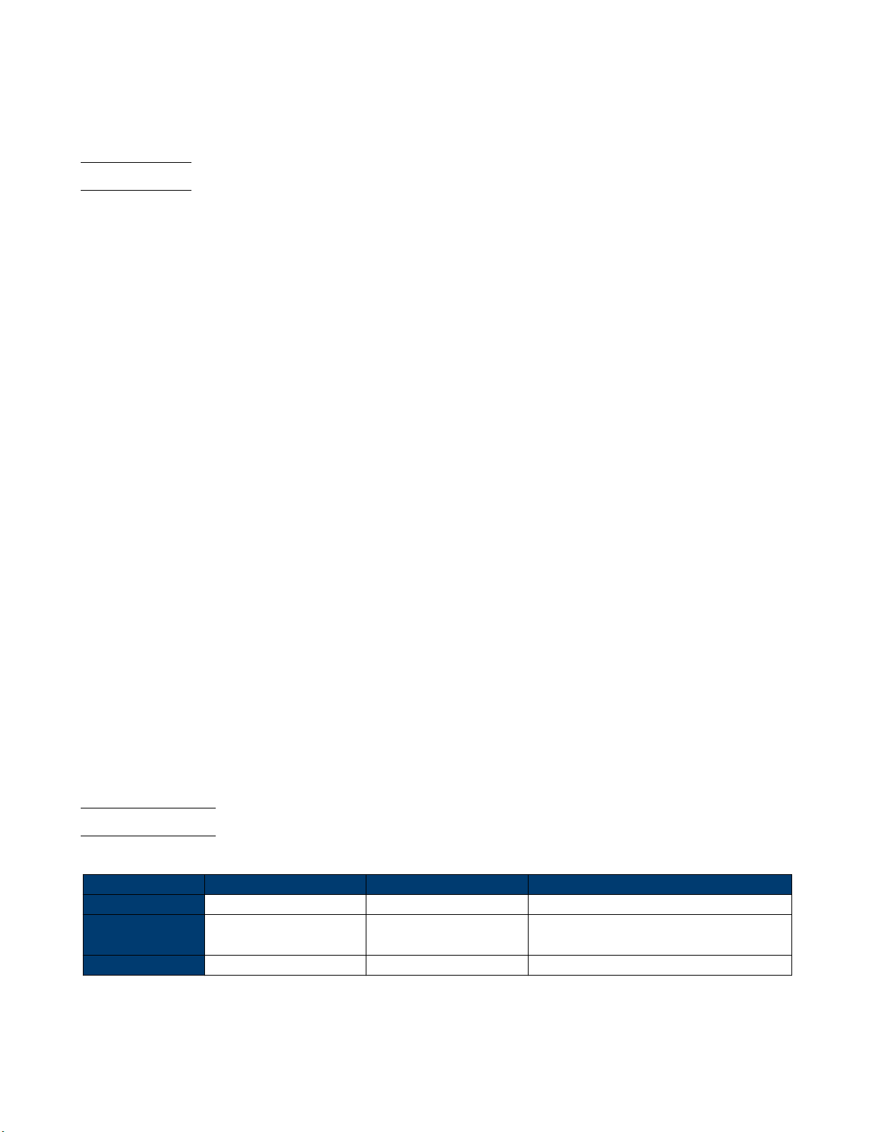
Front View Rear View
Figure 1.1 MDL4U 001 and 002 Populated
The MDL4U Series is a multi-channel modular programmable electronic load system. Seven dierent modules of programmable DC loads ranging in power from 200 W to 600 W provide users the exibility to test a wide range of power
sources from multi-output DC power supplies to batteries, fuel cells, and photovoltaic arrays.
Up to four modules can be installed into the MDL4U001 mainframe to support up to a total of 8 channels. Adding the
MDL4U002 mainframe extension will enable the system to support four additional module slots for a maximum of 16
channels. The electronic load is congured by installing user-selectable modules into the mainframe and operated using
the front panel keypad and rotary knob. It can also be controlled remotely via USB, RS-232, LAN, or GPIB interface.
The electronic load modules all have similar functions, but may dier in range of input voltage, current, and power. The
high resolution voltage and current measurement system provides both accuracy and convenience.
The electronic load can be used in one of ve dierent operation modes: constant voltage (CV), constant current (CC),
constant resistance (CR), constant power (CW), or constant impedance (CZ). All panel operation and programming
functions are carried out on the MDL4U001 mainframe panel. A wide range of dynamic loading applications can be
simulated through user-programmable slew rates, load levels, duration, and conducting voltage.
Model MDL4U200 MDL4U252 MDL4U302 MDL4U305 MDL4U400 MDL4U505 MDL4U600
Power 200 W *250 W/50W *300 W/300 W 300 W 400 W 500 W 600 W
Operating Voltage 80 V 80 V 80 V 500 V 80 V 500 V 80 V
Rated Current 40 A 20 A 45 A 20 A 60 A 30 A 120 A
No. of Channels 1 2 2 1 1 1 1
Table 1.1 MDL4U Modules
Page 10
Introduction 10
* The MDL4U252 and MDL4U302 are dual-channel load modules. The MDL4U252 can allocate up to 250 W to either
channel up to 300 W total. (e.g. 250 W/50 W, 150 W/150 W). Similarly, the MDL4U302 can allocate 300 W to either
channel up to 600 W total (e.g. 300 W/300 W)
1.3 Features
• Power range up to 2400 W
• Voltage range up to 500 V
• Current range up to 120 A
• CC/CV/CR/CW/CZ operating modes
• Removable modules for easy system congurability
• Support for up to 16 channels using dual channel modules with mainframe extension
• Operate identical modules in parallel mode for high current applications
• Synchronous load on/o function
• Standard LAN, GPIB, USB, and RS232 interfaces with USBTMC/SCPI protocol support
• Analog current control and monitoring
• Transient mode up to 25 kHz
• List mode (sequence mode) - minimum 20 s step width with 84 user programmable steps
• Adjustable slew rate in CC mode
• 16-bit voltage and current measurement system providing high resolution of 0.1 mV and 0.01 mA
• Automatic test function
• 101 memory locations to save/recall setting parameters
• Remote sense
• OVP/OCP/OPP/OTP and reverse voltage protection
• Rack-mount brackets with handles included
1.4 Dimensions
The MDL4U’s dimensions are as follow:
MDL4U Model : 001 002 200, 252, 302, 305, 400, 505, 600
Type Mainframe Mainframe extendsion Module
Dimensions
(W x H x D)
Weight 34 lbs (15.4 kg) 34 lbs (15.4 kg) 11 lbs (5 kg)
17.3” x 7” x 21.6”
(440 x 177.3 x 549 mm)
17.3” x 7” x 21.6”
(440 x 177.3 x 549 mm)
3.2” x 6.7” x 22.6”
(82 x 170.5 x 573 mm)
Table 1.2 MDL4U Modules
Page 11
Introduction 11
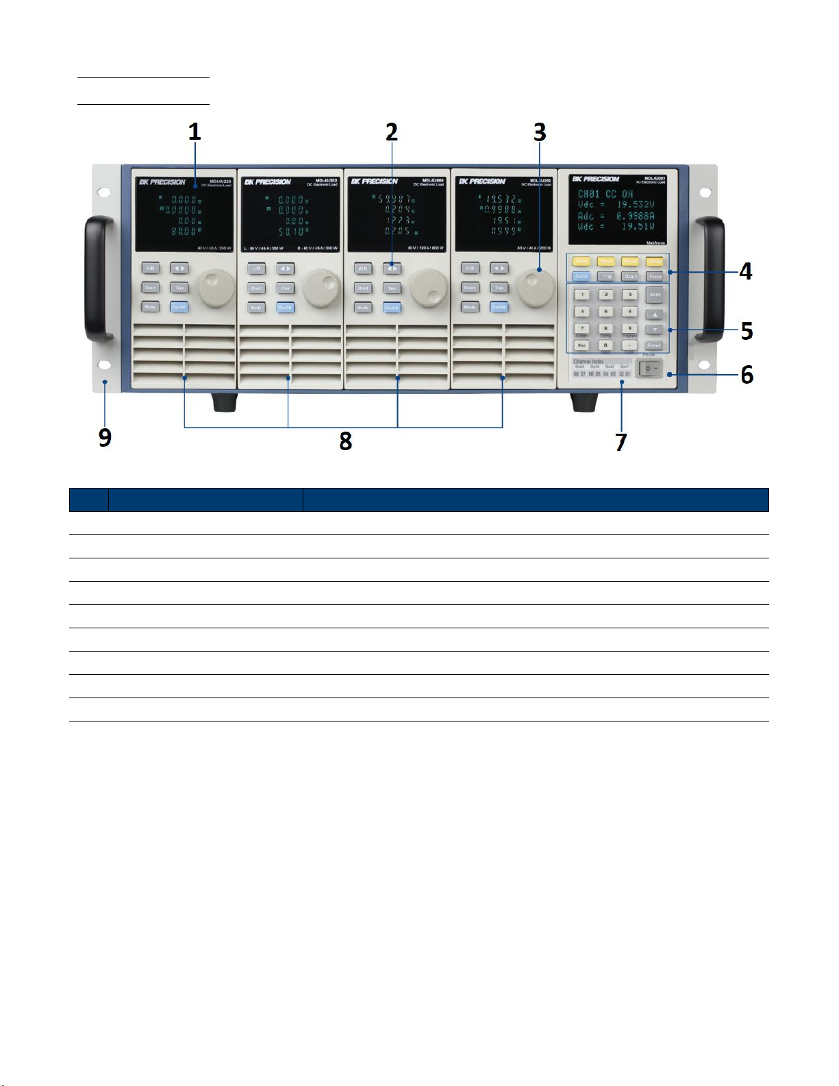
1.5 Front Panel
Figure 1.2 Front Panel
Item Name Description
1 VFD Display Displays electronic load information.
2 Module Panel Keys Controls module functions. Refer to Module section for more details.
3 Rotary Knob Used to change parameters.
4 Mainframe Function Keys Controls each channel’s operating status. Refer to Mainframe for more details.
5 Mainframe Numeric Keypad Used to enter precise values when adjusting parameters.
6 Power Switch Turns the system ON or OFF.
7 Mainframe Index Channel index indicating the corresponding slot’s channels.
8 Modules Select and add any combination of 4 modules including dual-channel modules .
9 Rack-Mount Ear Ears that protrude out on each side to be fastened to the frame with screws.
Table 1.3 Front Panel
Page 12
Introduction 12
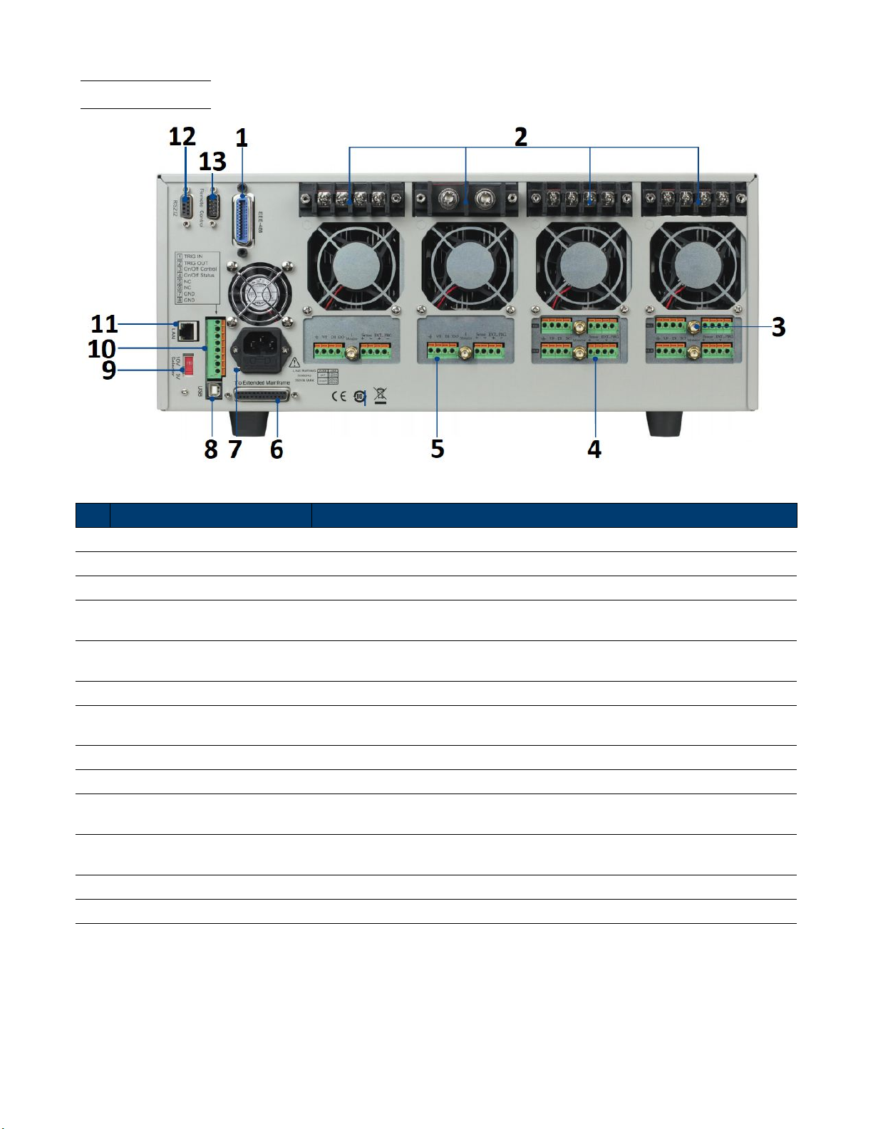
1.6 Rear Panel
Figure 1.3 Rear Panel
Item Name Description
1 GPIB Interface Connect a GPIB cable to remotely control the unit
2 Module Input Terminal Load input termianls.
3 Current Monitoring Connect an external voltmeter or oscilloscope to display the input’s current.
4 Remote Sense/External Control
5 Digital I/O and VF Output
6 Extended Mainframe Connects MDL4U001 to MDL4U002 to expand channel capacity to 16 channels.
7
8 USB Interface Connect a USB type B to type A to remotely control the unit.
9 Line Voltage Selection Select 110/220V±10%AC input.
10
11 LAN Interface
12 RS232 Interface Connect a cable with a two COM interface (DB9) to remotely control the unit.
AC Power Input
& Fuse Box
Trigger I/O &
Load On/O Terminals
Remote Sense:Eliminates the eect of voltage drop in the load leads.
External Control Contol the module using an external analog source.
Digital I/O: Universal output terminal use to control an external instrumnet.
VF Output: Voltage fault indication terminal.
Houses the fuse and the AC input.
Refer to section 8-pin Control Connector for more details.
Connect a Cat 5/6 Ethernet straight-through patch cable to remotely control
the unit.
13 Not Used For factory use only.
Table 1.4 Rear Panel
Page 13
Introduction 13
1.7 Protection Functions
The electronic load has the following protection functions: Overvoltage protection (OVP), overcurrent protection (OCP),
overpower protection (OPP), overtemperature protection (OTP), and local and remote reverse voltage protection (LRV/RRV).
The mainframe will act appropriately once any of the above protections are active. You can press any button on the front
panel to restore the protection function. For example, if the electronic load triggers the overtemperature protection, the
buzzer will alarm, the input will automatically turn o, and the mainframe VFD will display OTP.
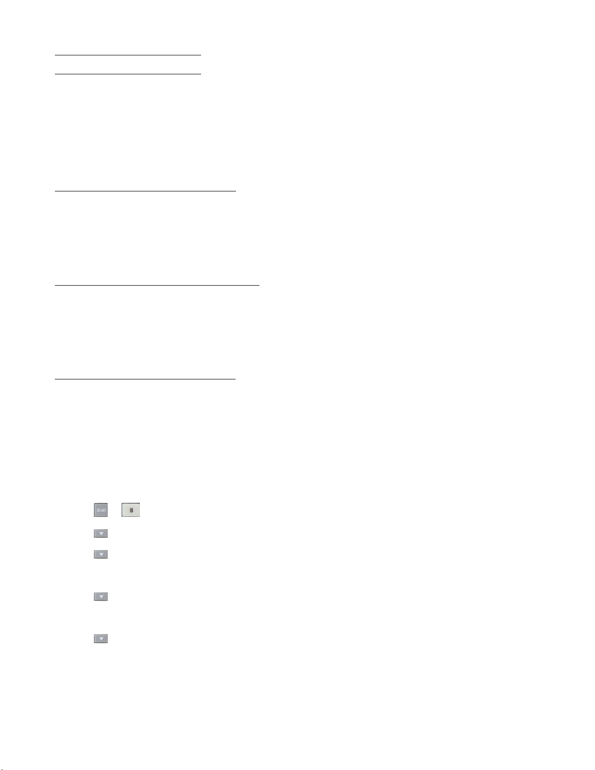
1.7.1 Overvoltage Protection (OVP)
If the OVP circuit has triggered, input will turn o, buzzer alarm will go o, and the status register’s OV and VF bit will
be set. The mainframe will display OVP and the condition will remain until they are reset. Once overvoltage protection
occurs, the 8-pin connector’s VF pin on the rear panel will output TTL high voltage level. You can control the output
state of the power supply under test via this pin (see Figure
1.7.2 Operations to Clear the OVP State
Check whether the input voltage is within the electronic load’s rated voltage or the programmed protection voltage ranges.
If it is outside the range, please disconnect the device under test. Then press any key on the front panel or remotely send
SCPI command PROTection:CLEar. The OVP displayed on the front panel will turn o and the electronic load exits
OVP protection state.
4.16).
1.7.3 Overcurrent Protection (OCP)
The electronic load includes both hardware and software overcurrent protection features.
Hardware OCP - The electronic load’s maximum input current will be limited to approximately 110% of the current range.
Once the hardware OCP is triggered, the status register’s OC bit will be set. When the hardware OCP is removed, the
status register’s OC bit will be reset. Hardware overcurrent protection will not aect the electronic load’s on/o state.
To set the electronic load’s OCP value:
1. Power on the electronic load. Self-test
2. Press
3. Press
4. Press
– Select On and press Enter to conrm.
5. Press
– Input OCP current value and press Enter to conrm.
6. Press
+ to enter Conguration menu.
key to select PProtect and press Enter to go into protection menu.
key to select Alimit State and press Enter.
key to select Alimit Point and press Enter.
key to select Alimit Delay and press Enter.
– Input delay time before alarm and press Enter to conrm.
7. Press Esc key to exit menus
If the electronic load’s current value is above the set overcurrent protection value, the electronic load will automatically
turn o and the VFD will display OCP. At the same time, the OC and PS bits in the status register will be set and remain
until they are reset.
Page 14
Introduction 14
Operations To Clear the OCP State
Check whether the input current is within the electronic load’s rated current or the programmed protection current ranges.
If it is outside the range, disconnect the device under test. Then press any key on the front panel or remotely send SCPI
command PROTection:CLEar. The OCP displayed on the front panel will turn o and the load exits OCP protection
state.
1.7.4 Overpower Protection (OPP)
The electronic load includes both hardware and software OPP features.
Hardware OPP – In the event that the electronic load’s input power exceeds the set power protection limit, the hardware
OPP will limit the power. Once the hardware OPP is triggered, the status register’s OP bit will be set. When the
hardware OPP is removed, the status register’s OP bit will be reset. Hardware overpower protection will not turn the
electronic load’s input o.
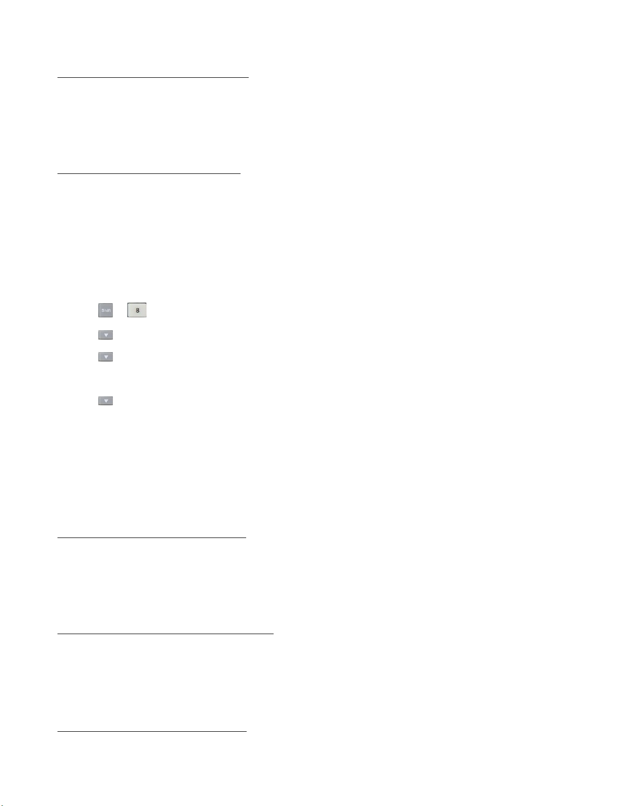
To set the electronic load’s OPP value:
1. Power on the electronic load. Self-test
2. Press
3. Press key to select PProtect and press Enter to go into protection menu.
4. Press key to select Plimit Point and press Enter.
– Input OPP power value and press Enter to conrm.
5. Press key to select Plimit Delay and press Enter.
– Input delay time before alarm and press Enter to conrm.
6. Press Esc key to exit menus
If the electronic load’s power value is above the set overpower protection value, the electronic load will automatically turn
o and the VFD will display OPP. At the same time, the OP and PS bits in the status register will be set and remain
until they are reset.
+ to enter Conguration menu.
Operations to Clear the OPP State
Check whether the input power is within the rated power range or the programmed protection ranges. If it is outside the range, disconnect the device under test. Then press any key on the front panel or remotely send command
PROTection:CLEar. The OPP displayed on the front panel will turn o and the electronic load exits OPP protection
state.
1.7.5 Overtemperature Protection (OTP)
Each module has an overtemperature protection circuit, which will turn o the input if the internal temperature exceeds
safe limits. When the electronic load’s internal circuit temperature is over 85°C, the load will enable OTP. Input will
automatically be turned o and the VFD will display OTP. At the same time the OT and PS bits in the status register
will be set and remain until they are reset.
Operations to Clear the OTP State
When the electronic load temperature has dropped below the protection point, press any key on the front panel or
remotely send command PROTection:CLEar. The OTP displayed on the front panel will turn o and the electronic load
exits OTP protection state.
Page 15
Introduction 15
1.7.6 Reverse Voltage Protection (LRV/RRV)
This function protects the electronic load in case the input DC voltage lines are connected with the wrong polarity. When
a reverse voltage (LRV – local reverse voltage, RRV – remote reverse voltage) connection condition is detected, the input
will immediately turn o, the buzzer will alarm the user, and the status register’s reverse voltage (LRV/RRV) and VF
bits will be set. The mainframe will display LRV/RRV until they are reset.
In this condition, the 8-pin connector’s VF pin will output a high level. You can disconnect the power supply via this
signal (see Figure
4.16).
Operations to Clear the Reverse Voltage State
Check whether the connection is reversed. If so, disconnect the device to be measured to clear the reverse voltage state.
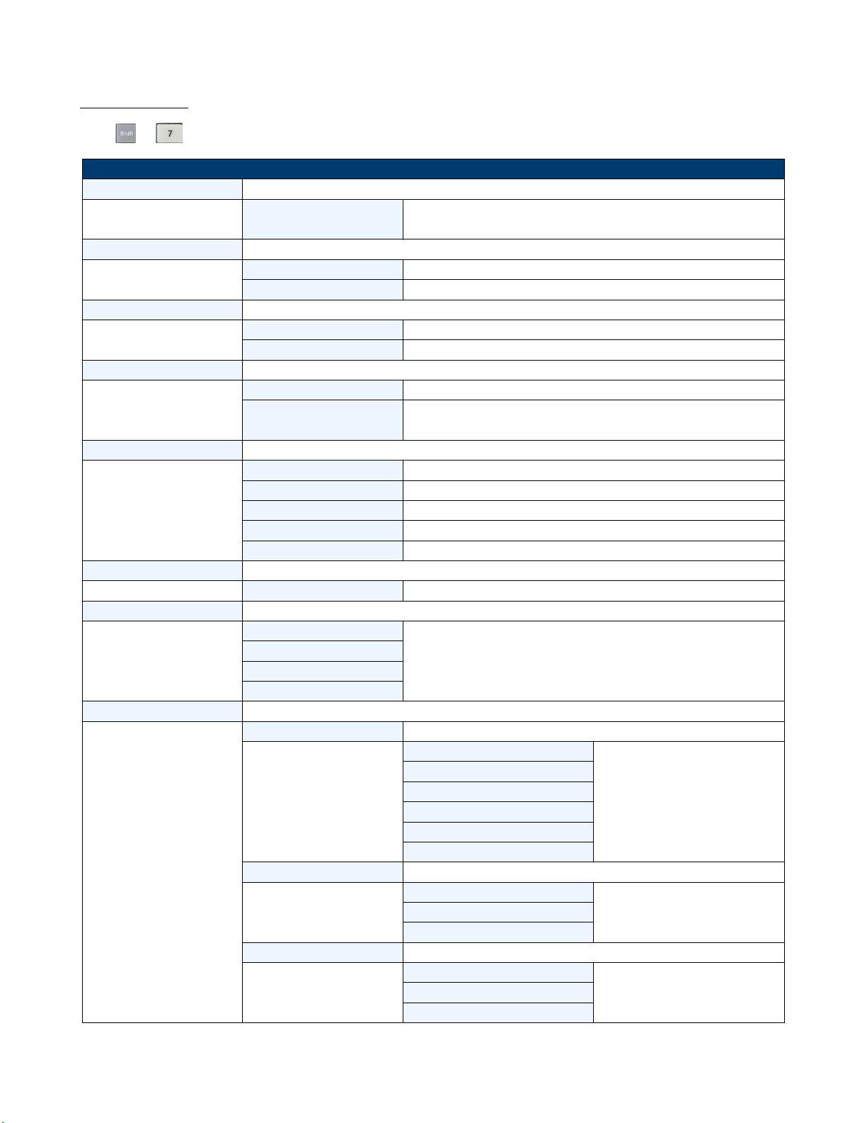
1.8 Menu List
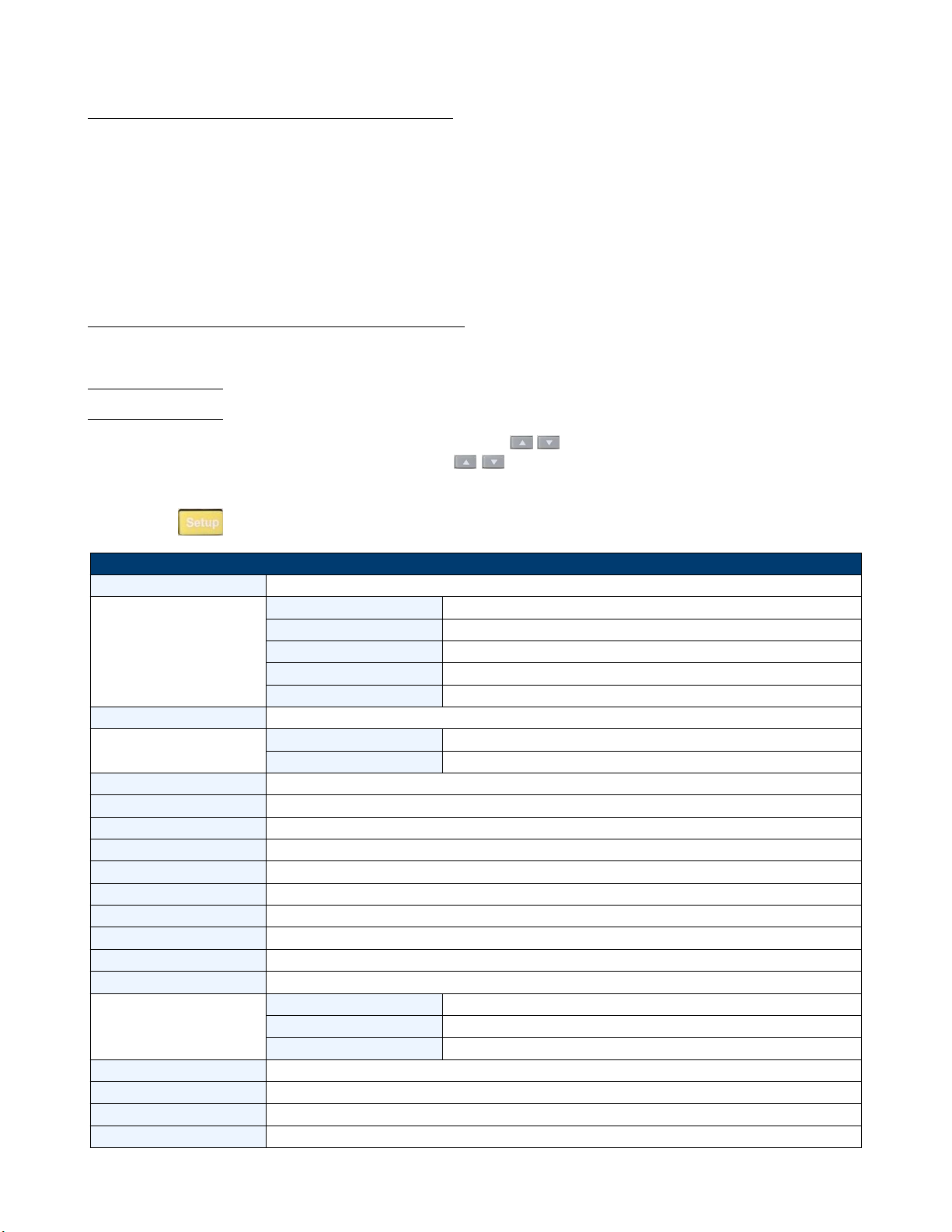
The following menus can be viewed on the VFD display. Use the keys to scroll through the menu list. Press the
Enter key to enter the selected menu function. Use the
key to enter its submenu. Press Esc to go back to the previous menu selection. Pressing number keys can directly select
a channel.
keys to scroll through the VFD screen and press Enter
Press the the
MODE Select working mode
CC/CV RANGE Switch the range
I / V / R / W SET Set the working current/voltage/resistance/power value
Vmax/Amax Set up the maximum voltage/current limit for Automatic test mode
Vmin/Amin Set up the minimum voltage/current limit for Automatic test mode
∫ = 2.500A/us Set the rising slew rate (only in CC mode)
∫ = 2.500A/us Set the falling slew rate (only in CC mode)
TRAN A = 0.00A Set up level A value
Ta = 0.0005S Set up level A width
TRAN B = 0.00A Set up level B value
Tb = 0.0005S Set up level B width
T MODE Set up the transient mode
RLC R = 7500.0Ω Set up the resistance value
RLC L = 0uH Set up the inductance value
RLC C = 10uF Set up the capacitance value
EXIT Exit the setup menu
key to enter the Setup menu.
Setup
CONST CURRENT Load works in CC mode
CONST VOLTAGE Load works in CV mode
CONST RESISTANCE Load works in CR mode
CONST POWER Load works in CW mode
CONST IMPEDANCE Load works in CZ mode
HIGH RANGE Set high range
LOW RANGE Set low range
CONTINUOUS Continuous
PULSE Pulse mode
TOGGLE Toggle mode
Table 1.5 Setup Menu
Page 16
Introduction 16
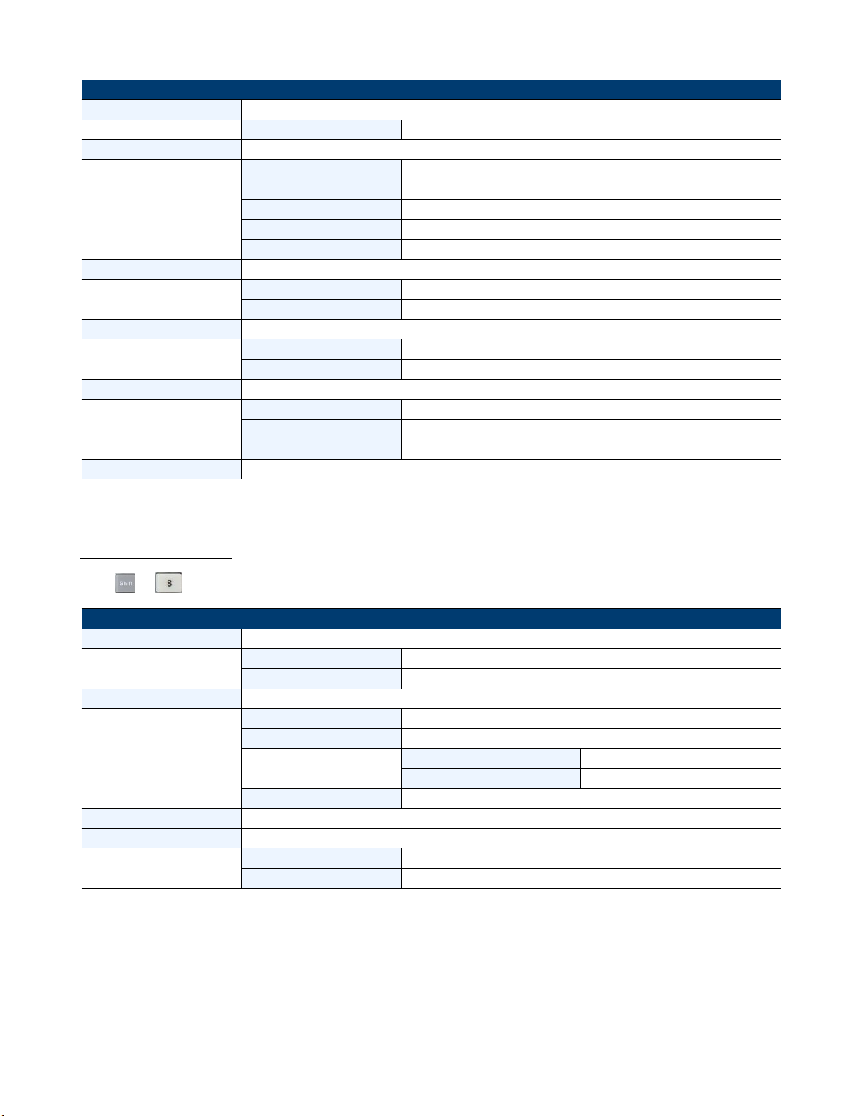
System Menu
Press + to enter the System menu.
MENU
INITIALIZE
INITIALIZE
DEFAULT SET
POWER ON SET
RST (DEFAULT) Set the load’s input state to default at power on
SAV0 Set the load’s input state to SAV0 at power on
BUZZER SET Set up the buzzer state
ON Enable the function
OFF (DEFAULT) Disable the function
LOAD ON KNOB Module knob mode setting
UPDATE (DEF) Real-time update
OLD
TRIGGER SOUR. Set up the trigger mode
MANUAL (DEF) Manual trigger
EXTERNAL External signal trigger mode
HOLD Hold trigger mode
BUS Bus trigger mode
TIMER Timer trigger
TRIGGER TIMER Trigger timer setting
TRIGGER TIMER SET Set the time of the trigger timer
COMMUNICATION Select the interface for remote communication
RS232 (DEF)
USBTMC-USB488
GPIB
ETHERNET
RS232 SET
BAUDRATE SET Set up the communication baud rate
PARITY SET Set up the communication parity
HANDSHAKE SET Select the handshake protocol
Resume all conguration to default settings
No update (when turning load ON/OFF, original value before
use of rotary knob will be set)
4800 (DEFAULT)
9600
19200
38400
57600
115200
NONE (DEFAULT)
ODD
EVEN
NONE (DEFAULT)
CTS/RTS
XON/XOFF
Table 1.6 System Menu
Page 17
Introduction 17
System Menu Cont...
GPIB ADDRESS GPIB address setting
GPIB ADDRESS SET Set up communication address
ETHERNET SET Ethernet settings
GATEWAY SET Gateway setting
IP SET IP setting
MASK SET Mask setting
PORT SET Port setting
EXIT
EXPAND MODULE Module expansion
ON Enable the function
OFF (DEFAULT) Disable the function
LANGUAGE SET Communication protocol
SCPI (DEFAULT) SCPI protocol
EXTEND TABLE Expand SCPI protocol, compatible with others
ABOUT Mainframe production information
MDL### Mainframe production model number
SN: ########## Mainframe production serial number
VER: 1.43 Mainframe software version
EXIT
Table 1.7 System Menu Cont...
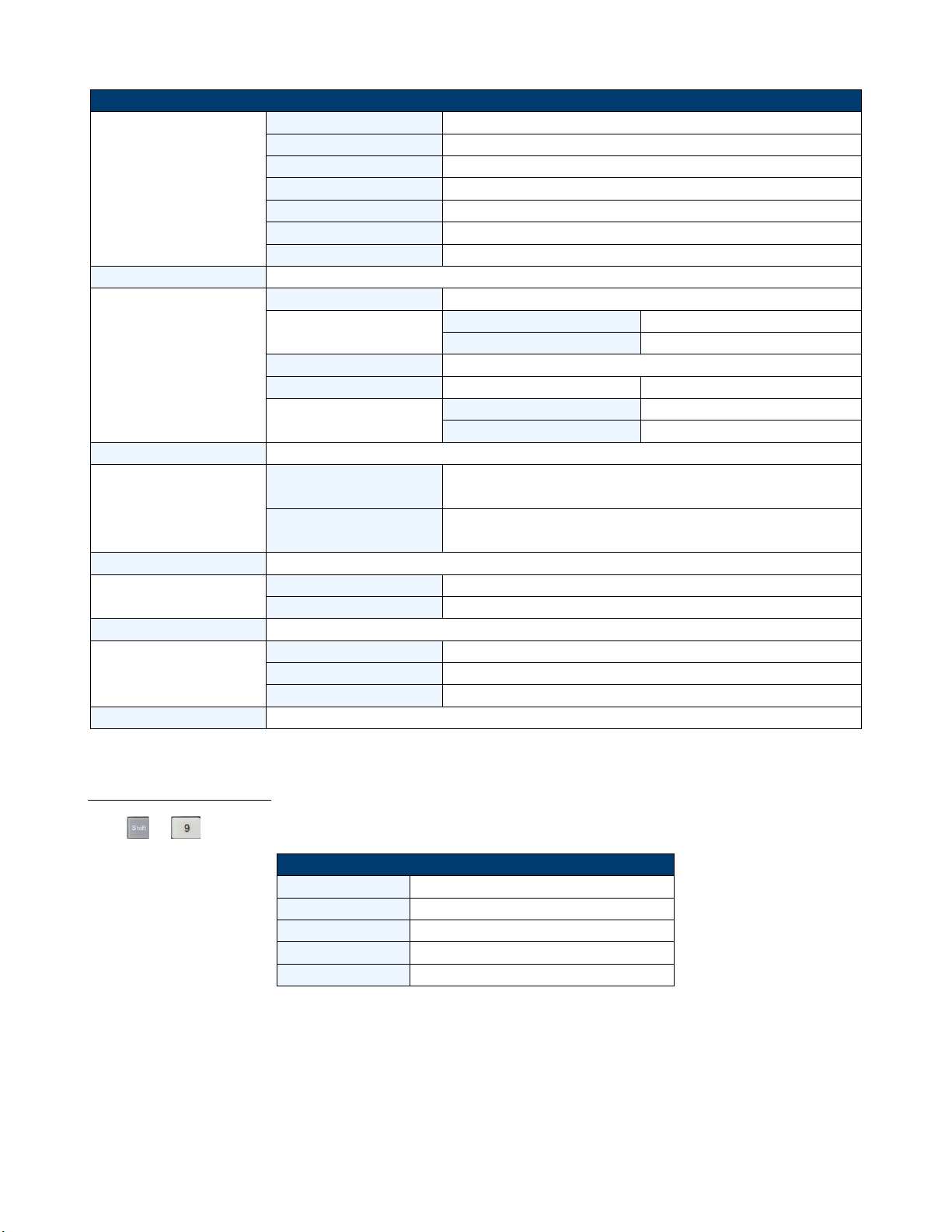
Conguration Menu
Press + to enter the Conguration menu.
Conguration Menu
SYNC ON SET Setup Synchronization ON / OFF function
ON (DEFAULT) Turn on synchronization function
OFF Turn o synchronization function
VON
VON POINT Set the load’s Von point
VON LATCH Von latch state
ON (DEFAULT) Turn on Von latch
OFF Turn o Von latch
EXIT Exit the menu
AVERAGE COUNT Average count setting 2^X (adjustable from 2^2 to 2^16)
V AUTORANGE Auto switching voltage range
ON (DEFAULT) Enable this function
OFF Disable this function
Table 1.8 Conguration Menu
Page 18
Introduction 18
Conguration Menu Cont...
ALIMIT POINT Set up software current protection value
ALIMIT DELAY Set up software current protection delay
PLIMIT POINT Set up software power protection value
PLIMIT DELAY Set up software power protection delay
ON TIMER STATE Set up LOAD ON timer state
ON TIMER SET Set up LOAD ON timer time
EXIT Exit the menu
LIST
FUNCTION MODE Select mode
FIXED Choose xed operation mode
LIST Choose list operation mode
RECALL LIST Recall list operation le
EDIT LIST Edit list operation le
HIGH RANGE Edit high range of list operation
LOW RANGE Edit low range of list operation
EXT. CTRL SET External analog control function
ON Turn on external analog control function
OFF (DEFAULT) Turn o external analog control function
REM SENSE SET Remote sense function
ON Enable remote sense function
OFF (DEFAULT) Disable remote sense function
ABOUT Module production information
MDL### Channel production model
SN:######## Channel production serial number
VER: 1.35 Channel software version
EXIT Exit the menu
Table 1.9 Conguration Menu Cont...
Automatic Test Menu
Press + to enter the Automatic Test menu.
Automatic Test Menu
PROGRAM
RUN PROGRAM Run the testing le
RECALL PROG Recall the testing le
EDIT PROGRAM Edit the testing le
EXIT
Table 1.10 Automatic Test Menu
Page 19
Installation
2.1 Inspection
This instrument was carefully inspected before shipment. Upon receipt, inspect the instrument for damage that might
have occurred during transit. If any sign of damage is found, please notify your B&K Precision distributor.
The following standard and optional accessories are provided with each mainframe or module.
Mainframes include:
• Power cord
• USB cable (MDL4U001 only)
• Mainframe extension cable accessory (MDL4U002 only)
Modules include:
• Certicate of calibration
Note:
Ensure the presence of all the items above. Notify your B&K Precision distributor if anything is missing.
2.2 Cleaning
Use a dry cloth or one slightly dampened with water to clean the external case parts. Do not attempt to clean internally.
Warning:
To prevent electric shock, please unplug the power cord connected to the unit before cleaning.
2.3 Installing Modules
Caution:
Static electricity may damage load modules. Please install modules according to
standard electrostatic prevention. Avoid touching joints and circuit boards.
Any combination of modules up to 2400 W total in the MDL4U001 mainframe in any order. This also applies to the
MDL4U002 mainframe extension, allowing a maximum of 4800 W total when connecting the MDL4U001 and MDL4U002
together. The procedure of installing modules to the mainframe extension is the same as that of the MDL4U001
mainframe.
Page 20
Installation 20
Installation Procedure
1. Turn the mainframe o and disconnect the power cord.
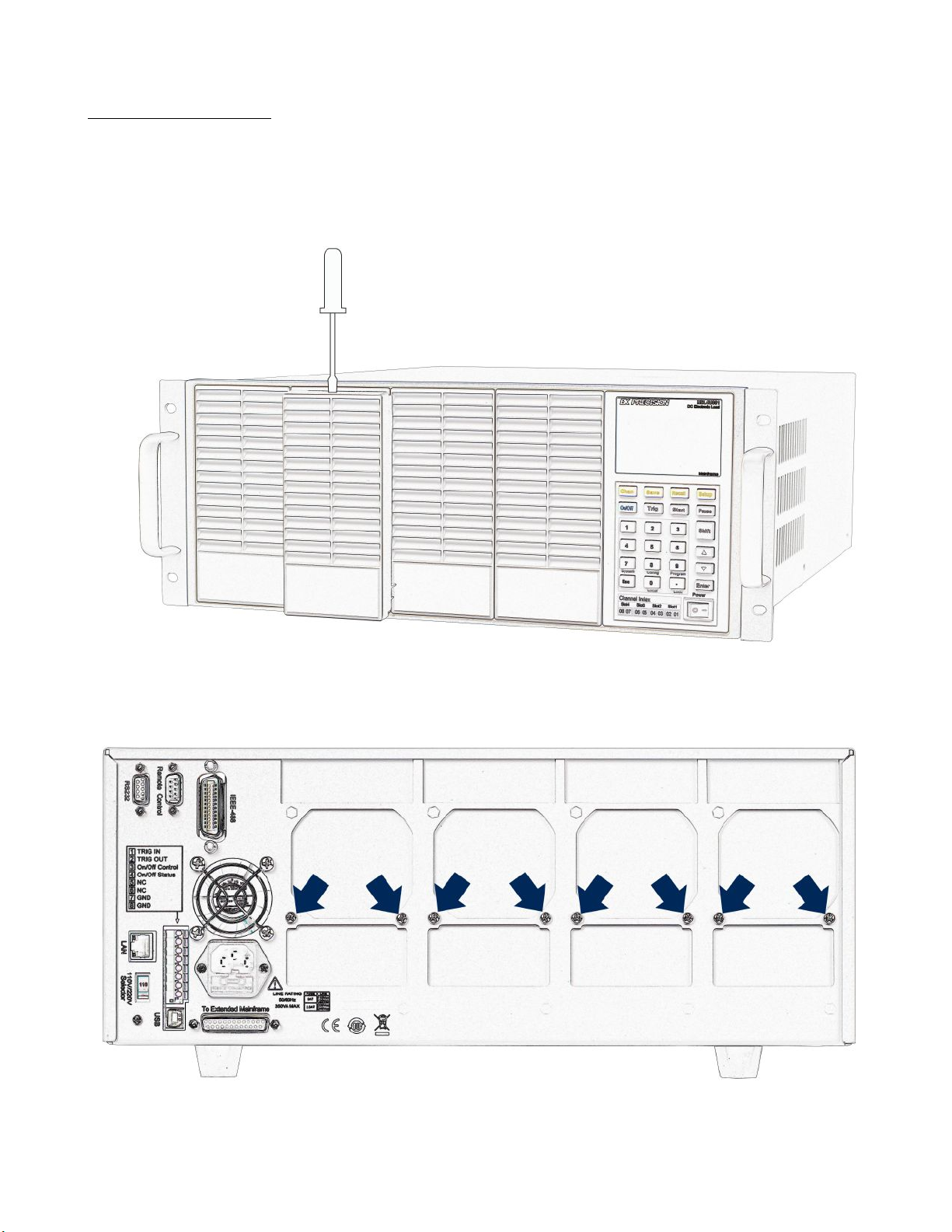
2. Remove the plastic cover with a at-blade screwdriver.
Figure 2.1 Removing Covers
3. Loosen the screws on the rear panel and remove the metal place holders.
Figure 2.2 Removing Rear Cover Screws
Page 21
Installation 21
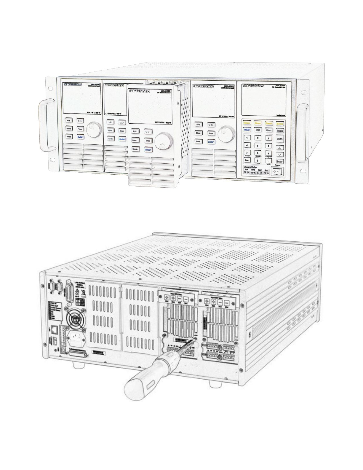
4. Insert and slide the selected modules into the slot.
Figure 2.3 Module Installation
5. Insert and tighten module screws on rear panel.
Figure 2.4 Tighten Module Rear Screws
6. Install more modules in other slots following the same process (stes 2 through 5).
7. Reconnect the power cord.
Page 22
Installation 22
2.4 Channel Number
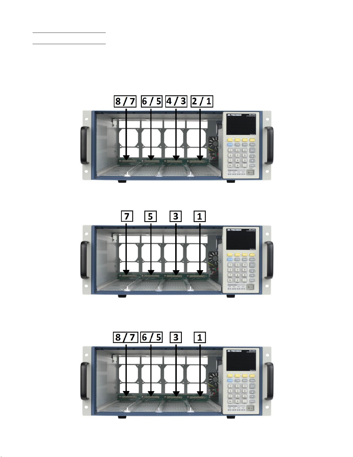
The channel number for all modules is determined by the location of the modules in relation to the mainframe and
ordered from right to left. With the MDL4U001 mainframe, the total number of channels is 8. Channels 1 and 2 are next
to the mainframe front panel, while channels 7 and 8 are located on the left side. Load channel number is xed even if
the location is unoccupied. Dualchannel modules such as the MDL4U252 and MDL4U302 have two channels. If it is a
single-channel module, the channel number is automatically assigned the rst number of the slot. Figure
default channel number order.
2.5 shows the
Figure 2.5 Channel Number
Figure
2.6 shows an examples of how channels are assigned when single-channel modules are installed.
Figure 2.6 Single Channel Modules Numbering
Figure
2.7 shows an examples of how channels are assigned when single-channel modules and dualchannel modules are
installed are installed.
Figure 2.7 Single and Dual Channel Modules Numbering
Page 23
Installation 23
2.5 Location
The operating temperature of the MDL4U Series DC Electronic Load is 0 to 40 ℃. A fan cools the electronic load by
drawing air through both the top and front, and then exhausting it out the back. Therefore, the electronic load must be
installed in a location that allows sucient space on the front and back of the unit for adequate air circulation.
Minimum clearances for bench operation are 2 inches from the top and 3 inches from the front and back. If there are
radiator fans in your cabinet, please avoid installing the load near the fan, since it may limit air circulation of the load.
If you are installing equipment on top of your electronic load in the cabinet, use a ller panel above the unit to ensure
adequate air circulation.
Caution:
Do not block the fan exhaust at the rear of the load. When the load is used on a
bench, make sure there is enough space on the front and rear of the equipment for air
circulation.
2.6 Input Voltage Selection
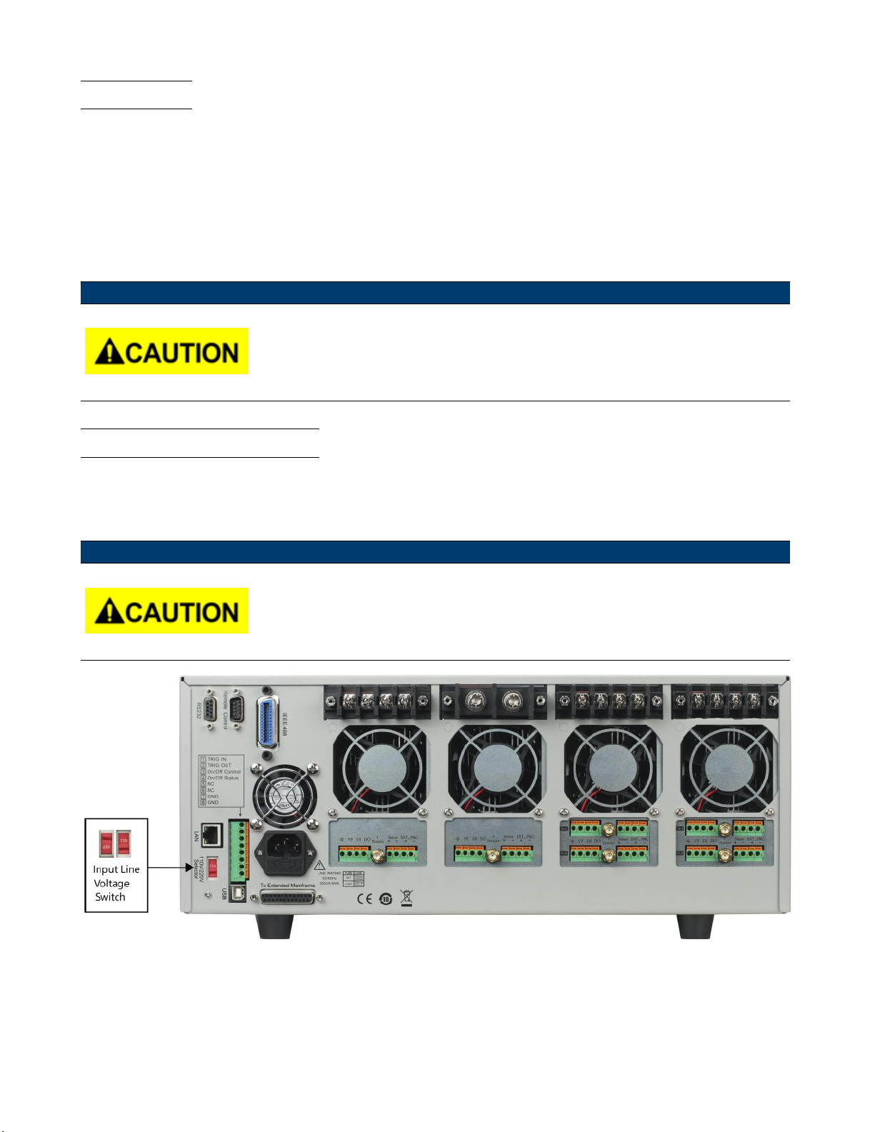
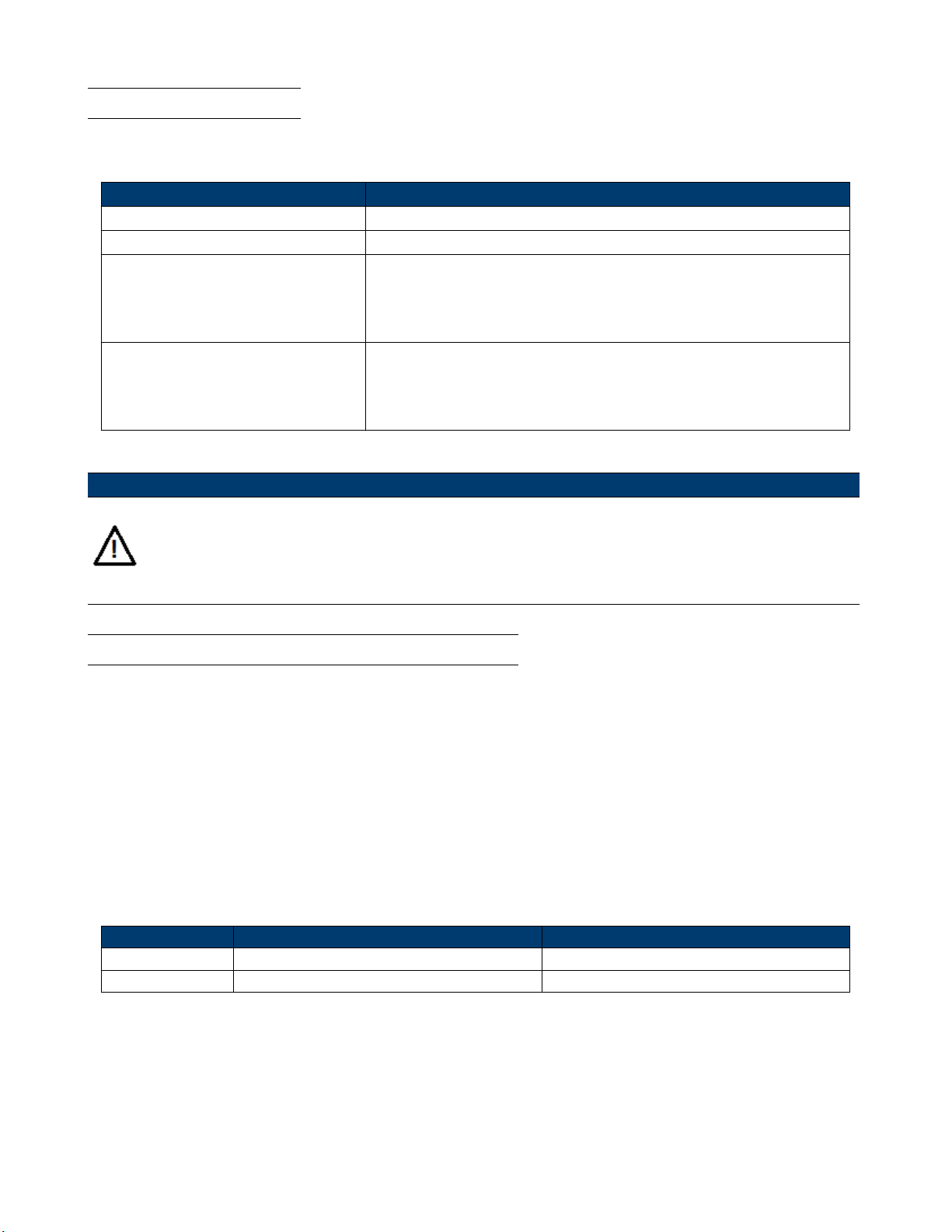
The electronic load can work under 110/220V±10% AC input, identied by an input line voltage switch on the rear (refer
to Figure
choose your input line voltage, install appropriate fuse (refer to Table
Caution:
2.8). If the indicated line voltage does not match your region, please use the switch in the back of the unit to
2.2 below), and then insert power cord.
Check to make sure correct fuse is installed when line voltage is switched.
Figure 2.8 Input Voltage Selection
Page 24
Installation 24
2.7 Turn-On Checkout
When you turn on the electronic load, the front-panel display will light up briey while the electronic load performs its
power-on self-test. The following table shows the procedure of the self-test.
Mainframe VFD Display Description
BIOS Ver 1.20 VFD displays software version
SYSTEM SELF TEST System self-check
CH1/2/3/4/5/6/7/8
SCAN...
.7.5.3.1
Detecting all installed modules
e.g.CH01 CV OFF
Vdc=0.0000V Adc=0.0000A
Wdc= 0.00W
Warning:
Your electronic load is equipped with a 3-wire grounding type power cord; the third conductor being
ground. The electronic load is grounded only when the power-line cord is plugged into an appropriate
receptacle. Do not operate your power supply without adequate cabinet ground connection.
Displays information of channel 1 or the leftmost channel. Use up and
down key to select other channels.
Table 2.1 Turn-On Procedure
2.8 If the Electronic Load Does Not Turn On.
Use the following troubleshooting steps to help solve problems you might encounter when turning on the instrument:
1. Verify that there is AC power to the electroic load.
First, verify that the power cord is rmly plugged into the power receptacle on the rear panel of the electronic load.
You should also make sure the power source you plugged the electronic load into is energized. Then check to see
that the electronic load is turned on.
2. Verify the power line voltage setting.
The line voltage is set to the proper value for your country (110VAC or 220VAC) when the electronic load is shipped
from factory. Change the line voltage setting if it is not correct.
3. Verify that the correct power line fuse is installed and not burned out.
If fuse is blown, please replace it according to the following specication.
Product Fuse specication (110 VAC) Fuse Specication (220 VAC)
MDL4U001 T5A, 250 V T2.5A, 250 V
MDL4U002 T5A, 250V T2.5A, 250 V
Table 2.2 Fuse Specications
4. Replace fuse.
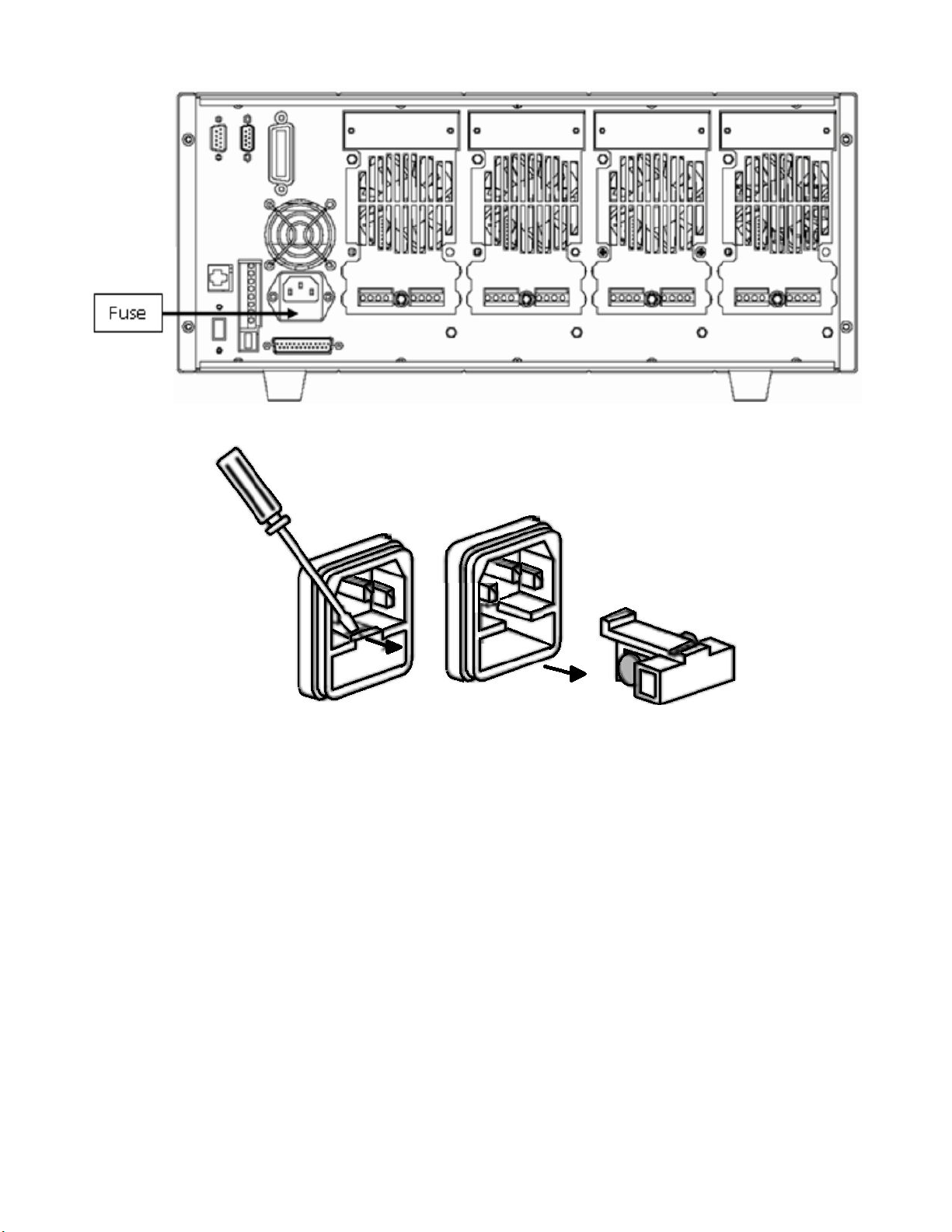
Use a at-bladed screwdriver to open the small plastic cover under the AC input connector on the rear panel of the
load and then replace with matching fuse.
Page 25
Installation 25
Figure 2.9 Fuse Location
Figure 2.10 Fuse Removal
Page 26
Load Connection
Warning:
To satisfy safety requirements, load wires between the electronic load and the device under test (DUT)
should have a current rating high enough not to overheat while carrying the short-circuit output current.
Never make connections between the electronic load and a DUT while the electronic load inputs are turned
ON and/or the DUT has live power at its output.
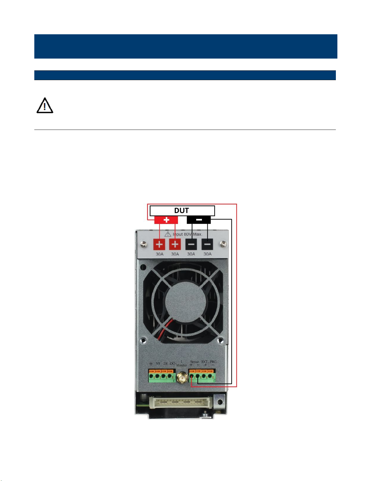
Before connecting the device to be measured to the electronic load, please remove the cover on the output terminals of
the load and cover it after completing the connection. Please pay attention to the type, length, and polarity when wiring.
Avoid using wires of minimum specication of heating, which are unable to supply good load regulation.
Generally speaking, if the wires are short enough, they can control a voltage drop of less than 0.5 V. In addition, bonding
them together can reduce induction and noise. Connect wire from positive terminal of module to positive terminal of
device. Similarly, connect the corresponding negative terminal. Figure
with the device to be measured.
3.1 illustrates a typical connection of the module
Figure 3.1 Module Input
There are two positive terminals and two negative terminals on the rear panel of every module. Single terminal connection
is adequate when the input current is less than 30 A.
Page 27
Load Connection 27
Warning:
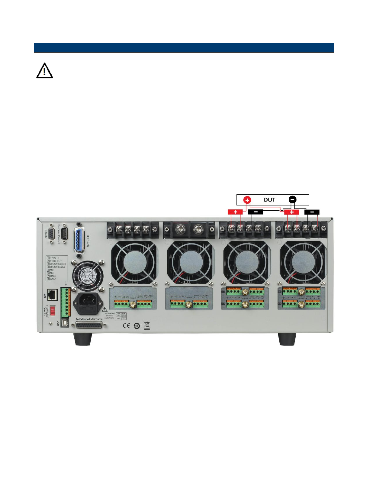
Each terminal can carry up to 30 A current. Double-terminal connection is needed when the input current
is more than 30 A. Refer to Figure
terminal connection.
3.1 - Connection of Load and Device Under Test (DUT) for double-
3.1 Parallel Connection
Parallel connection can be applied between modules of the same model to increase current and power dissipation, but it
cannot be applied between dierent modules.
Modules can be paralleled in CC, CR, or CW mode, but cannot be paralleled in CV or CZ mode.
Each module will dissipate the power it has been programmed at. For example, after being paralleled, two single-channel
modules rated at 80V/40A/300W can dissipate up to 80V/80A/600W.
Figure
3.2 illustrates the paralleled connection for increased power dissipation.
Figure 3.2 Parallel Module Connection
Page 28
Load Connection 28
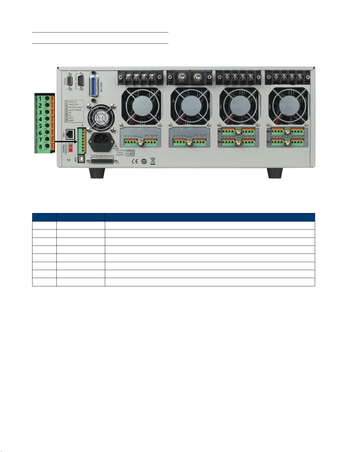
3.2 Mainframe 8-pin Control Connector
The mainframe’s 8-pin control terminal on the rear panel is shown below. This is used for external trigger and ON/OFF
control connections.
Figure 3.3 Mainframe Rear Panel 8-pin Control Connnector
Pin Signal Description
1 Trigger IN Trigger Signal Input
2 Trigger OUT Trigger Signal Output
3 ON/OFF IN Synchronization ON/OFF Control Signal Input
4 ON/OFF OUT Synchronization ON/OFF Signal Output
5 NC No Connection
6 NC No Connection
7 GND Ground
8 GND Ground
Table 3.1 Control Connector Pinout
Page 29
Load Connection 29
3.3 External Trigger Connections
There is ve kinds of trigger modes.To set the trigger mode:
1. Press the (
2. Press the
3. Press the
+ ) to enter the System menu.
navigation keys to select Trigger Source.
navigation keys to select the desired trigger mode.
3.3.1 Trigger Modes
Manual Trigger Mode
To use the front panel trigger mode, set the trigger source to MANUAL.
Once trigger mode is set to manual press the
External Trigger Mode
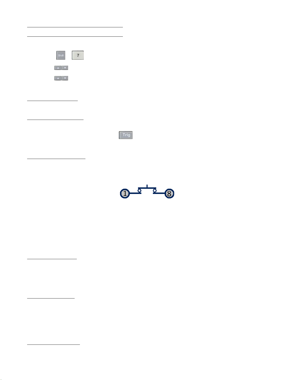
To use rear panel trigger mode, set the trigger source to EXTERNAL. Inputting a TTL level pulse (>10 us) to the
trigger signal input (pin 1) of mainframe’s
operation. Figure
3.4 shows one way to produce a trigger signal.
Mainframe 8-pin Control Connector on the rear panel will enable a trigger
Figure 3.4 Contact
with a TTL Pulse Source
When making contact with a TTL pulse source, it produces a trigger to change the setting value (voltage, current,
resistance, etc.), e.g. switch in transient mode, or create a pulse in dynamic pulse mode. At the same time, it will output
a trigger signal on pin 2.
Hold Trigger Mode
To use hold trigger mode, set trigger source to HOLD. Then send the TRIG:IMM command to trigger the electronic
load. Pin 2 of 8-pin Control Connector on the rear will also output a corresponding trigger signal when the electronic
load receives the TRIG:IMM command.
Bus Trigger Mode
To use BUS trigger mode, set the trigger source to BUS. Connect the electronic load by GPIB, USB, or Ethernet
communication interface.
When the TRIG command is received, the load will produce a trigger signal.
Timer Trigger Mode
To use timer trigger mode, set the trigger source to TIMER. Set the TRIGGER TIMER’s time, and the electronic load
will trigger at specied trigger timer setting and also produce a trigger signal on rear Trigger Out pin.
Page 30
Load Connection 30
3.4 External ON/OFF Control Connection
ON/OFF IN (pin 3 of rear 8-pin Control Connector) is used to toggle the multi-channel electronic load inputs ON or
OFF. When ON/OFF IN pin receives a TTL level pulse (>10us), the ON/OFF state of the load will toggle. SYNC ON
SET function can be set to ON for multiple channels to toggle more than one channel at a time.
ON/OFF OUT (pin 4 of rear 8-pin Control Connector) indicates ON/OFF state of the multi-channel electronic load. If
SYNC ON SET function of any specic channel is set to ON and the channel’s input state is ON, pin 4 outputs a low
TTL level signal. If the input state is o, pin 4 outputs a high TTL level signal.
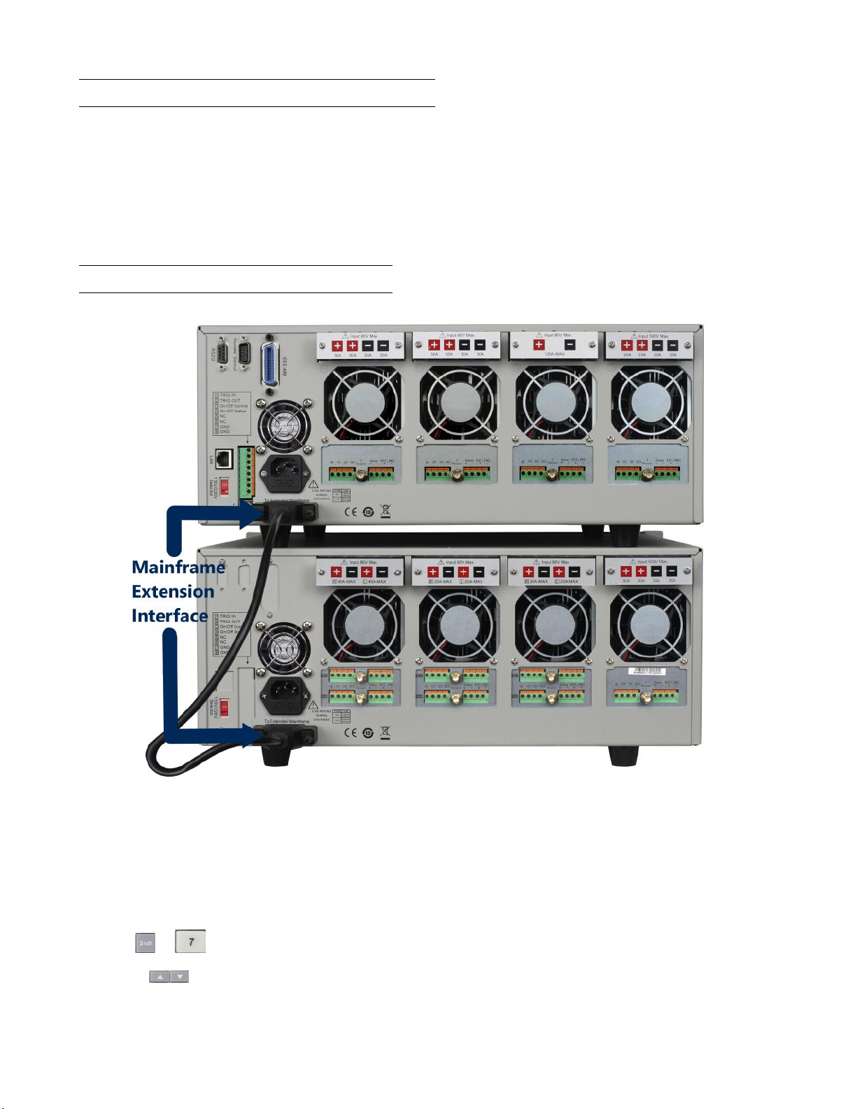
3.5 Mainframe Extension Connection
Figure 3.5 Mainframe Extension Connection
The Extended Mainframe interface is used to connect the mainframe extension to expand the number of channels. Up
to 16 total channels can be supported when mainframe is connected to the mainframe extension.
Procedure:
1. Use expansion cable to connect the mainframe extension interface between the mainframe and mainframe extension.
2. Press
3. Use the
4. Select Expand Module and choose ON to enable expand function.
5. Press Enter to conrm.
+ to enter System menu.
keys to navigate through menu.
Page 31
Load Connection 31
3.6 PC Control Connection
The MDL4U Series DC Electronic Load can achieve remote control via USB, RS-232, LAN, or GPIB interface, but only
one interface can be used at a time.
To choose the interface:
1. Connect communication cable before powering on.
– Do not hot plug, as it may damage the communication interface of the electronic load.
2. Power on the electronic load.
3. Select the channel number
4. Press the
5. Select Communication and select the desired interface.
– Press Enter to conrm.
6. The display will return to the main menu.
Note:
When using RS232, GPIB, or LAN the commuincation settings must be set. To do so select RS232 Set,
GPIB Address, or Ethernet Set from the system menu.
See the Menu List for full listing of menus and submenus applicable to all other remote interfaces.
+ to enter the System menu.
via keys.
Page 32
Operations
4.1 Operation Modes
The electronic load has the following operation modes:
1. Constant Current (CC) Mode
2. Constant Voltage (CV) Mode (CV) Mode
3. Constant Resistance (CR) Mode
4. Constant Power (CW) Mode
5. Constant Impedance (CZ) Mode
4.1.1 Constant Current (CC) Mode
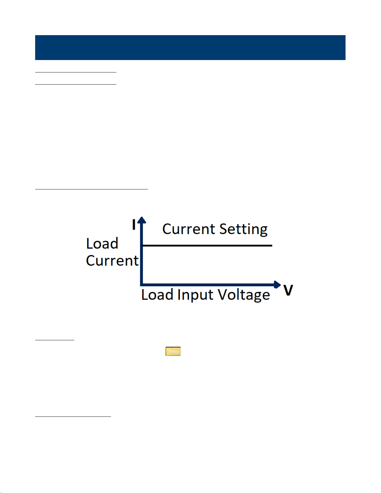
In CC mode the electronic load will sink a current in accordance with the programmed value regardless of the input
voltage.
Figure 4.1 Constanct Current Mode
CC Ranges
When working in CC mode, you can Press the the key to enter the RANGE menu. Two overlapping ranges can be
selected: LOW RANGE or HIGH RANGE. Current can be edited in either of the two ranges.
Low range will supply higher accuracy and better resolution when you set lower current. If any value you set is outside
the maximum value of the LOW RANGE, you should select HIGH RANGE. If the electronic load is in remote control
mode, you can use the CURR:RANG command to switch current range.
CC Vmax/Vmin Limits
The Vmax and Vmin parameters refer to the voltage high and low limit for the automatic test mode. During automatic
test mode, the device test under test (DUT) must be operating within the congured values for the test to PASS upon
completion. If the DUT operates outside the congured values, the test will FAIL upon completion.
Page 33
Operations 33
Note:
These parameters are used for Automatic Test ONLY.
Immediate Current Value
Set the current level via front panel or by sending SCPI command CURR n. If the load is in CC mode, the new current
level setting immediately changes the input at a rate determined by the slew rate. If the load is not in CC mode, the
current level setting will be saved for use until mode is switched to CC mode.
Transient Current Level
A/B transient current level can be set on the front panel or by remote operation. The load can continuously toggle
between the two levels when transient operation is turned on.
Set Slew Rate
The current slew rate determines the rate at which the input current to a module changes to a new programmed value.
You can set the current level’s rise/fall slew rate on the front panel or by remote operation. The programmed slew rate
is immediately in eect to the triggered and transient current level changes.
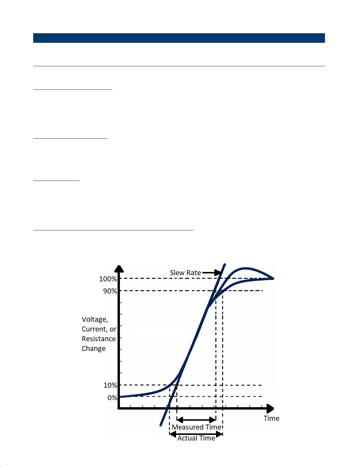
Slew Rate Measurement and Actual Transition Time
Current slew rate is dened as the change in current over time. A programmable slew rate allows a controlled transition
from one load setting to another. The actual transition time is dened as the time for the input to change from 10% to
90%, or 90% to 10% of the programmed current values. The graph below illustrates slew rate measurements.
Figure 4.2 Slew Rate Measurement
Page 34
Operations 34
Between the 10% and 90% region, the slew rate can be measured by observing the steepest slope portion. In case of very
large load changes, e.g. from no load to full load, the actual transition time will be larger than the expected (measured)
time. For this reason, the rmware allows the user to program slew rate values outside of the specied slew rate ranges.
The minimum transition time for all programmable slew rates is also limited in cases where the transition from one setting
to another is very small, due to bandwidth limitations of the load.
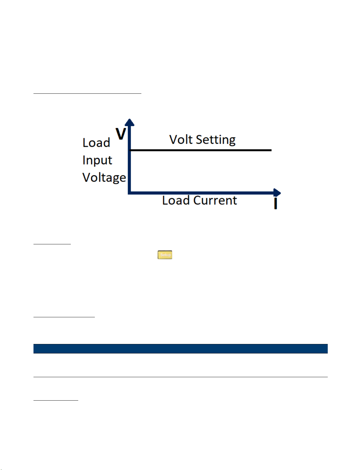
4.1.2 Constant Voltage (CV) Mode
In CV mode, the electronic load will attempt to sink enough current to cnotrol the source voltage to the programmed
value.
Figure 4.3 Constanct Voltage Mode
CV Ranges
When working in CV mode, you can Press the the key to enter the RANGE menu. Two overlapping ranges can be
selected: LOW RANGE or HIGH RANGE. Voltage can be edited in either of the two ranges.
Low range will supply higher accuracy and better resolution when you set lower current. If any value you set is outside
the maximum value of the LOW RANGE, you should select HIGH RANGE. If the electronic load is in remote control
mode, you can use the VOLT:RANG command to switch voltage range.
Amax/Amin Limits
These parameters refer to the current high and low limit for the automatic test mode. During automatic test mode, the
device under test (DUT) must be operating within the congured values for the test to PASS upon completion. If the
DUT operates outside the congured values, the test will FAIL upon completion.
Note:
These parameters are used for Automatic Test ONLY.
Voltage Level
Set the voltage level on front panel or by sending SCPI command VOLT n. If the load is in CV mode, the new setting
immediately changes the input. If the electronic load is not in CV mode, the set voltage level will be saved in the
instrument for use until the mode is switched to CV mode.
Page 35
Operations 35
Transient Voltage Level
A/B transient voltage level can be set on front panel or by remote operation. The electronic load can continuously toggle
between the two levels when transient operation is turned on.
4.1.3 Constant Resistance (CR) Mode
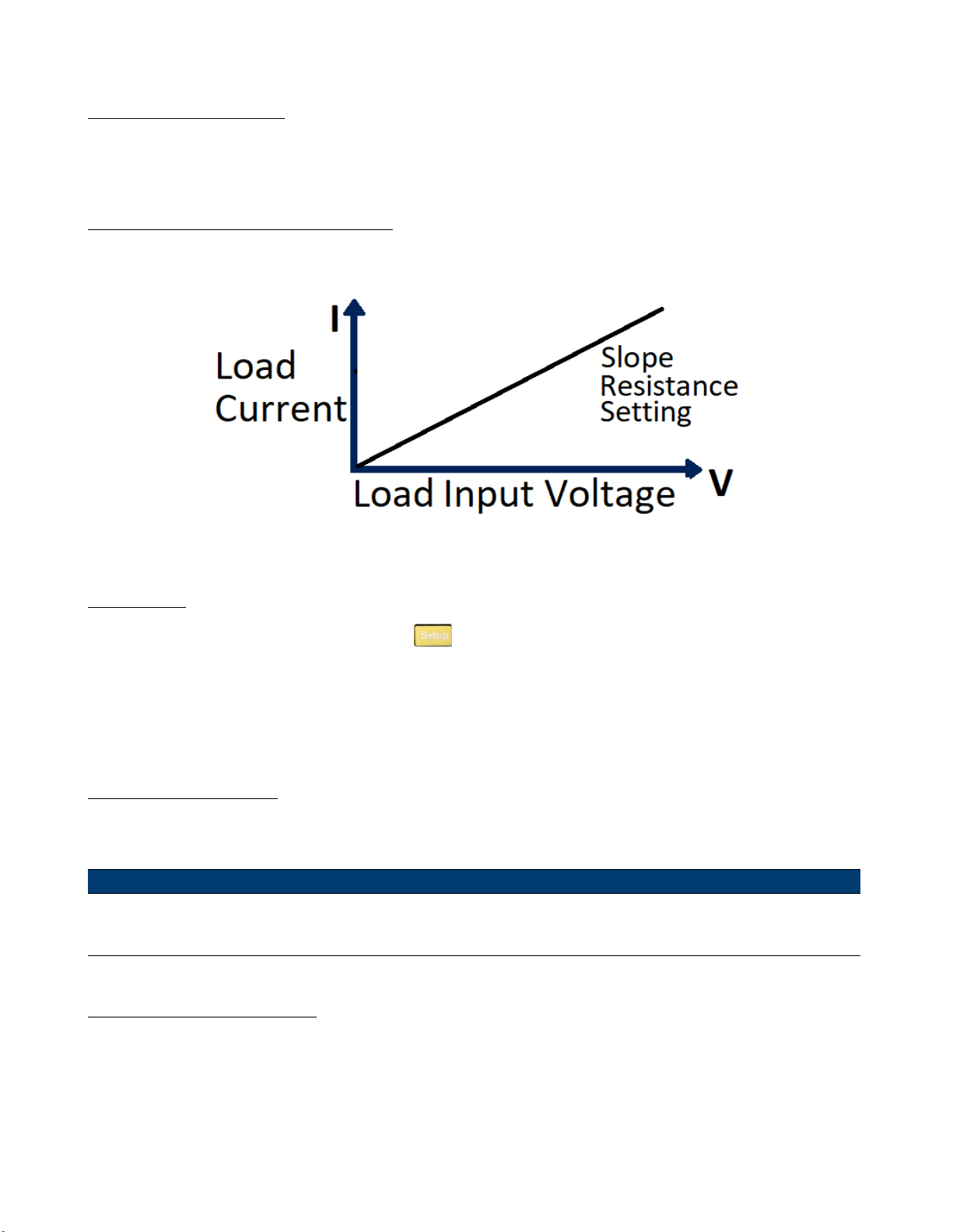
In CR mode, the electronic load is equivalent to a constant resistance, as shown in gure 4.4.
The electronic load will linearly change the current, according to the input voltage.
Figure 4.4 Constant Resistance Mode
CR Ranges
When working in CR mode, you can Press the the key to enter the RANGE menu. Two overlapping ranges can be
selected: LOW RANGE or HIGH RANGE. Resistance can be edited in either of the two ranges.
Low range will supply higher accuracy and better resolution when you set lower resistance. If any value you set is outside
the maximum value of the LOW RANGE, you should select HIGH RANGE. If the electronic load is in remote control
mode, you can use the RES:RANG command to switch resistance range.
CR Vmax/Vmin Limits
These parameters refer to the voltage high and low limit for the automatic test mode. During automatic test mode, the
device under test (DUT) must be operating within the congured values for the test to PASS upon completion. If the
DUT operates outside the congured values, the test will FAIL upon completion.
Note:
These parameters are used for Automatic Test ONLY.
Immediate Resistance Level
Set the resistance level via front panel or by sending SCPI command RES n. If the load is in CR mode, the new resistance
level setting immediately changes the input. If the load is not in CR mode, the resistance level setting will be saved for
use until mode is switched to CR mode.
Page 36
Operations 36
Transient Resistance Level
A/B transient resistance level can be set on front panel or by remote operation. The load can continuously toggle between
the two levels when transient operation is turned on.
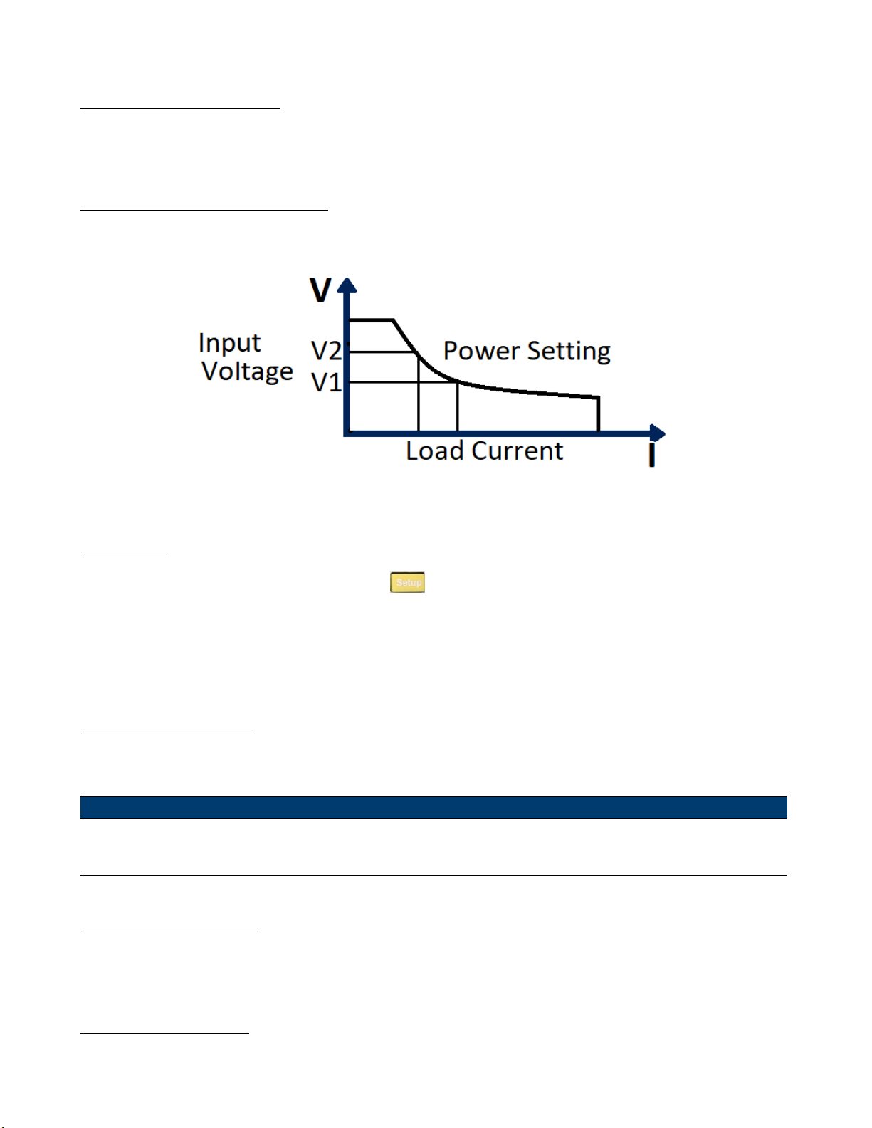
4.1.4 Constant Power (CP) Mode
In CP mode, the electronic load will consume a constant power. When input voltage increases, the input current will
dexrease, while power (P = V * I) will remain the same.
Figure 4.5 Constant Power Mode
CP Ranges
When working in CW mode, you can Press the the key to enter the RANGE menu. Two overlapping ranges can
be selected: LOW RANGE or HIGH RANGE. Power can be edited in either of the two ranges.
Low range will supply higher accuracy and better resolution when you set lower power. If any value you set is outside the
maximum value of the LOW RANGE, you should select HIGH RANGE. If the electronic load is in remote control mode,
you can use the POW:RANG command to switch power range.
CP Vmax/Vmin Limits
These parameters refer to the voltage high and low limit for the automatic test mode. During automatic test mode, the
device under test (DUT) must be operating within the congured values for the test to PASS upon completion. If the
DUT operates outside the congured values, the test will FAIL upon completion.
Note:
These parameters are used for Automatic Test ONLY.
Immediate Power Level
Set the power level via the front panel. If the load is in CW mode, the new power level setting immediately changes the
input. If the load is not in CW mode, the power level setting will be saved for use until mode is switched to CW mode.
Transient Power Level
A/B transient power level can be set via the front panel or by remote operation. The electronic load can continuously
toggle between the two levels when transient operation is turned on.
Page 37
Operations 37
4.1.5 Constant Impedance (CZ) Mode
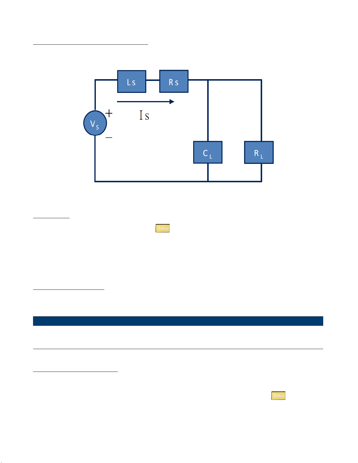
In CZ mode, the electronic load uses an A/D converter to sample and a built-in DSP calculation to simulate the transient
current wave of the tested components. Circuit principle is as follows:
Figure 4.6 Constant Impedance Mode
CZ Ranges
When working in CZ mode, you can Press the the key to enter the RANGE menu. Two overlapping ranges can be
selected: LOW RANGE or HIGH RANGE. Impedance can be edited in either of the two ranges.
Low range will supply higher accuracy and better resolution when you set lower impedance. If any value you set is outside
the maximum value of the LOW RANGE, you should select HIGH RANGE. If the electronic load is in remote control
mode, you can use the IMP:RANG command to switch impedance range.
CZ Vmax/Vmin Limits
These parameters refer to the voltage high and low limit for the automatic test mode. During automatic test mode, the
device under test (DUT) must be operating within the congured values for the test to PASS upon completion. If the
DUT operates outside the congured values, the test will FAIL upon completion.
Note:
These parameters are used for Automatic Test ONLY.
Immediate Impedance level
Set the impedance level via the front panel. If the load is in CZ mode, the new impedance level setting immediately
changes the input. If the load is not in CZ mode, the impedance level setting will be saved for use until mode is switched
to CZ mode. Select the channel to be edited before setting impedance parameters. Press the the
CZ mode. After choosing the high-low range, the front panel will display the following:
button to enter
Page 38
Operations 38
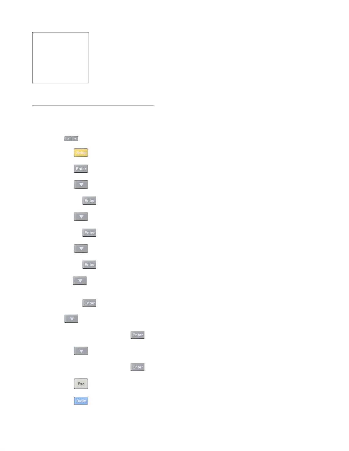
CH01
Rset = 7500.0 Ω
Vmax = 82 V
Vmin = 0 V
RLC R= 7500.0 Ω
RLC L = 0 uH
RLC C = 10 uF
Rset: set the impedance value (𝑅𝐿)
Vmax: set maximum voltage pass/fail limit for Automatic test mode
Vmin: set minimum voltage pass/fail limit for Automatic test mode
RLC R: set the series resistance value (𝑅𝑠)
RLC L: set the series inductance value (𝐿𝑠)
RLC C: set the parallel capacitance value (𝐶𝐿)
4.1.5.1 Setting CV,CC,CR, CW,CZ Mode
To set up an operation mode from the front panel:
1. Power on the electronic load. Self-test
2. Press the
3. Press the the
4. Press the the
5. Press the the
– Press the the
6. Press the the
– Press the the
7. Press the the
– Press the the
8. Press the the
or impedance setting.
keys to select the channel to be edited, such as channel 1. CH01 CC OFF
key to enter the channel setup menu.
key to enter the Mode menu.
key to select CV, CC, CR, CW, or CZ mode.
key to conrm.
key to select the Range menu.
key to conrm
key to select Low Range or High Range.
key to conrm
key to select the voltage setting Vset, current setting Iset, resistance setting Rset, power setting,
– Press the the
9. Press the
– Input the value and Press the the
10. Press the the
– Input the value and Press the the
11. Press the the
12. Press the the
key to select the rise slope setting ∫. Input the value and Press the
key to conrm.
key to select the fall slope setting ∫.
key to exit.
key to turn on the load’s input.
key to conrm. (CC mode only)
key to conrm. (CC mode only)
Page 39
Operations 39
4.2 Local Operations
4.2.1 Mainframe Panel
The front panel keys are eective only in the local mode. When the load is powered on, it works in local mode
automatically (unless any of the remote interfaces are connected to a device controlling it). Select a channel number and
set parameters such as voltage or current via the front panel keys. When the load is repowered on, the mainframe will
scan all the installed modules once again, and can recall the parameters from the last time it was powered o.
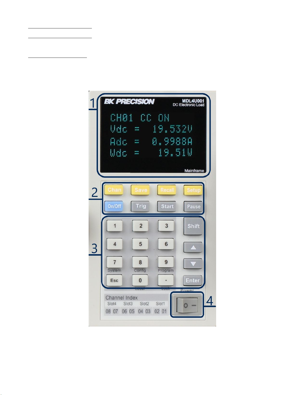
Figure 4.7 MDL4U001 Mainframe Front Panel
1. VFD Display
When powering on, the VFD screen will light up and show the instrument’s rmware version. Then the system will
begin power-on self-test, check all the installed modules of the load, and display every channel’s number, voltage,
and current measurements.
Page 40
Operations 40
2. Function Keys
Key Description
Chan
Save
This key is used to switch channels. Every module has its own channel number and can be selected
from the mainframe panel.
This key is used to save parameters. After selecting a channel and editing its parameters, Press the the
Save key to save your settings into non-volatile memory. Up to 101 groups of parameters can be saved.
Recall This key can be used to quickly recall a saved group of parameters from memory.
This key is used to enter the specic channel’s menu. For example, Press theing this key allows you to
Setup
set up A/B transient mode and CC/CV/CR/CW/CZ mode. For more details, view the Menu List section.
On/O
Trig
This key is used to turn the module’s input state on or o. When the synchronization function in the
channel menu is enabled, Press theing this key can control the on/o state of all channels.
This key is used to trigger the electronic load. Select the Manual Trigger mode to use front panel triggering.
Start This key is used to start an automatic test.
Pause
This key is used to pause an automatic test. The VFD will display pausing at each step. Press the the
key again to test the le continuously.
Table 4.1 Function Keys
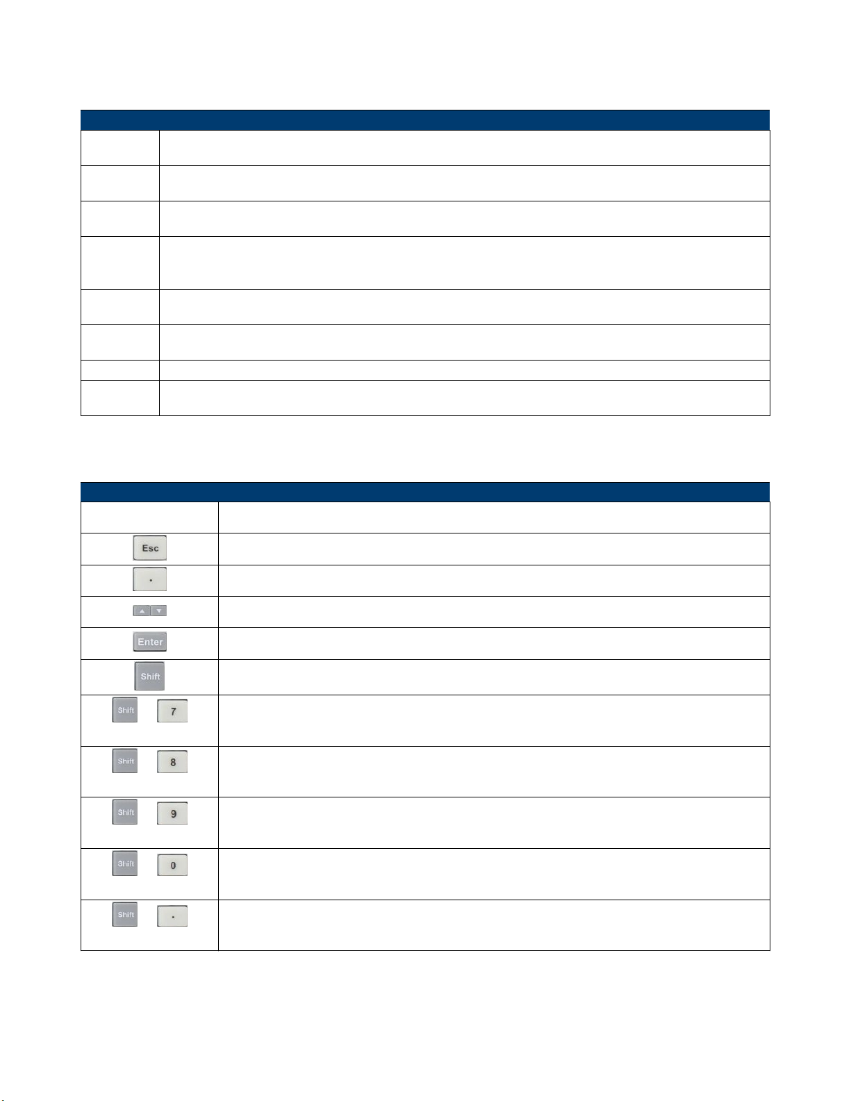
3. Entry/Shift Key
Key Description
Numeric Keys These are number input keys.
This key can be used to exit any working state.
This key is used for decimal.
These keys are used to move up and down the menu selection.
This key is used to conrm selection.
This key is used to enter other menus and functions.
+
Press the this key combination to enter the System menu.
(System)
+
Press the this key combination to enter the Conguration menu.
(Cong)
+
Press the this key combination to enter the Program menu.
(Program)
+
Press the this key to switch the electronic load to local mode when in remote sense mode.
(Local)
+
(Lock)
Press the this key to lock the module’s panel keys and knob. RePress the the button to unlock.
4. Power Switch
Turns the electronic load on or o.
Table 4.2 Entry/Shift Key
Page 41
Operations 41
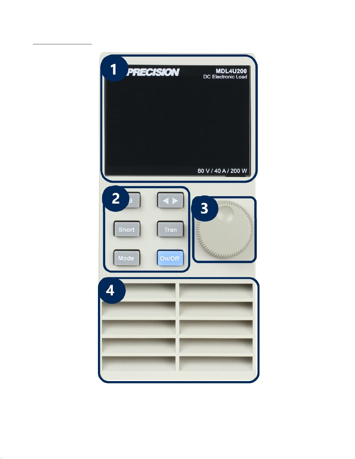
4.2.2 Module Panel
Figure 4.8 Module Front Panel
Page 42
Operations 42
1. VDF Display Bright VFD display shows module‘s operating mode.
2. Panel Keys
Key Description
A/B
(single channel modules)
L/R
(dual-channel modules)
Short Used for short testing. This allows the load to simulate a short circuit at the input.
Mode Switches the operating mode (CC, CR, CV, CW, or CZ).
Tran
On/O Control module’s input on/o state
Switch A/B transient preset value.
Switch the left/right channels. Press the this key + rotary knob to control the two channels.
Move the cursor position. Press the key to move the cursor to the position you want to
edit, and then use the rotary knob to adjust value.
Selects the transient mode. Press the this key rst to enable transient mode before running A/B transient operation and then send the triggering signal to run a program.
Table 4.3 Entry/Shift Key
3. Rotary Knob Used to change parameter values.
4. Air Inlet
Module’s air intlet for cooling purposes.
Warning:
Do not place any objects that may block or cover air inlet.
4.2.3 Module Panel Lock
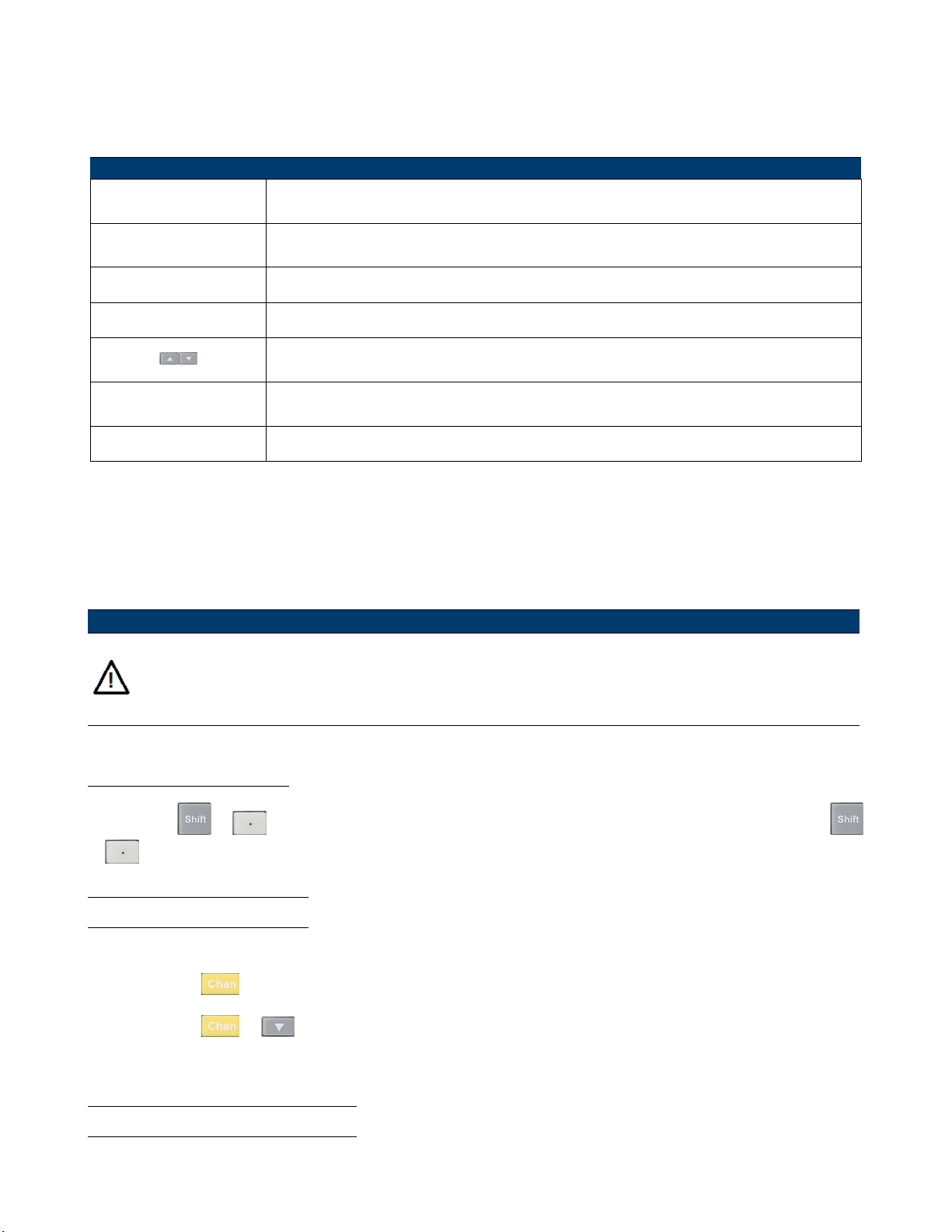
Press the the + keys to lock the selected channel’s keys and knob operation. To unlock, Press the the
+ again.
4.3 Switching Channels
There are three ways to switch channels:
1. Press the the
2. Press the the
3. Press the the number key of the channel in the Setup menu.
+ number keys.
+ keys.
4.4 Channel Synchronization
To change the synchronization of the channels:
Page 43
Operations 43
1. Switch to the channel on the mainframe.
2. Press the
3. Select and enter the SYNC ON SET submenu.
4. Select ON or OFF.
5. When enabled, the
Note:
The same method can be used to set up synchronization with other channels. When in remote control mode, the
SCPI command INPut:ALL ON is used to synchronously load all channels.
+ key to enter the Conguration menu.
key can control the input state of the corresponding module synchronously.
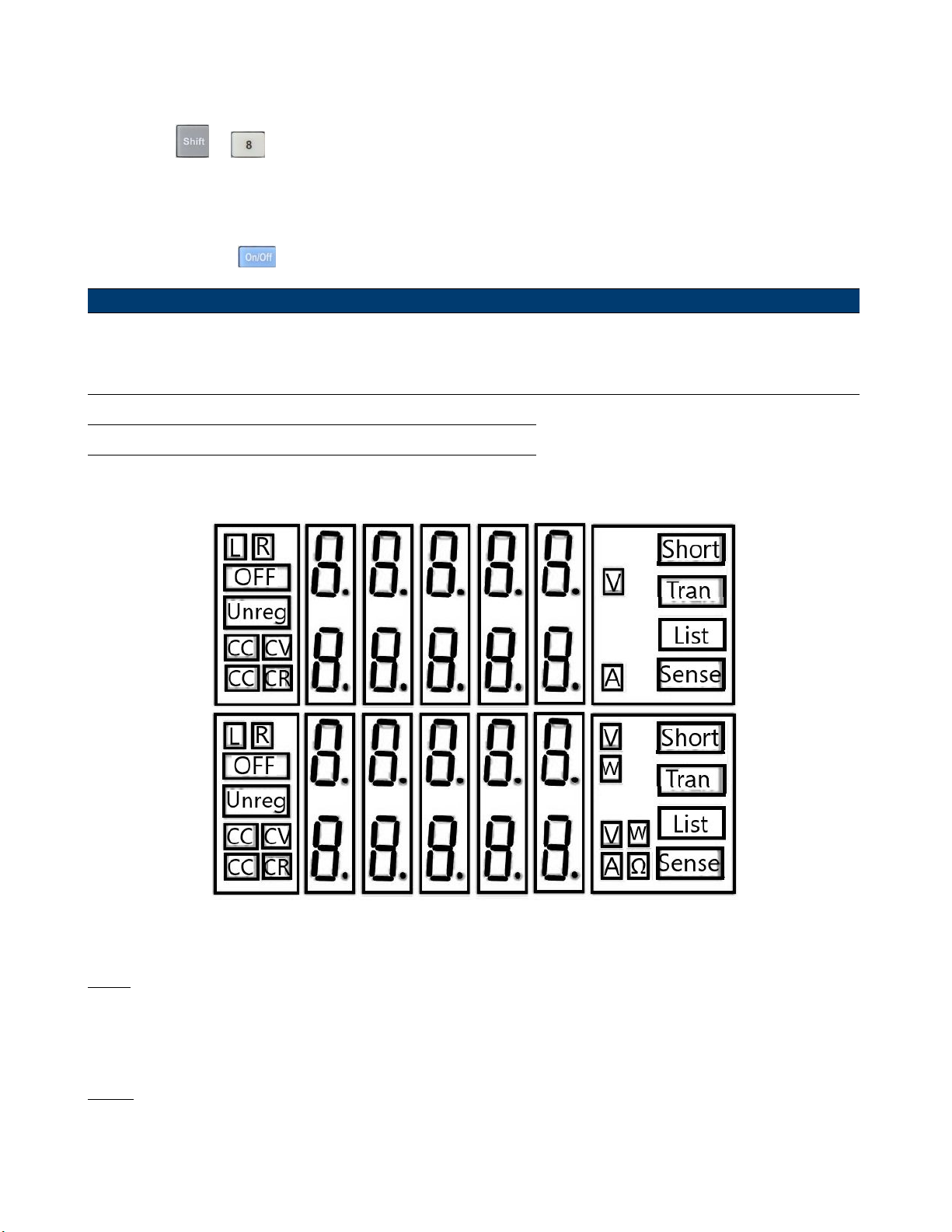
4.5 Module VFD Indicator Function Description
Figure 4.9 indicates
Figure 4.9 Load Module VFD Panel
L/R
The indicator of the dual-channel module’s left/right channel. If you want to edit left/right channel parameters, rst
select the channel using the L/R key. Single-channel module will always display R.
OFF
Indicates that the module input is o. When module input is enabled, OFF indicator will turn o.
Page 44
Operations 44
CC/CV/CR/CW/CZ
Indicates the module’s operating mode.
VFD Display Screen
Shows four lines of numbers. The rst line shows the measured voltage value. The second line shows the measured
current value. The third line shows the measured circuit’s power value. The fourth line shows the setup value, and users
can set A/V/Ω value here.
Short
Is displayed when short circuit function is enabled on the module.
Tran
Is displayed when TRANSIENT mode is enabled on the module.
List
Is displayed when selecting LIST mode in the Conguration menu.
Sense
Is enabled in remote sense function. There is no need to set this in the menu, as you only need to link the circuit to
remote sense terminals and ‘Sense’ will be displayed.
4.6 Transient Operation
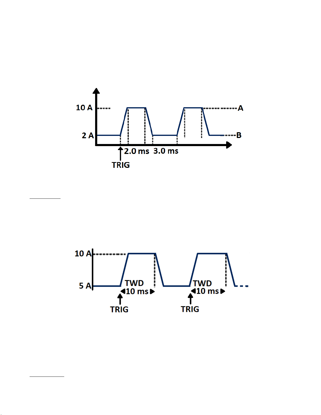
Transient operation enables the module to periodically switch between two load levels, as might be required for testing
power supplies. Transient operation can be turned on and o from the front panel (Tran and Trig keys). The parameters
of the transient operation include: A level, A width, B level, B width, and transient testing modes.
There are three dierent transient testing modes: continuous, pulse, and toggle.
Mode Description
Continuous Generates a respective pulse stream that toggles between two load levels.
Pulse Generates a load change that returns to its original state after some time period.
Generates a repetitive pulse stream that toggles between two load levels. It is similar to con-
Toggle
tinuous mode except that the transient points are controlled by explicit triggers instead of an
internal transient generator.
Table 4.4 Transient Modes
4.6.1 Continuous
The electronic load generates a repetitive pulse stream that toggles between two load levels. The load switches the state
between two value settings, value A and value B.
Page 45
Operations 45
In CC mode, transient testing can be used to check the stability of the source voltage. Transient functions have two
current levels (A level, B level), which should be in the same range (high range or low range). You can set the A/B level
delay time and the rise/fall slew rate via the mainframe keypad.
The slew rate determines the rate at which the level changes. Press the Trig key, and the load will continuously switch
between the A/B levels preset. Transient loads are usually used to test the power supply’s performance under continuous
changing load conditions. Figure
4.10 shows the current waveform of continuous transient operation mode.
Figure 4.10 Continuous Transient Operation
4.6.2 Pulse
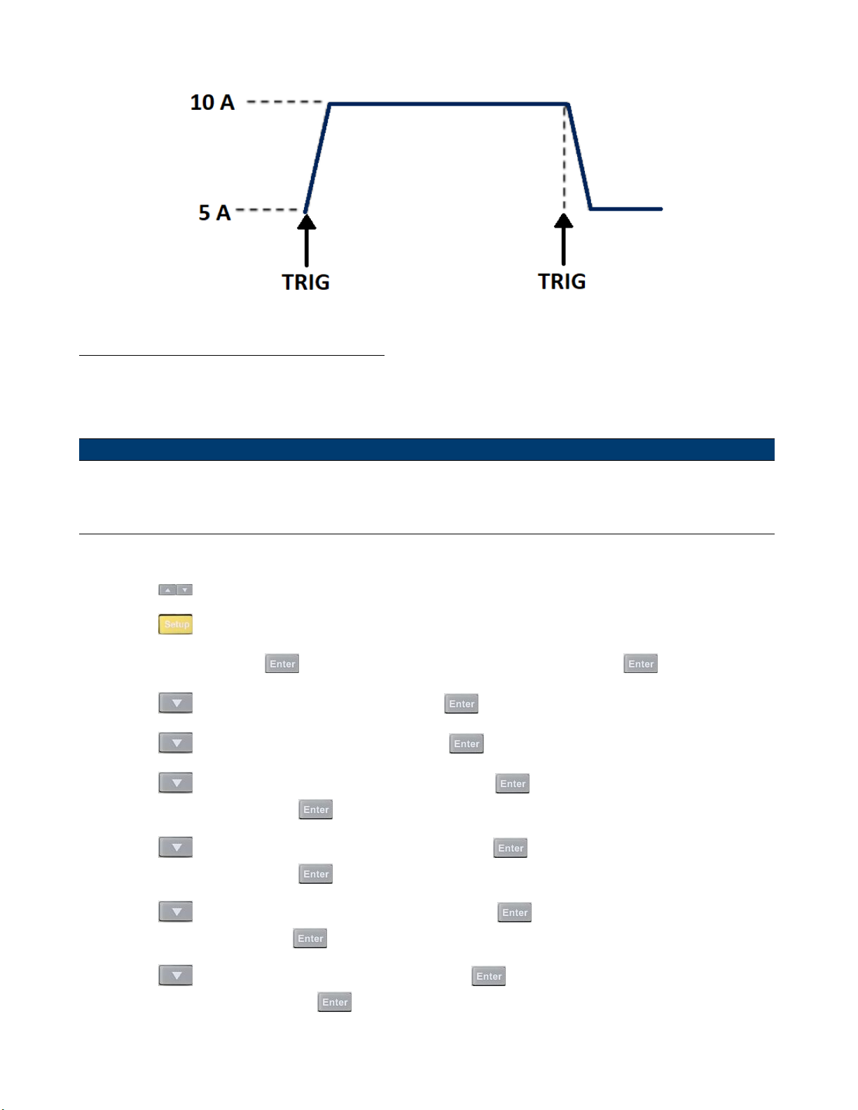
The elctronic load generates a transient pulse of programmable width when pulse transient operation is in eect.
In pulse mode, you can set A/B level, A/B width, and A/B slew rate via the mainframe keypad. The electronic load will
automatically switch to A level after maintaining A width time. Then it will switch to B level. The electronic load will
not switch to A level again until the instrument receives the pulse signal. The gure
in pulse transient operation.
Figure 4.11 Pulse Transient Operation
4.11 shows the current waveform
4.6.3 Toggle
The lectronic load will switch between A level and B level when receiving a trigger signal after the transient operation is
enabled. The following picture shows the current waveform in toggle transient operation.
Page 46
Operations 46
Figure 4.12 Toggle Transient Operation
4.6.4 Setting Up A/B Transient Operation
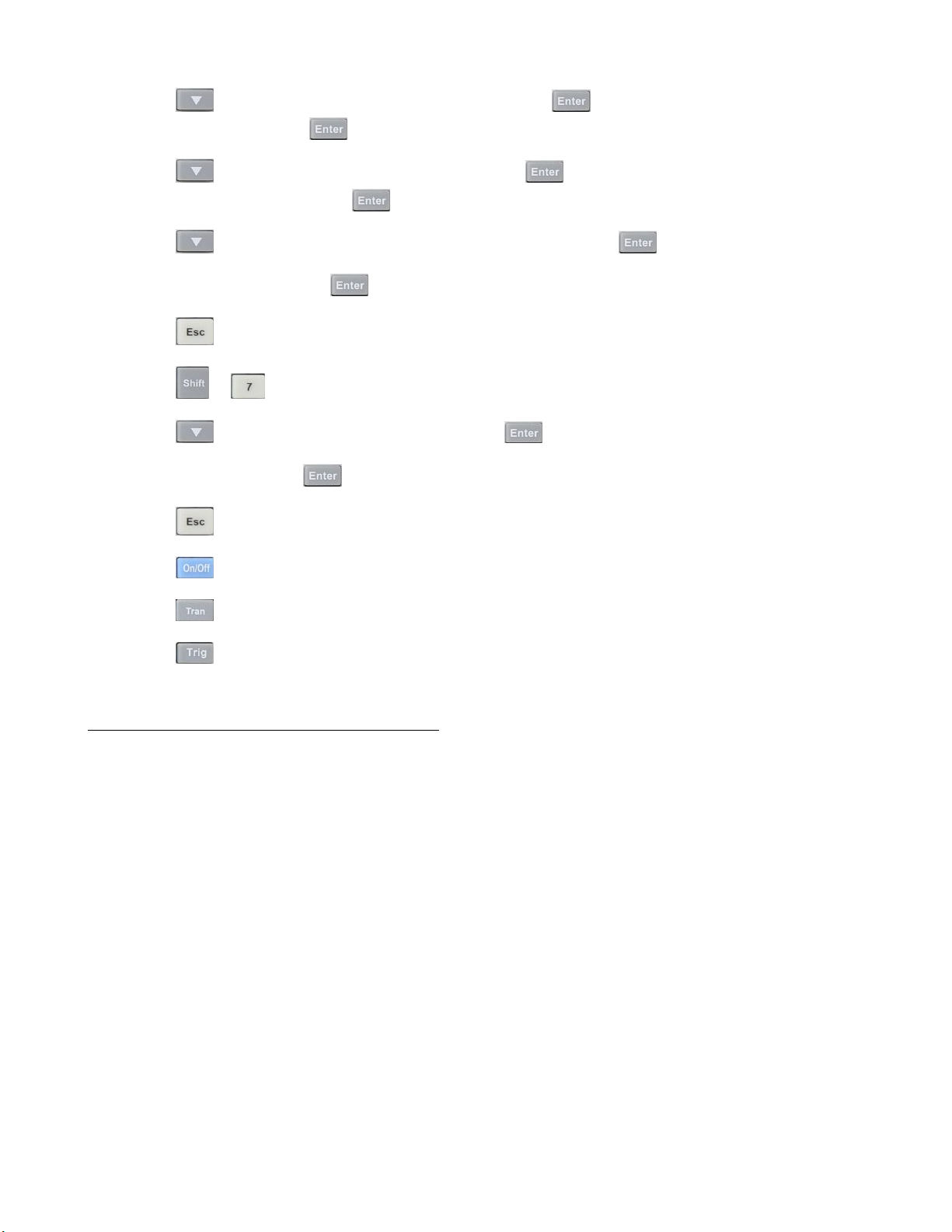
Thee following is a short tutorial of how to set up A/B transient operation for the electronic load. In this example, the
up rise speed at is set to 1 A/us and fall speed at 2 A/us. The electronic load will be in continuous transient mode and
switch between 10 A and 2 A in durations of 0.002 s and 0.003 s respectively.
Note:
When setting up steps, make sure all transient level, slew, and width parameters are within the modules’ specied
limits.
1. Power on the electronic load.
2. Press the
3. Press the
4. Select Mode and Press the
5. Press the
6. Press the
7. Press the
For 1A/us, input 1 and Press the
8. Press the
For 2A/us, input 2 and Press the
keys to select the channel to be edited. In this example, we select channel 1.
to enter the channel setup menu.
to change the operating mode to CC mode. Press the to conrm.
key to select Range setting and press the key.
key to select LOW RANGE and press the key to conrm.
key to select the rise slope setting ∫ and press the .
key to conrm.
key to select the fall slope setting ∫ and press the key.
key to conrm.
9. Press the
For 10A, input 10 and Press the
10. Press the
For 0.002s, input .002 and Press the key to conrm.
key to select A level setting TRANa and press the key.
key to conrm.
key to select A width setting Ta and press the key.
Page 47
Operations 47
11. Press the
For 2A, input 2 and Press the
12. Press the
For 0.003s, input .003 and Press the
13. Press the
14. Select Continuous and press the
15. Press the
16. Press the
17. Press the
18. Select Manual and press the
19. Press the
key to select B level setting TRANb and press the key.
key to select B width setting Tb and press the key.
key to select transient operation mode Tmode and press the key.
key to exit.
+ to enter the System menu.
key to select Trigger Source and press the .
key to exit.
key to conrm.
key to conrm.
key to conrm.
key to conrm.
20. Press the
21. Press the
22. Press the
key to turn on the electronic load’s input.
key on channel 1 module to enable transient operation.
key on mainframe panel to trigger transient operation
Transient Operation Programming Example
In remote mode, the following commands can be used to setup the same parameters used in the tutorial above. (refer
to MDL4U Series Programming Guide for more information).
CURRent:TRANsient:MODE CONTinuous
CURRent:TRANsient:ALEVel 10
CURRent:TRANsient:AWIDth 0.2ms
CURRent:TRANsient:BLEVel 2
CURRent:TRANsient:BWIDth 0.3ms
TRANsient ON
TRIGger:IMMediate
Page 48
Operations 48
4.7 List Operation
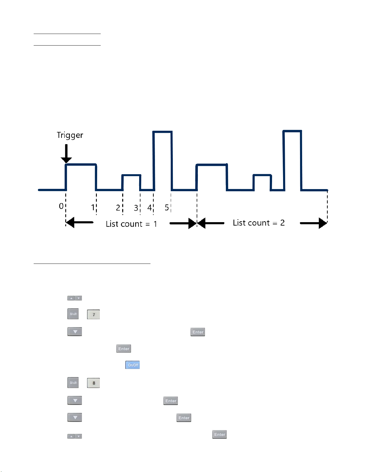
List mode lets you generate complex sequences of input changes on a single channel with rapid and precise timing, which
may be synchronized with internal or external signals. This is useful when running test sequences with a minimum amount
of overhead.
The parameters of List operation include the name, number of steps (2-84), step width time (20 us 3600 s), and every
steps’ set value and slew rate. The list le can be saved in non-volatile memory where it can be quickly recalled. Up to
7 groups of List les in CC mode only can be edited.
In List operation mode, the electronic load begins to enable the List operation when it receives the trigger signal and will
continue until the List operation is completed or the instrument receives another trigger signal
Figure 4.13 List Operation
4.7.1 Setting Up List Operation Mode
The following is a quick tutorial of how to set up List Mode for your electronic load.
1. Power on the electronic load.
2. Press the
3. Press the + to enter the System menu.
4. Press the
5. Select Manual and press the
6. If electronic load is on, press the
7. Press the + to enter the Conguration menu.
8. Press the
keys to select the channel to be edited.
key to select Trigger source and press the key.
key to conrm.
key to turn o the electronic load’s input.
key to select List and press the key.
9. Press the
10. Press the
key to select Edit List and press the key.
key to select high range or low range and press the key to conrm.
Page 49
Operations 49
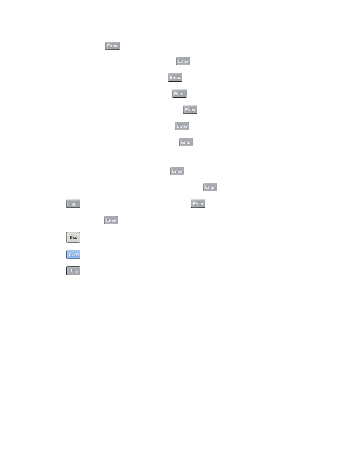
11. Input number of steps in the List.
Input value and press the
12. Set rst step’s current level. Input value and press the key to conrm.
13. Set rst step’s slew rate. Input value and press the
14. Set rst step’s width time. Input value and press the
15. Set second step’s current level. Input value and press the
16. Set second step’s slew rate. Input value and press the
17. Set second step’s width time. Input value and press the
18. Set parameters for steps 3 through 5 in the same manner described above.
19. Set number of run cycles. Input value and press the
20. Select memory position to save list le. Input value and press the
21. Press the
key to select Function Mode and press the .
key to conrm.
key to conrm.
key to conrm.
key to conrm.
key to conrm.
key to conrm.
key to conrm.
key to conrm.
22. Select List and press the
23. Press the
24. Press the
25. Press the
key twice to exit menus.
key to turn on the electronic load’s input.
key to trigger List mode operation.
to conrm.
Page 50

Operations 50
List Mode Programming Example
In remote mode, the following commands can be used to setup the same parameters used in the tutorial above. (refer
to MDL4U Series Programming Guide for more information).
Command
LIST:RANGe
LIST:COUNT
LIST:STEP
LIST:LEVEL
LIST:SLEW
LIST:WIDTH
LIST:LEVEL
LIST:SLEW
LIST:WIDTH
LIST:SAV
LIST:RCL
FUNCTION:MODE LIST
TRIG:SOUR BUS
*TRG
Function
40 Sets List range
10000 Sets List cycle
Sets List steps
Sets List step 1 level
Sets List step 1 slew rate
Sets List step 1 width
Sets List step 2 level
Sets List step 2 slew rate
Sets List step 2 width
Saves List to le 2
Recalls List le 2
Sets List mode function
Sets trigger source
Runs List le
Note:
This example programs a list on a MDL4U200 module. For other models, make sure all range, level, slew, and transient width parameters are within the modules’ specied limits.
Page 51

Operations 51
4.8 Trigger Operation
The trigger operation can be used in the following operations: transient pulse output, triggered output, and list output.
The electronic load has ve kinds of trigger modes to synchronously trigger the tested instrument. Before enabling the
trigger function, the trigger source must be selected.
4.8.1 Manual Trigger
When manual trigger mode is active, pressing the Trig key on the front panel will enable a trigger operation.
4.8.2 External Trigger Signal(TTL level)
The 1𝑠𝑡 pin of the 8-pin connector on the rear panel of the mainframe is the trigger input terminal. When an external
trigger signal is available, input a low pulse (>10us) to the input and the load will enable a trigger operation.
4.8.3 Hold Trigger
When hold trigger is used, the load will enable a trigger operation only when the load receives the TRIG:IMM trigger
command from the communication port.
4.8.4 Bust Trigger
When bus trigger is set, the load will enable a trigger operation as soon as the load receives the trigger command GET
or *TRG.
4.8.5 Timer Trigger
When timer trigger is set, the mainframe will enable a trigger operation periodically.
4.9 Short Operation
The electronic load can simulate a short circuit at its input. During front panel operation, press the key to switch
the short on/o state. Short operation will not aect the present setting. When turning o the short state, the load
returns to the original set state.
The actual value of the electronic load in short operation depends on the mode and range that is active when the short
is turned on. In CC or CR mode, the maximum short current is 120% of the current range. In CV mode, short means
setting the load’s constant voltage to be 0 V. In short operation mode, you can measure the maximum short current
(Amax) or DC current (ADC) of the power source to be measured. This function via the Conguration menu. When in
remote control mode, send the SCPI command INPut:SHORt ON to enable the short operation.
4.10 Input On/O Operation
During front panel operation, press the f key to switch the input on/o state. Input On/O operation will not aect
the present settings. The load/unload speed of On/O operation is not dependent on the rise/fall slew rate. When in
remote control mode, send the SCPI command “INPut ON” to turn the input on (refer to MDL4U Series Programming
Guide for more information on remote commands).
Page 52
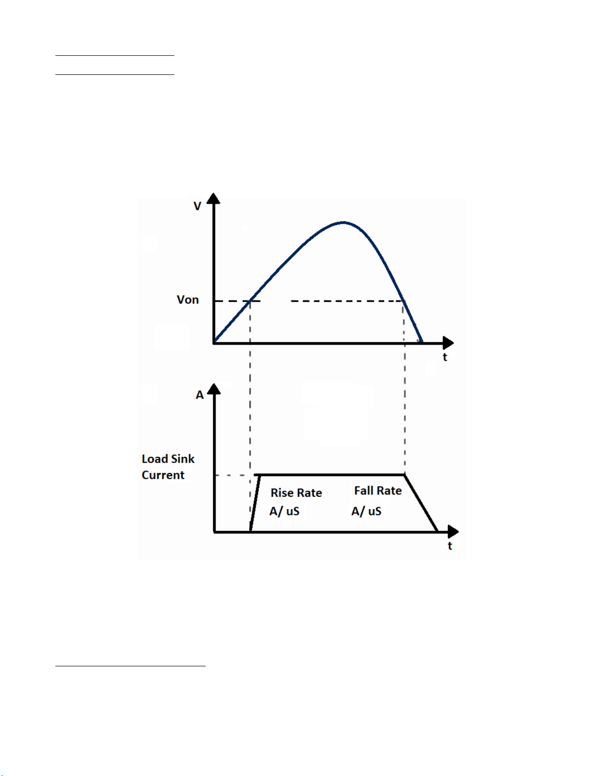
Operations 52
4.11 Von Operation
The Von voltage value can be set to control the voltage turn on state for the electronic load. When the input voltage
exceeds the Von voltage value, the electronic load’s input state turns on.
This function can protect a DUT when its voltage goes below a specied level. For example, when testing a power
supply’s discharge, you can set the voltage level for the power supply to begin and end discharging.
There are two dierent modes of Von operation, set by the Von LATCH parameter. When Von LATCH is disabled, the
electronic load will begin sinking current if input voltage exceeds Von voltage. When the input voltage drops below the
Von voltage value, the electronic load will stop sinking current and the input will turn o.
Figure 4.14 Von LATCH Load’s Working Range
When Von LATCH is enabled, the electronic load will begin sinking current if input voltage exceeds Von voltage. When
the input voltage drops below the Von voltage value, the electronic load will still continue to sink current and the input
remains on.
Setting Up the Von Function
The following is a quick tutorial of how to set up the Von function for your electronic load. In this example, Channel 1
Von is enabled and set to 5 V.
Page 53
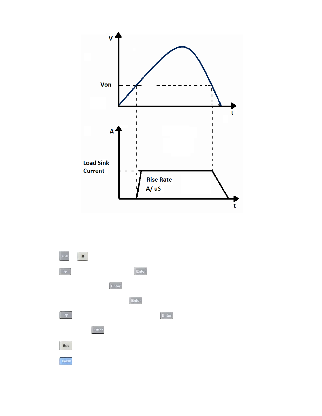
Operations 53
Figure 4.15 Von LATCH Load’s Working Range
1. Power on the electronic load. Self-test
2. Select channel to be set up. Press the 1 for channel 1.
3. Press the
4. Press the
5. Select Von Point and press the
6. Set the Von Point. Input 5 and press the
7. Press the
8. Select On and press the
9. Press the
10. Press the
+ to enter Conguration menu.
to select Von and press the .
key.
to conrm.
key to select Von Latch and press the key.
key to conrm.
key twice to exit menus.
key to turn on the electronic load’s input. The electronic load will begin sinking current at 5 V.
When in remote control mode, you can send SCPI command “VOLT:ON n” to set Von value; send “VOLT:LATch ON”
to enable Von LATCH function.
Page 54
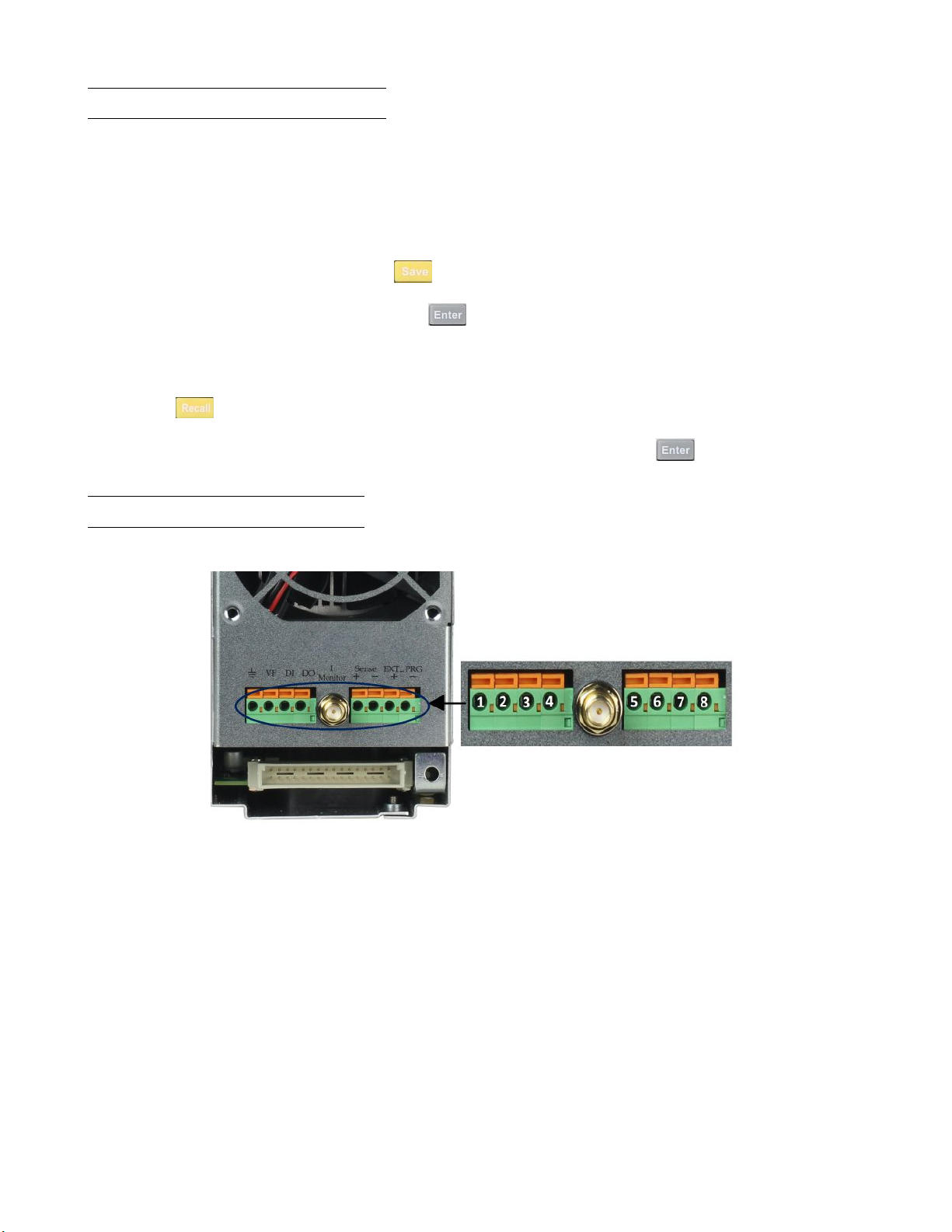
Operations 54
4.12 Save and Recall Operation
The stored settings of all channels can be recalled. The stored parameters include operation mode, voltage/current
values, slew rate, transient setting, and more. Up to 101 groups of setting parameters can be saved. Group 0 can be
used for power-up settings. Groups 1 through 100 can be used for automatic testing parameters. All parameters are
saved into non-volatile memory and will remain saved even in a powered down state.
To save the channel’s settings:
1. After setting up your parameters, press the
2. Input the Save Group number (0-100) and press
To recall previously saved settings:
1. Press the
2. Input the Group number (0-100) you previously saved your parameters to and press
key. It will ask for the Recall Group number.
key to save. It will ask for the Save Group number.
to conrm.
4.13 Module Controlling Link
There is an 8-pin terminal and current monitoring connector on every module’s rear panel.
key to recall.
Figure 4.16 Single-Channel Control Module Link
Page 55
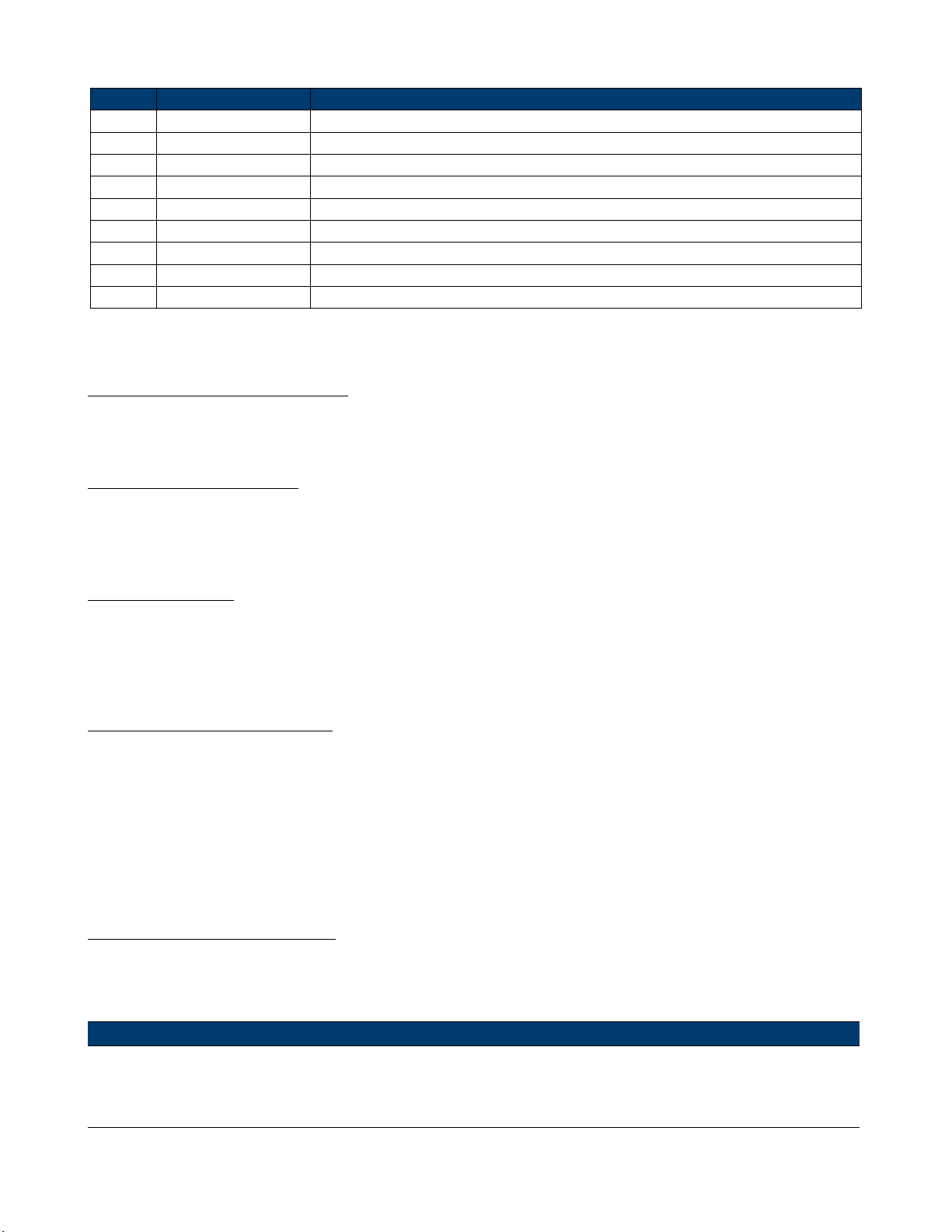
Operations 55
Pin Signal Description
1 GND Ground
2 VF Voltage fault indication terminal
3 DI Digital input terminal
4 DO Digital output terminal
I OUT Current monitoring output
5 SENSE + Voltage remote measuring terminal ( + )
6 SENSE - Voltage remote measuring terminal ( - )
7 EXT_PRG+ External analog controlling terminal ( + )
8 EXT_PRG- External analog controlling terminal ( - )
Table 4.5 Module Terminal Pinout
4.13.1 Voltage Failure Indication
When the electronic load is under OVP or reverse protection condition, pin 2 (VF) will output a high level signal.
4.13.2 Current Monitoring
The current monitoring terminal will output 0-10 V analog signal accordingly to 0 - full range of the input current. You
can connect an external voltmeter or an oscilloscope to display the input current’s change.
4.13.3 Digital I/O
Digital I/O is pin 3 and pin 4 shown in gure 4.16 and only used in remote control. The digital input terminal (pin 3)
can detect a high/low level signal. The digital output terminal (pin 4) can output a TTL high/low level signal. It is a
universal output terminal and can be used to control an external instrument.
4.13.4 Remote Sense Function
When working in CC, CV, and CR mode, if the electronic load consumes a very large current, it will cause a voltage drop
in the leads between the connected device and terminals of the electronic load. In order to ensure testing accuracy, the
electronic load provides a pair of remote sensing terminals in the rear panel where users can sense the output terminal
voltage of the connected device. Set the electronic load to REMOTE SENSE mode before using this function. On the
rear terminals, SENSE (+) and SENSE (–) are the remote sensing inputs. By eliminating the eect of the voltage drop
in the load leads, remote sensing provides greater accuracy by allowing the electronic load to regulate directly at the
source’s output terminals (see Figure
3.1).
4.13.5 External Analog Control
Controls the current setting of the electronic load in CC mode using the external analog programming terminal, pin 7
and pin 8. A 0-10 V input signal will simulate 0 – full scale of the electronic load to regulate the input current of the
electronic load (10 V indicates the full range of electronic load’s current rating)
Note:
External analog control is designed to be used when the instrument is set to High range (full range) only. If low
range is used, the 0-10 V input signal may not reect the full scale input range of the load.
Page 56
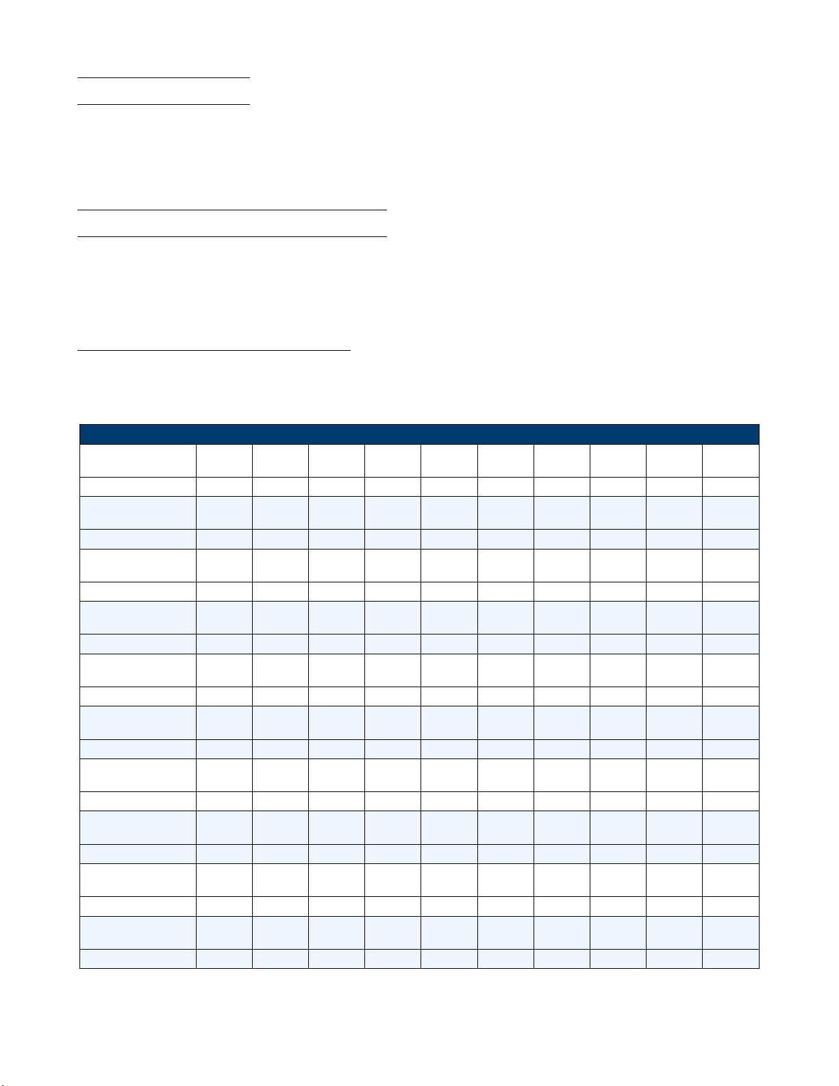
Operations 56
4.14 Automatic Test
The automatic test function of the MDL4U Series electronic load is useful for simulating various tests and allows the
user to edit up to 10 program les. Each le has 10 steps and up to 100 steps can be edited and saved into the
EEPROM. Convenient for production environments, automatic test can cascade sequences across multiple channels and
allows setting of Pass/Fail (P/F) criteria.
4.15 Conguring Pass/Fail Paramters
The Pass/Fail criteria can be found in the SETUP menu of the front panel, under the Vmax/Vmin (CC/CR/CW/CZ
mode) or Amax/Amin (CV mode) parameters. Set Pass/Fail criteria for each mode used in the Automatic test sequence
before running the automated test.
4.15.1 Conguring Instrument Settings
The automatic test runs a program that uses the settings stored into the internal EEPROM memory. Each program can
run 10 sequences, and each of these sequences is correlated to instrument settings that are stored within a designated
group of internal EEPROM memory. They are designated according to the table below:
Save Table
PROGRAM 1
Sequence
Save Group 1 2 3 4 5 6 7 8 9 10
PROGRAM 2
Sequence
Save Group 11 12 13 14 15 16 17 18 19 20
PROGRAM 3
Sequence
Save Group 21 22 23 24 25 26 27 28 29 30
PROGRAM 4
Sequence
Save Group 31 32 33 34 35 36 37 38 39 40
PROGRAM 5
Sequence
Save Group 41 42 43 44 45 46 47 48 49 50
PROGRAM 6
Sequence
Save Group 51 52 53 54 55 56 57 58 59 60
PROGRAM 7
Sequence
Save Group 61 62 63 64 65 66 67 68 69 70
PROGRAM 8
Sequence
Save Group 71 72 73 74 75 76 77 78 79 80
PROGRAM 9
Sequence
Save Group 81 82 83 84 85 86 87 88 89 90
PROGRAM 10
Sequence
Save Group 91 92 93 94 95 96 97 98 99 100
1 2 3 4 5 6 7 8 9 10
1 2 3 4 5 6 7 8 9 10
1 2 3 4 5 6 7 8 9 10
1 2 3 4 5 6 7 8 9 10
1 2 3 4 5 6 7 8 9 10
1 2 3 4 5 6 7 8 9 10
1 2 3 4 5 6 7 8 9 10
1 2 3 4 5 6 7 8 9 10
1 2 3 4 5 6 7 8 9 10
1 2 3 4 5 6 7 8 9 10
Table 4.6 Save Table
The following is a step-by-step tutorial on how to set up a test le
Page 57
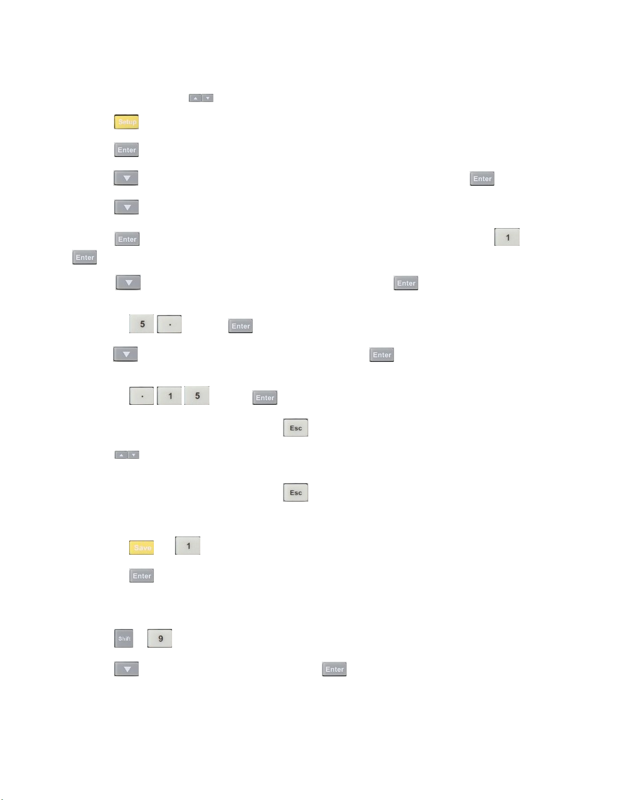
Operations 57
1. Power on the electronic load. Self-test
2. Select the channel you want to edit and then edit every group’s step. For this example, we will select channel 3 and
channel 5 below. Press the keys to switch channel to 3.
3. Press the
4. Press the
5. Press the
6. Press the
7. Press the
key to enter the channel setup menu.
key to enter the Mode menu.
key to select the operating mode. Every step’s mode can be edited. Press the key to conrm.
key to select ISet.
to enter the menu and set the working current. For example, to set 1A, press the and then
to conrm.
8. Press the
key to move the cursor to Vmax=82.000V and press the to set the upper limit of testing
voltage. In this example, the rst step is 5.8V.
– Press the
9. Press the
key to move the cursor to Vmin=0.000V and press the to set the lower limit of testing voltage.
and then to conrm.
In this example, the rst step is 0.15V.
– Press the
and then to conrm.
10. After editing the rst step of channel 3, press the
11. Press the
keys to select channel 5. To edit the rst step of channel 5, repeat steps 3 through 6 with desired
key to exit the menu.
parameters.
12. After editing the rst step of channel 5, press the
key to exit the menu.
13. Save the edited rst step of channel 3 and channel 5.
– Press the
– Press the
and to save step 1.
to conrm.
14. In the same manner, edit the rest of the steps for channel 3 and channel 5 by repeating steps 2 through 10 above.
These saved groups correspond to sequences that will be selected in your program below.
15. Press the
16. Press the
+ key to enter the Program menu.
key to select Edit Program and press the key.
17. The MDL4U Series with mainframe extension can support a maximum of 16 channels. 0 represents the MDL4U001
mainframe and 1 represents the MDL4U002 mainframe extension. 7531 indicates channels 1, 3, 5, and 7 have been
equipped with electronic load modules.
Page 58
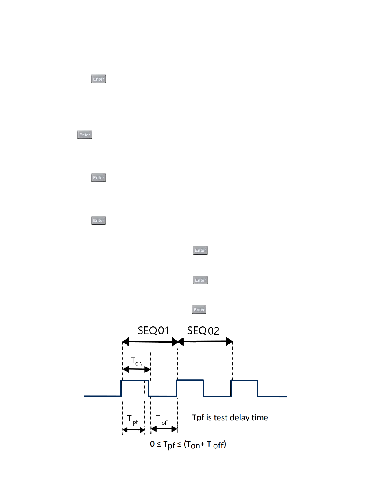
Operations 58
18. Select the channels to be tested.
– For instance, to select channels 3 and 5, press the number keys 3 and 5. ‘Y’ denotes the channel is selected.
– To cancel a channel, press the the number key again to cancel.
– Then press the
19. Select the steps needed to test.
– For example, to test 4 steps, press the 1 2 3 4 (0 stands for the tenth step).
– To cancel a step, press the the number key again to cancel.
– Press the
20. To suspend a step, press the the number key of the step.
– For example, to suspend step 2, press the 2. Press the the number key again to cancel.
– Then press the
21. To edit the rst step of the 4 steps, determine whether a short circuit testing on channel 3 and 5 is needed.
– For example, if channel 3 needs short circuit testing, input 3.
– Then press the
22. Set load on time (Ton).
– For example, if you need 2s, input 2 and then press the
to conrm your selection.
to conrm your selection.
to conrm your selection.
to conrm your selection.
key to conrm.
23. Set load o time (To).
– For example, if you need 2s, input 2 and then press the
24. Set test delay time (Tpf ).
– For example, if 1s is needed, input 1and then press the
key to conrm.
key to conrm.
Figure 4.17 pf Delay Time
Page 59

Operations 59
25. Repeat steps 17 through 20 and set the rest of the steps’ load on/o time.
26. Set condition for when to stop testing.
– COMPLETE means to stop test when all steps are completed.
– FAILURE means to stop test when testing fails.
– Press the
27. Program chain is used when you need to link to the next le to be tested.
– For example, to link to group 2, press the 2.
– If no other le needs to be linked, input
28. Save the edited les into the EEPROM. Up to 10 program les can be saved.
– For instance, press the 1 to save the edited le to program le 1 and then press the
29. Press the
keys to select condition and press the to conrm.
and then press the key to conrm.
key to exit menu.
4.15.2 Recall Test Files
The following is a procedure on how to recall edited test les from the EEPROM:
1. Press
2. Press
+ to enter the Program menu.
key to select Recall Prog and press .
to conrm.
3. Input the saved program number and press
4. To run the program, press
5. Press
– To pause, press
key to start automatic testing.
key to select Run Program and press .
key and then press key to continue.
to recall the saved testing le.
Page 60
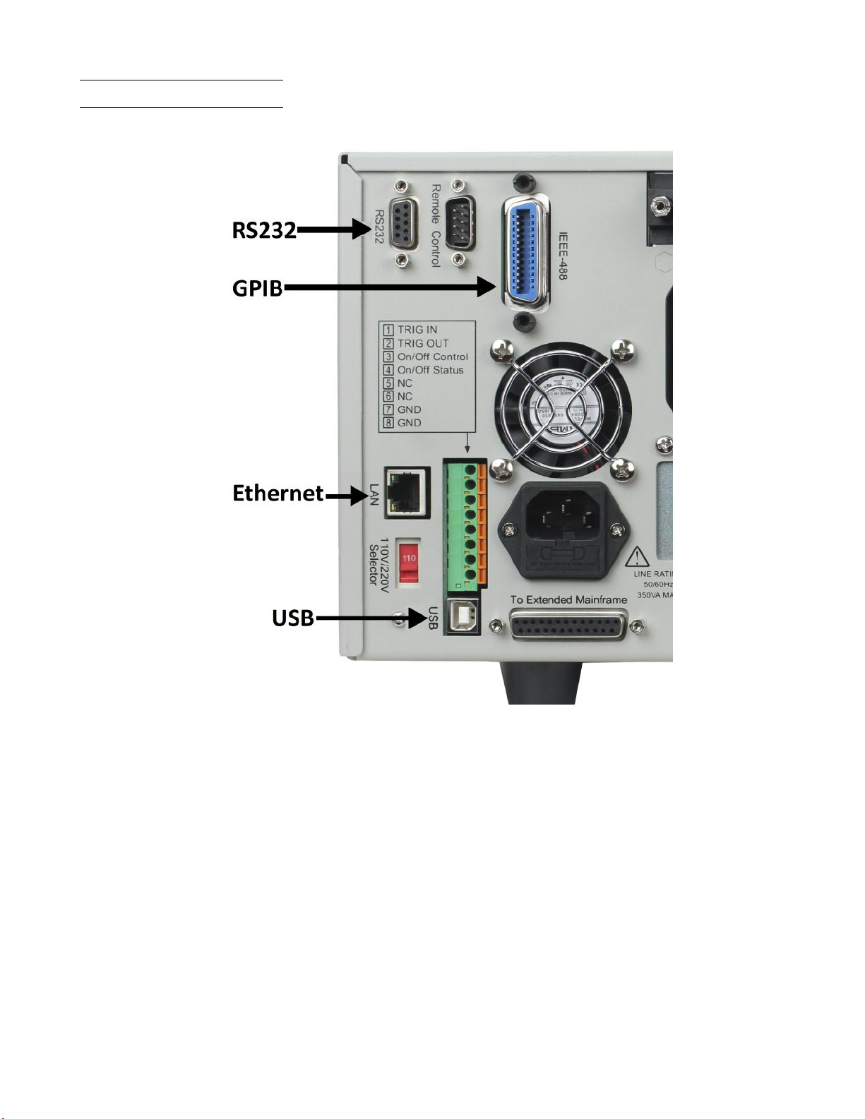
Operations 60
4.16 Remote Operation
There are four types of communication interfaces available: USB, Ethernet, GPIB, and RS232.
Figure 4.18 Communication Interfaces
Page 61
Operations 61
4.16.1 USB Interface
Use Type A to Type B USB cables to connect the electronic load and the PC. All electronic load functions are program-
mable over the USB. Press
choose USBTMC-USB488.
The USB488 interface capabilities of the electronic load are described below:
• The interface is IEEE 488.2 standard USB488 interface.
• The interface accepts REN_CONTROL, GO_TO_LOCAL, and LOCAL_LOCKOUT requests.
• The interface accepts MsgID = TRIGGER USBTMC command message and forwards TRIGGER requests to the
function layer.
The USB488 device capabilities of the electronic load are described below:
• The device understands all mandatory SCPI commands.
• The device is SR1 capable.
• The device is RL1 capable.
• The device is DT1 capable.
+ on the front panel to enter the System menu. Select Communication and
4.16.2 Ethernet Interface
Use a network cable to connect PC through Ethernet interface of the electronic load. Press + on the front
panel to enter the System menu. Select Communication and choose ETHERNET. Then select Ethernet Set to set
gateway address Gateway Set, IP address IP Set, mask address Mask set, and port port set.
4.16.3 GPIB Interface
First connect GPIB port of electronic load to GPIB card of PC. There must be sucient contact. Tighten the screws
and then set the address. The address can be set from 0 to 31. Press
Select Communication and choose GPIB. The electronic load operates from a GPIB address set from the front panel.
To set the GPIB address, press
The GPIB address is stored in non-volatile memory.
key to select GPIB Address. Input the address and press key to conrm.
+ key to enter the System menu.
RS232 Interface
Use a cable with two COM interfaces (DB9) to connect the electronic load and PC. It can be activated by selecting
RS-232 in Communication of the System menu.
Note:
There are two COM interfaces on the rear panel of the MDL4U001 mainframe: the left 9-pin COM interface is the
RS-232 communication interface and the right 9-pin COM serial port connection is not for use.
Page 62
Operations 62
All SCPI commands are available through RS-232 programming. The EIA RS-232 standard denes the interconnections
between data terminal equipment (DTE) and data communications equipment (DCE). The electronic load is designed
to be a DTE and can be connected to another DTE such as a PC COM port through a null modem cable.
Note:
The RS-232 settings in your program must match the settings specied in the front panel System menu. Press
+ on the front panel to enter the System menu if you need to change the settings.
RS232 Data Format
The RS-232 data is a 10-bit word with one start bit and one stop bit.
Parity = None
The number of start and stop bits are not programmable. However, the following parameters are selectable in the System
menu using the front panel
+ key.
Start Bit
8 Data Bits
Stop Bits
Baud Rate
The System menu lets you select one of the following baud rates, which are stored in non-volatile memory: 4800, 9600,
19200, 38400, 57600, or 115200.
Parity
None - eight data bits without parity
Even - seven data bits with even parity
Odd - seven data bits with odd parity
RS232 Flow Control
The RS232 interface supports the following ow control options. For each case, the electronic load will send a maximum
of ve characters after hold-o is asserted by the controller. The electronic load is capable of receiving as many as fteen
additional characters after it asserts hold-o.
• CTS/RTS: The electronic load asserts its Request to Send (RTS) line to signal hold-o when its input buer is
almost full, and it interprets its Clear to Send (CTS) line as a hold-o signal from the controller.
• XON/XOFF: When the input queue of the electronic load becomes more than ¾ full, the instrument issues an X-OFF
command. The control program should respond to this and stop sending characters until the electronic load issues
the X-ON, which it will do once its input buer has dropped below half-full. The electronic load recognizes X_ON
and X_OFF sent from the controller. An X-OFF will cause the electronic load to stop outputting characters until it
sees an X-ON.
• NONE: No ow control.
Flow control options are stored in non-volatile memory.
Page 63
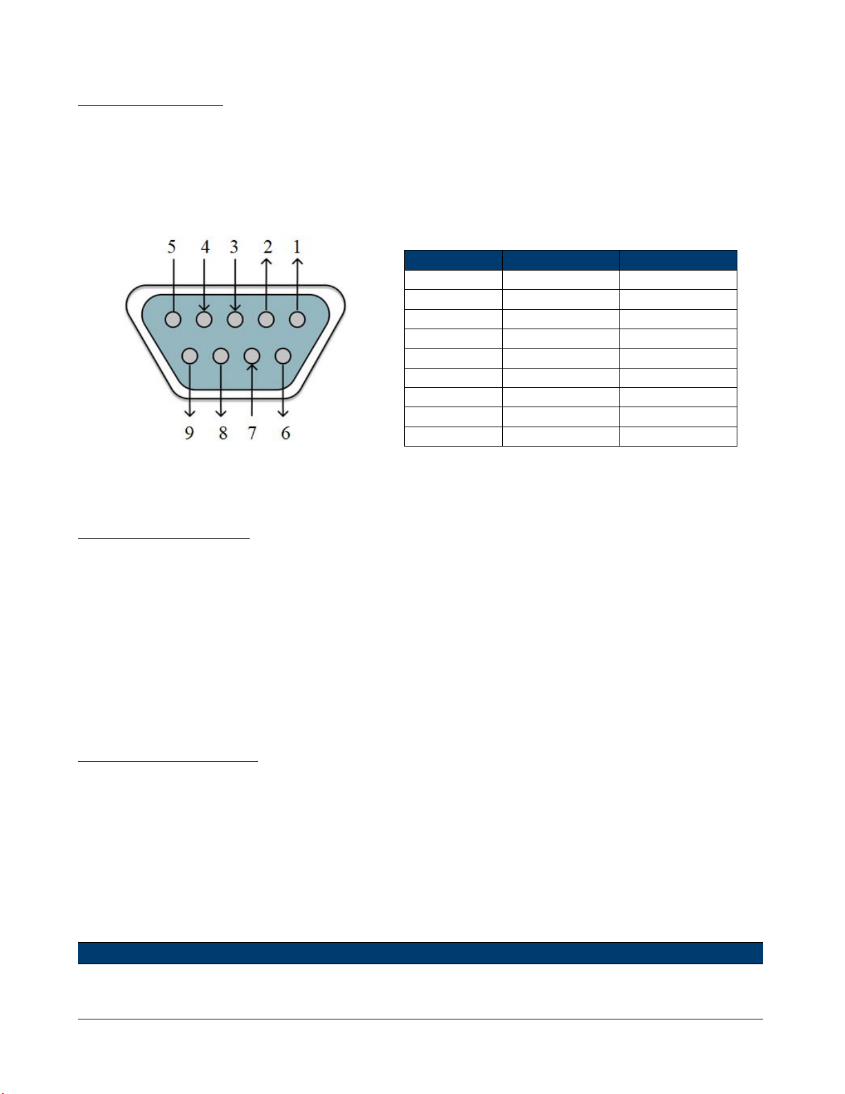
Operations 63
RS232 Connections
The RS-232 serial port can be connected to the serial port of a controller (i.e., personal computer) using a straightthrough RS-232 cable terminated with DB-9 connectors. Do not use a null modem cable. Figure 33 shows the pinout
for the connector.
If your computer uses a DB-25 connector for the RS-232 interface, you will need a cable or adapter with a DB-25
connector on one end and a DB-9 connector on the other. It must be a straightthrough (not null modem) a cable.
Pin Number Signal Function
1 NC No Connection
2 TXD Transmit Data
3 RXD Receive Data
4 NC No Connection
5 GND Ground
6 NC No Connection
7 CTS Clear to Send
8 RTS Ready to Send
9 NC No Connection
Figure 4.19 DB9 Pinout
Table 4.7 DB9 Pinout
RS232 Troubleshooting
If you are having trouble communicating over the RS-232 interface, check the following:
• The computer and the electronic load must be congured for the same baud rate, parity, number of data bits, and
ow control options. Note that the electronic load is congured for 1 start bit and 1 stop bit (these values are xed).
• The correct interface cables or adapters must be used, as described under the RS-232 connector. Note that even if
the cable has the proper connectors for your system, the internal wiring may be incorrect.
• The interface cable must be connected to the correct serial port on your computer (COM1, COM2, etc.) and the
correct 9-pin serial port on the mainframe.
Communication Settings
Before communicating, please make sure that the following parameters of the electronic load match that of the PC. You
can enter the System menu (Shift + ) to make any changes.
Baud rate : 9600 (5800, 9600, 19200, 38400, 57600, 115200)
Data bit : 8
Stop bit : 1
Parity : None (None, Even, Odd)
Local address : 0 (0 through 31, default setting is 0)
Note:
When communicating with a PC, you can only use one communication interface at a time.
Page 64
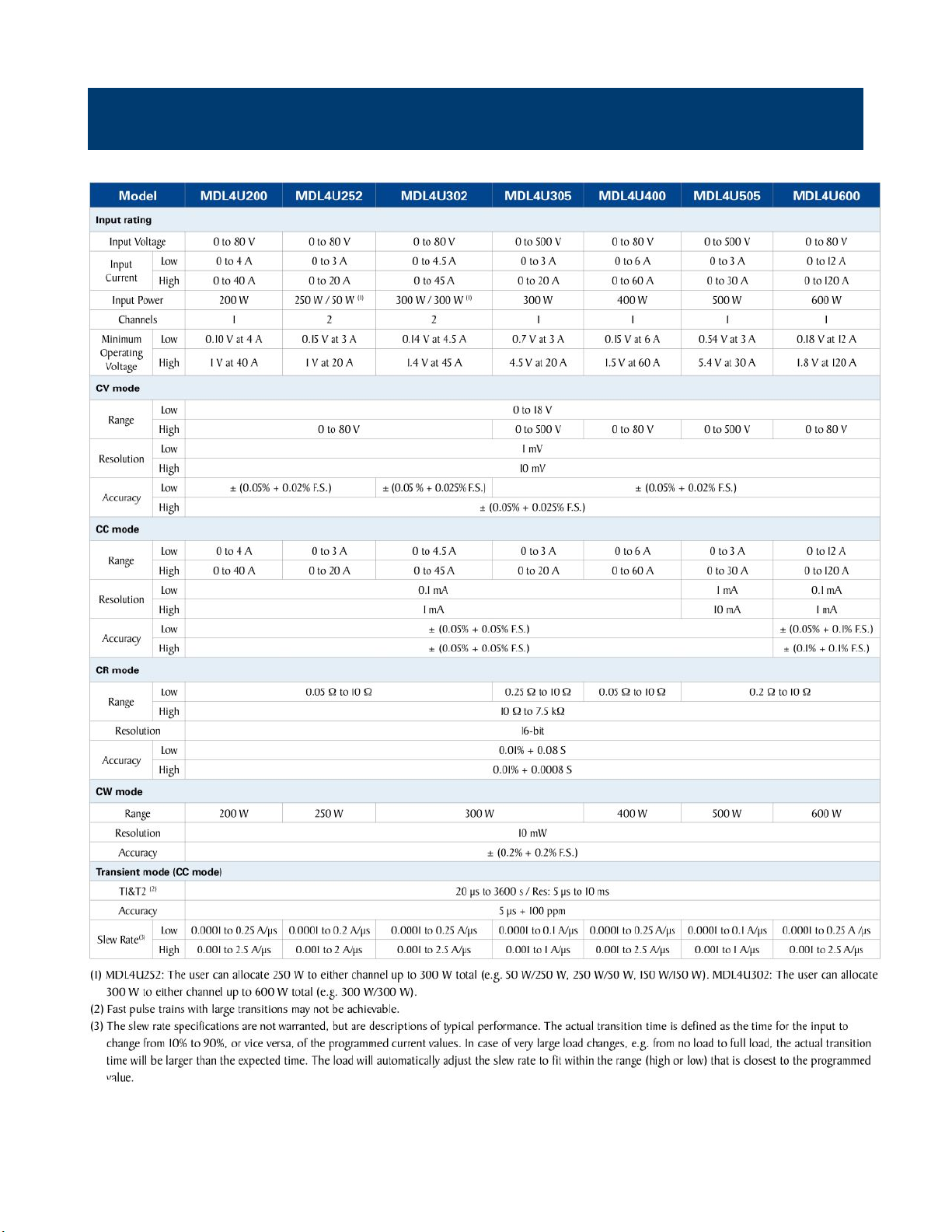
Specications
Page 65
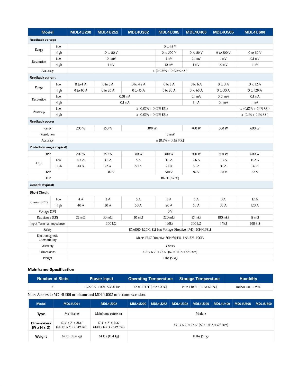
Specications 65
Page 66

Service Information
Warranty Service: Please go to the support and service section on our website at bkprecision.com to obtain an RMA
#. Return the product in the original packaging with proof of purchase to the address below. Clearly state on the RMA
the performance problem and return any leads, probes, connectors and accessories that you are using with the device.
Non-Warranty Service: Please go to the support and service section on our website at bkprecision.com to obtain an
RMA #. Return the product in the original packaging to the address below. Clearly state on the RMA the performance
problem and return any leads, probes, connectors and accessories that you are using with the device. Customers not on
an open account must include payment in the form of a money order or credit card. For the most current repair charges
please refer to the service and support section on our website.
Return all merchandise to B&K Precision Corp. with prepaid shipping. The at-rate repair charge for Non-Warranty
Service does not include return shipping. Return shipping to locations in North America is included for Warranty Service.
For overnight shipments and non-North American shipping fees please contact B&K Precision Corp.
Include with the returned instrument your complete return shipping address, contact name, phone number and description
of problem.
B&K Precision Corp.
22820 Savi Ranch Parkway
Yorba Linda, CA 92887
bkprecision.com
714-921-9095
Page 67

LIMITED THREE-YEAR WARRANTY
B&K Precision Corp. warrants to the original purchaser that its products and the component parts thereof, will be free
from defects in workmanship and materials for a period of three years from date of purchase.
B&K Precision Corp. will, without charge, repair or replace, at its option, defective product or component parts. Returned
product must be accompanied by proof of the purchase date in the form of a sales receipt.
To help us better serve you, please complete the warranty registration for your new instrument via our website www.bkprecision.com
Exclusions: This warranty does not apply in the event of misuse or abuse of the product or as a result of
unauthorized alterations or repairs. The warranty is void if the serial number is altered, defaced or removed.
B&K Precision Corp. shall not be liable for any consequential damages, including without limitation damages resulting
from loss of use. Some states do not allow limitations of incidental or consequential damages. So the above limitation
or exclusion may not apply to you.
This warranty gives you specic rights and you may have other rights, which vary from state-to-state.
B&K Precision Corp.
22820 Savi Ranch Parkway
Yorba Linda, CA 92887
bkprecision.com
714-921-9095
Page 68

Error Messages 90
22820 Savi Ranch Parkway
Yorba Linda, CA 92887
www.bkprecision.com
© 2021 B&K Precision Corp.
Version: August 5, 2021
 Loading...