

Page 1

Page 2

2
SafetySummary
Thefollowingsafetyprecautionsapplytobothoperatingandmaintenancepersonnelandmustbefollowed
duringallphasesofoperation,service,andrepairofthisinstrument.
Beforeapplyingpowertothisinstrument:
•Readandunderstandthesafetyandoperationalinformationinthismanual.
•Applyallthelistedsafetyprecautions.
•Verifythatthevoltageselectoratthelinepowercordinputissettothecorrectlinevoltage.Operating
theinstrumentatanincorrectlinevoltagewillvoidthewarranty.
•Makeallconnectionstotheinstrumentbeforeapplyingpower.
•DonotoperatetheinstrumentinwaysnotspeciedbythismanualorbyB&KPrecision.
Failuretocomplywiththeseprecautionsorwithwarningselsewhereinthismanualviolatesthesafety
standardsofdesign,manufacture,andintendeduseoftheinstrument.B&KPrecisionassumesno
liabilityforacustomer’sfailuretocomplywiththeserequirements.
Categoryrating
TheIEC61010standarddenessafetycategoryratingsthatspecifytheamountofelectricalenergy
availableandthevoltageimpulsesthatmayoccuronelectricalconductorsassociatedwiththesecategory
ratings.ThecategoryratingisaRomannumeralofI,II,III,orIV.Thisratingisalsoaccompaniedbya
maximumvoltageofthecircuittobetested,whichdenesthevoltageimpulsesexpectedandrequired
insulationclearances.Thesecategoriesare:
CategoryI(CATI):Measurementinstrumentswhosemeasurementinputsarenotintendedtobe
connectedtothemainssupply.Thevoltagesintheenvironmentaretypically
derivedfromalimited-energytransformerorabattery.
CategoryII(CATII):Measurementinstrumentswhosemeasurementinputsaremeanttobeconnected
tothemainssupplyatastandardwalloutletorsimilarsources. Example
measurementenvironmentsareportabletoolsandhouseholdappliances.
CategoryIII(CATIII):Measurementinstrumentswhosemeasurementinputsaremeanttobe
connectedtothemainsinstallationofabuilding. Examplesaremeasurements
insideabuilding’scircuitbreakerpanelorthewiringofpermanently-installedmotors.
Page 3

3
CategoryIV(CATIV):Measurementinstrumentswhosemeasurementinputsaremeanttobe
connectedtotheprimarypowerenteringabuildingorotheroutdoorwiring.
Donotusethisinstrumentinanelectricalenvironmentwithahighercategoryratingthanwhatisspecied
inthismanualforthisinstrument.
Youmustensurethateachaccessoryyouusewiththisinstrumenthasacategoryratingequaltoor
higherthantheinstrument’scategoryratingtomaintaintheinstrument’scategoryrating. Failuretodo
sowilllowerthecategoryratingofthemeasuringsystem.
ElectricalPower
ThisinstrumentisintendedtobepoweredfromaCATEGORYIImainspowerenvironment.Themains
powershouldbe115VRMSor230VRMS.Useonlythepowercordsuppliedwiththeinstrumentand
ensureitisappropriateforyourcountryofuse.
GroundtheInstrument
Tominimizeshockhazard,theinstrumentchassisandcabinetmustbeconnectedtoanelectricalsafety
ground.Thisinstrumentisgroundedthroughthegroundconductorofthesupplied,three-conductorAC
linepowercable.Thepowercablemustbepluggedintoanapprovedthree-conductorelectricaloutlet.
ThepowerjackandmatingplugofthepowercablemeetIECsafetystandards.
Donotalterordefeatthegroundconnection.Withoutthesafetygroundconnection,allaccessible
conductiveparts(includingcontrolknobs)mayprovideanelectricshock.Failuretouseaproperly-
groundedapprovedoutletandtherecommendedthree-conductorAClinepowercablemayresultin
injuryordeath.
Page 4

4
Unlessotherwisestated,agroundconnectionontheinstrument’sfrontorrearpanelisforareference
ofpotentialonlyandisnottobeusedasasafetyground.Donotoperateinanexplosiveorammable
atmosphere.
Donotoperatetheinstrumentinthepresenceofammablegasesorvapors,fumes,ornely-divided
particulates.
Theinstrumentisdesignedtobeusedinoce-typeindoorenvironments.Donotoperatetheinstrument
•Inthepresenceofnoxious,corrosive,orammablefumes,gases,vapors,chemicals,ornely-divided
particulates.
•Inrelativehumidityconditionsoutsidetheinstrument’sspecications.
•Inenvironmentswherethereisadangerofanyliquidbeingspilledontheinstrumentorwhereany
liquidcancondenseontheinstrument.
•Inairtemperaturesexceedingthespeciedoperatingtemperatures.
•Inatmosphericpressuresoutsidethespeciedaltitudelimitsorwherethesurroundinggasisnotair.
•Inenvironmentswithrestrictedcoolingairow,eveniftheairtemperaturesarewithinspecications.
•Indirectsunlight.
Thisinstrumentisintendedtobeusedinanindoorpollutiondegree2environment.Theoperating
temperaturerangeis0∘Cto40∘Cand20%to80%relativehumidity,withnocondensationallowed.
Measurementsmadebythisinstrumentmaybeoutsidespecicationsiftheinstrumentisusedinnon-
oce-typeenvironments.Suchenvironmentsmayincluderapidtemperatureorhumiditychanges,sunlight,
vibrationand/ormechanicalshocks,acousticnoise,electricalnoise,strongelectricelds, orstrong
magneticelds.
Donotoperateinstrumentifdamaged
Iftheinstrumentisdamaged,appearstobedamaged,orifanyliquid,chemical,orothermaterialgetson
orinsidetheinstrument,removetheinstrument’spowercord,removetheinstrumentfromservice,label
Page 5

5
itasnottobeoperated,andreturntheinstrumenttoB&KPrecisionforrepair.NotifyB&KPrecisionof
thenatureofanycontaminationoftheinstrument.
Cleantheinstrumentonlyasinstructed
Donotcleantheinstrument,itsswitches,oritsterminalswithcontactcleaners,abrasives,lubricants,
solvents,acids/bases,orothersuchchemicals.Cleantheinstrumentonlywithacleandrylint-freecloth
orasinstructedinthismanual.Notforcriticalapplications
Thisinstrumentisnotauthorizedforuseincontactwiththehumanbodyorforuseasacomponentina
life-supportdeviceorsystem.
Donottouchlivecircuits
Instrumentcoversmustnotberemovedbyoperatingpersonnel.Componentreplacementandinternal
adjustmentsmustbemadebyqualiedservice-trainedmaintenancepersonnelwhoareawareofthe
hazardsinvolvedwhentheinstrument’scoversandshieldsareremoved.Undercertainconditions,
evenwiththepowercordremoved,dangerousvoltagesmayexistwhenthecoversareremoved. To
avoidinjuries,alwaysdisconnectthepowercordfromtheinstrument,disconnectallotherconnections
(forexample,testleads,computerinterfacecables,etc.),dischargeallcircuits,andverifythereare
nohazardousvoltagespresentonanyconductorsbymeasurementswithaproperly-operatingvoltage-
sensingdevicebeforetouchinganyinternalparts.Verifythevoltage-sensingdeviceisworkingproperly
beforeandaftermakingthemeasurementsbytestingwithknown-operatingvoltagesourcesandtestfor
bothDCandACvoltages.Donotattemptanyserviceoradjustmentunlessanotherpersoncapableof
renderingrstaidandresuscitationispresent.
Donotinsertanyobjectintoaninstrument’sventilationopeningsorotheropenings.
Hazardousvoltagesmaybepresentinunexpectedlocationsincircuitrybeingtestedwhenafaultcondition
inthecircuitexists.
Fusereplacementmustbedonebyqualiedservice-trainedmaintenancepersonnelwhoareawareof
theinstrument’sfuserequirementsandsafereplacementprocedures. Disconnecttheinstrumentfrom
Page 6

6
thepowerlinebeforereplacingfuses.Replacefusesonlywithnewfusesofthefusetypes,voltage
ratings,andcurrentratingsspeciedinthismanualoronthebackoftheinstrument. Failuretodoso
maydamagetheinstrument,leadtoasafetyhazard,orcauseare.Failuretousethespeciedfuses
willvoidthewarranty.
Servicing
DonotsubstitutepartsthatarenotapprovedbyB&KPrecisionormodifythisinstrument.Returnthe
instrumenttoB&KPrecisionforserviceandrepairtoensurethatsafetyandperformancefeaturesare
maintained.
Forcontinuedsafeuseoftheinstrument
•Donotplaceheavyobjectsontheinstrument.
•Donotobstructcoolingairowtotheinstrument.
•Donotplaceahotsolderingironontheinstrument.
•Donotpulltheinstrumentwiththepowercord,connectedprobe,orconnectedtestlead.
•Donotmovetheinstrumentwhenaprobeisconnectedtoacircuitbeingtested.
ComplianceStatements
DisposalofOldElectrical&ElectronicEquipment(ApplicableintheEuropeanUnionandother
Europeancountrieswithseparatecollectionsystems)
ThisproductissubjecttoDirective2002/96/ECoftheEuropean
ParliamentandtheCounciloftheEuropeanUniononwasteelectrical
andelectronicequipment(WEEE),andinjurisdictionsadoptingthat
Directive,ismarkedasbeingputonthemarketafterAugust13,2005,
andshouldnotbedisposedofasunsortedmunicipalwaste. Please
utilizeyourlocalWEEEcollectionfacilitiesinthedispositionofthis
productandotherwiseobserveallapplicablerequirements.
Page 7

SafetySymbols
SymbolDescription
Indicatesahazardoussituationwhich,ifnotavoided,willresultindeathor
seriousinjury.
Indicatesahazardoussituationwhich,ifnotavoided,couldresultindeathor
seriousinjury.
Indicatesahazardoussituationwhich,ifnotavoided,willresultinminoror
moderateinjury.
Refertothetextnearthesymbol.
ElectricShockhazard
Alternatingcurrent(AC)
7
Chassisground
Earthground
IndicatestheInpositionofthepowerswitchwheninstrumentisON.
IndicatestheOutpositionofthepowerswitchwheninstrumentisOFF.
Indicatespracticesnotrelatedtophysicalinjury.
Table1SafetySymbols
Page 8

Contents
1Introduction11
1.1ProductOverview11
1.2Contents12
1.3Features12
1.4Dimensions13
1.5FrontPanel14
1.6RearPanel15
2GettingStarted16
2.1InputPowerandFuseRequirements16
2.2FuseRequirements17
2.3CheckorReplaceFuse17
3BasicFrontPanelOperations19
3.1Keys19
3.1.1FunctionKeys19
3.1.2Softkeys20
3.1.3NumericKeypad20
3.1.4NavigationKeys21
3.2Display22
3.2.1Menu22
4Source23
4.1SourceParameters23
4.2Output24
4.2.1Channel24
4.2.2OutputParameters24
4.3View25
4.3.1Measure26
4.4Graph28
4.5Save28
4.6Recall29
4.7ProtClr29
5Cong30
5.1Cong130
5.1.1OutputSpeed31
5.1.2VoltageRange32
5.1.3CurrentSense33
5.1.4OverVoltageProtection34
Page 9

9
5.1.5VoltageLimit35
5.1.6CurrentLimit36
5.1.7OutputDelay37
5.2Conf238
5.2.1Output-oState39
5.2.2OverCurrentProtection40
5.2.3TraceState41
5.2.4TriggerMode42
5.2.5Ext_ON/OFFMode43
5.2.6Ext_ON/OFFState44
5.2.7DigitalFunction45
5.3Conf346
5.3.1CurrentLowRange47
6Graph48
6.1Channel49
6.2Scope49
6.3Knob50
6.4TrigSet51
6.5Auto52
6.6V_Range52
6.7I_Range53
6.8Run/Hold54
7Battery55
7.1Start56
7.2Channel56
7.3Mode56
7.4Cong59
7.5CapacityClear61
7.6Manual61
8List64
8.1ListSetup65
8.1.1ListParameters65
8.2EditList66
8.2.1StepParameters67
8.3SequenceSel68
8.3.1RunningaList69
8.3.2ExternalImport70
9Math71
9.1Filter72
9.1.1FilterChannel72
Page 10

10
9.1.2FilterState72
9.1.3FilterType73
9.1.4SampleRate74
9.1.5SampleCount74
9.2Buer75
9.2.1BuerChannel75
9.2.2BuerSize75
9.2.3BuerStatistics76
9.2.4BuerMode77
9.2.5AutoClear78
9.2.6Clear79
9.2.7ExporttoUSB79
10System80
10.1SysLog81
10.2SysConf83
10.2.1Date83
10.2.2Time83
10.2.3Brightness84
10.2.4Beep84
10.2.5SystemReset85
10.2.6SystemSelf-Test86
10.2.7SystemProtectionClear87
10.3SysInfo88
10.4SysComm89
10.4.1USBTMC90
10.4.2LAN91
10.5SysCal93
11ServiceInformation94
12LIMITEDTHREE-YEARWARRANTY95
Page 11

Introduction
1.1ProductOverview
BCS6401BCS6402
Figure1.1FrontView
TheBCS6401andBCS6402batterycharger/simulatorandprecisionsourcesareoptimizedfortesting
lowpowerbatteriesandbattery-operateddevices.Bothmodelsfeaturesource/sinkcapabilities,abipolar
output,andvariableoutputimpedancetocharge,discharge,orsimulatelowpowerbatteries.
ModelBCS6401BCS6402
Channels21
CH1CH2
±
Voltage
Current(Source
/Sink)
Power45Wperchannel150W
High
Low
High3A
Low5A
15V
±
9V
Table1.1Models
0to15V
0to9V
±
±
30V
5A
Page 12

Introduction12
1.2Contents
Pleaseinspecttheinstrumentmechanicallyandelectricallyuponreceivingit.Unpackallitemsfromthe
shippingcarton,andcheckforanyobvioussignsofphysicaldamagethatmayhaveoccurredduring
transportation.Reportanydamagetotheshippingagentimmediately.Savetheoriginalpackingcarton
forpossiblefuturereshipment.Everypowersupplyisshippedwiththefollowingcontents:
•1xBCS6401orBCS6402
•1xACPowerCord
•1xCerticateofCalibration
Note:
Ensurethepresenceofalltheitemsabove. Contact
thedistributororB&KPrecisionifanythingismissing.
1.3Features
•Dualchannelanddualrangeoperation(BCS6401only)
•AccurateBatterySimulation
•Oscilloscopewaveformdisplay(DSO)
•Ultrafasttransientresponsetime<50us
•UltrafastVoltagerisingtimeupto500us(fullload)
•Currentreadbackresolutionupto100nA
•Built-inhighaccuracyDVM
•Variableoutputimpedance
•Relayoutfunctionachieveselectricalisolationonterminals
•Overvoltage(OVP),overcurrent(OCP),andovertemperature(OTP)
•USB(USBTMC-compliant)andLANinterfacesstandard
Page 13

1.4Dimensions
ModelBCS6401BCS6402
Introduction13
Dimensions
8.9”x3.5”x18.75”(226x88.2x476.26mm)
(WxHxD)
Weight19.85lbs(9kg)17.64lbs(8kg)
Table1.2DimensionsandWeight
Figure1.2Dimensions
Page 14

1.5FrontPanel
Introduction14
Figure1.3FrontPanel
ItemNameDescription
1USBHostPortUSBportusedtoconnectexternalashdrives.
2DisplayVisualpresentationofthedevicefunctionandmeasurements.
3SoftkeysInvokeanyfunctionsdisplayedintherightsoftfrontpanelmenu.
4NumericKeypad
5RotaryKnobNavigatethroughthecontroldialogwindowsorcongureparameters.
6NavigationKeys
7FunctionKeysFrequentlyusedfunctionsuchasHome,Trig,Menu,ESC,andOn/Okeys.
8CH2TerminalsServesasoutputorinputterminalsofCH2dependingonthesetfunctionality.
9CH1TerminalsServesasoutputorinputofCH1dependingonthesetfunctionality.
Entersnumericvalues.
Pressthe[OK]tocompletetheentry.
Navigatethroughthecontroldialogwindows.
Pressthe[OK]keytoselectacontrol.
10SoftkeysInvokeanyfunctionsdisplayedinthebottomsoftfrontpanelmenu.
11PowerSwitchPowertheinstrumentONorOFF.
Table1.3FrontPanel
Page 15

1.6RearPanel
Introduction15
Figure1.4RearPanel
ItemNameDescription
1VentHoleFanventilationhole.
2CH1TerminalsCH1’ssenseline,DVMandoutput/inputterminals.
3CH2TerminalsCH2’ssenseline,DVMandoutput/inputterminals.
ACpowerinput
4
&fusebox
5I/OTerminalDigitalI/OprovidestheExtTrigger,ExtOn/O,DIGioandRIDFifunctions.
6USBportConnectaUSBtypeBtotypeAtoremotelycontroltheunit.
7LANport
Housesthefuse-holderassemblyandtheACinlet.
ConnectaCat5/6Ethernetstraight-throughpatchcabletoremotelycontrol
theinstrument.
Table1.4FrontPanel
Page 16

GettingStarted
Beforeconnectingandpoweringuptheinstrument,pleasereviewandgothroughtheinstructionsinthis
chapter.
2.1InputPowerandFuseRequirements
ThesupplyhasauniversalACinputthatacceptslinevoltageinputwithin:
BCS6401BCS6402
Voltage100-240VAC(+/-10%)
Frequency50/60Hz
InputPower350VAMAX500VAMAX
Table2.1LineRating
BeforeconnectingtoanACoutletorexternalpowersource,besurethatthepowerswitchisintheOFF
positionandverifythattheACpowercord,includingtheextensionline,iscompatiblewiththerated
voltage/currentandthatthereissucientcircuitcapacityforthepowersupply.Onceveried,connect
thecablermly.
TheincludedACpowercordissafetycertiedforthisinstrumentoperatinginratedrange.To
changeacableoraddanextensioncable,besurethatitcanmeettherequiredpower
ratingsforthisinstrument.Anymisusewithwrongorunsafecableswillvoidthewarranty.
Page 17

GettingStarted17
2.2FuseRequirements
AnACinputfuseisnecessarywhenpoweringtheinstrument.Thebelowtableshowsthefuserequirements.
LineFuse
110/220Vac5AT
BCS6401
220/240Vac3.15AT
110/220Vac5AT
BCS6402
220/240Vac2.5AT
Table2.2FuseRequirements
2.3CheckorReplaceFuse
Forsafety,nopowershouldbeappliedtotheinstrumentwhilechanginglinevoltage
operation. Disconnectallcablesconnectedtotheinstrumentbeforeproceeding.
•LocatethefuseboxnexttotheACinputconnectorintherearpanel.See1.6
•Withasmallatbladescrewdriver,insertintothefuseboxslittopullandslideoutthefuseboxas
indicatedbelow.
•Checkandreplacefuseifnecessary(seegure
2.1).
Figure2.1FuseRemoval
Page 18

GettingStarted18
Anydisassemblingofthecaseorchangingthefusenotperformedbyan
authorizedservicetechnicianwillvoidthewarrantyoftheinstrument.
Page 19

BasicFrontPanelOperations
Atpower-on,thepowersupplywillautomaticallyenterthehomepage,wherethepowersupplyfunctionality
canbecongured.
3.1Keys
TheBCS6400hasfourmainkeysection:
FunctionKeys–NumericKeypad–Softkeys–NavigationKeys
–
3.1.1FunctionKeys
Figure3.1FunctionKeys
KeyDescription
HomeReturnstohomepage.Sourceissetasthehomepage.
TrigTriggersthedenedeventswhentriggerissettomanual.
ESCUsedtocancelacongurationortoexitamenu.
MenuOpensthemenu. SeeFigure3.5toviewtheavailablemenupages.
On/OUsedtotoggleCH1outputstatus.
On/OUsedtotoggleCh2outputstatus.
Table3.1FunctionKeys
Page 20

BasicFrontPanelOperations20
3.1.2Softkeys
TheunithastwosetsofSoftkeys.Therstsetarelocatedbelowthedisplayandconsistof5horizontal
softkeys.ThesekeyswillbereferredtoasF1-F5fromlefttoright. Thesecondsetarelocatedtothe
rightofthedisplayandconsistof4verticalsoftkeys.ThesekeyswillbereferredtoasF6-F9fromtopto
bottom.
Figure3.2Softkeys
3.1.3NumericKeypad
Thenumerickeysallowthecongurationofvariousparameters.Usingthenumerickeysprovidesafast
andpreciseinput.The±assignsthepolarityofthesetvalue.
Figure3.3NumericKeypad
Page 21

BasicFrontPanelOperations21
3.1.4NavigationKeys
Thenavigationkeysareusedtonavigateallavailablemenus.Thenavigationkeyscanalsobeusedto
selectthedecimalplaceofavaluecurrentlybeingcongured.
Figure3.4NavigationKeys
Page 22

BasicFrontPanelOperations22
3.2Display
TheBCS6400has8interfacesconsistingof:
Menu–Source–Graph–Battery
–
–List–Math–Cong–System
Clickonthecorrespondinginterfaceformoreinformation.
3.2.1Menu
PressthekeytoentertheMenuInterface.
TheMenuInterfacescontains7iconswhichcanbenavigatedusingthenavigationkeys,therotary
knob,orwiththesoftkeybelowthedisplay.Presseitherthe
themenuoftheselectedicon.
buttonorthesoftkeyF5tonavigateto
Figure3.5MenuInterface
Page 23

Source
Thesourceinterfaceisusedtoprovidethefunctionalityofapowersupply,aswellasprecisemeasurements.
ToentertheSourceinterfacepressthe
buttonorselecttheiconintheMenuinterface.
4.1SourceParameters
ThefollowingparameterscanbeconguredintheSourceinterface.
Figure4.1SourceDisplay
SettingDescription
OutputSettheoutputparameters.
ViewSettheviewdisplayview.
ChannelSelectthechanneltointeractwith.
MeasureSelectthemeasurementstobedisplayed.
GraphNavigatetotheGraphInterface.
SaveSavethesetparameterstointernalmemory
RecallRecallpreviouslysavedparameters
Table4.1
Page 24

Source24
4.2Output
Bothchannelshaveadjustablevoltage,current,andresistance.Thevariableresistancecanbeusedto
simulatetheinternalresistanceofbatteries.Thisallowsforprecisesimulationofabattery’soutput.
4.2.1Channel
PresstheF7softkeytotogglebetweenchannel1and2.Thedisplaywill
WhenViewissettoSinglethedisplaywilltogglebetweeneachchannel.CH1willbedisplayedwitha
yellowbackgroundandCH2willbedisplayedwithabluebackground.
WhenViewissettoDualthebackgroundcoloroftheParameterCongurationBarwilltoggleto
illustratetheselectedchannel.(Yellowforchannel1andblueforchannel2)
4.2.2OutputParameters
Tosetthechannel’soutputparameters:
•Usethe
–Theupkeywillmovetotheparameterleftofthecurrentlyselectedparameter.
–Thedownkeywillmovetotheparameterrightofthecurrentlyselectedparameter.
•Usethenumerickeypadtoinputanewvalue.
–Tomodifyaspecicdecimalpointusetherightandleftarrowkeystonavigatetothedecimalpoint
oftheselectedparameter.
–Oncethedesireddecimalpointisselectedtherotaryknowisusedtoincreaseordecreasethe
number.
Refertothe
Tosettherangeofthechannelseesection5.1.2.
navigationkeysalongtocyclebetweentheparameters.
ModelsTabletoviewtherangesofeachinstrument’sparameter.
Page 25

4.3View
PresstheF6softkeytotogglethedisplaymodebetweenSingleandDual.
Figure4.2SingleViewCH1Figure4.3DualView
Source25
Displayupto10selectedmeasurementsof
theselectedchannel.Fouroftheselected
measurementscanbesetasthemain
measurements.
Themainmeasurementswillhavealarger
fonttakingupapproximatelyhalfofthesection
displayingthemeasurementvalues.
Theavailablemeasurementcanbefoundinsection
Displayupto6selectedmeasurementsforboth
channels. Threeoftheselectedmeasurements
canbesetasthemainmeasurementsforeach
channel.
Themainmeasurementswillhavealarger
fonttakingupapproximatelyhalfofthesection
displayingthemeasurementvalues.
4.3.1
Page 26

4.3.1Measure
Source26
PresstheF8softkeytoselecttheMeasure
submenu.
ThemeasureparametersforSingleandDualView
areindependent.Therefore,measurementsset
inSingleViewwillnottransfertothedisplayed
measurementsinDualView.
Themeasurementparametersarebrokenintothree
groups: Voltage[U],Current[I],andDVM[D].
WhileintheMeasuresubmenupresstheF1
softkeytotogglebetweeneachgroup.
PresstheF1softkeytotogglebetweenthe
availablemeasurements.
U,I,andD.
UsetheF6andF7softkeystotogglebetweenthe
availablestatisticsoftheselectedmeasurements.
ParameterDescription
U
UdcAverageofallvoltagesmeasured
UmaxMaximummeasuredvoltage
UminMinimummeasuredvoltage
UrmsVoltageeectivevalue
UhighHighmeasuredvoltage
UlowLowmeasuredvoltage
I
IdcAverageofallcurrentsmeasured
IrmsCurrenteectivevalue
ImaxMaximummeasuredcurrent
IminMinimummeasuredcurrent
IhighHighmeasuredcurrent
IlowLowmeasuredcurrent
Seetable
parameters
4.2fortheavailablefortheavailable
D
DdcDVMaverageofallmeasuredments
PMeasuredpower
DrmsDVMvoltageeectivevalue
Table4.2MeasureParameters
Page 27

SingleView
Source27
Figure4.4MeasureSingleView
Toreplaceameasurement:
1.PresstheF7softkeytoselectthechannelthatwillbemodied.
2.PresstheF8softkeytoentertheMeasuresubmenu.
3.UsetheUpandDownnavigationkeystoselectthemeasurementyouwanttoreplace.
–Theselectedparameterwillbehighlightedinblackandthefontcolorwillchangetopurple
4.PresstheF1softkeytoselectedthecorrespondinggroupofthenewparameter.
5.PresstheF6orF7softkeytoselectthedesiredparameter.
6.Pressthe
buttontosetthenewparameter
Page 28

DualView
Source28
Figure4.5MeasureDualView
Toreplaceameasurement:
1.PresstheF8softkeytoentertheMeasuresubmenu.
2.UsetheUpandDownnavigationkeystoselectthemeasurementyouwanttoreplace.
–Toedittheparametersofchannel2presstheDownnavigationkeyuntiltheselectcursorswitched
totheCH2section.
–Theselectedparameterwillbehighlightedinblackandthefontcolorwillchangetopurple
3.PresstheF1softkeytoselectedthecorrespondinggroupofthenewparameter.
4.PresstheF6orF7softkeytoselectthedesiredparameter.
5.Pressthe
buttontosetthenewparameter
4.4Graph
PresstheF9softkeytonavigatetotheGraphInterface.FormoreinformationreadtheGraphInterface
chapter.
4.5Save
IntheSourceInterfacepressF1toSavethesetoutputparameters.
OncethecongurationhasbeensavedthesavedaddressedwillbedisplayedbeneaththeSavetext.
Page 29

Theunitcanstoreupto50congurations.(0to49)
4.6Recall
IntheSourceInterfacepressF2toentertheRecallsubmenu.
Source29
Figure4.6RecallSubmenu
Torecallaconguration:
1.Selectthechanneltobecongured.(PresstheF7softkeytotogglebetweenthechannels.)
2.Pressthe
3.PresstheF4softkeytoloadtheselectedconguration.
Todeletedsavedparameters:
•EntertheRecallmenu.
•Usethe
•PresstheF3softkeytodeletedtheparameterssavedatthechosenpoint.
buttonstonavigatethecongurationlist.
navigationkeystoapoint.
4.7ProtClr
TheF4softkeyclearsalltheprotectiontriggers.Tocongureandsetthestateoftheavailableprotection
featuresrefertothe
Congchapter.
Page 30

ToentertheCongurationInterface:
Cong
Pressthe
buttonthenusethenavigationkeystoselecttheicon.
5.1Cong1
IntheCong1menuthesourceparameters’parameterscanbecongured. Parameterssuchasthe
outputs’speed,range,protections,limits,anddelayscanbecongured.ToentertheCong1menu:
PressthebuttonthenselectCong>Conf1.
Figure5.1SourceCong1
ThefollowingparameterscanbeconguredintheCongurationInterface:
SettingDescription
OutputSpeedSettherisingvoltageslewrate.
VoltageRangeSetthevoltagerange.
CurrentSenseSetthecurrentsensemode.
OVP(V)Enable/disableandsetovervoltageprotection.
VoltageLimit(V)Enable/disableandsetthevoltagelimit.
CurrentLimit(A)Enable/disableandsetthecurrentlimit.
OutputDelayEnable/disableandsettheoutputdelay.
Table5.1
Page 31

Cong31
5.1.1OutputSpeed
Theoutputspeed,alsoknownasvoltageslew,setstherateatwhichtheoutputincreasesuntilthe
setvoltageisreached. Theslewratecanbeimplementedfordevicethatmaybedamagebysudden
changesinvoltages.
Toconguretheoutputspeed:
1.Pressthe
2.PresstheF1softkeytoselecttheConf1menu.
3.PresstheF6softkeytoselectthechanneltobecongured.
4.Usethe
5.Pressthesoftkeycorrespondingtodesiredmode.
Thefollowingmodesareavailable:
buttonthenselectCongtoentertheCongurationInterface.
keystoselecttheOutputSpeedsetting.
FastMode(F7Softkey)
FastModeallowsforamaximumrisetimeof500us.
NormalMode(F8Softkey)
NormalModeallowsforamaximumrisetimeof5ms.
TimeMode(F9Softkey)
OnceTimeModeisselectedpressthebuttontoedittherisetime.
Thenumerickeypadortherotaryknobcanbeusedtosettherisetime.
–Therisetimecanbesetfrom1msto86400s.
Therateatwhichtheoutputincreasesisdeterminedbythesetvoltageandtype.
𝑉𝑠𝑒𝑡
𝑆𝑙𝑒𝑤𝑅𝑎𝑡𝑒=
𝑂𝑢𝑡𝑝𝑢𝑡𝑇𝑖𝑚𝑒
ExampleIfVsetissetto2.000VandOutputTimeissetto10sthevoltage
willincreaseatarateof.2V/s.
Page 32

5.1.2VoltageRange
Toconguretheoutputrisetime:
Cong32
1.Pressthe
2.PresstheF1softkeytoselecttheConf1menu.
3.PresstheF6softkeytoselectthechanneltobecongured.
4.Usethe
5.Pressthesoftkeycorrespondingtodesiredmode.
Thefollowingmodesareavailable:
HighRange(F7Softkey)
buttonthenselectCongtoentertheCongurationInterface.
keystoselecttheVoltageRangesetting.
LowRange(F8Softkey)
BCS6401
ChannelRangeVoltage
CH1High-15to15V
ChannelRangeVoltage
CH1Low-9to9V
BCS6401
CH2High0to15V
Table5.2BCS6401HighVoltageRange
BCS6402
RangeVoltage
High-30to30V
Table5.3BCS6402HighVoltageRange
CH2Low0to9V
Table5.4BCS6401LowVoltageRange
BCS6402
RangeVoltage
Low-30to30V
Table5.5BCS6402LowVoltageRange
Page 33

5.1.3CurrentSense
Currentsensingisusedforbothprotectionandmeasurement.
ToconguretheCurrentSensemode:
Cong33
1.Pressthe
2.PresstheF1softkeytoselecttheConf1menu.
3.PresstheF6softkeytoselectthechanneltobecongured.
4.Usethe
5.Pressthesoftkeycorrespondingtodesiredmode.
Thefollowingmodesareavailable:
buttonthenselectCongtoentertheCongurationInterface.
keystoselecttheCurrentSensesetting.
High
ToselectHighRangepressF7.
Auto
ToselectAutoRangepressF8.
TheunitwillautomaticallyswitchbetweenLowandHighRange.Whenthecurrentislowerthan5mA
CurrentSensewillchangetoLowRange.
Themeasurementprecisionis.005%+2uAwitharesolutionratioof.1uA.
Page 34

5.1.4OverVoltageProtection
ToconguretheOverVoltageProtection(OVP):
Cong34
1.Pressthe
2.PresstheF1softkeytoselecttheConf1menu.
3.PresstheF6softkeytoselectthechanneltobecongured.
4.Usethe
5.Pressthesoftkeycorrespondingtodesiredstate.
Thefollowingstatesareavailable:
buttonthenselectCongtoentertheCongurationInterface.
keystoselecttheOVP(V)setting.
On
ToselecttheOnStatepressF7.Theiconwillbedisplayedtotherightoftheoutputstateofthe
selectedchannel.Seegure
5.2.
Figure5.2OVPStatusOn
OncetheOnStateisselectedpressthebuttontosettheOVPvalue.
Thenumerickeypadortherotaryknobcanbeusedtosettherisetime.
TheOVPtriggerpointcanbesetbetween0to15V.
WhenOVPistriggertheoutputwillbedisabledandtheicon
outputstateoftheselectedchannel.Seegure
Figure5.3OVPTriggered
5.3.
willbedisplayedtotherightofthe
O
ToselecttheOStatepressF8.
TheunithasaHardwareOverVoltageProtectiontoavoiddamagetotheinternalcomponentswhen
OVPisdisabled.
Page 35

Cong35
ThetriggerpointforHardwareOverVoltageProtectionisapproximately120%ofthespeciedmaximum
voltage.
WhenHardwareOVPistriggertheoutputwillbedisabledandtheicon
oftheoutputstateoftheselectedchannel.Seegure5.4.
Figure5.4HardwareOVPTriggered
willbedisplayedtotheright
5.1.5VoltageLimit
WhenenabledtheVoltageLimitsetsaspeciedlimitonVset.Thelimitationpreventsaccidental
changesinVsetthatmaydamageotherdevicesconnectedtothesourcefromoccurring.
ToconguretheVoltageLimit:
1.Pressthe
2.PresstheF1softkeytoselecttheConf1menu.
3.PresstheF6softkeytoselectthechanneltobecongured.
buttonthenselectCongtoentertheCongurationInterface.
4.Usethe
5.Pressthesoftkeycorrespondingtodesiredstate.
Thefollowingstatesareavailable:
keystoselecttheVoltageLimit(V)setting.
On(SoftkeyF7)
OncetheOnStateisselectedpressthebuttontosettheVoltageLimit(V)value.
Thenumerickeypadortherotaryknobcanbeusedtosettherisetime.
Range:0to15V
WhenVoltageLimitisenabledthemaximumVsetvaluewillbelimitedtosetlimit. UnlikeOVPthe
outputwillnotshutoifthelimitvalueisreached.
O(SoftkeyF8)
WhenVoltageLimitisdisabledthemaximumVsetvaluewillbethemaximumvoltagespeciedinthe
DataSheet.
Page 36

Cong36
5.1.6CurrentLimit
WhenenabledtheCurrentLimitsetsaspeciedlimitonIset.Thelimitationpreventsaccidentalchanges
inIsetthatmaydamageotherdevicesconnectedtothesourcefromoccurring.
ToconguretheCurrentLimit:
1.Pressthe
2.PresstheF1softkeytoselecttheConf1menu.
3.PresstheF6softkeytoselectthechanneltobecongured.
4.Usethe
5.Pressthesoftkeycorrespondingtodesiredstate.
Thefollowingstatesareavailable:
buttonthenselectCongtoentertheCongurationInterface.
keystoselecttheCurrentLimit(A)setting.
On
ToselecttheOnStatepressF7
OncetheOnStateisselectedpressthe
Thenumerickeypadortherotaryknobcanbeusedtosettherisetime.
Range:2mAto5.05A
buttontosettheCurrentLimit(A)value.
WhenCurrentLimitisenabledthemaximumIsetvaluewillbelimitedtosetcurrentlimit.
O
ToselecttheOStatepressF8.
WhenCurrentLimitisdisabledthemaximumIsetvaluewillbethemaximumcurrentspeciedinthe
DataSheet.
Page 37

Cong37
5.1.7OutputDelay
OutputdelaysalongwithTracecanbeusedtocreateaparticularpoweronsequence.Thiscanbe
usefulwhenpoweringdevicesthatneedaparticularsequencesuchasICs.
ToconguretheOutputDelay:
1.Pressthe
2.PresstheF1softkeytoselecttheConf1menu.
3.PresstheF6softkeytoselectthechanneltobecongured.
4.Usethe
5.Pressthesoftkeycorrespondingtodesiredstate.
Thefollowingstatesareavailable:
buttonthenselectCongtoentertheCongurationInterface.
keystoselecttheOutputDelay(s)setting.
On
ToselecttheOnStatepressF7
OncetheOnStateisselectedpressthe
Thenumerickeypadortherotaryknobcanbeusedtosettherisetime.
Range:0to999.999s
buttontosettheOutputDelay(s)value.
WhenOutputDelayisenabledtheoutputwillnotbeenableduntilthesettimehaselapsed.
UponenablingtheoutputtheOn/Obuttonofthecorrespondingchannelwillindicatethatoutputis
enabledforapproximatelyasecond. Theunitwillthenagainindicatethattheoutputisdisabled. For
thatbriefsecondnothingwillbeoutputdespitetheOn/Obuttonbeingilluminated.Theoutputwillnot
beenableduntilthesetdelaytimeelapses.
O
ToselecttheOStatepressF8.
WhenOutputDelayisdisabledtheoutputwillinstantaneouslybeenabledoncetheOn/Obuttonis
pressed,oraftertheunitreceivesanonsignal.
Page 38

Cong38
5.2Conf2
IntheCong2menutheinstrument’sparameterscanbecongured.Theseparameterscontrolthe
instrument’sfunctionandmodes,andunliketheparametersinCong1theydonotapplytoonlythe
speciedchannel.
ToentertheCong2menu:
Pressthe
buttonthenselectCong>Conf2.
Figure5.5SourceCong2
SettingDescription
Output-OStateSettheimpedanceoftheterminalswhenoutputisdisabled.
OCPStateEnable/disableovercurrentprotection
TraceStateEnable/disablechannelcoupling.
TriggerModeSetthetriggermode.
Ext_ON/OFFModeSettheinhibitmode.
Ext_ON/OFFStateSettheinhibitstate.
DigitalFunctionSettheDigitalI/Ofunction.
Table5.6Conf2
Page 39

5.2.1Output-oState
Settheresistanceoftheterminalsaftertheoutputhasbeendisabled.
ToconguretheOutput-oState:
Cong39
1.Pressthe
2.PresstheF2softkeytoselecttheConf2menu.
3.Usethe
4.Pressthesoftkeycorrespondingtodesiredstate.
Thefollowingstatesareavailable:
buttonthenselectCongtoentertheCongurationInterface.
keystoselecttheOutput-oStatesetting.
HighImpedance
ToselecttheHighImpedancepressF7.
Afterdisablingtheoutputtheterminalimpedancewillbesettoapproximately130KΩ.
Normal
ToselecttheNormalpressF8.
Afterdisablingtheoutputtheterminalimpedancewillbesettoapproximately2Ω.
Theoutputcurrentisapproximately4.6mA.
Zero
ToselecttheZeropressF7.
Afterdisablingtheoutputtheterminalimpedancewillbesettoapproximately2Ω.
Theoutputcurrentisapproximately9.8mA.
RelayO
ToselecttheRelayOpressF8.
Afterdisablingtheoutputtherelaywilldisconnecttheinternalcircuitandtheexternalload.
Theisolationimpedancewillbesettoapproximately1GΩ.
Page 40

Cong40
5.2.2OverCurrentProtection
Overcurrentprotectionprotectthedevicefromoutputtingcurrentthatwillharmtheinstrument.This
settingprotectstheBCS6402unlikethecurrentlimitsettingwhichprotectsdevicesconnectedtothe
BCS6402.
ToconguretheOverCurrentProtection(OCP):
1.Pressthe
2.PresstheF1softkeytoselecttheConf2menu.
3.PresstheF6softkeytoselectthechanneltobecongured.
4.Usethe
5.Pressthesoftkeycorrespondingtodesiredstate.
Thefollowingstatesareavailable:
buttonthenselectCongtoentertheCongurationInterface.
keystoselecttheOCPStatesetting.
On
ToselecttheOnStatepressF7.Theiconwillbedisplayedtotherightoftheoutputstateofthe
selectedchannel.Seegure5.6.
Figure5.6OCPStatusOn
Themaximumoutputcurrentofthepowersupplywillbelimitedtothepresentcurrentsetvalue(Iset).
TheOCPtriggerpointcanbesetbetween0to5AwhenVoltageRangeissettolow.
WhenOCPistriggertheoutputwillbedisabledandtheiconwillbedisplayedtotherightofthe
outputstateoftheselectedchannel.Seegure
Figure5.7OCPTriggered
5.7.
O
ToselecttheOStatepressF8.
Page 41

Cong41
5.2.3TraceState
Trace,alsoknownaschannelcoupling,couplesthe2outputscausingthemtoturnonandosimultaneously.
CombiningTraceand
topowercomponentsthatneedspecicsequencessuchasICs.
ToconguretheTraceState:
OutputDelaycancreateapoweronsequence.Poweronsequencecanbeused
1.Pressthe
2.PresstheF1softkeytoselecttheConf2menu.
3.PresstheF6softkeytoselectthechanneltobecongured.
4.Usethe
5.Pressthesoftkeycorrespondingtodesiredstate.
Thefollowingstatesareavailable:
buttonthenselectCongtoentertheCongurationInterface.
keystoselecttheTraceStatesetting.
On
ToselecttheOnStatepressF7.
EnablingTraceStatecouplesthechannels.Enablingachannel’soutputstatewillenablebothoutput.
Disablingachannel’soutputwilldisablebothoutputs.
CombineTraceStatewithOutputDelaytotoggletheoutputsinasetsequence.
Tocongureasequence:
1.Setvoltageandcurrentoutputoftheparticipatingchannels.
ReferencesectionSettingVoltageandCurrent.
2.Synchronizeoutputstatebycouplingthechannels.
Referencesection
3.ConguretheturnonorderoftheoutputsusingtheOutputDelay.
ReferencesectionOutputDelay
Beginthesequencebyturningonanyoftheoutputs.
TraceState
O
ToselecttheOStatepressF8.
Page 42

Cong42
5.2.4TriggerMode
Eventscanbetriggeredbymeansof:manualtrigger(Internal),commandtrigger(BUS)andexternal
signaltrigger(External).
TosettheTriggerMode:
1.Pressthe
2.PresstheF1softkeytoselecttheConf2menu.
3.PresstheF6softkeytoselectthechanneltobecongured.
4.Usethe
5.Pressthesoftkeycorrespondingtodesiredstate.
Thefollowingmodesareavailable:
buttonthenselectCongtoentertheCongurationInterface.
keystoselecttheTriggerModesetting.
Internal
ToselecttheInternalTriggeringpressF7.
Pressthe
buttontomanuallytriggerevents.
BUS
ToselecttheBUSTriggeringpressF8.
Commandssentthroughtheselectedremoteinterfacewilltriggerevents.
External
ToselecttheExternalTriggeringpressF9.
Externalsignalsreceivedthroughpins1and6oftheSystemI/OInterface(DB9terminal)willtrigger
events.Atriggerwilltakeplacewhenadescendingedgeisregistered.
Page 43

5.2.5Ext_ON/OFFMode
1.PressthebuttonthenselectCongtoentertheCongurationInterface.
2.PresstheF1softkeytoselecttheConf2menu.
3.PresstheF6softkeytoselectthechanneltobecongured.
Cong43
4.Usethe
5.Pressthesoftkeycorrespondingtodesiredstate.
Thefollowingmodesareavailable:
keystoselecttheExt_ON/OFFModesetting.
LATCH
ToselecttheOnStatepressF7.
Afterthedetectionoflevelchange(fromhightolow)attheexternalOn/Ocontrolterminals,thepower
supplyoutputwillbeswitchedo.Theunitwillnotoutputanythinguntilthelatchisreleased.
Toreleasethelatch:
•SendthecommandOUTPut:PROTection:CLEar
or
•Pressthe
buttonthenselectSystem>SysConf
–Usethe
–Presstheright[Ok]softkeytoreleasethelatchmode.
toselectSystemProtectionClear.
LIVE
ToselecttheOStatepressF8.
TheoutputstateofpowersupplychangeswiththelevelofexternalOn/Ocontrolterminal. Whenthe
On/Ocontrolterminalinputishigh-level,thepowersupplyoutputison;andwhentheexternalOn/O
controlterminalinputislow-level,thepowersupplyoutputiso.
Page 44

Figure5.8
SystemI/OInterfacePins
Cong44
Pin
Number
1Ext_Trigger
2Ext_On/O
3DIGio1/RIDFi
4DIGio2/RIDFi
6to9GND
Table5.7DB9Pinout
Function
5.2.6Ext_ON/OFFState
1.PressthebuttonthenselectCongtoentertheCongurationInterface.
2.PresstheF1softkeytoselecttheConf2menu.
3.PresstheF6softkeytoselectthechanneltobecongured.
4.Usethe
5.Pressthesoftkeycorrespondingtodesiredstate.
keystoselecttheExt_ON/OFFStatesetting.
Thefollowingstatesareavailable:
On
ToselecttheOnStatepressF7.
WhenExt_ON/OFFStateisenabledtheoutputofbothchannelscanbecontrolledusinganexternal
signal.See
Ext_ON/OFFModeformoreinformationon.
O
ToselecttheOStatepressF8.
WhenExt_ON/OFFStatetheoutputstatusiscontrolledthroughthefrontpanelorthrougharemote
interface.
Page 45

Cong45
5.2.7DigitalFunction
Pins3and4oftheSystemI/OInterfacearemultipleterminals,whichcanbeusedasthecommondigital
I/Ointerfaces.Theycanreadandcontroltheoutputterminalstatethroughcommunicationcommand,or
theycanbeusedforindicatingpowersupplyfaultdependingonthesetmode
1.Pressthe
2.PresstheF1softkeytoselecttheConf2menu.
3.PresstheF6softkeytoselectthechanneltobecongured.
4.Usethe
5.Pressthesoftkeycorrespondingtodesiredstate.
Thefollowingmodesareavailable:
buttonthenselectCongtoentertheCongurationInterface.
keystoselecttheDigitalFunctionsetting.
RIDFi
ToselecttheRIDFIpressF7.
Pins3and4willindicatethepowersupplyfault.
TheterminalsourcesisbedividedintoQUES,OPER,ESB,RQSandOFF.
•QUES:TheEXTRIDFiterminaloutputlevelchangeswiththeQUESbitofthestatebyteofthepower
supply.
–WhentheQUESbitis0,theRIDFioutputslowlevel.WhentheQUESbitis1,theRIDFioutputs
highlevel.
•OPER:TheEXTRIDFiterminaloutputlevelchangeswiththeOPERbitofthestatebyteofthepower
supply.
•ESB:TheEXTRIDFiterminaloutputlevelchangeswiththeESBbitofthestatebyteofthepower
supply.
•RQS:TheEXTRIDFiterminaloutputlevelchangeswiththeRQSbitofthestatebyteofthepower
supply.
•OFF:TheEXTRIDFiterminaloutputlevelkeepslow
Page 46

Cong46
DIGio
ToselecttheDIGiopressF8.
DIGio1(Pin3)andDIGio2(Pin4)willbeusedasthecommondigitalIOoutputterminals.Theterminals
canreadandcontroltheoutputstatethroughcommunicationcommand.
Underremotemode,theSCPIcommand(DIGital:DATA?andDIGital: DATA)canbesenttoreadand
conguretheoutputterminalstate.Highlevelis5Vandlowlevelis0V.
5.3Conf3
PressthebuttonthenselectCongtoentertheCongurationInterface.
–TheF1-F3softkeysselectthecorrespondingmenu.
–The
–TheF6-F9softkeysselecttheavailablestate/modeofeachsettings.
Beforeconguringanysettingschosethechanneltobecongured.ToselectachannelpressF6to
togglebetweenCh1andCH2.
keysnavigatetheavailablesettingsineachmenu.
Figure5.9SourceCong3
Page 47

5.3.1CurrentLowRange
1.PressthebuttonthenselectCongtoentertheCongurationInterface.
2.PresstheF1softkeytoselecttheConf3menu.
3.PresstheF6softkeytoselectthechanneltobecongured.
Cong47
4.Usethe
5.Pressthesoftkeycorrespondingtodesiredstate.
Thefollowingmodesareavailable:
keystoselecttheDigitalFunctionsetting.
On
ToselecttheOnStatepressF7.
Thecalibrationfunctionisturnedon,operatethesmallcurrentzerocalibration)
O
ToselecttheOStatepressF8.
Page 48

Graph
TheBCS6400providesawaveformdisplayofthemeasuredsourced.
Figure6.1GraphInterface
ToentertheGraphInterface:
Pressthe
buttonthenusethenavigationkeysorthesoftkeystoselecttheicon.
SettingDescription
ChannelSelectthechannelterminal
ScopeSelecttheparameterstobedisplayedonthescope
KnobSelecttheparametertobecontrolledusingtherotaryknob
TrigSetSetthetriggeringparameters
AutoAutomaticallyadjuststheScopesettingstogetastabledisplay
V_RangeSetthevoltagerange
I_RangeSetthecurrentrange
Run/HoldTogglebetweenrunandstopmode
Table6.1GraphInterface
Page 49

6.1Channel
Togglebetweenchannel1and2bypressingtheF1softkeyintheGraphInterface
ThesettingscorrespondingtothesoftkeysF6toF8aresharedbetweenchannels.
ThesettingscorrespondingtothesoftkeysF2toF4arenotsharedbetweenchannels.
6.2Scope
1.PressthebuttonthenselectGraphtoentertheGraphInterface.
2.PresstheF2softkeytoselecttheScope.
3.PressthecorrespondingSoftkeytoselecttheavailableparameters.
Thefollowingparametersareavailable:
Graph49
Volt
PresstheF6softkeytotogglethevoltagewave.
Whenenabledthe✓willbehighlighted.
WhendisabledtheXwillbehighlighted.
Ampe
PresstheF7softkeytotogglethecurrentwave.
Whenenabledthe✓willbehighlighted.
WhendisabledtheXwillbehighlighted.
DVM
PresstheF8softkeytotogglethevoltagewave.
Whenenabledthe✓willbehighlighted.
WhendisabledtheXwillbehighlighted.
Page 50

Graph50
6.3Knob
Assignaparametertotherotaryknob.WhentheKnobisrotated,theassignedparameterosetonthe
interfacewillbechanged.
Toassignaparametertotherotaryknow:
1.Pressthe
2.PresstheF3softkeytoselecttheKnob.
3.PressthecorrespondingSoftkeytoselecttheavailableparameters.
Thefollowingparametersareavailable:
buttonthenselectGraphtoentertheGraphInterface.
Volt
WhenVoltisassignedtotherotaryknobthegroundinglevelofthevoltagecanbeadjusted.
Ampe
WhenAmpeisassignedtotherotaryknobthegroundinglevelofthecurrentcanbeadjusted.
DVM
WhenDVMisassignedtotherotaryknobthegroundingleveloftheDVMcanbeadjusted.
T/Lev
WhenT/Levisassignedtotherotaryknobthetriggerlevelcanbeadjusted.
T/Del
WhenT/Delisassignedtotherotaryknobthetriggerdelaycanbeadjusted.
Whentheknobisrotated,thetriggerpointwillmovehorizontallyandthedelaytimewillbedisplayedon
thescreen.Whenthedelaytimeischanged,thetriggerpoint
betweenthetriggerpointandthehorizontalcenterwillbeindicated.Thetriggerpointisdisplayedalong
thetopofthedisplaygrid.
willmovehorizontally,andthedistance
Page 51

Graph51
T/Div
WhenT/Divisassignedtotherotaryknobthehorizontalcalibrationcanbeadjusted.
Thetime/gridinformationchangescanbeobservedonthescreenbyrotatingtheknobandchangingthe
horizontal(time/grid)setting. Whenacquisitionisrun,thesamplingratecanbechangedbyadjusting
thehorizontalcalibrationknob.
Range:1to500ms
6.4TrigSet
Toenablethetriggerfunction:
1.Pressthe
2.PresstheF4softkeytoselecttheTrigSet.
3.PressthecorrespondingSoftkeytoselecttheavailableparameters.
Thefollowingparametersareavailable:
buttonthenselectGraphtoentertheGraphInterface.
Source
PresstheF6softkeytotogglebetween:U,A,andDVMtriggersource.
Mode
PresstheF7softkeytotogglebetweenAutoandNormaltriggermode.
Slope
PresstheF8softkeytotogglebetweenrisingedge↑,fallingedge↓,oreitheredge↑↓.
Single
Whensinglemeasurementisperformedunderstopconditions,asinglemeasurementwillbeperformed
immediatelyandthestopconditionwillremain.
Whensinglemeasurementisperformedunderrunningconditions,asinglemeasurementwillbeperformed
immediatelyandthenthestopstatuswillbeenabled.
Page 52

6.5Auto
1.PressthebuttonthenselectGraphtoentertheGraphInterface.
2.PresstheF4softkeytoselecttheTrigSet.
3.PresstheF5Softkeytoautomaticallyadjustthesettingstoobtainastablesignaldisplay.
6.6V_Range
Tosetavoltagerange:
Graph52
1.Pressthe
2.PresstheF6softkeytoselecttheV_Range.
3.Usethe
–Pressthe
•100mV
•200mV
•500mV
•1.0V
•2.0V
•5.0V
buttonthenselectGraphtoentertheGraphInterface.
tonavigatetheavailableranges.
toselectarange.
•10.0V
Figure6.2VRange
Page 53

6.7I_Range
Tosetavoltagerange:
Graph53
1.Pressthe
2.PresstheF7softkeytoselecttheI_Range.
3.Usethe
–Pressthe
•5.0mA
•10.0mA
•20.0mA
•50.0mA
•100.0mA
•200.0mA
buttonthenselectGraphtoentertheGraphInterface.
tonavigatetheavailableranges.
toselectarange.
•500.0mA
•1.0A
•2.0A
Figure6.3IRange
Page 54

6.8Run/Hold
Toassignaparametertotherotaryknow:
Graph54
1.Pressthe
2.PresstheF3softkeytoselecttheKnob.
3.PressthecorrespondingSoftkeytoselecttheavailableparameters.
PresstheF8softkeytotoggletherunorstopstatus.
buttonthenselectGraphtoentertheGraphInterface.
Stop
WhenthetriggerstatusisStopatriggerwilltakeonemeasurementwhichwillremainonthedisplayuntil
anewtriggerisset.
Run
WhenthetriggerstatusisRunmeasurementswillcontinuouslybetriggered,andthedisplaywillcontinuously
beupdatedwiththelatestmeasuretaken.
Page 55

Battery
Thebipolardesignalongwiththevariableoutputimpedance,allowstheBCS6400tocharge,discharge,
andsimulatesmallbatteries.
Figure7.1BatteryInterface
ToentertheBatteryInterface:
Pressthe
buttonthenusethenavigationkeysorthesoftkeystoselecttheicon.
SettingDescription
StartStarttheselectedfunction
CongCongurethestopparametersforalltheavailablemodes
CapacityClearClearthecapacity
ChannelSelectthechannelterminal
ModeSelectthemode: Charge,Discharge,Simulator
ManualConguretheparametersforthebatterysimulationfunction
GraphNavigatetotheGraphInterface
Table7.1BatteryInterface
Page 56

7.1Start
Tostartthefunctionselectedrstconguredallthedesiredparameters,then:
Battery56
1.Pressthe
2.PresstheF1softkeytoselecttheStart.
buttonthenselectBatterytoentertheBatteryInterface.
7.2Channel
Togglebetweenchannel1and2bypressingtheF6softkey.
Note:
Congurationofanyofthebatteryinterfaceparametersonlyapplytotheselectedchannel. Toggle
betweenthechannelstoconguretheparamterofthedesiredchannel.
7.3Mode
TheBCS640XseriessupporstthreemodeswhentheBatteryinterfaceisselected.Thismodesinclude
Charge,Discharge,andSimulator.
Charge
TheBCS6400willfunctionasasourceoutputtingupto45wattsperchannel(BCS6401)or150watts
(BCS6402).Refertotable7.2formoreinformationontheoutputcapabilities.Thechargefunctioncan
beendedusingtheShutcongurations:Voltage,Current,Capacity,andTimeShutareavailable.See
section7.4formoreinformation.
ModelBCS6401BCS6402
Channels21
CH1CH2
Voltage
Low9V0to9V
High3A
Current
Low5A
30VHigh15V0to15V
5A
Power45Wperchannel150W
Table7.2ChargeRanges
Page 57

Battery57
Discharge
TheBCS6400willfunction asaloadsyncingupto45wattsperchannel(BCS6401) or150watts
(BCS6402).Referto
canbeendedusingtheShutcongurations:Voltage,Current,Capacity,andTimeShutareavailable.
Seesection7.4formoreinformation.
table7.3formoreinformationonthesyncingcapabilities.Thedischargefunction
ModelBCS6401BCS6402
Channels21
CH1CH2
Voltage
Low9V0to9V
High3A
Current
Low5A
30VHigh15V0to15V
5A
Power45Wperchannel150W
Table7.3DischargeRanges
Simulation
TheBCS640Xseriessupportsbatterysimulation.Abattery’sprolecanbecreated/editedfromthefront
panelintheManual.ProlescanalsobeimportedfromaUSBdrive.Upto20proles(0to19)canbe
created,witheachprolebeingcapableofstoring40points.
Eachpointstoresthebattery’scapacityandthevoltageandresistanceofthebatteryatsaidcapacity.
Formoreinformationoncreatingandeditingprolesreferto
section7.6.
Page 58

SelectingBatteryMode
Toselecttheoperationmode:
Battery58
1.Pressthe
2.PresstheF7softkeytoselectMode.
3.Usethenavigationkeystonavigatetheavailableoption.
buttonthenselectBatterytoentertheBatteryInterface.
Figure7.2OperationModes
4.Pressthe
buttontoselectthehighlightedmode.
Page 59

Battery59
7.4Cong
Thebatterycongurationmenuallowstheusertosetstopconditionsforbatterymodes.Thestop
conditionsaresetseperatelyforeachchannel,however,thesetconditionswillcarrythroughallmodes
intheselectedchannel.
Thefollowingparametersareavailable:
VoltageShut(V)
Enable/diablethevoltageshut-opoint.Whenenabledoncethevoltagereachesthestopcondition,the
operationmodewillbestopped.
Thevoltageshutcanbesetfrom0to15.100V.
ThestatuscanbechangedbypressingF7(On)orF8(O).
CurrentShut(A)
Enable/diablethecurrentshut-opointaswellasthebattery’smaxoutputcurrentinsimulatormode.
Whenenabledoncethecurrentreachesthestopcondition,theoperationmodewillbestopped.
Thecurrentshutcanbesetfrom0to5.05A.
ThestatuscanbechangedbypressingF7(On)orF8(O).
CapacityShut(mAH)
Enable/diablethecapacityshut-opoint. Whenenabledoncethecapacityreachesthestopcondition,
theoperationmodewillbestopped.
Thecapacityshutcanbesetfrom0to99999.99mAH.
ThestatuscanbechangedbypressingF7(On)orF8(O).
TimeShut(s)
Enable/diablethetimeshut-opoint.Whenenabledoncesettimeelapsesthestopcondition, the
operationmodewillbestopped.
Thetimeshutcanbesetfrom0to999999s.
ThestatuscanbechangedbypressingF7(On)orF8(O).
Page 60

Battery60
FullCapacity(mAH)
Setthefullcapacityvalue.ThisparameterisonlyavailablewhenSimulatormodeisselected.
Thefullcapacityvaluecanbesetfrom0to99999.99mAH.
ThestatuscanbechangedbypressingF7(On)orF8(O).
Oncethecapacityreachesthestopcondition,thebatteryoutputwillautomaticallybeturnedo.
SelectingBatteryCong
Tocongurethestopparametersoftheselectedmode:
1.Pressthe
2.PresstheF2softkeytoselectCong.TheCongMenuwillbedisplayed
–FullCapacity(mAH)isonlyavailableforSimulationMode
buttonthenselectBatterytoentertheBatteryInterface.
Figure7.3CongMenu
3.Selectthechanneltobecongured.
–PressF6totogglebetweenthechannels.
4.Usethenavigationkeystoselectanavailableparameter.
5.Conguretheselectedparameterusingthenumerickeypadorthecorrespondingsoftkey.
Page 61

7.5CapacityClear
Clearthecapacitymeasurementwhichwillrestarttheoccurringtest.
Toclearthecapacitymeasurement:
Battery61
•Pressthe
•PresstheF3softkeytoselecttheCapacityClear.
buttonthenselectBatterytoentertheBatteryInterface.
7.6Manual
TheBCS6400canstoreupto40batteryGroupsperchannel.Eachprolecancontainamaximumof
40Points.
Note:
Prolescannotbesharedbetweenchannels.
Toeditaprole:
1.Pressthe
2.PresstheF8softkeytoentertheManualmenu.
buttonthenselectBatterytoentertheBatteryInterface.
Figure7.4Prole
3.Usethesoftkeystonavigatetheavailableoptionsinthestepparametersection.
Page 62

Battery62
Channel
PresstheF6softkeytotogglebetweenchannel1andchannel2.
Sincetheprolesarenotinterchangeablebetweenchannelsitisimportantthatthecorrectchannelis
chosenbeforethecharacteristicsareset.
EditingStepParameters
OnceintheManualmenuusethetonavigatetheavailableparameters:
GroupCapacityVoltRes
Thenumerickeypadortherotaryknobalongwiththe
selectedparameter.
keyscanbeusedtoeditthevaluesofthe
Clear
Pressthe5softkeytoclearallpointssavedintheselectedgroup.
Insert
Adefaultgroupwillcontainsnopoints.
ToinsertapointpresstheF7softkey.
PressingtheF7softkeywillinsertapointbelowthecurrentlyselectedpoint.
Theinsertedpointwillhavetheparameterssetinthestepparametersection.
Delete
PressF8softkeytodeletetheselectedpoint.
TonavigatethepointsinagroupusethesoftkeysF1(Previous)andF2(Next).
Replace
PressF9toreplacetheselectedpointwithapointconsistingoftheparameterssetinthestepparameter
section.
Page 63

Prev
PresstheF1softkeytoselectthepointprevioustothecurrentlychosenpoint.
Next
PresstheF2softkeytoselectthepointfollowingthecurrentlychosenpoint.
Select
PresstheF4softkeytoloadtheselectedgroup.
OncethegrouphasbeenloadedthemessageLoadingDone!willbedisplayed.
Esc
Battery63
PresstheF3softkeytoexittheManualmenu.
Page 64
List
TheBCS6400iscapableofstoringupto20listperchannelintheinternalmemory.Eachlistcanhave
upto30congurablesteps. Listmemoryisnotsharableacrosschannels;thereforeitisimportantto
selectthecorrectchannelbeforeeditingalist.
Ifall20availablelistarealreadyset,anexternallistcanbeimportedfromaUSB,allowingforalarger
collectionofprogrammedlists.
ToentertheListInterface:
Pressthe
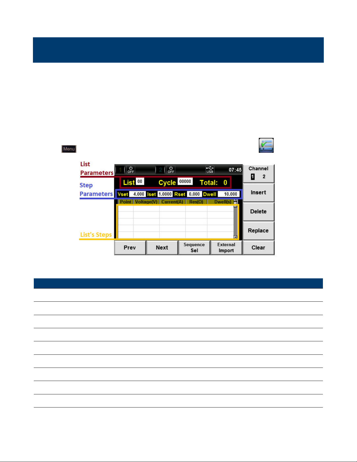
ListParametersViewandeditthelistparameters.
StepParametersViewandeditthestepparameters.
buttonthenusethenavigationkeysorthesoftkeystoselecttheicon.
Figure8.1ListInterface
SettingDescription
ChannelSelectachannel.
InsertInsertasteptotheselectedlist.
DeleteDeletetheselectedstep.
ReplaceReplacetheselectedstep.
SequenceSelEntertheSequenceSelectmenu.
ExternalImportImportalistfromaUSB.
ClearClearallstepsofselectedlist.
Table8.1ListInterface
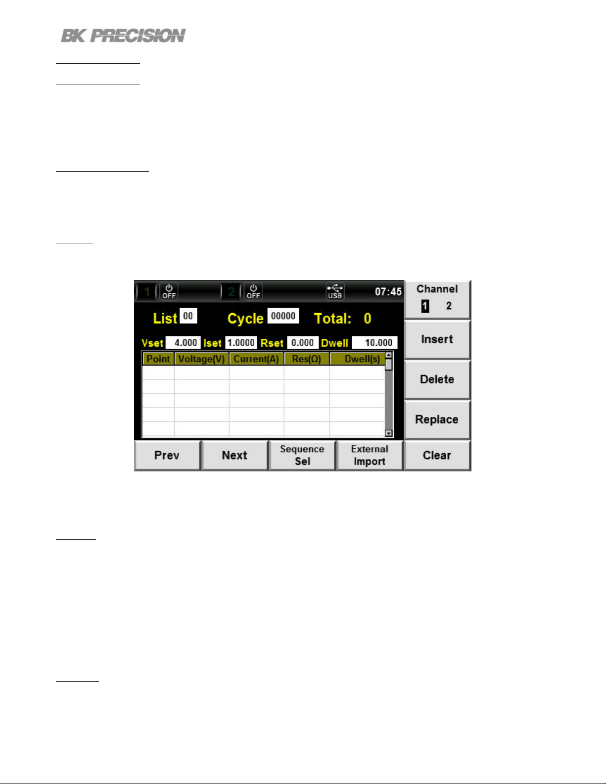
Page 65

List65
8.1ListSetup
UponenteringtheListInterfacethelastselectedlistwillbedisplayed.
Channel
Beforeeditinganyparametersensurethecorrectchannelisselected.Listmemoryisnotsharableacross
channels.Thereforeifalistisconguredinthewrongchanneltheotherchannelwillnotbeabletorun
saidlist.
PresstheF6softkeytotogglebetweenchannel1and2.
Channel1selectedChannel2selected
Figure8.2SelectChannel
8.1.1ListParameters
Afterselectingthedesiredchannelthelisttobeconguredmustbeselected.
•Selectthelisttobecongured.(0to19)
–Usethe
–Oncethelistparameterischosenusethenumerickeypadortherotaryknobtosetalist.
•Setthecycletimeofthelist.Thelistcanbecycledupto65535times.
–Usethe
–Oncethecycleparameterischosenusethenumerickeypadortherotaryknobtosetalist.
keystonavigatethelistandstepparameters.
keystonavigatethelistandstepparameters.
Note:
TheTotalparameterintheListParametersectioncannotbeedited.Itdisplaysthenumberof
stepsintheselectedlist. ToedittheselectedlistseesectionStepParameters.
Page 66
List66
8.2EditList
Alistcanbeeditedbyinserting,deleting,orreplacingaselectedstep.IfanewlistisdesiredtheClear
optioncanbeusedtodeleteallparametersatonce.
ListNavigation
UsetheF1andF2softkeystonavigatethesetsteps.
Clear
PresstheF5softkeytoclearallsetstepsoftheselectedlist.
Figure8.3ListClear
Insert
PresstheF7softkeytoinsertastep.Thestepwillbeinsertedinthefollowingpoint.Thereforeifthestep
selectedispoint2,thestepinsertedwillbeinpoint3.
IfthelisthasnostepandnopositionisselectedpressingtheF7softkeywillinsertastepinposition
0. Ifthelisthasnostepsposition0isselectedpressingtheF7softkeywilldisplayanOutofRange!
message.
Delete
PresstheF8softkeytodeletetheselectedstep.Deletingastepwillsetallthefollowingstepsone
positiondown.
Page 67

List67
Replace
PresstheF9softkeytoreplacetheselectedstepwithastepconsistingoftheparameterssetintheStep
Parameterssections.
Navigatetothesteptobereplacedbeforemakingchangestothestepparameters.
ChangesmadeintheStepParameterssectionswillnotbesavedwhennavigatingbetweenchannels.
8.2.1StepParameters
Thevoltage,current,resistance,anddwelltimeofastepcanbecongured. Allparametersofastep
mustbeconguredatonce.Therefore,onceastephasbeensetitcanbedeletedorreplacedbutnot
edited.
Figure8.4StepParameterSection
Tocongurethestepparameters:
1.Selecttheparametertobecongure.
–Usethe
–Oncethestepparameterischosenusethenumerickeypadortherotaryknobtosetalist.
keystonavigatethelistandstepparameters.
Page 68

List68
8.3SequenceSel
Thesavedlistcanruninaspeciedsequence.Thiscanbeusedtochainvariouslistortoexpandthe
cycletimeofapreviouslistthathasexceededthemaximumcycledtime.
ToentertheSequenceSelmenu:
Pressthe
ThenpresstheF3softkey.
PresstheF6softkeytotogglebetweenchannel1andchannel2.
buttonthenusethenavigationkeysorthesoftkeystoselecttheicon.
Figure8.5SequenceSel
The
TheselectedlistcanbeenabledordisabledinthesequencebypressingtheF7orF8softkey.
ListthatwillruninthesequencewillbemarkedwithaYintheSelectsection.
ListthatwillnotruninthesequencewillbemarkedwithaNintheSelectsection.
keysareusedtonavigatetheavailablelistoftheselectedchannel.
Example
Fromgure8.5channel1wouldonlyrunlist5beforeendingthelistmode.
Channel2wouldonlyrunlist1eventhoughlist0ismarkedY.List0wouldnotruninthesequence
becauseitscycletimeissetto0.Ifcycletimeforlist0wassetto1orgreaterthantriggeringlistrunon
channel2wouldcausetheoutputtorunthroughlist0followedbylist1.
Page 69

8.3.1RunningaList
Listsequencecanbeinitiatedintwoways:
ON/OFF
PressingtheF1softkeyintheSequenceSelmenuwillrunthesequenceofchannel1.
PressingtheF2softkeyintheSequenceSelmenuwillrunthesequenceofchannel2.
Trigger
Thelistsequencecanbeinitiatedusingthebutton.
Toenablethisfunction:
•PresstheF5softkeywhileintheSequenceSelmenutotogglebetween:
List69
–1enableTrigSelforchannel1.Pressing
channel1.
–2enableTrigSelforchannel2.Pressing
channel2.
–AllenableTrigSelforbothchannel1and2.Pressing
inbothchannel1and2.
–NoselectiondisableTrigSel.
willinitiatethelistsequenceprogrammedin
willinitiatethelistsequenceprogrammedin
willinitiatethelistsequenceprogrammed
Page 70

List70
8.3.2ExternalImport
ExternallyconguredlistcanbeloadedintotheinternalmemoryusingaUSBdrive.Conguratingalist
externallyfacilitatesthecongurationprocessaswellasallowstorageoflistoutsidethelimitedinternal
memoryofthedevice.
Tocreatealoadablele:
1.CreateanewexceldocumentwiththenameListCHx
2.Nametherst4cellsofrow1asshowningure
Figure8.6FileFormat
3.Settheparametersofeachstep,wheretheStepNumber=RowNumber-2.
8.6
4.Savetheleasa.csvle.
5.LoadtheletoaUSBdriveandconnectthatUSBdrivetotheUSBportlocatedinthefrontpanel.
6.NavigatetotheListInterface.
7.Selectthelistnumberwherethesavedlistwillbeimportedto.
8.PresstheF4softkeytoimportthelist. Thedevicewillautomaticallyidentifyandsavetheletothe
selectedlist.
Page 71

Math
TheMathInterfaceallowsforcongurationofthelterthatusedtoacquiremeasurements,aswellas
congurationofthebuerwhichstoresthemeasuredinformation.
ToentertheMathInterface:
Pressthe
keythenusethenavigationkeysorthesoftkeystoselecttheicon.
FilterMenuBuerMenu
Figure9.1MathInterface
SettingDescription
Filter
FilterChannelSelectthechanneltobecongure.
FilterStateEnable/disablelteringofmeasurements.
FilterTypeSettheltertypefordatabuer.
SampleRateSetthesamplerateforthedatabuer.
SampleCountSetthesamplecountforthedatabuer.
Buer
BuerSizeSetthebuersize.(1to1,024)
BuerStatisticsSetthestatistic.
BuerModeSetthebuermode.
AutoClearSettheautoclearstate.
ClearClearthebuer.
ExporttoUSBExportbuerdatatoUSBasBufCH1_xx.txtle.
Table9.1MathInterface
Page 72

Math72
9.1Filter
Thelterisinsertedinthevoltageandcurrentmeasurementcircuit.Thelterinuencesthemeasurement
ofvoltageandcurrent.
Theinuencethelterhasonthemeasurementsdependsonthetypeoflterthatisselected.Formore
informationreadthecorrespondingsectionoftheltertype.
ToentertheFilterMenu:
PresstheF1softkeywhileintheMathInterface.
9.1.1FilterChannel
Filtersettingsarenotsharedbetweenchannels.Beforeconguringanysettingsthechanneltobe
conguredmustbeselected.
PresstheF6softkeytotogglebetweenchannel1and2.
Thetextcoloroftheltersettingswillsettoindicatetheselectedchannel.
9.1.2FilterState
Fortheltersettingtobeappliedtheltermustbeenabled.
ToenableFilterState:
1.IntheMathInterfaceusethe
2.SelecttheFilterState.
–Whenselectedtheparameterwillbehighlightedinpurple.
3.PresstheF7softkeytoenablethelterorpresstheF8softkeytodisablethelter.
tonavigatetheavailablesettings.
Whenthelterisenabled,noiseandhigh-frequencycomponentsfromtheinverterordistortionwaveform
canbeltered.Thecutofrequencyofthelteris40Hz.
Page 73

9.1.3FilterType
Thelteralgorithmcanbesetto:Average,Hanning,orRectangle.
TosettheFilterType:
Math73
1.IntheMathInterfaceusethe
2.SelecttheFilterType.
–Whenselectedtheparameterwillbehighlightedinpurple.
3.Pressthecorrespondingsoftkeytoselectthedesiredltertype.
tonavigatetheavailablesettings.
Figure9.2FilterType
Average
Theaverageltertakesanaverageofthecollectedmeasurements.Thenumberofcollectedmeasurements
canbespeciedbyconguringtheSampleRateandtheSampleCount.
TosettheltertypeasRectangle:
PresstheF7softkeywhentheFilterTypesettingisselected.
Hanning
TheHanninglterisalowpasslterthatisveryeectiveinreducingnoise.Thelterreacheszero
quicklyallowingittolternoise,butalsocausingittolosetheedgesofthesignal.
Page 74

Math74
TosettheltertypeasHanning:
PresstheF8softkeywhentheFilterTypesettingisselected.
Rectangle
TheRectanglelterisalowpasslterthatisveryeectiveinreducingnoise. Thelterreducesnoise
withoutlosingtheedgesofthesignal.
TosettheltertypeasRectangle:
PresstheF9softkeywhentheFilterTypesettingisselected.
9.1.4SampleRate
Thesampleratedenesthenumberofsamplespersecondtaken.Thesampleratecanbecongured
from1to30000.
Tocongurethesamplerate:
•EntertheMathInterfaceandusethe
•SelecttheSampleRatesetting.
–Whenselectedtheparametertheleastsignicantdigitwillbehighlightedinablinkingblackbox.
•Pressthecorrespondingsoftkeytoselectthedesiredltertype.
tonavigatetheavailablesettings.
9.1.5SampleCount
Thesamplecountdenesthetotalnumberofsamplestaken.Thesamplecountcanbeconguredfrom
50to600.
Tocongurethesamplerate:
•EntertheMathInterfaceandusethe
tonavigatetheavailablesettings.
•SelecttheSampleCountsetting.
–Whenselectedtheparametertheleastsignicantdigitwillbehighlightedinablinkingblackbox.
•Usethenumerickeypadortherotaryknobalongwiththe
tosetthevalue.
Page 75

Math75
9.2Buer
Thebuerstoresthemeasurementresultsanddatauntilthemaxcapacityisreached. Thecollected
datacanconsistofvoltagesandcurrents.
Whencollectingdatarapidlyitispreferredtostorethedatainthebuerandexportingthedataoncethe
sampleshavebeencollected.Thisalleviatestiminglimitationthatmaybeoccurwhenrapidlyacquiring
datathrougharemoteinterface.
ToentertheBuerMenu:
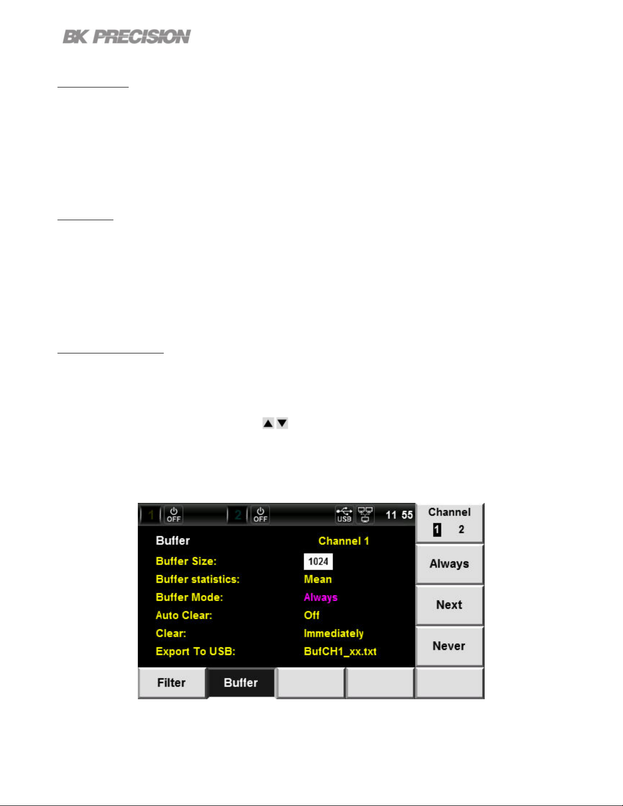
PresstheF2softkeywhileintheMathInterface.
Figure9.3BuerMenu
9.2.1BuerChannel
Buersettingsarenotsharedbetweenchannels.Beforeconguringanysettingsthechanneltobe
conguredmustbeselected.
PresstheF6softkeytotogglebetweenchannel1and2.
Thetextcoloroftheltersettingswillsettoindicatetheselectedchannel.
9.2.2BuerSize
Theamountofmeasurementsthatcanbestoredineachchannel’sbuerislimitedto1024.
Tosetthebuersize:
Page 76

Math76
•EntertheMathInterfaceandusethe
•SelecttheBuerSizesetting.
–Whenselectedtheparametertheleastsignicantdigitwillbehighlightedinablinkingblackbox.
•Usethenumerickeypadortherotaryknobalongwiththe
tonavigatetheavailablesettings.
tosetthevalue.
9.2.3BuerStatistics
Thedatacollectedcanbeconguredtosaveaspeciedstatistic.Thesamplesizecollectedisraw
informationfromwhichtheunitcalculatesameasurement.
Tosetthestatistictypethemeasurementissavedas:
•EntertheMathInterfaceandusethe
•SelecttheBuerStatisticssetting.
–Whenselectedtheparameterwillbehighlightedinpurpleandtheavailablestatisticsaredisplayed.
tonavigatetheavailablesettings.
Figure9.4BuerStatistics
•Pressthecorrespondingsoftkeytoselectthedesiredstatistictype.
Page 77
Mean/Peak
PressingtheF7softkeytotogglebetweenMeanandPeak.
•Mean:Themeasurementsavedwillbetheaverageofallthesamplestaken.
•Peak:Themeasurementwillbesavedasapeakvalue.
Max/Min
PressingtheF8softkeytotogglebetweenMaxandMin.
•Max:Themeasurementsavedwillbethemaximumsamplerecorded.
•Peak:Themeasurementsavedwillbetheminimumsamplerecorded.
Math77
9.2.4BuerMode
Setthesavecontrolmodeoftheselectedbuer.InordertostoremeasurementsTracemustbeenabled.
Tosetthebuermode:
•EntertheMathInterfaceandusethe
•SelecttheBuerModesetting.
–Whenselectedtheparameterwillbehighlightedinpurpleandtheavailablemodesaredisplayed.
tonavigatetheavailablesettings.
Figure9.5BuerMode
•Pressthecorrespondingsoftkeytoselectthedesiredbuermode.
Page 78

Math78
Always
PresstheF7softkeytosetthebuermodeasAlways.
ThebuerqueuewillbesettoFIFO(rstinrstout). Themeasurementswillbestoredandreadas
theyoccur.Whenthebuerisfulltheoldestmeasurementwillbedeletedinordertoincludethenewest
measurement.
Next
PresstheF8softkeytosetthebuermodeasNext.
Writeprotectionwillbeenabled. Oncethebuerisfullnewmeasurementswillnotbewrittenintothe
buer.
Never
PresstheF9softkeytosetthebuermodeasNever.
Writeprotectionwillbedisabled.Nomeasurementswillbestoredinthebuer.
9.2.5AutoClear
Settheautomaticclearstateoftheselectedbuer.
TosetthestateofAutoClear:
•EntertheMathInterfaceandusethe
•SelecttheAutoClearsetting.
–WhenselectedtheparameterwillbehighlightedinpurpleandtheOnOsettingswillbedisplayed.
–PresstheF7softkeytoenableautoclear.
–PresstheF8softkeytodisableautoclear.
tonavigatetheavailablesettings.
Note:
AutoClearwillnotclearthebuerwhenBuerModeissettonextornever.
Page 79

9.2.6Clear
Immediatelyclearallmeasurementssavedinthebuer.
Toclearthebuer:
Math79
•EntertheMathInterfaceandusethe
•SelecttheClearsetting.
–Whenselectedtheparameter"Immediately"willbehighlightedinpurpleandtheYesoptionwill
bedisplayed.
•PresstheF6softkeytoclearthebuer.
–ThemessageClearSuccessful!willbedisplaytosignifythebuerhasbeencleared.
tonavigatetheavailablesettings.
Note:
ClearImmediatelywillclearthebuerregardlessofBuerModechosen.
9.2.7ExporttoUSB
ThemeasurementsstoredinthebuercanbeexportedtoaUSB.
Themeasurementswillbestoredina.txtlenamed"BufCH1_xx.txt"or"BufCH2_xx.txt"depending
onthechannel.
Toexportthebuer’sdata:
•EntertheMathInterfaceandusethe
•SelecttheExporttoUSBsetting.
–WhenselectedtheparameterwillbehighlightedinpurpleandtheSaveoptionwillbedisplayed.
•PresstheF6softkeytoexportthedata.
–ThemessageSaveSuccessful!willbedisplaytosignifythedatahasbeenexported.
tonavigatetheavailablesettings.
Page 80

System
TheSystemInterfaceprovidesinformationaboutthedeviceandallowsmodicationsofcertainsettings.
ToentertheSystemInterface:Pressthe
Figure10.1SystemInterface
SettingsDescription
OpenLogalloperations.
buttonandselecttheicon.
SysLog
CloseStopoperationlogging.
SysConf
DateSetthedate.
TimeSetthetime.
BrightnessSetthedisplaybrightness.
BeepEnable/Disablethekeybeep.
SystemResetSetthedevicesettingstodefault.
SystemSelfTestPerformasystemself-test.
SystemProtectionClearClearallsystemprotectionstriggered.
SysInfo
SysComm
ModeSelectthecommunicationinterface.
SysCal
Table10.1SystemInterface
Page 81

10.1SysLog
Theinstrumentiscapableofrecordingalloperationsina.txtle.
ToenableSysLog:
•EntertheSystemInterface.
•PresstheF1softkeytoentertheSysLogmenu.
•InsertaUSBdriveintheUSBportlocatedinthefrontpanel.
–JournalLogcannotbesavedtotheinternalmemory.
–PleaseinsertUSBDevice!willbedisplayeduntilaUSBisinserted.
•PresstheF6softkeytobeginlogging.
System81
–SystemJournalOpenwillbedisplayedtheoperationrecordingisinprogress.
Figure10.2SystemLogOpen
Page 82
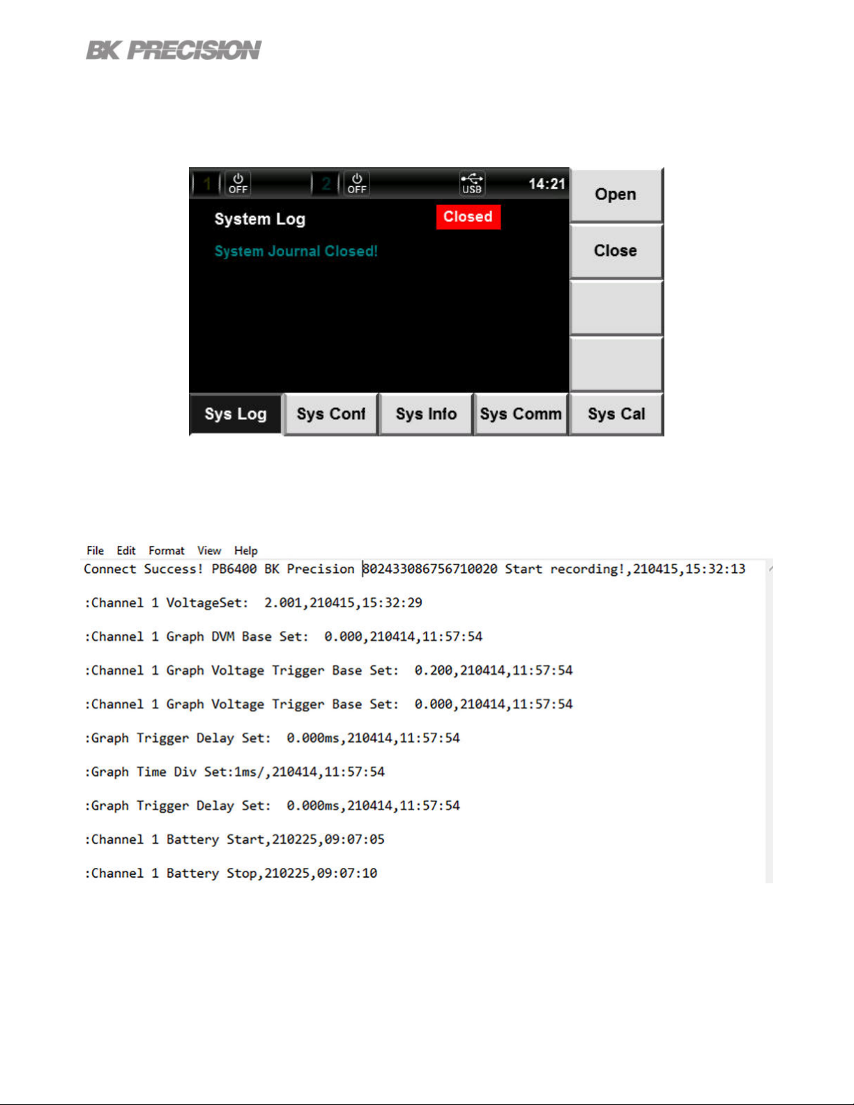
•PresstheF7softkeytostopoperationrecording.
–SystemJornualClosedwillbedisplayedwhenoperationrecordingisdisabled.
Figure10.3SystemLogClosed
System82
Operationsincludealloutputandmeasurementsfunctions.
Figure10.4JournalFormat
Page 83
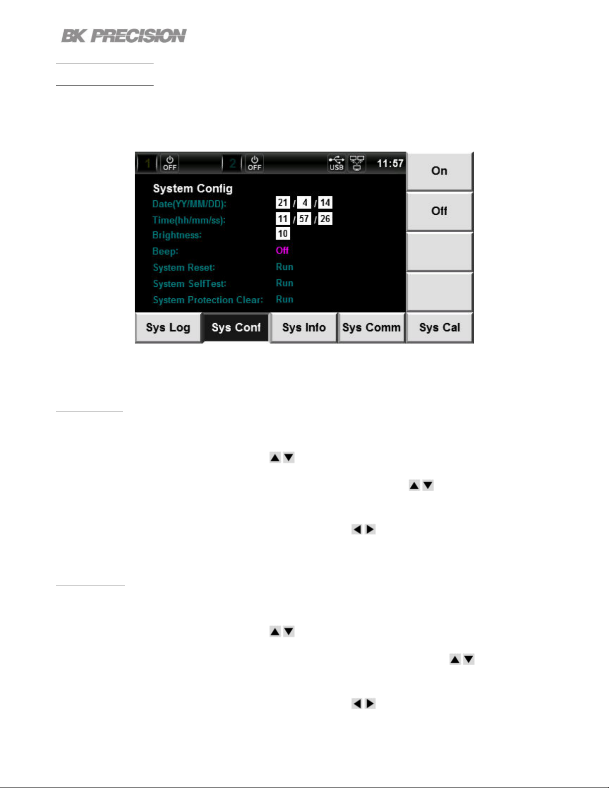
10.2SysConf
ToentertheSysConfmenu:
•EntertheSystemInterfacethenpresstheF2softkey.
System83
Figure10.5SysConf
10.2.1Date
TosettheDate:
•EntertheSystemInterfaceandusethe
–Theyear,month,anddayarepartoftheavailablesettings.Usethe
eachparameterofthedate.
•Usethenumerickeypadortherotaryknobalongwiththe
tonavigatetheavailablesettings.
10.2.2Time
TosettheTime:
•EntertheSystemInterfaceandusethe
tonavigatetheavailablesettings.
navigationkeystoselect
tocongureeachparameter.
–Thehour,minutes,andsecondsarepartoftheavailablesettings.Usethe
toselecteachparameter.
•Usethenumerickeypadortherotaryknobalongwiththe
tocongureeachparameter.
navigationkeys
Page 84

10.2.3Brightness
TosettheBrightnessofthedisplay:
System84
•EntertheSystemInterfaceandusethe
•NavigatetotheBrightnesssetting.
•Thebrightnesscanbesetfrom1to10.{1=dimmest|10=brightest}
–Usethenumerickeypadtoenterabrightnesslevel.
–Therotaryknobalongwiththe
•Pressthe
buttontosetthebrightnesslevel.
canbeusedtoeditthebrightnesslevel.
tonavigatetheavailablesettings.
10.2.4Beep
TosettheBeepstate:
•EntertheSystemInterfaceandusethe
•NavigatetotheBeepsetting.
tonavigatetheavailablesettings.
–PresstheF6softkeytoenableBeep.
–PresstheF7softkeytodisableBeep.
WhenBeepisenabled,theunitwilloutputabeepafterpressinganybutton,softkey,ornavigationkey.
Page 85

10.2.5SystemReset
Tofactoryresetalltheinstrumentssettings:
System85
•EntertheSystemInterfaceandusethe
•NavigatetotheSystemResetsetting.
•PresstheF6softkeytobeginthefactoryreset.
•Thedevicewillaskforvericationbeforestartingthefactoryreset.
tonavigatetheavailablesettings.
Figure10.6ResetVerication
•PresstheF6softkeyagaintobeginthefactoryreset.
–TocancelthefactorysettingspresstheF7button.
Page 86

10.2.6SystemSelf-Test
Thesystemself-testveriesiftherisanissueswiththeinstrument.
Tobeginaself-test:
System86
•EntertheSystemInterfaceandusethe
•PresstheF2SofkeytoselectSysConf.
•NavigatetotheSystemSelf-Testsettings,thenpresstheF6softkeytobegintheself-test.
•Thedevicewillaskforvericationbeforestartingtheself-test.
tonavigatetheavailablesettings.
Figure10.7Self-Test
•PresstheF6softkeyagaintobegintheself-test.
–TocancelthefactorysettingspresstheF7button.
Duringtheself-testthedisplaycyclethroughvarioussolidcolor.
OncethetestiscompletedtheSystemSelf-TestDone!messagewillappear
Figure10.8.
Page 87

Figure10.8Self-TestDone
10.2.7SystemProtectionClear
SystemProtectionClearclearsalltriggeredprotectionandoutputlatchstatus.
Toclearthetriggeredprotections.
System87
•EntertheSystemInterfaceandusethe
•NavigatetotheSystemSelf-Testsetting.
•PresstheF6softkeytoclearalltriggeredprotections.
•Thedevicewillaskforvericationclearingtheprotectionstates.
tonavigatetheavailablesettings.
Figure10.9ProtectionClear
•PresstheF6softkeyagaintobegintheself-test.
–TocancelthefactorysettingspresstheF7button.
Page 88

10.3SysInfo
Toviewtheinstrument’sinformation:
•EntertheSystemInterface.
•PresstheF3softkeytoentertheSystemInformationmenu.
System88
Figure10.10SysInfo
Page 89

10.4SysComm
Thefollowinginterfacescanbesettoremotelycontroltheinstrument.
System89
ToentertheSysCommmenu:
•EntertheSystemInterface.
•PresstheF4softkey.
USBTMC
LAN
Figure10.11SystemCommunication
Page 90

10.4.1USBTMC
USBTMCissetasthedefaultinterface.
TosettheremoteinterfacetoUSBTMC:
•EntertheSystemInterface.
•PresstheF4softkeytoentertheSystemCommunicationmenu.
System90
•PresstheF6softkeytoselecttheUSB
Figure10.12USBTMC
𝑇𝑀𝐶
interface.
Figure10.13VISAResourceString
TheVISAResourcestringgivesUSB0::<VendorID>::<ProductID>::<SerialNumber>:INST
ExampleFromgure10.13
<VendorID>=0x3121
<ProductID>=0x0001forBCS6400
<SerialNumber>=802433086756710020
Page 91

10.4.2LAN
TosettheLANSettings
•EntertheSystemInterface.
•PresstheF4softkeytoentertheSystemCommunicationmenu.
•PresstheF8softkeytoselecttheLANinterface.
ThefollowingsettingsareavailableinLANSettings:
•
IPMode
•IPAddress
•Subnet
Mask
System91
•GatewayIP
Figure10.14LANSettings
IPMode
•EntertheLANmenuandusethetonavigatetheavailablesettings.
•NavigatetotheIPModesetting.
–PresstheF6softkeytoselectManualtosethowtheLANsettingswillbecongured.
–PresstheF7softkeytoselectDynamicHostCongurationProtocol(DHCP)
DHCP
TheeasiestwaytoconguretheLANsettingsistosettheIPModetoDHCP.DHCPwillautomatically
assignallLANsettings.TheLANsettingswillnotbecongurablewhenDHCPisselected.
Page 92

System92
Manual
Congurethefollowingparametersmanually.
IPAddress
TheIPAddressisaunique32bitstringofnumbersseparatedin4partsbyperiods.Eachofthe4parts
contains8bitsandarereferredtoasoctets.
ToenteranIPaddress:
•EntertheSystemInterfaceandusethe
•NavigatetotheIPAddresssetting.
•UsethenumerickeypadtoentertheselectedportionoftheIPaddress.
•Usethe
keystonavigateeachoctet.
tonavigatetheavailablesettings.
SubnetMask
SubnetMaskhelpsdistinguishwhichpartoftheiPaddressisthenetworkaddressandthehostaddress.
TosetSubnetMask:
•EntertheSystemInterfaceandusethe
•NavigatetotheSubnetMasksetting.
•UsethenumerickeypadtoentertheselectedportionoftheIPaddress.
tonavigatetheavailablesettings.
•Usethekeystonavigateeachoctet.
GatewayIP
ThegatewayaddressisbydefaulttheIPaddressofthenetworkdevicethatconnectstheinstrument.
IfIPModeissettoDHCPGatewayIPdoesnothavetobeset.
TosetGatewayIP:
•EntertheSystemInterfaceandusethe
•NavigatetotheGatewayIPsetting.
tonavigatetheavailablesettings.
Page 93

•UsethenumerickeypadtoentertheselectedportionoftheIPaddress.
System93
•Usethe
keystonavigateeachoctet.
10.5SysCal
ToentertheSysCalmenu:
•EntertheSystemInterface.
•PresstheF5softkey.
•Enterthe4digitpassword.
Figure10.15SystemCal
Page 94

Battery Charger/Simulator and DC Power Supply
BCS Series
Specifications
Model BCS6401 BCS6402
Channels 2 1
Voltage
CH1 CH2
± 30 VHigh ± 15 V 0 to 15 V
Low ± 9 V 0 to 9 V
Max Source / Sink Current
High 3 A
5 A
Low 5 A
Power 45 W per channel, up to 90 W combined 150 W
Variable Output Impedance 0 to 1 Ω
Load Regulation ± (% output + offset)
Voltage ≤ 0.01% + 2 mV
Current ≤ 0.05% + 1 mA
Line Regulation ± (% output + offset)
Voltage ≤ 0.02% + 2 mV
Current ≤ 0.05% + 1 mA
Ripple and Noise (20 Hz to 20 MHz)
Normal Mode Voltage p-p ≤ 3 mV ≤ 4 mV
Normal Mode Voltage rms ≤ 1 mV
Normal Mode Current rms ≤ 1 mA
Programming Resolution
Voltage 1 mV
Current 0.1 mA
Variable Output Impedance 1 mΩ
Readback Resolution
Voltage 1 mV
Current
5 A Range 0.1 mA
5 mA Range 100 nA
Programming Accuracy ± (% output + offset)
Voltage ≤ 0.02% + 3 mV
Current ≤ 0.05% + 2 mA ≤ 0.05% + 3 mA
Variable Output Impedance ≤ 0.1% + 3 mΩ
Readback Accuracy ± (% output + offset)
Voltage ≤ 0.02% + 2 mV ≤ 0.02% + 3 mV
Current
5 A Range ≤ 0.05% + 0.2 mA ≤ 0.05% + 3 mA
5 mA Range
(1)
≤ 0.05% + 2 µA
Temperature Coefficient ± (% output + offset) / °C
Voltage 0.005% + 0.2 mV 0.005% + 0.4 mV
Current 0.005% + 0.2 mA 0.01% + 0.2 mA
Resistance 0.02% + 0.5 mΩ
Note: All specifications apply to the unit after a temperature stabilization time of 15 minutes over an ambient temperature range of 23 °C ± 5 °C.
Specifications are valid for single unit operation only.
Page 95

Battery Charger/Simulator and DC Power Supply
BCS Series
Specifications (cont.)
Model BCS6401 BCS6402
Output Response Time
(2)
Rise Time
Voltage
Full load ≤ 500 µs ≤ 150 µs
No load ≤ 500 µs ≤ 150 µs
Current Full load
Fast mode ≤ 150 µs Fast mode ≤ 150 µs
Normal mode ≤ 10 ms Normal mode ≤ 10 ms
Fall Time Voltage
Full Load
(3)
≤ 150 µs ≤ 50 µs
No load ≤ 1 ms ≤ 150 µs
(4)
Transient Response
(5)
Time ≤ 50 µs ≤ 30 µs
DVM
Measurement Range -20 V to +20 V -30 V to +30 V
Resolution 1 mV
Accuracy 0.02% + 3 mV
General
Remote Sense Compensation 1 V
Command Response Time
(6)
5 ms
Power Factor 0.7 max.
I/O Interfaces USB (USBTMC-compliant) and LAN
AC Line Input 110/220 VAC ± 10%, 47 Hz to 63 Hz
Isolation (output to ground) 100 VDC max.
Output Impedance
(output off, typical)
Output-off state
Normal
150 kΩ 200 kΩ
Output-off state
Relay off
≥ 1 GΩ
(7)
≥ 1 GΩ
Protection Functions
OVP/OCP/OTP/Reverse voltage
protection
OVP/OCP/OTP
Maximum Rated Input Power 500 VA
Temperature
Ratings
Operation 32 °F to 104 °F (0 °C to 40 °C)
Storage 14 °F to 158 °F (-10 °C to 70 °C)
Dimensions (W x H x D) 8.9” x 3.5” x 18.75” (226 x 88.2 x 476.26 mm)
Weight 19.85 lbs (9 kg) 17.64 lbs (8 kg)
Warranty 3 Years
Standard Accessories Power cord & certificate of calibration
Optional Accessories Rack mount kit (RK2US)
(1) The current readback accuracy of the 5 mA range is measured in constant voltage mode.
(2) From 10% to 90% or from 90% to 10% of total power excursion. Using positive output polarity.
(3) Fall time at full load when output is disabled.
(4) The set voltage will change to 0 V when the power supply output is 30 V.
(5) Time for output voltage to recover within 50 mV for a load change 50-100% of full load. Output speed set to Fast.
(6) Typical time required for output to begin to change following receipt of command data.
(7) Relay off function only supported for CH1.
Regulatory Compliance
Safety Low Voltage Directive (LVD) 2014/35/EU, EN61010-1:2010
Electromagnetic Compatibility EMC Directive 2014/30/EU, EN61326-1:2013
Page 96

ServiceInformation
WarrantyService:Pleasegotothesupportandservicesectiononourwebsiteatbkprecision.comto
obtainanRMA#. Returntheproductintheoriginalpackagingwithproofofpurchasetotheaddress
below.ClearlystateontheRMAtheperformanceproblemandreturnanyleads,probes,connectorsand
accessoriesthatyouareusingwiththedevice.
Non-WarrantyService:Pleasegotothesupportandservicesectiononourwebsiteatbkprecision.com
toobtainanRMA#.Returntheproductintheoriginalpackagingtotheaddressbelow.Clearlystateon
theRMAtheperformanceproblemandreturnanyleads,probes,connectorsandaccessoriesthatyou
areusingwiththedevice. Customersnotonanopenaccountmustincludepaymentintheformofa
moneyorderorcreditcard.Forthemostcurrentrepairchargespleaserefertotheserviceandsupport
sectiononourwebsite.
ReturnallmerchandisetoB&KPrecisionCorp.withprepaidshipping.Theat-raterepairchargefor
Non-WarrantyServicedoesnotincludereturnshipping.ReturnshippingtolocationsinNorthAmericais
includedforWarrantyService. Forovernightshipmentsandnon-NorthAmericanshippingfeesplease
contactB&KPrecisionCorp.
Includewiththereturnedinstrumentyourcompletereturnshippingaddress,contactname,phonenumber
anddescriptionofproblem.
B&KPrecisionCorp.
22820SaviRanchParkway
YorbaLinda,CA92887
bkprecision.com
714-921-9095
Page 97

LIMITEDTHREE-YEARWARRANTY
B&KPrecisionCorp.warrantstotheoriginalpurchaserthatitsproductsandthecomponentpartsthereof,
willbefreefromdefectsinworkmanshipandmaterialsforaperiodofthreeyearsfromdateofpurchase.
B&KPrecisionCorp.will,withoutcharge,repairorreplace,atitsoption,defectiveproductorcomponent
parts.Returnedproductmustbeaccompaniedbyproofofthepurchasedateintheformofasales
receipt.
Tohelpusbetterserveyou,pleasecompletethewarrantyregistrationforyournewinstrumentviaour
websitewww.bkprecision.com
Exclusions:Thiswarrantydoesnotapplyintheeventofmisuseorabuseoftheproductorasa
resultofunauthorizedalterationsorrepairs.Thewarrantyisvoidiftheserialnumberisaltered,
defacedorremoved.
B&KPrecisionCorp.shallnotbeliableforanyconsequentialdamages,includingwithoutlimitation
damagesresultingfromlossofuse.Somestatesdonotallowlimitationsofincidentalorconsequential
damages.Sotheabovelimitationorexclusionmaynotapplytoyou.
Thiswarrantygivesyouspecicrightsandyoumayhaveotherrights,whichvaryfromstate-to-state.
B&KPrecisionCorp.
22820SaviRanchParkway
YorbaLinda,CA92887
www.bkprecision.com
714-921-9095
Version:September12,2022
 Loading...