

Page 1

Page 2

2
Safety Summary
The following safety precautions apply to both operating and maintenance personnel and must be followed during all
phases of operation, service, and repair of this instrument.
Before applying power to this instrument:
• Read and understand the safety and operational information in this manual.
• Apply all the listed safety precautions.
• Verify that the voltage selector at the line power cord input is set to the correct line voltage. Operating the instrument
at an incorrect line voltage will void the warranty.
• Make all connections to the instrument before applying power.
• Do not operate the instrument in ways not specied by this manual or by B&K Precision.
Failure to comply with these precautions or with warnings elsewhere in this manual violates the safety standards of design,
manufacture, and intended use of the instrument. B&K Precision assumes no liability for a customer’s failure to comply
with these requirements.
Category rating
The IEC 61010 standard denes safety category ratings that specify the amount of electrical energy available and the
voltage impulses that may occur on electrical conductors associated with these category ratings. The category rating is
a Roman numeral of I, II, III, or IV. This rating is also accompanied by a maximum voltage of the circuit to be tested,
which denes the voltage impulses expected and required insulation clearances. These categories are:
Category I (CAT I): Measurement instruments whose measurement inputs are not intended to be connected to the
mains supply. The voltages in the environment are typically derived from a limited-energy transformer or a battery.
Category II (CAT II): Measurement instruments whose measurement inputs are meant to be connected to the mains
supply at a standard wall outlet or similar sources. Example measurement environments are portable
tools and household appliances.
Category III (CAT III): Measurement instruments whose measurement inputs are meant to be connected to the mains
installation of a building. Examples are measurements inside a building’s circuit breaker panel
or the wiring of permanently-installed motors.
Category IV (CAT IV): Measurement instruments whose measurement inputs are meant to be connected to the primary
power entering a building or other outdoor wiring.
Do not use this instrument in an electrical environment with a higher category rating than what is specied in this manual
for this instrument.
Page 3
3
You must ensure that each accessory you use with this instrument has a category rating equal to or higher than the
instrument’s category rating to maintain the instrument’s category rating. Failure to do so will lower the category rating
of the measuring system.
Electrical Power
This instrument is intended to be powered from a CATEGORY II mains power environment. The mains power should be
115 V RMS or 230 V RMS. Use only the power cord supplied with the instrument and ensure it is appropriate for your
country of use.
Ground the Instrument
To minimize shock hazard, the instrument chassis and cabinet must be connected to an electrical safety ground. This
instrument is grounded through the ground conductor of the supplied, three-conductor AC line power cable. The power
cable must be plugged into an approved three-conductor electrical outlet. The power jack and mating plug of the power
cable meet IEC safety standards.
Do not alter or defeat the ground connection. Without the safety ground connection, all accessible conductive parts
(including control knobs) may provide an electric shock. Failure to use a properly-grounded approved outlet and the
recommended three-conductor AC line power cable may result in injury or death.
Unless otherwise stated, a ground connection on the instrument’s front or rear panel is for a reference of potential only
and is not to be used as a safety ground. Do not operate in an explosive or ammable atmosphere.
Do not operate the instrument in the presence of ammable gases or vapors, fumes, or nely-divided particulates.
The instrument is designed to be used in oce-type indoor environments. Do not operate the instrument
• In the presence of noxious, corrosive, or ammable fumes, gases, vapors, chemicals, or nely-divided particulates.
• In relative humidity conditions outside the instrument’s specications.
• In environments where there is a danger of any liquid being spilled on the instrument or where any liquid can condense
on the instrument.
• In air temperatures exceeding the specied operating temperatures.
• In atmospheric pressures outside the specied altitude limits or where the surrounding gas is not air.
Page 4
4
• In environments with restricted cooling air ow, even if the air temperatures are within specications.
• In direct sunlight.
This instrument is intended to be used in an indoor pollution degree 2 environment. The operating temperature range is
0∘C to 40∘C and 20% to 80% relative humidity, with no condensation allowed. Measurements made by this instrument
may be outside specications if the instrument is used in non-oce-type environments. Such environments may include
rapid temperature or humidity changes, sunlight, vibration and/or mechanical shocks, acoustic noise, electrical noise,
strong electric elds, or strong magnetic elds.
Do not operate instrument if damaged
If the instrument is damaged, appears to be damaged, or if any liquid, chemical, or other material gets on or inside the
instrument, remove the instrument’s power cord, remove the instrument from service, label it as not to be operated,
and return the instrument to B&K Precision for repair. Notify B&K Precision of the nature of any contamination of the
instrument.
Clean the instrument only as instructed
Do not clean the instrument, its switches, or its terminals with contact cleaners, abrasives, lubricants, solvents, acids/bases,
or other such chemicals. Clean the instrument only with a clean dry lint-free cloth or as instructed in this manual. Not
for critical applications
This instrument is not authorized for use in contact with the human body or for use as a component in a life-support
device or system.
Do not touch live circuits
Instrument covers must not be removed by operating personnel. Component replacement and internal adjustments must
be made by qualied service-trained maintenance personnel who are aware of the hazards involved when the instrument’s
covers and shields are removed. Under certain conditions, even with the power cord removed, dangerous voltages may
exist when the covers are removed. To avoid injuries, always disconnect the power cord from the instrument, disconnect
all other connections (for example, test leads, computer interface cables, etc.), discharge all circuits, and verify there
are no hazardous voltages present on any conductors by measurements with a properly-operating voltage-sensing device
before touching any internal parts. Verify the voltage-sensing device is working properly before and after making the
measurements by testing with known-operating voltage sources and test for both DC and AC voltages. Do not attempt
any service or adjustment unless another person capable of rendering rst aid and resuscitation is present.
Do not insert any object into an instrument’s ventilation openings or other openings.
Page 5

5
Hazardous voltages may be present in unexpected locations in circuitry being tested when a fault condition in the circuit
exists.
Fuse replacement must be done by qualied service-trained maintenance personnel who are aware of the instrument’s fuse
requirements and safe replacement procedures. Disconnect the instrument from the power line before replacing fuses.
Replace fuses only with new fuses of the fuse types, voltage ratings, and current ratings specied in this manual or on
the back of the instrument. Failure to do so may damage the instrument, lead to a safety hazard, or cause a re. Failure
to use the specied fuses will void the warranty.
Servicing
Do not substitute parts that are not approved by B&K Precision or modify this instrument. Return the instrument to
B&K Precision for service and repair to ensure that safety and performance features are maintained.
For continued safe use of the instrument
• Do not place heavy objects on the instrument.
• Do not obstruct cooling air ow to the instrument.
• Do not place a hot soldering iron on the instrument.
• Do not pull the instrument with the power cord, connected probe, or connected test lead.
• Do not move the instrument when a probe is connected to a circuit being tested.
Compliance Statements
Disposal of Old Electrical & Electronic Equipment (Applicable in the European Union and other European
countries with separate collection systems)
This product is subject to Directive 2002/96/EC of the European Parliament
and the Council of the European Union on waste electrical and electronic equipment
(WEEE), and in jurisdictions adopting that Directive, is marked as being put on the
market after August 13, 2005, and should not be disposed of as unsorted municipal
waste. Please utilize your local WEEE collection facilities in the disposition of this
product and otherwise observe all applicable requirements.
Safety Symbols
Page 6
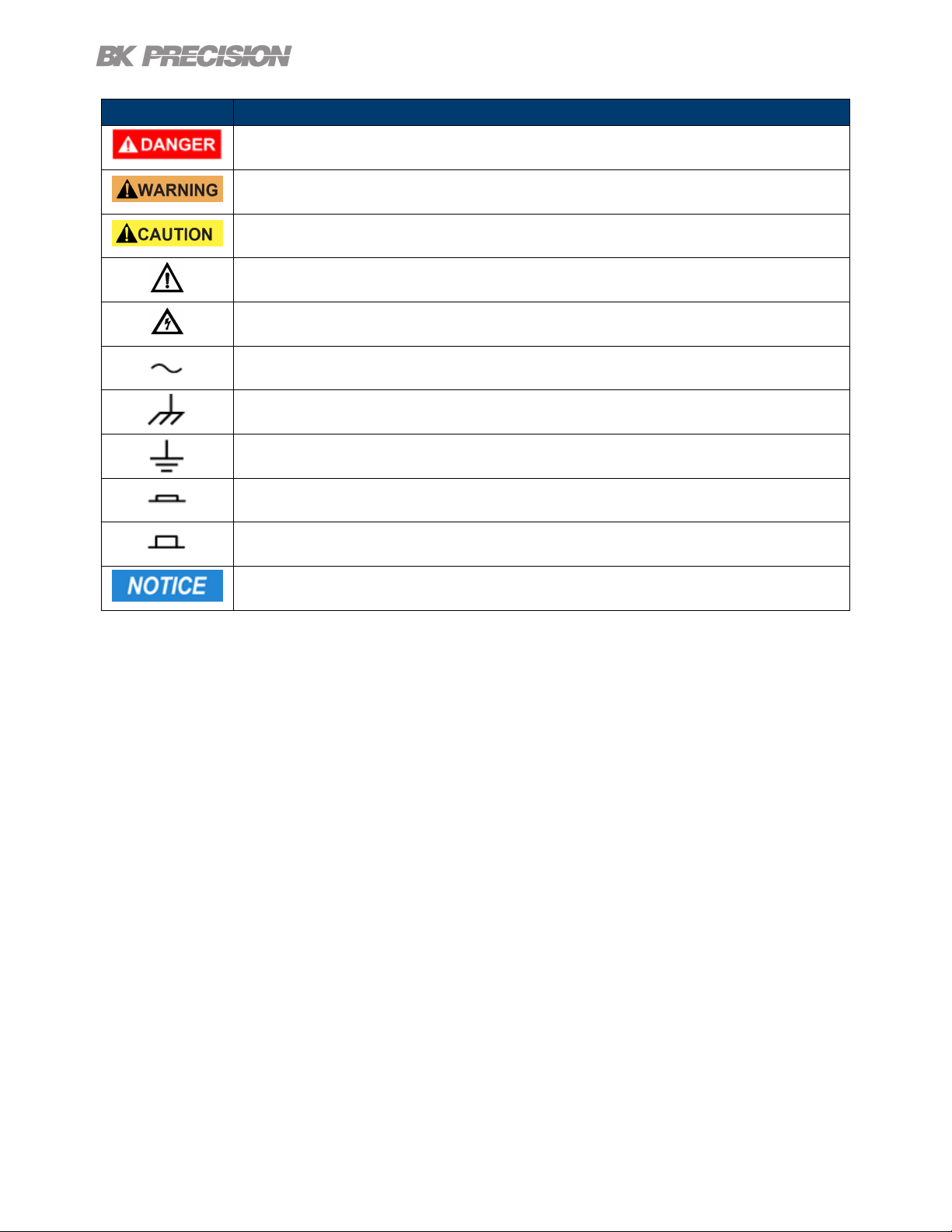
Symbol Description
Indicates a hazardous situation which, if not avoided, will result in death or serious injury.
Indicates a hazardous situation which, if not avoided, could result in death or serious injury
Indicates a hazardous situation which, if not avoided, will result in minor or moderate injury
Refer to the text near the symbol.
Electric Shock hazard
Alternating current (AC)
Chassis ground
Earth ground
Indicates the In position of the power switch when instrument is ON.
6
Indicates the Out position of the power switch when instrument is OFF.
Indicates practices not related to physical injury.
Table 1 Safety Symbols
Page 7

Contents
1 General Information 9
1.1 Features 9
1.2 Contents 10
1.3 Dimensions 10
1.4 Front Panel Overview 11
1.5 Display 12
1.6 Rear Panel Overview 13
2 Getting Started 14
2.1 Input Power and Fuse Requirements 14
2.2 Fuse Requirements 15
2.3 Fuse Replacement 15
2.4 Theory of Operation 16
2.5 Connections 16
2.6 Input 16
2.7 Sense 16
3 Measurement Modes 17
4 Measurement Setup 18
4.1 Setting DC Current Level 18
4.2 Setting AC Current Level 18
4.3 Setting Frequency and Sweep 19
4.3.1 Single Frequency 19
4.3.2 Sweep Mode 19
4.4 Making a Measurement 20
5 Verication Test 21
5.1 Verication Procedure 22
5.2 Verication Procedure to the Front Panel 23
5.2.1 Verication Setup 23
5.3 Compensating to the Test Leads 24
5.3.1 Setup 24
5.4 User Calibration 25
5.4.1 User Calibration to the Test Leads 25
5.4.2 User Calibration to the Pront Panel 26
6 Operating Software 28
6.1 Software Installation 28
6.2 Interface Conguration 28
6.3 Control Panel 29
6.3.1 Frequency/Amplitude 29
6.3.2 Sweep 30
6.3.3 Analysis 31
6.3.4 Sample 33
6.3.5 Output Condition 33
6.4 Running the Test 33
6.5 Test Results 34
6.6 Data Logging 35
Page 8

8
7 System Setup 36
7.1 Menu 36
7.1.1 Input Settings 36
7.1.2 Display Settings 36
7.1.3 I/O Conguration 37
7.1.4 Protection 37
7.1.5 System Setup 37
8 Remote Interface 38
8.1 USBVCP 38
8.2 RS-232 38
8.3 Ethernet 38
8.4 Local and Remote Mode 38
9 Service Information 39
10 LIMITED THREE-YEAR WARRANTY 40
Page 9
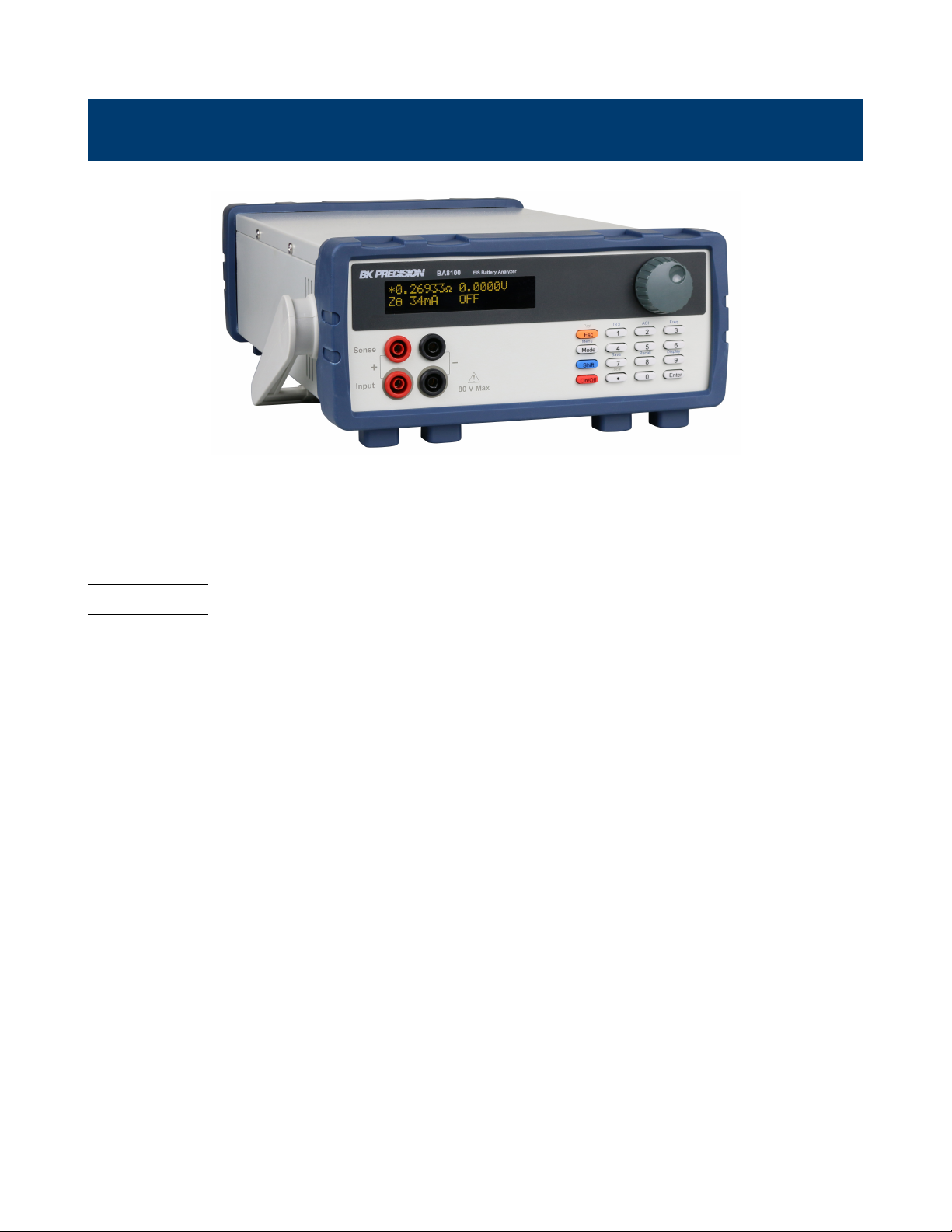
General Information
The BA8100 provides insight on a battery’s electrochemical and electrical properties. Using a sweep method called
Electrochemical Impedance Spectroscopy (EIS) the unit plots the battery’s response at each frequency. The data can be
generated as a Nyquist, Bode, or V/I plot. The BA8100 is capable of measuring the parameters listed in chapter 3 of
individual cells or strings not exceeding 80 V. These functions make the BA8100 ideal for troubleshooting, maintaining,
and conducting performance test on batteries.
1.1 Features
• Fixed frequency measurements from the front panel
• Swept stimulus frequency with included software
• Maximum input voltage of 80 V
• EIS frequency range of 50 mHz to 10 kHz
• Programmable DC and AC current settings
• Measurements include impedance Z, phase angle , voltage and current
• Simple 4-wire test connection
• LAN, USB (COM), and RS232 interfaces standard
Page 10

1.2 Contents
The following items are included in the box:
• BA8100 Battery Analyzer
• Kelvin connection test leads
• Power Cord
• Self-Test Fixture(TLC81)
• Certicate of Calibration
Note:
Ensure the presence of the items. Contact the distributor or B&K Precision if anything is missing.
1.3 Dimensions
General Information 10
Dimension (L x W x H) 16.14 “ x 10.23” x 4.40” (410 x 260 x 112 mm)
Weight 9.9 lbs (4.5 kg)
Figure 1.1 Dimensions
Page 11
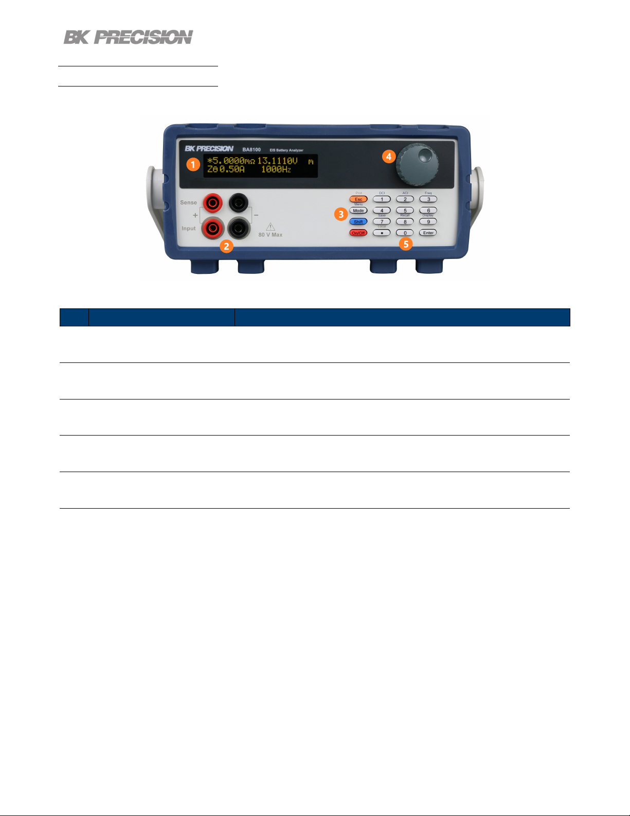
1.4 Front Panel Overview
The front panel interface allows for control of the unit.
Figure 1.2 Front Panel
General Information 11
Item Name
1 Display Visual presentation of the device function and measurements.
2 Input and Sense Connections Connection terminals for the provided Kelvin connection test leads.
3 Control Keys Includes Esc, Mode/Menu, Shift and On/O keys.
4 Rotary Knob Used to navigate menus, modes, and adjust parameters.
5 Numeric Keypad Provides a fast and precise input.
Table 1.1 Front Panel
Description
Page 12
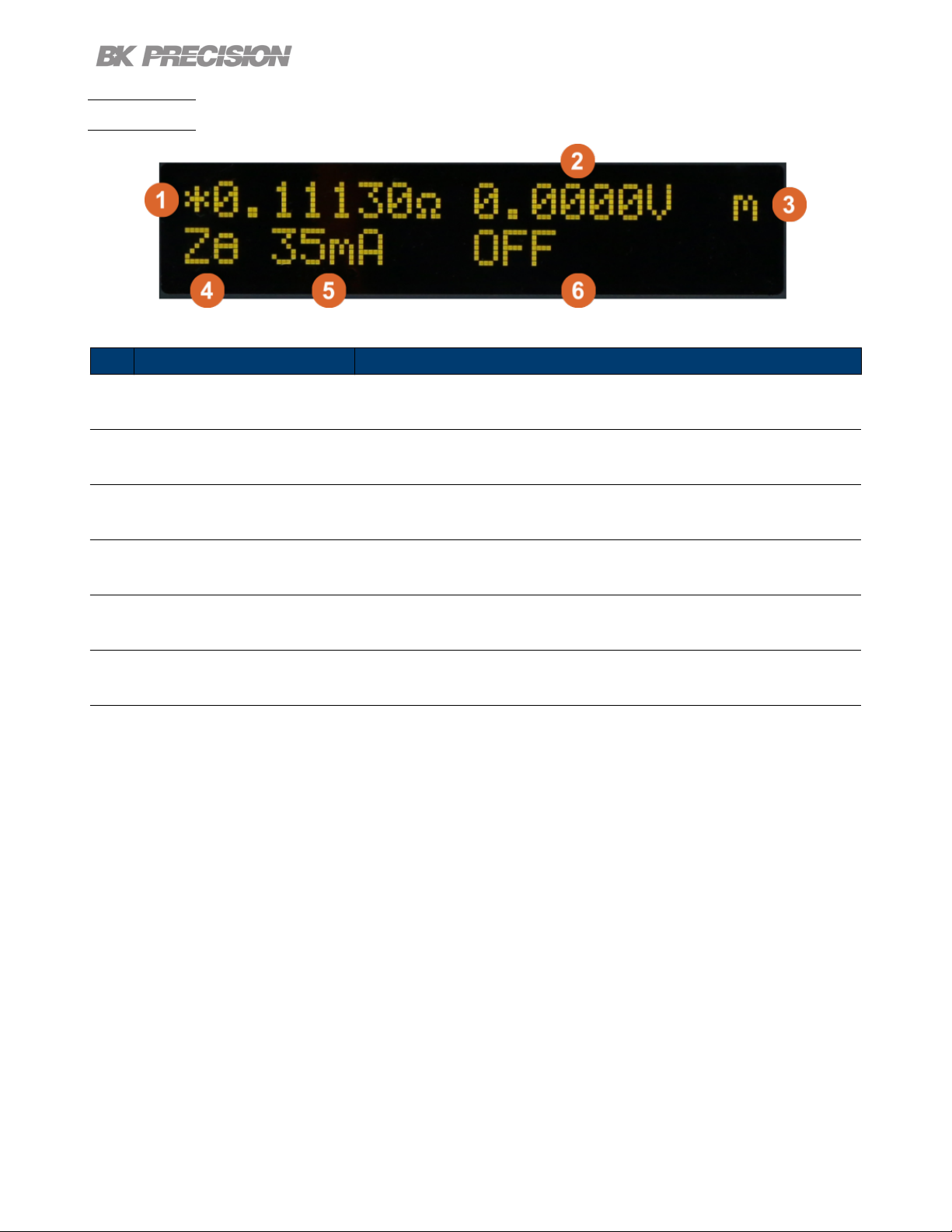
1.5 Display
General Information 12
Figure 1.3 Display
Item Name
1 Primary Measurement Displays the primary measurement value. See section 3 for more details.
2 Secondary Measurement Displays the secondary measurement value. See section 3 for more details.
3 Measurement Mode Displays the select measurement mode.
4 Primary Measurement Indicator Displays the selected primary mode.
5 Current Measurement Displays the load current.
6 Measurement State/Frequency Displays the frequency.
Table 1.2 Front Panel
Description
Page 13
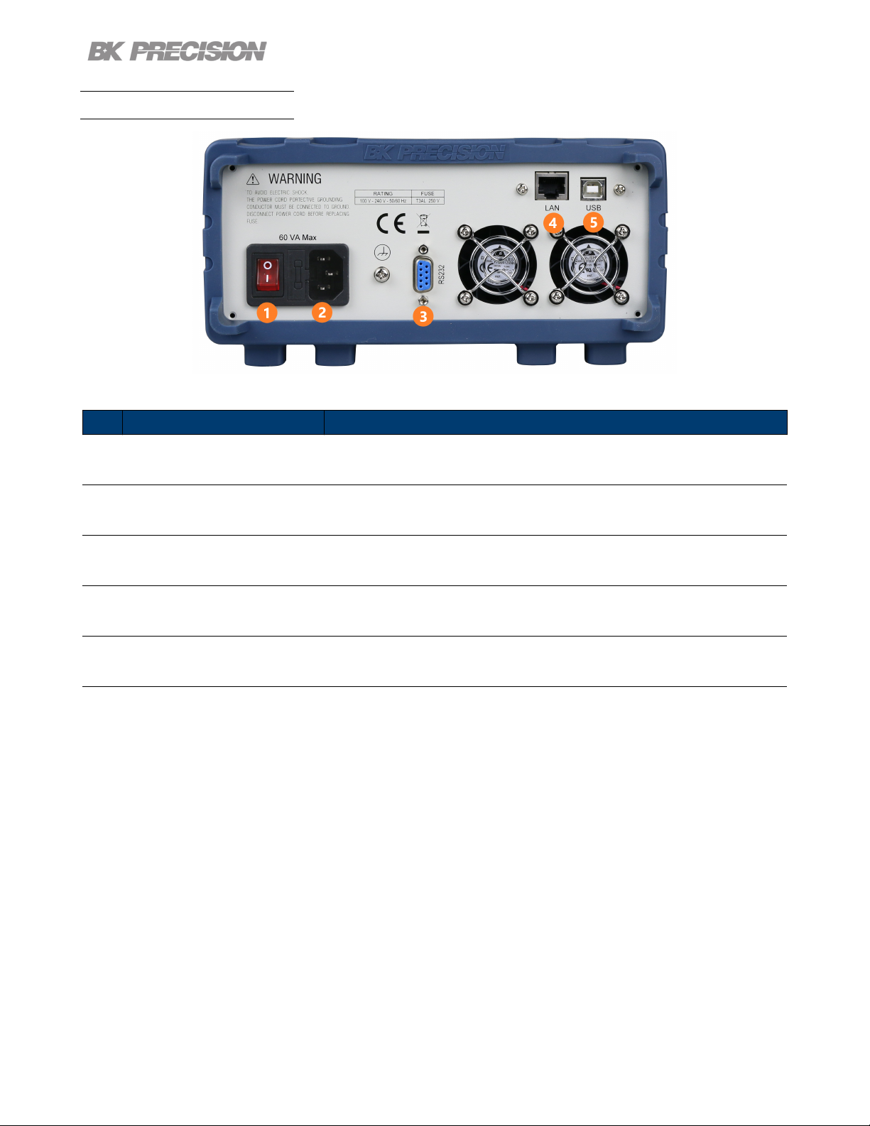
1.6 Rear Panel Overview
General Information 13
Figure 1.4 Rear Panel Overview
Item Name
1 Power Switch Powers the unit ON or OFF.
2
3 RS232 Connect a straight RS 232 cable to remotely control the unit.
4 LAN Connect an ethernet cable to remotely control the instrument.
5 USB Interface Connect a USB type B to type A to remotely control the unit.
AC Power Input
& Fuse Box
Houses the fuse as well as the AC input.
Table 1.3 Rear Panel
Description
Page 14

Getting Started
2.1 Input Power and Fuse Requirements
The supply has a universal AC input that accepts line voltage input within:
Voltage: 100 - 240 VAC (+/- 10 %)
Frequency: 50/60 Hz
Input Power: 60 VA MAX.
Before connecting to an AC outlet or external power source, be sure that the power
switch is in the OFF position. Verify that the AC power cord, including the extension line,
is compatible with the rated voltage/current. Once veried, connect the cable rmly.
The included AC power cord is safety certied for this instrument operating in rated range. To
change a cable or add an extension cable, be sure that it can meet the required power ratings
for this instrument. Any misuse with an uncertied AC power cord will void the warranty.
SHOCK HAZARD:
The power cord provides a chassis ground through a third conductor. Verify that your power
outlet is of the three-conductor type with the correct pin connected to earth ground.
Page 15

Getting Started 15
2.2 Fuse Requirements
An AC input fuse is necessary when powering the instrument. The table below shows the fuse required.
Fuse Specication
T3AL, 250 V
A second fuse can be found within the fuse box.
2.3 Fuse Replacement
For safety, no power should be applied to the instrument while changing line voltage
operation. Disconnect all cables connected to the instrument before proceeding.
Check and/or Change Fuse
• Locate the fuse box next to the AC input connector in the rear panel (see Figure 2)
• With a small at blade screwdriver, insert into the fuse box slit to pull and slide out the fuse box as indicated below.
• Check and replace fuse if necessary (see Table 2.1 - Fuse Table).
Figure 2.1 Fuse Removal
Disconnect power from the instrument when removing and installing fuses.
Any disassembling of the case or changing the fuse not performed by an
authorized service technician will void the warranty of the instrument.
Page 16

Getting Started 16
2.4 Theory of Operation
The BA8100 stimulates the DUT using a small amplitude and a precisely timed alternating current signal. The unit
compares the reference signal and the response signal. By measuring the current and voltage signal at various frequencies,
a spectrum of internal impedance is derived.
2.5 Connections
Figure 2.2 Front Panel
The unit uses 4 connections: "Input" (positive and negative) and "Sense" (positive and negative). The provided Kelvin
test leads are color coordinated to simplify connections.
2.6 Input
The "Input" connection carries the test current. “Input” consist of the lower pair of connectors, which can be dierentiated
by grey highlighting rings. The grey rings indicate the banana plugs with a gray shroud are connected there.
2.7 Sense
“Sense” consist of the upper pair connectors. It senses the signal at the connecting point. They do not carry current,
which helps eliminate the inuence of the cables on the measurement values.
Page 17

Measurement Modes
The BA8100 contains two measurement modes: primary mode and secondary mode. To enter primary and secondary
mode press the button then press the button. The letter m can be seen in to top right side of the
screen. The m species the current mode state. If blinking "M" is displayed the instrument is in secondary mode. If the
blinking "m" is displayed, then the instrument is in primary mode. In Figure 5.1 we can see the unit is in primary mode
Figure 3.1 Primary Measurement Mode
The following measurements can be obtained:
Measurement Description
DC Displays the battery’s DC voltage and current.
ZΘ Displays the impedance (magnitude)
Xs Series mode: Displays the real and imaginary impedance.
Xp Parallel mode: Displays the real and imaginary impedance.
Cs Series mode: Displays the resistance and capacitance.
Cp Parallel mode:Displays the resistance and capacitance.
Ls Series mode: Displays the resistance and inductance.
Lp Parallel mode:Displays the resistance and inductance.
QD Displays quality factor and dissipation factor.
VΘ Displays the voltage magnitude and phase.
IΘ Displays the current magnitude and phase
Vx Displays the voltage in cartesian form.
Ix Displays the current in cartesian form.
Table 3.1 Measurement Modes
Page 18

Measurement Setup
Follow the instructions in 2.5 to ensure cabling will not have a major impact on the measurements.
Note:
The sweep function as well as plot functions are only available through the BK-FRA software.
Only the measurements listed in Chapter 3 can be obtained through the unit’s display.
The following settings may be entered either through the front panel or through the remote interfaces.
4.1 Setting DC Current Level
The DC current component denes the load applied to the battery. Measurements of a battery at dierent test currents
provides more information about the battery. Dierent load currents may be necessary depending on the size of the
battery.
1. Press the button then press .
2. Enter the load current using the numeric keypad.
3. Press the button to conrm the set value.
4.2 Setting AC Current Level
The AC current component stimulates the battery. The amplitude of this signal is critical for accurate measurement
of the battery internal resistance. This value is directly related to the measureable voltage generated by the battery’s
internal resistance. Therefore, batteries with smaller internal resistance value require larger AC current test. For larger
internal resistances a large test signals will generate a large voltage signal. The input gain of the system needs to change
depending on the signal level.
1. Press the button then press .
2. Enter the AC stimulus current using the numeric keypad.
3. Press the button to conrm the set value.
Note:
The AC current level should be set to approximately 10% of the set DC Current level.
Page 19

Measurement Setup 19
4.3 Setting Frequency and Sweep
It is standard to test batteries at 1KHz. However, measurements across a range of frequencies provide more information
than a single resistance measurement (at steady state or DC loading). To test across a range of frequencies use sweep
mode. Sweep mode is only available through the software provided.
4.3.1 Single Frequency
1. Press the button then press .
2. Enter the AC frequency using the numeric keypad.
3. Press the button to conrm the set value.
4.3.2 Sweep Mode
To access sweep mode use the BK-FRA software. More information on installing the software in chapter 6.
Figure 4.1 demonstrates the congurable parameters in sweep mode.
Figure 4.1 Software Sweep Mode
• Start: Set the starting frequency of the sweep.
• Stop: Set the stopping frequency of the sweep.
• Step: Set the steps in the sweep. Only available in Control Panel
when Lin mode is set.
• dB: Set the start and stop frequency for a logarithmic sweep.
• Lin: Set the start, stop and step frequency for linear sweep.
• List: Create a custom sweep. A separate window will open allowing the
user to customize up to 40 steps in a sweep. See gure 4.2
• DC-SWEEP: Performs multiple frequency sweeps at user-dened load levels set
in Edit (10 sweeps max).
• LOG: Save the recorded data to selected path.
A sweep yields more information about the DUT. The data collected can be graphed and recorded. See section 6 for
details on how to graph the sweep and record the data.
Figure 4.2
Software List Mode
Page 20

Measurement Setup 20
Note:
As frequency increases, the physical arrangement of the test leads has a greater impact. Reduce the loop area
created by the test leads when working at higher frequencies to reduce the inductance of the cabling.
4.4 Making a Measurement
Once the appropriate stimulus values have been specied, connect the battery. Press to enable the load and the
stimulus signal. Press the button to cycle between the dierent measurement modes. See section 3 for more
details.
To take measurements using the sweep function see section 6.4.
Note:
Once you obtain a measurement press the button to disable the load
and the stimulus signal. This prevents the battery from being discharged.
Page 21

Verication Test
Figure 5.1 Self-Test Fixture
The Self-Test Fixture (TLC81) serves two functions: it veries the BA8100 meets the accuracy and resolution specications, and is used as a reference when a user calibration is conducted. A user calibration is a compensation procedure
used to reduce the impedance introduced by the test leads. It does not issue data to create a report or certicate of
calibration that conrms conformance with its specifcations.
The user calibration procedure can be completed to the front panel or to the test leads. The BA8100 uses a single
memory location to store the compensation data. This memory will be over written each time the user calibration is
completed. Therefore, prior to conducting a verication test the user calibration procedure must be completed to the
front panel.
Note:
Out of the box the compensation data stored in the memory will be for the front panel. It is
recommended a verication test is conducted to ensure the instrument is working as expected.
The Verication Procedure should be completed when the user has concerns with user calibration to the test leads
or if there is doubt about the the instrument’s calibration. If the Verication Procedure to the Front Panel does
not provide conforming result after completing a user calibration to the front panel, the unit must be sent back to be
calibrated.
Page 22

Verication Test 22
5.1 Verication Procedure
The verication procedure can be conducted to the front panel or to the test leads. Verication to the test leads should
be completed when there is a change in the position of the leads that can aect the impedance. Changes in looping,
tension, or enviromental pararemeters of the test leads can cause the compensation values to become obsolete.
If after completing a user calibration to the test leads the verication test to the leads is still failing, the next step is to
complete a user calibration to the front panel and conduct the verication procedure to the front panel. If the verication
to the front panel also fails the BA8100 will have to be sent in for repair and calibration.
Note:
The BA8100 along with the TLC81 when must be shipped together when sent in for repair or calibration.
Materials Required
• BA8100
• TLC81, Self-Test Fixture with matching serial number to the BA8100
• Power supply
– Any power with an output of 5 V and 3A is required.
Note:
The TLC81 is matched to the BA8100 by the manufacturer. If the TLC81 serial
number does not match the BA8100 serial number conctact the distributor.
Page 23

Verication Test 23
5.2 Verication Procedure to the Front Panel
5.2.1 Verication Setup
Before initiating the verication to the front panel verify that the last user calibration was completed to the front panel.
1. Set the BA8100 to Zθ mode.
2. Connect the TLC81 to the BA8100. The xture directly connects to the four inputs located in the front panel.
Note:
Verify the arrow on the TLC81 is facing up. If connected correctely
Figure 5.2 TLC81 Verication Measurement
3. Connect the power supply to the TLC81’s power input.
4. Set the power supply’s voltage to 5 V and the current limit to 3 A.
5. Set the DCI to 2 A and ACI to 200 mArms.
6. Enable the BA8100 and the power supply’s output.
7. If the unit is within calibration and functioning properly the measurement will fall between 4.9700 and 5.0300 mΩ
±
(0.5 % of reading + 5 μΩ).
Figure 5.3 TLC81 Verication Measurement
Page 24

Verication Test 24
5.3 Compensating to the Test Leads
5.3.1 Setup
Before initiating the verication to the test leads verify that the last user calibration was completed to the test leads.
1. Set the BA8100 to Zθ mode.
2. Connect the test leads to the BA8100.
Verify the leads are connected to the corresponding terminals.
See section Connections.
3. Clamp the alligator clips to corresponding plate. Ensure the clips are clamped to the corresponding side. Silkscreen
labeling instrucs how to clamp the test leads. See gure 5.4
Figure 5.4 Verication-Test to Test Leads
4. Connect the power supply to the TLC81’s power input.
5. Set the power supply’s voltage to 5 V and its current to set DCI of the BA8100 (Recomended load: .5 A).
6. Enable the BA8100 input and the power supply’s output.
7. If the unit is within calibration and functioning properly it will measure 5.0000 mΩ±(0.5 % of reading + 5 μΩ).
– The BA8100 is calibrated to the front panel. Calibration to the test leads is required in order to meet the
impedance measurement specications.
– Small changes in test lead position as well as environment changes can have an eect on the instrument reading.
The calibration and verication setup must be the same to meet specications. To perform a user calibration to
the test leads refer to section 5.4.1
Page 25

Verication Test 25
5.4 User Calibration
Conguration of the settings in calibration mode can change the unit’s
measurement accuracy. Only adjustments to the ACA Ratio should be made.
5.4.1 User Calibration to the Test Leads
To a user calibration to the test leads connect the leads front the front panel to the TLC81. Power the TLC81 using a
5 V 3 A source. Before starting the user calibration procedure ensure your setup is complete. Making adjustment to the
setup, such removing the twist in the test leads, will eect the calibration ratios. The setup should be similar to the one
shown in gure 5.5 with adjustments to position of the test leads.
The leads should be laid in the position that will be used for testing.
Figure 5.5 Self-Test Calibration Verication to Test Leads
1. Enter back-door mode by pressing + . Once you enter back-door "Zθ" will ash on the OLED.
2. Enter Calibration Menu by pressing + .
3. Use the rotary knob to navigate through the Calibration Menu.
4. Select ACA Ratio.
• Set the RUT value to 5.0000 mΩ.
• Press to begin the compensation adjustment.
– This process can take up to 5 mins to complete.
Page 26

Verication Test 26
5. Select LOF ACA Ratio.
• Set the RUT value to 5.0000 mΩ.
• Press to begin the compensation adjustment.
– This process can take up to 20 mins to complete.
6. After both ACA Ratio and LOF ACA Ratio have been adjusted select Save Data to save the new ratios.
7. To returns to previous menu press .
8. To exit Back-door press + .
9. Power cycle the instrument.
Note:
Calibrating to the test leads will modify the initial calibration to the
front panel. Verication to the front panel may not meet specication.
5.4.2 User Calibration to the Pront Panel
To calibrate the unit to the front panel the TLC81 must be connected to the front panel and powered by a 5 V 3 A
source.
Figure 5.6 Compensating to the Front Panel
1. Enter back-door mode by pressing + . Once you enter back-door "Zθ" will ash on the OLED.
2. Enter Calibration Menu by pressing + .
Page 27

Verication Test 27
3. Use the rotary knob to navigate through the Calibration Menu.
4. Select ACA Ratio.
• Set the RUT value to 5.0000 mΩ.
• Press to begin the compensation adjustment.
– This process can take up to 5 mins to complete.
5. Select LOF ACA Ratio.
• Set the RUT value to 5.0000 mΩ.
• Press to begin the compensation adjustment.
– This process can take up to 20 mins to complete.
6. After both ACA Ratio and LOF ACA Ratio have been adjusted select Save Data to save the new ratios.
7. To returns to previous menu press .
8. To exit Back-door press + .
Page 28

Operating Software
6.1 Software Installation
The software can be found in the BK Precision website under the product’s page Docs & Software tab.
Download the BK-FRA software and install it.
Before you launch the software:
1. Connect the BA8100 and PC using a USB cable.
2. Connect the BA8100 into an AC plug.
3. Turn on the power switch.
4. Open the Windows Device Manager. After a few minutes you should see the USB device manager installed,
and a COM Port will be assigned by Windows under Deveice Manager > Ports.
5. Take a note of the COM Port number.
6. Launch the software.
6.2 Interface Conguration
Once the interface conguration window opens:
1. Set the knob to the remote interfaced that will be used to control the instrument.
• Set the interface Parameters:
– RS-232: Set the COM Port to match the assigned port noted in the device manager, and the baudrate of
the instrument.
– TCP: Set the IP Address.
2. Click open to launch the software.
• The BA8100 Control Panel will launch as shown in Figure 6.1
Page 29

6.3 Control Panel
Operating Software 29
Figure 6.1 Control Panel
The Control Panel is seperated into 6 sections:
1. Frequency/Amplitude
2. Sweep
3. Analysis
4. Sample
5. Output Condition
6. Output State
6.3.1 Frequency/Amplitude
Set the parameters of the alternating current signal.
• Frequency: Sets the frequency of the AC signal making a single point measurement(sweep is disabled).
• DC(A): Sets the value of the steady state load applied to the battery. (3.00 A Max)
• AC(%): Sets the percentage ratio betweeen DC and AC signals. (16% Max)
• AC(A): Sets the level of signal that stimulates the battery.
Page 30

6.3.2 Sweep
• Start: Set the starting frequency of the sweep.
• Stop: Set the stopping frequency of the sweep.
• dB: Set the start and stop frequency for a logarithmic increment sweep.
• Lin: Set the start, stop and step frequency for linear increment sweep
based on the Step value set.
– Step: Set the frequency increment for each step of the sweep.
Only available when linear increments(Lin) mode is set.
• List: Create a custom sweep. A separate window will appear allowing
the customization of 40 steps in a sweep. See Figure 6.3
• DC-SWEEP: Enable multiple sweeps with dierent DCI and ACI
parameters.
– To congure the parameters of each sweep click Edit > DC/AC
Sweep.
Operating Software 30
– A seperate window will appear allowing for customization of 10
steps(sweeps). See Figure 6.4
• LOG: Enable logging of the collected data to selected path.
– Upon completing the sweep the File Save Dialog Window will appear.
– The default location is the BK-FRA folder created during installation.
See Figure 6.2
Figure 6.3 List Sweep
Figure 6.2 Save Log
Figure 6.4 DC/AC Sweep
Page 31

6.3.3 Analysis
• +-180/ +360: Switch the display format of all Degree measurements to
either +-180 or +360.
• Meter: Opens the Impedance Meter window.
– Clicking the MEAS. button will enable measurements.
– Displays the measurements that are currently being acquired by the
BA8100. See Figure 6.6.
• V&C: Opens the Voltage & Current window.
– Graphs the magnitude and pahse of the acquired AC voltage and current
in the frequency spectra. See Figure 6.5
Operating Software 31
Figure 6.5 Voltage & Current Graph Figure 6.6 Impedance Meter
Page 32

Operating Software 32
• Nyquist: Opens the Impedance Nyquist window.
– Graphs the real vs the imaginary part of the impedance as functions of freauency.
– Enabling Freq. Marker will display the frequency value at which the selected point was measured.
Figure 6.7 Impedance Nyquist
• Bode: Opens the Impedance Bode window.
– Graphs the phase shift and magnitude changes of impedance across the applied frequency range.
– Enabling Freq. Marker will dislpay the frequency value at which the selected point was measured.
– The parameters shown in Figure 6.8 can be graphed.
Figure 6.8 Bode Plot
Page 33

Operating Software 33
6.3.4 Sample
• Sec/Cycle Sets the dwell time of each step.
– Enabling Auto will set the dwell time based on the time required for the frequency to acquired data.
(Smaller frequencies require more time to acquire data.)
6.3.5 Output Condition
• AGC (Automatic Gain Compensation): Enable/disable automatic gain compensation.
• When disabled the Voltage and Current gain can manually be adjusted.
Note:
It is recommended AGC be set to automatic.
Output State
• Meas.: Enable/disable measurement acquisition.
• Sweep: Enable/disable sweep mode.
• ON/OFF: Enable/disable AC signal output.
6.4 Running the Test
MEAS, SWEEP, and On can be found at the bottom of the control panel.
Click the ON button enables the load and the stimulus signal.
Select the desired analysis.(Meter, Nyquist, V & C, or Bode)
Click the SWEEP button to start the sweep.
Click MEAS. button to continuously acquire measurements. These measurement can viewed in the meter but are
overwritten when a new measurement is taken. Clicking pause will end the measurement acquisition and display the last
measurement taken.
Disable the load after each measurement is complete to prevent the battery from being drained.
Page 34

6.5 Test Results
Operating Software 34
The sweep can be plotted in a Nyquist, Voltage and Current, or Bode plot. These plots must be analyzed to interpret
various parameters of the DUT.
Page 35

6.6 Data Logging
Operating Software 35
Check the LOG box to record the data collected. The box is highlighted blue when checked. The le path can be set
once the sweep elapse. The data is saved as a .CSV le.
Page 36

System Setup
Press the button then press the button to enter the system menu. Use the rotary knob to navigate
between each menu and setting. The button integrated in the knob navigates up one menu level if available. Press the
button to enter the selected menu.
+ Indicates there are more items within the selected menu item.
= Indicates there are no further items within the selected menu item.
Pressing navigates into the menu where the setting value is changed or viewed.
7.1 Menu
Input Settings Load/stimulus input section settings
Display Settings Select format and unit of parameters.
I/O Cong Select remote interface.
Protection Set protection settings.
System Setup Set system setup settings.
7.1.1 Input Settings
AGC Automatic gain compensation.
Default: ON
Sample Interval Measurement period between samples
Default: 199ms
Auto Sample Automatically sample points
Default: ON
Current Gain Current measurement sensitivity (gain)
Default: x450
Voltage Gain Voltage measurement sensitivity (gain)
Default: x450
7.1.2 Display Settings
Phase Format Phase angle display format.±180 or 360 degrees
Default:±180
Page 37

7.1.3 I/O Conguration
RS232 Baud Rate RS-232 communication speed (4800, 9600, 19200, 38400, 57600, 115200)
Default: 9600
Term Character Serial transmission termination character. Carriage return (CR), Line Feed (LF)
or both (CR+LF).
Default: CR + LF
Network Ethernet/LAN settings. DHCP is not supported.
• IP Address
• Gateway IP
• Subnet Mask
7.1.4 Protection
Auto Cut-O Automatically turn o the input after a given time.
Default: OFF
System Setup 37
UV Protection Under-voltage protection - shuts o the input when the voltage reaches the limit.
OV Protection Over-voltage protection - shuts o the input when the voltage reaches the limit.
7.1.5 System Setup
Beeper Key beep - ON or OFF
Clear Memory Clear all data.
Security Code Set a security code.
Key Lock Lock the keys in the front panel.
Note:
Default: 00.00V
Default: 88.00V
Default: ON
Operation Time can be view by pressing +
.
Page 38

Remote Interface
The BA8100 can be remotely controlled over the USBVCP, RS232, or LAN.
To control the instrument using the FRA operation software provided by BK Precision:
1. Install the FRA software and NI VISA.
– Follow the instructions given in Ch 6.
2. Connect the device interface at the rear panel of BA8100 Series with a PC via a USB,RS232, or LAN.
Note:
The BA8100 automatically switches to active remote interface when connected to remote interface.
8.1 USBVCP
The Port Settings are as followed:
Baud rate: 9600
Data bits: 8
Parity: None
Stop bits: 1
Flow control: None
8.2 RS-232
A crossover cable is required to establish communication.
The baudrate is congured in the “I/O Cong” menu.
8.3 Ethernet
This interface is congured in the “I/O Cong” menu.
Telnet and rawsocket are supported over port 3000.
8.4 Local and Remote Mode
When using the analyzer via a remote interface, the keypad is locked out. To re-enable
local control, press .
Page 39

EIS Battery Analyzer
bkprecision.com
BA8100
Specifications
Note: All specifications apply to the unit after a temperature stabilization time of 30 minutes over an ambient temperature range of 23 °C ± 5 °C.
BA8100
Input
Voltage 0.5 V to 80 V
Power 200 W maximum (dissipated by internal load)
Settings
Current
Modulating AC Current 50 mArms to 300 mArms (10% of DCA typical)
Modulating Frequency
Displayed Parameters
Primary X, Z, V, I, Freq.
Secondary
Measurements
Voltage 4-wire
Accuracy (ACI = 0)
DC Sink Current
Accuracy (ACI = 0)
Resistance R
Auto sampling interval (8 to 10 cycles)
and auto range enabled
Accuracy (10 Hz to 10 kHz) ±(0.5% of reading + 5 µΩ)
Impedance Z
Auto sampling interval (8 to 10 cycles)
and auto range enabled
Accuracy (10 Hz to 10 kHz) ±(0.5% of reading + 5 µΩ)
Phase Angle θ
General
AC Input 100 VAC to 240 VAC, 50/60 Hz
UUT Connector 4-terminal banana jack
I/O Interfaces LAN, USB (Virtual COM), RS232
Operating Temperature 32° F to 104° F (0° C to 40° C)
Storage Temperature 14° F to 122° F (-10° C to 50° C)
Dimension (W x H x D) 8.5 “ x 3.5” x 14.6” (215 x 90 x 370 mm)
Weight 9.9 lbs (4.5 kg)
Software Bundled software for fixed or frequency sweep, Nyquist and Bode plots
Warranty 3 Years
Standard Accessories
(1) The accuracy of DC voltage and current should be under no modulation condition (i.e. AC current = 0).
DC 0.5 A to 3 A (dissipated by internal load)
Range 0.05 Hz to 10 kHz
Resolution (Auto) 0.001 Hz to 0.1 Hz
Accuracy 0.01% of setting
Rs, Rp, Xs, Xp, Cs, Cp, Ls, Lp, Q, D, and θ
Range 0 V to 80 V
Resolution 0.1 mV
(1)
0.05% of reading + 0.05% of full scale
Range 0 A to 3 A
Resolution 0.1 mA
(1)
0.5% of reading + 0.1% of full scale
Displayed Digits 5 digits including sign
Resolution 1 µΩ
Displayed Digits 5 digits including sign
Resolution 1 µΩ
Range -180° to 180°
Resolution 0.01°
Accuracy ±0.3°
Power cord, kelvin clip test leads, calibration certificate,
calibration test fixture (TLC81)
5
v042722
Page 40

Service Information
Warranty Service: Please go to the support and service section on our website at bkprecision.com to obtain an RMA
#. Return the product in the original packaging with proof of purchase to the address below. Clearly state on the RMA
the performance problem and return any leads, probes, connectors and accessories that you are using with the device.
Non-Warranty Service: Please go to the support and service section on our website at bkprecision.com to obtain an
RMA #. Return the product in the original packaging to the address below. Clearly state on the RMA the performance
problem and return any leads, probes, connectors and accessories that you are using with the device. Customers not on
an open account must include payment in the form of a money order or credit card. For the most current repair charges
please refer to the service and support section on our website.
Return all merchandise to B&K Precision Corp. with prepaid shipping. The at-rate repair charge for Non-Warranty
Service does not include return shipping. Return shipping to locations in North America is included for Warranty Service.
For overnight shipments and non-North American shipping fees please contact B&K Precision Corp.
Include with the returned instrument your complete return shipping address, contact name, phone number and description
of problem.
B&K Precision Corp.
: 22820 Savi Ranch Parkway
Yorba Linda, CA 92887
bkprecision.com
714-921-9095
Page 41

LIMITED THREE-YEAR WARRANTY
B&K Precision Corp. warrants to the original purchaser that its products and the component parts thereof, will be free
from defects in workmanship and materials for a period of three years from date of purchase.
B&K Precision Corp. will, without charge, repair or replace, at its option, defective product or component parts. Returned
product must be accompanied by proof of the purchase date in the form of a sales receipt.
To help us better serve you, please complete the warranty registration for your new instrument via our website www.bkprecision.com
Exclusions: This warranty does not apply in the event of misuse or abuse of the product or as a result of
unauthorized alterations or repairs. The warranty is void if the serial number is altered, defaced or removed.
B&K Precision Corp. shall not be liable for any consequential damages, including without limitation damages resulting
from loss of use. Some states do not allow limitations of incidental or consequential damages. So the above limitation
or exclusion may not apply to you.
This warranty gives you specic rights and you may have other rights, which vary from state-to-state.
B&K Precision Corp.
22820 Savi Ranch Parkway
Yorba Linda, CA 92887
www.bkprecision.com
714-921-9095
Version: May 19, 2022
 Loading...