

Page 1

Model 830B & 890B Capacitance Meters
Page 2

-II--III
Page 3

-
Limited Three-YearWarranty
B&K Precision Corp. warrants to the original purchaser that its products and the component
partsthereof, will be free from defects in workmanship and materialsfor a period of three
yearsfrom date of purchase.
B&K Precision Corp. will, without charge, repair or replace,at itsoption, defective product or
component parts. Returned productmust be accompanied by proof of the purchase date in
the form of a salesreceipt.
To obtain warranty coverage in the U.S.A., thisproduct must be registered by completing a
warranty registration form on www.bkprecision.com within fifteen (15) days of purchase.
Exclusions: This warranty does not apply in the event of misuse or abuse of the
product or as a result of unauthorizedalterations or repairs. Thewarranty is void if the
serial number is altered, defaced or removed.
B&K Precision Corp. shall not be liable for anyconsequential damages, including without
limitation damages resulting from lossof use. Some states do not allow limitations of
incidental or consequential damages. So the above limitation or exclusion may not apply to
you.
This warrantygivesyou specific rightsand you may have other rights, which vary from stateto-state.
B&K Precision Corp.
22820 Savi Ranch Parkway
Yorba Linda, CA 92887
www.bkprecision.com
714-921-9095
Page 4

-IV-
Contents
SAFETY INFORMATION.........................................................................................1
QUICK START............................................................................................................3
CAPACITANCE METERS........................................................................................4
INTRODUCTION...............................................................................................4
GETTING START WITH YOUR METER..............................................................5
DISPLAYILLUSTRATION..................................................................................5
TERMINALS.....................................................................................................7
PUSH-BUTTONOPERATIONS............................................................................8
POWER-ON OPTION ..............................................................................................12
DEMONSTRATE DISPLAY INDICATORS...........................................................12
DEFAULT FACTORYHI/LOSETTING..............................................................12
HOW TO ENTER SETUP MODE...........................................................................13
FACTORY DEFAULT.......................................................................................14
BAUD RATE...................................................................................................15
PARITYCHECK..............................................................................................16
DATA BIT......................................................................................................16
ECHO.............................................................................................................17
PRINT ONLY..................................................................................................17
BEEP FREQUENCY.........................................................................................18
LOCK BUTTONS.............................................................................................19
AUTOPOWEROFF.........................................................................................20
BACKLIT DISPLAY.........................................................................................21
BRIGHT LEVEL OF BACK-LIT FOROFFSTATE................................................22
BRIGHT LEVEL OF BACK-LIT FORONSTATE.................................................23
RESET TO DEFAULT.......................................................................................24
CALCULATION FUNCTION .................................................................................25
STATIC RECORDING......................................................................................25
DATAHOLD/TRIGGER HOLD........................................................................27
RELATIVE(ZERO).........................................................................................28
TOLERANCEMODE.......................................................................................30
COMPAREMODE ( )................................................................................32
REMOTE COMMUNICATION..............................................................................38
Page 5

-V-
CAPACITANCEMEASUREMENT .......................................................................40
CALIBRATING THE METER................................................................................42
INTRODUCTION.............................................................................................42
ENVIRONMENTAL CONDITION.......................................................................42
WARM UP......................................................................................................42
RECOMMENDEDTEST EQUIPMENT.................................................................43
SPECIFICATIONS....................................................................................................44
GENERAL SPECIFICATION..............................................................................44
ELECTRICALSPECIFICATIONS........................................................................46
MAINTENANCE.......................................................................................................47
SERVICE........................................................................................................47
BATTERY REPLACEMENT...............................................................................48
CLEANING.....................................................................................................49
Page 6
-1-
SAFETY INFORMATION
These meters are hand-held, battery-operated instruments for testing and
sorting capacitors.
AWARNINGidentifies conditions and actions that maycause hazard(s) to the
user; a CAUTION identifies conditions and actions that may damage this
Device. Following Table-1 explain international electrical symbols used on
this meter.
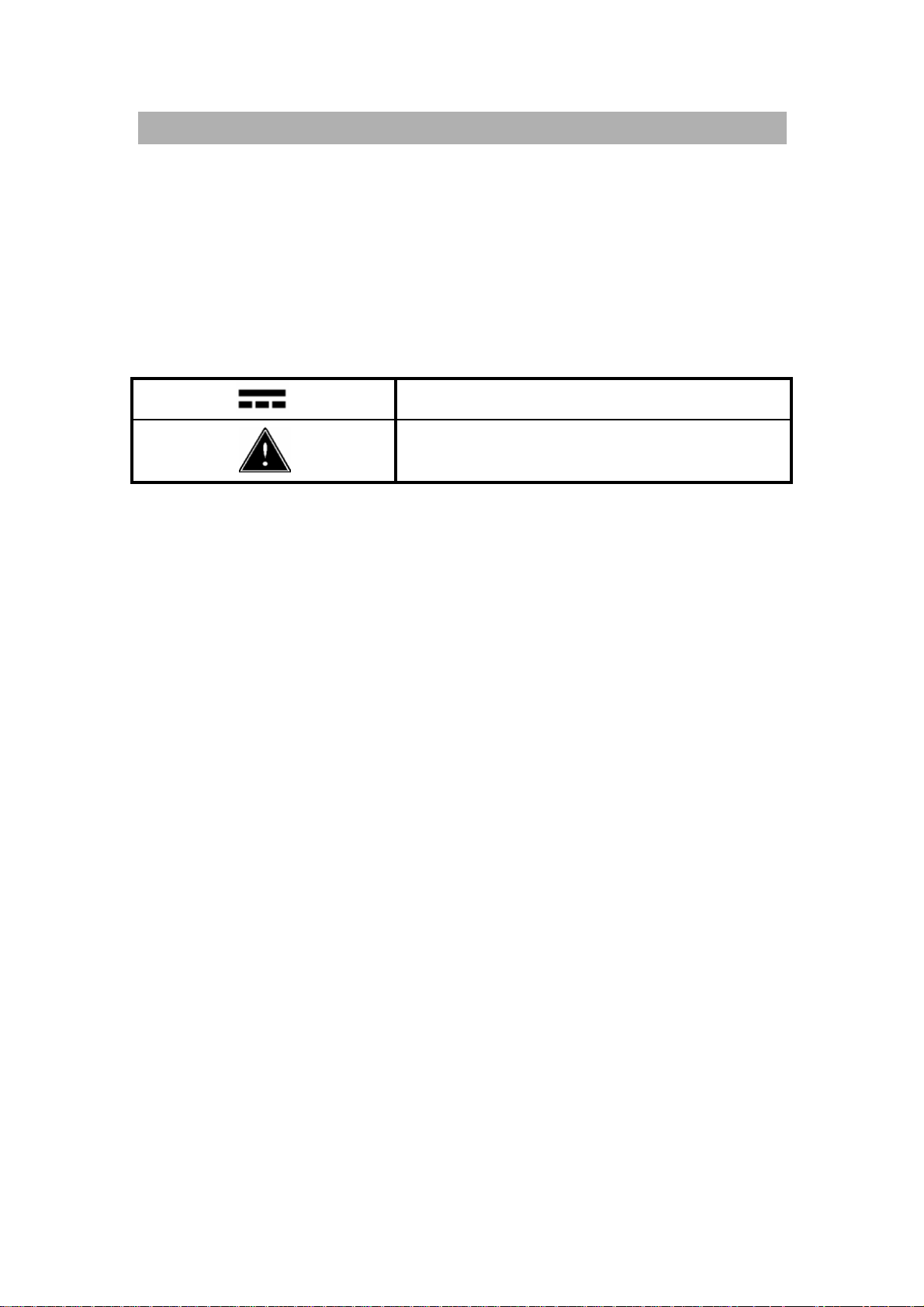
Table- 1 International Electrical Symbols
DC - Direct Current
Caution,risk of danger
(See Explanation In The Manual)
Page 7

-2-
SAFETY INFORMATION
Warnings and Cautions
Toavoid electric shock, injury, or damage to this instrument andensure
that you use the meter safely,follow the safety guidelines listed below:
Read this operationmanual completelybefore using this device and follow
all safetyinstructions.
This device is for indoor use,altitude up to 2,000m.
Avoid working alone.
Use the device onlyas specified in this manual; otherwise, the protection
provided bythe metermaybe impaired.
Never measure Voltage with this meter.
Do not use this device ifitlooks damaged.
Inspectthe leads for damaged insulation or exposed metal.Replace
damaged leads.
Disconnect the power and discharge all high-voltage capacitors before
testing.
Be cautions when working above 70V DC or 33VRMS and 46.7V peak,
such voltages maycause ashock hazard.
Always use specified battery.
The meter is designed in compliance with EN61010 (IEC1010-1)
Installation Category 50V Pollution Degree 2.
CE requirement: Under the influence of RF field according to standard, the
supplied test leads will pick up induced noise. To have better shielding
effect,a short-twisted leadshould be used.
Page 8
-3-
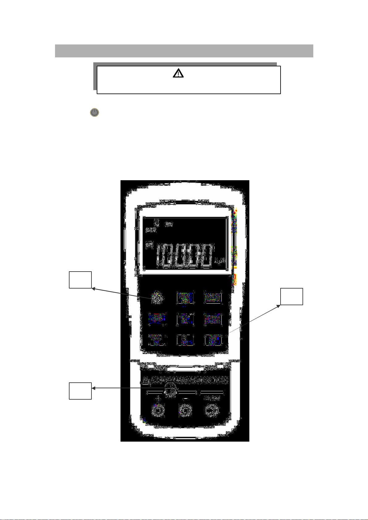
QUICK START
WARNING
Read "SAFETY INFORMATION" before using this device.
1. Push to turn on the meter.
2. Push REL to subtract the residual capacitance as not yet insert capacitor
into sockets and terminals.
3. Insert the leads of capacitor into "+" and "-" inputsockets, respectively.
4. Be sure the polarityfor capacitor and remove your hands from capacitor
to be tested.
5. Read the display.
1
2
3
Figure- 1 Capacitance measurement
Page 9

-4-
CAPACITANCE METERS
you to sort the
for High / Low Limit setting, included
volatile memory inside, will keep your setting even the power
ding, you will know maximum, average and minimum
the difference between a
th SCPI commands will
Introduction
These meters are uniquelydesigned for capacitor sorting and measuring.
Theyare fullyauto ranging 11000 count meters. Manual ranging can be
selected via the front push button.
Main Features:
Auto-range, 11000 count resolution and large LCD withdual display.
Wide range resolution and measurement from 0.1pF to 199.99 mF
(50.00mFfor model 890B).
Visible and audible Tolerance mode assists
capacitor.
Comparison mode with25 sets
nonoff.
Static Recor
values without calculator.
Relative mode will help you to calculate
standard anda measuring value.
Data Hold with Manual or Auto Trigger
Bi-directional optic computer interface wi
assist you to a specialist and make report easier.
Low battery indication
Brightness LED backlight
Safe, precisionandspeed closed case calibration
Page 10
-5-
GETTING START WITH YOUR METER
Primarydisplay
(1stdisplay) for
Tolerance
“C”
flashing
Static recording mode for
Relativ
e
DH:data hold
Alerting for tolerance
% is unit for
Unit for
Capacitance
Auto
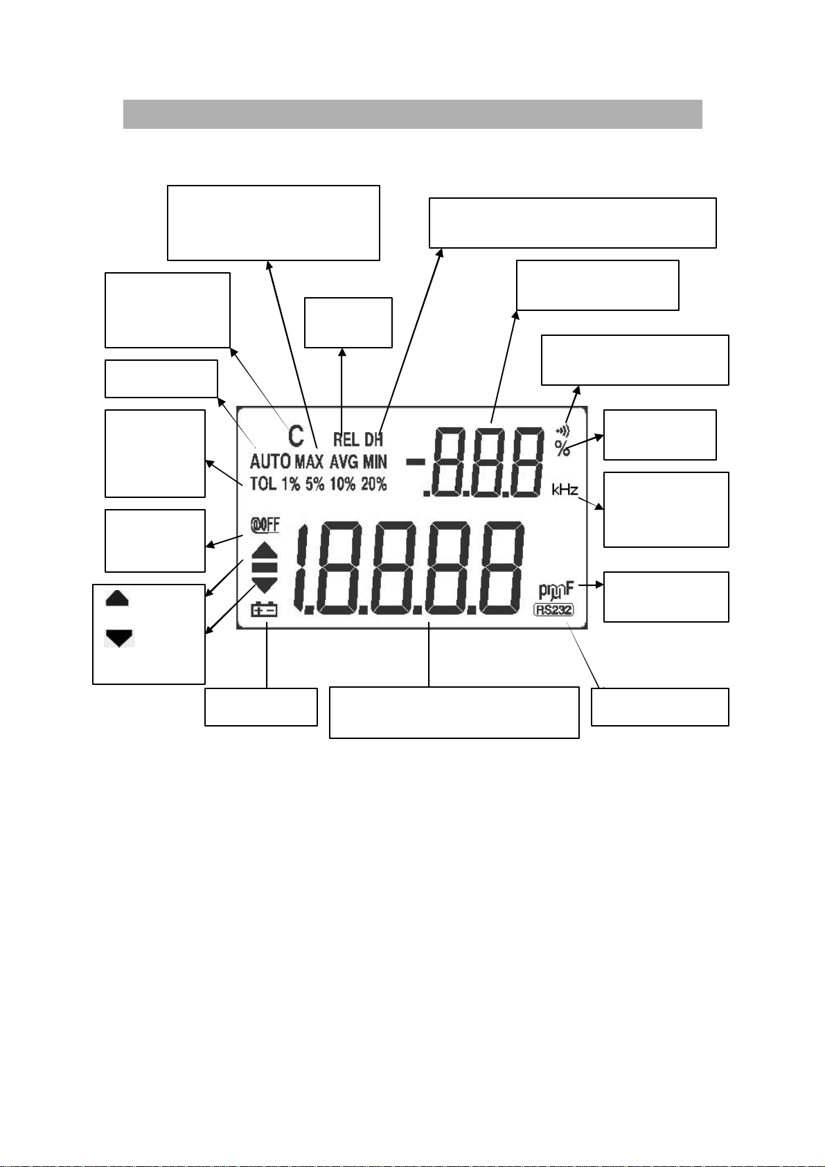
Display Illustration
for charging
capacitor
Auto range
mode for
1%, 5%,
10%, 20%
power off
: Over
High limit
:Under
Low limit
MAX, MIN, AVG and
Present (MAXAVGMIN)
mode
“DH” flashing means under trigger.
Secondary display
and compare mode
tolerance
Beeper
frequency
units
capacitance measurement
Figure- 2 LCD Display
Remote controlLow battery
Page 11
-6-
Item
1)
4)
5)
6)
8)
10)
11)
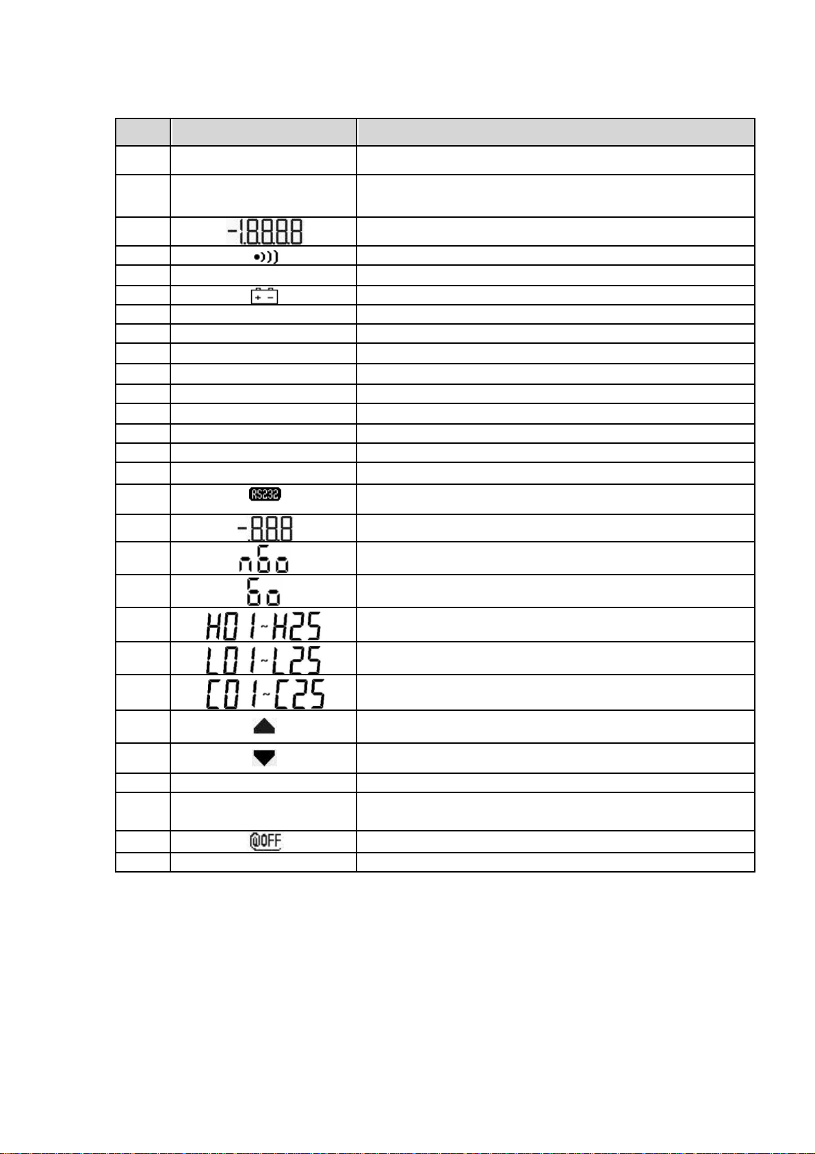
Indicator Description
AUTO AUTO range
2) TOL 1%5% 10%20%
3)
DH Data hold
7) REL Relative mode
pF 1/1000,000,000,000 Farad
9) nF 1/1000,000,000 Farad
F
mF 1/1000 Farad
12) MAX AVGMIN Static recording mode, indicates the present reading
13) MAX Maximum reading
14) AVG Average reading
15) MIN Minimum reading
16) Remote control
17) Secondary display(2nddisplay).
18) Reading out of the HI/LO limits
Tolerance mode, to set1%, 5%,10% and 20% for
sorting capacitance.
Primarydisplay(1stdisplay).
Audible alertfor tolerance or comparemode
Low batteryindication.
1/1000,000Farad
19) Reading within the HI/LO limits
20) The primarydisplayshows HI limitsetting
21) The primarydisplayshows LO limitsetting
22) Displaythe HI/LO limitset for compare mode.
23) Reading out of the HI limit
24) Reading out of the LO limit
25) % Unit for tolerance display.
26) C
27) Enable Auto power off
28) kHz Unit for Beeper Frequencyas setup mode
Charging period will be flashed,displayas
discharging period.
Page 12
-7-
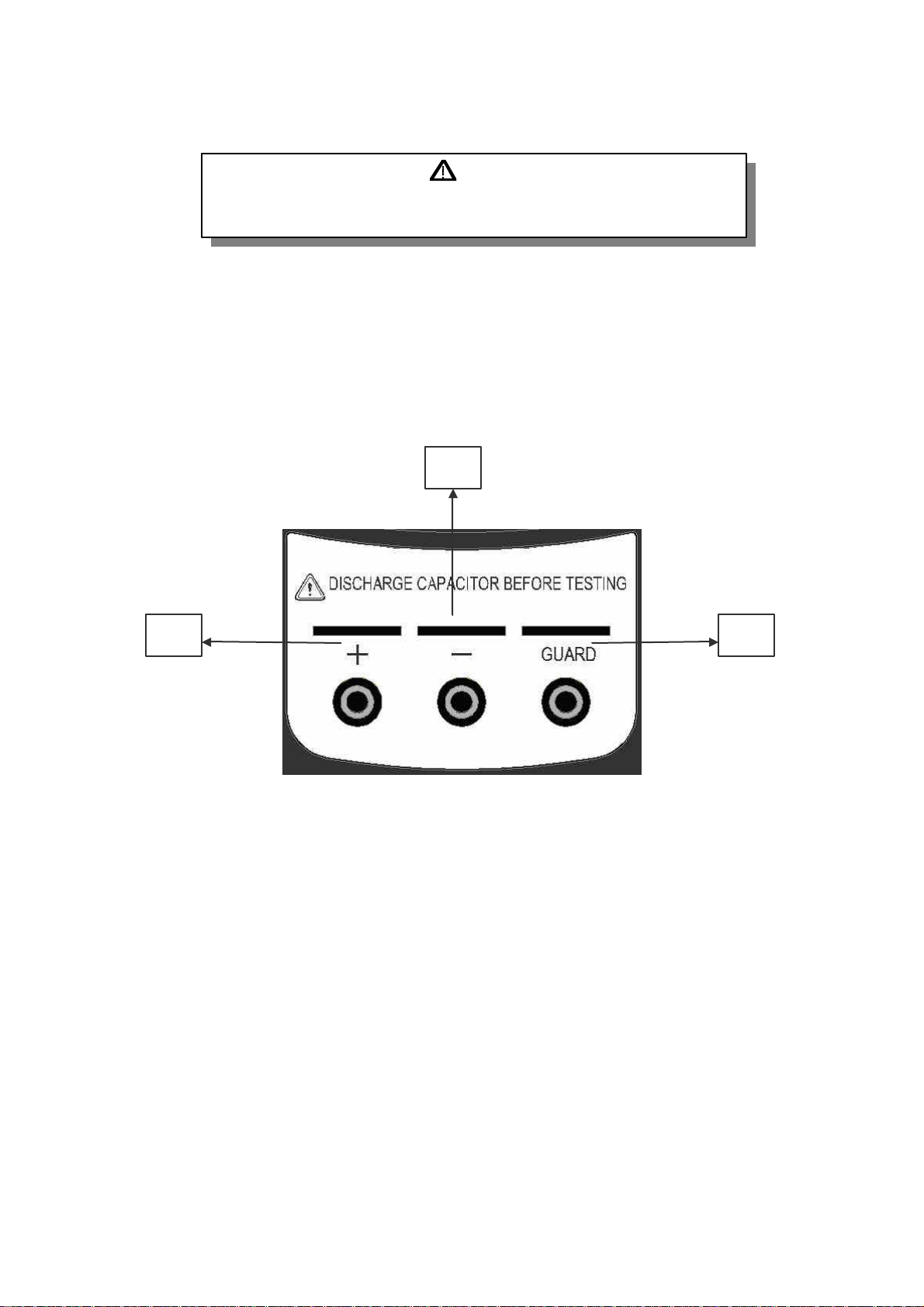
Terminals
WARNING
To avoid damaging this device, discharge the capacitor before
testing. Be sure the polarity for capacitance measurement
To avoid damaging this meter, do not exceed the input limit. Do not apply
voltage to input terminals. Discharge the capacitor before testing.
1) Positive terminal/ socket
2) Negative terminal/socket
3) Guard terminal/ socket
2
1
3
Figure- 3 Terminals
Page 13
-8-
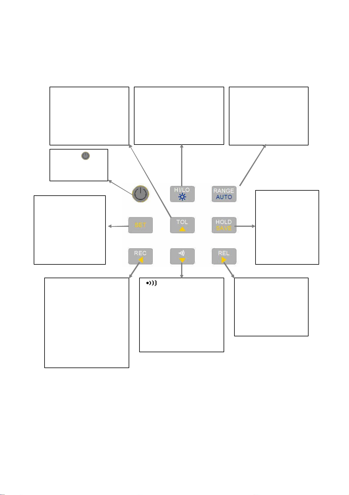
Push-button operations
RANGE:
Change
TOL
:
Press to set
HI/LO:
To setor see
Set:Press and hold
H
OLD
:
Freeze
REL:
Set the value
REC
:
Press to
set
:
Push to enter
The operation of push-button is shown as below. When push the button,
a related symbol will be lit, and the beeper will sound.
Tolerance mode, and
select 1%,2%, 5%,
10% and 20 %. Press
and hold for > 1 Sec.
to quit tolerance mode
POWER : To
turn ON/OFF
the meter.
for more than 1
sec. to toggle HI/LO
limit setting.Push
to select which set
will be adjusted as
setting mode
HI/LO limits as setting
mode or comparemode
:Press and hold for > 1
Sec. to toggle backlit
ON/OFF
measuring range.
AUTO:Press and
hold for > 1 Sec. to
set Auto-range
measuring value.
Press again to
trigger next
measuring value
Press and hold
for > 1 Sec. to
exit trigger hold.
Static recording mode.
Press this button
momentarilyto cycle
through MAX,MIN,
AVGand present(MAX
MIN AVG) readings at
recordingmode. Press
and hold for > 1 Sec. to
quite recording mode.
comparemode. Press
and hold for > 1 Sec. to
quite compare mode.
As comparemode,
press again to select
which HI/LO limits to be
compared.
Figure- 4 Pushbuttons
on the displayto be
subtracted.
Press and hold for
>1 sec. to quit
relative mode.
Page 14

-9-
1. :Power ON or OFF
This button is used to toggle the power ON or OFF for the meter. Be
sure to press button completelyto be locked or released.
2. HOLD:Data Hold
Press the button to enable the data hold function. The function allows
operator to hold the displayed digital value.
Press this button momentarilyto trigger holding next reading.
Press this button for more than 1 second to exit the mode.
3. REC: Static Recording
Press "REC"button to enable the recording function.
Press "REC" button momentarily to cycle through maximum, minimum,
average and present readings. The MAX, MIN, AVG or MAX AVG MIN
indicator turns on respectively to indicate which value is being
displayed.
Press "REC"button for more than 1 second to exit the recording mode.
The beeper sounds a tone when a new MAX or MIN value has been
recorded.
The static recording capturesstable values and updates the memory; it
will notrecord the values are “OL” (overload) or below 10 count value.
4. REL: Relative function
The function shows the difference between the measured value and
the offset reference value.The displaymay show a non-zero value due
to the presence of test leads. You can use the relative function to nullify
the residual.
Press “REL” button to enable the relative function, and the "REL" sign
will be displayed. Press “REL” button again to renew relative value
again.
Press “REL” button for more than 1 second to exit the mode.
The relative function can operate in both auto and manual ranging
mode but the function cannotbe setwhen an overload value exists.
5. RANGE: Auto/ Manual Range
Press this button to select manual range and turn off the "AUTO"
indicator.Press this button momentarilyto step up a range ata time.
In auto-range, the "AUTO" indicator is lit and the meter will select an
appropriate range for resolution if a reading is greater than maximum
available range, "OL" (overload) will be displayed on the display. The
meter will select a lower range when reading is less than about 9 of
full scale.
Press this button for more than 1 second to select auto-range.
Page 15
-10-
6. TOL: Tolerancemode
With capacitor into the terminals, press the "TOL" button to enable the
tolerance mode and set the display value to be a standard reference.
The “TOL” indicator will be indicated, and tolerance will be indicated on
the secondarydisplay. The meter range is locked also.
Press the “TOL” button momentarily again to cycle through 1%, 5%,
10% and 20% tolerance as desire. The alerting sign of “ ” will be
indicated accompanying. The beeper sounds a tone while the test
value is within the selected tolerance. If the test value is out of the
selected tolerance,the beeper will sound three tones.
This mode can not be enabled under following condition:
a. After setting the recording mode.
b. After setting the Comparemode.
c. The displayshows either OL or below 10 counts.
Press and hold this button for more than 1 second to exit tolerance
mode.
7. :Compare Mode
Press this button to enable the compare mode. The measuring range is
locked in this mode. The “ “ indicator will be shown, and the
secondary display will indicate “C # #” meaning which set has been
used for compare mode. The two right digits indicate current compare
set. The “# #” is from 01 to 25. The primary display shows the present
measurement.In this state, it is readyfor testing. If the reading is out of
the high limit (Sign “ “ lit) and the low limit (Sign” “ lit), three
tones will be sounded, also the secondary display indicates “nGo”. If
the reading is within the high and the low limits, the beeper sounds a
tone, and the secondary display indicates “Go”. After 3 seconds or the
reading lower than 10 counts, the meter will return to readystate.
Press this button momentarily to select different settings for compare.
The secondary display will indicate “C01” to ”C25” according to which
comparison record has been selected. You can press and hold SAVE
button for more than one second to save comparisonsetfor next entry.
Press this button for more than 1 second to exit the mode.
8. HI/LO:High/Low limits
Press this button momentarily to see the High/Low limit value to be
used as compare mode. Press this button to cycle through High limit,
Low limitand present values on primarydisplay. The secondarydisplay
showed as “H # #”, “L # #” and “C # #” respectively. After 3 seconds
without pressing this button again, it will return present value display.
In the High/ Low limit setting mode, press this button momentarily to
toggle HI and LO limits for adjustment.
Page 16

-11-
9. SET: sethigh/low limits for compare mode
Press the SET button for more than 1 second to enter the HI/LO limit
setting mode. The secondary display will flash “H01” and the primary
display will indicate the value of High limit. Following buttons will be
used for this setting mode:
a. (LEFT) or (RIGHT):select which digit will be adjusted.
b. (UP)or (DOWN): to Increase or decrease the current digit
value.
c. HI/LO: Select High or Low limit to be set.
d. SAVE:Press this button for more than 1 second to store the
setting value into the memory. The beeper will sound two tones
means theselected value has been stored. Ifthe current setting
can’t meetthe rule that the high limit mustequal or greater than
the low limit, the beeper sounds three tones (“BE-BE-BE”).
e. SET: Select next comparesetting. Press this button momentarily
to cycle through L01 (or H01) to L25 (or H25) then come back to
L01 (H01) setting.
Press the SET button again for more than 1 second to exit the HI/LO
limit setting mode.
10. Back-Lit
Press this button for more than 1 second to toggle backlit ON/ OFF.
Backlit turns off automaticallyafter setting period bysetup mode.
Page 17
-12-
POWER-ON OPTION
To selectpower-on options, press and hold the pushbutton while turning the
ON/OFF switch to on position. These power-on options are listed in below
table:
Table- 2 Power-ONOptions
PUSHBUTTON DESCRIPTION
HOLD Demonstrate Indicators
To demonstrate the indicators, the entire indicators will be
displayed. Press anybutton to exitdemonstration mode.
Reset the high and the low limits tomanufacture's default
values.
RANGE Fast power off test for manufacture purpose
REL To see the firmware version
Setup mode
SET
Demonstrate display indicators
Configure related parameter,please refer to how to enter
setup mode for detail.
To demonstrate the indicators, press the HOLD button and turn on the meter
simultaneously. All indicators will be displayed. Press any button to exit
demonstrationmode.
Default factory HI/LO setting
To setthe high and the low limits tomanufacture's default values.
Page 18

-13-
HOW TO ENTER SETUP MODE
Press and hold SET button, then turn on the meter from OFF. Release push
button when you hear a tone, the meter will enter setup mode then. These
parameters will be remained in non-versatile memoryeven the meter is turned
off. You can configure related parameters on setup mode by following
procedures:
1. Press (LEFT) or (RIGHT) button to selectwhich menu item to
be set.
2. Press (UP) or (DOWN) button to change the parameter.
3. Press “SET” button to select which digit to be adjust,the selected
digit will be flashed.
4. Press and hold “SAVE” button for more than onesecond to save
your setting.
5. Push “SET” button for more than onesecond to exit setupmode.
Page 19

-14-
Factory Default
FF” means to disable turning
Following Table describes the outline of the setup menu item and indicates
the factory settings.
Table- 3 Descriptions for Outline of Setup Menu Item
Menu item
bAUd 9600 Baud rate: 2400, 4800, 9600, 19200
PArt none Parity: odd, even or none
Data 8-b 8 bits or 7 bits (Stop bit is always 1 bit)
Echo oFF Echo: “on” or “oFF”
Prnt oFF Print:“on” or “oFF”
beep 4800
LbUt oFF
AoFF 15
blit 30
Factory
Setting
Selectable Parameters
Driving frequency:4800, 2400, 1200, 600 Hz.
“oFF” means to disable beep.
Lock buttons, “oFF”:enable pushbuttons
“on”: disable pushbuttons
1~99 minutes, “oFF” means to disable auto
power off.
1~99 seconds, “o
off backlit automatically.
boFF oFF Bright level of backlit atOFFstate: oFF~09
bon 09 Bright level ofbacklitat ON state: oFF~09
dEFA rSt Reset above item to factoryoriginal setting.
Page 20

-15-
Baud Rate
The baud rate is selected for remote control. It can be set to 2400, 4800, 9600
or 19200. To selectyour requestas follows:
Figure- 5 Baud rate setup for remote control
Page 21

-16-
Parity Check
The paritycheck is selected for remote control. It can be setto none, even or
odd bit. To select the parityas follows:
Figure- 6 Parity Check setup for remote control
Data Bit
The data bit is selected for remote control. It can be set to 8 or 7 bits. The stop
bit is defined to 1 bit and can’t be changed. To select the data bit as follows:
Figure- 7 Data bit setup for remote control
Page 22

-17-
Echo
With ECHO ON, the meter echoes (returns) all the characters whatever it
receives. To enable the Echo as follows:
Figure- 8 Echo Setup
Print only
Ifthe remote interface of the meter is under Print-onlymode, the meter will
print out the measured data when the measuring cycle is completed. The
meter will auto send the newest data to a host continuously.The meter
doesn’taccept anycommands from the hostunder Print-Onlyenabled. The
remote indicator of the meter will be flashed during operation as Print-only
ON. To enable the print-onlyas follows:
Figure- 9 Print-only Setup
Page 23

-18-
Beep Frequency
The driving frequencycan be setfor 4800, 2400, 1200 or 600. The beeper
can be set to ”oFF” as you want kept silent during operation, to select a tone
you like according to follows:
Figure- 10 Driving frequency of Beeper setup
Page 24

-19-
Lock Buttons
The pushbuttons can be disabled bythis option. Whenset to “on”, the
pushbuttons will not be operated after turned on the meter. The power-ON
optionstill can be operated as locked the buttons.
Figure- 11 Lock buttons
Page 25

-20-
Auto Power Off
The timer for Auto Power Offcan be set to 1~99minutes, “oFF” means to
disable auto power off. To settimer as follows:
Figure- 12 Auto power saving setup
The instrument mayautomatic turn off within asetting period, if none of
the following happens.
a. Push buttons are used.
b. Static recording is set.
c. Auto power off has been disabled bySetup mode.
You can toggle OFF,and then turn on again to activate the meter after auto
power off,or push anybutton to wake up. When the meter is to be used for
longer period, you maydisable the APO. The sign will be turned offwhen
APO disabled.The meter willstay on continuouslyas the APO is disabled.
Page 26

-21-
Backlit Display
The timer can beset to 1~99seconds, “oFF” means to disable turning off
backlit automatically.The backlight will be turned off automaticallyafter a
setting period. To set the period as follows:
Figure- 13 Backlit Timer Setup
Page 27

-22-
Bright level of Back-lit for OFF state
This option will help you to set the brightlevel for off state of backlit. The
brightness can besetfrom “oFF~09”.
Figure- 14 Bright level for OFFstate
Page 28

-23-
Bright level of Back-lit for ON state
This option will help you to set the bright level for ON state of backlit.It is used
to setbrightness after turn backlit on. It can be set from “oFF~09”. When you
turn backlit on during normal operation, push SET button one time can
increase one bright level. The adjusting range is from default to “09” then back
default. For example, if you set the level to “05”, you can push SET button to
increase the level from 05 06 07 08 09 then back 05 after turned
backlit on as normal operation. Ifthe default is “09”, you will not feel any
change by pushing SET button.
Figure- 15 Bright level for ON state
Page 29

-24-
Reset to Default
Push SAVE button for more than one second to reset the setting to factory
default. The setupmode will be set to Baud Ratemenu item automatically
after finished reset.
Figure- 16 Reset to default
Page 30

-25-
CALCULATION FUNCTION
This meter provides operators with various functions including:
Static Recording
Data Hold/ Trigger
Relative
Tolerance mode
Compare mode ( )
Static Recording
The Static recording mode can record themaximum capacitance and
minimum capacitance you measured. Further more it will calculate average
value you measured. Static recording captures onlystable values and updates
the memory;the meter will notrecord which the values are “OL” (overload) or
below 10 counts.
The operational procedures are described below:
1. Press REC momentarily to enter the static recording. The present
value is stored to memories of maximum, minimum and average.
The MAX AVGMIN indicator will be lit.
2. Press this button momentarily to cycle through maximum, minimum,
average and present readings. The MAX, MIN, AVG or MAX AVG
MIN indicator turns on respectively to indicate which value is being
displayed. See following Figure.
3. The beeper sounds a tone when a new max or min value has been
recorded.
4. Selecting static recording mode as auto range,it will record the value
of MAX, MIN or AVG for different ranges.
5. Press REC button for more than 1 second to exitrecording mode.
6. The feature of auto power off will be disabled and the " " will be
turned offas recordingmode
Page 31

-26-
Figure- 17 Static Recording Mode
Page 32

-27-
Data Hold/ Trigger Hold
The data hold function allows operators to hold the displayed digital
value. Press HOLD button to freeze the displayed value and enter manual
triggermode, and the sign ofDH will be displayed. Press HOLDbutton again
to trigger another newmeasuring value updated to display. The sign of DH
will be flashed before the new updates. Press HOLD button for more than
one second to exit this mode.
Figure- 18 Data/ Trigger Hold Operation
Page 33

-28-
Relative (Zero)
The relative functionsubtracts a stored value from the present
measurementand displays the result.
1. Press REL button momentarilyto setthe relative mode. This sets the
displayto zero and stores the displayed reading as a reference value and
the sign ofREL will be displayed.
2. The relative mode can be setat auto or manual range,but can'tbe set
when an overload has occurred.
3. Press REL button momentarilyto setthe relative mode again
4. When the small capacitance measurement, the displaywill reads a nonzero value due to the presence of alligator clip leads.You can use the
relative function to Zero-Adjust the display.
5. Press and hold REL button for more than 1 second to quit Relative mode.
Page 34

-29-
Figure- 19 Relative (Zero) Operation
Page 35

-30-
Tolerance Mode
There are 1%, 5%, 10% and 20% tolerance ranges. To enter the tolerance
mode, insert a standard value into the socket. Press the TOL button to set
display value to be the standard reference. Similarly, the DH value which
appears on the primary display can be used as a standard value to sort
components. Press TOL button again to cycle through 1%, 5%, 10% and
20% tolerance as desire. The meter range locks as tolerance mode. This
mode can not be set under following condition:
After setting the recording mode.
After setting HI/LO Audible Alertmode.
The tested displayis either OL or below 10 count.
This function is designed for sorting. An audible tone will sound three
times when the reading out of the set tolerance. A single tone presents the
reading within the selected tolerance.
Page 36

-31-
Figure- 20 Tolerance Operation
Page 37

-32-
Compare Mode ( )
This function will help you sort capacitors, and you can set 25 sets of limit
ranges. This meter has initial set for High and Low limits, see below table:
Comparison
Set
1 100 90
2 120 108
3 150 135
4 180 162
5 220 198
6 270 243
7 330 297
8 390 351
9 470 423
10 560 504
11 680 612
12 820 738
13 1000 900
14 1200 1080
15 1500 1350
16 1800 1620
High
limit
Low
Limit
17 2200 1980
18 2700 2430
19 3300 2970
20 3900 3510
21 4700 4230
22 5600 5040
23 6800 6120
24 8200 7380
25 10000 9000
You can change these sets, please refer to the SET High/ Low limits for
detailed description. Also you can use the power-on option to restore factory
setting.
Following procedures will guide you to set compare mode:
1. Press button momentarily to enter HI/LO Audible Alert mode. The
meter locks range in this mode. The “ “ indicator will be indicated,
and the secondary display will indicate “C01” to ”C25” which the set
Page 38

-33-
you saved as last operation. The first left digit means comparison
mode. The last two digits indicate current comparison set.The primary
displaywill indicate the presentmeasurement. It is readyto test.
2. Press button momentarily to select different sets. The secondary
display will indicate “C01” to ”C25” according to which comparison set
has been selected. You can press and hold SAVE button for more
than onesecond tosave comparisonsetfor next entry.
3. Press HI/LO button to see the HIor LO value used for comparison and
back to the ready mode cyclically. The HI or Lo limits will be briefly
indicated on 1stdisplay,and then back to the readymode.
4. If the reading is out of the high and low limits, the beeper will sound
three tones, also the secondary display indicates “nGo”. If the reading
is within the high and low limits, the beeper sounds a tone, and the
secondary displayindicates “ Go”. After 3 seconds the meter will return
to readystate.
5. Press and hold the” ” button for more than 1 second to exit audible
alert mode.
Page 39

-34-
Figure- 21 Set Compare Mode
Page 40

-35-
The following figure shows you the displaybycomparemode for sorting:
Figure- 22 Sorting bycompare mode
Page 41

-36-
Set high/ low limits
Using thismode to setthe HIGH and LOWlimits for compare mode,see
the following procedures:
1. Press and hold the “SET” button for more than 1 second to enter the
HI/LO limitsettingmode.
2. The secondary display will flash “L01” and the primary display will
indicate the limit value. Following buttons will be used for this setting
mode:
a. (LEFT) or (RIGHT):select which digit will be adjusted.
b. (UP)or (DOWN): to Increase or decrease the current digit
value.
c. HI/LO:Select High or Low limit to be set.
d. SAVE:Press this button for more than 1 second to store the
setting value into the memory. The beeper will sound two tones
means theselected value has been stored. Ifthe current setting
can’t meetthe rule that the high limit mustequal or greater than
the low limit, the beeper sounds three tones (“BE-BE-BE”).
e. SET: Select next comparesetting. Press this button momentarily
to cycle through #01 to #25 then come back to #01setting
according to High or Low limit.
3. Press and hold the “SET” button for more than 1 second to exit the
HI/LO limitsettingmode.
Page 42

-37-
Figure- 23 SET High/ Low Limits
Page 43

-38-
REMOTE COMMUNICATION
To USB port of
This instrument has a bi-directional (full duplex) communication
capability. This function will assist user to record and keep data easily.The
protocol is provided bySCPI commands (Standard Commands for
Programmable Instruments). You can simplyuse your familiar language to
design what application software you want. All commands are combined by
ASCII character, non-hexadecimal, which ismuch user friendlyproviding. Just
configure the measuring range, and then get the measuring value. The detail
SCPI for remote operation is accompanied with another file on this CD-ROM.
Please refer to.
The AK80B accessory includes an optical USB-RS232 cable and a CDROM for PC applicationsoftware (included with 830B and optional formodel
890B).
Please refer following procedures if you want to communicate with
personal computer:
1. Setup the communication parameters for the meter and the personal
computer you used. The meter is default to (9600, n, 8, 1).
2. Be sure thatthe driver for USB and RS-232 transfer has been installed on
your computer.
3. Fixes optic side of cable to communication port of meter,Be sure the text
side to be face up. See following figure.
4. Plug the other end of USB terminal of cable into USB port of personal
computer. See following figure.
Computer
Figure- 24 Cable Connection for Communication
Page 44

-39-
5. Execute the software to take the data as your needs.
Always press second
Press thesnap
To assemble the cover as
6. Always press secondsnapslightlyto remove the cable from
communication port of the meter. See the snap as below picture.
snapslightlyto remove
the cable from
communication port of
the meter.
7. We don’t suggest you to remove the cover of USB-RS-232 cable.But
sometime,you maypress snap deeplyand pull the cable to cause the
cover to be moved out as following picture. To assemble the cover as
contrary direction you moved out.Be sure the textside on the cover at
same side ofinside TOP case.You will hear a click as the cover has been
fixed
contrary direction you moved
out.
and pull the cable
to move out the
cover
Page 45

-40-
CAPACITANCE MEASUREMENT
Cau
tion
Toavoid possible damage to the meter or the equipment under
test, disconnect circuit power anddischarge the capacitor
before measuringcapacitance.
Capacitance is the abilityof a component to store an electrical charge.The
unit of capacitance is the farad (F). Most capacitors are within the range for
nanofarad (nF) to microfarad (μF).The metermeasures capacitance by
charging the capacitor with a known current, measuring the resulting time of
charging period, and then calculating the capacitance. The larger capacitors
will take longer time to charge. Thesign of “C” flashing means charging
capacitor. To improve the measurementaccuracyof small value capacitance,
press RELwith the alligator clip leads open tosubtract the residual
capacitance of the meter and leads.
Measuringtip: For measuring the capacitancemore than 1000μF,you can
discharge capacitor first andselect suitable range to measure it.That will
speed up measuring time for get the correct value.
1. Turn on the meter.
2. To keep the open whatever you usesockets, alligator clip leads or SMD
tweezers to test capacitance. And then press REL to subtract the residual
capacitance of the meter and leads
3. Insertthe leads ofcapacitor into "+" and "-" input sockets, respectively.
4. Be sure the polarityfor capacitor.
5. Remove your hands from capacitor.
6. Read the display.
Page 46

-41-
Figure- 25 Capacitance measurement
Page 47

-42-
CALIBRATING THE METER
CAUTION!
TO AVOID DAMAGING THE DEFAULT CALIBRATION DATA STORED IN A
NON-VOLATILE MEMORY, A CALIBRATION TO THE METER CAN ONLY
BE DONE BY AN AUTHORIZED SERVICE CENTER AND QUALIFIED
PERSONNEL WITH APPROPRIATE EQUIPMENT.
FOR DETAIL INFORMATION ABOUT CALIBRATION PROCEDURES,
PLEASE CONTACTFACTORY OR AUTHORIZED DISTRIBUTOR.
Introduction
Itis recommended to recalibrate and verifythe meter atleast once a year
to ensure that the original designed performance and specifications.
The meter is designed with closed-case calibration capability. It shall
calibrate and verifybyremote software with appropriate equipment and
qualified personnel only.The related softwaremay be got by factory
authorization
Environmental condition
Calibration or verification test should be performed under laboratory
condition which ambient temperature/ relative humidity can be
controlled.
Warm up
Allow up to 1 minutes warm-up atleast before performing
calibration to the meter. After exposure orstorage in a high humidity
(condensing) environment, relative recovery period is required
essentially.
Page 48

-43-
Recommended test equipment
The test equipment requirements listed in Table or equivalents are
required to perform the calibration and performance verification test
procedures. Alternative equipment may be used as long as the
accuracyis as good as those listed at least.
Table- 4 Standard Equipment Requirements
Standard
Source
Capacitance
Calibrator
Operating
Range
1nF~10nF
100nF~10mF
Accuracy
Required
± 0.5%
± 0.25%
Recommended
Equipment
Fluke 5520A or
equivalent
Page 49

-44-
SPECIFICATIONS
General specification
Display:
4 1/2-digit liquid crystal display(LCD) withmaximum reading of 11000
counts.
Automatic polarityindication.
Function:
Capacitancemeasurement byDC charge and dischargemethod. .
Visible and audible Tolerance mode assists you to sort the capacitor
Min/Max/Average, Data Hold with Manual or Auto Trigger and Relative
modes
Comparisonmode with 25 sets of HI/LO limits can beselected
Backlit displayfor easyreading in the dark.
Bi-directional optic computer interface with SCPI commands
One-year calibration cycle suggested.
Measuringrate (Approx.):
5 times/s for capacitance <100μF.
Low battery indicator:
The " " appears when the battery voltage drops below 6.0V(approx.).
Operatingtemperature:0°C to 50 °C (32ºF~122ºF)
Storage temperature:-20°C to 60°C (-4ºF~140ºF)withoutbattery
Relative Humidity(R.H.): maximum 80% R.H. for temperature up to 31°C
decreasing linearly to 50% R.H. at 50°C
Temperature coefficient
0.1 * (specified accuracy) / °C (from 0°C to 18°C or 28°C to 50°C)
Page 50

-45-
Power supply:
Single standard 9VBatterycan use Alkaline or Carbon-zinc.
Battery
types
Alkaline 1604A 6LR61
Carbon-
zinc
Power Consumption: 270(890B) / 375(830B) mVAmaximum with backlit
Battery life:80 hours withoutbacklit (approx.) (Based on new alkaline
9V/545mA Battery)
Dimension: 41 (H) * 87 (W) * 184 (L) mm
Weight:320 grams with battery/430 grams with full package.
Standard Accessories:
Alligator clip leads,9Vbattery, and Instruction manual.
Optional Accessories:
Communication package, SMT Tweezers and Soft carrying case
ANSI/
NEDA
1604D 6F22
IEC
Safety:Designed in compliance with EN61010-1 (IEC1010-1) for CAT-II 50V,
Pollution Degree II Environment.EMC designed in compliance with EN61326-
1.
Page 51

-46-
Electrical specifications
Accuracy is given as ( ofreading + counts of leastsignificant digit) at23°C
5°C, with relative humidityLess than 80R.H.
Capacitance
Range Resolution Accuracy*2
1000.0pF 0.1pF 1%+11 5 times/sec
10.000nF 0.001nF 1%+6 5 times/sec
100.00nF 0.01nF 5 times/sec
1000.0nF 0.1nF 0.5%+4 5 times/sec
10.000μF
100.00μF
1000.0μF
10.000mF 0.001mF 1%+6 0.13 times/sec
50.00 mF (890B)
199.99mF (830B)
0.001F
0.01F
0.1F
0.01mF 2%+6 0.026 times/sec
Measuringrate as full
scale (approx.)
5 times/sec
5 times/sec
0.86 times/sec
0.006 times/sec
Notes:
1. Overload protection: 250VR.M.S.
2. The accuracyis specified tomeasure film capacitor or better, and use
Relative mode to zero residual first.
Specifications aresubjectto change withoutnotice.
For current up-to-date product information, please visit www.bkprecision.com
Page 52

-47-
MAINTENANCE
set to OFF. Then select the driving frequencyyou
Service
WARNING
To avoid electrical shock, do not perform any
service unless you are qualified to do so.
Ifthe instrumentfails to operate,check batteryand alligator clip leads, and
replaces them ifnecessary. If the instrument still can’t work, double check
operating procedure as described in this instruction manual. When servicing,
use specified replacement parts only.Following table will guide you to identify
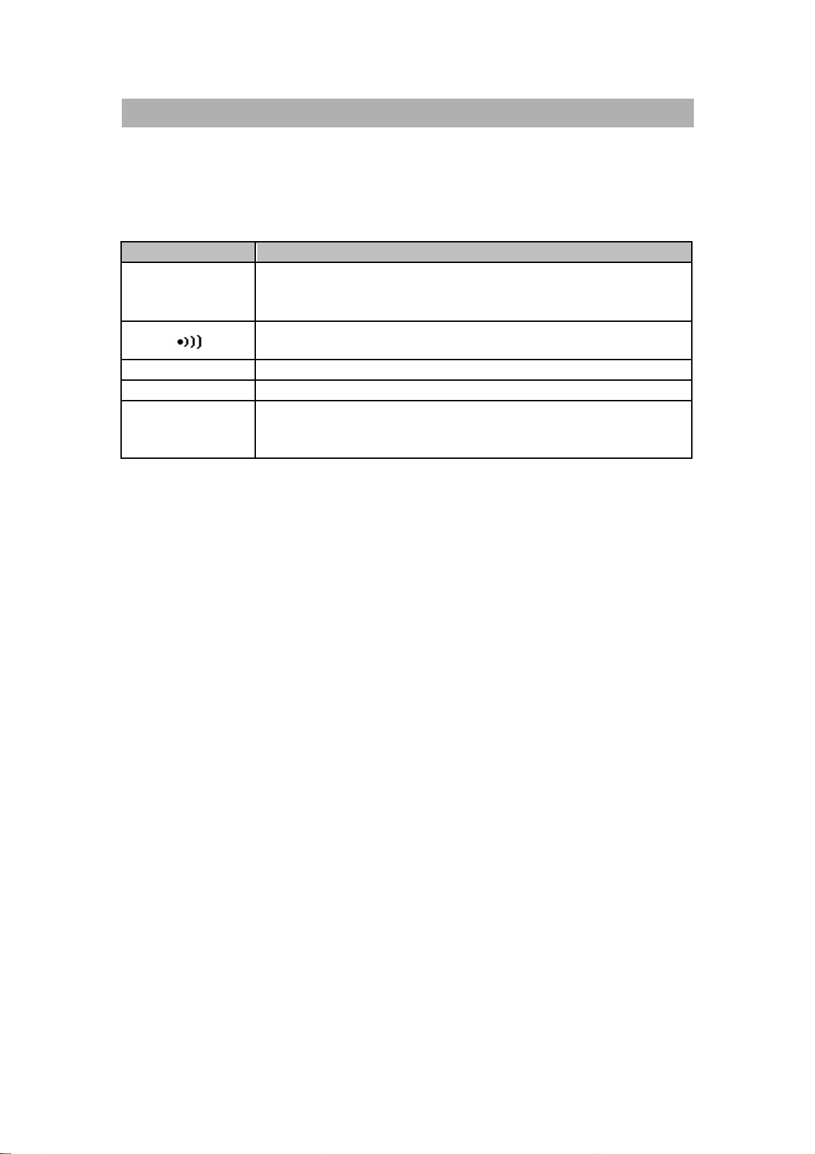
basic problems:
Malfunction Identification
No LCD indication as
power ON
Check whether the power button has been
locked completely.
Check batteryor replace battery.
No beeper tone Checksetup mode whether the beeper has been
want
Pushbuttons failure Check whether themeter is under remote
control.
Turn OFF and then turn ON the meter again.
Check the setup mode whether “Lbut” of lock
buttons has been set “on”.
Failed on Remote control The optical side of cable connected to meter, the
text side of cover should be up.
Check the baud rate, parity, Data bit,Stop bit
(default is 9600, n, 8, 1)
Driver install for USB- RS232.
Page 53

-48-
Battery replacement
WARNING
Remove all test leads andexternal adaptor before
opening the case.
The meter is powered by9 V battery, be sure to usedspecified battery. To
ensure thespecificationspecified, it is suggested to replace battery
immediatelyas the sign of is displayed and flashing.Following
procedures for battery replacement:
1. Remove alligator clip lead and turn offthe meter.
2. Release the screw on the batterycover.
3. Slide pull down the batterycover.
4. Then take up the cover.
5. Replace the specified battery.
6. Reverse the procedure of opening cover to close the bottom cover.
Figure- 26 Battery Replacement
Page 54

-49-
Cleaning
WARNING
To avoid electrical shock or damage to the
meter,do not get water inside the case.
To clean the instrument, use a softcloth dampened in a solution ofmild
detergent and water. Do not spray cleaner directlyonto the instrument,since it
mayleak into the cabinetand cause damage. Do not use chemicals
containing benzine, benzene, toluene, xylene, acetone or similarsolvents to
clean the instrument.After cleaning,makesure the instrumentis dried
completelybefore using.
Page 55

-50-
□Environmental Condition
This Tweeze rs is for Indoor use /Altitude up to 2000m.
Operation temperature: 0 C~40 C (32F~104F), R.H. 80%.
Storage Temperature: -20C to 60C (-4F~140F)
WARNING!
To avoid electrical shock, never use wet Tweezers for your instruments.
Page 56

-51-
Service Information
Warranty Service: Please return the product in the original packaging with proof of purchase to
the addressbelow. Clearly state in writing the performanceproblemand return any leads, probes,
connectorsand accessories that you are using with the device.
Non-WarrantyService: Return the product in the original packaging to the addressbelow.
Clearly state in writing the performance problem and return any leads, probes, connectors and
accessories that you are using with the device. Customersnot on open account must include
paymentin the form of a moneyorder or credit card.For the most current repair charges please
visit www.bkprecision.com and click on “service/repair”.
Returnall merchandise to B&K Precision Corp. with pre-paid shipping. The flat-rate repair charge
for Non-Warranty Service doesnotinclude return shipping. Return shipping to locations in North
Americanisincluded for Warranty Service. For overnight shipments and non-North American
shipping fees please contact B&K Precision Corp.
B&K Precision Corp.
22820 Savi Ranch Parkway
Yorba Linda, CA 92887
www.bkprecision.com
714-921-9095
Include with the returned instrument your complete returnshipping address, contact
name, phone numberand description of problem.
Page 57

Page 58

Printed in Taiwan
22820 Savi Ranch Parkway
2007 B&K Precision Corp.
Yorba Linda, CA 92887
USA
TEL: 714-921-9095
FAX:714-921-6422
www.bkprecision.com
 Loading...