

Page 1

5490C Series
5 ½ and 6 ½ Digit Multimeters
Models: 5492C/5492CGPIB, 5493C/5493CGPIB
USER MANUAL
Page 2

Safety Summary
The following safety precautions apply to both operating and maintenance personnel and must
be followed during all phases of operation, service, and repair of this instrument.
Before applying power to this instrument:
Read and understand the safety and operational information in this manual.
Apply all the listed safety precautions.
Verify that the voltage selector at the line power cord input is set to the correct line
voltage. Operating the instrument at an incorrect line voltage will void the warranty.
Make all connections to the instrument before applying power.
Do not operate the instrument in ways not specified by this manual or by B&K Precision.
Failure to comply with these precautions or with warnings elsewhere in this manual violates the
safety standards of design, manufacture, and intended use of the instrument. B&K Precision
assumes no liability for a customer’s failure to comply with these requirements.
Category rating
The IEC 61010 standard defines safety category ratings that specify the amount of electrical
energy available and the voltage impulses that may occur on electrical conductors associated
with these category ratings. The category rating is a Roman numeral of I, II, III, or IV. This rating
is also accompanied by a maximum voltage of the circuit to be tested, which defines the voltage
impulses expected and required insulation clearances. These categories are:
Category I (CAT I): Measurement instruments whose measurement inputs are not intended to
be connected to the mains supply. The voltages in the environment are typically derived from a
limited-energy transformer or a battery.
Category II (CAT II): Measurement instruments whose measurement inputs are meant to be
connected to the mains supply at a standard wall outlet or similar sources. Example
measurement environments are portable tools and household appliances.
Category III (CAT III): Measurement instruments whose measurement inputs are meant to be
connected to the mains installation of a building. Examples are measurements inside a
building's circuit breaker panel or the wiring of permanently-installed motors.
Category IV (CAT IV): Measurement instruments whose measurement inputs are meant to be
connected to the primary power entering a building or other outdoor wiring.
ii
Page 3

Do not use this instrument in an electrical environment with a higher category rating than what
is specified in this manual for this instrument.
You must ensure that each accessory you use with this instrument has a category rating equal to
or higher than the instrument's category rating to maintain the instrument's category rating.
Failure to do so will lower the category rating of the measuring system.
Electrical Power
This instrument is intended to be powered from a CATEGORY II mains power environment. The
mains power should be 120 V RMS or 240 V RMS. Use only the power cord supplied with the
instrument and ensure it is appropriate for your country of use.
Ground the Instrument
To minimize shock hazard, the instrument chassis and cabinet must be connected to an
electrical safety ground. This instrument is grounded through the ground conductor of the
supplied, three-conductor AC line power cable. The power cable must be plugged into an
approved three-conductor electrical outlet. The power jack and mating plug of the power cable
meet IEC safety standards.
Do not alter or defeat the ground connection. Without the safety ground connection, all
accessible conductive parts (including control knobs) may provide an electric shock. Failure to
use a properly-grounded approved outlet and the recommended three-conductor AC line power
cable may result in injury or death.
Unless otherwise stated, a ground connection on the instrument's front or rear panel is for a
reference of potential only and is not to be used as a safety ground.
Do not operate in an explosive or flammable atmosphere
Do not operate the instrument in the presence of flammable gases or vapors, fumes, or finelydivided particulates.
The instrument is designed to be used in office-type indoor environments. Do not operate the
instrument
In the presence of noxious, corrosive, or flammable fumes, gases, vapors, chemicals, or
iii
Page 4

finely-divided particulates.
In relative humidity conditions outside the instrument's specifications.
In environments where there is a danger of any liquid being spilled on the instrument or
where any liquid can condense on the instrument.
In air temperatures exceeding the specified operating temperatures.
In atmospheric pressures outside the specified altitude limits or where the surrounding
gas is not air.
In environments with restricted cooling airflow, even if the air temperatures are within
specifications.
In direct sunlight.
This instrument is intended to be used in an indoor pollution degree 2 environment. The
operating temperature range is 0 °C to 40 °C and the operating humidity range is up to 80%
relative humidity with no condensation allowed.
Measurements made by this instrument may be outside specifications if the instrument is used
in non-office-type environments. Such environments may include rapid temperature or
humidity changes, sunlight, vibration and/or mechanical shocks, acoustic noise, electrical noise,
strong electric fields, or strong magnetic fields.
Do not operate instrument if damaged
If the instrument is damaged, appears to be damaged, or if any liquid, chemical, or other
material gets on or inside the instrument, remove the instrument's power cord, remove the
instrument from service, label it as not to be operated, and return the instrument to B&K
Precision for repair. Notify B&K Precision of the nature of any contamination of the instrument.
Clean the instrument only as instructed
Do not clean the instrument, its switches, or its terminals with contact cleaners, abrasives,
lubricants, solvents, acids/bases, or other such chemicals. Clean the instrument only with a
clean dry lint-free cloth or as instructed in this manual.
Not for critical applications
This instrument is not authorized for use in contact with the human body or for use as a
component in a life-support device or system.
iv
Page 5

Do not touch live circuits
Instrument covers must not be removed by operating personnel. Component replacement and
internal adjustments must be made by qualified service-trained maintenance personnel who
are aware of the hazards involved when the instrument's covers and shields are removed.
Under certain conditions, even with the power cord removed, dangerous voltages may exist
when the covers are removed. To avoid injuries, always disconnect the power cord from the
instrument, disconnect all other connections (for example, test leads, computer interface
cables, etc.), discharge all circuits, and verify there are no hazardous voltages present on any
conductors by measurements with a properly-operating voltage-sensing device before touching
any internal parts. Verify the voltage-sensing device is working properly before and after making
the measurements by testing with known-operating voltage sources and test for both DC and AC
voltages. Do not attempt any service or adjustment unless another person capable of rendering
first aid and resuscitation is present.
Do not insert any object into an instrument's ventilation openings or other openings.
Hazardous voltages may be present in unexpected locations in circuitry being tested when a
fault condition in the circuit exists.
Fuse replacement
Fuse replacement must be done by qualified service-trained maintenance personnel who are
aware of the instrument's fuse requirements and safe replacement procedures. Disconnect the
instrument from the power line before replacing fuses. Replace fuses only with new fuses of the
fuse types, voltage ratings, and current ratings specified in this manual or on the back of the
instrument. Failure to do so may damage the instrument, lead to a safety hazard, or cause a fire.
Failure to use the specified fuses will void the warranty.
Servicing
Do not substitute parts that are not approved by B&K Precision or modify this instrument.
Return the instrument to B&K Precision for service and repair to ensure that safety and
performance features are maintained.
v
Page 6

This product is subject to Directive 2002/96/EC of the European
Parliament and the Council of the European Union on waste
electrical and electronic equipment (WEEE), and in jurisdictions
adopting that Directive, is marked as being put on the market after
August 13, 2005, and should not be disposed of as unsorted
municipal waste. Please utilize your local WEEE collection facilities
in the disposition of this product and otherwise observe all
applicable requirements.
Cooling fans
This instrument contains one or more cooling fans. For continued safe operation of the
instrument, the air inlet and exhaust openings for these fans must not be blocked nor must
accumulated dust or other debris be allowed to reduce airflow. Maintain at least 25 mm
clearance around the sides of the instrument that contain air inlet and exhaust ports. If
mounted in a rack, position power devices in the rack above the instrument to minimize
instrument heating while rack mounted. Do not continue to operate the instrument if you
cannot verify the fan is operating (note some fans may have intermittent duty cycles). Do not
insert any object into the fan's inlet or outlet.
For continued safe use of the instrument
Do not place heavy objects on the instrument.
Do not obstruct cooling airflow to the instrument.
Do not place a hot soldering iron on the instrument.
Do not pull the instrument with the power cord, connected probe, or connected test
lead.
Do not move the instrument when a probe is connected to a circuit being tested
Compliance Statements
Disposal of Old Electrical & Electronic Equipment (Applicable in the European
Union and other European countries with separate collection systems)
vi
Page 7

CE Declaration of Conformity
This instrument meets the requirements of 2014/35/EU Low Voltage Directive and 2014/30/EU
Electromagnetic Compatibility Directive with the following standards.
Low Voltage Directive
- EN 61010-1: 2010
EMC Directive
- EN 61326-1: 2013
vii
Page 8

Refer to the user manual for warning information
to avoid hazard or personal injury and prevent
damage to instrument.
Electric Shock hazard
This is the AC mains connect/disconnect
mechanical power switch.
On (Power). This is the In position of the power
switch when instrument is ON.
Off (Power). This is the Out position of the power
switch when instrument is OFF.
Power standby. The unit is not completely
disconnected from the AC mains in off state.
Alternating current (line)
Chassis (earth ground) symbol
Ground terminal
Protective earth ground
CAUTION indicates a hazardous situation which, if
not avoided, will result in minor or moderate injury
WARNING indicates a hazardous situation which, if
not avoided, could result in death or serious injury
DANGER indicates a hazardous situation which, if
not avoided, will result in death or serious injury.
Safety Symbols
viii
Page 9

Contents
Safety Summary ....................................................................................................................................................... ii
Compliance Statements .......................................................................................................................................... vi
CE Declaration of Conformity ................................................................................................................................ vii
Safety Symbols ...................................................................................................................................................... viii
1 General Information ...................................................................................................................................3
1.1 Operating Environment ..................................................................................................................................... 3
1.2 Package Contents ............................................................................................................................................... 3
1.3 Product Dimensions ........................................................................................................................................... 4
1.4 Front Panel Overview ........................................................................................................................................ 4
1.5 Rear Panel Overview .......................................................................................................................................... 5
Getting Started ...........................................................................................................................................6
2.1 Input Power and Fuse Requirements................................................................................................................. 6
2.2 Check and/or Change Fuse ................................................................................................................................ 7
2.3 Carrying Handle Adjustment ............................................................................................................................. 8
Front Panel Operation .................................................................................................................................9
3.1 Front Panel Menu Reference ............................................................................................................................. 9
3.2 Display ............................................................................................................................................................. 11
3.2.1 Change Display Mode .......................................................................................................................... 11
3.2.2 Display Label Text ................................................................................................................................ 12
3.2.3 Digit Mask ............................................................................................................................................ 13
3.2.4 Probe Hold Function ............................................................................................................................ 13
3.2.5 Screen Capture and File Transfer ......................................................................................................... 14
3.3 Basic Measurements ........................................................................................................................................ 14
3.3.1 DC Voltage ........................................................................................................................................... 14
3.3.2 DCV Ratio ............................................................................................................................................. 16
3.3.3 AC Voltage............................................................................................................................................ 16
3.3.4 DC Current ........................................................................................................................................... 18
3.3.5 AC Current ........................................................................................................................................... 19
3.3.6 Resistance 2W (2-wire) ........................................................................................................................ 21
3.3.7 Resistance 4W (4-wire) ........................................................................................................................ 22
3.3.8 Capacitance Measurement .................................................................................................................. 23
3.3.9 Diode ................................................................................................................................................... 24
3.3.10 Continuity .......................................................................................................................................... 25
3.3.11 Temperature test ............................................................................................................................... 26
3.3.12 Frequency measurement ................................................................................................................... 27
Secondary Measurement .......................................................................................................................... 29
Math Functions......................................................................................................................................... 29
Page 10

5.1 Null Operation ................................................................................................................................................. 29
5.2 Statistics ........................................................................................................................................................... 29
5.3 Limit ................................................................................................................................................................. 30
5.4 dB Calculation .................................................................................................................................................. 30
5.5 dBm Calculation ............................................................................................................................................... 30
5.6 mX+b ................................................................................................................................................................ 30
5.7 Percent ............................................................................................................................................................. 30
Save / Recall ............................................................................................................................................. 31
6.1 Save Readings .................................................................................................................................................. 31
6.2 Save Settings .................................................................................................................................................... 31
6.3 Recall Settings .................................................................................................................................................. 31
6.4 Power On ......................................................................................................................................................... 32
System Settings ........................................................................................................................................ 33
7.1 Set the language .............................................................................................................................................. 33
7.2 Setting the date/time ...................................................................................................................................... 33
7.3 Setting the buzzer and brightness ................................................................................................................... 33
7.4 Setting the format of the digital display .......................................................................................................... 33
Interface ................................................................................................................................................... 34
8.1 RS232 interface ................................................................................................................................................ 34
8.1.1 RS232 Interface Operation .................................................................................................................. 34
8.2 USB Interface ................................................................................................................................................... 37
8.2.1 USB Device ........................................................................................................................................... 37
8.2.2 USB Host .............................................................................................................................................. 37
8.3 LAN Interface ................................................................................................................................................... 37
8.4 GPIB Interface .................................................................................................................................................. 38
8.4.1 GPIB Bus .............................................................................................................................................. 38
8.4.2 Setting the GPIB Address ..................................................................................................................... 40
8.4.3 General Bus Commands ...................................................................................................................... 40
8.4.4 Setting through the interface .............................................................................................................. 40
Specifications - 5492C / 5492CGPIB ............................................................................................................ 41
Specifications - 5493C / 5493CGPIB .......................................................................................................... 43
10.1 Supplementary specifications – 5493C / 5493CGPIB .................................................................................... 46
Service Information ................................................................................................................................. 47
2
Page 11

1 General Information
The 5490C Series 5 ½ and 6 ½-digit benchtop multimeters offer a broad measurement range with
speeds up to 1000 readings per second, and a basic DC Voltage accuracy up to 35 ppm delivering
measurement results quickly and accurately.
5492C/5493C has broad measurement ranges:
DC voltage from 0.1 μV to 1000 V
AC voltage from 0.1 μV to 750 VAC, peak value of 1000 V
DC current from 10 nA to 10 A
AC current from 10 nA to 10 A
Resistance measurement from 0.01 mΩ to 120 MΩ
Capacitance from 0.1 pF to 10 mF
Frequency from 2.2 Hz to 1 MHz
Some additional capabilities:
Full range of functions: In addition to those listed above, 5492C/5493C functions include period,
dB, dBm, continuity, DC V ratio, diode testing, arithmetical operation (mX+b), and percentage
calculation.
Programming languages and remote control interfaces: This instrument supports SCPI
commands. The remote control interface ports include USB Device, RS232, LAN, and optional
GPIB interface (Model 5492CGPIB/5493CGPIB)
Readings and instrument settings: Up to 10,000 readings can be stored in local mode.
Completed calibration: The unit can be calibrated through a remote control interface.
1.1 Operating Environment
Power supply: 110V/220V ±10%
Line frequency: 50Hz / 60Hz ±5%
Power consumption: ≤ 30 VA
Operating temperature: 0 to 40
Humidity: ≤ 90% RH
1.2 Package Contents
5492C/5493C was carefully inspected mechanically and electrically before shipment. After unpacking
all items from the shipping carton, please check for any obvious signs of physical damage that may
have occurred during transportation. Report any damage to the shipping agent immediately. Save the
original packing carton for possible future shipments. The following items are included with every
5490C Series model:
1 x Model 5492C/5492CGPIB, 5493C/5493CGPIB Digital Multimeter
1 x Test leads (Model TL37)
3
Page 12
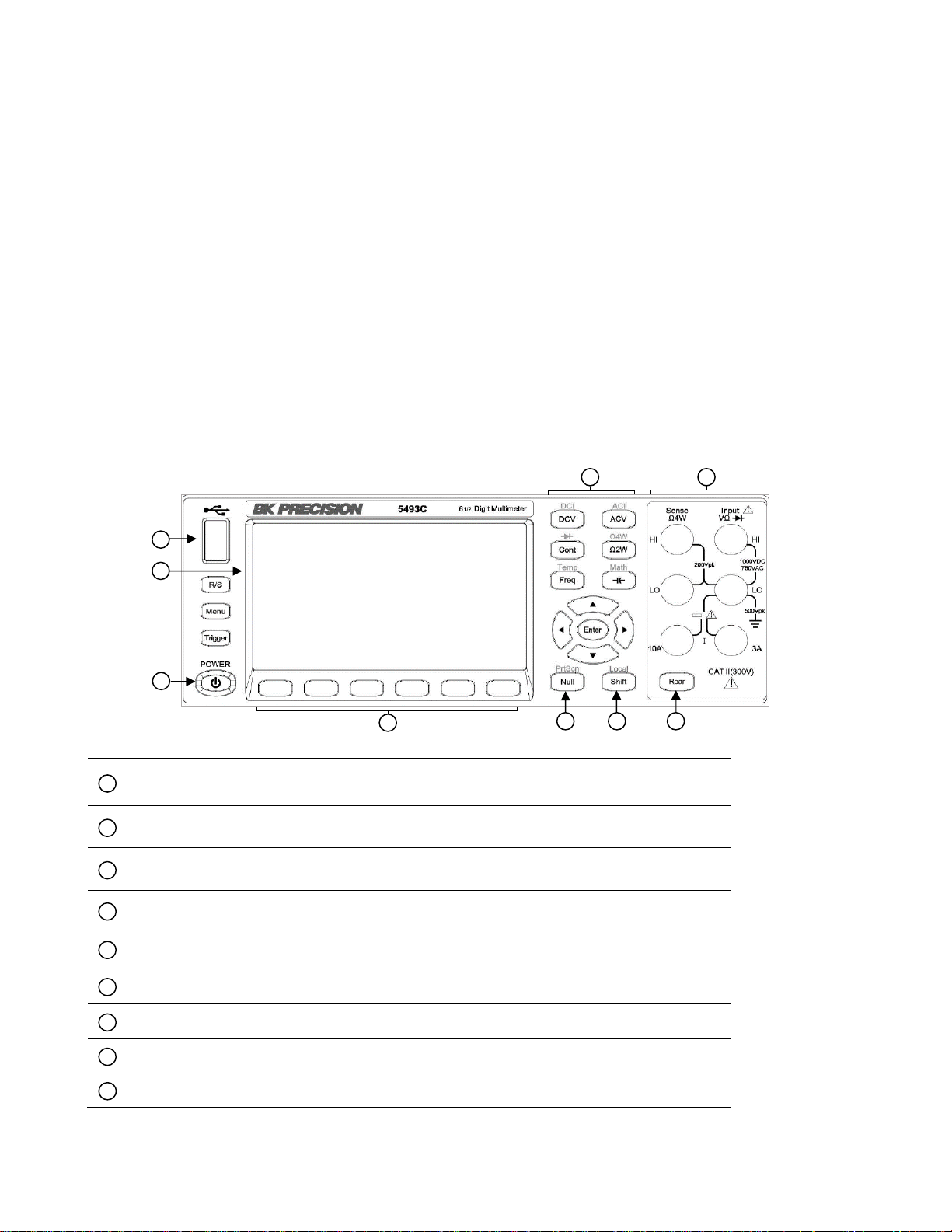
USB host port
4.3-inch LCD
Main function keys
Input terminals
Power standby button
Softkeys
Null/Screenshot key
Shift/Local key
Rear panel input button (on 6 ½-digit models only)
1 2 3
4
5 6 7
8
9
1 2 3
4 5 6
7 8 9
1 x USB interface connection cable
1 x AC power cord
1 x T500 mAL fuse
1 x Test report
1 x Certificate of Calibration
Verify that you have received all the items above when you get the multimeter. If anything is missing,
please contact B&K Precision.
1.3 Product Dimensions
Dimensions (W×H×D): 225mm×100mm×355mm
Net weight: Approximately 5.51 lbs (2.5 kg)
1.4 Front Panel Overview
Front Panel Description
4
Page 13
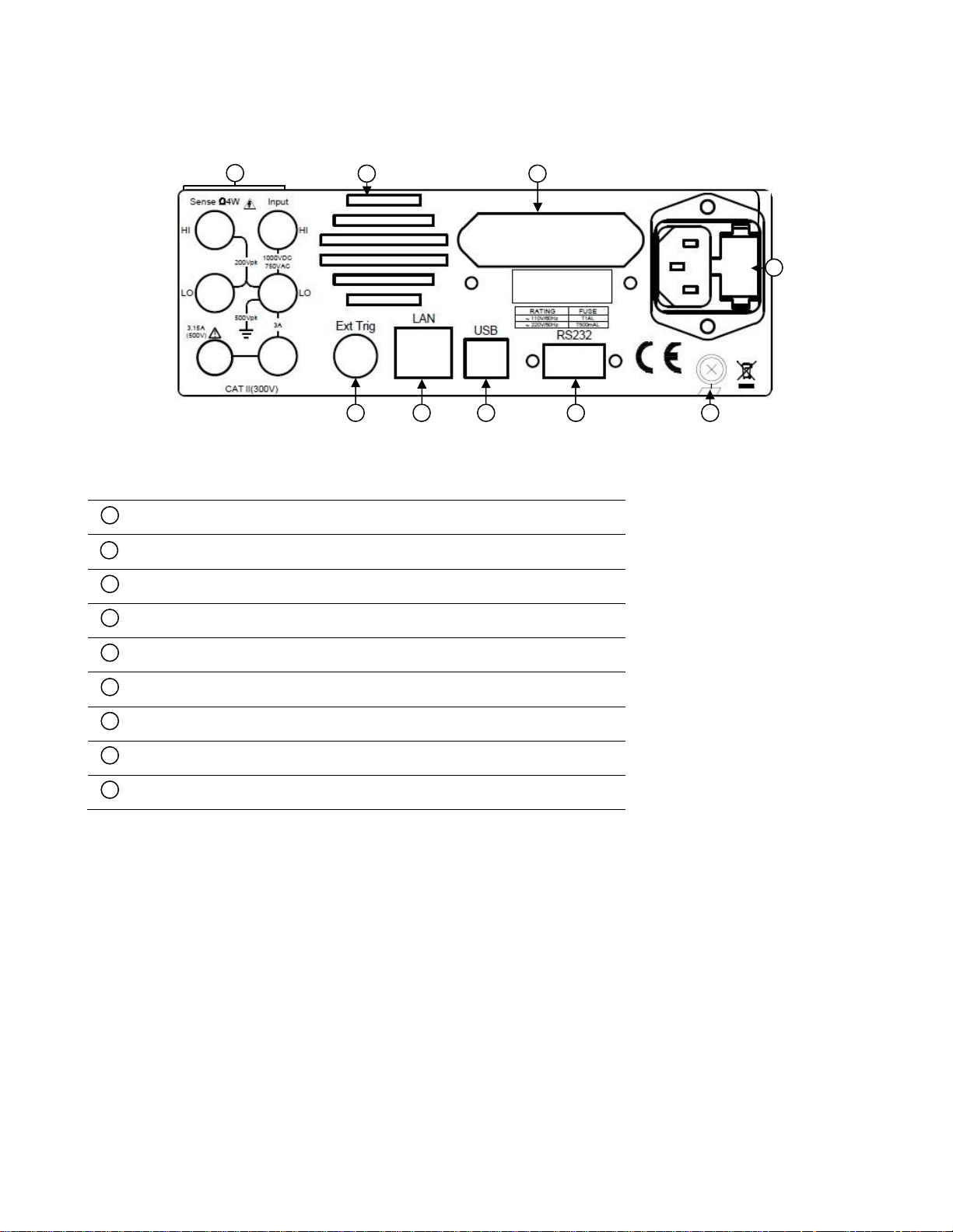
Rear input terminals (6 ½-digit models only)
Cooling fan
GPIB interface (5492CGPIB/5493CGPIB models only)
AC power input receptacle & fuse box
External Trigger BNC connector
LAN interface
USB interface
RS232 interface
Chassis ground
1 3 4 5 6
7 8 9 1 2 3 2 4 5 6 7 8 9
1.5 Rear Panel Overview
Rear Panel Description
5
Page 14
RATING
FUSE
~ 110V/60Hz
T1 AL
~ 220 V/50Hz
T500mAL
The included AC power cord is safety certified for this
instrument operating in rated range. To change a
cable or add an extension cable, be sure that it can
meet the required power ratings for this instrument.
Any misuse with wrong or unsafe cables will void the
warranty.
SHOCK HAZARD:
The power cord provides a chassis ground through a
third conductor. Verify that your power outlet is of the
three-conductor type with the correct pin connected
to earth ground.
Getting Started
Before connecting and powering up the instrument, please review the instructions in this chapter.
2.1 Input Power and Fuse Requirements
The 5490C Series digital multimeters can operate on 110 V or 220 V with +/-10% tolerance at 60 Hz or
50 Hz. Before powering the instrument, please check for the correct power input setup that
corresponds to the line voltage to be used for operation. Note the label on the rear panel of the
instrument as shown below:
Table 2.1 – Fuse Table
Before connecting to an AC outlet or external power source, verify that the AC power cord, including
the extension line, is compatible with the rated voltage/current and that there is sufficient circuit
capacity for the power source. Once verified, connect the cable firmly.
6
Page 15

For safety, no power should be applied to the
instrument while changing line voltage operation.
Disconnect all cables connected to the instrument
before proceeding.
Any disassembling of the case or changing the fuse
should be performed by an authorized service
technician.
2.2 Check and/or Change Fuse
Check and/or Change Fuse
- Locate the fuse box next to the AC input connector in the rear panel
- Remove the fuse box as shown in Figure 2.2 – AC Input Fuse Removal below
- Check and replace fuse if necessary
Figure 2.2 – AC Input Fuse Removal
7
Page 16

Be sure the handle is locked in position and avoid
twisting movements while transporting as the handle
can damage and drop the instrument.
To remove the fuse holder and access the fuse, use a flat head screw driver and
turn counter-clockwise. Similarly, push the fuse holder inward and turn clockwise
to replace the fuse.
Bench Operation
There is a second fuse with a fuse holder located in the rear panel of the multimeter. This is an
overcurrent protection fuse for the low current measurement input. It is a 5 x 20 mm 250 V, 3.15 A
slow blow 50T glass fuse.
A third fuse is located inside the instrument which protects the 10 A input terminal if the input current
exceeds the maximum rating. It is a 6 x 32 mm 250 V, 12 A fast blow fuse.
2.3 Carrying Handle Adjustment
To adjust the position, grasp the handle on both sides of the instrument at the pivot point and rotate
the handle to the desired position. Be sure the handle locks in its new position.
Handle transport position
8
Page 17

Key
Usage
DCV(DCI)
To configure the DC voltage measurement, including DC ratio measurement
Range: 100mV, 1V, 10V, 100V, 1000V
Range is set to Auto by default
NPLC: {0.02, 0.2, 1, 10, 100} Default: 10 PLC
Auto zero setting: OFF or ON (default: ON)
Input impedance: 10M or HighZ (>1G)
DC ratio: OFF (default) or ON
Shift + DCV(DCI)
To configure the DC current measurement
Range: 3 A terminal (100uA, 1mA, 10mA, 100mA, 1A, 3A) auto range (default)
10A port 10A range
NPLC: {0.02, 0.2, 1, 10, 100} Default: 10 PLC
Range is set to Auto by default
NPLC: {0.02, 0.2, 1, 10, 100} Default: 10 PLC
Auto zero setting: OFF or ON (default: ON)
ACV(ACI)
To configure the ACV AC voltage
Range: Auto (default), 100mV, 1V, 10V, 100V, 750V
Filter: 3Hz (slow speed)
20Hz (medium, slow speed)
200Hz (fast, medium and slow speed)
Default: 20Hz filter, medium speed
Shift + ACV(ACI)
To configure the ACV AC current measurement
Test terminal: 3 A 10 A
Range: 3 A terminal (100uA, 1mA, 10mA, 100mA, 1A, 3A) auto range (default)10
A port 10 A range
Filter: 3Hz (slow speed)
20Hz (medium, slow speed)
200Hz (fast, medium and slow speed)
Default: 20Hz filter, medium speed
Ω2W(Ω4W)
To configure the two-wire resistance test
Range: Auto Range (default) {10Ω, 100Ω, 1kΩ, 10kΩ, 100kΩ, 1MΩ, 10MΩ,
100MΩ}
NPLC: {0.02, 0.2, 1, 10, 100} Default: 10 PLC
Auto zero setting: OFF or ON (default: ON)
Shift
+Ω2W(Ω4W)
To configure the four-wire resistance test
Range: Auto Range (default) {10Ω, 100Ω, 1kΩ, 10kΩ, 100kΩ, 1MΩ, 10MΩ,
100MΩ}
Front Panel Operation
This chapter covers available function settings and how to make basic measurements.
3.1 Front Panel Menu Reference
9
Page 18

NPLC: {0.02, 0.2, 1, 10, 100} Default: 10 PLC
Freq (Temp)
To configure the frequency and period measurements
Filter: 3 Hz, 20 Hz, 200 Hz
Gating time: 10ms, 100ms (default), 1s
Shift + Freq
(Temp)
To configure the temperature test
Probe type: two-wire test (default) or four-wire test
R0: resistance at 0 °C, default: 100 Ω
NPLC: {1, 10, 100} Default: 10 PLC
Unit: °C, °F, K,
Cont (diode)
Conduction (continuous) configuration
Test range: 1 kΩ
Test current: 1 mA
Buzzer: ON (default) or OFF
Door threshold: default 10 Ω, can be set separately
Shift + Cont
(diode)
Diode configuration
Test voltage range: 0~5V
Test current: 1 mA
Buzzer: ON (default) or OFF
CAP(MATH)
Capacitance measurement configuration
Range: Auto (default) {1nF, 10F, 100nF, 1uF, 10uF, 100uF, 1mF, 10mF}
Shift+
CAP(MATH)
Math zero calculation (NULL), you can set parameters
dB/dBm operation
smoothing
scal: Mx+b, Percent
Statistics, Limit
NULL (PrtScn)
Mathematical zeroing calculation, the calculated value is the current measured
data
Shift+NULL
(PrtScn)
Print the picture and save the current display interface
R/S
Run or Stop
Trigger
Single trigger
Menu
Menu Settings
Display: display settings
Acquire: trigger option
Utility: general function
10
Page 19

3.2 Display
The multimeters display can be set to number, bar meter, trend chart, or histogram. By default, the
meter will be set to number display.
3.2.1 Change Display Mode
To change the display mode, press Menu → Display → Display to access the display options. Use the
softkey to select the desired display mode.
Bar Meter
The bar meter displays live measurements on a horizontal bar graph. Press ‘Auto Scale’ to
automatically adjust the upper and lower limits or set the limits manually using. Use the softkeys and
directional keypad to adjust the Low/High values.
The bar meter display mode can also enabled with Limit mode. The upper and lower limits are
displayed on the bar meter in red.
11
Page 20

Trend Chart
The trend chart plots data as a trend line over time. The mode can be changed to display recent data
where the time in seconds before present can be adjusted. Press the ‘Scale’ softkey to then select
‘Manual’ and use the directional keypad to adjust top/bottom boundaries.
Histogram
The histogram display mode groups data into bins represented graphically in vertical bars. By default
the Bin count is set to Auto. The Bin count can be changed manually to 10, 20, 40, 100, 200, or 400.
When using manual Bins, the high/low bounds can be adjusted using the directional keypad. When
statistics are displayed in histogram mode, the dark blue line in the middle represents the average,
and the outside blue lines represent on standard deviation from the average.
3.2.2 Display Label Text
Label text can be added to the measurement display. To set label text and display a label, press
Menu → Display → Label Text and use the on-screen keyboard to enter text. Press ‘Done’ then press
the softkey for ‘Label OFF/ON’ to display the text.
12
Page 21

3.2.3 Digit Mask
The number of display digits can be changed manually. By default, the digit mask will change
automatically based on other function settings and PLC settings.
To change the digit mask press Menu → Display → Digit Mask.
3.2.4 Probe Hold Function
The probe hold function records and displays up to 8 stable measurements adding them to an on-
screen list. To enable this function, press Menu → Display → Probe Hold → Probe Hold OFF/ON. In the
probe hold settings, the beeper can be enabled to output an audible beep when a stable reading is
recorded and added to the list. Note: the screen capture function can be used to save the displayed
list of measurements as an image.
13
Page 22

Do not apply more than 1000 V peak to the input or it will
damage the instrument.
3.2.5 Screen Capture and File Transfer
Press then press to save a screen capture to the multimeters internal memory as a .png
file. Screen captures can be transferred from internal memory to a USB flash drive using the built-in
file management system. Press Menu → Utility → Manage Files to access stored files. Use the
directional keypad to highlight the file to be transferred then press Copy. Highlight the USB resource
then press Paste to save a copy of the file.
3.3 Basic Measurements
3.3.1 DC Voltage
Step 1: Connect the input terminals as shown below.
Step 2: Press the button on the front panel to enter the DCV measurement function.
14
Page 23

Step 3: Range selection.
Press Range and select the range. Auto range (Auto) can automatically select the appropriate range for
measurement based on the input signal. The auto range is adjusted upwards to 120% of the existing
range and down to 10% of the existing range.
Step 4: Set the integration time.
The setting of the integration time affects the measurement speed and measurement accuracy. The
longer the integration time, the higher the accuracy but the slower the measurement. 1PLC, 10PLC,
and 100PLC can inhibit noise. Selecting 100PLC can provide the best noise rejection, but at a slower
rate.
Step 5: Auto Zero.
Auto-zeroing results in more accurate measurements but requires more test time. With auto zero
enabled, the digital multimeter measures the offset once and subtracts the offset from all
subsequently measured parameters. This avoids the effect of the offset voltage on the input circuit of
the digital multimeter on the measurement accuracy. The DMM makes a new offset measurement
each time you change the function, range, or integration time. The default state is ON.
Step 6: Input Z internal resistance selection
Select the data input impedance. The input impedance can be automatic or 10MΩ. Automatic mode
selects high impedance (HighZ), which is appropriate for 100 mV, 1 V, 10 V ranges. The internal
resistance of the 100 V and 1000 V ranges is fixed at 10 MΩ.
Note: When attempting to measure a unipolar AC+DC signal in DCV mode, manual ranges should be
used for best accuracy.
15
Page 24

3.3.2 DCV Ratio
The DCV Ratio measurement function takes the ratio between two DC voltage measurements. The
ratio is calculated by dividing the input voltage (DCV1) by a reference voltage (DCV2), refer to Figure
3.2.2 – DCV Ratio below.
Step 1: Properly connect the input terminals as shown:
Figure 3.2.2 – DCV Ratio
Step 2: Turn on the DCV Ratio function. In DCV mode, enable DCV Ratio by pressing the softkey.
3.3.3 AC Voltage
This section describes how to configure the 5490C Series for AC voltage measurements. In order to get
the most accurate measurement, the corresponding RC time constant must be stable to 1/50 of the
input AC signal level.
Signals greater than 300 V (RMS) or 1 A (RMS) can cause self-heating of the signal conditioning
components. These errors are included in the instrument's specifications. Internal temperature
changes caused by self-heating may cause additional errors in other functions or ranges. Additional
errors typically disappear within a few minutes. Example: Consider a 100 VAC signal with a 5 VDC bias
voltage as an example, the 5 VDC bias voltage should be stable at 1/50 of 100 VAC or 2 VDC.
16
Page 25

Calculate the corresponding settling time using the RC time constant 0.22 s:
settling time = ln(bias/settled value)*0.22 s
settling time = ln(5 VDC / 2 VDC)*0.22 s
settling time = 0.20 s
The ACV function should be selected after the signal is connected to the digital multimeter's ACV
input or when the signal has been connected, enough extra delay should be given to stabilize the
signal. If the DC bias remains the same, a completely accurate subsequent measurement can be made
without additional stabilization delay.
Step 1: Configure the test leads as shown below.
Step 2: Press the button on the front panel to enter the ACV function interface.
Step 3: Range adjustment.
Press Range and select the range. Auto range (Auto) automatically selects the appropriate range for
measurement based on the input signal. The auto range is adjusted upwards to 110% of the existing
range and down to 10% of the existing range.
Step 4: AC Filter Selection.
The instrument offers three filter options consisting of 3Hz, 20Hz and 200Hz. The filter you choose
should be the highest filter which is less than the frequency of your test signal.
17
Page 26

Filter
Slow
Medium
Fast
3Hz
√ ﹣ ﹣
20Hz
√ √ ﹣
200Hz
√ √ √
For example, if the input signal is 300 Hz, the stable data can be obtained using the 200 Hz filter.
Step 5: Speed selection.
Each filter has a different test speed, choosing the right measurement speed based on the filter will
result in more accurate test results and/or faster test speeds.
3.3.4 DC Current
Step 1: Using either the 3 A or 10 A input terminal, configure the test leads as follows:
Use the 10 A terminal for current measurements greater than 3 A.
Step 2: Press on the front panel then press to select the DCI function and enter the DCI
function interface.
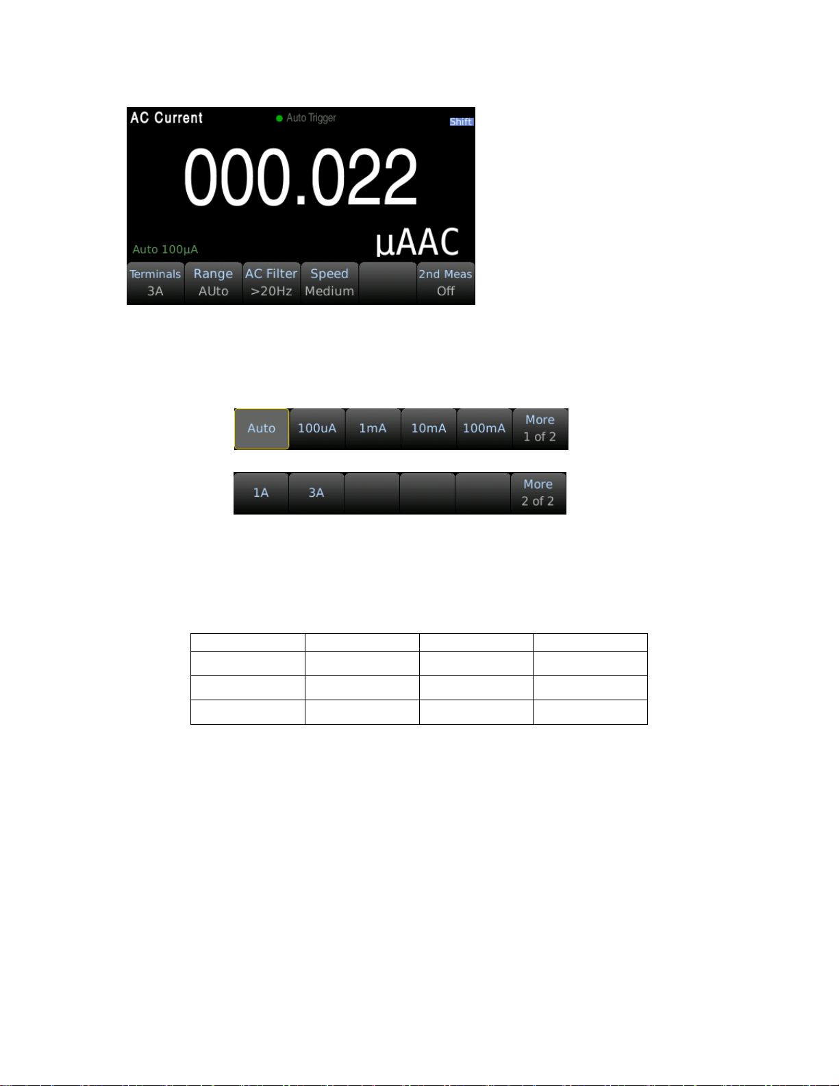
Step 3: Range adjustment.
Select the input terminal for the test signal. If you select 10 A input terminal, there is only 10 A range.
If you select 3 A input terminal: 100 uA, 1 mA, 10 mA, 100 mA, 1 A, 3 A, or Auto ranges are available.
Select the range using the softkeys:
Step 4: Set the integration time.
The setting of the integration time affects the measurement speed and measurement accuracy. The
longer the integration time, the higher the accuracy but the slower the measurement.
18
Page 27

PLC (power-line cycle) 1PLC, 10PLC, 100PLC can inhibit AC input noise. Selecting 100PLC can provide
the best noise rejection, but at a slower rate.
Step 5: Auto Zero.
Auto-zeroing results in more accurate measurements but requires more test time. With auto zero
enabled, the digital multimeter measures the offset once and subtracts the offset from all
subsequently measured parameters. This avoids the effect of the offset voltage on the input circuit of
the digital multimeter on the measurement accuracy. The DMM makes a new offset measurement
each time you change the function, range, or integration time. The default state is ON.
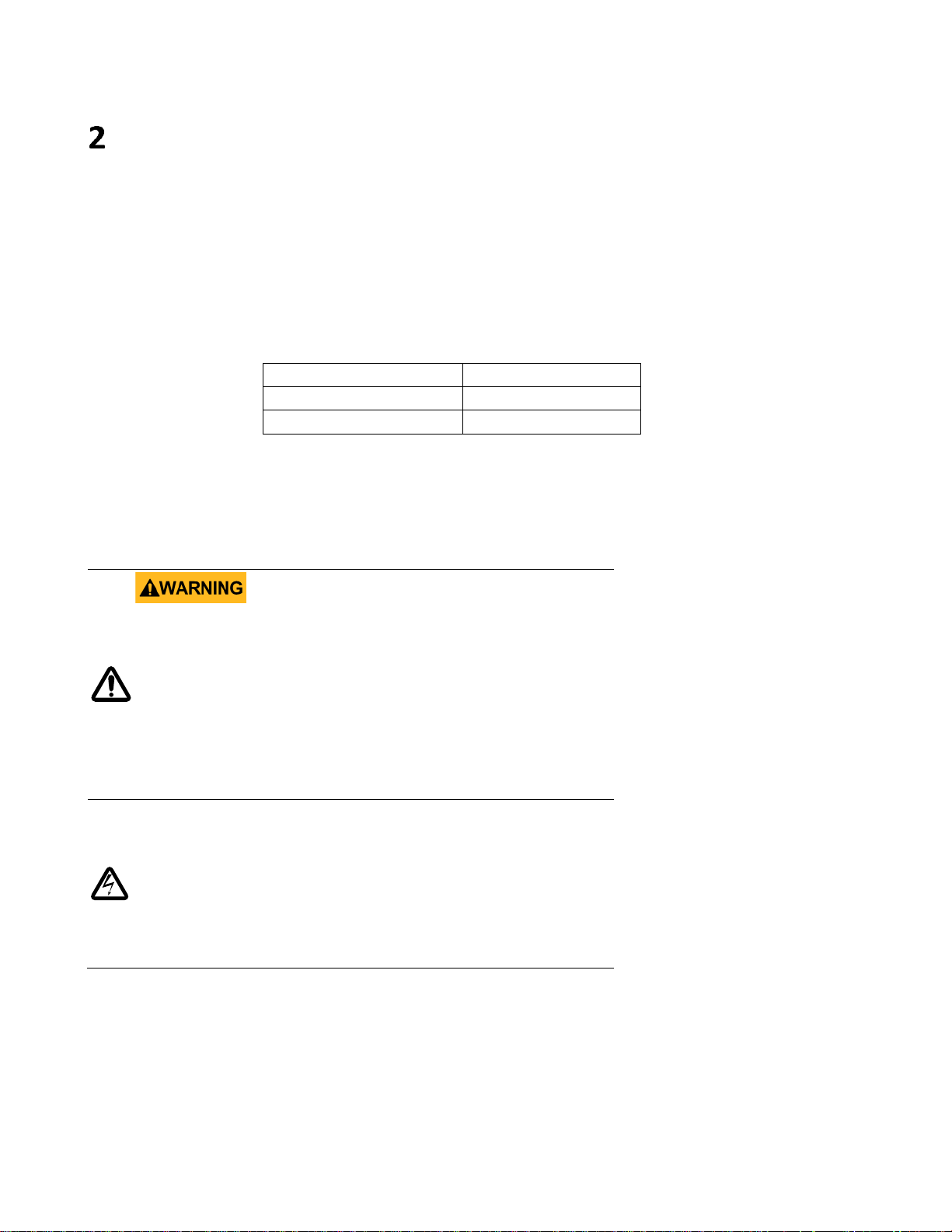
3.3.5 AC Current
Step 1: Using either the 3 A or 10 A input terminal, configure the test leads as follows:
Use the 10 A terminal for current measurements greater than 3 A.
Step 2: Press then press on the front panel to enter the ACI test interface.
19
Page 28
Filter
Slow
Medium
Fast
3Hz
√ ﹣ ﹣
20Hz
√ √ ﹣
200Hz
√ √ √
Step 3: Range adjustment
Use the softkeys to select the range. Auto range (Auto) can automatically select the appropriate range
for measurement based on the input signal. The auto range is adjusted upwards to 110% of the
existing range and down to 10% of the existing range.
Step 4: AC Filter Selection
The instrument offers three filter options of 3Hz, 20Hz and 200Hz. The filter you choose should be the
highest filter which is less than the frequency of your test signal. For example, if the input signal is
300Hz, the stable data can be obtained using the 200 Hz filter.
Step 5: Speed selection
Different filters have different test speeds, so choosing the right measurement speed based on the
filter can result in more accurate test results or faster test speeds.
20
Page 29

3.3.6 Resistance 2W (2-wire)
Step 1: Configure the test leads as follows:
Step 2: Press on the front panel to enter the two-wire resistance test interface.
Step 3: Select the range.
Press Range and select the range. Auto range (Auto) can automatically select the appropriate range for
measurement based on the input signal. The auto range is adjusted upwards to 110% of the existing
range and down to 10% of the existing range.
Step 4: Set the integration time.
The setting of the integration time affects the measurement speed and measurement accuracy. The
21
Page 30

longer the integration time, the higher the accuracy but the slower the measurement. PLC (power-line
cycle) 1PLC, 10PLC, 100PLC can inhibit AC input noise. Selecting 100PLC can provide the best noise
rejection, but at a slower rate.
Step 5: Auto Zero.
Auto-zeroing results in more accurate measurements but requires more test time. With auto zero
enabled, the digital multimeter measures the offset once and subtracts the offset from all
subsequently measured parameters. This avoids the effect of the offset voltage on the input circuit of
the digital multimeter on the measurement accuracy. The DMM makes a new offset measurement
each time you change the function, range, or integration time. The default state is ON.
3.3.7 Resistance 4W (4-wire)
Step 1: Configure the test leads as follows:
Step 2: Press then press on the front panel to enter the four-wire resistance test
interface.
22
Page 31

Step 3: Select the range.
Press Range and select the range. Auto range (Auto) can automatically select the appropriate range for
measurement based on the input signal. The auto range is adjusted upwards to 110% of the existing
range and down to 10% of the existing range.
Step 4: Set the integration time.
The setting of the integration time affects the measurement speed and measurement accuracy. The
longer the integration time, the higher the accuracy but the slower the measurement. PLC (power-line
cycle) 1PLC, 10PLC, 100PLC can inhibit AC input noise. Selecting 100PLC can provide the best noise
rejection, but at a slower rate.
3.3.8 Capacitance Measurement
Step 1: Configure the test leads as follows:
Step 2: Press on the front panel to enter the capacitance function interface.
23
Page 32

Step 3: Select the range.
Press Range and select the range. Auto range (Auto) can automatically select the appropriate range for
measurement based on the input signal. The auto range is adjusted upwards to 110% of the existing
range and down to 10% of the existing range.
3.3.9 Diode
This section describes how to configure the diode test from the front panel. The range and resolution
are fixed and the range is 10 VDC with 1 mA current source output.
Step 1: Configure the test leads as follows:
24
Page 33

Step 2: Press then press on the front panel to enter the diode test interface.
When converted to a 0.3V to 0.8V threshold, the instrument beeps (if a beep is enabled). A voltage of
0 to 5V is displayed on the front panel. When the measured break-over voltage is greater than 5V, the
front panel will display OPEN.
3.3.10 Continuity
This section describes how to configure the continuity test from the front panel.
Step 1: Configure the test leads as follows:
Step 2: Press on the front panel to open a menu that specifies whether the digital multimeter
will beep to indicate the continuity.
25
Page 34

≤ 10 Ω
Display the measured resistance and beeps (if the beeper is enabled).
10 Ω to 1.2 kΩ
Display measured resistance, no buzzer.
> 1.2 kΩ
Display OPEN (ON), no buzzer.
The continuity measurement behavior is as follows:
3.3.11 Temperature test
This section describes how to configure 2-wire and 4-wire temperature measurements from the front
panel. Temperature measurements require a temperature transducer probe.
Step 1: Configure the test leads as follows:
2-wire temperature 4-wire temperature
Step 2: Press then press on the front panel. The following menu will appear. Please note
that Auto Zero is only available for 2-wire measurements.
26
Page 35

Step 3: Press Probe to select the probe type. If you choose to use RTD, this menu will have a softkey to
specify the resistance of the RTD at 0 degrees Celsius (R0).
Step 4: Specify if you want to use Auto Zero. Auto-zeroing provides the most accurate measurements
but takes more time to perform a zero measurement.
With auto zero enabled, the digital multimeter internally measures the offset after each
measurement. This prevents the offset voltage on the digital multimeter (DMM) input circuit from
affecting the measurement accuracy. With auto zero disabled, the digital multimeter measures the
offset once and subtracts the offset from all subsequently measured parameters. The DMM makes a
new offset measurement each time you change the function, range, or integration time.
Step 5: Press Aperture and select the number of power line cycles (PLC) to measure. Normal mode
(line frequency noise) suppression is only available for 1, 10, and 100 PLCs. Selecting 100 PLCs
provides the best noise rejection and resolution, but the measurement is the slowest.
Step 6: Use the Unit softkey to display Celsius, Fahrenheit, or Kelvin.
3.3.12 Frequency measurement
This section describes how to configure frequency and period measurements from the front panel.
Step 1: Configure the test leads as shown below.
27
Page 36

Filter
Slow
Medium
Fast
3Hz
√ ﹣ ﹣
20Hz
√ √ ﹣
200Hz
√ √ √
Step 2: Press the button to enter the frequency measurement.
Use the Type softkey to select frequency or period measurement. Freq is the frequency measurement
and Period is the period measurement.
Step 3: Range adjustment
Press Range and select the range. Auto range (Auto) can automatically select the appropriate range for
measurement based on the input signal. The auto range is adjusted upwards to 110% of the existing
range and down to 10% of the existing range.
Step 4: AC Filter Selection.
The instrument offers three filter options of 3Hz, 20Hz and 200Hz. The filter you choose should be the
highest filter which is less than the frequency of your test signal. For example, if the input signal is
300Hz, the stable data can be obtained using the 200 Hz filter.
Step 5: Speed selection.
Different filters have different test speeds, so choosing the right measurement speed based on the
filter can result in more accurate test results or faster test speeds.
28
Page 37

Primary measurement function
Available secondary measurement function(s)
DCV
BeforeMath
DCI
BeforeMath
ACV
BeforeMath, Frequency
ACI
BeforeMath, Frequency
2W, 4W Resistance
Before math
Frequency
BeforeMath, AC Voltage, Period
Temperature
BeforeMath, Resistance
Capacitance
BeforeMath
Secondary Measurement
Several measurement functions support secondary measurements. Secondary display measurements
are only available when using Number or Bar Meter display modes only.
The BeforeMath secondary function displays raw measurement values when a Math function is
applied to the primary measurement.
Math Functions
Press then press to enter the math settings interface.
5.1 Null Operation
When using the Null function, the instrument takes the existing reading as a reference value, and the
subsequent readings subtract the reference value based on the actual input value.
Display reading = actual reading – reference value
Different measurement functions can set different reference values; once the reference value is set,
the reference values are the same for all ranges under the function.
Using the Null function does not increase the maximum allowed input signal for this range.
Set a user-defined null value using the softkeys and cursor navigation keys.
5.2 Statistics
Display the minimum (Min), maximum (Max), peak-to-peak (P-P), average (Average), standard
deviation (Std dev), and the total number of samples in the reading buffer.
The reading buffer can hold up to 10,000 data samples. When the reading buffer overflows, the oldest
data will be discarded. Press ‘Clear Readings’ using the softkey to reset the reading buffer.
29
Page 38

5.3 Limit
The limit test allows the user to perform a Pass/Fail test. By setting the upper and lower limit values,
the results will display the amount of Low and High failures. Use the softkeys to adjust Lower and
Upper limits. Set the limits by using the cursor navigation keys and button.
5.4 dB Calculation
The dB and dB math functions apply to DC V and ACV measurements only. This function allows
measurements to be scaled relative to a reference value.
Each dB measurement is the difference between the input signal and the stored reference value (both
converted to dBm): dB = reading in dBm – reference value in dBm
The relative value must be between -200 and +200 dBm (default is 0). You can measure this value by
pressing ‘Measure Ref Value’ or input a specified value using the softkeys.
5.5 dBm Calculation
The dBm function is a logarithmic expression that compares the power delivered to the reference
resistance, relative to 1 mW:
dBm = 10 x log10 (reading2 / reference resistance / 1 mW)
5.6 mX+b
The calculation of reading X on screen is performed as follows:
Where,
X is the normal display reading on the screen
m and b are the user-entered values
Y is the displayed result
5.7 Percent
If the percent calculation is selected, a reference value must be specified. The percentage calculation
is performed as follows:
Input is the measured reading
Reference is the user-entered constant
Percent is the displayed result
30
Page 39

Save / Recall
Measurement readings or instrument setting configurations can be saved into the instruments
nonvolatile memory or a USB flash drive connected to the front panel USB host port.
6.1 Save Readings
This function saves measurement data stored in the instrument buffer.
Press Menu → Utility → Save / Recall to access the Save / Recall settings then press Save Reading to
access the file management system. Use the softkeys and navigation keys to select a save location and
file type (.csv, .dat, or .txt). The folder named ‘files’ is the instruments nonvolatile memory. If a USB
flash drive is connected on the front panel, it will be displayed as ‘usb’. Folders and filenames can also
be modified. The save action can be set to ‘New’ to create a new file or ‘Replace’ to overwrite an
existing file. Press the ‘Save Readings’ softkey to complete the save process.
6.2 Save Settings
This function saves the current instrument state such as function selected and function settings.
Press Menu → Utility → Save / Recall to access the Save / Recall settings then press Save Settings to
access the file management system. Use the softkeys and navigation keys to select a save location and
file type (.sta or .prf). The folder named ‘files’ is the instruments nonvolatile memory. If a USB flash
drive is connected on the front panel, it will displayed as ‘usb’. Folders and filenames can also be
modified. The save action can be set to ‘New’ to create a new file or ‘Replace’ to overwrite an existing
file. Press the ‘Save Settings’ softkey to complete the save process.
6.3 Recall Settings
This function recalls instrument states stored in the instruments nonvolatile memory or on a USB flash
drive.
Press Menu → Utility → Save / Recall to access the Save / Recall settings then press Recall Settings to
access the file management system. Use the navigation keys to highlight an instrument state file which
have a .sta or .prf file extension. Press the ‘Recall’ softkey to complete the recall process.
31
Page 40

6.4 Power On
This function sets the instrument power on state which can be set to last, factory default, or a user
defined state. Press Menu → Utility → Save / Recall to access the Power On settings. By default the
power on state will be set to ‘Last’. To set a user defined power on state, an instrument state file saved
as .sta must first be saved to the instruments internal memory or on a USB flash drive. See section 6.2
Save Settings above for details on how to save an instrument state file. After a state file is created set
the ‘Power On’ settings to ‘User Defined’ using the softkeys. Select an instrument state file using the
‘User File’ softkey which will be enabled when the power on state is set to user defined as shown:
32
Page 41

System Settings
7.1 Set the language
Press Menu → Utility → System → User Settings → Language to switch the language.
The language can be set to English or Chinese.
7.2 Setting the date/time
Press Menu → Utility → System → Date Time to set the date and time.
Note: Setting the second is not supported using the front panel. The second can be set using the
command SYST: TIME <hour>, <minute>, <second> can be used.
7.3 Setting the buzzer and brightness
Press Menu → Utility → System → User Settings to enter the setup menu to set the sound and
brightness.
Beeper and Key Click are independent and do not affect each other.
In order to prevent the screen from being completely black, the minimum brightness is 20.
Tip: You can quickly adjust the brightness by using the then pressing up or down keys.
7.4 Setting the format of the digital display
Press Menu → Utility → System → User Settings → Number to set the format of the digit display.
In order to support the digital format commonly used in the U.S. and Europe, you can choose the
decimal point and separator type.
The decimal point can be set to '.' (Period) or ',' (Comma).
The separator can be a space, ',' or '.' (On), or no separator (None).
33
Page 42

Signal
Code
25 Pin Connector
Pin number
9 Pin Connector
Pin number
Request To Send
RTS
4
7
Clear To Send
CTS
5
8
Data Set Ready
DSR
6
6
Data Carrier Detect
DCD
8
1
Data Terminal Ready
DTR
20
4
Transmitted the data
TXD
2
3
Receive the data
RXD
3
2
Grounding
GND
7
5
Function
Code
Pin Connector Pin Number
Transmitted Data
TXD
3
Received Data
RXD
2
Signal Ground Common
GND
5
Interface
8.1 RS232 interface
RS232 standard, also called asynchronous serial communication standard, has already been widely
used for data communication between computers and external equipment.
The most commonly used RS232 signals are shown in the table:
The RS232 interface on the 5490C Series uses a 9-pin DB9 connector. The pinouts are defined in the
table below:
Rear panel connector
It can be directly connected to it using a standard DB type 9-pin plug.
8.1.1 RS232 Interface Operation
(1) Connection
Pin connection diagram between 5492C/5493C and a computer shown in figure:
34
Page 43

RS232 Connection Diagram
Users can use the double-core shielded cable to make a three-wire connection cable (the length
should be less than 1.5m).
When making the connection cable, pins 4-> 6 and pins 7-> 8 should be shorted at the computer
connector.
(2) Sending and receiving data format
The 5492C/5493C uses full-duplex asynchronous communication transmission mode with a start bit
and stop bit.
The data transmission format of RS232 is:
Data bits: 8
Stop bit: 1
Parity: None
Termination character: <LF> (newline, ASCII code is 10)
(3) Selecting Baud Rate
The baud rate is the rate at which Model 5492C/5493C multimeter and the computer communicate.
Choose one of these available rates:
115200
57600
38400
19200
9600
4800
Note: Factory default baud rate is 9600.
Before you choose a baud rate, make sure the programming terminal that you are connecting to the
5492C/5493C can support the baud rate you selected.
35
Page 44

(4) Configure the serial communication
Press Menu → Utility → I/O config to enter the port configuration interface. Select the RS232 option
to configure RS232 communication.
Select the Baudrate option to set the baud rate.
Select Data bits to select the data bits.
Parity: Select the check mode. There is no check bit by default.
Stop bits: set the stop bit, default 1 bit.
(5) Software Protocol
Since the hardware communication check (handshaking lines CTS and RTS) is not used in the RS232
interface, the multimeter uses the character return method to reduce the possibility of data loss or
data error in the communication. Please refer to the following when compiling computer
communication software:
1. For command syntax and format, refer to Chapter 8 Command Reference.
2. The controller transmits the command using the ASCII code with <LF> as the terminal character.
The multimeter executes the command after the terminal character is received.
3. The character received by the multimeter will be sent back to the controller again. The controller
will not send the next character until the last returned character is received correctly from the
multimeter. If the controller fails to receive the character sent back from the multimeter, the
possible reasons are listed as follows:
The serial interface is not connected correctly.
Check if the multimeter has opened the RS232 interface function and the baud rate is
selected correctly.
When the multimeter is busy with executing a bus command, it will not accept any character
from the serial interface at the same time. So the character sent by the controller will be
ignored. In order to make sure the whole command is sent and received correctly, the
character without a return character should be sent again by the controller.
4. The multimeter only sends information under the following two conditions.
When a character is received normally, the multimeter will send the character back as a
handshake.
When a query command is received, the multimeter will send the query response
information.
5. Once a query command is received, the multimeter will send the query response information
immediately even if the rest commands have not been finished. So if the command includes two
queries, the controller should read the query responses twice. One query is recommended to be
included in a single command.
6. A query response is sent out in ASCII codes with the preset terminal character.
7. Several query responses will be sent continuously with a 1ms interval. The controller should be
ready to receive the responses; otherwise the response information will be lost.
8. The controller should receive the query response terminal character. Otherwise you will confuse a
terminal character with a returned character. At the same time the controller should receive the
36
Page 45

last returned character before receiving a query response.
9. For some commands that will take a long time to execute, for example reset command, the
controller should keep waiting to avoid the next command being lost when 5492C/5493C is
executing the previous command.
10. Communication software compiled with DOS application software should run under the pure DOS
environment supporting serial port. If it is running under WINDOWS, it may cause errors due to
different management methods of the serial port.
8.2 USB Interface
This instrument has a USB Device and USB Host port. USB Device serves as the communication
interface, that is, the instrument is used as a device. The USB interface on the front panel is used to
read the USB flash drive, the instrument is used as the host.
8.2.1 USB Device
The 5490C Series can communicate with a PC through the USBTMC protocol. This multimeter uses a
square type socket on the rear panel with the following pin sequence:
This unit uses a USB-B type interface, which can communicate via a standard square USB interface
cable. There are no settings in the menu system for USB configuration. The only requirement is that a
USBTMC driver is installed. A USBTMC driver is included with VISA software.
8.2.2 USB Host
The instrument acts as a host to read and write data in the U disk.
Press Menu →Utility →Manage Files to copy and paste files between the instrument and a connected
flash drive.
8.3 LAN Interface
You may need to set a few parameters to use the LAN interface to establish network communication.
First, you need to create an IP address. You may need the help of your network administrator during
the process of establishing communication with the LAN interface.
Press Menu → Utility →I/O Config → LAN to Enter LAN Settings Screen. You can select Modify to
37
Page 46

change the settings or restore LAN settings to its default values. You can also turn ON or OFF the
WLAN service. If turning on the WLAN, please insert the wireless network card first.
Some LAN setup functions can only be performed through SCPI. See SYSTem Subsystem - I/O Settings
for all LAN configuration commands.
8.4 GPIB Interface
This section will introduce the GPIB bus standards, connection methods, and some settings of the
instrument. This section only applies to GPIB models: 5492CGPIB and 5493CGPIB.
8.4.1 GPIB Bus
IEEE488 (GPIB) is an international bus interface standard used on intelligent instruments. IEEE is the
English abbreviation of Institute of Electrical and Electronics Engineers, and 488 is the standard
number. Multiple test instruments can be connected simultaneously on the same bus. This instrument
adopts the IEEE488.2 standard. The control command system is open so that the user can use the PC
operation interface provided by 5492CGPIB/5493CGPIB or take measurements by the control
command system. The control command system supports most functions of the instrument, that is to
say, the user can execute almost all operations on PC.
When configuring a GPIB system, the following restrictions must be adhered to.
1.The total length of cable in one bus system must be less than or equal to two meters times the
number of devices connected on the bus (the GPIB controller counts as one device) and the
total length of cable must not exceed 20 meters.
2.A maximum of 15 devices can be connected to one bus system.
3.There are no restrictions on how the cables are connected together. However, it is
recommended that no more than four piggyback connectors be stacked together on any one
device.
Method 1 of GPIB cable connection:
38
Page 47

Code
name
Function
SH1
Support all data source contact function
AH1
Support all receiver contact function
T5
Basic talker function, talk only function, talk is canceled
when in MLA, serial point name is not supported
L4
Basic Listener function, the MTA is canceled, no listening
GPIB System Interconnection for Double-piggyback Connector
Method 2 of GPIB cable connection:
GPIB System Interconnection for 3-piggyback Connector
GPIB interface function
This instrument provides most of the general functions of GPIB except the controller, see the following
table:
39
Page 48

function
RL1
Remote control / local function
DC1
Device clear function
DT1
Device trigger function
C0
No controller function
E1
Open collector drive
Command
Description
Control instructions for the 5493C multimeter
REM
REMOTE 8
Bring the instrument into remote control mode
IFC
ABORT 8
Reset the instrument interface to the idle state
LLO
LOCAL
LOCKOUT
Block local messages so that all keys on the panel
are inoperable
GTL
LOCAL 8
The instrument returns to local control and the
buttons on the panel are active.
DCL
CLEAR
Clear all instrument input and output buffers
SDC
CLEAR 8
Clear the input and output buffer of 5493C
GET
TRIGGER 8
Trigger the instrument once, the measurement
result will be sent to the output buffer after
measurement.
SPE,SPD
SPOLL 8
Serial point command
8.4.2 Setting the GPIB Address
The instrument's GPIB is addressed in a single address mode with no secondary address; the default
GPIB address is 8. Users can set their own GPIB address (0~30), and the address value can be
automatically saved in non-volatile memory. In a GPIB bus system, it is not allowed to assign the same
address as other devices or controllers (computers).
8.4.3 General Bus Commands
General bus commands (like DCL) are the same meaning regardless of the machine. General
commands and auxiliary instructions:
For a detailed description of the General Bus Command (SCPI), see the programming manual.
8.4.4 Setting through the interface
Press Menu → Utility →I/O Config → GPIB to Enter GPIB Settings Screen.
40
Page 49

Specifications - 5492C / 5492CGPIB
41
Page 50

Specifications – 5492C / 5492CGPIB
42
Page 51

Specifications - 5493C / 5493CGPIB
43
Page 52

Specifications – 5493C / 5493CGPIB
44
Page 53

Specifications – 5493C / 5493CGPIB
45
Page 54

Integration time
Digits
[2]
Readings/second
[3]
Noise error
100PLC/2s(1.67s)
0.5(0.6)
0
10PLC/200ms(167ms)
5(6)
0
1PLC/20ms(16.7ms)
45(55)
0.001% range
0.2PLC/4ms
200
0.001% range
[4]
0.02PLC/400μs
1000
0.01% range
[4]
10.1 Supplementary specifications – 5493C / 5493CGPIB
Display readings and measuring speed
DC resistance, DC voltage, DC current
[1]
[1]. Reading rate for 60 Hz and 50 Hz operating conditions, auto zero off, using a fixed range.
[2]. Digit mask set to Auto. If a fixed number of digits are selected, the number of displayed digits does
not change due to the test speed.
[3]. The average speed at which the ADC continuously samples data to the display.
[4]. Add 20 μV for DCV; add 20 mΩ for resistance. Add 0.2 uA + 10 times the above noise error range
for the 100 uA and 10 mA ranges for DC current.
46
Page 55

Service Information
Warranty Service:
Please go to the support and service section on our website at www.bkprecision.com to obtain
a RMA #. Return the product in the original packaging with
Clearly state on the RMA the performance problem and return any leads, probes, connectors and
accessories that you are using with the device.
Non-Warranty Service:
Please go to the support and service section on our website at
#. Return the product in the original packaging to the address below. Clearly state on the RMA the
performance problem and return any leads, probes,
connectors and accessories that you are using with
the device. Customers not on an open account must include payment in the form of a money order
or credit card. For the most current repair charges please refer to the service and support
section on our website.
Return all merchandise to B&K Precision Corp. with prepaid shipping. The flat-rate repair charge
Warranty Service does not include return shipping. Return shipping to locations in
included for Warranty Service. For overnight shipments and non-North
contact B&K Precision Corp.
B&K Precision Corp.
proof of purchase to the address below.
www.bkprecision.com to obtain a RMA
for Non-
North America is
American shipping fees please
22820 Savi Ranch Parkway
www.bkprecision.com
I
nclude with the returned instrument your complete return shipping address, contact name, phone number
and description of problem.
Yorba Linda, CA 92887
714-921-9095
47
Page 56

LIMITED THREE YEAR WARRANTY
B&K Precision Corp. warrants to the original purchaser that its products and the component
thereof, will be free from defects in workmanship and materials for a period of
three years
parts
from date
of purchase.
B&K Precision Corp. will, without charge, repair or replace, at its option, defective product or
component parts. Returned product must be accompanied by proof of the purchase date in the
form of
a sales receipt.
To help us better serve you, please complete the warranty registration for your new instrument
via our
website www.bkprecision.com
Exclusions: This warranty does not apply in the event of misuse or abuse of the product or as a result of
unauthorized alterations or repairs. The warranty is void if the serial number is
altered, defaced or
removed.
B&K Precision Corp. shall not be liable for any consequential damages, including without
limitation damages resulting from loss of use. Some states do not allow limitations of incidental
consequential damages. So the above limitation or exclusion may not apply to you.
gives you specific rights and you may have other rights, which vary from state-to-
B&K Precision Corp.
22820 Savi Ranch Parkway
www.bkprecision.com
Yorba Linda, CA 92887
714-921-9095
This warranty
state.
or
48
Page 57

22820 Savi Ranch Parkway Yorba Linda, CA 92887
www.bkprecision.com
© 2020 B&K Precision Corp.
V10202020
49
 Loading...