

Page 1
USER MANUAL
Model: 5492B, 5492BGPIB
5 ½ Bench Digital Multimeter
Page 2

Safety Notice
As described in the International Electrotechnical Commission (IEC) Standard IEC 664, digital
multimeter measuring circuits (e.g., B&K Models 5492B) and the USB terminal are Installation
Category II (CAT II). All other instruments’ signal terminals are Installation Category I and must
not be connected to mains.
This equipment is a POLLUTION DEGREE 2, INDOOR USE product.
Safety Summary
The following safety precautions apply to both operating and maintenance personnel and
must be observed during all phases of operation, service, and repair of this instrument.
Before applying power, follow the installation instructions and become familiar with the
operating instructions for this instrument.
GROUND THE INSTRUMENT
To minimize shock hazard, the instrument chassis and cabinet must be connected to an
electrical ground. This instrument is grounded through the ground conductor of the
supplied, three-conductor ac power cable. The power cable must be plugged into an
approved three-conductor electrical outlet. Do not alter the ground connection. Without the
protective ground connection, all accessible conductive parts (including control knobs) can
render an electric shock. The power jack and mating plug of the power cable meet IEC
safety standards.
DO NOT OPERATE IN AN EXPLOSIVE ATMOSPHERE
Do not operate the instrument in the presence of flammable gases or fumes. Operation of
any electrical instrument in such an environment constitutes a definite safety hazard.
KEEP AWAY FROM LIVE CIRCUITS
Instrument covers must not be removed by operating personnel. Component replacement
and internal adjustments must be made by qualified maintenance personnel. Disconnect the
power cord before removing the instrument covers and replacing components. Under certain
conditions, even with the power cable removed, dangerous voltages may exist. To avoid
injuries, always disconnect power and discharge circuits before touching them.
DO NOT SERVICE OR ADJUST ALONE
Do not attempt any internal service or adjustment unless another person, capable of
rendering first aid and resuscitation, is present.
DO NOT SUBSTITUTE PARTS OR MODIFY THE INSTRUMENT
2
Page 3

Do not install substitute parts or perform any unauthorized modifications to this instrument.
before removing
Before connecting the line cord to the AC mains, check the rear panel AC line
voltage indicator. Applying a line voltage other than the indicated voltage can
fuses. For continued fire protection, replace fuses only
static
ocedures for
handling, storing and transporting parts and subassemblies which contain
Return the instrument to B&K Precision for service and repair to ensure that safety features
are maintained.
WARNINGS AND CAUTIONS
WARNING and CAUTION statements, such as the following examples, denote a hazard
and appear throughout this manual. Follow all instructions contained in these statements.
A WARNING statement calls attention to an operating procedure, practice, or condition,
which, if not followed correctly, could result in injury or death to personnel.
A CAUTION statement calls attention to an operating procedure, practice, or condition,
which, if not followed correctly, could result in damage to or destruction of parts or the
entire product.
WARNING:
WARNING:
CAUTION:
CAUTION:
Do not alter the ground connection. Without the protective ground
connection, all accessible conductive parts (including control knobs) can
render an electric shock. The power jack and mating plug of the power cable
meet IEC safety standards.
To avoid electrical shock hazard, disconnect power cord
covers. Refer servicing to qualified personnel.
destroy the AC line
with those of the specified voltage and current ratings.
This product uses components which can be damaged by electrodischarge (ESD). To avoid damage, be sure to follow proper pr
ESD-sensitive components.
3
Page 4

This product is subject to Directive 2002/96/EC of the European
Council of the European Union on waste
adopting that Directive, is marked as being put on the market after
August 13, 2005, and should not be disposed of as unsorted
SAFETY SYMBOL
This symbol serves as a warning to users of the input safety ratings. Refer to the
operating instructions for details.
Electrical Shock hazard.
Chassis ground symbol.
CAT I
(1000V)
CAT II
(300V)
IEC Measurement Category I.
Inputs may be connected to
mains (up to 300 VAC) under
Category II overvoltage conditions.
IEC Measurement Category II.
Compliance Statements
Disposal of Old Electrical & Electronic Equipment (Applicable in the European
Union and other European countries with separate collection systems)
Parliament and the
electrical and electronic equipment (WEEE) , and in jurisdictions
municipal was te. Please utilize your local WEEE collection facilities
in the disposition of this product and otherwise observe all applicable
requirements.
.
4
Page 5

CE Declaration of Conformity
The 5492B and 5492BGPIB meets the requirements of 2006/95/EC Low Voltage Directive and
2004/108/EC Electromagnet Compatibility Directive.
Low Voltage Directive
- EN61010-1: 2001 (2nd edition)
Safety requirements for electrical equipment for measurement, control, and
laboratory use.
EMC Directive
- EN 61326-1:2006
- EN 61326-2-2: 2006
Electrical equipment for measurement, control, and laboratory use.
5
Page 6

Table of Contents
Chapter 1 General Information ..................................................................................................... 9
1.1 Feature Overview ............................................................................................................... 9
1.2 Input Power and Fuse Requirements ................................................................................. 9
1.3 Package Contents ............................................................................................................ 11
Chapter 2 Overview ........................................................................................................................ 12
2.1 Front Panel Overview ....................................................................................................... 12
2.2 Screen Display ................................................................................................................. 14
2.3 Front Panel Menu Options ................................................................................................ 14
2.4 Front Panel Menu Overview ............................................................................................. 16
2.5 Rear Panel Summary ....................................................................................................... 17
2.6 Power up .......................................................................................................................... 18
2.6.1 Power Line Connection .................................................................................................... 18
2.6.2 Power-up Sequence ......................................................................................................... 18
2.6.3 High Energy Circuit Safety Precautions ........................................................................... 19
2.6.4 Power-on Default s ............................................................................................................ 19
2.6.5 Warm-up t ime ................................................................................................................... 21
Chapter 3 Basic Measurements .................................................................................................. 22
3.1 Overview .......................................................................................................................... 22
3.2 Measuring Voltage ............................................................................................................ 22
3.2.1 Connections ...................................................................................................................... 22
3.2.2 Crest factor ....................................................................................................................... 24
3.3 Measuring Current ............................................................................................................ 24
3.3.1 Connections ...................................................................................................................... 24
3.3.2 Front Panel Fuse Replac ement ........................................................................................ 25
3.4 Measuring Resistance ...................................................................................................... 26
3.4.1 Connections ...................................................................................................................... 26
3.4.2 Shielding ........................................................................................................................... 27
3.5 Measuring Frequency and Period ..................................................................................... 28
3.5.1 Trigger Level and Measurement Errors ............................................................................ 28
3.5.2 Gate Time ......................................................................................................................... 28
3.5.3 Connections ...................................................................................................................... 28
3.6 Measuring Continuity ........................................................................................................ 29
3.6.1 Connections ...................................................................................................................... 29
3.6.2 Threshold resistanc e level ................................................................................................ 30
3.7 Testing Diode ................................................................................................................... 30
3.7.1 Connections ...................................................................................................................... 30
3.7.2 Current Range .................................................................................................................. 31
3.8 Math Functions ................................................................................................................. 32
6
Page 7

3.8.1 mX+b................................................................................................................................. 32
3.8.2 Percent .............................................................................................................................. 33
3.8.3 dB Calculation ................................................................................................................... 34
3.8.4 dBm Calculation ................................................................................................................ 35
Chapter 4 Measurement Options .............................................................................................. 37
4.1 Measurement configuration .............................................................................................. 37
4.1.1 Range ............................................................................................................................... 37
4.1.2 Filter .................................................................................................................................. 38
4.1.3 Relative ............................................................................................................................. 39
4.1.4 Rate .................................................................................................................................. 40
4.2 Trigger Operations ............................................................................................................ 41
4.2.1 Trigger Model .................................................................................................................... 41
4.2.2 EXT T rig & VM Comp ....................................................................................................... 44
4.3 Buffer Operations ............................................................................................................. 44
4.3.1 Store Reading ................................................................................................................... 45
4.3.2 Recall Readings ................................................................................................................ 46
4.3.3 Buffer Statistics ................................................................................................................. 47
4.4 Limit Operations ............................................................................................................... 47
4.4.1 Enabling limits ................................................................................................................... 48
4.4.2 Setting Limit Values .......................................................................................................... 48
4.4.3 Configure Limit Beep ........................................................................................................ 49
4.5 System Operations ........................................................................................................... 49
4.5.1 Beeper Control .................................................................................................................. 50
4.5.2 Save Settings .................................................................................................................... 50
4.5.3 Restore Settings ............................................................................................................... 51
4.5.4 Display Control ................................................................................................................. 51
4.5.5 Key Sound ........................................................................................................................ 52
4.5.6 Self-test ............................................................................................................................. 52
4.5.7 Calibration ......................................................................................................................... 53
Chapter 5 Remote Operation....................................................................................................... 54
5.1 Selecting an Interface ....................................................................................................... 54
5.1.1 USB (Virtual COM) Interface ............................................................................................ 54
5.1.2 RS-232 Serial Interface .................................................................................................... 55
5.1.3 GPIB Interface (model 5492BGPIB only) ......................................................................... 55
5.2 USB & RS-232 Interface Operation .................................................................................. 56
5.2.1 RS-232 Connection .......................................................................................................... 56
5.2.2 Sending and receiving dat a .............................................................................................. 57
5.2.3 Selecting Baud Rate ......................................................................................................... 57
5.2.4 Selecting Parity Mo de ....................................................................................................... 57
5.2.5 Selecting Terminal Character ........................................................................................... 58
5.2.6 Selecting Echoing ............................................................................................................. 58
5.2.7 Software Protocol ............................................................................................................. 59
7
Page 8

5.3 GPIB Interface operation (model 5492BGPIB only) .......................................................... 60
5.3.1 GPIB Connection .............................................................................................................. 60
5.3.2 GPIB Interface Capability ................................................................................................. 61
5.3.3 GPIB Addressing .............................................................................................................. 61
5.4 Data Format ..................................................................................................................... 61
Chapter 6 SCPI Command Reference ....................................................................................... 62
6.1 Command Structure ......................................................................................................... 62
6.2 Command Syntax ............................................................................................................. 63
6.2.1 Commands and co m mand parameters ............................................................................ 63
6.2.2 Short-form Rules ............................................................................................................... 64
6.2.3 Basic Rules of Com mand Structure ................................................................................. 65
6.2.4 Multiple Command Rules ................................................................................................. 65
6.2.5 Command Path Rules ...................................................................................................... 65
6.3 Command Reference ....................................................................................................... 66
6.3.1 Measurement Commands ................................................................................................ 66
6.3.2 DISPlay subsystem ........................................................................................................... 70
6.3.3 CALCulate Subsyst em ..................................................................................................... 70
6.3.4 SENSe subsystem command ........................................................................................... 79
6.3.5 SYSTem Subsystem ......................................................................................................... 92
6.3.6 UNIT Subsystem ............................................................................................................... 94
6.3.7 TRIGger Subsystem ......................................................................................................... 97
6.3.8 Common Comm ands ........................................................................................................ 99
Chapter 7 Troubleshooting Guide .......................................................................................... 100
7.1 Frequently Asked Questions ........................................................................................... 100
7.2 Error Messages .............................................................................................................. 101
Chapter 8 Specifications ............................................................................................................. 102
8.1 Technical Specifications ................................................................................................. 102
SERVICE INFORMATION ............................................................................................................ 110
LIMITED THREE-YEAR WARRANTY ..................................................................................... 110
8
Page 9

General information
Chapter 1 General Information
This chapter is outlined as follows:
1.1 Feature Overview
1.2 Input Power and Fuse Requirements
1.3 Package Contents
1.1 Feature Overview
5492B is a 5½ digital multimeter with high accuracy, stability and speed. It has a 0.01% DC voltage
basic accuracy, 0.03% basic resistance accuracy and broad ranges that can measure:
DC volt age up to 1000 V
AC (RMS) voltage up to 750 V, or about 1000 V Peak
DC current up to 12 A
AC (RMS) current up to 12 A
Two and four-wire resistance up to 120 MΩ
Frequency from 5 Hz to 1 MHz
1.2 Input Power and Fuse Requirements
The 5492B digital multimeter can operate on 110 V or 220 V with +/- 10% tolerance at 60 Hz or 50 Hz
with +/- 5% tolerance respectively. Before powering the instrument, please check for correct power
input setup that corres pon ds to t he li ne volt age t o be used f or op eratio n. Note the l abe l in the r ear labe l,
as shown below:
RATING FUSE
~110 V / 60 Hz T1AL, 250 V
~220 V / 50 Hz T500mAL, 250 V
There are two items to check for:
1. Check that the correct fuse is placed insi de the fuse box. Referring to the above table, use a 1
A fuse for 110 V/ 60 Hz operation, an d 500 mA fuse for 220 V/50 Hz operation.
2. Check the fuse holder position. There is a voltage indicator window on the front face o f the fuse
box that indicates the selected line voltage. To c hange or select the appropriate line voltage,
remove the fuse box and pul l out and rotate the fuse holder, as illustrated below:
9
Page 10
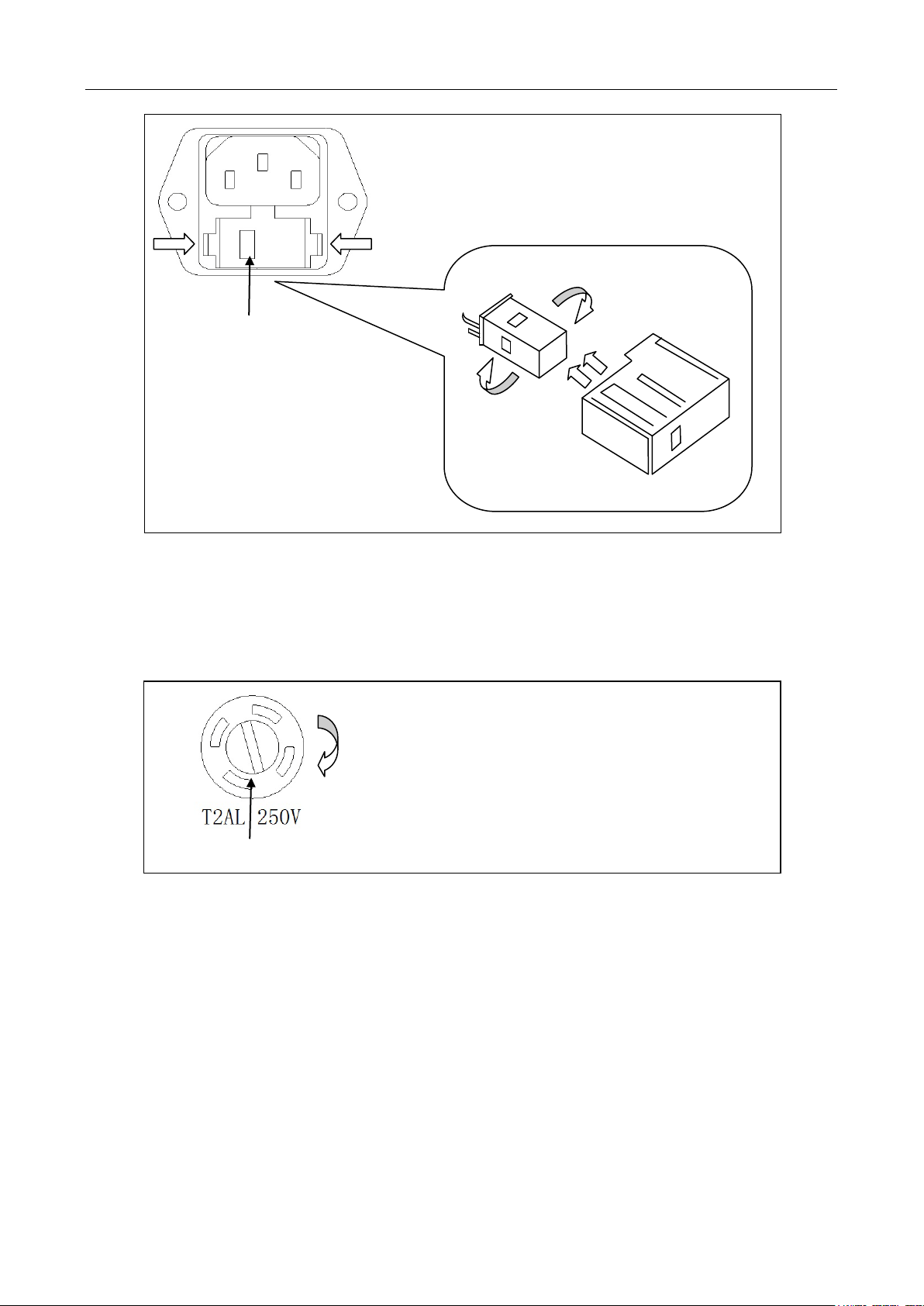
Fuse Box
110
remove fuse box.
Voltage Indicator Window
General information
Press both sides indicated by the arrows and pull to
Fuse Holder
220
110
Fuse Box
There is a second fuse with a fuse holder located in the front panel of the multimeter. This is an over
current protection fuse for the low current measurement input. It is rated for a T2AL, 250 V fuse. To
remove and replace this fuse, see the illustration below:
To remove, use a flat head screw driver or a coin to
insert into the slid and turn counter-clockwise to
open. Similarly to put back the fuse box, push the
box down and turn clockwise.
110
There is a third fuse locat ed ins ide the instrument which prot ects the 12 A input terminal if current
exceeds the maximum rat i ng. It is a 6 x 32 mm 250V, 20 A fast acting high energy ceramic fuse.
10
Page 11

General information
1.3 Package Contents
Please inspect the instrument mechanically and electrically upon receiving it. Unpack all items from
the shipping carton, and check for any obvious signs of physical damage that may have occurred
during transportation. Report any damage to the shipping agent immediately. Save the original
packing carton for possible future reshipment. Every meter is shipped with the following contents:
5492B/5492BGPIB 5½ digit multimeter
TL35B Test Leads (one set)
AC Power cord
Spare fuses
User Manual
USB Cable
Certificate of Calibration and Test Report
Verify that all items above are included in the shipping container. If anything is missing, please
contact B&K Precision.
11
Page 12
Overview
Chapter 2 Overview
This chapter is outlined as follows:
2.1 Front Panel Overview
2.2 Screen Display
2.3 Front Panel Menu Options
2.4 Front Panel Menu Overview
2.5 Rear Panel Summary
2.6 Power up
2.1 Front Panel Overview
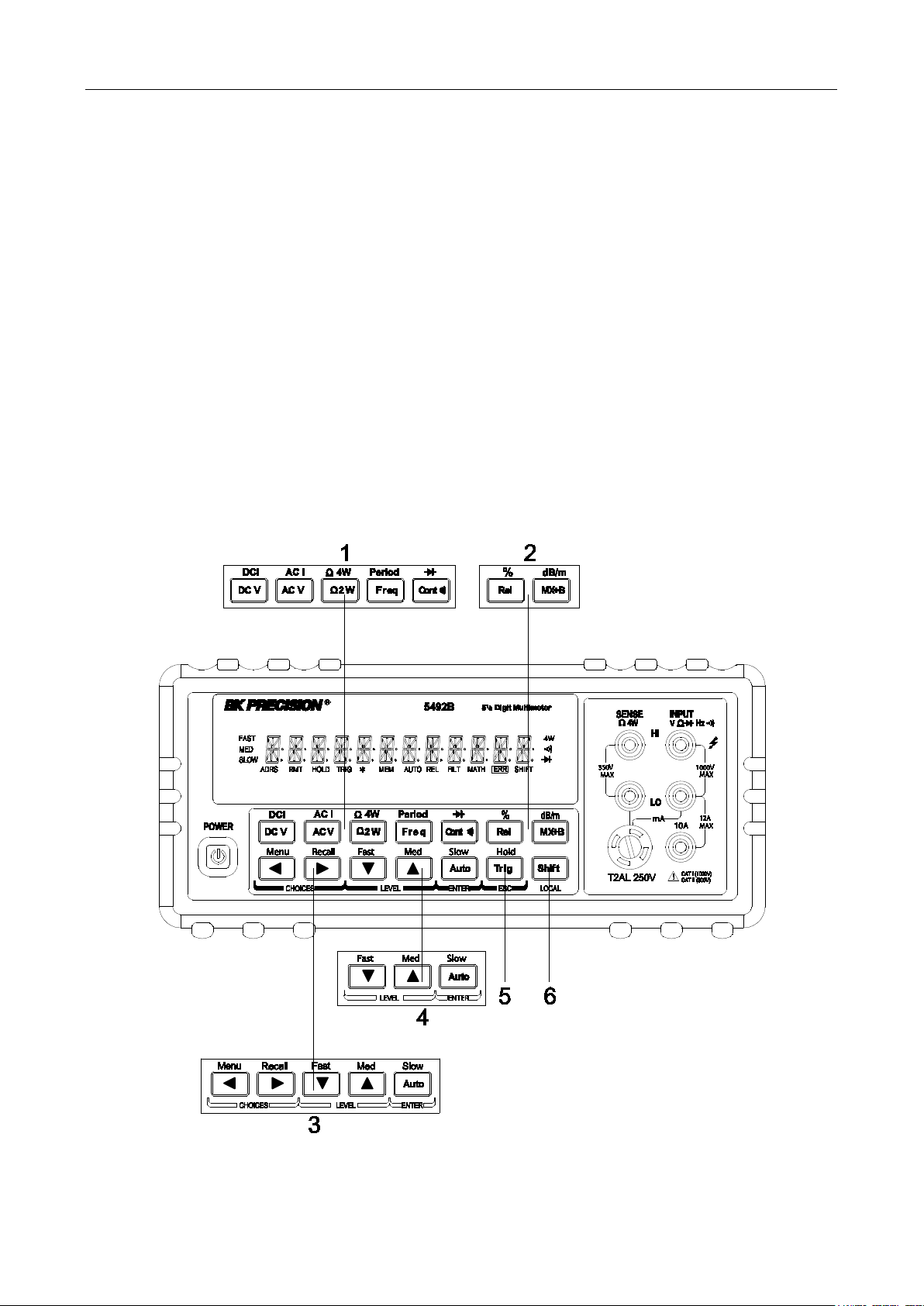
The front panel of the B&K 5492B is shown in Figure 2-1. This figure includes some important
abbreviated information that s hould be reviewed befor e oper ating the instrument.
Figure 1 - Front Panel View
12
Page 13
Overview
1. Measur ement function keys
Select measurement function: DC voltage and current, AC voltage and current, 2-wire and 4-wire
resistance, frequency, period, continuity and diode test.
2. Math function keys
Select math function: mX+b, %, dB, dBm and Rel.
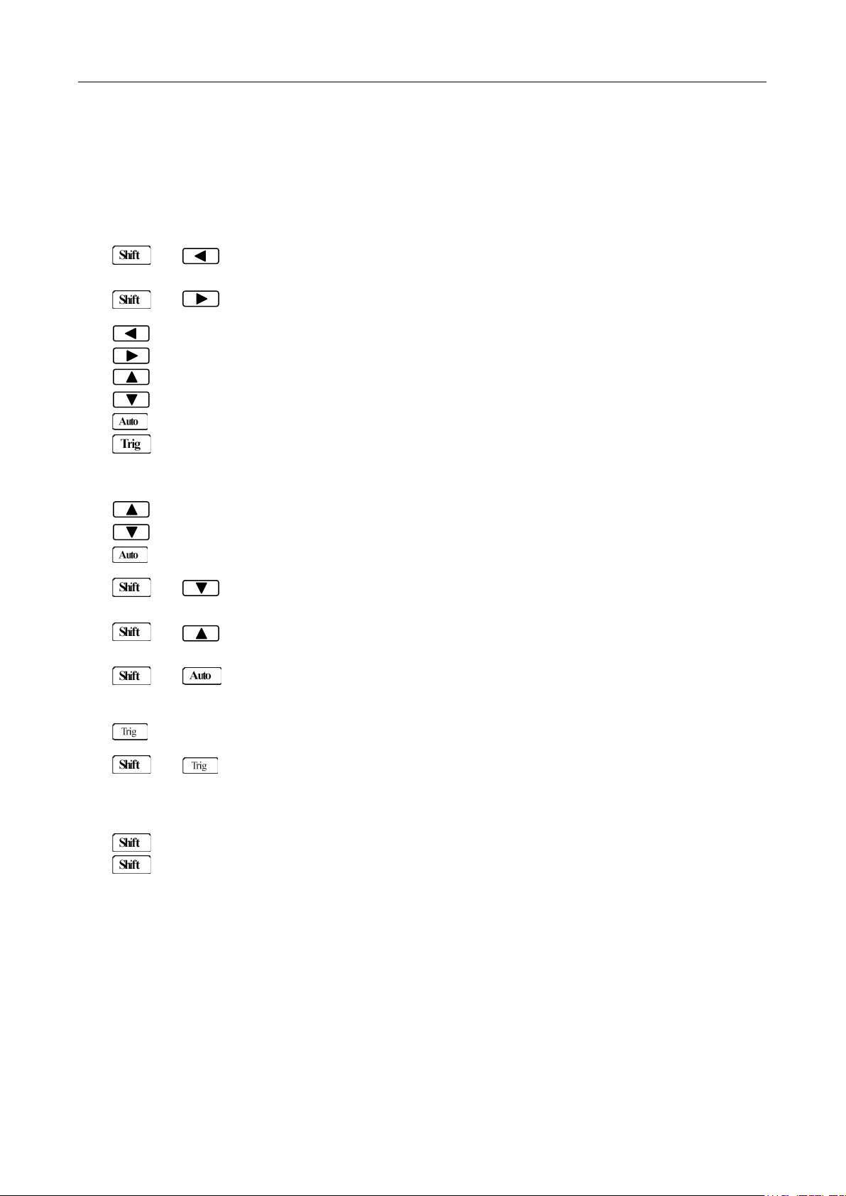
3. Menu oper ation key s
→ Open/Close menu
→ Recall the menu performed last
Move through selections within menu level, sub-menu level or parameter level
Move through se lections within menu level, sub-menu level or parameter level.
Move up a lev el.
Move down a level.
(ENTER) Save the changes made o n “parameter” level, and return to the “sub-menu” level.
(ESC) Cancel the changes made on “parameter” level, and return to the “sub-menu”
level.
4. Range and measure me nt speed keys
Select a higher range and disab le auto ranging.
Select a lower range and disable auto ranging.
T oggle between auto ranging and manual ranging.
→ Set measurement speed to Fast .
→ Set measurement speed to M edi um.
→ Set measurement speed to Slow.
5. T ri g/Ho ld Key
Trigger a measurement from the front panel.
→ Hold a stable reading on the display when selected numbers of samples are
6. Shift/Local keys
Used to access shifted keys (labels are in blue).
(LOCAL) Exit remote operation and set back to local oper ation.
within the selected toleran c e.
13
Page 14
Overview
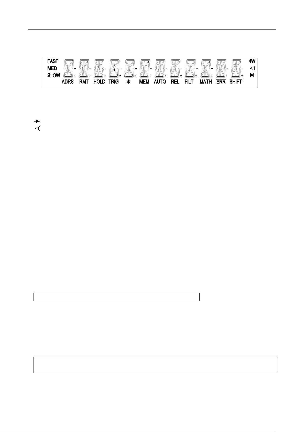
2.2 Screen Display
Figure 2-2 Display A nnunciator s
* (asterisk) Instrument is ready to st ore readi ngs ( w hen in system menu) /
Reading is being stored (w hen in measure ment mode)
(Diode) Instrument is in diode testing function
(Speaker) Beeper on for continuity testing function
4W Multimeter is in 4-wire resistance measurement mode.
ADRS Multimeter is addressed to listen or talk over the GPIB interface
AUTO Auto ranging enabled
ERR Hardware or remote control error detected
FAST Fast reading rate
FILT Digital filter enabled
HOLD Reading HOLD is enabled
MATH A math operation is enabled (mX+b, %, dB, dBm).
MED Medium reading rate
MEM Turns on when reading memor y is enabled
REL Relative reading displayed
RMT Multimeter is in remote mode
SHIFT Accessing shifted keys
SLOW Slow reading rate
TRIG Multimeter is wait ing for a trigger (manual, bus, or external trigger).
2.3 Front Panel Menu Options
A : MEA Surement MENU
1:CONTINUITY → 2:FILTER → 3:FILT TYPE → 4:FILT COUNT
1. CONTINUITY Select the continuity beeper threshold: 1 Ω to 1000 Ω
2. FILTER Enable or disable FILTER function.
3. FILT TYPE Select the type of filter.
Select MOVNG AV (Moving Average) or REPEAT (Repeating Average).
4. FILT COUNT Set the number of readi ngs to be filtered or averaged.
B : MATH MENU
1:SET M → 2:SET B → 3:PERCENT → 4:dB REF → 5:dBm REF → 6:LIMIT TEST → 7:HIGH LIMIT
→ 8:LOW LIMITT→ 9:LIMIT BEEP
1. SET M Set the scale factor M for MX+B fun ct ion.
2. SET B Set the offset factor B for MX+B function.
14
Page 15

Overview
3. PERCENT Set the reference value for PERCENT function.
4. dB REF Set the dB reference voltage value.
5. dBm REF Set the dBm reference impedance value.
6. LIMIT TEST Enable or disable the limit testing.
7. HIGH LIMIT Set the high limit for limit test ing.
8. LOW LIMIT Set the low limit for limit testing.
9. LIMIT BEEP Set the beep mode for limit testing. Select from: NEVER, HI, IN, LO, OUT.
C : TRIGger MEN U
1:TRIG MODE → 2:TRIG DELAY
1. TRIG MODE Select the trigger source.
Select IMM (Immediate), MAN (Manual), BUS, or EXT (External) trigger
source.
2. TRIG DELAY Select AUTO or MANUal trigger delay mode. Selecting manual will allow
you to specify a time interval which is ins er t ed before a measure ment.
D : SYStem MENU
1:RDGS STORE → 2:RDGS COUNT → 3:SAVED RDGS → 4:BEEP →5:SAVE CNFG
→ 6:LOAD CNFG → 7:DISPLAY → 8:KEY SOUND → 9:TEST
1. RDGS STORE Enable or disable reading me m or y.
2. RDGS COUNT Set the number of readings to be saved (2 to 512).
3. SAVED RDGS Recall readings stored in memory.
4. BEEP Enable or disable the beeper fu nction
5. SAVE CNFG Save the present configuration as one of the 10 user’s settings.
6. LOAD CNFG Restore factory or one of the 10 user’s settings
7. DISPLAY Enable or disable the front panel display.
8. KEY SOUN D Enable or disable the key sound w hen you press a key.
9. TEST Perform a complete sel f-test.
E : Input / Outp ut MENU
1:GPIB ADDR → 2:INTERFACE → 3:BAUD RATE→ 4:PARITY→ 5:TX TERM→ 6:RETURN
1. GPIB ADDR Set the GPIB bus address. (0 to 31)
2. INTERFACE Select between GPIB and USB/RS232 as the remote control inter face.
3. BAUD RATE Select the baud rate for USB/RS232C operation.
Select from: 115.2K, 57.6K, 38.4K, 19.2K, 9600,4800, 2400.
4. PARITY Select the parity mode for USB/RS232C operation.
Select from: NONE, EVEN, ODD.
5. TX TERM Select the terminal char acter for USB/RS232C communication.
Selection from: LF, CR, LFCR
6. RETURN Enable or disable echoing command strings.
F : CALibrati on MEN U (This function is not available)
1:SECURED → 3:CAL DATE → 4:CAL COUNT
15
Page 16
Overview
level is too small for the
selected command. The minimum value allowed is displayed for you to
level is too large for the
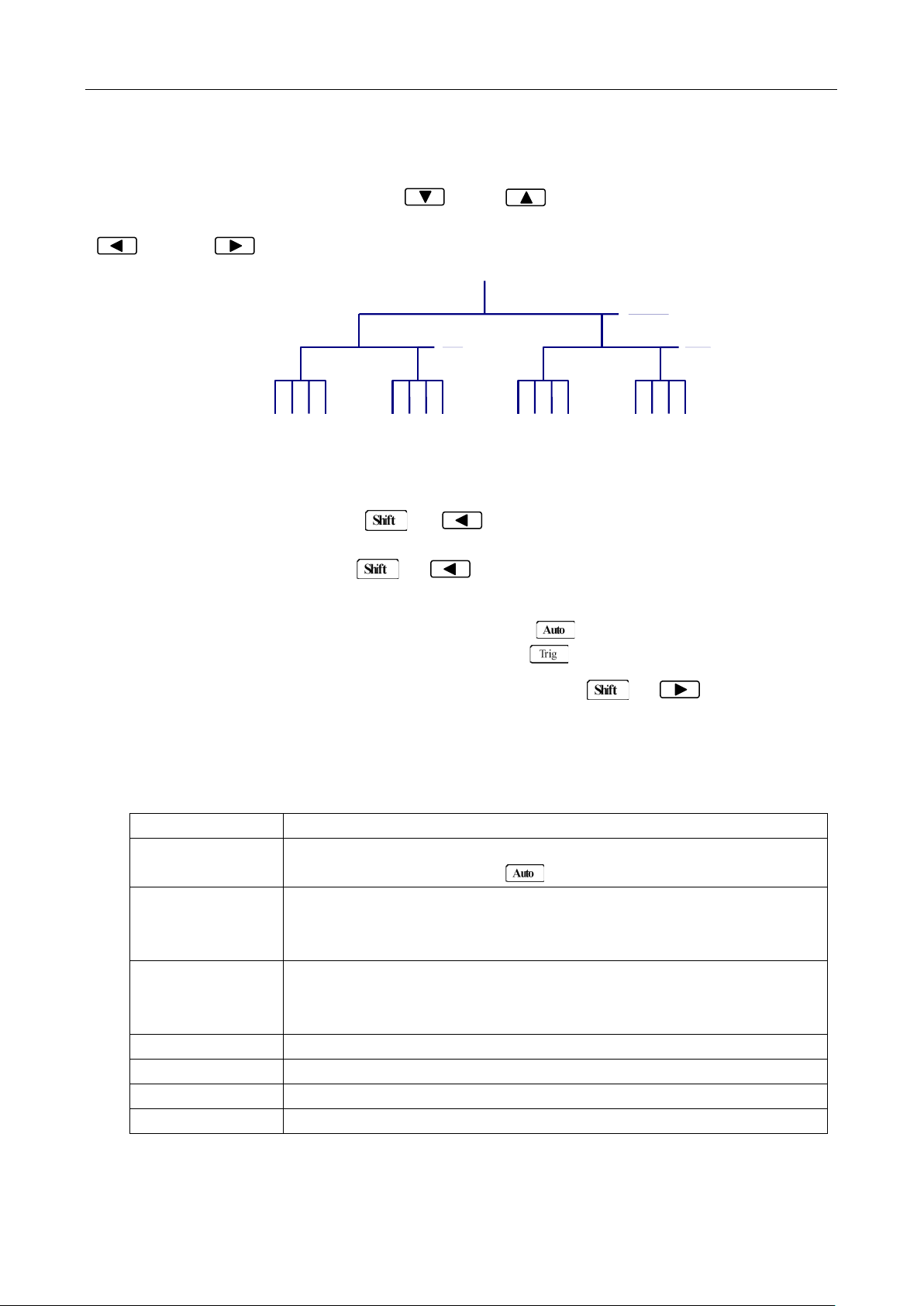
2.4 Front Panel Men u Overvie w
The menu is organized in a top-down tree struc ture with three levels ( m enus, submenus and parameter s)
as shown in Figure 2-3. You can use down ( ) or up ( ) keys to browse through the menu tree
from one level to another. Each of the three levels has several choices which you can view by using left
( ) or right ( ) keys.
T o t ur n on t he menu, press → (Menu).
Submenus
Parameters
Menus
Figure 2-3 Menu Tree
T o t ur n off the menu, press → (Menu), or press any of the function or math keys
on the top row of front panel keys (i.e. DC V, Freq, etc.).
To confirm a change on the “parameter” level, press (ENTER).
T o cancel a change on the “parameter” level, press (ESC).
T o r ecall the last menu com m and t hat w as executed, press → (Recall)
The messages display ed during menu operation are listed in the following Table 2-1.
Table 2-1 Messages Displayed During Menu Operation
MESSAGES DESCRIPTION
CHANGE SAVED
TOO SMALL
TOO LARGE
FILE SAVING
FILE LOADING
SAVE SUCCEED
LOAD SUCCEED
The change made on the “parameter” level is saved. This message will
be displayed after you press (ENTER) to save the changes.
The value you specified on the “parameter”
edit.
The value you specified on the “parameter”
selected command. The maximum value allowed is displayed for you to
edit.
System configuration file is being saved.
System configuration fil e i s being restored.
System configuration file is successfully saved.
System configuration file is successfully restored.
16
Page 17
Overview
Note: If you press on the “menu” level, nothing will happen because it is at the top
menu level of already. Likewise, if you press on the “parameter” level, nothing will
happen because it is at the l ow est menu level.
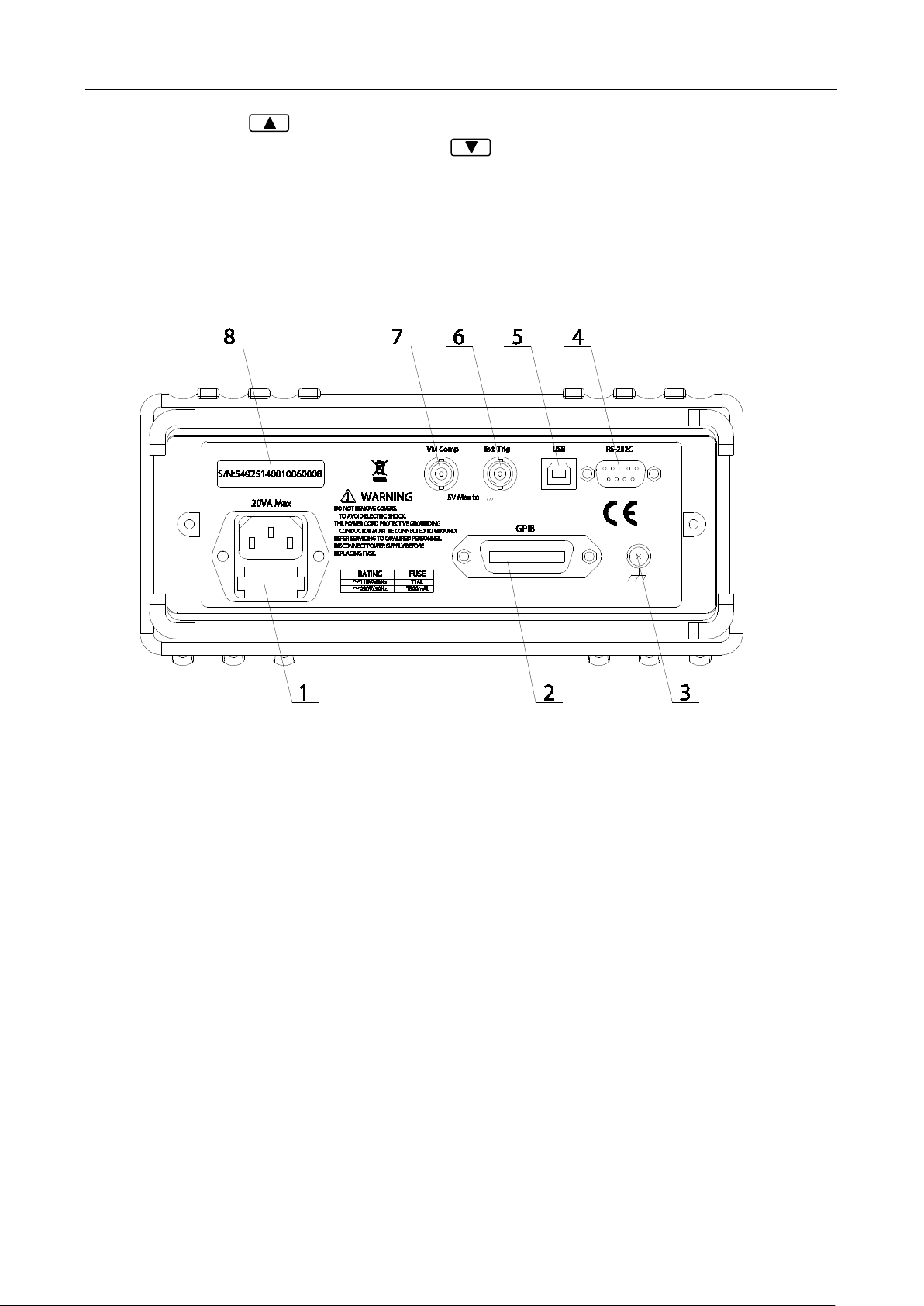
2.5 Rear Panel Summary
The rear panel of BK 5492B is shown in Figure 2-4. This section includes important information that
should be reviewed before oper ating the instrument.
Figure 2-4 Rear Panel
1. Power line fuse holder
The multimeters can be configured for line v oltage of 110/220 V ± 10 % AC at line frequency of 50/60
Hz ± 5%.
Power line fuse is used for instru ment pr ot ection. (220 V/500 mA or 110 V/1 A)
Note: Please use the same-type of fuse as it is in the fuse holder. To verify and replace the
fuse, remove the power cable and pull out the fuse holder. See section 1.2 for
details.
2. (optional) GPIB (IEEE-488) interface (model 5492BGPIB)
3. Chassis ground screw terminal
4. RS-232 (Serial) interface
5. USB interface
6. External Tr igger BN C inpu t terminal
7. VM Comp (Voltmeter complete) BNC output terminal
8. Serial number label
17
Page 18

Overview
2.6 Power up
2.6.1 Power Line Connection
CAUTION: Operating the instrument on an incorrect line voltage may cause damage to the
instrument, possibly voidi ng the warranty.
BEFORE
in place, and the fuse box inside the fuse holder is adjusted correctly. See section for
details.
Follow the procedure below to connect the 5492B to line p ow er and turn on the instrument.
1. Check the line voltage and be sure it is within the acceptable range of the meter
2. Check the fuse box position inside the fuse hol der to make sure it is in the correct position that
3. Check that the correct line fuse is properly inserted into the fuse box. The f use rating between
4. Before plugging in the power cord, make sure that the front panel power switch is in the off (out)
5. Connect the female end of the supplied power cord to the AC input on the rear panel. Connect the
WARNING: The power cord supplied with the Model 5492B contains a separate ground wire for
6. Turn on the instrument by pressing the front panel pow er switch.
connecting the 5492B multimeter to a power line, please check that the correct fuse is
1.2
BEFORE
connecting into the AC input in the rear panel of the instrument. Applying an incorrect voltage
may cause damage to the instrument and void its warranty.
corresponds to the line voltage the unit will be connected to. The fuse holder will have a selected
voltage label on the front to indicate the selected voltage tab for operation. Change the fuse box
position to change between 110 and 220. If you’re not sure, see section
1 10V and 220V operation is different. Refer to section 1.2 for details.
position.
other end of the power cord to a grounded AC outlet.
use with grounded outlets. When proper connections are made, instrument chassis
is connected to power li ne gr ou nd thr ou g h the gr ound wi re i n the p owe r cord. F ail ur e
to use a grounded outlet may r esul t i n personal injury or death due to electric shock.
1.2 for details.
2.6.2 Power-up Sequence
On power-up, the multimeter performs self-tests on its EPROM and RAM and lights all segments and
annunciators for about 1 second. If a failure is detected, the instrument momentarily displays an error
message and the ERR an nunciator will turn on.
If the instrument passes self-tests, the firmware version and the model number will display momentarily
before it is ready for use.
18
Page 19

Overview
2.6.3 High Energy Circuit Safety Precautions
To optimize safety when measuring voltage in high energy distribution circuits, read and use the
directions in the following warning.
WARNIG: Dangerous arcs of an explosive nature in a high energy circuit can cause severe
personal injury or death. If the multimeter is connected to a high energy circuit
when set to a current range, low resistance range, or any other low impedance
range, the circuit is virtually shorted. Dangerous arcing can result even when the
multimeter is set to a voltage range if the minimum voltage spacing is red uced i n the
external connections.
When making measurements in high energy circuits, use test leads and accessories that meet the
following requirements:
T est lea ds and a ccessor ie s must be fully insulate d and adhere to proper ANSI IEC CA T r ating s.
Do not use test leads or accessories that decrease voltage spacing. This diminishes arc
protection and creates a hazardous condition.
WARNING: The maximum common-mode voltage (voltage between INPUT LO and the chassis
ground) is 5 00 V peak. Exceeding this value may cause a breakdown in insulation,
creating a shock hazard.
2.6.4 Power-on Defaults
The multimeter uses the fact or y default settings for t he pow er-on settings.
All the procedures in this manual assume factory default settings, therefore reset the instrument to the
factory settings when following the step-by-step procedures in later sections. Table 2-2 lists the factory
default settings.
19
Page 20

Setting Factory Default
Autozero
Buffer
Continuity
Beeper
Digits
Rate
Threshold
Current(AC and DC)
Digits(AC)
Digits(DC)
Filter
Count
Mode
Range
Relative
Value
Rate(AC)
Rate(DC)
Diode test
Digits
Range
Rate
Frequency and Period
Digits
Range
Relative
Value
Rate
Function
GPIB
Address
Language
Limits
Beeper
High limit
Low limit
mX+b
Scale factor
Offset
Percent
Reference
Overview
Table 2-2 Factory Default Settings
On
No effect
On
4 1/2
Fast(0.1 PLC)
10 Ω
5 1/2
5 1/2
On
5
Moving average
Auto
Off
0.0
Medium(10PLC)
Medium( 1 PLC)
5 1/2
1 mA
Medium(1 PLC)
5 1/2
12 V
Off
0.0
Slow(1 sec)
DCV
No effect
8
SCPI
Off
ON
+1
-1
Off
1.0
0.0
Off
1.0
20
Page 21

Table 2-2 Factory Default Settings (cont.)
Resistance(2-wire and 4-wire)
Digits
Filter
Count
Mode
Range
Relative
Value
Rate
RS-232(USB)
Baud
Triggers
Continuous
Delay
Source
Volta ge( AC and DC)
dB reference
dBm reference
Digits(AC)
Digits(DC)
Filter
Count
Mode
Range
Relative
Value
Rate(AC)
Rate(DC)
Overview
5 1/2
On
5
Moving average
Auto
Off
0.0
Medium(1 PLC)
On
9600
On
Auto
Immediate
No effect
75 Ω
5 1/2
5 1/2
On
5
Moving average
Auto
Off
0.0
Medium(10PLC)
Medium( 1PLC)
2.6.5 Warm-up time
The 5492B is ready for use after power-up sequence (boot and self test) is completed. However, to
achieve specified accuracy and stability, allow the instrument to warm up for half an hour. If the
instrument has been subjected t o extreme temperat ures, allow add itiona l time for internal te mperature to
stabilize
21
Page 22

Basic Measurements
Chapter 3 Basic Measurements
This chapter is outlined as follows:
3.1 Overview
3.2 Measuring Vol tage
3.3 Measuring Current
3.4 Measuring Resistance
3.5 Measuring Frequency and Period
3.6 Measuring Continuity
3.7 Tes ting Di ode
3.8 Math Functions
3.1 Overview
The front panel has two rows of keys to select various functions and operations. Most keys have a
shifted function printed in blue above the key. To perform a shifted function, press (the Shift
annunciator will turn on). Then, press the key that has the desired label above it. For example, to select
the AC current function, press then press (AC I).
If you accidentally press , just press it again to tur n off the Shift annunciator.
3.2 Measuring Voltage
Voltage ranges: 120 mV, 1.2 V, 12 V, 120 V, 1000 V (750 VAC)
Maximum resolution: 1 μV (on 120 mV range)
3.2.1 Connections
Assuming the multimeter is under factory default conditions, the basic procedure for measuring voltage
is as follows:
1. Connect test leads to INPUT HI and LO ter m in als.
2. Select DC or AC voltage measurement by pressing or respectively.
3. Press to toggle between auto and manual ranging. Notice the AUTO annunciator is
displayed with auto ranging. For manual range, use the RANGE and keys to select
the appropriate range for meas urement.
4. Connect test leads to the sources as shown in Figure 3-1.
CAUTION: Do not apply more t han 1000 V peak to the input or it will damage the instrument.
5. If the “OVR.FLW” message is displayed, press the up key to select a higher range until a
normal reading is displaye d (or press key for auto ranging). Use t he lowest poss ible range for
the best resolution. The measured reading is displayed.
22
Page 23

Basic Measurements
DC Voltage
Source
▲
▲
▲
▲
DC V AC V 2W Fr eq
Aut o
Tr i
g
MX+ B
Shi f t
Cont Rel
¦¸
Period
dB/m
FastMenu Recall Med Slow Hold
CHOICES
LEVEL
ENTER
ESC
LOCAL
%
IDC IAC 4W
Ω
FAST
MED
SLOW
ADRS RMT HOLD TRIG
*
MEM AUTO
REL FILT MATH SHIFT
4W
ERR
POWER
T2AL 250V
SENSE
V
Ω
LO
HI
!
10A
CATⅡ(300V)
CATⅠ(1000V)
350V
MAX
1000V
MAX
12A
MAX
mA
12A
INPUT
R
5
5492B
1
2
/
Digit Multimeter
1000V
MAX
AC Voltage
Source
▲
▲
▲
▲
DC V AC V 2W Fr eq
Aut o
Tr i
g
MX+ B
Shi f t
Cont Rel
¦¸
Period
dB/m
FastMenu Recall Med Slow Hold
CHOICES LEVEL ENTER
ESC
LOCAL
%
IDC IAC 4W
Ω
FAST
MED
SLOW
ADRS RMT HOLD TRIG
*
MEM AUTO REL FILT MATH SHIFT
4W
ERR
POWER
T2AL 250V
SENSE
Ω
4W
V
Ω
LO
HI
!
10A
350V
MAX
12A
MAX
mA
12A
INPUT
CATⅡ(300V)
CATⅠ(1000V)
R
5
5492B
1
2
/
Digit Multimeter
Input Resistance = 10 MΩ on 1000 V and 120 V ran ges;
> 10 GΩ on 12 V, 1.2 V and 120 mV ranges
CAUTION: Maximum Input = 1010 V peak
CAUTION: Maximum Input = 750 V RMS or 1000 V peak
Input Impedance = 1 MΩ,100 pF
Figure 3-1 DC and AC Voltage Measurement Connections
23
Page 24

Basic Measurements
3.2.2 Crest factor
AC voltage and current accurac ies are affected by the crest factor of the waveform, the ratio of the pea k
value to the RMS value. Table 3-1 lists the fundamental frequencies at which the corresponding crest
factor must be taken into accou nt for accuracy calculations.
Table 3-1 Crest Factor Limitations
Crest Factor Fundamental Frequency
2
3
4-5
50 kHz
3 kHz
1 kHz
3.3 Measuring Current
Current ranges: 12 mA, 120 mA (DCI only, not available for ACI), 1.2 A, 12 A
Maximum resolution: 100 nA (on 12 mA range)
Note: Auto range is only avail able f or 12 m A an d 120 mA ( DCI o nly ) ranges. For 1.2 A and 12 A
range, manual range must be used.
3.3.1 Connections
Assuming the multimeter is under factory default conditions, the basic procedure for measuring current
is as follows:
1. Connect test leads to INP UT LO and SENSE LO terminals
2. Select DCI or ACI measurement function by pressing → or →
respectively.
3. Press to toggle between auto and manual ranging. Notice the AUTO annunciator is displayed
with auto ranging. For manual range, use the RANGE and keys to select a
measurement range consistent with expected curre nt.
Auto range is onl y av ai lable for 12 mA and 120 mA (DCI only) ranges. Manual range must be
used for 1.2 A and 12 A ranges.
Therefore, it is recommended to use manual range when measuring current greater than 1 A with
1.2 A or 12 A range.
4. Connect test leads to the s ourc e as shown in Figure 3-2:
CAUTION: Do not apply more than 2 A between INPUT LO and SENSE LO terminals or the
protective fuse on the front panel will blow. Use the 10 A terminal for measuring
current above 1 A. See Figure 3-2 for details.
5. If the “OVR.FLW” message is displayed, press up key to select a higher range until a normal
reading is displayed (or press key for auto ranging). Use the lowest possible range for the
best resolution. Note that auto ranging is only av ailable for 12 mA and 120 mA (DCI only) ranges.
24
Page 25

Basic Measurements
CATⅡ(300V)
CATⅠ(1000V)
1000V
MAX
Current Source
▲
▲
▲
▲
DC V AC V 2W Freq
Aut o
Tr i
g
MX+ B
Shi f t
Cont Rel
¦¸
Period
dB/m
FastMenu Recall Med Slow Hold
CHOICES
LEVEL
ENTER
ESC
LOCAL
%
IDC IAC 4W
Ω
FAST
MED
SLOW
ADRS RMT HOLD TRIG
*
MEM AUTO REL FILT MATH SHIFT
4W
ERR
POWER
T2AL 250V
SENSE
Ω
4W
V
Ω
HI
!
10A
CATⅡ(300V)
350V
MAX
12A
MAX
mA
12A
INPUT
R
5
5492B
1
2
/
Digit Multimeter
1000V
MAX
12A
MAX
12A
Current Source
▲
▲
▲
▲
DC V A C V 2W Fr eq
Aut o
Tr i
g
MX+ B
Shi f t
Cont Rel
¦¸
Period
dB/m
FastMenu Recall Med Slow Hold
CHOICES
LEVEL
ENTER
ESC
LOCAL
%
IDC IAC 4W
Ω
FAST
MED
SLOW
ADRS RMT HOLD TRIG
*
MEM AUTO
REL FILT MATH SHIFT
4W
ERR
POWER
T2AL 250V
SENSE
Ω
4W
V
Ω
LO
HI
!
10A
CATⅡ(300V)
CATⅠ(1000V)
350V
MAX
mA
INPUT
R
5
5492B
1
2
/
Digit Multimeter
For low current measurement: INPUT LO and SEN SE LO terminals are used.
CAUTION: Maximum input = 1 A DC or RMS
For 1 A or higher current measurement: 10 A and INPUT LO terminals are used.
CAUTION: Maximum Input = 12 A DC or RMS
Note: Auto range is not available for 1.2 A and 12 A ran ges
Figure 3-2 DC and A C Current Measurements
3.3.2 Front Panel Fuse Replacement
WARNING: Make sure the instrument is disconnected from the power line and other equipment
before replacing the fus e.
1. Turn of f t he power and disconnect the power line and test leads.
2. From the front panel, use a screwdriver to rotate the fuse holder several turns counter-clockwise.
Take the fuse carrier out of the socket.
3. Remove the fuse and replac e it w it h t he same type (T2AL, 250 V, 5×20mm)
CAUTION: Do not use a fuse with a higher current rating than specified or instrument damage
may occur. If the instrument repeatedly blows fuses, try to find out the reason
before replacing the fus e.
25
Page 26

Basic Measurements
To remove, use a flat head screw driver or a coin to
insert into the slid and turn counter-clockwise to
open. Similarly to put back the fuse box, push the
box down and turn clockwise.
110
Fuse Box
3.4 Measuring Resistance
Resistance measurement r ange: 120 Ω, 1.2 kΩ, 12 kΩ, 120 kΩ, 1.2 MΩ, 12 MΩ, 120 MΩ
Maximum resolution: 1 mΩ (on 120 Ω range)
3.4.1 Connections
Assuming the multimeter is under factory default conditions, the basic procedure for measuring
resistance is as follows:
1. Connect test leads to the multimeter as follows:
A: For Ω2-wire, connect the test leads to INPUT HI and LO .
B: For Ω4-wire, connect the test leads to INPUT HI and LO, and SENSE Ω 4W HI and LO. Kelvin
test probes are recommended for this setup.
2. Select Ω 2-wire or Ω 4-wire measurement function by pressing or →
respectively.
3. Press to toggle between auto and manual ranging. Notice the AUTO annunciator is
displayed with auto ranging. For manual range, use the RANGE and keys to select a
measurement range.
4. Connect test leads to the r esist ance as shown in Figure 3-3:
CAUTION: Do not apply more than 1000 V peak between INPUT HI and LO or it will damage the
instrument
5. If the “OVR.FLW” message is di spla yed, press up key to select a higher range until a normal
reading is displayed (or press key for auto ranging). Use the lowest possible range for the
best resolution.
6. The measured reading is displayed.
26
Page 27

Basic Measurements
Shielded
Coble
Optional
Shield
Resistance
Under Test
▲
▲
▲
▲
DC V A C V 2W Fr eq
Aut o
Tr i
g
MX+ B
Shi f t
Cont Re l
¦¸
Period
dB/m
FastMenu Recall Med Slow Hold
CHOICES
LEVEL ENTER
ESC
LOCAL
%
IDC IAC 4W
Ω
FAST
MED
SLOW
ADRS RMT HOLD TRIG
*
MEM AUTO
REL FILT MATH SHIFT
4W
ERR
POWER
T2AL 250V
SENSE
Ω
4W
V
Ω
LO
HI
!
10A
CATⅡ(300V)
CATⅠ(1000V)
350V
MAX
1000V
MAX
12A
MAX
mA
12A
INPUT
R
5
5492B
1
2
/
Digit Multimeter
T2AL 250V
SENSE
Ω
4W
V
Ω
LO
HI
!
10A
CATⅡ(300V)
CATⅠ(1000V)
350V
MAX
1000V
MAX
12A
MAX
mA
12A
INPUT
Shielded
Coble
Optional
Shield
Resistance
Under Test
▲
▲
▲
▲
DC V AC V 2W Fr eq
Aut o
Tr i
g
MX+ B
Shi f t
Cont Re l
¦¸
Period
dB/m
FastMenu Recall Med Slow Hold
CHOICES
LEVEL
ENTER ESC
LOCAL
%
IDC IAC 4W
Ω
FAST
MED
SLOW
ADRS RMT HOLD TRIG
*
MEM AUTO REL FILT MATH SHIFT
4W
ERR
POWER
R
5
5492B
1
2
/
Digit Multimeter
Note: Source current flows from the INPUT HI to INPUT LO terminals
Note: Source current flows from the INPUT HI to INPUT LO terminals
Figure 3-3 Two- and Four- wire Resistance Measurements
3.4.2 Shielding
To achieve a stable accurate reading, it helps to shield resistances greater than 100 kΩ. Place the
resistance in a shielded enclosure and connect the shield to the INPUT LO terminal of the instrument
electrically.
27
Page 28

Basic Measurements
3.5 Measuring Frequenc y and Period
Frequency measure me nt r ange: 5 Hz to 1 MHz.
Period measurement range: 0.2 s to 1 μs.
Input signal range: 120 mV AC to 750 V AC RMS.
The instrument uses the volts input terminals (INPUT HI and INPUT LO) to measure frequency and
period. The AC voltage range can be changed with the RANGE and keys. However, the
signal voltage must be greater than 10% of the full-scale range.
Note: Auto ranging is not avail a bl e f or frequency and pe r iod measurement function.
3.5.1 Trigger Level and Measurement Errors
Frequency and Period apply a zero-crossing trigger, meaning that a count is taken when the signal
crosses the zero level.
The multimeter uses an interactive counting technique to measure frequency and period. This method
generates constant measurement resolution for any input frequency. All frequency counters are
subject to e rrors when measuring low voltage, low frequency signals. Both internal noise and external
noise are also critical when measuring low voltage, low frequency signals. Measurement errors will
also occur if you attempt to measure the frequency (or period) of an input following a dc offset voltage
change. You must allow the multimeter’s DC input blocking capacitor to fully settle before making
frequency measureme nt s.
3.5.2 Gate Time
Gate time is the amount of time the multimeter uses to sample frequency or period readings. For model
5492B, all RATE settings (Fast, Med and Slow) y ield a gate time of one second.
3.5.3 Connections
Assuming the multimeter is under factory default conditions, the basic procedure for measuring
frequency or period is as follows:
1. Connect test leads to INP UT HI and LO terminals.
2. Select frequency or period measurement functions by pressing or →
respectively.
3. Connect test leads to the sour ce as shown in Figure 3-4:
CAUTION: Do not exceed 1000 V peak between INPUT H I and INPUT LO or instrument damage
may occur.
4. The measured reading is displayed.
28
Page 29

Basic Measurements
T2AL 250V
SENSE
Ω
4W
V
Ω
LO
HI
!
10A
CATⅡ(300V)
CATⅠ(1000V)
350V
MAX
1000V
MAX
12A
MAX
mA
12A
INPUT
AC Voltage
Source
▲
▲
▲
▲
DC V A C V 2W Fr eq
Aut o
Tr i
g
MX+ B
Shi f t
Cont Re l
¦¸
Period
dB/m
FastMenu Recall Med Slow Hold
CHOICES
LEVEL ENTER
ESC
LOCAL
%
IDC IAC 4W
Ω
FAST
MED
SLOW
ADRS RMT HOLD TRIG
*
MEM AUTO
REL FILT MATH SHIFT
4W
ERR
POWER
R
5
5492B
1
2
/
Digit Multimeter
Input Impedance = 1 MΩ in parallel with <100 pF
CAUTION: Maximum Input = 750 RMS, or 1000 V Peak
Figure 3-4 Frequency and Period Measurements
3.6 Measuring Continuity
The multimeter uses the 1 kΩ range to measure circuit continuity. A threshold resistance level (1 Ω to
1000 Ω) sh ould b e set. The factory default value is 10 Ω. The multimeter alerts you with a beep wh en a
reading is below the set lev el.
Note: Continuity function defaults to FAST (0.1 PLC) rate and cannot be changed.
3.6.1 Connections
Assuming the multimeter is under factory default conditions, the basic procedure for continuity testing is
as follows:
1. Connect test leads to the INPUT HI and LO terminals.
2. Select Continuity measurement function by pressing .
3. Connect test leads to the r esist ance under test as shown in Figure 3-5.
4. The measured reading is displayed.
29
Page 30

Basic Measurements
T2AL 250V
SENSE
Ω
4W
V
Ω
LO
HI
!
10A
CATⅡ(300V)
CATⅠ(1000V)
350V
MAX
1000V
MAX
12A
MAX
mA
12A
INPUT
Resistance
Under Test
▲
▲
▲
▲
DC V AC V 2W Freq
Aut o
Tr i
g
MX+ B
Shi f t
Cont Rel
¦¸
Period
dB/m
FastMenu Recall Med Slow Hold
CHOICES
LEVEL
ENTER
ESC
LOCAL
%
IDC IAC 4W
Ω
FAST
MED
SLOW
ADRS RMT HOLD TRIG
*
MEM AUTO
REL FILT MATH SHIFT
4W
ERR
POWER
R
5
5492B
1
2
/
Digit Multimeter
Note: Source current flows from the INPUT HI to INPUT LO terminals.
Figure 3-5 Continuity Measurement
3.6.2 Threshold resistance level
You can define a threshold resista nce from 1 Ω to 1000 Ω. Factory default value is 10 Ω. Follow the steps
below to define the resistance level:
1. Press for Continuity Measurement.
2. Press → to enter the submenu level, “1: CONTINUITY” will be displayed.
3. Press to enter the parameter level, the current LEVEL value will be displayed.
4. Use and keys to change the cursor position and use and keys to
increment or decrement the digits respectively. Enter a value from 1 to 1000.
5. Press (ENTER) to confirm your setting. Message “CHANGE SAVED” will be displayed for a
moment.
6. Press or → to exit the menu and return to the continuity measurement.
3.7 Testing Diode
The multimeter can also be used to measure the forward voltage drop of general-purpose diodes and
the zener voltage of zener diodes. A current range (1 mA, 100 μA, or 10 μA) can be selected for diode
measurement.
Note: Diode testing defaults to MED (1 P LC) rate and cannot be c hanged.
3.7.1 Connections
Assuming the multimeter is under factory default conditions, the basic procedure for diode testing is as
follows:
1. Connect test leads to INP UT HI and LO terminals.
2. Press → for diode measurement function.
3. Connect test leads to the diode under test as shown in Figure 3-6.
4. Take a reading from the display.
30
Page 31

Basic Measurements
T2AL 250V
SENSE
Ω
4W
V
Ω
LO
HI
!
10A
CATⅡ(300V)
CATⅠ(1000V)
350V
MAX
1000V
MAX
12A
MAX
mA
12A
INPUT
Diode
▲
▲
▲
▲
DC V AC V 2W Fr eq
Aut o
Tr i
g
MX+ B
Shi f t
Cont Re l
¦¸
Period
dB/m
FastMenu Recall Med Slow Hold
CHOICES
LEVEL
ENTER
ESC
LOCAL
%
IDC IAC 4W
Ω
FAST
MED
SLOW
ADRS RMT HOLD TRIG
*
MEM AUTO
REL FILT MATH SHIFT
4W
ERR
POWER
R
5
5492B
1
2
/
Digit Multimeter
T2AL 250V
SENSE
Ω
4W
V
Ω
LO
HI
!
10A
CATⅡ(300V)
CATⅠ(1000V)
350V
MAX
1000V
MAX
12A
MAX
mA
12A
INPUT
Zener
diode
▲
▲
▲
▲
DC V AC V 2W Fr eq
Aut o
Tr i
g
MX+ B
Shi f t
Cont Re l
¦¸
Period
dB/m
FastMenu Recall Med Slow Hold
CHOICES
LEVEL ENTER
ESC
LOCAL
%
IDC IAC 4W
Ω
FAST
MED
SLOW
ADRS RMT HOLD TRIG
*
MEM AUTO
REL FILT MATH SHIFT
4W
ERR
POWER
R
5
5492B
1
2
/
Digit Multimeter
Note: Source current flows from the INPUT HI to INPUT LO terminals
Figure 3-6 Diode Measurement
3.7.2 Current Range
You can set the test current range from the front panel. The choices are 1 mA, 100 μA, and 10 μA. The
factory default current range is 1 mA. To set the test current, follow the steps below:
1. Press → for diode measurement function
2. Using and keys to scroll through the thr ee t est c ur rent selections.
The diode test function measures vol tage on the 3V range for the 1 mA test current and the 10 V range
for the 100 μA and 10 μA ranges. If a reading is more than 10V, the multimeter will display the
“OVR.FLW” message.
31
Page 32

Basic Measurements
3.8 Math Functions
The multimeter math operat ions are divided into four categories:
mX+b and percent
dB and dBm calculations
Statistics of buffered readings
Limit testing
The first two categories are discussed here in this section, while buffered reading statistics and reading
limit testing are described in the next chapter, “Measurement Options”.
Notes: Once math is enabled for a function, the mX+b and percentage calculations will take
effect across funct i on changes.
3.8.1 mX+b
This math operation lets you manipulate normal display readings (X) mathematically according to the
following calculation:
Y = mX + b
Where: X is the nor m al ly display actual reading
m and b are user-entered constants for scale factor and offset respectively
Y is the displayed result
To configure the mX+b calculation, perform the following steps:
1. Press for mX+b math operation and the pres ent scale factor M will be displayed:
M: +1.00000
2. Use the and keys to select the cursor position and use and keys to
increment or decrement the selected digits respectively. When the cursor position se lect s “ ”, the
up and down arrow keys can be used to move the decimal place left or r ight of its current position.
3. Press (ENTER) to confir m the M value and the message “CHANGE SAVED” will be displayed
for a m om ent and then the present B value will be displayed. “m” is the default unit and represents
milli (10
B: +0.00000 m
4. Enter a value using the arrow keys, similar to step 2 above.
5. Press (ENTER) to confirm the B v al ue, “CHANGE SAVED” will be displayed.
6. The multimeter then returns back to the main display and will now show the results of the mX+B
calculation. The right of the display will show MXB.
If you want to change the M and B parameter values after enabling the math function at any time, you
can also do the following:
1. Press → , “1: SET M” will be displayed (Submenu level).
2. Press key to enter the parameter level and the present scale factor M will be displayed:
3. Use the and keys to select the cursor position and u se and keys to
-3
).
M: +1.00000 .
32
Page 33

Basic Measurements
increment or decrement the digits respectively. When the cursor p osition selects “ ”, the up and
down arrow keys can be used t o m ove the decimal place left or right of its current position.
4. Press (ENTER) to confirm the M value and the message “CHANGE SA VED” will be displayed
for a moment and then multimeter returns back to the submenu level. Press (ESC) to cancel
the M value input, and the multimeter will return back to the submenu level without changi ng the M
value.
5. Press , “2: SET B” will be displayed (Submenu level).
6. Press key to enter the parameter level and the prese nt offset factor B will be displayed:
B: +00.0000 m.
7. Use the and keys to select the cursor position and use and keys to
increment or decrement the digits respectively. Enter a value using the arrow keys.
8. Press (ENTER) to confirm the B value. The message “CHANGE SAVED” will be display ed for
a moment and then the multimeter will return back to the submenu level. Press (ESC) to
cancel the B value input, and the multimeter will return back to the submenu level without changing
the B value.
9. Press → to exit the menu operation and return bac k to t he mX+b calculated display.
3.8.2 Percent
When sel ecting the percent calculation function, a reference value must be specified. The displayed
reading will be expressed as the percent deviation from the referen c e value. The percentage calculation
is performed as follows:
Percent =
Where: Input is the normally display actual reading
Reference is the user-entered constant
Percent is the displayed result
To configure the percent calculation, perform the following st eps:
1. Press → for percent math operation and the reference value will display as:
REF: +1.00000
2. Use the and keys to select the cursor position and u se and keys to
increment or decrement the digits respectively. When the cursor p osition selects “ ”, the up and
down arrow keys can be used to m ove the decimal place left or right of its current position.
3. Press (ENTER) to confirm the reference value. The message “CHANGE SAVED” will be
displayed for a moment.
4. The multimeter will display the result of the percent calculatio n.
If you want to change the parameter values when the percent math function is enabled, you can also do
the following:
1. Press → to enter the submenu level, “3: PERCENT” will be displayed.
2. Press to enter the parameter level, and the reference value will be d is played:
REF: +1.00000 .
3. Use the and keys to select the cursor position and u se and keys to
increment or decrement the digits. Enter a value. Whe n t he cursor position selects “ ”, the up and
× 100%
33
Page 34

Basic Measurements
down arrow keys can be used t o m ove the decimal place left or right of its current position.
4. Press (ENTER) to confirm the reference value, “CHANGE SAVED” will be displayed for a
moment, and the multimeter will return to the submenu level. Press (ESC) to cancel the
reference value input, and the multimeter will go back to the submenu level without changing the
reference value.
5. Press → key to exit the menu and return to the percent math oper ation.
The multimeter will display measuremen t r esult of the percent calculation. If the value of “Input” is larger
than that of “Reference”, displayed result will be positive. Contrarily, it will be negative if the value of
“Input” is smaller than that of “Reference”.
3.8.3 dB Calculation
The 5492B can express AC and DC voltages in dB units. The relationship between dB and voltage is
defined by the following equation:
dB = 20 log
Where: VIN is the DC or AC input signal
V
is the specified voltage refer ence level
REF
The instrument will read 0dB w hen t he reference voltage lev el is applied to the input.
If a relative value is in eff ect when dB is selected, this relative value will be converted to dB value before
REL is applied. If REL is applied after dB function has been sel ected, dB reading will have REL applied
to it directly.
To set the reference voltage, perfor m the fo ll ow ing steps:
1. Press + for dB math operation and the reference value is displayed:
REF: +0.00000
2. Use and keys to select cursor position and use and keys to increment
or decrement the digits respectively. Enter a value.
3. Press (ENTER) to confirm the reference voltage, and the message “CHANG E SAVED” will be
displayed for a moment. The multimeter will then return back to the measurement stat us .
4. Now the multimeter will display the r esult of the dB calculation.
If you want to change the para meter values when dB function is in effect, you can do the following:
1. Press → to enter the command level, “4: dB REF“ will be displayed.
2. Press to enter the parameter level, and the reference v alue will be displayed:
REF: +1.00000 .
3. Use and keys to select cursor position and use and keys to increment
or decrement the digits respectively. Enter a value a nd units prefix.
4. Press (ENTER) to confirm the reference value, the message “CHANGE SAVED” will be
displayed for a moment, and the multimeter will return to the submenu level. Press (ESC) to
cancel the reference value input, and the multimeter will return back to the submenu level without
34
Page 35

Basic Measurements
changing the reference v alue.
5. Press → key to exit the menu and r et ur n t o the dB math operation.
Notes: The dB calculation takes the absolute value of the ratio V
value of dB is -160 dB. This will accommodate a ratio of V
IN
IN/VREF
= 1 µV, V
. The largest negative
= 1000 V.
REF
3.8.4 dBm Calculation
dBm is defined as decibels above or below a 1 mW reference. With a user-programmable reference
impedance, B&K 5492B reads 0 dBm when the vol tage needed to dissipate 1mW through the reference
impedance is applied. The relationship between dBm, reference impedance, and the voltage is defined
by the following equation:
Where: V
If a relative value is in effect when dBm is selected, the relative value will be converted to dBm value
before REL is applied. If REL is applied after dBm has been selected, dBm calculation will have REL
applied to it directly.
To set the reference impedance, perform the following steps:
1. Press → , the voltage reference value for dB math function will be displayed.
2. Press (ENTER) to confirm the voltage reference value, now you have selected the dB math
function.
3. Press → again, and the impedance reference value for dBm math function will be
displayed:
REF: 0075 Ω
4. Use and keys to select cursor position and use and keys to increment
or decrement the digits respectively. Enter a value from 1 Ω to 9999 Ω.
5. Press (ENTER) to confirm the reference impedance, and the message “CHANGE SAVED”
will be displayed for a mome nt . The multimeter wil l then return back to the measur ement status.
6. Now the meter will display the result of the dBm calculation.
If you want to change the impedance reference value after the dBm function is enabled, you can also do
the following:
1. Press → to enter the command level, “5: dB m REF” will be disp layed.
2. Press to enter the parameter level, and the current impedance reference value will be
displayed:
REF: +1.0000
3. Use and keys to select cursor position and use and keys to increment
or decrement the digits respectively. Enter a value from 1 Ω to 9999 Ω.
is the DC or AC input signal voltage value.
IN
Z
is the specified reference impedance.
REF
35
Page 36

Basic Measurements
4. Press (ENTER) to confirm the reference value, and the message “CHANGE SAVED” will be
displayed for a moment, then the m ultimeter w ill return to t he submenu level. Press (ESC) to
cancel the reference value input, and the multimeter will return back to the submenu level without
changing the reference v alue.
5. Press → key to exit the menu and return to the dB math operation.
NOTE: The reference impedance and input impedance mentioned in this chapter are
completely different. Input impedance is inherent in the instrument and cannot be
changed via for egoing methods.
dBm is valid for both positive and negative DC voltage.
The mX+b and percent math operations are applied after the dBm or dB math
calculations. For example, if mX+b is selected with m=10 and b=0, the display will
read 10.000 MXB for a 1 VDC s ignal. If dBm is sele cted with (Z
will read 130 MXB.
= 5 0 Ω), the display
REF
36
Page 37

Measurement Options
Chapter 4 Measurement Options
This chapter is outlined as follows:
4.1 Measurement configuration
4.2 Trigger Operations
4.3 Buffer Operations
4.4 Limit Operations
4.5 System Operations
4.1 Measurement configuration
4.1.1 Range
You can let the multimeter automatically select the range using auto ranging or you can select a fixed
range using manual ranging. Auto ranging is convenient because the multimeter automatically selects
the appropriate range for each measurement. However, you can use manual ranging for faster
measurements since the multimeter will not have to determine which range to use for each
measurement. The digital multimeter returns back to auto ranging when power has been off or after a
remote interface reset. Note that auto ranging is not available for some measurement functions and
ranges.
Manual ranging
To select a range, simply p ress or key. The instrument changes one range per key press.
The selected range is displayed momentari ly before showing the measured readings.
If the instrument displays the “OVR.FLW” message on a particular range, select a high er r ange until an
in-range reading is disp layed. Use the lowest range possible without causing an overflow to ensure best
accuracy and resolution.
Autoranging
To enable auto range, press key. The AUTO annunciator turns on when autoranging is selected.
While selected, the instr ume nt aut omatically chooses the best range to measure t he applied signal.
Note that up-ranging occurs at 100% of the range, while down-rang ing occurs at 10 % of normal range.
To cancel auto range, press or or key. Pressing to cancel auto range will
leave the instrument in its present range.
The key has no effect on the continuity and diode test functions.
37
Page 38

Measurement Options
4.1.2 Filter
FILTER lets you set the filter response to stabilize noisy measurements. The multimeter uses a digi tal
filter. The displayed, stored and transmitted readings are simply an average of a number of reading
conversions (from 1 to 10 0) .
Perform the following steps to select a filter:
1. Press → to enter the menu on the menu le vel, “A: MEAS MENU” will be displayed.
2. Press to move down to the submenu level within the MEAS MENU, “1: CONTINUITY” will be
displayed.
3. Use or key to move across to the Filter option on the submenu level, “2: FILTER” will
be displayed.
4. Press to move down a level to the filter parameter choice.
5. Using or to turn ON or OFF the filter .
6. Press (ENTER) to con firm the selection. The message “CHANGE SAVED” will be displayed to
show that the change is now in effect. The multimeter automatically exits the parameter level and
moves up a level to the submenu level.
7. Use to move across to the filter type option on the submenu level, “3: FILT TYPE” wi ll be
displayed.
8. Press to move down a level to the filter t ype parameter choice.
9. Use or to select MOVNG AV (Moving average) or REPEAT filter type.
10. Press (ENTER) to confirm the selection. The message “CHANGE SAVED” will be displayed to
show that the change is now in effect. The multimeter automatically exits the parameter level and
moves up a level to the submenu level.
11. Use to move across to the filter count option on the submenu level, “4: FILT COUNT” wil l be
displayed.
12. Press to move down a level to edit the filter count parameter.
13. Use and keys to select cursor position and use and keys to increment or
decrement the digits respectively. Enter a filter count from 1 to 100.
14. Press (ENTER) to confirm the count v alue. The message “CHANGE SAVED” will be displayed
to show that the change is now in effect. The meter automatically exits the parameter level and
moves up a level to the submenu level.
15. Press → key to exit from the menu and return t o the measurement status.
16. The FILT annunciator will disp la y when the filter function is ON.
NOTE: The filter cannot be set for frequency, period, continuity and diode test functions.
Filter Types
Moving Average (MOVNG AV)
A.
The Moving average filter uses a first-in, first-out stack. When the stack becomes full, the measurement
conversions are averaged, yielding a reading. For each subsequent conversion placed into the stack,
38
Page 39

Measurement Options
the oldest conversion is dis car ded, and the stack is re-averaged, yielding a new r eading. See Figure 4-1
below.
B.
Repeat Average (REPEAT)
For the repeating average filter, the stack is filled and the conversions are averaged to yield a reading.
The stack is then cleared and t he pr ocess starts over as shown in Figure 4-1.
Figure 4-1 Moving averag e and repeating average filters
Response Time
The filter parameters have speed and accuracy tradeoffs for the time needed to display, store, or output
a filtered reading.
4.1.3 Relative
The relative operation can be used to null offsets or subtract a baseline reading from present and future
readings. When relative f unction is enabled, the multimeter uses the present r eading as a relative value.
Subsequent readings wi ll be t he difference between the actual input value and the relative value.
You can define a relative value for each function. Onc e a relative value is set f or a measur ement funct ion,
the value is the same for all ranges. For example, if 2 V is set as a relative value on the 12 V range, the
relative is also 2 V on the 1000 V, 120 V, 1.2 V or 120 mV ranges.
Additionally, when you perform a zero correction for DCV, Ω2 or Ω4 measurements by enab ling REL, the
39
Page 40

Measurement Options
displayed offset becomes the reference value. Subtracting the offset from the actual input, the display
will be as follows:
Displayed reading = Actual Input – Reference
Selecting a range that ca n not acco mmodate the relative value does not cause an overflow con diti on, but
it also does not increase the maximum allowable input for that range. For example: on the 1.2 V ran ge,
the meter still overflows fo r a 1. 4 V input.
To set a REL value, press when the display shows the value you want as the relative value. The
REL annunc i at or will display. To disable REL, Press again.
You can also input a REL value manually using the mX+b functi on. Set M for 1 and B for any value you
want. Please refer to Chapter 3 for details about mX+ b function.
4.1.4 Rate
The RATE operation sets the integration time of the A/D converter, the period of time the input signal is
measured. The integration time affects the usable digits, the amount of reading noi se, as well as the
reading rate of the instrument. The integration time is specified in parameters based on a number of
power line cycles (NPLC), w her e 1 PLC for 50 Hz is 20 msec.
In general, the fastest integration time (FAST (0.1 PLC) set from the f ront panel or remote interface)
results in increased reading noise and fewer usable digits, while the slowest integration time (10 PLC)
provides the best common-mode and normal-mode rejection. In-between settings are a compromise
between speed and noise.
The RATE parameters are explained as follows:
Fast
FAST sets integration time to 0.1 PLC. Use FAST if speed is of primary importance, however it is at the
expense of increased rea din g noise and fewer usable digits.
Medium
Medium sets integration time to 1 PLC. Use Medium when a compromise between noise performance
and speed is acceptable.
Slow
Slow sets integration tim e to 10 PLC. S LO W provides bett er noise p erformanc e at the exp ense of spe ed.
For the AC functions (ACV, ACI), Rate setting determines the bandwidth setting as below:
Fast 500 Hz~100 kHz
Medium 50 Hz~100 kHz
Slow 5 Hz~100 kHz
Note: The integration time can be set for any measurement function except frequency, period,
continuity (FAST) and diode test (ME Dium ). For fr equen cy and per iod, it is the equivalent
of the gate time, 1 sec.
40
Page 41

Measurement Options
count
≠
1
Trigger
1
≠
count
sample
MAN
BUS
IMMediate
Trigger source
Initiate Triggering
INITiate
READ?
MEASure?
sample
Measurement
Delay
Wait for
Trigger
Idle
state
4.2 Trigger Operations
The multimeter’s triggering system allows you to generate triggers either manually, automatically, or
externally for taking multiple readings per trigger. The following discusses front panel triggering,
programmable trigger del ay, and the reading hold feature.
4.2.1 Trigger Model
The flowchart below (Figure 4-2) summarizes the triggering process of the instrument .
Idle
The instrument is considered to be in the idle state whenever it is not performing any measurement.
Wait for Trigger
The control source holds up operation until the programmable event occurs and is detected. See
description below for tr igg er sources:
Figure 4-2 Trigger model
Immediate
With this trigger source, e vent detection happens immediately.
External
Event detection happens when either of the following t akes place:
41
Page 42

Measurement Options
1. A bus tr igger (*TRG) command is r eceived via remot e cont r ol.
2. The front panel key is pressed (The meter must be in local mode first).
Trigger Source
The trigger source can be set from the front panel trigger menu. Users can select either IMM, MAN,
BUS, or EXT. Description of each are as follows:
IMM: Immediate. Event detection happens immediately and will continue making
measurement continuous l y.
MAN: Manual. Even detection happens when the front panel key is pressed. (The unit
must already be in local m ode f irst).
BUS: Event detection happens with a bus tr igger (*TRG) com mand is receiv ed v ia remote contr ol.
EXT: Event detection happens when an external trigger signal is sent to the EXT TRIG input
terminal in the rear panel of t he i nst r ument.
To set or change the trigger source, do the following:
1. Press → to enter the menu on the menu level, “A: MEAS MENU” w ill be displayed.
2. Use or key to move across to the TRIG MENU on the menu level, “C: TRIG MENU” will
be displayed.
3. Press to move down to the command level within the TR IG MENU, “1: T RIG MODE” will be
displayed.
4. Press to move down a level to select the trigger source.
5. Use or to select IMM, MAN, BUS, or EXT trigger source.
6. Press (ENTER) to con firm the selection. The message “CHA NGE SAVED” will be disp layed to
show that the change is now in effect. The meter will then exit the parameter level and move up a
level to the command level.
7. Press → key to exit from the me nu and return to the measure m ent display.
Delay
A programmable delay is available after event detection. It can be set manually or automatically. With
Auto delay, the meter selects a delay based on the function and range. The AUTO delay settings are
listed in Table 4-1 below.
42
Page 43

Measurement Options
Table 4-1 Aut o delay settings
Function Range and Delay
DCV
120mV
1ms
120mV
ACV
FREQ
DCI
ACI
Ω2W, Ω4W
Continuity
400ms
120mV
1ms
12mA
2ms
12mA
400ms
120Ω
3ms
1mA
Diode testing
To set the delay manually, follow the below steps:
8. Press → to enter the menu on the menu level, “A: MEAS MENU” w ill be displayed.
9. Use or key to move across to the TRIG MENU on the menu level, “C: TRIG MENU” will
be displayed.
10. Press to move down to the command level within the TRIG MENU, “1: TRIG MODE” will be
displayed.
11. Use to m ove across to the TRIG DELAY command on the command level , “2: TRIG DELAY”
will be displayed.
12. Press to move down a level to set the type of delay mode.
13. Using or to select AUTO or MANU (Manual) delay mode.
14. Press (ENTER) to confirm the choice. The message “CHANGE SAVED” will be displayed to
show that the change is now in effect. If AUTO mode is selected, the multimeter will exit the
parameter level and move up a level to the command level.
15. If MANU mode is selected, a delay ti me will need t o be spe cified. The screen will display like below
to show the current manu al tr igger delay value:
DELAY: 0000mS
16. Use and keys to choose a numerical place and use and keys to increm ent
or decrement the digits. E nt er a value for delay time (0 to 6000 ms).
17. Press (ENTER) to confirm the delay time. The message “CHANGE SAVED” will be displayed
to show that the change is now in effect. The multimeter will automaticall y exit the parameter level
and move up a level to the command lev el.
18. Press → key to exit from the menu and return to the me asur ement display.
Note: Changing the trigger delay to MANU (Manual) on any function changes the same for all
other functions.
1.2V
1ms
1.2V
400ms
1.2V
1ms
120mA
2ms
1.2kΩ
3ms
1kΩ
3ms
1ms
12V
1ms
12V
400ms
12V
1ms
1.2A
2ms
1.2A
400ms
12kΩ
13ms
100uA
1ms
120V
5ms
120V
400ms
120V
1ms
12A
2ms
12A
400ms
120kΩ
25ms
10uA
1ms
1000V
5ms
750V
400ms
750V
1ms
1.2MΩ
100ms
12MΩ
150ms
120MΩ
250ms
43
Page 44

Measurement Options
5 V
0 V
Iutput
Ext Trig
>
1μs
5 V
0 V
Output
VM Comp
Approximately
2
μ
s
Input
4.2.2 EXT Trig & VM Comp
The rear panel of the instrument has two BNC terminals: Ext Trig and VM Comp. This section
describes the functiona lity of these two terminals.
Ext Trig
This is the external trigger input terminal. When trigger mode is set to EXT, this terminal can be used
as the source for triggering a measurement. Input a negative pulse into this terminal to trigger the
instrument. The pulse width must be greater than 1 μs. An example is illustrated in Figure 4-3 below.
Figure 4-3 Trigger model
VM Comp
This is the voltmeter complete output terminal. When the instrument completes its present
measurement, a voltmeter complete output signal will output from this terminal as shown in Figure 4-4
below.
Figure 4-4 Trigger model
4.3 Buffer Operations
The 5492B has an internal buffer to store 2 to 512 readings. In addition, the buffer includes statistical
information based on the stored readings such as the minimum reading, maximum reading, average
based on the stored readings, and standard deviation of the stored readings
Buffer Statistics” for details).
The buffer fills up with the requested number of readings and then stops. Readings are then placed
into the buffer and can be read back via front panel or remote operation. Buffered data is overwritten
each time the reading store function is turned enabled (ON) and initiated. The data is volatile; it is not
(See section “4.3.3
44
Page 45

Measurement Options
saved through a power cycle.
Note: Readings will not include the function (i.e. VDC, VAC, Frequency, etc.) or the unit of
measurement (i.e. V, A, Hz, Ω, etc.) selected prior to storing into the buffer.
4.3.1 Store Reading
Select a measurement function and any math operations first, then connect the test leads to the signal
under test. Setup the reading speed (FAST, MED, SLOW), then use the following procedure to store
readings:
1. Press → to enter the menu on the menu level, “A: MEAS MENU” will be displayed.
2. Use or key to move across to the SYS MENU on the menu level, “D: SYS MENU” will
be displayed.
3. Press to move down to the command level within the SYS MENU, “1: RDGS STORE” will be
displayed.
4. Press to move down a level to set RDGS STORE function.
5. Use or key to set reading store function t o O N or O FF.
6. Press (ENTER) to confirm the ON/OFF selection. The message “CHANGE SAVED” will be
displayed to show that the change is now in effect. The meter will automatically exit the parameter
level and move up a level to the com m and level.
7. At this time, a “*” annunciator will light up on the display (This may not light up if the number of
readings to store has not been specified or if it is 000. Continue to the next step to set this up).
This indicates that the i nstrument is ready to store readings into the buffer. If the user decides to
turn it off at this moment, do not exit t he menu syst em. Instead, follow step 5-7 again, with reading
store function set to OFF in step 6.
8. Use to move across to the RDGS COUNT command on the command level, “2: RDGS
COUNT” will be displayed.
9. Press to move down a level to edit the number of readings to store into buffer.
10. Use and keys to choose a numerical place and use and keys to increment
or decrement the digits. E nt er a number between 2 to 512.
11. Press (ENTER) to confirm the number of readings to store. The message “CHANGE SAVED”
will be displayed to show that the change is now in effect. The multimeter will exit the parameter
level and move up a level to the com m and level.
12. If you did not see a “*” indicator on display in st ep 7, y ou will se e it now after th e nu mber of read in gs
for RDGS COUNT parameter has been set to a number (2 to 512).
13. Press → key to exit from the menu, and readings will immediately start storing into
the buffer.
14. Notice the “*” annunciator is still lid. At this point, it will stay lid until the specified number of
readings are stored into the buffer. During this time, do not push any keys to interrupt the
instrument from storing readings into the buffer.
Note: When the instrument completes the storage of readings into the buffer, the reading store
function (1: RDGS ST O RE) parameter within the system menu will autom at i cal ly set back to OFF .
To store readings again, go into the system menu an d set t his parameter back to ON.
45
Page 46

Measurement Options
1.234 m:005
512.
Warning: Readings insi de t he buffer are volatile. Therefore do not power off the instrument or
data will be lost. Additionally, each time the store reading function is enabled and initialized,
previously stored data in the buffer will be overwritten.
4.3.2 Recall Readings
Use the following steps to recall the store d readings and the ir statistica l inform ation (minim um, max imum,
average, and standard deviation):
1. Press → to enter the menu on the menu level, “A: MEAS MENU” w il l be dis pl ayed.
2. Use or k ey to move across to the SYS MENU on the menu level, “D: SYS MENU” will
be displayed.
3. Press to move down to the command level within the SYS MENU, “1: RDGS STORE” will be
displayed.
4. Use or k ey to move across to the SAVED RDGS command, “3: SAVED RDGS” will be
displayed.
5. Press to move down a level to view the stored readings. “MEM” annunciator will turn on to
indicate the instrument accessi ng buffer memory. If no readings are stored, a “BUFFER EMPTY”
message will be display ed for a few seconds.
6. Use or key to navigate through the readings. The display may look like any of the
following when browsing through all the stored readings:
Reading: Stored reading value
Unit Prefix: The unit prefix that applies
-3
), u
Reading
Unit
Prefix
Reading # or type of
statistical information
to the Reading. This can be m (10
-6
(10
), n (10-9), or blank.
Reading # or type of statistical
information: Indicates the reading # or
count that corresponds to the Reading.
This can be any number from 001 –
Additionally, this can display the type of
statistical information in which the
Reading corresponds with. This can be
MAX, MIN, AVG, or STD (See section
“
4.3.3 Buffer Statistics” for details).
7. Use the function keys or press → to exit from the menu and return to measurement
mode.
Warning: Readings insi de t he buffer are volatile. Therefore do not power off the instrument or
data will be lost. Additionally, each time the store reading function is enabled and initialized,
previously stored data in the buffer will be overwritten.
46
Page 47

Measurement Options
4.3.3 Buffer Statistics
In addition to measured readings that can be stored into the internal buffer, four other statistical
information of the stored r eadings are also kept ins ide the buffer. They are: MAX, MIN, AVG, STD.
MAX and MIN
The MAX and MIN refer to the maximum and minimum value of the readings stored in the buffer
respectively.
For example, suppose the buffer contains the following five readings: 1.234, 2.345, 3.456, 4.567, 5.678.
MAX = 5.678
MIN = 1.234
AVR
AVR stands for average. The AVR value is the mean(average) of the buffered readings. The equation
used to calculate this is:
=
Where:
is a stored reading
is the number of stored readings
For example, suppose the buffer contains the following five readings: 1.234, 2.345, 3.456, 4.567, 5.678.
AVG = 3.456
STD
The STD value is the standard deviation of the buffered readings. The equation used to calculate the
standard deviation is:
Where:
is a stored reading
=
1
1
is the number of stored readings
4.4 Limit Operations
Limit operations set and control the values that determine the HI / IN / LO status of subsequent
measurements. Limits can be applied to all measurement functions except continuity. The limit test is
performed after mX+b and percent math operations. Unit prefixes are applied before the limit test, for
example:
Low Limit = -1.0, High Li mit = 1.0
A 150 m V reading becomes 0.15V (IN).
Low Limit = -1.0, High Li mit = 1.0
47
Page 48

Measurement Options
A 0.6kΩ reading becomes 600Ω (HI).
When the reading is within the configured limit range specified by low and high limits, “IN” will be shown
after measured display. If it is higher than the limit range, “HI” will be shown a fter the measure d display.
Similarly, if it is lower than the limit rang e, “LO” w ill be shown. You can configure the multimeter to beep
or not when readings are out side of the limit range.
4.4.1 Enabling limits
Use the following procedure to turn on the limit operation:
1. Press → to enter the menu on the menu level, “A: MEAS MENU” w il l be dis pl ayed.
2. Use or k ey to move across to the MATH MENU on the menu level, “B: MATH ME NU”
will be displayed.
3. Press to move down to the command level within the MATH MENU, “1: SET M” will be
displayed.
4. Use or key to move across to the LIMIT TEST command, “6: LIMIT TEST” will be
displayed.
5. Press to move down a level to set LIMIT TEST function to ON.
6. Press (ENTER) to confirm the set of LIMIT TEST function. The message “CHANGE SAVED”
will be displayed to show that t he change is now in effect.
7. Press → key to exit from the menu.
8. When the multimeter returns to the measurement display, the HI/IN/LO status will be displayed
along with the reading. If the reading is within the range specified by the high and low limits
(configured in the next s ection), it will show “IN”. If higher than the range, it will show “HI” . If lower
than the range, it will show “ LO ” .
4.4.2 Setting Limit Values
Follow the below steps to con fig ur e high and low limits for li m it oper at i on:
1. Press → to enter the menu on the menu level, “A: MEAS MENU” will be displayed.
2. Use or k ey to move across to the MATH MENU on the menu level, “B: MATH ME NU”
will be displayed.
3. Press to move down to the command level within the MATH MENU, “1: SET M” will be
displayed.
4. Use or key to move across to the HIGH LIMIT command, “7: HIGH LIMIT” will be
displayed.
5. Press to move down a level to input the high limit value. The current high limit value will be
displayed:
HI: +1.00000
6. Use and keys to choose a numerical place and use and keys to increment
or decrement the digits. E nt er a high limit value.
7. Press (ENTER) to confirm the value of high limit. The message “CHANGE SAVED” will be
displayed to show that the change is now in effect.
48
Page 49

Measurement Options
8. Use or key to move across to the LOW LIMIT command, “8: LOW LIMIT” will be
displayed.
9. Press to move down a level to input the low limit value. The current l ow limit value will be
displayed:
LO: -1.00000
10. Use and keys to choose a numerical place and use and keys to increment
or decrement the digits. E nt er a low lim it value.
11. Press (ENTER) to confirm the value of low limit. The message “CHANGE SAVED” will be
displayed to show that the change is now in effect.
12. Press → key to exit from the menu.
4.4.3 Configure Limit Beep
Users can configure the multimeter to make a beep sound upon specifi ed conditions when using limit
operation. Follow the below steps to configure:
1. Press → to enter the menu on the menu level, “A: MEAS MENU” wil l be displayed.
2. Use or key to move across to the MATH MENU on the menu level, “B: MATH MENU”
will be displayed.
3. Press to move down to the command level within the MATH MENU, “1: SET M” will be
displayed.
4. Use or key to move across to the LIMIT BEEP command, “9: LIMIT BEEP” will be
displayed.
5. Press to move down a level to select the condition in which the meter shoul d make a beep
sound when using limit operation. The display should show “ALARM:” with the current selection
blinking.
6. Use and keys to choose between one of the following:
NEVER: Never beep regardless of the limit status (HI, LO, IN).
HI: Beep only when the reading is HI (Reading is above the high limit).
IN: Beep only when the reading is within the range s pec i f ied by high and low limits.
LO: Beep only when the reading is LO (Reading is bel ow t he low l imit).
OUT: Beep only when the reading is HI or LO.
7. Press (ENTER) to confirm the value of high limit. The message “CHANGE SAVED” will be
displayed to show that the change is now in effect.
4.5 System Operations
There are some system settings that can be configured on the 5492B multimeter, which include beeper
control, saving and restoring instrument settings, front panel display control, key sound control, self-test,
and calibration. The following sections will describ e in details each of these settings.
49
Page 50

Measurement Options
4.5.1 Beeper Control
Under default settings, the multimeter will emit a beep tone whenever certain conditions are met. This
beep can be disabled by the user.
When you disable the beeper, the multimeter will not emit a tone when:
1. A limit is exceeded in a limit test
Disabling the beeper has no effect on the tone generated when:
1. An internal error is generated.
2. The continuity threshold is exc eeded.
3. A front panel key is pressed (This is controlled by KEY SOUND CONTROL setting).
The beeper state is stored in non-volatile memory and does not c hange w h en pow er has bee n off or
after a reset.
Use the following steps to change the beeper’s state:
1. Press → to enter the menu on the menu level, “A: MEAS MENU” w il l be dis pl ayed.
2. Use or k ey to move across to the SYS MENU on the menu level, “D: SYS MENU” will
be displayed.
3. Press to move down to the command level within the SYS MENU, “1: RDG S S TORE” will be
displayed.
4. Use or key to move across to the BEEP command, “4: BEEP” will be displayed.
5. Press to move down a level to set the beeper control.
6. Use or key to select ON or OFF.
7. Press (ENTER) to confirm the beeper control. The message “CHANGE SAVED” will be
displayed to show that the change is now in effect.
8. Press → key to exit from the menu.
4.5.2 Save Settings
The 5492B allows user to save up to 10 instrument settings. These settings are saved as files in
non-volatile memory (10 files: FILE-0 – FILE-9). Files will not be lost when the instrument is powered
off. These settings can be restored at any time after power on. The settings that can be stored in
each file are the same settings listed under the default settings. Refer to section “2.6.4 Power-on
Defaults” for details.
To save settings, first setup the instrument with the settings you want to save. Then, fo llow the steps
below:
1. Press → to enter the menu on the menu level, “A: MEAS MENU” w il l be dis pl ayed.
2. Use or key to move across to the SYS MENU on the menu level, “D: SYS MENU” will
be displayed.
3. Press to move down to the command level within the SYS MENU, “1: RDGS STORE” will be
displayed.
4. Use or key to move across to the SAVE CNFG command, “5: SAVE CNFG” will be
displayed.
50
Page 51

Measurement Options
5. Press to move down a level to select a file to save.
6. Use or key to select a file from FILE-0 to FILE-9.
7. Press (ENTER) to save the present setting to the selected file. The message “FILE SAVING”
will display when saving is in progress. Once completed, “SAVE SUCCEED” will be displayed.
8. Press → key to exit from the menu.
4.5.3 Restore Settings
To recall previously saved settings (stored in FILE-0 to FILE-9), or to restore factory default settings,
follow the below steps:
1. Press → to enter the menu on the menu level, “A: MEAS MENU” w il l be dis pl ayed.
2. Use or k ey to move across to the SYS MENU on the menu level, “D: SYS MENU” will
be displayed.
3. Press to move down to the command level within the SYS MENU, “1: RDGS STORE” will be
displayed.
4. Use or key to move across to the LOAD C NFG command , “6: LOAD CNFG” wil l be
displayed.
5. Press to move down a level to select a file to restore.
6. Use or key to select “FACT” to restore factory default settings. To restore user saved
settings, select one of the “FILE-#” locat i ons t hat contain the settings you want to restore (FILE-0 to
FILE-9).
7. Press (ENTER) to restore the selected setting. The message “FILE LOADING” and “LOAD
SUCCEED” will be displayed.
8. Press → key to exit from the menu.
4.5.4 Display Control
To speed up measurement rate for remote control, the 5492B allows the user to turn off the front panel
display.
When the front panel display is t urned off, readings are not sent to the display. Some annunciators will
still stay lid . Front panel operation is unaffected by tur ning off the display.
The display will be enabled again after a power on/ off or after a remote interface reset.
To control the display settings, foll ow t he below steps:
1. Press → to enter the menu on the menu level, “A: MEA S MENU” will be displayed.
2. Use or key to move across to the SYS MENU on the menu level, “D: SYS MENU” will
be displayed.
3. Press to move down to the command level within the SYS MENU, “1: RDGS STORE” will be
displayed.
4. Use or key to move across to the DISPLAY command, “7: DISPLAY” will be displayed.
5. Press to move down a level to set the display control.
51
Page 52

Measurement Options
6. Use or key to select ON or OFF for the front panel display.
7. Press (ENTER) to confirm the selection. The message “CHANGE SAVED” will be displayed
to show that the change is now in effect.
8. Press → key to exit from the menu.
4.5.5 Key Sound
The multimeter by default is shipp ed with be ep so un d enab led w hen keys are presse d. This can be set
to ON or OFF by the user.
Follow the steps below to set t he k ey sound settings:
1. Press → to enter the menu on the menu level, “A: MEAS MENU” w il l be dis pl ayed.
2. Use or k ey to move across to the SYS MENU on the menu level, “D: SYS MENU” will
be displayed.
3. Press to move down to the command level within the SYS MENU, “1: RDGS STORE” will be
displayed.
4. Use or key to move across to the KEY SOUND command, “8: KEY SOUND” will be
displayed.
5. Press to move dow n a level to enable or disable the key sound.
6. Use or key to turn ON or turn OFF the key sound.
7. Press (ENTER) to confirm the selection. The message “CHANGE SAVED” wil l b e dis played
to show that the change is now in effect.
8. Press → key to exit from the menu.
4.5.6 Self-test
The multimeter has a built-in self-test routine that is processed during an initial power up of the
instrument. Additionally, two other self-test routines can be run from the front panel. To do t his, follow
the below steps:
1. Press → to enter the menu on the menu level, “A: MEAS MENU” w il l be dis pl ayed.
2. Use or key to move across to the SYS MENU on the menu level , “D: SYS MENU” will
be displayed.
3. Press to move down to the command level within the SYS MENU, “1: RDGS ST ORE” will be
displayed.
4. Use or key to move across to the KEY SOUND command, “9: TEST” will be
displayed.
5. Press to move down a level to select the self-test to run.
6. Use or key to select “KEY” (tests the keys) or “BUILT-IN” self-test.
7. Press (ENTER) to confirm the selection.
If “KEY” is selected, it will initially display a message “NO KEY PRESS”. At this point, pressing
any keys will display the key’s function. For example, pressing will display “LEFT PRESS”
message. To exit the key self-test. Press button. After it displays “SHIFT PRESS”
52
Page 53

Measurement Options
message, it will return to the par ameter level for selecting self-test.
If “BUILT-IN” is selected, the unit will run an internal self-test. This will take approximately 10-15
seconds. Af ter completion, the message “TEST PAS S” will display if no errors occur during the
self-test.
8. Press → key to exit from the menu.
4.5.7 Calibration
B&K Precision recomm ends a calibration period of once a year .
Note: To prevent corruption of the calibration data stored in non-volatile memory of the
instrument, only authorized service center or qualified individuals may proceed with
calibrating the instrument.
Please contact B&K Precision for information about instr ument calibration.
53
Page 54

Remote Operation
Chapter 5 Remote Operation
This chapter is outlined as follows:
5.1 Selecting an Interface
5.2 USB & RS-232 Interface Operation
5.3 GPIB Interface operation
5.4 Data Format
The 5492B supports remote control over the USB (virtual com), RS-232, and GPIB interface located in
the rear panel. You can use only one interface at a time. Standard Commands for Programmable
Instruments (SCPI) is supported by these interfaces (unless otherwise noted), however they use
different hardware configurations and communication protoco ls.
5.1 Selecting an Interface
The 5492B supports the follow ing interfaces for remot e c ommunication:
USB (virtual COM) device interface
RS-232 interface
GPIB bus interface (optional) (model 5492 BGPIB)
You can only use one interface at a time for remote communication. USB & RS232 interfaces are
selected as the default factory setting. You can select the interface from the front panel menu system.
The interface selection i s stored in non-volatile memory and does not change from a power on/off or
instrument reset.
5.1.1 USB (Virtual COM) Interface
The USB device interface on this instrument is a USB virt ual COM. After installing the appropr iate USB
drivers, the instrument w ill be recogn ized and ass ign ed to a COM port aut o matica lly by the PC as if it’s a
RS-232 serial interface. A side from instal ling drivers, the setup and operation is the same as RS-232
serial interface, which is d escr ibed in details in the following sections.
Installing USB Driver
To install the USB driver, visit
The drivers are managed and updated by a third-party, so check B&K Precision’s websi te for the latest
version.
www.bkprecision.com and go to the product page to download the driver.
54
 Loading...