

Page 1
Model 2831E , 5491B
4 ½ Digit and 50,000 Count Bench
Multimeters
USER MANUAL
Page 2

Notice
The information contained in this document is subject to change without notice.
Safety Notice Supplement
As described in the International Electrotechnical Commission (IEC) Standard IEC 664, digital
multimeter measuring circuits (e.g., B&K Models 2831E and 5491B) and the USB terminal are
Installation Category II (CATII). The AC input terminal is rated CAT I.
This equipment is POLLUTION DEGREE 2, INDOOR USE product.
Safety Summary
The following safety precautions apply to both operating and maintenance personnel and
must be observed during all phases of operation, service, and repair of this instrument.
Before applying power, follow the installation instructions and become familiar with the
operating instructions for this instrument.
GROUND THE INSTRUMENT
To minimize shock hazard, the instrument chassis and cabinet must be connected to an
electrical ground. This instrument is grounded through the ground conductor of the
supplied, three-conductor ac power cable. The power cable must be plugged into an
approved three-conductor electrical outlet. Do not alter the ground connection. Without the
protective ground connection, all accessible conductive parts (including control knobs) can
render an electric shock. The power jack and mating plug of the power cable meet IEC
safety standards.
DO NOT OPERATE IN AN EXPLOSIVE ATMOSPHERE
Do not operate the instrument in the presence of flammable gases or fumes. Operation of
any electrical instrument in such an environment constitutes a definite safety hazard.
KEEP AWAY FROM LIVE CIRCUITS
Instrument covers must not be removed by operating personnel. Component replacement
and internal adjustments must be made by qualified maintenance personnel. Disconnect the
power cord before removing the instrument covers and replacing components. Under certain
conditions, even with the power cable removed, dangerous voltages may exist. To avoid
injuries, always disconnect power and discharge circuits before touching them.
DO NOT SERVICE OR ADJUST ALONE
2
Page 3

Do not attempt any internal service or adjustment unless another person, capable of
WARNING:
Do not alter the ground connection. Without the protective ground connection, all
accessible conductive parts (including control knobs) can render an electric shock.
The power jack and mating plug of the power cable meet IEC safety standards.
WARNING:
To avoid electrical shock hazard, disconnect power cord before removing covers.
Refer servicing to qualified personnel.
CAUTION:
Before connecting the line cord to the AC mains, check the rear panel AC line
voltage indicator. Applying a line voltage other than the indicated voltage can
destroy the AC line fuses. For continued fire protection, replace fuses only with
those of the specified voltage and current ratings.
CAUTION:
This product uses components which can be damaged by electro-static discharge
(ESD). To avoid damage, be sure to follow proper procedures for handling, storing
and transporting parts and subassemblies which contain ESD-sensitive
components.
rendering first aid and resuscitation, is present.
DO NOT SUBSTITUTE PARTS OR MODIFY THE INSTRUMENT
Do not install substitute parts or perform any unauthorized modifications to this instrument.
Return the instrument to B&K Precision for service and repair to ensure that safety features
are maintained.
WARNINGS AND CAUTIONS
WARNING and CAUTION statements, such as the following examples, denote a hazard
and appear throughout this manual. Follow all instructions contained in these statements.
A WARNING statement calls attention to an operating procedure, practice, or condition,
which, if not followed correctly, could result in injury or death to personnel.
A CAUTION statement calls attention to an operating procedure, practice, or condition,
which, if not followed correctly, could result in damage to or destruction of parts or the
entire product.
3
Page 4
SAFETY SYMBOL
Electrical Shock hazard.
Chassis ground symbol.
CAT I
(1000V)
IEC Measurement Category II.
Inputs may be connected to
mains (up to 300 VAC) under
Category II overvoltage conditions.
CAT II
(300V)
IEC Measurement Category II.
Inputs may be connected to
mains (up to 300 VAC) under
Category II overvoltage conditions.
This product is subject to Directive 2002/96/EC of the European
Parliament and the Council of the European Union on waste
electrical and electronic equipment (WEEE) , and in jurisdictions
adopting that Directive, is marked as being put on the market after
August 13, 2005, and should not be disposed of as unsorted
municipal waste. Please utilize your local WEEE collection facilities
in the disposition of this product and otherwise observe all applicable
requirements.
This symbol on an instrument indicates that the user should refer to the operating
instructions located in the manual.
Compliance Statements
Disposal of Old Electrical & Electronic Equipment (Applicable in the European
Union and other European countries with separate collection systems)
4
Page 5

Table of Contents
Notice ................................................................................................................................................... 2
Safety Notice Supplement .................................................................................................................... 2
Safety Summary ................................................................................................................................... 2
Chapter 1 General Information ........................................................................................................ 8
1.1 Feature Overview......................................................................................................................................... 8
1.2 Incoming Inspection .................................................................................................................................... 8
Chapter 2 Overview .......................................................................................................................... 9
2.1 Front Panel Overview .................................................................................................................................. 9
2.2 Annunciators on Screen ............................................................................................................................. 10
2.3 Front Panel Menu Reference ......................................................................................................................11
2.4 Front Panel Menu Overview ...................................................................................................................... 12
2.5 Rear Panel Summary ................................................................................................................................. 13
2.6 Power up .................................................................................................................................................... 14
2.6.1 Power Line Connection .............................................................................................................. 14
2.6.2 Input Terminals ............................................................................................................................ 14
2.6.3 Power-up Sequence ................................................................................................................... 15
2.6.4 High Energy Circuit Safety Precautions .................................................................................. 15
2.6.5 Power-on Defaults ...................................................................................................................... 16
2.6.6 Warm-up time .............................................................................................................................. 17
2.7 Display ....................................................................................................................................................... 17
Chapter 3 Basic Measurements .................................................................................................... 18
3.1 Preparation ................................................................................................................................................. 18
3.2 Measuring Voltage ..................................................................................................................................... 18
3.2.1 Connections ................................................................................................................................. 18
3.3 Measuring Current ..................................................................................................................................... 20
3.3.1 Connections ................................................................................................................................. 20
3.3.2 Front Panel Fuse Replacement ................................................................................................ 22
3.4 Measuring Resistance ................................................................................................................................ 23
3.4.1 Connections ................................................................................................................................. 23
3.5 Measuring Frequency and Period .............................................................................................................. 24
3.5.1 Trigger Level and Measurement Errors ................................................................................... 24
3.5.2 Gate Time ..................................................................................................................................... 24
3.5.3 Connections ................................................................................................................................. 24
3.6 Measuring Continuity ................................................................................................................................ 25
3.6.1 Connections ................................................................................................................................. 26
3.7 Testing Diode ............................................................................................................................................. 26
3.7.1 Connections ................................................................................................................................. 26
3.8 Measuring True RMS AC+DC .................................................................................................................. 27
3.8.1 Connections ................................................................................................................................. 27
3.8.2 Using the 2nd parameter display ............................................................................................... 28
3.9 Math Functions .......................................................................................................................................... 29
3.9.1 Percent ......................................................................................................................................... 29
5
Page 6

3.9.2 dB Calculation .............................................................................................................................. 30
3.9.3 dBm Calculation .......................................................................................................................... 31
Chapter 4 Measurement Options .................................................................................................. 33
4.1 Measurement configuration ....................................................................................................................... 33
4.1.1 Range ........................................................................................................................................... 33
4.1.2 Relative ......................................................................................................................................... 34
4.1.3 Rate ............................................................................................................................................... 34
4.2 Trigger Operations ..................................................................................................................................... 35
4.2.1 Trigger procedure ........................................................................................................................ 35
4.2.2 Reading Hold ............................................................................................................................... 36
4.3 MAX / MIN ............................................................................................................................................... 36
4.4 Limit Operations ........................................................................................................................................ 36
4.4.1 Enabling limits .............................................................................................................................. 37
4.4.2 Setting Limit Values .................................................................................................................... 37
4.5 System Operations ..................................................................................................................................... 37
4.5.1 Beeper Control ............................................................................................................................ 38
4.5.2 Baud rate ...................................................................................................................................... 38
4.5.3 Selecting the Terminal Character .............................................................................................. 39
4.5.4 Key Sound .................................................................................................................................... 40
Chapter 5 Remote Operation ........................................................................................................ 41
5.1 USB & RS232 ........................................................................................................................................... 41
5.2 Serial Interface Operation .......................................................................................................................... 41
5.2.1 USB interface configured as virtual COM RS232 interface .................................................. 41
5.2.2 Sending and receiving data ....................................................................................................... 41
5.2.3 Selecting Baud Rate ................................................................................................................... 41
5.2.4 Software Protocol ........................................................................................................................ 42
5.3 Data Format ............................................................................................................................................... 42
Chapter 6 SCPI Command Reference ........................................................................................ 43
6.1 Command structure .................................................................................................................................... 43
6.2 Command Syntax....................................................................................................................................... 43
6.2.1 Commands and command parameters ................................................................................... 43
6.2.2 Short-form Rules ......................................................................................................................... 45
6.2.3 Basic Rules of Command Structure ......................................................................................... 45
6.2.4 Multiple Command Rules ........................................................................................................... 46
6.2.5 Command Path Rules ................................................................................................................ 46
6.3 Command Reference ................................................................................................................................. 46
6.3.1 DISPlay subsystem ..................................................................................................................... 46
6.3.2 FUNCtion subsystem .................................................................................................................. 48
6.3.3 VOLTage subsystem ................................................................................................................... 49
6.3.4 CURRent subsystem .................................................................................................................. 53
6.3.5 RESistance subsystem .............................................................................................................. 57
6.3.6 FREQuency and PERiod subsystem ....................................................................................... 60
6.3.7 TRIGger subsystem .................................................................................................................... 62
6.3.8 FETCH Subsystem ..................................................................................................................... 63
6
Page 7

6.3.9 SYSTem Subsystem ................................................................................................................... 64
6.3.10 Common Commands ............................................................................................................... 64
Chapter 7 Specifications ................................................................................................................ 65
SERVICE INFORMATION ............................................................................................................... 73
LIMITED WARRANTY .................................................................................................................... 74
7
Page 8

Chapter 1 General Information
1.1 Feature Overview
The 2831E 4½ digit and 5491B 50,000 count multimeters provide measurements with high accuracy,
great stability and fast measurement rates. The meters provide a maximum measurement rate of 25
readings/sec and a 0.02% and 0.03% DC voltage basic accuracy for model 5491B and 2831E
respectively. Both meters have broad ranges that can measure:
DC voltage up to 1000 V
AC (RMS) voltage up to 750 V
DC current up to 20 A
AC (RMS) current up to 20 A
Two -wire resistance up to 20 MΩ (50 MΩ for model 5491B)
Frequency from 10 Hz to 1 MHz
Some additional capabilities:
Full range of functions: In addition to those listed above, the meter functions include period, dB,
dBm, continuity, diode testing, max, min and percent.
Programming languages and remote control interfaces: The meters are programmable via USB
(Virtual COM) interface using SCPI commands
1.2 Incoming Inspection
Please inspect the instrument mechanically and electrically upon receiving it. Unpack all items from the
shipping carton, and check for any obvious signs of physical damage that may have occurred during
transportation. Report any damage to the shipping agent immediately. Save the original packing carton
for possible future reshipment. The following items are included with every order:
Multimeter
Test leads
Power cord
Spare fuse
Operation Manual
Calibration certificate and test report
Verify that all items above are included in the shipping container. If anything is missing, please contact
B&K Precision.
8
Page 9
Chapter 2 Overview
Primary
Display
Secondary
Display
On /off
Switch
Current
Input fuse
Input terminals
5. Range
Selection
1. Function keys
2. Math function key
4. Menu
Operation
3. 2
nd
Display
And speed key
7. Shift/local
Key
6. Hold/Trig
Key
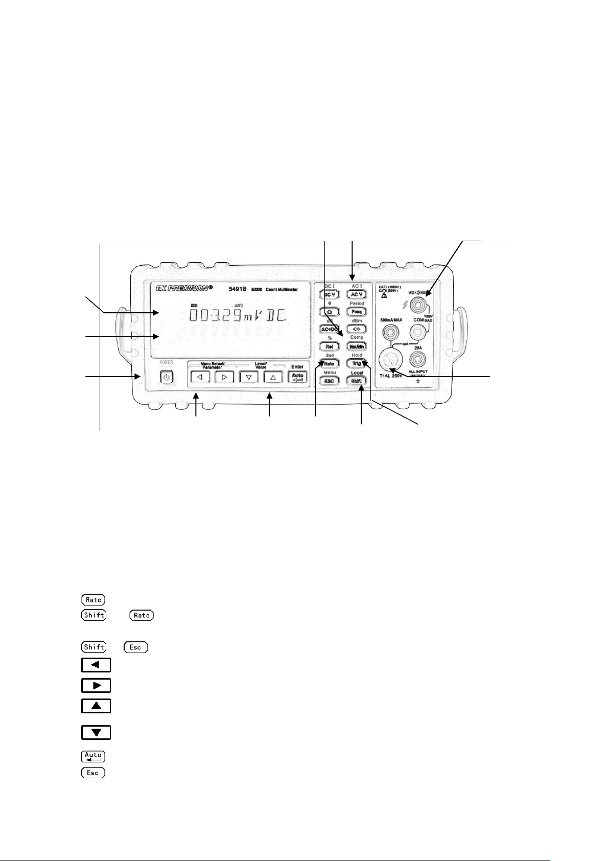
2.1 Front Panel Overview
The front panel of the multimeter is shown in Figure 2-1. This figure includes some important
abbreviated information that should be reviewed before operating the instrument.
Figure 2-1 Front Panel
1. Measurement Function keys (shifted and unshifted)
Select measurement function: DC voltage and current, AC voltage and current, resistance,
continuity, frequency, period, dB, dBm, True RMS AC+DC and diode test.
2. Math function keys
Select the math function: Rel, %, Max/Min, Comp and Hold.
nd
3. 2
4. Menu operation keys
Move through selections within menu level, command level or parameter level
Display and speed key
Changes reading rate: Fast, Medium and Slow.
→ turns on/ off the 2nd parameter display.
→ Open/Close menu
Move through selections within menu level, command level or parameter level.
Move up a level.
Move down a level.
(ENTER) Save the change made on “parameter” level, and return to the “command” level.
Cancel the change made on “parameter” level, and return to the “command” level.
9
Page 10
5. Range and Combination function selecting keys
Trig
Trig
Select a 2nd display parameter
Select a 2nd display parameter
Select a higher range and disable auto ranging.
Select a lower range and disable auto ranging.
Toggle between auto ranging and manual ranging.
6. Trig/Hold Key
Trigger a measurement from the front panel.
Hold a reading on the display.
7. Shift/Local keys
Used to access shifted keys.
(LOCAL) Cancel remote control mode and back to the LOCAL mode.
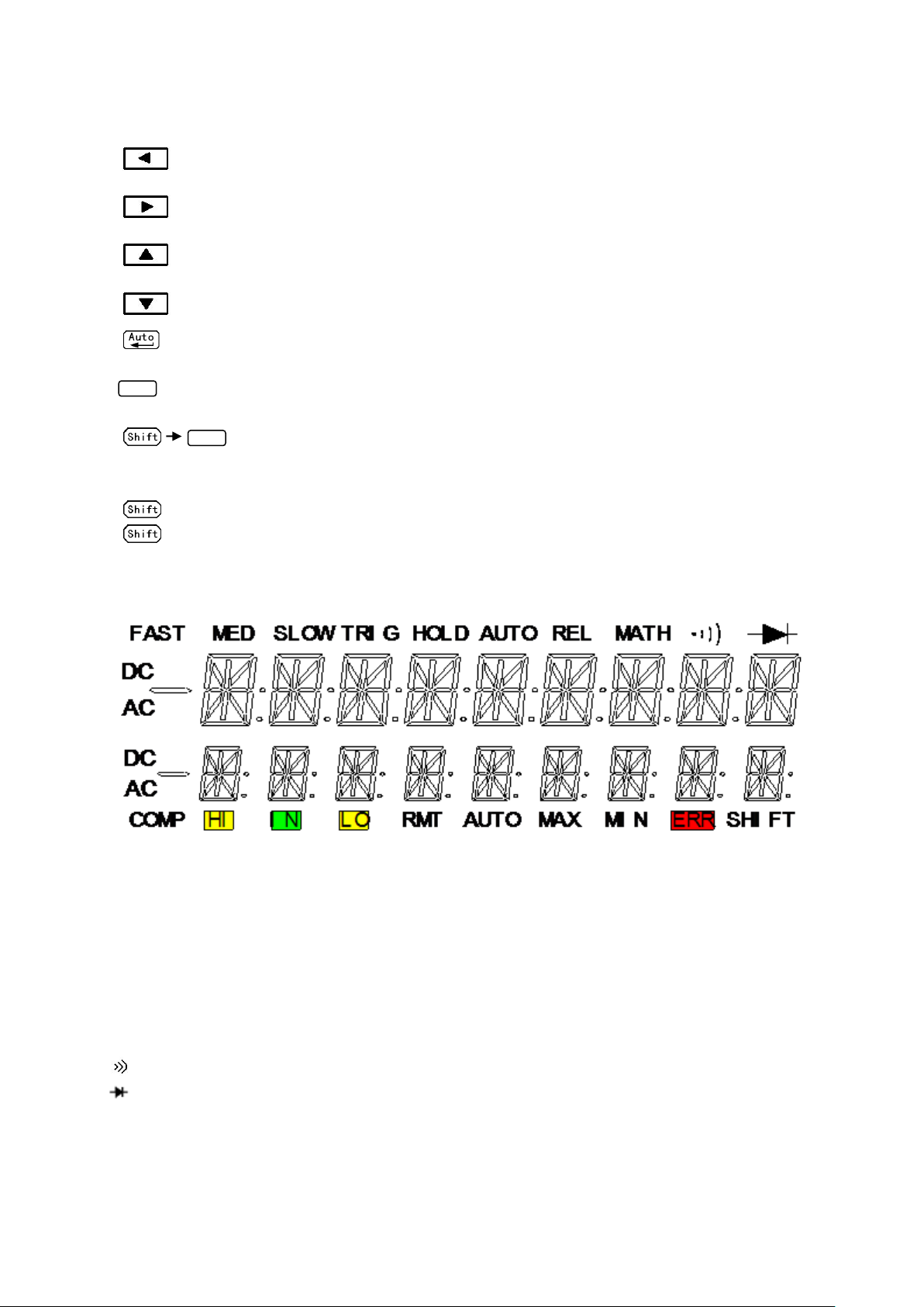
2.2 Annunciators on Screen
Figure 2-2 Display Annunciators
FAST Fast reading rate
MED Medium reading rate
SLOW Slow reading rate
TRIG Indicates trigger (front panel, bus) selected.
HOLD Reading HOLD function is enabled
REL Relative reading displayed
MATH A math operation is enabled (%, dB, dBm).
(Speaker) Beeper on for continuity testing function
(Diode) Instrument is in diode testing function
DC DC operation is enabled
AC AC operation is enabled
COMP Limit testing function is enabled
10
Page 11

HI/IN/LO Indicates the limit testing results
RMT Multimeter is in remote control mode
AUTO Auto ranging enabled
Max/Min MAX / MIN operation is enabled
ERR Hardware or remote control error detected
SHIFT Accessing shifted keys
2.3 Front Panel Menu Reference
A: MATH MENU
1: HI LIMIT → 2: LO LIMIT → 3: PERC REF → 4: dB REF→ 5: dBm REF
1. HI LIMIT Set the high limit for limit testing.
2. LO LIMIT Set the low limit for limit testing.
3. PERC REF Set the reference value for PERCENT function
4. dB REF Set the dB reference voltage value.
5. dBm REF Set the dBm reference impedance value.
B: TRIGGER MENU
1: TRIG MOD
1. TRIG MOD Select IMMediate, Manual or Bus trigger source mode.
C: SYSTEM MENU
1: BEEP STA → 2: BAUD RAT → 3: TX TERM → 4: RETURN → 5: KEY SONG → 6: REVISION
→ 7: ZERO CAL
1. BEEP STA Enable or disable the beeper function
2. BAUD RAT Select the baud rate for USB (virtual COM) or RS232 (Model 5491B only)
operation.
3. TX TERM Set the terminal character for USB (virtual COM) or RS232 (Model 5491B
only) operation, which identifies the end of a command string
4. RETURN Sets whether to enable Echo of the “sent” SCPI commands in return string.
(i.e. if ON, sending *IDN? will return with *IDN? and model information on
two separate lines).
5. KEY SONG Enable or disable the key sound when you press a key.
6. REVISION Shows the model number and firmware version of the instrument.
7. ZERO CAL Reserved for zeroing calibration of resistance measurement ranges.
11
Page 12
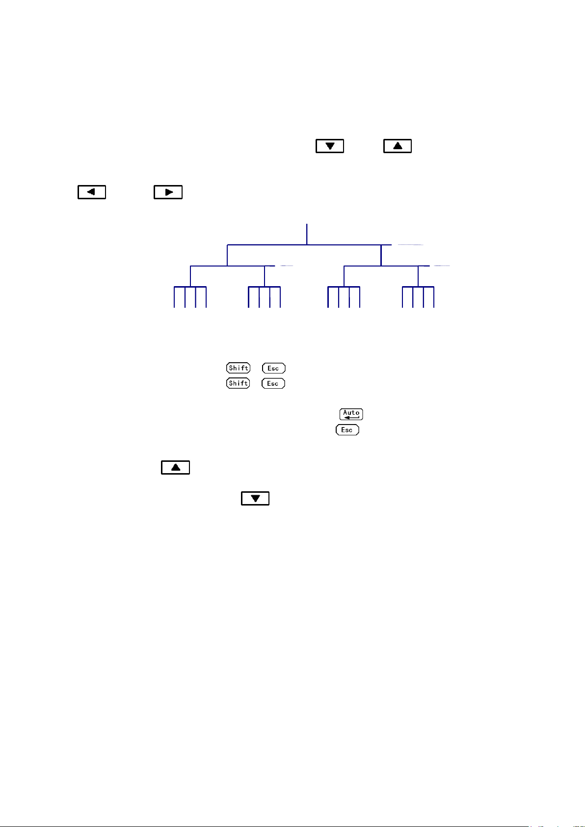
2.4 Front Panel Menu Overview
Menus
Commands
Parameters
The menu is organized in a top-down tree structure with three levels (menus, commands and
parameters) as shown in Figure 2-3. You can use down ( ) or up ( ) to move menu tree from
one level to another. Each of the three levels has several horizontal choices which you can view by using
left ( ) or right ( ).
Figure 2-3 Menu Tree
To turn on the menu, press → (Menu).
To turn off the menu, press → (Menu), or press any of the function or math keys on
the front panel.
To confirm a change on the “parameter” level, press (ENTER).
To cancel a change on the “parameter” level, press (Menu).
Note: If you press on the “menu” level, this is the top level of the menu and you cannot
go any higher; similarly if you press on the “parameter” level, this is the bottom level of
the menu and you cannot go any lower.
12
Page 13
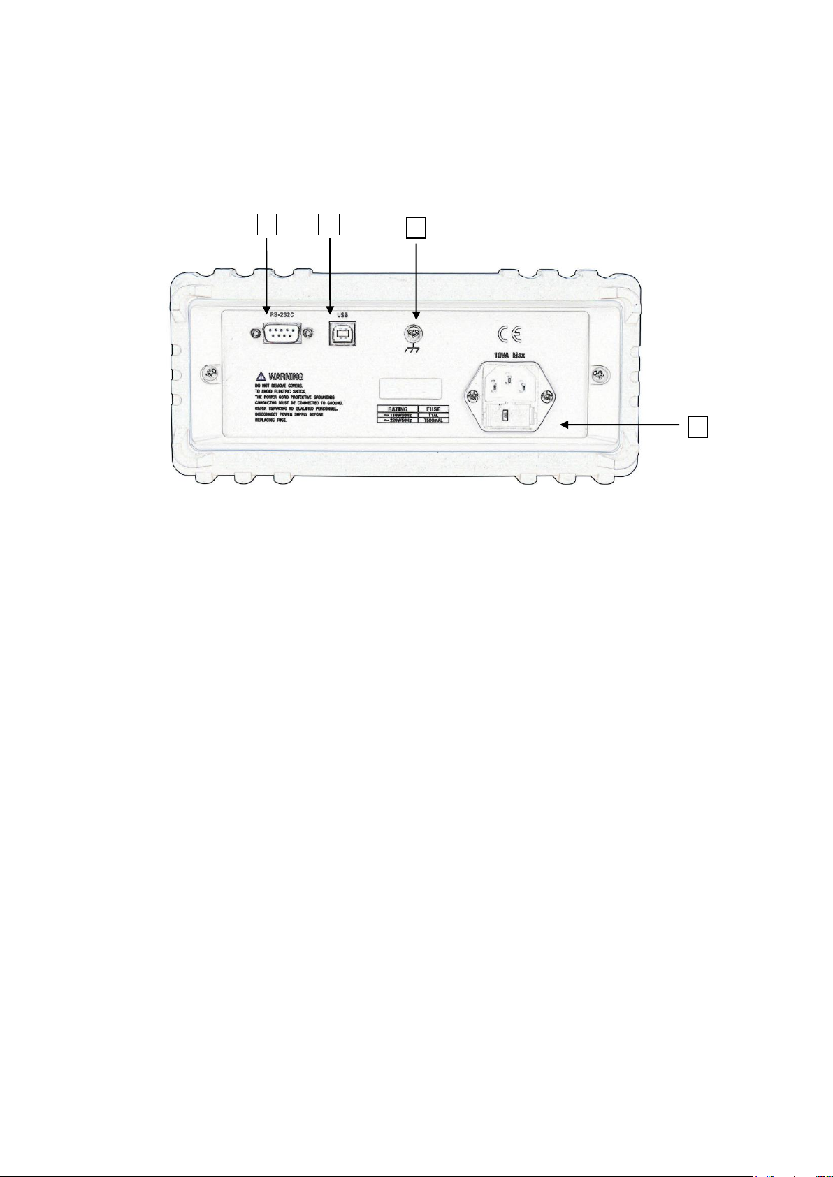
2.5 Rear Panel Summary
1
2 3 4
The rear panel of the multimeter is shown in Figure 2-4. This section includes important information that
should be reviewed before operating the instrument.
Figure 2-4 Rear Panel
1. USB Device Port
Connection port for USB remote control.
2. Grounding
Chassis Grounding terminal
3. Power-Line Fuse-Holder Assembly
The multimeter can be configured for line voltage of 110/220 V ± 10% AC at line frequency of 50/60
Hz ± 5%.
Power-line fuse is used for instrument protection. (220 V/500 mA or 110 V/1 A)
Note: Please use the same-type fuse. To verify and replace the fuse, remove the power
cable and pull out the fuse holder. To select between line voltage operations of 110 V
or 220 V, turn the grey colored fuse holder until the correct line voltage label is shown
on the outer window of the fuse holder. It should say “110” or “220” depending which
way you turn it.
4. RS232 Communication Port (Model 5491B only)
Connection port for remote control via RS232.
13
Page 14

2.6 Power up
2.6.1 Power Line Connection
Follow the procedure below to connect the multimeter to line power and turn on the instrument.
1. Check to make sure that the line voltage is in the correct range of 110 V or 220 V ± 10% (198 V to
242 V) and line frequency is in the range of 60 Hz or 50 Hz ± 5% (or 47.5 to 52.5 Hz) and that the
line voltage switch is in the correct position before connecting the power cord. To check, first look
at the label on the fuse compartment to verify if it is shown as “110” or “220”. If it is not switched to
the correct one, open up the fuse compartment and turn the grey fuse holder until it shows the
correct voltage label (110 or 220) on the outer part of the fuse compartment. Then, check to make
sure correct fuse value is used for the selected voltage operation.
CAUTION: Operating the instrument on an incorrect voltage may cause damage to the
instrument, possibly voiding the warranty.
2. Before plugging in the power cord, make sure that the front panel power switch is in the off position.
3. Connect the female end of the supplied power cord to the AC receptacle on the rear panel. Connect
the other end of the power cord to a grounded AC outlet.
WARNING: The power cord supplied with the multimeter contains a separate ground wire for use
with grounded outlets. When proper connections are made, instrument chassis is
connected to power line ground through the ground wire in the power cord. Failure to
use a grounded outlet may result in personal injury or death due to electric shock.
4. Turn on the instrument by pressing the front panel power switch and instrument is ready for
measuring.
2.6.2 Input Terminals
The input terminals are shown in Figure 2-5. The multimeter is protected against overloads up to the
limits as shown in table 2-1. Exceeding these limits may result in a hazard to both the multimeter and
operator.
14
Page 15
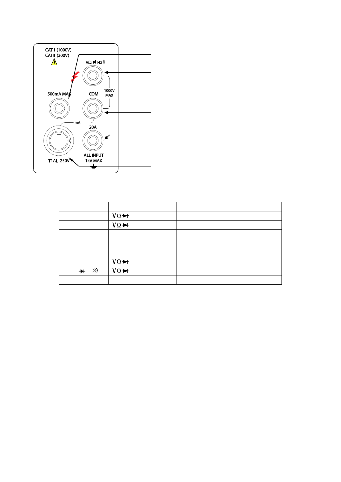
Function
Input Terminals
Maximum Allowable Input
DCV
to COM
1010V DC
ACV,HZ
to COM
757.5V AC RMS,1000V Peak
mA, HZ
500mA to COM
200mA (Model 5491B: 500 mA) DC
or AC RMS
20A,HZ
20A to COM
20A DC or AC RMS
Ω
to COM
500V DC or AC RMS
,
to COM
500V DC or AC RMS
All functions
Any terminals to earth
1000V DC or 1000V peak AC
Input-High terminal for Volts, ohms, Hz, period, diode and
continuity measurements
2 mA-200 mA for 2831E, 5 mA-500 mA for model 5491B
range DC/AC current input terminal for DC/AC current
Common terminal
2 A (5 A for model 5491B) and 20 A range current input
terminal for DC/AC current measurement
T1AL/250 V type fuse for the mA measurement range
Figure 2-5 Input terminals
Table 2-1 Input protection Limits
2.6.3 Power-up Sequence
On power-up, the multimeter performs self-tests on its EPROM and RAM and lights all segments and
annunciators for about 1 second. If a failure is detected, the instrument momentarily displays an error
message and the ERR annunciator turns on.
If the instrument passes self-tests, the firmware revision will be displayed momentarily.
2.6.4 High Energy Circuit Safety Precautions
To optimize safety when measuring voltage in high energy distribution circuits, read and use the
directions in the following.
When making measurements in high energy circuits, use test leads and accessories that meet the
following requirements:
Test leads and accessories must be fully insulated.
Only use test leads that can be connected to the circuit (e.g., alligator clips, spade lugs, etc.) for
15
Page 16

hands-off measurements.
Setting
Factory Default
Function
Range
Rate
Remote/Local
Trigger Mode
Relative Mode
Compare Mode
HI Limit
Lo Limit
Percent Mode
Reference
Max/Min Mode
Reading Hold
Secondary Display Mode
Cal Mode
DCV
AUTO
Medium
Local
Immediate
OFF
OFF
+1
-1
OFF
+1
OFF
OFF
OFF
OFF
Do not use test leads or accessories that decrease voltage spacing. This diminishes arc
protection and creates a hazardous condition.
Use the following sequence when measuring high energy circuits:
1. De-energize the circuit using a regular installed connect-disconnect device, such as a circuit
breaker, main switch, etc.
2. Attach the test leads to the circuit under test. Use appropriate safety rated test leads.
3. Set the multimeter to the proper measurement function and range.
4. Energize the circuit using the installed connect-disconnect device and make measurements
without disconnecting the multimeter.
5. De-energize the circuit using the installed connect-disconnect device.
6. Disconnect the test leads from the circuit under test.
WARNING: The maximum common-mode voltage (voltage between COM and the chassis
ground) is 500V peak. Exceeding this value may cause a breakdown in insulation,
creating a shock hazard.
2.6.5 Power-on Defaults
2831E and 5491B have a factory default setting for the power-on setting.
Since the basic measurement procedures in this manual assume the factory defaults, reset the
instrument to the factory settings when following step-by-step procedures. Table 2-2 lists the factory
default settings.
Table 2-2 Factory Default Settings
16
Page 17

2.6.6 Warm-up time
The multimeter is ready for use as soon as the power-up sequence has completed. However, to achieve
rated accuracy and stability, allow the instrument to warm up for half an hour. If the instrument has been
subjected to extreme temperatures, allow additional time for internal temperatures to stabilize.
2.7 Display
The display of the multimeter is primarily used to display readings, along with the units and type of
measurement. Annunciators located on the left, right and bottom indicate various states of operation.
See section 2.2 for a complete listing of annunciators.
17
Page 18
Chapter 3 Basic Measurements
ACV
DCV
ACV
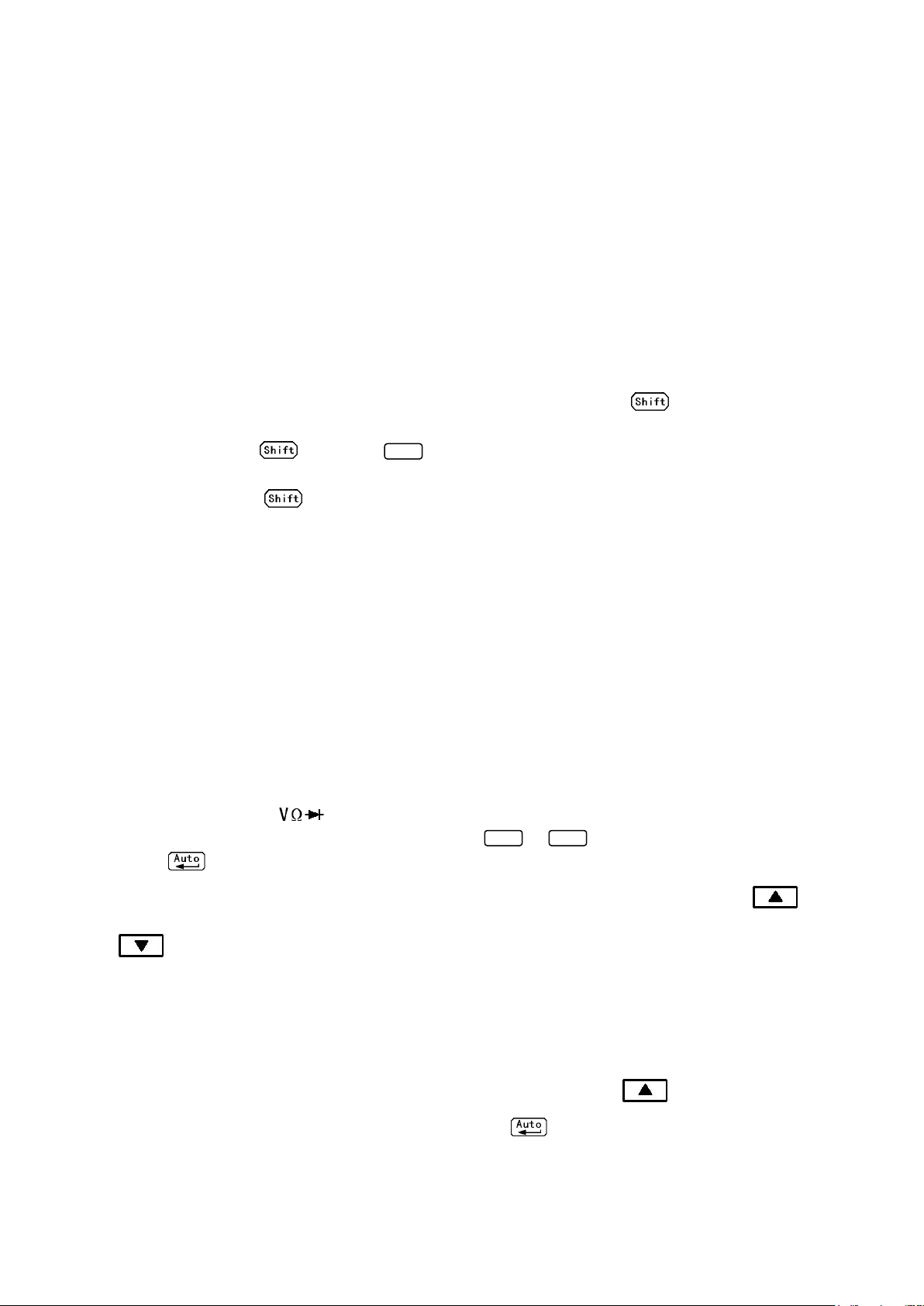
3.1 Preparation
One of the first things you would like to do with your multimeter is to become acquainted with its front
panel. We have provided some exercises in foregoing chapters about preparations for use and
operations of front panel.
The front panel has six rows of keys to select various functions and operations. Most keys have a shifted
function printed in blue above the key. To perform a shifted function, press (the Shift annunciator
will turn on). Then, press the key that has the desired label above it. For example, to select the AC
current function, press then press (ACI).
If you accidentally press , just press it again to turn off the Shift annunciator.
3.2 Measuring Voltage
Voltage ranges: 200 mV, 2 V, 20 V, 200 V, 1000 V (750 VAC) (model 5491B: 500 mV, 5 V, 50 V, 500 V,
1000 V (750 VAC))
Maximum resolution: 50 μV for DC and 1 mV for AC (on 200 mV range (model 2831E) and on 500 mV
range (model 5491B))
AC technique: true RMS, AC-coupled, 1000 V Peak AC
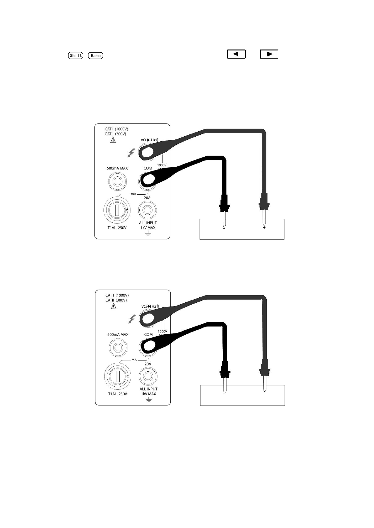
3.2.1 Connections
Assuming the multimeter is under factory default conditions, the basic procedure is as follows:
1. Connect test leads to and COM terminals.
2. Select DC or AC voltage measurement by pressing or .
3. Press to toggle between auto and manual ranging. Notice that the AUTO annunciator is
displayed when in auto ranging mode. If you want manual ranging, use the RANGE and
keys to select a measurement range consistent with expected voltage.
4. Connect test leads to the sources as shown in Figure 3-1.
CAUTION: Do not apply more than 1000V peak to the input or instrument damages may occur.
5. In manual range, if the “OVL.D” message is displayed, press the up key to select a higher
range until a desired reading is displayed (or press key for auto ranging). Use the lowest
possible range for the best resolution.
18
Page 19
6. Press + to turn on the secondary display, Use or key to choose the
AC VOLTAGE SOURCE
DC VOLTAGE SOURCE
function for secondary display.
7. Take readings from the display.
Input Resistance = 10 MΩ
CAUTION: Maximum Input = 1010 V peak
Input Impedance = 1.1 MΩ and 100 pF
CAUTION: Maximum Input = 750 V RMS or 1000 V peak, 3x10⁷ V-Hz
Figure 3-1 DC and AC Voltage Measurement Connections
19
Page 20

3.3 Measuring Current
DCV
ACV
Model 2831E current measurement range: 2 mA, 20 mA, 200 mA, *2 A, *20 A
Model 5491B current measurement range: 5 mA, 50 mA, 500 mA, *5 A, *20 A
*Indicates range is available for manual range only. Auto range will not work when reading requires
setting to this range.
Maximum resolution: 100nA (on 2 mA range (on 5 mA range for model 5491B))
Current measurement is available in Auto range for the lower current measurements only.
Note:
For 2831E, readings that are below 200 mA using the low current measurement input can be set in auto
range. This means it will auto range between 2 mA, 20 mA, and 200 mA range. For readings above
200 mA, auto range is not available. Manual range must be used to read any readings higher than 200
mA. This means, for ranges 2 A and 20 A, only manual range is available. Additionally, the high
current measurement input must be used to obtain measurements in these two higher ranges.
For 5491B, readings that are below 500 mA using the low current measurement input (fuse protected up
to 500 mA max.) can be set in auto range. This means it will auto range between 5 mA, 50 mA, and
500 mA range. For readings above 500 mA, auto range is not available. Manual range must be used
to read any readings higher than 500 mA. This means, for ranges 5 A and 20 A, only manual range is
available. Additionally, the high current measurement input must be used to obtain measurements in
these two higher ranges.
3.3.1 Connections
Assuming the multimeter is under factory default conditions, the basic procedure to measure current is
as follows (users must use manual range for measurement, following step 3):
1. Connect test leads between 500 mA terminal (for lower current measurements) and COM terminal or
between 20 A terminal (for higher current measurements) and COM terminal.
2. Select DCI or ACI measurement function by pressing → or → .
3. Press toggles auto ranging. Note that auto range is only available for readings that are
below 200 mA (for 2831E) and 500 mA (for 5491B) and when using the 500 mA max. terminal and
COM terminal connections. For readings above these limits, only manual range is available and
the 20 A terminal and COM terminal must be used to obtain measurement results. If instrument
shows the AUTO annunciator on display, press again to turn off auto ranging mode and go into
manual range mode. Use the RANGE and keys to select a measurement range
consistent with expected current.
4. Connect test leads to the source as shown in Figure 3-2.
CAUTION: Do not apply more than 1 A, 250 V to the 500 mA input terminal or the fuse will be
blown. Use 20 A terminal to measure current higher than 500 mA(or 200 mA for model 2831E).
20
Page 21
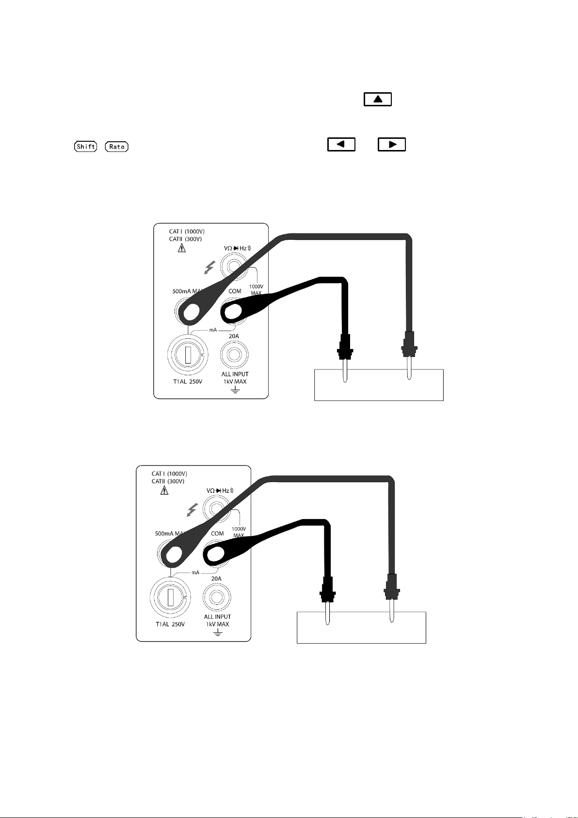
AC CURRENT SOURCE
DC CURRENT SOURCE
5. In manual range, if the “OVL.D” message is displayed, press up key to select a higher range
until a desired reading is displayed. Use the lowest possible range for the best resolution. Press
+ to turn on the 2nd parameter display, Use or key to select function for
2nd display.
6. Take readings from the display.
(Model 2831E) DC Current measurement on Range: 2 mA, 20 mA, 200 mA
(Model 5491B) DC Current measurement on Range: 5 mA, 50 mA, 500 mA
(Model 2831E) AC Current measurement on Range: 2 mA, 20 mA, 200 mA
(Model 5491B) AC Current measurement on Range: 5 mA, 50 mA, 500 mA
21
Page 22
AC CURRENT SOURCE
DC CURRENT SOURCE
(Model 2831E) DC Current measurement on Range: 2 A, 20 A
(Model 5491B) DC Current measurement on Range: 5 A, 20 A
(Model 2831E) AC Current measurement on Range: 2 A, 20 A
(Model 5491B) AC Current measurement on Range: 5 A, 20 A
CAUTION: Maximum Input = 20 A DC or RMS Maximum test times : < 20 s
Figure 3-2 DC and AC Current Measurements
3.3.2 Front Panel Fuse Replacement
WARNING: Make sure the instrument is disconnected from the power line and other equipment
1. Turn off the power and disconnect the power line and test leads.
before replacing the AMPS fuse.
22
Page 23
2. From the front panel, use a screwdriver to rotate the fuse carrier several turns counter-clockwise.
Take the fuse carrier out of the socket.
3. Remove the fuse and replace it with the same type (T1AL, 250V, 5×20mm).
CAUTION: Do not use a fuse with a higher current rating than specified or instrument may be
damaged. If the instrument repeatedly blows fuses, try to find out the reason before
replacing the fuse.
4. Install the new fuse by reversing the procedure above.
3.4 Measuring Resistance
Model 2831E Resistance measurement range: 200 Ω, 2 kΩ, 20 kΩ, 200 kΩ, 2 MΩ, 20 MΩ; Maximum
resolution: 10 mΩ (on 200 Ω range)
Model 5491B Resistance measurement range: 500 Ω, 5 kΩ, 50 kΩ, 500 kΩ, 5 MΩ, 50 MΩ; Maximum
resolution: 10 mΩ (on 500 Ω range)
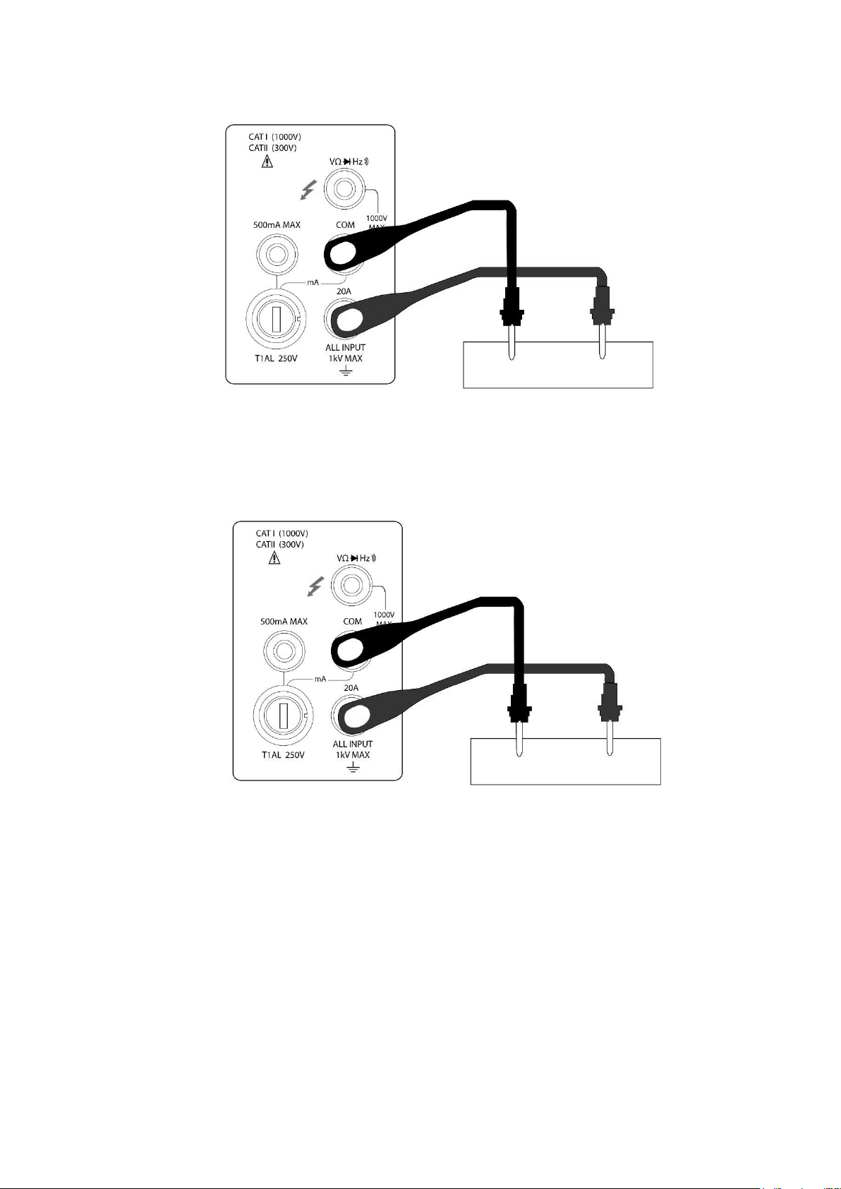
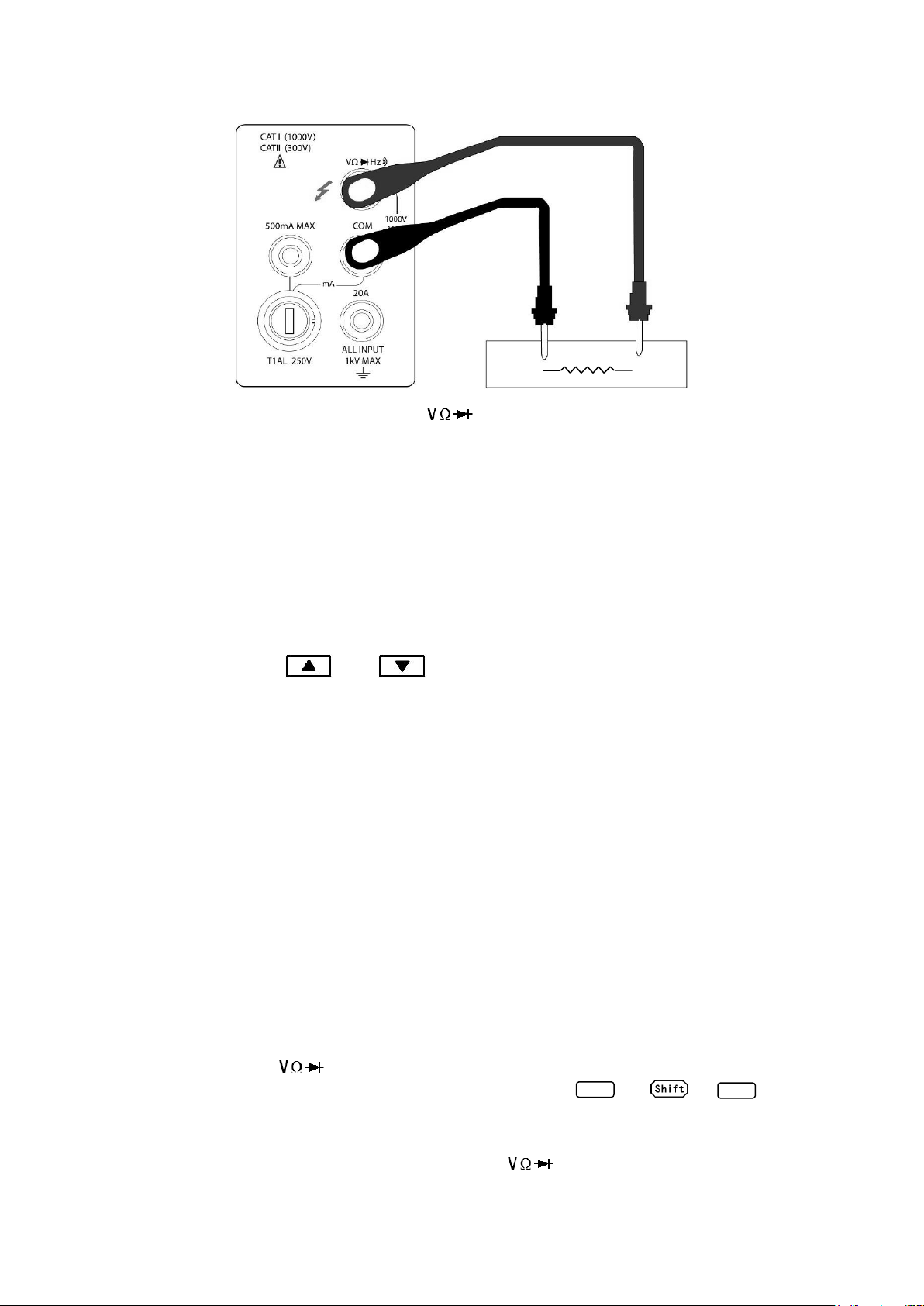
3.4.1 Connections
Assuming the multimeter is under factory default conditions, the basic procedure for measuring
resistance is as follows:
1. Connect the test leads between and COM.
2. Select resistance measurement function by pressing
3. Press toggles auto ranging. Notice the AUTO annunciator is displayed with auto ranging. If
you want manual ranging, use the RANGE and keys to select a measurement
range consistent with expected resistance.
4. Connect test leads to the resistance as shown in Figure 3-3:
CAUTION: Do not apply more than 1000 V peak between and COM or instrument
damage may occur.
5. In manual range, if the “OVL.D” message is displayed, press up key to select a higher range
until a normal reading is displayed (or press key for auto ranging). Use the lowest possible
range for the best resolution.
6. Take readings from the display.
23
Page 24
FREQ
FREQ
Note: Source current flows from the to COM terminals
Figure 3-3 Resistance Measurements
3.5 Measuring Frequency and Period
Frequency measurement range: 5 Hz to more than 1 MHz.
Period measurement range: 0.2 s to less than 1 μs.
Input signal range: 200 mV AC to 750V AC.
The instrument uses the volts input terminals to measure frequency. The AC voltage range can be
changed with the RANGE and keys. However, the signal voltage must be greater than
10% of the full-scale range.
3.5.1 Trigger Level and Measurement Errors
The multimeter uses a technique which maintains a constant resolution for any input frequency to
measure frequency and period. The gate time is always a multiple of the measured signal period rather
than a fixed time. The error will be no more than +/-1 from the total gate counts, which assures an
equivalent accuracy over the whole frequency range.
3.5.2 Gate Time
Gate time is the amount of time the meter uses to sample frequency or period readings. The
measurement speed rate and the measuring frequency change the gate time.
3.5.3 Connections
Assuming the multimeter is under factory default conditions, the basic procedure for measuring
frequency and period is as follows:
1. Connect test leads to and COM terminals.
2. Select frequency or period measurement functions by pressing or →
3. Connect test leads to the source as shown in Figure 3-4:
CAUTION: Do not exceed 1000 V peak between and COM, or instrument may be
24
Page 25

damaged.
Model 2831E
Measuring range
Beeper on
200.00 Ω
<10 Ω
2.0000 kΩ
<100 Ω
20.000 kΩ
<1 kΩ
200.00 kΩ
<10 kΩ
2.0000 MΩ
<100 kΩ
20.000 MΩ
<1 MΩ
Model 5491B
Measuring range
Beeper on
500.00 Ω
<10 Ω
5.0000 kΩ
<100 Ω
50.000 kΩ
<1 kΩ
500.00 kΩ
<10 kΩ
5.0000 MΩ
<100 kΩ
50.000 MΩ
<1 MΩ
AC VOLTAGE SOURCE
4. Take reading from the display
Figure 3-4 Frequency and Period Measurements
Input Impedance =1.1 MΩ in parallel with 100 pF
CAUTION: Maximum Input = 750 V RMS or 1000 V peak, 3x10⁷ V-Hz
3.6 Measuring Continuity
Under continuity test, when 200 Ω range is selected, the multimeter alerts you with a beep when a
reading is below a threshold resistance level of 10 Ω. For other ranges, the beeper will sound if a reading
is below a threshold resistance level listed in table 3-1. This beep will sound within less than half a
second when reading measured is below the threshold.
Table 3-1 Threshold resistance levels in Continuity Test
25
Page 26

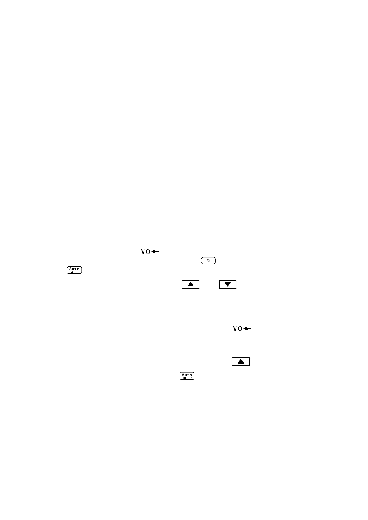
3.6.1 Connections
Assuming the multimeter is under factory default conditions, the basic procedure to measure continuity
is as follows:
1. Connect test leads to and COM terminals.
2. Select Continuity measurement function by pressing → .
3. Connect test leads to the resistance under test as shown in Figure 3-5.
4. Take reading from the display
Figure 3-5 Continuity Measurement
Note: Source current flows from the to COM terminals.
3.7 Testing Diode
The multimeter can also be used to measure the forward voltage drop of general-purpose diodes and
zener diodes. A current range of 0.5 mA will be selected for diode measurement.
Note: Diode test uses medium reading rate and is fixed.
3.7.1 Connections
Assuming the multimeter is under factory default conditions, the basic procedure to test a diode is as
follows:
1. Connect test leads to and COM terminals.
2. Press for diode measurement function.
3. Connect test leads to the diode under test as shown in Figure 3-6.
4. Take a reading from the display.
26
Page 27

22
)( acdcRMSDCAC
Diode
DCV
ACV
DCV
ACV
Figure 3-6 Diode Measurement
Note: Source current flows from the to COM terminals
3.8 Measuring True RMS AC+DC
The multimeter can measure the True RMS value of AC+DC voltages or currents (available in manual
range mode only).
When is pressed, the multimeter will measure the dc and ac signals respectively and then
calculate and display the AC+DC RMS value by using the following formula:
3.8.1 Connections
Assuming the multimeter is under factory default conditions, the basic procedure to measure true RMA
AC+DC is as follows:
1. Connect test leads to and COM terminals, as shown in Figure 3-7.
2. Press , , → or → to select a voltage or current
measurement
3. Press for true RMS measurement function.
4. Press + to turn on a 2nd display
5. Press or to select a 2nd parameter available.
6. Take a reading from the display.
27
Page 28

DC+AC RMS volt measurement
CURRENT SOURCE
VOLTAGE SOURCE
DC+AC RMS current measurement
Figure 3-7 True RMS value of AC+DC voltages and currents Measurement
3.8.2 Using the 2nd parameter display
The 2nd display is one of the most useful features designed in to the multimeter. Users may read two
different parameters at the same time.
The available 2nd display parameters under different main measurement functions are listed in Table 3-2.
28
Page 29

Primary Display
Secondary Display
DC V
AC V
dBm
dB
Hz AC V
DC V
dBm
dB
Hz DC V+AC V
dBm
dB
Hz
AC V
DC V
DC I
AC I
Hz
AC I
DC I
Hz
DC I+AC I
Hz
AC I
DC I
Hz
AC V/AC I
AC I/AC V
Percentage (%)
(Measuring value)
%
Comp
(Measuring value)
HI,IN,LO,PASS,FAIL
Max/Min
(Measuring value)
Max
Min
reference
referenceInput
Percent
Table 3-2 Available 2nd display parameters for different measurement functions
Note: When a 2nd parameter is displayed, the measurement range for that measurement is
based on the main measurement function (primary display).
3.9 Math Functions
The multimeter math operations are divided into three categories:
Percent
dB and dBm calculations
Limit testing
The first two categories are discussed here; reading limit testing will be described in the following
chapter – “Measurement Options”.
3.9.1 Percent
If the percent calculation is selected, a reference value must be specified. The displayed reading will be
expressed as percent deviation from the reference value. The percentage calculation is performed using
the following formula:
Where: Input is the normal display reading
Reference is the user-entered constant
Percent is the displayed result
To configure the percent calculation, perform the following steps:
29
Page 30

1. Press → for percent math operation and the present reference value displays:
REF
IN
V
V
dB log20
IN
V
REF
V
Rel
+1.00000
2. Use and keys to choose a numerical place and use and keys to
increment or decrement the digits. Enter a value and units prefix.
3. Press (ENTER) to confirm the reference value. The message “SAVED” will be displayed for a
moment.
4. The meter will then display the result of the percent calculation.
If you want to change the parameter values when the percent math function is enabled, besides the
above method you can do the following:
1. Press → to enter the menu. On the menu level, “A: MATH MEU” will be displayed.
2. Press to move down to the command level within the MATH MEU, “3: PERC REF” will be
displayed.
3. Press to enter the parameter level, and the present reference value will be displayed:
+1.00000 .
4. Use and keys to choose a numerical place and use and keys to
increment or decrement the digits. Enter a value and units prefix.
5. Press (ENTER) to confirm the reference value, “SAVED” will be displayed for a moment, and
the meter will return to the command level. Press to cancel the reference value input, and the
meter will return back to the command level without changing the reference value.
6. Press → key to exit the menu and return to the percent math operation status.
The meter will display measurement result based on calculation using the above formula. If the value of
“Input” is larger than that of “Reference”, displayed result will be positive; contrarily, it will be negative if
the value of “Input” is smaller than that of “Reference”.
3.9.2 dB Calculation
Expressing DC and AC voltage in dB makes it possible to compress a large range of measurements into
a much smaller scope. The relationship between dB and voltage is defined by the following equation:
Where:
is the DC or AC input signal.
is the specified voltage reference level
The instrument will read 0dB when the reference voltage level is applied to the input.
If a relative value is in effect when dB is selected, the value is converted to dB then REL is applied to dB.
If REL is applied after dB has been selected, dB has REL applied to it.
30
Page 31

mW
ZV
dBm
REFIN
1
)(
log10
2
IV
V
REF
Z
To set the reference voltage, perform the following steps:
1. Press + for dB math operation and the present reference value is displayed:
R.F:+0.00000
2. Use and keys to choose a numerical place and use and keys to
increment or decrement the digits. Enter a value and units prefix.
3. Press (ENTER) to confirm the reference voltage, the message “SAVED” will be displayed for
a moment. Then the meter will return back to the measurement status.
4. The display will now show result of the dB calculation.
If you want to change the parameter values when dB function is in effect, you can do the following:
1. Press → to enter the menu on the menu level, “A: MATH MEU” will be displayed.
2. Press to move down to the command level within the MATH MEU, “4: dB REF “will be
displayed.
3. Press to enter the parameter level, and the present reference value will be displayed:
R.F: +1.00000 .
4. Use and keys to choose a numerical place and use and keys to
increment or decrement the digits. Enter a value and units prefix.
5. Press (ENTER) to confirm the reference value, the message “SAVED” will be displayed for a
moment, and the meter will return to the command level. Press to cancel the reference value
input, and the meter will return back to the command level without changing the reference value.
6. Press → key to exit the menu and return to the dB math operation status.
Note: The dB calculation takes the absolute value of the ratio VIN/V
value of dB is -160 dB. This will accommodate a ratio of VIN = 1 µV, V
. The largest negative
REF
= 1000 V.
REF
3.9.3 dBm Calculation
dBm is defined as decibels above or below a 1 mW reference. With user-programmable reference
impedance, the meter reads 0 dBm when the voltage needed to dissipate 1 mW through the reference
impedance is applied. The relationship between dBm, reference impedance, and the voltage is defined
by the following equation:
Where:
is the DC or AC input signal.
is the specified reference impedance.
If a relative value is in effect when dBm is selected, the value is converted to dBm then REL is applied to
dBm. If REL is applied after dBm has been selected, dBm has REL applied to it.
31
Page 32

To set the reference impedance, perform the following steps:
1. Press → for dBm math operation and the present reference value is displayed:
REF:0000
2. Use and keys to choose a numerical place and use and keys to
increment or decrement the digits. Enter a value from 1 Ω to 9999 Ω.
3. Press (ENTER) to confirm the reference impedance, the message “SAVED” will be displayed
for a moment. The meter will then return back to the measurement status.
4. The display will show the result of the dBm calculation.
If you want to change the impedance reference value after the dBm function is enabled, you can do the
following:
1. Press → to enter the menu on the menu level. “A: MATH MEU” will be displayed.
2. Press to move down to the command level within the MATH MEU, “5: dBm REF” will be
displayed.
3. Press to enter the parameter level and the present impedance reference value will be
displayed: REF: 0000.
4. Use and keys to choose a numerical place and use and keys to
increment or decrement the digits. Enter a value from 1 Ω to 9999 Ω.
5. Press (ENTER) to confirm the reference value, the message “SAVED” will be displayed for a
moment, and the meter will return to the command level. Press to cancel the reference value
input, and the meter will return back to the command level without changing the reference value.
6. Press → key to exit the menu and return to the dB math operation status.
NOTE: The reference impedance and input impedance mentioned in this chapter are
completely different. The Input impedance is inherent to the instrument and cannot be
changed.
NOTE: dBm is valid for both positive and negative DC voltage.
NOTE: The percent math operations are applied after the dBm or dB math calculation.
32
Page 33

Chapter 4 Measurement Options
This chapter provides description of the front panel features of the multimeter. For those measurement
options accessible only by a remote interface, refer to Chapter 5 and 6. This chapter is organized as
follows:
Measurement Configuration – Describes Ranging, Relative readings, Digits of Resolution
and Measurement rate
Triggering operations – Explains trigger sources
MAX and MIN operations – Records the minimum and the maximum input signals
Limit operations – Defines how to set reading limits
System Operations – Provides details on Beep setup, Baud rate setup, Terminal character
setup and key sound setup up
4.1 Measurement configuration
The following paragraphs discuss configuring multimeter for making measurement.
4.1.1 Range
You can let the multimeter automatically select the range using auto ranging or you can select a fixed
range using manual ranging. Auto ranging is convenient because the multimeter automatically selects
the appropriate range for each measurement. However, you can use manual ranging for faster
measurements since the multimeter does not have to determine which range to use for each
measurement. The multimeter returns back to auto ranging when power has been off or after a remote
interface reset.
Maximum readings
The full scale readings for every range on each function are 5% over range except for the 1000 VDC,
750 VAC and diode test ranges.
Manual ranging
To select a range, simply press or key. The instrument changes one range per key
press. The selected range is displayed for a moment.
If the instrument displays the “OVL.D” message on a particular range, select a higher range until a
reading is displayed. Use the lowest range possible that can display a reading to ensure best accuracy
and resolution.
Auto ranging
To enable auto ranging, press key. The AUTO annunciator turns on when auto ranging is
selected. While auto ranging is selected, the instrument automatically chooses the best range to
33
Page 34

measure the applied signal. However, auto ranging should not be used when optimum speed is required.
Rel
Rel
Note that up-ranging and down-ranging occurs at 5% of normal range.
To cancel auto ranging, press or or key. Pressing to cancel auto ranging
leaves the instrument in its present manual range.
The key has no effect on the continuity and diode test functions.
4.1.2 Relative
The relative operation could be used to null offsets or subtract a baseline reading from present and
future readings. When relative function is enabled, the multimeter uses the present reading as a relative
value. Subsequent readings will be the difference between the actual input value and the relative value.
You can define a relative value for each function. Once a relative value is set for a measurement function,
the value is the same for all ranges. For example, if 2 V is set as a relative value on the 20 V range, the
relative is also 2 V on the 1000 V, 100 V, 1 V or 100 mV ranges. For model 5491B, if 2 V is set as
relative value on the 50 V range, the relative is also 2 V on the 1000 V, 500 V, 5 V or 500 mV ranges.
Additionally, when you perform a zero correction for DCV, Ω measurements by enabling REL, the
displayed offset becomes the reference value. Subtracting the offset from the actual input zeroes the
display, as follows:
Displayed reading = Actual Input – Reference
Select a range that cannot accommodate the relative value does not cause an overflow condition, but it
also does not increase the maximum allowable input for that range. For example: on the 2 V range,
model 2831E still overflows for a 2.1 V input. For model 5491B, on the 5 V range it will still overflow for
a 5.1 V input.
To set a REL value, press when the display shows the value you want as the relative value. The
REL annunciator turns on. Press a second time to disable REL.
4.1.3 Rate
The RATE operation sets the integration time of the A/D converter, the period of time the input signal is
measured. The integration time affects the usable digits, the amount of reading noise, as well as the
reading rate of the instrument.
In general, the fastest integration time (FAST set from the front panel or remote interface) results in
increased reading noise and fewer usable digits (resolution), while the slowest integration time provides
the best common-mode and normal-mode rejection and more usable digits. Depending on the selected
rate, user will have to compromise between speed or noise, as well as resolution.
34
Page 35

Trig
Trig
The RATE parameters are explained as follows:
Fast
FAST sets speed to 25 readings per second. Use FAST, if speed is of primary importance, however it is
at the expense of increased reading noise and fewer usable digits (resolution).
Medium
Medium sets speed to 10 readings per second. Use Medium to achieve a balance between noise
performance and speed.
Slow
Slow sets speed to 5 readings per second. SLOW provides better noise performance and resolution at
the expense of speed.
Note: The integration time can be set for any measurement function except frequency, period,
continuity (fixed at FAST rate) and diode test (fixed at Medium rate). For frequency and
period, this value is little excess a gate time.
4.2 Trigger Operations
The multimeter’s triggering system allows you to generate triggers either manually, automatically or
externally, and take multiple readings per trigger. The following paragraphs discuss front panel triggering,
and the reading hold feature.
4.2.1 Trigger procedure
Wait for Trigger
The control source holds up operation until the programmable event occurs and is detected. See
description below for trigger sources:
Immediate
With this trigger source, event detection is immediately satisfied allowing operation to continue.
External
Event detection is satisfied for both kinds of triggers as below:
1. A bus trigger (*TRG) command is received.
2. The front panel key is pressed (The multimeter must be taken out of remote
before it will respond to key).
Take steps below for trigger settings:
1. Press → to enter the menu on the menu level. “A: MATH MEU” will be displayed.
2. Use or key to move across to the TRIG MEU on the menu level. “B: TRIG MEU”
will be displayed.
3. Press to move down to the command level within the TRIG MEU.
35
Page 36

4. Use or key to move across to the TRIG MODE command on the command level.
Trig
Trig
“1: TRIG MOD” will be displayed.
5. Press to move down a level to select a trigger source.
6. Using or to select between IMM, MAN or BUS trigger source.
7. Press (ENTER) to confirm the selection. The message “SAVED” will be displayed to show
that the change is now in effect. The multimeter automatically exits the parameter level and moves
up a level to the command level.
4.2.2 Reading Hold
Reading hold function is used to hold a reading on the display indefinitely. To hold a reading, do the
following:
1. Press + to hold the reading on the display at any time. To un-hold the reading and
return to normal operation, press + again.
4.3 MAX / MIN
“MAX / MIN” function enables the multimeter to record the minimum and the maximum readings. If
“MAX / MIN” function is enabled, the 2nd parameter indicates the latest maximum or minimum reading.
Use the following procedure to turn on the MAX / MIN operation:
1. Press to enable the MAX / MIN function
2. Use or key to switch between MAX and MIN.
3. Press key again to disable the MAX/MIN function.
4.4 Limit Operations
Limit operations set and control the values that determine the HI / IN / LO status of subsequent
measurements. Limits can be applied to all measurement functions except continuity. Unit prefixes are
applied before the limit test, for example:
Low Limit = -1.0, High Limit = 1.0
A 150 mV reading equals 0.15 V (IN).
Low Limit = -1.0, High Limit = 1.0
A 0.6 kΩ reading equals 600 Ω (HI)
You can configure the multimeter to beep or not when readings are outside of the limit range.
36
Page 37

4.4.1 Enabling limits
Use the following procedure to turn on the limit operation:
1. Press → to enable or disable LIMIT TEST function.
4.4.2 Setting Limit Values
Use the following steps to enter high and low limit values:
1. Press → to enter the menu on the menu level.
2. Use or key to move across to the MATH MEU on the menu level, “A: MATH MEU”
will be displayed.
3. Press to move down to the command level within the MATH MEU.
4. Use or key to move across to the HIGH LIMIT command, “1: HI LIMIT” will be
displayed.
5. Press to move down a level to input the high limit value. The present high limit value will be
displayed:
HI: +1.00000
6. Use and keys to choose a numerical place and use and keys to
increment or decrement the digits. Enter an expected value for high limit.
7. Press (ENTER) to confirm the value of high limit. The message “SAVED” will be displayed to
show that the change is now in effect. The multimeter will exit the parameter level and move up a
level to the command level.
8. Use or key to move across to the LOW LIMIT command, “2: LO LIMIT” will be
displayed.
9. Press to move down a level to input the low limit value. The present low limit value will be
displayed:
LO: -1.00000
10. Use and keys to choose a numerical place and use and keys to
increment or decrement the digits. Enter an expected value for low limit.
11. Press (ENTER) to confirm the value of low limit. The message “SAVED” will be displayed to
show that the change is now in effect. The meter will exit the parameter level and move up a level to
the command level.
12. Press → key to exit from the menu and return to the measurement status.
4.5 System Operations
The multimeter has some other operations: Beeper control, key sound control, Baud rate control and
37
Page 38

Terminal character setup. The information is not directly related to making measurements but is an
important part of operating the multimeter.
4.5.1 Beeper Control
Normally, the multimeter will emit a tone whenever certain conditions are met. For example: the
multimeter will beep when a stable reading is captured in reading hold. You may want to disable the
beeper for certain applications.
When you disable the beeper, the multimeter will not emit a tone when:
1. A limit is exceeded in a limit test
2. A stable reading is captured in reading hold.
Disabling the beeper has no effect on the tone generated when:
1. An internal error is generated.
2. The continuity threshold is exceeded.
3. A front panel key is pressed.
The beeper state is stored in non-volatile memory and does not change when power has been off
or after a reset. The beeper is enabled when the multimeter is shipped from the factory.
Use the following steps to change the beeper’s state:
1. Press → to enter the menu on the menu level, “A: MATH MEU” will be displayed.
2. Use or key to move across to the SYS MEU on the menu level, “C: SYS MEU” will
be displayed.
3. Press to move down to the command level within the SYS MEU.
4. Use or key to move across to the BEEP command, “1: BEEP STA” will be
displayed.
5. Press to move down a level to set the beeper control.
6. Use or key to select ON or OFF.
7. Press (ENTER) to confirm the beeper control. The message “SAVED” will be displayed to
show that the change is now in effect. The multimeter will exit the parameter level and move up a
level to the command level.
8. Press → key to exit from the menu and return to the measurement status.
4.5.2 Baud rate
The baud rate is the rate at which the digital multimeter and the computer communicate. Choose one of
these available rates:
38.4k
19.2k
9600
4800
2400
38
Page 39

1200
600
Note: Factory default baud rate is 9600.
Before you choose a baud rate, make sure the programming terminal on a computer that will be used to
connect to the instrument supports the baud rate you selected. Both the digital multimeter and the
computer must be configured for the same baud rate.
Perform the following steps to select a baud rate
1. Press → to enter the menu on the menu level, “A: MATH MEU” will be displayed.
2. Use or key to move across to the SYS MEU on the menu level, “C: SYS MEU” will
be displayed.
3. Press to move down to the command level within the SYS MEU, “1: BEEP STR” will be
displayed.
4. Use or key to move across to the baud rate command, “2: BAUD RAT” will be
displayed.
5. Press to move down a level to set the baud rate.
6. Use or key to select a baud rate.
7. Press (ENTER) to confirm the selection. The message “SAVED” will be displayed to show
that the change is now in effect. The multimeter will exit the parameter level and move up a level to
the command level.
8. Press → key to exit from the menu and return to the measurement status.
4.5.3 Selecting the Terminal Character
The instrument has two kinds of terminal characters: <LF> (Line Feed) and <CR> (Carriage Return).
Perform the following steps to select the terminal characters:
1. Press → to enter the menu on the menu level, “A: MATH MEU” will be displayed.
2. Use or key to move across to the SYS MENU on the menu level, “C: SYS MEU”
will be displayed.
3. Press to move down to the command level within the SYS MEU, “1: BEEP STA” will be
displayed.
4. Use or key to move across to the terminal character command, “3: TX TERM” will
be displayed.
5. Press to move down a level to set the terminal character.
6. Use or key to select a terminal character.
39
Page 40

7. Press (ENTER) to confirm the selection. The message “SAVED” will be displayed to show
that the change is now in effect. The multimeter will exit the parameter level and move up a level to
the command level.
8. Press → key to exit from the menu and return to the measurement status.
4.5.4 Key Sound
The multimeter has a key sound function and you can enable or disable it. The key sound state is
stored in non-volatile memory and does not change when power has been off after a reset.
Note: Factory default key sound is enabled.
Use the following steps to change key sound setting:
1. Press → to enter the menu on the menu level, “A: MATH MEU” will be displayed.
2. Use or key to move across to the SYS MEU on the menu level, “C: SYS MEU” will
be displayed.
3. Press to move down to the command level within the SYS MEU, “1: BEEP STA” will be
displayed.
4. Use or key to move across to the KEY SONG command, “5: KEY SONG” will be
displayed.
5. Press to move down a level to enable or disable the key sound.
6. Use or key to turn ON or turn OFF the key sound.
7. Press (ENTER) to confirm the selection. The message “SAVED” will be displayed to show
that the change is now in effect. The multimeter will exit the parameter level and move up a level to
the command level.
8. Press → key to exit from the menu and return to the measurement status.
40
Page 41

Chapter 5 Remote Operation
Besides the front panel control, the multimeter provides a USB interface and RS232 interface (model
5491B only) for remote control. Standard Commands for Programmable Instruments (SCPI) is fully
supported to communicate with computer via the serial interface.
5.1 USB & RS232
You can connect the USB interface or RS232 interface (Model 5491B only) to a computer. To do so,
please note the following:
You must define the baud rate, parity, start bit, and stop bit (the USB interface is a virtual COM,
therefore it behaves like a RS232 serial port). Settings automatically will apply for RS232 port
also.
You must use the SCPI programming language
5.2 Serial Interface Operation
The instrument provides various remote commands. All operations from the front panel can be
performed by a computer via the USB interface.
5.2.1 USB interface configured as virtual COM RS232 interface
The USB interface in the rear panel of the instrument is a virtual COM port and behaves like a RS232
interface. This means that it can be connected to a USB port on a PC, and with the USB drivers
installed the PC will detect it as a serial COM port just like a RS232 serial port. In Windows, the PC will
automatically assign a COM port to the USB connection upon successful USB driver installation. Use
this COM port and configure the Baudrate, Parity, Start bit, and Stop bit settings as you would for RS232
communication. The settings will also apply to the RS232 port on model 5491B.
5.2.2 Sending and receiving data
The multimeter transfers data using 8 data bits, 1 stop bit, and no parity. Each program message that is
transmitted to the controller is terminated with <LF> or <CR>. Refer to section 4.5.3 for details on
configuring the termination character setting.
5.2.3 Selecting Baud Rate
The baud rate is the rate at which the multimeter and the computer communicate. Choose one of these
available rates:
38.4k
19.2k
9600
4800
2400
1200
41
Page 42

600
Note: Factory default baud rate is 9600.
Refer to section 4.5.2 for details on configuring baud rate settings on the multimeter.
5.2.4 Software Protocol
Please refer to the content below before programming application software.
1. For command syntax and format, refer to Chapter 6 Command Reference.
2. The controller transmits the command using the ASCII code with <LF> or <CR> as the termination
character. The multimeter executes the command after the termination character is received.
3. The character received by the multimeter will be sent back to the controller again. The controller will
not send the next character until the last returned character is received correctly from the meter. If
the controller fails to receive the character sent back from the meter, the possible reasons are listed
as follows:
The serial interface is not connected correctly.
Check if the same baud rate is selected for both the meter and the controller.
When the meter is busy with executing a bus command, it will not accept any character from
the serial interface at the same time. So the character sent by controller will be ignored. In order
to make sure the whole command is sent and received correctly, the character without a return
character should be sent again by the controller.
4. The multimeter only sends information under following two conditions. The first is when a character
is received normally; the meter will send the character back as a handshake. The second is when a
query command is received; the meter will send the query response information.
5. Once a query command is received, the meter will send the query response information
immediately even if the rest of the commands have not been finished. So if the command includes
two queries, the controller should read the query responses twice. One query is recommended to be
included in a single command.
6. A query response is sent out in ASCII codes with the preset termination character.
7. For some commands that will take longer time to execute, for example reset command, the
controller should keep waiting to avoid the next command being lost when the meter is executing
the former command.
5.3 Data Format
The meter outputs the measurement results using the ASCII character string format via the RS232 serial
interface. The data format is described in the following Figure 5-3.
SD.DDDDDDESDDD<NL>
S: +/ D: number 0 to 9
E: exponent sign (“+”is omitted)
<NL>: New Line, ASCII code is 10
Figure 5-3 Data Format
42
Page 43

Chapter 6 SCPI Command Reference
This chapter provides descriptions of all available remote communication commands which correspond
to Standard Commands for Programmable Instruments (SCPI) command sets. Use this chapter as a
reference.
6.1 Command structure
Commands are divided into two types: common commands and SCPI commands. The common
commands are defined in IEEE std. 488.2-1987, and these commands are common for all devices. Not
all commands are supported by the multimeter. The SCPI commands are used to control all of the
meter’s functions. They are tree structured with three levels of depth. (The highest level commands are
called the subsystem commands in this manual.) So the lower level commands are legal only when the
subsystem commands have been selected. A colon (:) is used to separate the higher level commands
and the lower level commands. See Figure 6-1 as an example.
SENSe
RESistance HOLD
RANGe STATe
SENS:RES:RANG 1k SENS:HOLD:STAT ON
AUTO
SENS:RES:RANG:AUTO ON
Figure 6-1 Command Tree Example
6.2 Command Syntax
The information in this section covers the syntax for both common commands and SCPI commands.
6.2.1 Commands and command parameters
Common commands and SCPI commands may or may not require specifying a parameter. The
following are some examples:
*RST No parameter used
:FORMat <name> Parameter<name> required
:IMMediate No parameter used
Commands that require a parameter input must have a space in between the command and the
parameter.
43
Page 44

Brackets [ ]: Some command words are enclosed in brackets. These brackets are used to denote
an optional command word that does not need to be included in the program message. For
example:
:RANGe[:UPPer] <n>
These brackets indicate that :UPPer is optional and does not have to be used. Thus, the above
command can be sent in one of the two ways below:
:RANGe <n>
or :RANGe:UPPer <n>
NOTICE: When using optional command words in your program, do not include the
brackets.
Angle brackets <>: Angle brackets are used to denote a parameter type. Do not include the
brackets in the program message. For example:
:HOLD:STATe <b>
The <b> indicates that a Boolean-type parameter is required. Thus, to enable the HOLD feature,
you must send the command with ON or 1 parameter as below:
:HOLD:STATe ON
or :HOLD:STATe 1
Parameter types: The following are some of the common parameter types:
<b> Boolean: Used to enable or disable an instrument operation. 0 or OFF disables the
operation and 1 or ON enables the operation. Example:
:CURRent:AC:RANGe:AUTO ON Enables auto ranging
<name> Name parameter: Select a parameter name from a listed group. Example:
<name> = MOVing
REPeat
:RESistance:AVERage:TCONtrol MOVing
<NRf> Numeric Representation format: This parameter is a number that can be expressed as
an integer (e.g., 6), a real number (e.g., 25.3) or an exponent (e.g., 5.6E2). Example:
:MMFactor 5
44
Page 45

<n> Numeric value: A numeric value parameter can consist of a NRf number or one of the
following name parameters: DEFault, MINimum, MAXimum. When DEFault
parameter is used, the instrument is programmed to the *RST default value. When
the MINimum parameter is used, the instrument is programmed to the lowest
allowable value. When the MAXimum parameter is used, the instrument is
programmed to the largest allowable value. Examples:
:CURRent[:DC]:NPLCycles 1
:CURRent[:DC]:NPLCycles DEFault
:CURRent[:DC]:NPLCycles MINimum
:CURRent[:DC]:NPLCycles MAXimum
6.2.2 Short-form Rules
Use the following rules to determine the short-form version of any SCPI command:
If the length of the command word is four letters or less, no short form version exists. Example:
:AUTO =:AUTO
These rules apply to command words that exceed four letters:
If the fourth letter of the command word is a vowel, delete it and all the letters after it. Example:
:immediate =:imm
Rule exception – The short form version of the following command uses only the first two letters of
the word.
:TCouple = :tc
If the fourth letter of the command word is a consonant, retain it but drop all the letters after it.
Example:
:format = :form
If the command contains a question mark (? for query) or a non-optional number included in the
command word, you must include it in the short-form version. Example:
:delay? = :del?
Command words or characters that are enclosed in brackets ([ ]) are optional and need not be
included in the program message.
6.2.3 Basic Rules of Command Structure
Letter case (upper and low) is ignored.
For example:
FUNC VOLT:DC = func volt:dc = Func Volt:Dc
Spaces (“_” is used to indicate a space) must not be placed before and/or after the colon (:).
For example:
(wrong) FUNC VOLT_:_DC
(right) FUNC VOLT:DC
The command can be completely spelled out or in abbreviated type. (In the following description,
short form will be printed in upper case.)
For example:
FUNCTION VOLTAGE:DC = FUNC VOLT:DC
45
Page 46

The command header should be followed by a question mark (?) to generate a query for that
command.
For example:
FUNC?
6.2.4 Multiple Command Rules
The semicolon (;) can be used as a separator to execute multiple commands on a single line. The
multiple command rules are as follows.
Commands at the same level and in the same subsystem command group can be separated by a
semicolon (;) on a multiple command line.
For example:
:RESistance:NPLCycle <n>;NPLCycles ?
To restart commands from the highest level, a semicolon (;) must be used as the separator, and
then a leading colon (:), which shows that the restarted command is a command at the top of the
command tree, must follow.
For example:
:RESistance:NPLCycle <n>; :RESistance:NPLCycles ?
The common commands can restart only after a semicolon on a multiple command line.
For example,
:RESistance:NPLCycles<n>;*IDN?
6.2.5 Command Path Rules
Each new program message must begin with the root command, unless it is optional (e.g.,
FUNCtion). If the root is optional, simply treat a command word on the next level as the root.
The colon at the beginning of a program message is optional and need not be used. Example:
:DISPlay:ENABle <b> = DISPlay:ENABle <b>
When the path pointer detects a colon(;), it moves down to the next command level.
When the path pointer detects a colon (:) after a semicolon (;), it resets back to the root level.
The path pointer can only move down. It cannot be moved up a level. Executing a command at a
higher level requires that you start over at the root command.
6.3 Command Reference
The multimeter provides the following subsystem commands:
◆ DISPlay ◆ FUNCtion ◆ VOLTage ◆ CURRent ◆ RESIstance ◆ FREQuency
◆ PERiod ◆ HOLD ◆ TRIGer ◆ FETCh ◆ SYSTem
The meter also supports following common commands:
◆ *RST ◆ *TRG ◆ *IDN
6.3.1 DISPlay subsystem
The DISPlay subsystem commands are mainly used to control the display of the multimeter and are
summarized in Table 6-2.
46
Page 47

Command
Function Description
:DISPlay
:ENABle <b>
:ENABle?
Enable or disable front panel display
Query state of the display
Table 6-1 DISPlay Subsystem Commands Summary
:ENABle <b>
Command syntax:
:DISPlay:ENABle <b>
Command Parameter:
<b> = 0 or OFF Disable front panel display
1 or ON Enable front panel display
Query:
:ENABle? Query state of the display
Description:
This command is used to enable or disable front panel display circuitry. When disabled, the
instrument operates at a higher speed. While disabled, the display is frozen. All front panel controls
except LOCAL are disabled. Normal display operation can be resumed by using:ENABle command
or pressing LOCAL key to enable the display.
47
Page 48

6.3.2 FUNCtion subsystem
Commands
Selectable Functions
:FUNCtion <name>
:FUNCtion?
Select measurement function: VOLTage:AC, VOLTage:DC,
RESistance, CURRent:AC, CURRent:DC, FREQuency, PERiod,
DIODe, CONTinuity.
Query Function
The commands in this subsystem are used to configure the measurement function subsystems and are
summarized in Table 6-2.
Table 6-2 FUNCtion Subsystem Commands Summary
:FUNCtion Command
:FUNCtion <name>
Command syntax:
:FUNCtion <name>
Command Parameter:
<name> = VOLTage:AC Select AC Voltage
VOLTage:DC Select DC Voltage
CURRent:AC Select AC Current
CURRent:DC Select DC Current
RESistance Select 2-wire Resistance
FREQuency Select Frequency
PERiod Select Period
DIODe Select Diode Testing
CONTinuity Select Continuity Testing
Query:
:FUNCtion? Query currently selected function
Description:
This command is used to select the measurement function of the instrument.
Each measurement function “remembers” its own unique setup configuration, such as range, speed,
filter and rel. This eliminates the need to re-program setup conditions every time you switch from
one function to another.
48
Page 49

6.3.3 VOLTage subsystem
Command
Function Description
Default
:VOLTage:DC
:NPLCycles <n>
:NPLCycles?
:RANGe
[:UPPer] <n>
[:UPPer]?
:AUTO <n>
:AUTO?
:REFerence <n>
:STATe <b>
:STATe?
:ACQuire
:REFerence?
Path to configure DC voltage
Set integration rate (*power line cycle: 0.1,1, or 10)
Query power line cycle integration rate
Path to configure measurement range
Select range (0 to 1000)
Query range
Enable or disable auto range
Query auto range (0 = OFF, 1 = ON)
Specify reference (-1010 to 1010)
Enable or disable reference
Query state of reference (0,1)
Use input signal as reference.
Query reference value (Note: Prior to using this
command, a reference must be enabled and reference
must be specified. Otherwise, an error may occur)
1
1000
ON
1
0
OFF
:VOLTage:AC
:NPLCycles <n>
:NPLCycles?
:RANGe
[:UPPer] <n>
[:UPPer]?
:AUTO <b>
:AUTO?
:REFerence <n>
:STATe <b>
:STATe?
:ACQuire
:REFerence?
Path to configure AC voltage
Set integration rate (*power line cycles: 0.1,1, or 10)
Query line cycle integration rate
Path to set measurement range
Select range (0 to 750)
Query range
Enable or disable auto range
Query auto range
specify reference (-757.5 to 757.5)
Enable or disable reference
Query state of reference
Use input signal as reference
Query reference value (Note: Prior to using this
command, a reference must be enabled and reference
must be specified. Otherwise, an error may occur)
1
750
ON
0
OFF
The commands in this subsystem are used to configure and control voltage measurement function and
are summarized in Table 6-3.
Table 6-3 VOLTage Subsystem Commands Summary
*Fast = 0.1, Medium = 1, Slow = 10
Speed Commands
: NPLCycles <n>
Command Syntax:
:VOLTage:AC:NPLCycles <n> Set NPLC for ACV
:VOLTage:DC:NPLCycles <n> Set NPLC for DCV
49
Page 50

Command Parameter:
<n> = 0.1, 1, 10 Set power line cycles per integration
DEFault 1
MINimum 10
MAXimum 0.1
Query:
:NPLCycles? Query programmed NPLC value
Description:
The integration period (measurement speed) for the basic measurement functions (except
Frequency and Period) is set using the:NPLCycles command. NPLC (Number of Power Line
Cycles) expresses the integration period based on the power line frequency. For example, for a PLC
of 1, the integration period in seconds would be 1/60 (for 60Hz line power) which is 16.67 ms.
:RANGe Commands
:[UPPer] <n>
Command syntax:
:VOLTage:AC:RANGe[:UPPer] <n> Set measurement range for ACV
:VOLTage:DC:RANGe[:UPPer] <n> Set measurement range for DCV
Command Parameter:
<n> = 0.2, 2, 20, 200, 750 Expected reading is AC volts (ACV)
0.2, 2, 20, 200, 1000 Expected reading is DC volts (DCV)
DEFault 750 (ACV)
1000 (DCV)
MINimum 0 (All functions)
MAXimum Same as DEFault
Query:
:RANGe[:UPPer]? Query measurement range of the current function.
Description:
This command is used to manually select the measurement range for the specified measurement
function. The range is selected by specifying the expected reading as an absolute value. Select the
appropriate range to get the optimal reading of the measured device.
:AUTO <b>
Command syntax:
:VOLTage:AC:RANGe:AUTO <b> Set auto range for ACV
:VOLTage:DC:RANGe:AUTO <b> Set auto range for DCV
Command parameter:
50
Page 51

<b> = 1 or ON Enable auto range
0 or OFF Disable auto range
Query:
:AUTO? Query auto range (ON or OFF)
Description:
These commands are used to control auto ranging. With auto ranging enabled, the instrument
automatically goes to the most ideal range to perform the measurement.
The auto range command (:RANGe:AUTO) is coupled to the command that manually selects the
measurement range (:RANGe <n>). When auto range is enabled, the parameter value for :RANGe
<n> changes to the automatically selected range value. Thus, when auto range is disabled, the
instrument remains at the automatically selected range. When a valid :RANGe <n> command is
sent, auto ranging disables.
:REFerence <n> Commands
:REFerence <n>
Command syntax:
:VOLTage:AC:REFerence <n> Specify reference for ACV
:VOLTage:DC:REFerence <n> Specify reference for DCV
Command parameter:
<n> = -757.5 to 757.5 Reference for ACV
-1010 to 1010 Reference for DCV
DEFault 0 (All measurement functions)
MINimum Minimum value for specified function
MAXimum Maximum value for specified function
Query:
:REFerence? Query reference for relative function
Description:
These commands are used to establish a reference value for the specified function. When reference
is enabled (:REFerence:STATe), the result will be the algebraic difference between the input signal
and the reference value:
Reading = Input signal – Reference
From the front panel, reference is called relative (REL).
The :REFerence <n> command is coupled to the :ACQuire command. The last command sent
(:REFerence <n> or :ACQuire) establishes the reference. When a reference is set using
the :REFerence <n> command, the REFerence? query command returns the programmed value.
Conversely, when a reference is set using the :ACQuire command, the :REFerence? query
command returns the acquired reference value.
(Note: In order to send a REFerence? query, the reference value must be set either
51
Page 52

by :REFerence <n> or :ACQuire command. If not, and error will occur in the return string.)
:STATe <b>
Command syntax:
:VOLTage:AC:REFerence:STATe <b> Control reference for ACV
:VOLTage:DC:REFerence:STATe <b> Control reference for DCV
Command parameter:
<b> = 1 or ON Enable reference
0 or OFF Disable reference
Query:
:STATe? Query state of reference.
Description:
These commands are used to enable or disable “reference” for the specified function. When
enabled, the displayed reading will include the programmed reference value. When disabled, the
displayed reading will not include the reference value.
:ACQuire
Command syntax:
:VOLTage:AC:REFerence:ACQuire Acquire reference for ACV
:VOLTage:DC:REFerence:ACQuire Acquire reference for DCV
Description:
When one of these commands is sent, the measurement input signal is acquired and established as
the reference value. This command is typically used to zero the display. For example, if the
instrument is displaying a 1 μV offset, sending this command and enabling reference zeroes the
display.
This command is functional only if the instrument is on the specified measurement function.
Sending this command while in any other function causes an error. Also, if the latest reading caused
an overflow condition or a reading has not been triggered, an error occurs when this command is
sent.
52
Page 53

6.3.4 CURRent subsystem
Command
Function Description
Default
:CURRent:DC
:NPLCycles <n>
:NPLCycles?
:RANGe
[:UPPer] <n>
[:UPPer]?
:AUTO <b>
:AUTO?
:REFerence <n>
:STATe <b>
:STATe?
:ACQuire
:REFerence?
Path to configure DC current
Set integration rate(*power line cycles: 0.1, 1, 10)
Query line cycle integration rate
Path to configure measurement range
Select range (0 to 20)
Query range
Enable or disable auto range
Query auto range
Specify reference (-20 to 20)
Enable or disable reference
Query state of reference
Use input signal as reference
Query reference value
1
20
ON
0
OFF
:CURRent:AC
:NPLCycles <n>
:NPLCycles?
:RANGe
[:UPPer] <n>
[:UPPer]?
:AUTO <b>
:AUTO?
:REFerence <n>
:STATe <b>
:STATe?
:ACQuire
:REFerence?
Path to configure AC voltage
Set integration rate (*power line cycles: 0.1, 1, 10)
Query line cycle integration rate
Path to set measurement range
Select range (0 to 20)
Query range
Enable or disable auto range
Query auto range
specify reference (0 to 20)
Enable or disable reference
Query state of reference
Use input signal as reference
Query reference value
1
20
ON
0
OFF
The commands in this subsystem are used to configure and control current measurement function and
are summarized in Table 6-4.
Table 6-4 CURRent Subsystem Commands Summary
*Fast = 0.1, Medium = 1, Slow = 10
Speed Commands
: NPLCycles <n>
Command Syntax:
: CURRent:AC:NPLCycles <n> Set NPLC for ACI
: CURRent:DC:NPLCycles <n> Set NPLC for DCI
53
Page 54

Command Parameter:
<n> = 0.1, 1, 10 Set power line cycles per integration
DEFault 1
MINimum 10
MAXimum 0.1
Query:
:NPLCycles? Query programmed NPLC value
Description:
The integration period (measurement speed) for the basic measurement functions (except
Frequency and Period) is set using the :NPLCycles command. NPLC (Number of Power Line
Cycles) expresses the integration period by basing it on the power line frequency. For example, for a
PLC of 1, the integration period in seconds would be 1/60 (for 60Hz line power) which is 16.67 ms.
:RANGe Commands
:[UPPer] <n>
Command syntax:
: CURRent:AC:RANGe[:UPPer] <n> Set measurement range for ACI
: CURRent:DC:RANGe[:UPPer] <n> Set measurement range for DCI
Command Parameter:
<n> = 0 to 20 Expected reading is AC volts (ACI)
-20 to 20 Expected reading is DC volts (DCI)
DEFault 20 (ACI, DCI)
MINimum 0 (All functions)
MAXimum Same as DEFault
Query:
:RANGe[:UPPer]? Query measurement range of the current function.
Description:
This command is used to manually select the measurement range for the specified measurement
function. The range is selected by specifying the expected reading as an absolute value. The
instrument will then go to the most sensitive range that will accommodate that expected reading. For
example, if you expect a reading of approximately 10 mA, simply let the parameter <n> = 0.01 (or
10e-3) in order to select the 20 mA range.
:AUTO <b>
Command syntax:
: CURRent:AC:RANGe:AUTO <b> Set auto range for ACI
: CURRent:DC:RANGe:AUTO <b> Set auto range for DCI
54
Page 55

Command parameter:
<b> = 1 or ON Enable auto range
0 or OFF Disable auto range
Query:
:AUTO? Query auto range (ON or OFF)
Description:
These commands are used to control auto ranging. With auto ranging enabled, the instrument
automatically goes to the most ideal range to perform the measurement.
The auto range command (:RANGe:AUTO) is coupled to the command that manually selects the
measurement range (:RANGe <n>). When auto range is enabled, the parameter value for:RANGe
<n> changes to the automatically selected range value. Thus, when auto range is disabled, the
instrument remains at the automatically selected range. When a valid :RANGe <n> command is
sent, auto ranging disables.
:REFerence <n> Commands
:REFerence <n>
Command syntax:
: CURRent:AC:REFerence <n> Specify reference for ACI
: CURRent:DC:REFerence <n> Specify reference for DCI
Command parameter:
<n> = -20 to 20 Reference for ACI
0 to 20 Reference for DCI
DEFault 0 (All measurement functions)
MINimum Minimum value for specified function
MAXimum Maximum value for specified function
Query:
:REFerence? Query reference for relative function
Description:
These commands are used to establish a reference value for the specified function. When reference
is enabled (:REFerence:STATe), the result will be the algebraic difference between the input signal
and the reference value:
Reading = Input signal – Reference
From the front panel, reference is called relative (REL).
The:REFerence <n> command is coupled to the :ACQuire command. The last command sent
(:REFerence <n> or :ACQuire) establishes the reference. When a reference is set using
the :REFerence <n> command, the REFerence? query command returns the programmed value.
55
Page 56

Conversely, when a reference is set using the :ACQuire command, the :REFerence? query
command returns the acquired reference value.
:STATe <b>
Command syntax:
: CURRent:AC:REFerence:STATe <b> Control reference for ACI
: CURRent:DC:REFerence:STATe <b> Control reference for DCI
Command parameter:
<b> = 1 or ON Enable reference
0 or OFF Disable reference
Query:
:STATe? Query state of reference.
Description:
These commands are used to enable or disable :reference” for the specified function. When
enabled, the displayed reading will include the programmed reference value. When disabled, the
displayed reading will not include the reference value.
:ACQuire
Command syntax:
: CURRent:AC:REFerence:ACQuire Acquire reference for ACI
: CURRent:DC:REFerence:ACQuire Acquire reference for DCI
Description:
When one of these commands is sent, the measurement input signal is acquired and established as
the reference value. This command is typically used to zero the display. For example, if the
instrument is displaying a 50 μA offset, sending this command and enabling reference zeroes the
display.
This command is functional only if the instrument is on the specified measurement function.
Sending this command while in any other function causes an error. Also, if the latest reading caused
an overflow condition or a reading has not been triggered, an error occurs when this command is
sent.
56
Page 57

6.3.5 RESistance subsystem
Command
Function Description
Default
:RESistance
:NPLCycles <n>
:NPLCycles?
:RANGe
[:UPPer] <n>
[:UPPer]?
:AUTO <b>
:AUTO?
:REFerence <n>
:STATe <b>
:STATe?
:ACQuire
:REFerence?
Path to configure resistance
Set integration rate (*power line cycles: 0.1, 1, 10)
Query line cycle integration rate
Path to configure measurement range
Select range (0 to 20e6)
Query range
Enable or disable auto range
Query auto range
Specify reference (0 to 20e6)
Enable or disable reference
Query state of reference
Use input signal as reference
Query reference value
1
20e6
ON
0
OFF
The commands in this subsystem are used to configure and control resistance measurement function
and are summarized in Table 6-5.
Table 6-5 RESistance Subsystem Commands Summary
*Fast = 0.1, Medium = 1, Slow = 10
Speed Commands
: NPLCycles <n>
Command System:
:RESistance:NPLCycles <n> Set NPLC for Ω
Command Parameter:
<n> = 0.1, 1, 10 Set power line cycles per integration
DEFault 1
MINimum 10
MAXimum 0.1
Query:
:NPLCycles? Query programmed NPLC value
Description:
The integration period (measurement speed) for the basic measurement functions (except
Frequency and Period) is set using the :NPLCycles command. NPLC (Number of Power Line
Cycles) expresses the integration period by basing it on the power line frequency. For example, for a
PLC of 1, the integration period in seconds would be 1/60 (for 60Hz line power) which is 16.67 ms.
57
Page 58

:RANGe Commands
:[UPPer] <n>
Command syntax:
:RESistance:RANGe[:UPPer] <n> Set measurement range for Ω
Command Parameter:
<n> = 0 to 20e6 Expected reading is ohms
DEFault 20e6 (Ω)
MINimum 0 (All functions)
MAXimum Same as DEFault
Query:
:RANGe[:UPPer]? Query measurement range of the current function.
Description:
This command is used to manually select the measurement range for the specified measurement
function. The range is selected by specifying the expected reading as an absolute value. The
instrument will then go to the most ideal range that will accommodate the expected reading. For
example, if you expect a reading of approximately 20 Ω, simply let the parameter <n> = 20 in order
to select the 200 Ω range (for model 2831E). If you expect a reading of approximately 50 Ω, simply
let the parameter <n> = 50 in order to select the 500 Ω range (for model 5491B).
:AUTO <b>
Command syntax:
:RESistance:RANGe:AUTO <b> Set auto range for Ω
Command parameter:
<b> = 1 or ON Enable auto range
0 or OFF Disable auto range
Query:
:AUTO? Query auto range (ON or OFF)
Description:
These commands are used to control auto ranging. With auto ranging enabled, the instrument
automatically goes to the most ideal range to perform the measurement.
The auto range command (:RANGe:AUTO) is coupled to the command that manually selects the
measurement range (:RANGe <n>). When auto range is enabled, the parameter value for :RANGe
<n> changes to the automatically selected range value. Thus, when auto range is disabled, the
instrument remains at the automatically selected range. When a valid :RANGe <n> command is
sent, auto ranging disables.
58
Page 59

:REFerence <n> Commands
:REFerence <n>
Command syntax:
:RESistance:REFerence <n> Specify reference for Ω
Command parameter:
<n> = 0 to 20e6 Reference for Ω
DEFault 0 (All measurement functions)
MINimum Minimum value for specified function
MAXimum Maximum value for specified function
Query:
:REFerence? Query reference for relative function
Description:
These commands are used to establish a reference value for the specified function. When reference
is enabled (:REFerence:STATe), the result will be the algebraic difference between the input signal
and the reference value:
Reading = Input signal – Reference
From the front panel, reference is called relative (REL).
The :REFerence <n> command is coupled to the :ACQuire command. The last command sent
(:REFerence <n> or :ACQuire) establishes the reference. When a reference is set using
the :REFerence <n> command, the REFerence? query command returns the programmed value.
Conversely, when a reference is set using the :ACQuire command, the :REFerence? query
command returns the acquired reference value.
:STATe <b>
Command syntax:
:RESistance:REFerence:STATe <b> Control reference for Ω
Command parameter:
<b> = 1 or ON Enable reference
0 or OFF Disable reference
Query:
:STATe? Query state of reference.
Description:
These commands are used to enable or disable “reference” for the specified function. When
enabled, the displayed reading will include the programmed reference value. When disabled, the
displayed reading will not include the reference value.
59
Page 60

:ACQuire
Command
Function Description
Default
:FREQuency
:THReshold
:VOLTage
:RANGe <n>
:RANGe?
:REFerence <n>
:STATe <b>
:STATe?
:ACQuire
:REFerence?
Path to configure frequency
Path to select the threshold voltage range:
Select threshold range (0 to 750).
Query threshold range
Specify reference (0 to 1.0e6)
Enable or disable reference
Query state of reference
Use input signal as reference
Query reference value
20
0
OFF
:PERiod
:THReshold
:VOLTage
:RANGe <n>
:RANGe?
:REFerence <n>
:STATe <b>
:STATe?
:ACQuire
:REFerence?
Path to configure period
Path to select the threshold voltage range:
Select threshold range (0 to 750).
Query threshold range
Specify reference
Enable or disable reference
Query state of reference
Use input signal as reference
Query reference value
20
0
OFF
Command syntax:
:RESistance:REFerence:ACQuire Acquire reference for Ω
Description:
When one of these commands is sent, the measurement input signal is acquired and established as
the reference value. This command is typically used to zero the display. For example, if the
instrument is displaying a 0.1 Ω offset, sending this command and enabling reference zeroes the
display.
This command is functional only if the instrument is on the specified measurement function.
Sending this command while in any other function causes an error. Also, if the latest reading caused
an overflow condition or a reading has not been triggered, an error occurs when this command is
sent.
6.3.6 FREQuency and PERiod subsystem
The commands in this subsystem are used to configure and control frequency as well as period
measurement function and are summarized in Table 6-6.
Table 6-6 FREQency and PERiod Subsystem Commands Summary
60
Page 61

:RANGe <n>
Command syntax:
:FREQuency:THReshold:VOLTage:RANGe <n> Set voltage threshold range.
:PERiod:THReshold:VOLTage:RANGe <n> Set voltage threshold range.
Command parameter:
<n> = 0 to 1010 Specify signal levels in volts (voltage threshold)
Query:
:RANGe? Query maximum signal level.
Description:
These commands are used to specify the expected input level. The instrument will then
automatically select the most ideal current or voltage threshold range.
:REFerence <n> Commands
:REFerence <n>
Command syntax:
:FREQuency:REFerence <n> Specify reference for FREQ
:PERiod:REFerence <n> Specify reference for PER
Command parameter:
<n> =
0 to 1.0e6 Reference for FREQ
0 to 1 Reference for PER
DEFault 0 (All measurement functions)
MINimum Minimum value for specified function
MAXimum Maximum value for specified function
Query:
:REFerence? Query reference for relative function
Description:
These commands are used to establish a reference value for the specified function. When reference
is enabled (:REFerence:STATe), the result will be the algebraic difference between the input signal
and the reference value:
Reading = Input signal – Reference
From the front panel, reference is called relative (REL).
The :REFerence <n> command is coupled to the :ACQuire command. The last command sent
(:REFerence <n> or :ACQuire) establishes the reference. When a reference is set using
the :REFerence <n> command, the REFerence? query command returns the programmed value.
Conversely, when a reference is set using the :ACQuire command, the :REFerence? query
command returns the acquired reference value.
61
Page 62

:STATe <b>
Command syntax:
:FREQuency:REFerence:STATe <b> Control reference for FREQ
:PERiod:REFerence:STATe <b> Control reference for PER
Command parameter:
<b> = 1 or ON Enable reference
0 or OFF Disable reference
Query:
:STATe? Query state of reference.
Description:
These commands are used to enable or disable “reference” for the specified function. When
enabled, the displayed reading will include the programmed reference value. When disabled, the
displayed reading will not include the reference value.
:ACQuire
Command syntax:
:FREQuency:REFerence:ACQuire Acquire reference for FREQ
:PERiod:REFerence:ACQuire Acquire reference for PER
Description:
When one of these commands is sent, the measurement input signal is acquired and established as
the reference value. This command is typically used to zero the display. For example, if the
instrument is displaying a 10 Hz offset, sending this command and enabling reference zeroes the
display.
This command is functional only if the instrument is on the specified measurement function.
Sending this command while in any other function causes an error. Also, if the latest reading caused
an overflow condition or a reading has not been triggered, an error occurs when this command is
sent.
6.3.7 TRIGger subsystem
These commands in this subsystem are used to configure and control trigger measurement function and
are summarized in Table 6-8.
62
Page 63

Table 6-8 TRIGger Subsystem Commands Summary
Command
Function Description
Default
:TRIGger
:SOURce <name>
:SOURce?
Select control source
Query control source
IMMediate
Trig
:TRIGger
TRIGger subsystem commands are used for the instrument settings of trigger mode, trigger delay and
triggering a measurement.
:SOURce <name>
Command Syntax:
TRIGger:SOURce <name>
Command parameter:
<name> = IMMediate instrument default setting is internal trigger
BUS Triggered via USB/RS232 interface
MANual (EXTernal) (Press in the front panel for Trigger)
Query:
:SOURce? Query control source
Description:
These are used to select the event control source.
6.3.8 FETCH Subsystem
FETCh? Command
Command syntax:
:FETCh?
Description:
This query command is used to obtain the last available reading. This command does not affect the
configuration of the instrument.
This command does not trigger a measurement. The command simply requests the last available
reading. It will continue to return the same last reading until there is a new reading.
This command will be automatically asserted when :READ? or :MEASure? command is sent.
63
Page 64

6.3.9 SYSTem Subsystem
SYSTem:ERRor Command
Command syntax:
:SYSTem:ERRor?
Description:
This query command is used to query error messages from the error queue. From front display, if
a wrong command has been sent, the display will show an error message for approximately one
second. That error can be queried from the error queue by sending this command.
Error Messages:
“NO ERROR!” – This means no error(s) have occurred.
“BUS:BAD COMMAND.” – This means either a wrong command was sent to the instrument or there may
be misspelling in the command.
6.3.10 Common Commands
Common commands can be used to all equipment. We provide some common commands as shown
below:
*RST
Command Syntax:
*RST
Description:
Reset the instrument
*TRG
Command Syntax:
*TRG
Description:
Trigger the instrument for measurement
*IDN?
Query Syntax:
*IDN?
Query return:
<product>,<version><LF^END>
Here:
<product> 2831E Multimeter
<version> Ver1.0.09.12.03
Description: Query information of the instrument
64
Page 65

Chapter 7 Specifications
Measurement Function
Slow
Med
Fast
DCV 5 10
25
DCA 5 10
25
ACV 5 10
25
ACA 5 10
25
Ω (Ranges below 2M )
5
10
25
Ω (20M range and above)
1.3
2.6
5.6
Freq/ Period
1 2 3.9
Using dual display
0.9
0.9
0.8
True RMS DC+AC
1.2
1.4
1.5
Diode
————
10
————
Continuity
————
————
25
A-1 Introduction
Chapter 7 describes the complete specifications of the multimeter.
A-2 Technical Specifications
Specifications are based on the following conditions:
One year calibration cycle.
Operating temperature at 18 °C to 28 °C
Accuracy is expressed as: ± (% of reading + % of range) after 30 minutes warm-up.
Temperature Coefficient: add ± [0.1% × (the applicable accuracy)/°C] for 0 °C to 18 °C and
28 °C to 40 °C
Relative Humidity: Up to 80% RH for 0 °C to 28 °C (75% RH for 10 MΩ and above ranges
for resistance measurement). Up to 70% RH for 28 °C to 40 °C
Displayed Readings and Reading rates
Reading rates on front panel (approximate reading/sec)
65
Page 66

MODEL 2831E SPECIFICATIONS
Rate
Range
Resolution
Full Scale
Reading
Accuracy
(1 year)
Typical
Input
Impedance
Slow
200.00 mV
2.0000 V
20.000 V
200.00 V
1000.0 V
10 μV
100 μV
1 mV
10 mV
100 mV
210.00
2.1000
21.000
210.00
1010.0
(2)
0.03%+0.08%
(1)
0.03%+0.05%
(1)
0.03%+0.06%
0.03%+0.06%
0.03%+0.06%
>10 MΩ
>11.1 MΩ
>10.1 MΩ
10 MΩ
10 MΩ
(1)
under REL status
(2)
1% over-range (1010 V) is readable at 1000 V range
Range
Resolution
Full Scale Reading
200.00 mV
2.0000 V
20.000 V
200.00 V
750.0 V
10 μV
100 μV
1 mV
10 mV
100 mV
210.00
2.1000
21.000
210.00
757.5
(1)
(1)
1% over-range (757.50V) is readable at 750V range
Rate
Range
Accuracy(1 year)
(1)
23 °C ± 5 °C
20-50 Hz
50-20 kHz
20-50 kHz
50-100 kHz
Slow
200.00 mV
2.0000 V
20.000 V
200.00 V
750.0 V
1.0%+0.2%
1.0%+0.2%
1.0%+0.2%
------
------
0.5%+0.15%
0.4%+0.05%
0.4%+0.05%
0.8%+0.075%
0.8%+0.075%
1.8%+0.25%
1.5%+0.1%
1.5%+0.1%
1.5%+0.1%
1.5%+0.1%
(2)
3.0%+0.75%
3.0%+0.25%
3.0%+0.25%
3.0%+0.25%
3.0%+0.25%
(2)
(1)
Specifications are for sine wave inputs >5% of range.
(2)
Limit at 40 kHz or ≤ 3×10⁷ Volt-Hz for 750 V range
DC Voltage
Resolution, Full Scale reading and Accuracy: ± (% of reading + % of range), 23 °C ± 5 °C
Maximum input voltage: 1000 VDC or peak ac for all ranges.
AC Voltage
Resolution, Full Scale reading and Accuracy
ACCURACY: ± (% of reading + % of range), 23 °C ± 5 °C
Measurement method: True RMS measurement
Maximum Crest factor: 3.0 at full scale
Maximum input voltage: 750 Vrms
≤ 3×10⁷ Volt-Hz for all ranges
Input impedance: 1 MΩ ± 2% in parallel with capacitance <100 pF
Maximum DCV: 500 V for all AC ranges
66
Page 67

DC Current: ± (% of reading + % of range), 23 °C ± 5 °C
Rate
Range
Resolution
Full Scale
Reading
Accuracy
(1 year)
Burden Voltage
(1)
& Shunt Resistor
Slow
2.0000 mA
20.000 mA
200.00 mA
2.0000 A
20.000 A
0.1 μA
1 μA
10 μA
100 μA
1 mA
2.1000
21.000
210.00
2.1000
21.000
(3)
0.08%+0.025%
(2)
0.08%+0.02%
(2)
0.08%+0.02%
0.3%+0.025%
0.3%+0.025%
<0.3 V / 100 Ω
<0.04 V / 1 Ω
<0.3 V / 1 Ω
<0.05 V / 10 mΩ
<0.6 V / 10 mΩ
(1)
Typical voltage across the input terminals at full scale reading.
(2)
Use REL function
(3)
In 20 A range, >10-20 ADC is readable for 20 seconds maximum
Rate
Range
Accuracy(1 year)
(1)
23 °C ± 5 °C
20-50 Hz
50-2 kHz
2-20 kHz
Slow
2.0000 mA
20.000 mA
200.00 m A
2.0000 A
20.000 A
1.5%+0.5%
1.5%+0.5%
1.5%+0.5%
2.0%+0.5%
2.0%+0.5%
0.5%+0.3%
0.5%+0.3%
0.5%+0.3%
0.5%+0.5%
0.5%+0.5%
2%+0.5%
2%+0.38%
2%+0.38%
------
------
(1)
Specifications are for sine wave inputs >5% of range.
Rate
Range
Resolution
Full Scale
Reading
Burden Voltage
(1)
/shunt Resistor
Slow
2.0000 mA
20.000 mA
200.00 m A
2.0000 A
20.000 A
0.1 μA
10 μA
100 μA
1 mA
10 mA
2.1000
21.000
210.00
2.1000
21.000
(2)
<0.3 V / 100 Ω
<0.04 V / 1 Ω
<0.3 V / 1 Ω
<0.05 V / 10 mΩ
<0.6 V / 10 mΩ
(1)
Typical voltage across the input terminals at full scale reading.
(2)
In 20 A range,>10-20 A AC is readable for 20 seconds maximum
Maximum Input and Overload Current Protection: 1 A/ 250 V fuse.
AC Current (True RMS, AC Coupling)
ACCURACY: ± (% of reading + % of range), 23 °C ± 5 °C
Measurement method: True RMS measurement
Maximum Crest factor: 3.0 at full scale
Maximum Input and Overload Current Protection: 1 A/ 250 V fuse.
67
Page 68

Resistance: ± (% of reading + % of range), 23 °C ± 5 °C
Rate
Range
(1)
Resolution
Full Scale
Reading
Test Current
Accuracy
(1 year)
Slow
200.00 Ω
2.0000 kΩ
20.000 kΩ
200.00 kΩ
2.0000 MΩ
20.000 MΩ
10 mΩ
100 mΩ
1 Ω
10 Ω
100 Ω
1 kΩ
210.00
2.1000
21.000
210.00
2.1000
21.000
0.5 mA
0.45 mA
45 μA
4.5 μA
450 nA
45 nA
0.10%+0.05%
(2)
0.10%+0.025%
(2)
0.10%+0.025%
(2)
0.10%+0.025%
0.15%+0.025%
0.3%+0.05%
(1)
In order to eliminate the noise interference, which might be induced to the test leads, it is
recommended to use a shielded test cable for measuring resistance above 100 kΩ.
(2)
Using REL function
Range
Resolution
Full Scale
Reading
Test Current
Accuracy (1 year)
23 °C ± 5 °C
200 Ω
100 mΩ
999.9
0.5 mA
0.1%+0.1%
Rate
Range
Resolution
Full Scale
Reading
Accuracy
(1 year)
Typical
Input
Impedance
Slow
500.00 mV
5.0000 V
50.000 V
500.00 V
1000.0 V
10 μV
100 μV
1 mV
10 mV
100 mV
510.00
5.1000
51.000
510.00
1010.0
(2)
0.02%+0.016%
(1)
0.02%+0.008%
(1)
0.02%+0.008%
0.02%+0.008%
0.02%+0.008%
>10 MΩ
>11.1 MΩ
>10.1 MΩ
10 MΩ
10 MΩ
(1)
under REL status
(2)
1% over-range (1010 V) is readable at 1000 V range
Maximum Input Protection: 1000 VDC or 750 VAC for all ranges.
Open circuit voltage: Maximum voltage is 5.5 V dc
Continuity: ± (% of reading + % of range), 23 °C ± 5 °C
Maximum Input Protection: 1000 VDC or 750 VAC for all ranges.
Open circuit voltage: < 5.5 V DC
Test Current: around 0.5 mA DC
Threshold value: 5% of range
MODEL 5491B SPECIFICATIONS
DC Voltage
Resolution, Full Scale reading and Accuracy: ± (% of reading + % of range), 23 °C ± 5 °C
Maximum input voltage: 1000 VDC or peak ac for all ranges.
68
Page 69

AC Voltage
Range
Resolution
Full Scale Reading
500.00 mV
5.0000 V
50.000 V
500.00 V
750.0 V
10 μV
100 μV
1 mV
10 mV
100 mV
510.00
5.1000
51.000
510.00
757.5
(1)
(1)
1% over-range (757.50 V) is readable at 750 V range
Rate
Range
Accuracy(1 year)
(1)
23 °C ± 5 °C
20-50 Hz
50-20 kHz
20-50 kHz
50-100 kHz
Slow
500.00 mV
5.0000 V
50.000 V
500.00 V
750.0 V
1.0%+0.08%
1.0%+0.08%
1.0%+0.08%
------
------
0.5%+0.06%
0.35%+0.02%
0.35%+0.02%
0.5%+0.03%
0.5%+0.03%
1.5%+0.1%
1%+0.04%
1%+0.04%
1%+0.04%
1%+0.04%
(2)
3.0%+0.3%
3.0%+0.1%
3.0%+0.1%
3.0%+0.1%
3.0%+0.1%
(2)
(1)
Specifications are for sine wave inputs >5% of range.
(2)
Limit at 40 kHz or ≤3×10⁷ Volt-Hz for 750 V range
Resolution, Full Scale reading and Accuracy
ACCURACY: ± (% of reading + % of range), 23 °C ± 5 °C
Measurement method: True RMS measurement
Maximum Crest factor: 3.0 at full scale
Maximum input voltage: 750 Vrms
7
≤3×10
Volt-Hz for all ranges
Input impedance: 1 MΩ ± 2% in parallel with capacitance <100 pF
Maximum DCV: 500 V for all AC ranges
69
Page 70

DC Current: ± (% of reading + % of range), 23 °C ± 5 °C
Rate
Range
Resolution
Full Scale
Reading
Accuracy
(1 year)
Burden Voltage
(1)
& Shunt Resistor
Slow
5.0000 mA
50.000 mA
500.00 m A
5.0000 A
20.000 A
0.1 μA
1 μA
10 μA
100 μA
1 mA
5.1000
51.000
510.00
5.1000
21.000
(3)
0.05%+0.01%
(2)
0.05%+0.008%
(2)
0.05%+0.008%
0.25%+0.01%
0.25%+0.01%
<0.6 V / 100 Ω
<0.06 V / 1 Ω
<0.6 V / 1 Ω
<0.1 V / 10 mΩ
<0.6 V / 10 mΩ
(1)
Typical voltage across the input terminals at full scale reading.
(2)
Use REL function
(3)
In 20 A range,>10-20ADC is readable for 20 seconds maximum
Rate
Range
Accuracy(1 year)
(1)
23 °C ± 5 °C
20-50 Hz
50-2 kHz
2-20 kHz
Slow
5.0000 mA
50.000 mA
500.00 m A
5.0000 A
20.000 A
1.5%+0.16%
1.5%+0.16%
1.5%+0.16%
2.0%+0.16%
2.0%+0.16%
0.5%+0.08%
0.5%+0.08%
0.5%+0.08%
0.5%+0.1%
0.5%+0.1%
2%+0.16%
2%+0.12%
2%+0.12%
------
------
(1)
Specifications are for sine wave inputs >5% of range.
In 20 A range,>10-20Aac is readable for 20 seconds maximum
Rate
Range
Resolution
Full Scale
Reading
Burden Voltage
(1)
/shunt Resistor
Slow
5.0000 mA
50.000 mA
500.00 m A
5.0000 A
20.000 A
0.1 μA
10 μA
100 μA
1 mA
10 mA
5.1000
51.000
510.00
5.1000
21.000
(2)
<0.6 V / 100 Ω
<0.06 V / 1 Ω
<0.6 V / 1 Ω
<0.1 V / 10 mΩ
<0.6 V / 10 mΩ
(1)
Typical voltage across the input terminals at full scale reading.
(2)
In 20A range,>10-20Aac is readable for 20 seconds maximum
Maximum Input and Overload Current Protection: 1A/ 250V fuse.
AC Current (True RMS, AC Coupling)
ACCURACY: ± (% of reading + % of range), 23 °C ± 5 °C
Measurement method: True RMS measurement
Maximum Crest factor: 3.0 at full scale
Maximum Input and Overload Current Protection: 1 A/ 250 V fuse.
70
Page 71

Resistance: ± (% of reading + % of range), 23 °C ± 5 °C
Rate
Range
(1)
Resolution
Full Scale
Reading
Test Current
Accuracy
(1 year)
Slow
500.00 Ω
5.0000 kΩ
50.000 kΩ
500.00 kΩ
5.0000 MΩ
50.000 MΩ
10 mΩ
100 mΩ
1 Ω
10 Ω
100 Ω
1 kΩ
510.00
5.1000
51.000
510.00
5.1000
51.000
0.5 mA
0.45 mA
45 μA
4.5 μA
450 nA
45 nA
0.10%+0.01%
(2)
0.10%+0.008%
(2)
0.10%+0.008%
(2)
0.10%+0.008%
0.15%+0.008%
0.3%+0.01%
(1)
In order to eliminate the noise interference, which might be induced to the test leads, it is
recommended to use a shielded test cable for measuring resistance above 100 kΩ.
(2)
Using REL function
Range
Resolution
Full Scale
Reading
Test Current
Accuracy (1 year)
23 °C ± 5 °C
500 Ω
100 mΩ
999.9
0.5 mA
0.1%+0.04%
Rate
Range
Resolution
Full Scale
Reading
Test Current
Med
2.0000 V
100 μV
2.3000 V
0.5 mA (approx.)
ACV
Range
Frequency
Range
Best
Resolution
Full Scale
Reading
Accuracy
Input Sensitivity
(Sine Wave)
200 mV
(*500 mV)
to
750 V
10 Hz
10-100 Hz
100-100 kHz
100k-1 MHz
100 μHz
1 mHz
10 mHz
10 Hz
9.9999
99.999
999.99
999.99
0.05%+0.02%
0.01%+0.02%
0.01%+0.008%
0.01%+0.008%
200 mV rms
300 mV rms
300 mV rms
500 mV rms
Maximum Input Protection: 1000 VDC or 750 VAC for all ranges.
Open circuit voltage: Maximum voltage is 5.5 VDC
Continuity: ± (% of reading + % of range), 23 °C ± 5 °C
Maximum Input Protection: 1000 VDC or 750 VAC for all ranges.
Open circuit voltage: <5.5 VDC
Test Current: around 0.5 mA DC
Threshold value: 2% of range
SPECIFICATIONS FOR MODEL 2831E AND 5491B
Diode
Frequency: ± (% of reading + % of range), 23 °C ± 5 °C
71
Page 72

Period: ± (% of reading + % of range), 23 °C ± 5 °C
ACV
Range
Frequency
Range
Best
Resolution
Full Scale
Reading
Accuracy
Input Sensitivity
(Sine Wave)
200 mV
(*500 mV)
to
750 V
1-10 μs
10 μs-10 ms
10 ms-100 ms
100 ms
0.1 ns
1 ns
1 μs
10 μs
9.9999
9.9999
99.999
199.99
0.01%+0.008%
0.01%+0.008%
0.01%+0.02%
0.05%+0.02%
500 mV rms
300 mV rms
300 mV rms
200 mV rms
*Applies to model 5491B
Maximum Crest factor: 3.0 at full scale
Maximum input voltage: 750 Vrms
≤ 3×10⁷ Volt-Hz for all ranges
Input impedance: 1 MΩ ± 2% in parallel with capacitance < 100 pF
Maximum DCV: 500 V for all AC ranges
Math Functions
Rel, Max/Min, dBm, dB, Compare Limit Test and %
dBm Reference Resistance: 1 Ω to 9999 Ω (1 Ω step size), default is 75 Ω
Standard Programming Languages
SCPI(Standard Commands for Programmable Instruments)
Remote Interface
USB (Virtual COM)
RS232 (5491B only)
General Specifications
AC Input: 110/220 V ± 10%
AC Input Frequency: 50/60 Hz ± 5%
Power Consumption: ≤ 10VA
Operating Environment: 0 °C to 40 °C, ≤ 90 %RH,
Storage Environment: -40 °C to 70 °C
Warm-up: more than 30 mins
Dimensions (W×H×D): 225 mm×100 mm×355 mm
Net Weight: Around 2.5 kg
Warranty: 1 year (Model 2831E), 3 years (Model 5491B)
*Specifications are subject to change without notice.
72
Page 73

SERVICE INFORMATION
Warranty Service: Please go the support and service section on our website www.bkprecision.com to obtain a RMA #. Return the
product in the original packaging with proof of purchase to the address below. Clearly state on the RMA the performance problem
and return any leads, probes, connectors and accessories that you are using with the device.
Non-Warranty Service: Please go the support and service section on our website www.bkprecision.com to obtain a RMA #. Return
the product in the original packaging to the address below. Clearly state on the RMA the performance problem and return any leads,
probes, connectors and accessories that you are using with the device. Customers not on an open account must include payment in
the form of a money order or credit card. For the most current repair charges please refer to the service and support section on our
website.
Return all merchandise to B&K Precision Corp. with pre-paid shipping. The flat-rate repair charge for Non-Warranty Service does
not include return shipping. Return shipping to locations in North America is included for Warranty Service. For overnight shipments
and non-North American shipping fees please contact B&K Precision Corp.
B&K Precision Corp.
22820 Savi Ranch Parkway
Yorba Linda, CA 92887
www.bkprecision.com
714-921-9095
Include with the returned instrument your complete return shipping address, contact name, phone number and description
of problem.
73
Page 74

LIMITED WARRANTY
B&K Precision Corp. warrants to the original purchaser that its products and the component parts thereof, will be free from defects in
workmanship and materials for a period of one year for model 2831E only and three years for model 5491B only from date of
purchase.
B&K Precision Corp. will, without charge, repair or replace, at its option, defective product or component parts. Returned product
must be accompanied by proof of the purchase date in the form of a sales receipt.
To obtain warranty coverage in the U.S.A., this product must be registered by completing a warranty registration form on our website
www.bkprecision.com within fifteen (15) days of purchase.
Exclusions: This warranty does not apply in the event of misuse or abuse of the product or as a result of unauthorized
alterations or repairs. The warranty is void if the serial number is altered, defaced or removed.
B&K Precision Corp. shall not be liable for any consequential damages, including without limitation damages resulting from loss of
use. Some states do not allow limitations of incidental or consequential damages. So the above limitation or exclusion may not apply
to you.
This warranty gives you specific rights and you may have other rights, which vary from state-to-state.
B&K Precision Corp.
22820 Savi Ranch Parkway
Yorba Linda, CA 92887
www.bkprecision.com
714-921-9095
74
Page 75

Page intentionally left blank
75
Page 76

Page intentionally left blank
76
Page 77

77
Page 78

22820 Savi Ranch Parkway
Yorba Linda, CA 92887
www.bkprecision.com
© 2010 B&K Precision Corp.
Printed in China
v4.9.2014
 Loading...