

Page 1
EV
ETil\ T}IEI''JfIU.'I
]E)E/|i,JGr/4|aD,'
EU
Eil\ ftIEIUEI]UII
,.;EATG''|I|,,
Instruction
5332
5333
Manual
Analyst 2050
Analyst
AC/DC
Power
2060
Clamp
on
Meters
1031
Segovia
Placentia.
USA
TEL:
FAX:
www.
C A 5287 O-7 1 37
7 1 4-237
714-237-9214
bkprecision.com
Circle
-9220
a-ata
aa),-
a
Dn,n
a a ttua
--fJa
ffi
Page 2
A
El
lnternational
Caution!
Retertothismanualbeforeusingthem€ter
Meter
protected
is
Electrical
by Reinforced
Symbols
or Double
Insulation
CONTENTS
1
INTRODUCTION.
1 .1
Instrument
2
SPECIFICATION.
2.1
Electrical
2.2
General
3
OPERATING
3.1
Rotary
J.Z
Voltage
3.3
Current
3.4
Watts
3.5
W3A
J.O
Frequency
3.7
Set
tnfl
3.8
-vv
3.9
vvrrLvv
4
SAFETY
5
BATTERY
6
WARRANTY
7
OTHER
Data
Data
Switch
Measurement
Measurement
VA
/
M/
Up
.........
REPLACEMENT.........
PRODUCTS
Features
......
INSTRUCTIONS..
/
Keypad
Selections......
. ....
..
.......
/
PF
PF
/
THD
. ..
/ kWHr
/ kWHr
measurements.
measuremenrs..
Measurement
.
.........
.. .
.
....
.. .
PAGE
2
3
A
4
8
10
10
.
11
IJ
.A
ta
to
17
17
19
20
a1
LI
22
23
Issue
((
6 03/00
Page 3
1. INTRODUCTION
The
advanced
measurements
conditions.
.
Non-intrusive
.
True
distorted
.
Volts
.
3 Phase
.
Screen
.
MlN,
.
Internal
.
Multi
Additional
.
Live harmonics
.
Ripple
r
Extended
Conforms
standards
compatibility.
.
European
93/68/EEC
.
European
93i6Bi EEC
.
Submitted for
Safety
IEC
1010-'1
equipment
Pafi.2-032:
held
current
Part
2-031:
probe
held
600V
Cat lV (750V
EMC
Standards
RF
Susceptibility
EN
50082-1
Light
Industry
RF
Emission
EN
50081-1.
and Light
FCC
Part
'Requires
design
under
Measurement
AC/DC
RMS,
Crest Factor
waveforms
/ Watts
/ VA
measurements
SAVE mode
MAX,
AVE.
and PC
parameter
Features
analysis
measurement
memory for
to the
latest international
concerning
Low
Voltage
EMC
Directive
approval
Standards
'1992-09
:
for
measurement,
1994-12
clamps
for
1993-02
assemblies
cat lll)
: 1992
3Vlm Residential,
1992
Industry
15
optional WrnLog
Residentiat,
Class B
ensures
a wide range
/ PF /
REC Mode
Data logging.
and waveform
5333
safety
Safety requirements
Particular
Particular
reliable
features
current
data logging
Directive
to
electrical
for
electrrcal
Pollution
accessory
of operating
include:
and
THD for
kWHr
display modes
and
display
directives
and electromagnetic
73l23lEEC
B9/336/EEC
UL 31 1 1-1
control
and laboratory
requirements
measurement
requirements
measurement
degree
Commerciat
Commercial
and
accurate
complex
and
and
and
for
electrical
for hand
and
for
hand
and
2
and
and
use
test
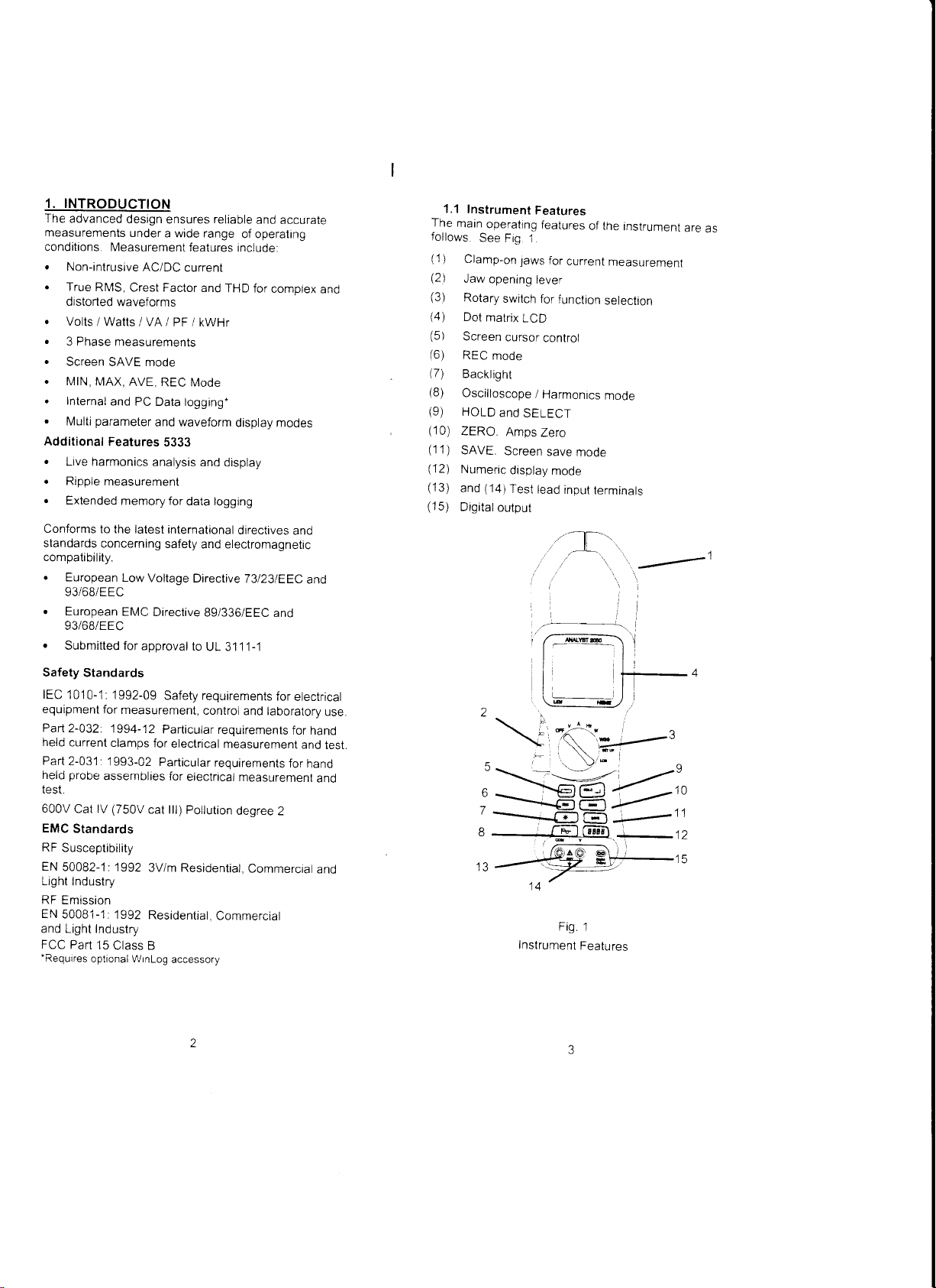
1.1
Instrument
The
main
follows.
(1
Clamp-on
)
(2)
Jaw
(3)
Rotary
Dot
l4l
(5)
Screen
(6)
REC
(7)
Backlight
(B)
Oscilloscope
(9)
HOLD
(10)
ZERO
(1
1
SAVE.
)
(12)
Numeric
(13)
and
(15)
Digital
operating
See
Fig.
laws
opening
switch
matrix
LCD
cursor
mode
and
SETECT
Amps
Screen
display
(14)Test
outpul
5
6
7
8
IJ
Instrument
Features
features
1.
for
current
lever
for
function
control
/
Harmonics
Zero
save
mode
tead
input
'T-.,
-,/'
Fig.
of the
measurement
selection
mode
mooe
terminats
'\.
1
Fealures
instrument
'
---
are
as
1
Page 4
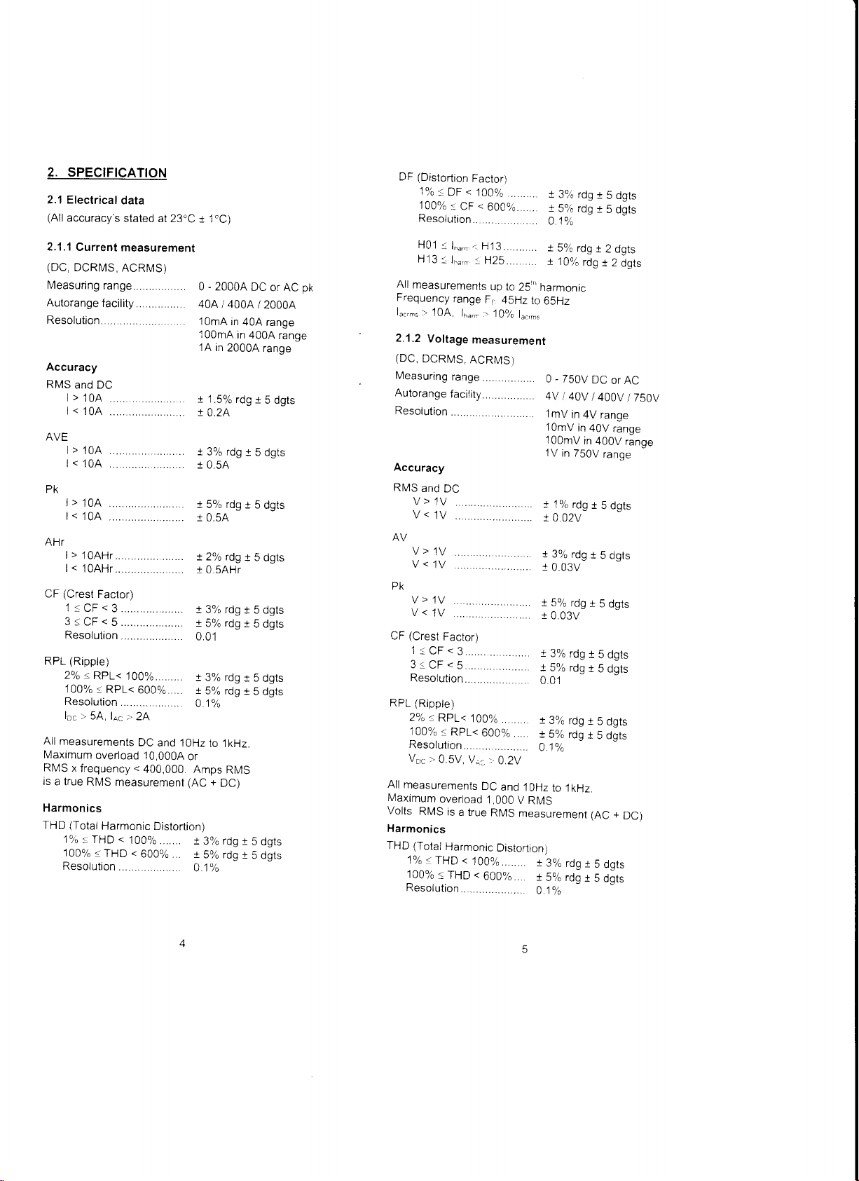
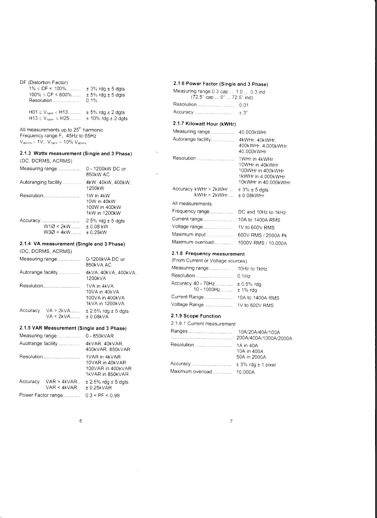
2. SPECIFICATION
2.1 Electrical
(All
accuracy
2.1,1
Current
(DC,
DCRMS,
Measuring
Autorange
Resoluiion......
Accuracy
RMS
and
>
|
<
|
AVE
>
|
<
|
data
s stated
at 23.C
measurement
ACRMS)
ran9e...............
faci1ity..............
DC
10A
...... .
10A
10A ............
10A ...
..........
........,.
........
......
t 1"C)
0 - 20004
40A/4004/20004
1OmA
100mA
1A in
t15%rdgr5dgts
r
0.2A
t
3% rdg
I05A
DC
in
40A
in 4004
20004
t 5
or AC
range
range
range
dgts
pk
(Distortion
DF
1%.:.
100%..
DF
Factor)
<
100%
<
CF
600%
Resolution..............
H01
a lh,,n.-:
H13.1h",,
All
measurements
Frequency
'10A,
1".,., >
2.1.2
Voltage
H13....
:H25...
up to
range
F,,
16",- :.
10%
measurement
..
251',
45Hz
1".,,,,.
t
3% rdg
t
I
5% rdg
5 dgts
t
5
dgts
01%
t
5% rdg
t
rdg
2 dgts
r 2
dgts
t 10%
harmonic
to
65Hz
0 - 750V
DC
or
AC
4Vt40Vl400v/750V
1mV
in
4V
in
750V
in
in
range
40V
400V
range
range
range
1OmV
100mV
1V
PK
>
|
10A ..........
<
|
10A
..........
AHT
'1OAHr.........
>
|
l<
1OAHr.........
(Crest
CF
Factor)
1<CF<3.......
3sCF<5.......
Resolution
(Ripple)
RPL
2%
RPL<
100ok.
RPL<
Resolution
loc >
5A,
lrc >
All
measurements
Maximum
RMS
is
x
frequency
a lrue
overload
RMS
Harmonics
(Total
THD
1%.
THD
1009".
Harmonic
THD
Resolution
+
:
r
! 2'k rdg
I
t 3%
...
.......
100%.
600%....
t5%rdgr5dgts
001
. ..
.
t 390 rdg
. x
0
2A
DC
and 1OHz
10,0004
<
400,000
or
Amps
measurement (AC
Distortion)
<
100%
<
600o,o .
+ ?0.- .d^ + A r^r-
1590
01%
F,o/-
rd^ ! A i^l^
/U
J
IUV
0.5A
0.sAHr
rdg
5% rdg
1%
to
1kHz.
RMS
+
DC)
rdg
A J
UgTJ
r 5
dgts
t 5 dgts
: 5
dgts
t 5 dgts
r
r ugrJ
t
5 dgts
(Rippte)
RPL
2o/o
<
RPI<
100ok.
RpL<
Resolution......
VDc
>
0.5V.
All
measurements
Maximum
Volts
overload
RMS
is
a true
Harmonics
THD (Total
Harmonic
1o/o.THD
100%
< THD
<
Resolution.......
100%
........
600%....
'.
Vi:_
0.2V
DC
and
10Hz
1,000
V
RMS
RMS
measurement
Distorlion)
100%........
<
600%
...
t lok
r
0.02v
t 3%
t
0.03v
t 5%
r
0.03V
t
3%
! 5%
0.01
r
3%
rdg
t5%
A.1o/a
to 1kHz.
r
3%
rdgt
t
S% rdg
O.1o/o
rdg
rdg
rdg
rdg
rdg
rdg
t
r
5 dgts
t
5 dgts
r
5
t
5 dgts
t
5 dgts
r
5
t
5 Ogts
(AC
5
dgts
5 dgts
dgts
dgts
+
DC)
Page 5
(Distortion
DF
lok'100%<cF<600%
Resolution
HO1 5 Vn",,< H13...
H13<Vn",.:H25..
All measurements
Frequency
V"",,," r'
2.1.3
Watts measurement (Single
(DC,
DCRI/S. ACRN/S)
Measuring
Autoranging
Resolution......
Accuracy
2.1.4 VA
(DC,
DCRMS,
Measuring
Autorange
Resolution.......
Accuracy
2.1.5
VAR Measurement (Single
Measuring
Auotrange
Resolution.......
Accuracy
Power
Factor)
<
100%....
DF
up to 25''' harmonic
range
F6 45Hz to
1V, Vr",",
. .... .. .
Factor
;'
10% V,",,""
ran9e...........
facility .......
<
wlz
2kW ,
<
w3a
4kw
measurement (Single
ACRMS)
ran9e................
faci1ity...............
>
VA
2kVA......
vA < 2kvA......
ran9e,..............
faci1ity..............
>
VAR
4kVAR
<
VAR
4KVAR
range .
. ... ., . . .
I
rdg
396
t 5
t
5%
01%
t 5% rdg
+ 1no/^ r.ld + ) .l^ta
65Hz
-
1200kW
0
dgts
rdg
I 5 dgts
t 2 dgts
and 3 Phase)
DC
or
8sOKW AC
4kw,
40kw, 400kw,
1200kw
1W in 4kW
10W
in 40kW
100W
in 400kW
1kW in 1200kW
4o/^
)
rdn + 6 .ldfa
t 0.08 kw
t
0.25kw
and 3 Phase)
0-'12OOkVA DC
850KVA AC
4kvA, 40kvA.
1
200kvA
1VA
in 4kVA
1OVA
in 40kVA
100VA in
lkVA in 1200kVA
^o,^
+ 2
J 0.08kvA
and 3 Phase)
O . BsOKVAR
4KVAR.4OKVAR.
4OOKVAR.
lVAR
in 4kVAR
1OVAR
100VAR
IkVAR
t 2.5% rdg
r 0.25kvAR
0.3<PF<0.99
or
400kvA
400kVA
rd,^ + q d^lc
S5OKVAR
in 4OkVAR
in 400kVAR
in
850kVAR
1 5 dgts
2.1.6
Power
Measuring
(72.5'
Resolution
Accuracy
2.1,7
Kilowatt
Measuring
Autorange
Resolution
Accuracy
All
measurements
Frequency
Currenl
ran9e...........
Voltage
ran9e...........
Maximum
Maximum
2.1.8
Frequency
(From
Current
Measuring
Resolution
Accuracy
Currenl
Voltage
2.1.9
2.1
Ranges
Resolution
Accuracy
Maximum
10
Range.............
Range
Scope Function
.9.1
Current
.....
over1oad............
Factor
(Single
range
0.3
cap.. 1.0
cap
0' .
(kWHr)
Hour
range
...............
faci|ity
.. .... .. ..
kWH'>
2kWHr...
kWHr<
2kWHr....
range
.,....
input.........
overload...
measurement
or Voltage
range
.........
40,70H2..,..
-
1000H2.
............
measuremenl
......
phase)
and
3
..
0.3 ind
72
5" ind)
0.01
i3"
40,000kWHr
... . .
4kWHr,
400kWHr,
4O,000kwHr
lWHr
in 4kWHr
I
OWHr
in
1OOWHr
l kWHr
in
10kWHr
g
r
396
a
10.OBkWHr
..
DC
and 10Hz
. 10A
to 14004
'1V
..
to
600V RN/S
. 600V
sources)
. 1OHz
.
.
.
. 10A
. 1V
Rl\4S
1000v
RMS
to l
01Hz
t 0.5%
rdg
! 1ok
rdg
to
14004
to
600V
10tu20A/40A/100A
200tu400AJ1
1A in
40A
10A
in
40OA
50A in
20004
t
3% rdg
10,0004
4OkWHr,
4.00OkWHr
40kWHr
in
400kWHr
4.000kWHr
in 40.000kWHr
f,gt5
to l
kHz
R|VS
/
kHz
RMS
r 1
pk
20004
/ 10,0004
RI\4S
000A/2000A
pixel
Page 6

2. 1
.9.2 Voltage
measurement
Ranges
^.'
Kesotuuon.......
Accuracy
Maximum
Fronr rennrr rrnno
Time
. .. .. .. .
overload .........
'""v"
base......
50msidiv
Refresh
rate....................
2.1.10
Digital
output
RS-232
9600 baud 1
Requires
2.2
2.2.1
Backlit
Interface
start bit B
WinLog
General Data
Display
dot matrix
to a PC
4V t10Vt20Vt40Vl100V
200v/400v/1
100mV
1V
10V
31 .25V rn
! 2oh
l
OOOV RMS
..
DC
2ms.4ms,
0.5 seconds
data bits
interface
and software
LCD 160x128.
il
n
H
Ftli T=t::
I
n
r,, 1
in 4V
in 4OV
in 400V
'1000V
rdg + 1
and 1 OHz to
1Oms,
'1
stop
bit
2?=.2
200.E
315 E
t 414
3 5.5
'...
000v
pixel
'-.
--.---
600H2
Fl
Fl,ll
Hts.
tr!
2.2.3
Environmental
FOR
INDOOR
Reference
,4.'a + 1oa
Operating
Temperalure
Temperalure
Maxim^umrelative
3]:9 (-87:f
at 40'c
Maximum
2.2.4
Mechanical
Dimensions
Weight
Case
material
Jaw
opening
Jaw
capacity..............
Accessories...............
Cleaning
2.2.5
Power-up
power-up
At
seconds
battery
lifetime
backlight
mode,
the
USE
conditions.
temperature
coeff.
coeff.
decreasing
)
(104'F)
operating
inc.
batteries..
the
following
indicating
is
displayed.
When
the
instrument
ONLY
All
O"C
of
current
voltage
of
humidity
tinearty
altitude
..
..
..
.
..
..
. The
screen
the
battery
display
is ready
accuracy,s
to
stated
50.C (32.F
<
t0.15%
of rdg per.C
< t0.15%
80% for
lemperatures
to
50?6
retative
2OO0m
Length
300mm ('12
gSmm
Width
Depth
52mm
B20g/1Blbs.
Bayblend
TB5MN
60mm
58mm
diameter
probes
Voltage
Carrying
Operator's
with
case
manual
unit
can
an
lsopropanol
impregnated
Do
not
use
other
stat.Ls.
with
changes
for
abrasives
solvenls.
is
displaved
The
and
without
to the
use.
at
to
122"F)
per
of rdg
humidiry
inches)
(3.75
inches)
(2
inches)
be
cleaned
cloth.
for
5
remainino
the
digital
up
or
.C
to
2.2.2 Power
Battery type
Battery
life
typically
24 hou.s
12
hours
Supply
1.5V
Alkaline AA MN
(backlight
(backlight
f1If,
HrrE:tj..an
off)
on)
iq.5!
1500
or
lli
IEC
'.=,.
LR6 x
6
Page 7

3. OPERATING
lnternational
A
EI
3.1
Rotary
Switch
The instrument
and an
functions
B key keypad.
iollows.
OFF
A
nz
w3z
Set
up
Log
INSTRUCTIONS
Symbols
lToortanr
(See
Double lnsulatron
/ Keypad
are
The
rotary
Instrument
Voltage
Current
Frequency
Power
phase
3
Options
Logging N,4enu
In{ormarror
Manual)
selections
selected
switch
off
/ THD
Power
Menu
by a rotary
positions
swttch
are
as
SAVE
Mode
This
function
whrch
can
the
5333
captured
Pressing
text
both
simultaneously
the
on the
12345678
HoLD
-J
whole
be
l.I'
key to
Repeat
from
recovered
Use the
CLEAR
locations
The
can
instrument
the
SAVE
mode
3.2
key
of
operation.
Voltage
allows
either
the
waveforms
be
waveiorm
SAVE
mode
screen:
SAVE
screen
key
to
select
this
1 to
B.
is
RECOVER
move
either
process
saved
at a later
has
powered
been
returns
the
measurement
capture
of up
or numerical
and
harmonics
in
one
memory
key
brings
the
cursor
SAVE,
to
select
in
the
selecled
-
date
even
off.
instrument
of
RMS
to
B screens
data.
screens
location.
up the
followinq
CLEAR
and
the
RECOVER
one
of the
location
after
back
the
to
the
Voltaqe
A
second press
or DC
For
are
or
SAVE
and
of
normal
When
switching
calabration
push
The
i
Optron
2
HOLD
3.
REC
/
ZERO
5
Backlight
6
SAVE
7
Oscilloscope/Harmonics
B
Numeric
the
lo finish
button
before
keys
cursor movement
and Option
(Min,
mode
ON
/ OFF
Display
instrument
ON, wait
taking measurements.
are
as follows:
and
screen
select
Max. Av)
(5333)
mode
for the
-6
mode
auto
2
changer
SAFETY
To
to
any
range
8
.
possible
avoid
the
instrument,
voltage
of
the instrument
Move
the
Insert
the
the
instrument.
terminal,
Apply
the
read
the
displayed
Use
the
that
rotary
test
and the
test leads
I
displayed
Screen
Screen
=
1
(5332)
2
nz
Screen
.
Use lhe
,
Use
voltage
,
Use the
content
individual
,
Use
(5333)
2
HOLD
'=
the
and
!:
of the
harmonics
the
BBB8
lrr"
16s
lr'r'
electric
do
might
switch
leads
Connect
black
voltage.
key
to
V DC,
=
=
V
key
to freeze
key
-:---
key
voltage
key
to return
WARNTNG
shock
not
attempt
exceed
-
600Vrms
to
the
V
into
the
sockets
the
red
lead
to
to
the
circuit
See Fig.
change
the
V
(AC
RMS
V
RMS,
VAv.
RN4S,
VAv.
the
to
display
key
to
change
to
display
and
the
(5333
only)
to
the
and
to
the
maximum
and
position.
on the
lead
to the
the
COM
under
2.
parameters
+
DC)
pk,
V
pk,
V
V
display.
the
waveform
the
the
harmonic
--key
digital
lkHz
front
V
terminal
test
and
V
CF,
CF, V
of the
timebase
to
select
disptay.
of
V
Rpl
10
11
Page 8
Use the
REC key
i*1
169
of the
screen readings.
exit.
(
b
key to
to enter the
show the
MAX, MlN.
Press
-F-
L
-i<{'
[r
\-
.i
\\
i; \' l-
F
r \\,r-
!.J
-\-/
) -A
t6t If Jl
i c=).-=l
I
Eltlttal
I
,_
RECORD
AVE
the REC
I
mode.
disptays
key
again
Use
to
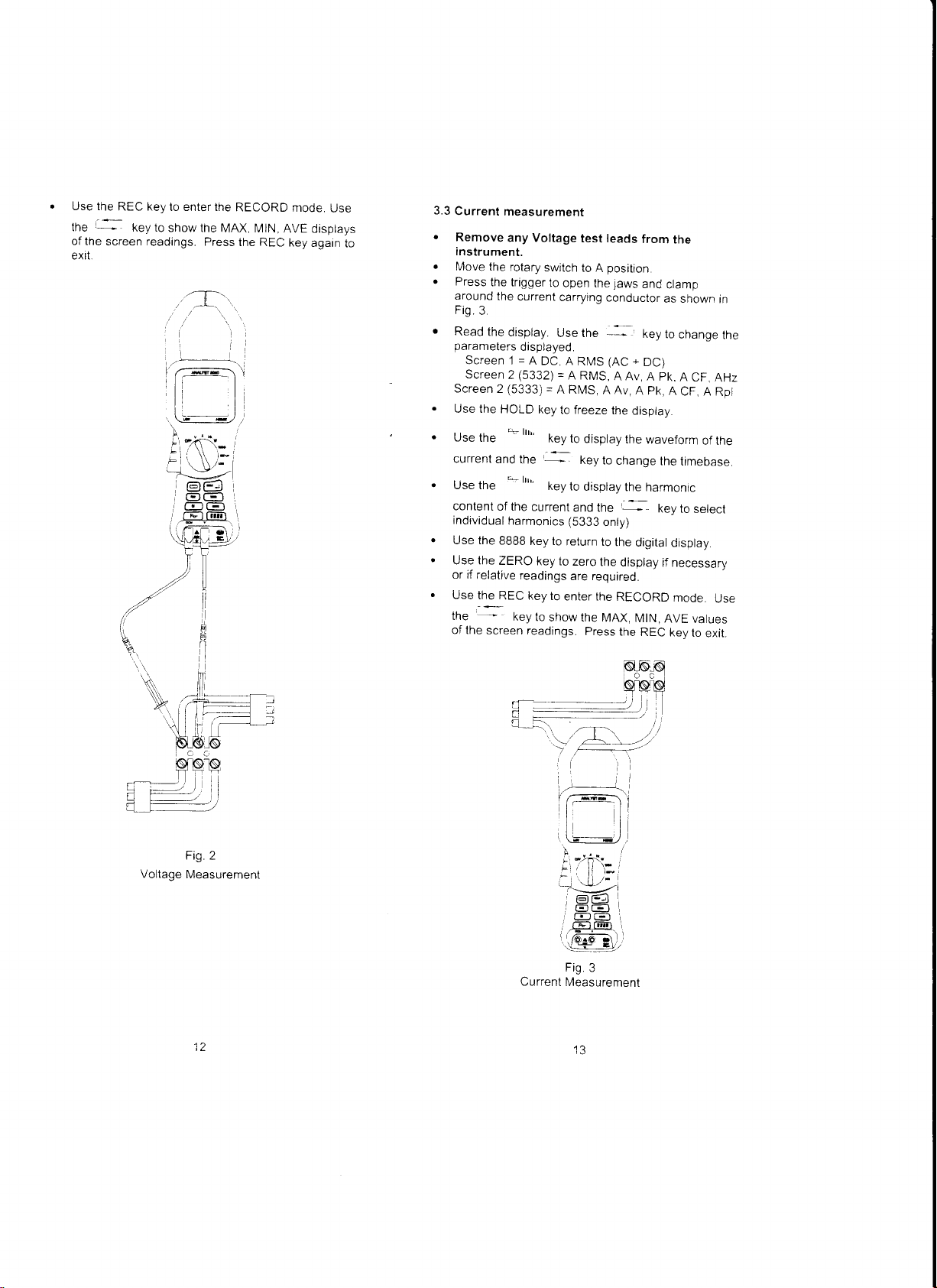
3.3
Current
.
Remove
instrument.
o
Move
o
the
Press
the trigger
around
the
Fig.3
r
Read
the
parameters
Screen
Screen
Screen 2 (5333)
Use the
HOLD
Use
the
current
and
Use the
content
of the
individual
Use the
Use the
or if
Use
the
of the
88BB
ZERO
relative
the
REC key
screen
measurement
any Voltage
rotary
switch
to
open the
current
carrying
display.
Use the
disolaved.
1 = A
DC, A
RMS
=
(5332)
2
*1""
the
+1""
harmonics
readings
key
=
A RI\4S,
key
to freeze
key to
-:key
current
key to
return
key to
to
enter the
to
show the
A
to
and the
(5333
zero
are required.
readings.
test leads
position.
to
A
jaws
conductor
*l
+
(AC
RMS,
AAv,
AAv,
the
display
disptay
the
key
to
change
display
the
--
only)
to
the
the
display
RECORD
MAX,
Press
the
from
the
and
clamp
as shown
keV
to
DC)
pk.
A
pk,
A
A
waveform
the
harmonrc
key
digital
display
if necessary
mode.
MlN,
AVE
REC
key
in
chanqe
the
A
CF,
AHz
CF, A
Rpl
of the
timebase.
to
select
Use
values
lo
exit.
Voltage
Fig
2
Measurement
Current
Measurement
IJ
Page 9

3.4 Measurement
(Single
Phase)
o
Move
the rotary
o
Insert
the tesi
the instrumenl.
terminal,
.
PTess the
on the
the
and
trigger
current
Fig.4.
.
Read
the
parameters
a
Use the
U1e_the
the
display.
displayed.
Screen
1 = kVA,
Screen 2
=
V RMS,
HOLD
REC key to
key to
show the
screen readings.
exit.
of Watts
/
switch to the
leads into
Connect
carrying
black
to
open the
the
the red
lead to
conduclor,
Use the
kW.
kVAR, PF.
A RMS,
key to freeze
enler RECORD
MAX, MlN,
Press
VA
/ PF
W
sockets
the
jaws,
--
kW, PF,
the
the
REC
/ kWHr
position.
on the front
lead to
the V
COM terminal.
and
clamp
as shown
key to
change
kWHr
AHr
display
mode
Use
AVG
displays
key
again to
them
in
of
the
the
of
3.5
Measurement
balanced
Move
A screen
method
Insert
the
instrument.
terminal
Apply the
Red lead
Black
Press
around
Fig
5.
.
Read the
parameters
Screenl
Screen2
.
Use the
.
Use
the REC
1
1-
the
screen readings.
exit
this mode.
gives
W3Z
system.
of W
system (3
-r
Phase)
Fig
Watts
3Z
/ VA / PF
the rolary
switch
prompt,
Fig.
5, indicates
/ kWHr
5
Configuration
to the W3Z
position.
the
in a
L.l
LI
L1
above
of conneclion.
the
test leads
and the
test leads
to Phase
lead
the trigger
the current
display.
=
=
HOLD key
key to
lhe
total
into the
Connect
black lead to
to the
L2
to Phase L3
to
open the
carrying
Use the
displayed.
kVA, kW,
V RMS, A
to freeze
key to
enter RECORD
show the
Press
power
sockels
the red lead
the
circuit
jaws
Phase
'
|
-
kVAR, PF,
RMS, kW,
the display.
MAX.
MlN, AVE
the
REC key
based
on a
on the
front
to the
V
COM terminal.
under tesl:
and
clamp them
L1, as
shown in
key to
change
kWHr
PF, AHr
mode.
Use the
displays
again
balanced
of
lhe
of
to
Single
Fig 4
Phase
Watts Measuremenr
Page 10
3.6
Frequency
.
Move
.
Insert
the
terminal,
.
To
measure
apply
and
.
To
measure
lrigger
current
read
.
Use
displayed.
Screenl=Hz,ACRMS
Screen
.
When
test
a
current
displays
(providing
frequency
VRMS
.
Press
display.
.
Use
-
--
.
the
screen
exit
this
Additional
.
Use the
current
timebase.
.
Use
contenl
of the
select
individual
/ THD
the rotary
the
test
instrument.
and the
the frequency
the test
read
the
the
leads
the
the
leads
the
displsy.
the
lo
open the
carrying
display.
=
2
Hz(F"),
configured
connected
carrying
the frequency
ARIUS
measurement
>
1V),
otherwise
the
HOLD
REC key
t
"y to
show
readings.
mode.
features
r-
lrrr'
/ voltage
^-
lrt'
currenVvoltage
harmonics
Measurement
switch
to
leads
into
the
Connect
black
lead
to
the
frequency
jaws.
conductor.
key to
and
and
change
ACRMS.
to
measure
and the
conductor,
of the
>
10A).
will
---.-
/ ZERO
to
enler
the
MAX,
press
5333
key
to
display
the
key
to dasplay
position.
the
Hz
sockets
the
red
lead
to
the
COM
of the
voltage
circuit
as
of the
current,
clamp
as shown
parameters
the
THD,
DF
power
jaws
clamped
lhe instrument
current
lf ARMS
button
RECORD
.-
r.
and the
<
be
made
wilt
be displayed
to
freeze
MtN,
AVE
lhe
REC
the
waveform
key to
the
harmonic
on
the front
to
the
terminal.
supply
shown
press
them
on the
in Fiq.
(Fig.
4)
source
10A,
a volls
(providing
the
mode.
displays
key
again
change
-
-.
key
V
in
Fiq.
the
3 and
with
the
arouno
Use
tne
of
to
of
the
the
to
of
II
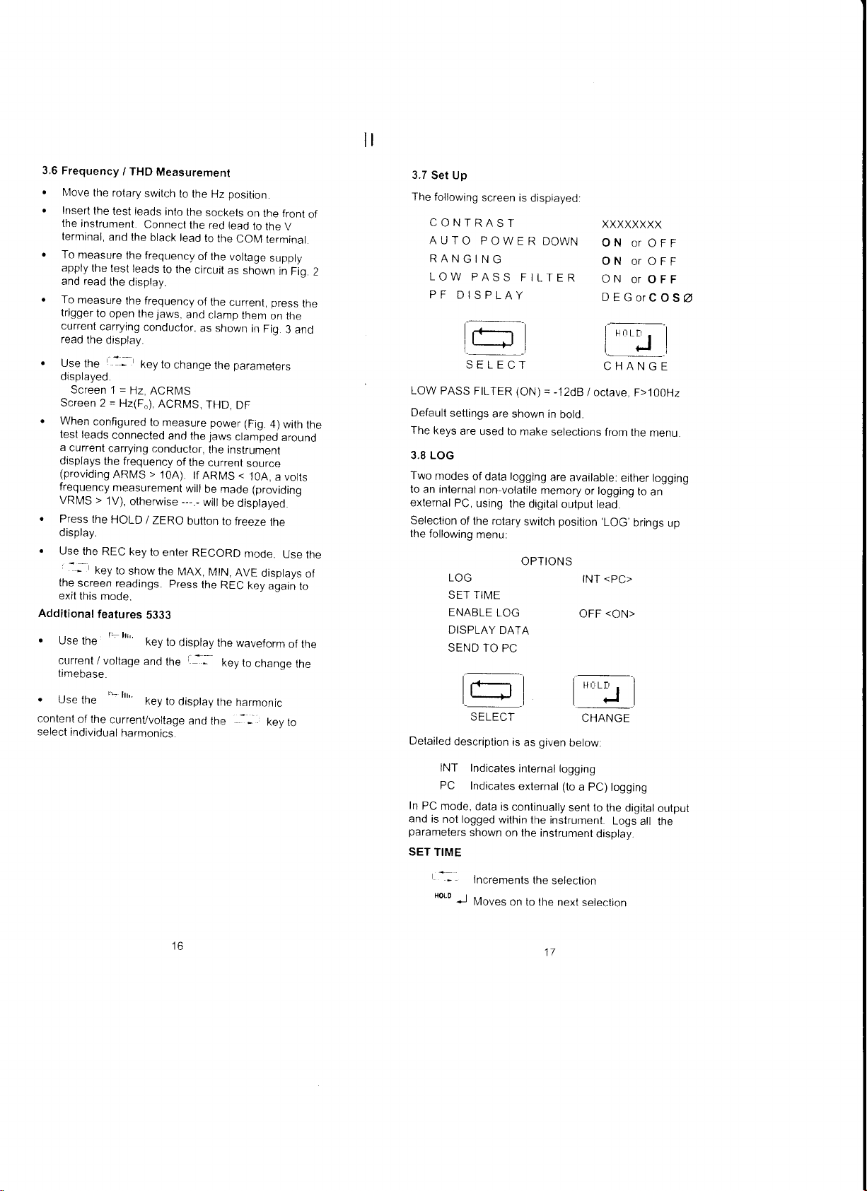
3.7
Set Up
The
following
CONTRAST
AUTO
2
RANGING
LOW
PF
LOW
Default
The
keys
3,8 LOG
Two
modes
lo
an internal
external
Selection
the
following
Detailed
screen is
POWER
PASS
DISPLAY
t---r
I rF-r I
l+l
SELECT
PASS
FILTER (Ottt1
settings
are
used to
of data logging
non-volatile
PC,
using
of the rotary
menu:
LOG
SET TIME
ENABLE
DISPLAY
SEND TO
lr-r I
l+l
SELECT
description
are
shown in
the
LOG
DATA
PC
is
displayed:
DOWN
FILTER
= -120U
bold.
make
selections
are
available:
memory
digital output
position
switch
OPTIONS
l-r
given
as
below.
XXXXXXXX
ON or
ON or OFF
ON
DEGoTCOSU
t-* f
|
I {-Jl
CHANGE
i octave,
from the
logging
or
lead.
'LOG'
<PC>
INT
<ON>
OFF
OFF
or OFF
--
| |
F>100H2
either
to
brings
i
CHANGE
menu.
logging
an
up
to
INT
PC
In
PC
mode.
and is
not logged
parameters
SET
TIME
*--
'o'o
J
Indicales
Indicates
shown on lhe
Increments
Mou".
data
within
internal
external
is
continually
the instrument.
on to the
logging
(to
a PC) logging
sent to
instrument
the
seleclion
next
17
the
Logs
display.
selection
digital
all
output
the
Page 11

For
ease
then
minutes,
minutes.
and the
of operalion
the
sta.t is
and
The
maximum
automaticaily
the
end time
minimum
sample t
used.
Start /
Stop
and loggrng
requrred.
CURRENT
START
END
SAMPLE
INTERVAL
EXIT
The
maximum
=
5332
=
5333
The
maximum
battery
is
an average
ENABLE
The
logging
menu.
insufficient
defined
When
internal
commence
measurement
key.
All
logged.
memory
SET TIME
screen
Logging
through
tey
before
lf
PC logging
on the inslrument
Logging
DISPLAY
On
entry
have
been logged
increments
parameter
ONE
number
2000
readings,
5000
readings,2500
logging
life (24hrs
and
)
over the
LOG
function
The
low
baltery
battery life
in the
SET TIME
logging
within
5 seconds
screen
data displayed
'MEMORY'
to
complete
menu.
timer
flashes
Once logging
counts
down
will terminate
moving
the
end of
is
enabled,
rotary
the
display
will
not terminate
DATA
to lhis
menu
are
through
the list,
for
displsy
ARIVS,AAv,APk,ACF
EXIT returns
lo the
previous
if
the
current time
reset
is
set to the
sample interval
hour.
inlervals
TIIVE
TIME
TIME
HR:MIN
HR:MIN
HR:MIN
MIN.SEC
points
of
1000
that
sets
sets
duration
is determined
the memory.
period.
sample
can be
enabled
symbol flashes
to
complete
menu.
is
enabted
the
of
selecting
with
the
rotary
the
on
selected
if
the logging
there
session
has
the remaining
if
lhe
screen
switch
the logging
a list
or
session.
all
measurements
will
be logged
if the
screen
of the
displayed.
and the
For
example:
menu.
is
chanqed,
to
this
time
start
time
.1
is
second,
A 24hour
can
be selected
can
logged
be
ol 2
or 400
of 2
1000
or
Data
being logged
from
the
if there
the
logqing
logging
will
the
switch
and
screen
is insufficient
defined
commenced
loggino period.
display
is changed
pressing
the
appearing
to the
is
chanoed.
parameters
The
'o'o
which
'-
key
J
kev
i
60
+
60
clock
is
as
sels of
sets
bv
the
main
log
is
session
--
r
will
be
in
the
an
'
1-
pC.
selects
is:
of
5
on
It
On the
chart
display
screen
shown vs
allowing lhe
select
The
5
SEND
This
lhe
selecled
option
On
data has
time,
and
user to return
menu.
lFl
I1
iltl
t'lIf{
lE.:u
FilE :t:1.
FF:Egg {r
following
informalion
LOGGING
DURATION
SAMPLE INTERVAL
MIN MAX
AVE
TO PC
allows
lhe user
program.
WinLog
"DOWNLOAD
within
the WinLog
selection
of SEND
been
downloaded
the single
an EXIT is
to
the logging
t_tlt
5Er r=
tlB
is
also displayed:
to
download data
Previously
LOG" from
program.
TO PC
the text will
to the
3.8 WinLog
WinLog
is the
5333 Power
log
electrical
dala to
a Personal
x',rra,.
iiir
ft,|!.i)f)',
-@n!q
il;n
PC residenl
Meters.
power
_
software for
The
software is
measurements
Computer
Pft*nt
3hrvd"!
for further
[:l$-
qtdrr
*J k
parameter
displayed
on the
parameter
.
:r:
El
T
T=
HR:MlN
\ = MIN
to a PC runninc
the user must
the Instrr-rment
flash
PC.
the new
used to
or download
analysis
._,i
rlDa
L.mn
J;
is
screen
SEC
have
until
all
5332
&
continuarry
stored
'-]J1
.
1B
Fig. 7 Winlog
19
Software
Page 12

Key features
.
.
.
.
.
.
4.
SAFETY
The
instrument
lEC1010-2-032
Categoryl
UL
31
Directive
IEC
1010
features:
o
Installation
working
be expected
CAI lV,
exceed
.
In
design
conductivities
Safe
responsibility
qualified
and
or
and
Safety
valid
to identify potential
risk
of electrical
short
the
risk
leads
guidance
use
by
lf the
the
manufacturer.
equipmenl
inclr-rde.
Easy
to
use Windows
presentation
Data
chart modes
Waveform,
Harmonics
Logging
harmonics
Sirnple
applications
1-1
1
pollution
a
operation
their employees
risk
circuits.
is
constructed
Electricians'
instrument
of up to
exporling
has
Installation
lV
600V Pollution
. Conforms
7
3l23tEEC
is
a safety
categories
voltage
in
the
the
maximum
peak.
BkV
degree
of the
instrument
due lo
of
the instrument
of
the operator
and/or
authorised.
Legislation
assessments
injury
Where
significant,
note
GS38
is
used in
then thc
may
be impaired.
format
in
display
harmonics
analysis
been
and 93/6BrEEC.
standard
to
sources
in
is
and
of waveforms
parameters,
5
of data
and
designed
Category
deqree
with
the
EEC
which
I
to lV relate
overvoltage
measuring
2
condensation.
are reminded
requires
of all
such
the assessments
then
accordance
'Electrical
advised.
environment.
expected
environment
can
cope
who
Users
them
electrical
of
electrical
as from
the use
Test
a manner
protection provided
mimic.
table
data
download
waveforms
trends
inlo
to
comply
with
lOvervottaoe
2 and
Low
Voltaoe
has
the
followinq
the
maximum
transienls
transients
is
with
not
that
the
internal
with
transient
the
must
be
of
this equipment
that Health
to
carry
work.
danger
inadvertent
show
of
fused
the
HSE
Equipment
specified
and
and
other
can
60OV
must
not
suitably
out
so as
and
that
test
for
bv
bv the
Maximum
Current
uninsulaled
frequency
conductors
Voltage:conduclor
between
frequency
lmportant
.
.
.
.
USE
LEADS
Degree
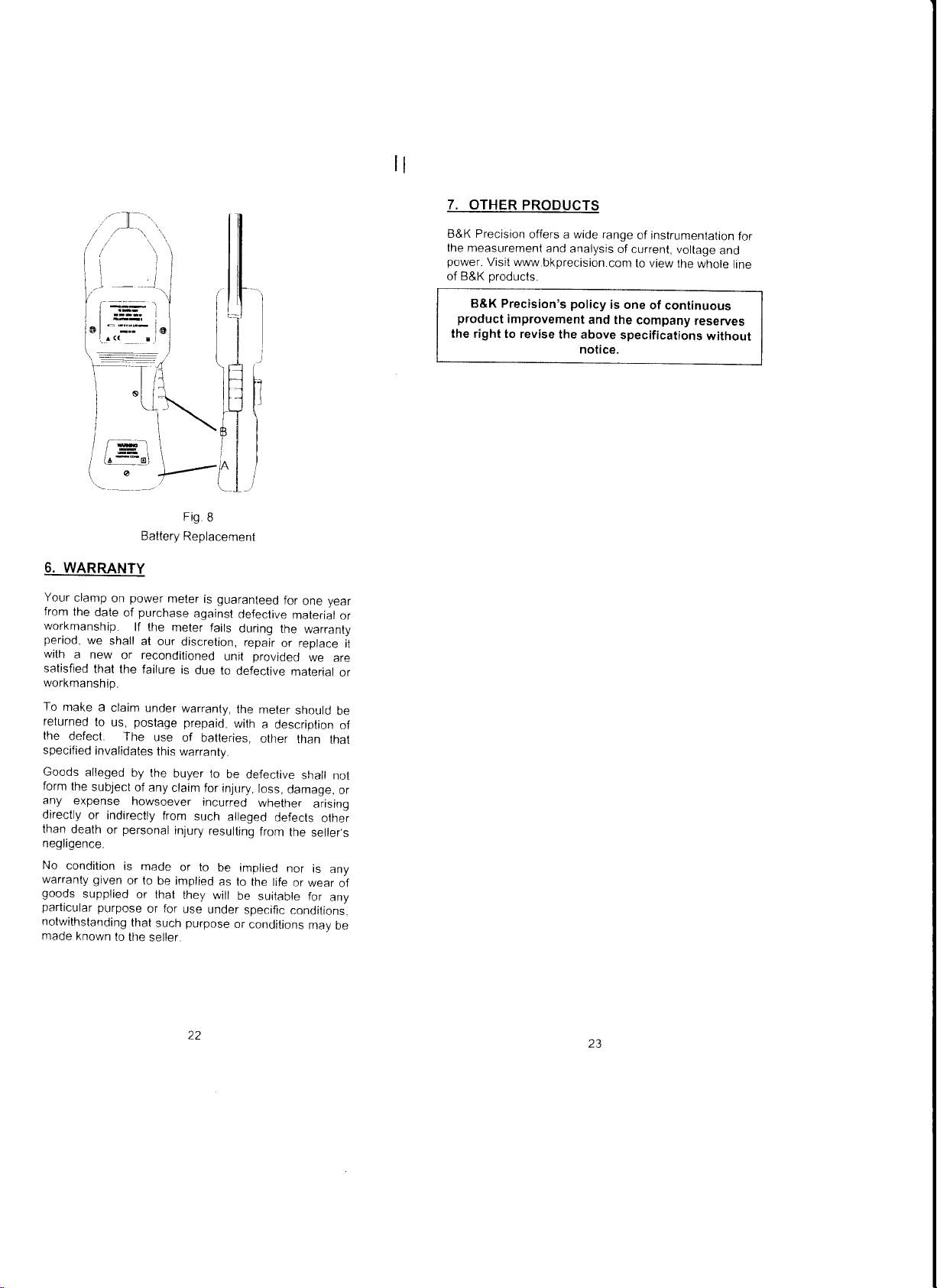
5. BATTERY
Replacement
invalidate
Fit
equivaleni
E
minimum
Before
from
To
o
.
.
.
Safe Voltage
:- 600V
conductor
of
only.
600V MAXIN,lUM
and
V and
of 1 kHz
Information
The
instrument
Do
not attempt
or voltage
inslrument.
The
unil is not
be
brought into
Frequently
for
damage.
or
does not function
ONLY
SUITABLY
TO IEC
2).
the
only Battery
x 6.
will appear
operating
removing
that
all
external voltages
the instrument.
leads
change
the
Swilch
off the
Undo
the retaining
cover
and lifl
Replace
Ensure
screws
the
the
tightened,
MAXIMUM
1kHz.
ground.
COM terminals
higher than
inspect
lf the
1010-2-031.
REPLACEMENT
with other than
warranty.
Type
on the
SAFETY
and unclamp
batteries.
instrument
the cover
used
battery
ground
and
This
limitation
600V MAXIMUM
is intended
to take
any measurement
the
hermetically
contact
the
test leads
instrument
properly,
RATED
1.5V Alkaline
LCD display
batlery voltage
WARNING
the battery
For
see Fig
screws
clear
batteries
cover is replaced
before
AC R[/S
AC RMS
with
the
the
further
or DC
and maximum
applies
to
or DC
and a maximum
maximum range
sealed
surface water.
(600V
are disconnected
certainty remove
(A
AC RMS
for
indoor
and should
and the
physically
is
it
should not
VOLTAGE
CAT tV
specified
cover,
instrument.
B
and B)
of the
batteries
MN1500,
to indicate
has
been reached
make sure
on the battery
unit.
and
use.
between
unisulaled
between
or DC
use
only.
of
current
the
of
NOT
instrument
damaged
be used.
TEST
Poilution
will
IEC
LR6
that
the
all
the
locking
live
or
20
21
Page 13
1t
7.
OTHER PRODUCTS
'r
\(
\.i
I I
'|
-:::-
i@
|
l-llll
F
,
I
i \\ l-L
I \
Hi
, ,
/ la--o\ \ ,^ | |
-
'
'!-
6.
WARRANTY
Your
clamp
from
workmanship.
period,
with
satisfied
workmanship.
To
make
returned
the
specified
Goods
form
any
directly
than
negligence.
No
warranty given
goods
particular
notwithstanding
made known
on
the
date
we
shall
a new
that the
a
claim
to
us,
defect
invalidates
alleged
the
subject
expense
or indirectly
death
or
condition
supplied
purpose
lo
or reconditioned
The
personal
I I
rl
ill
lo
/
l,l lul
|r lrl
'l
\
\AT
1
o' ,--:^
Fig
B
Baltery
Replacement
power
meter
purchase
of
lf the
at
our discretion,
failure
under
poslage
use
this
by the
of any
howsoever
is
made
or to
be implied
or lhat
or for
that
such
the
seller.
is
against
meter fails
is
due
warranty,
prepaid,
of batteries,
warranty.
buyer
claim
for
incurred
from
such
injury
or to
they
use
purpose
,I
I
(l
I I
\-
ll
ll
tl
)
it
I
I I
i
\-l-/
guaranteed
clefective
dr.rring
repair
provided
unit
to
defeclive
the
meter
with
a
other
to
be
defeclive
injury,
loss,
whether
alleqed
resulting
will
under
be
as
or
implied
to the
be
specific
from
suitable
condilions
year
for
one
malerial
the
warranry
or replace
we
are
material
should
descriotion
than
lhar
shall
damage,
defects
nor is
life
not
arisino
othei
the
seller's
any
or
wear
for
any
conditions.
may
oe
be
or
of
or
or
of
B&K Precision
the measurement
power.
of B&K
B&K Precision's policy
product
the right
it
offers a wide
and
Visit
www.bkprecision.com
products.
improvement
to revise
analysis
and the
the above
notice.
range
of instrumentation
of current,
to
view the
is one
of
continuous
company
specifications
voltage
whole
reseryes
without
for
and
lirre
22
Page 14
ll
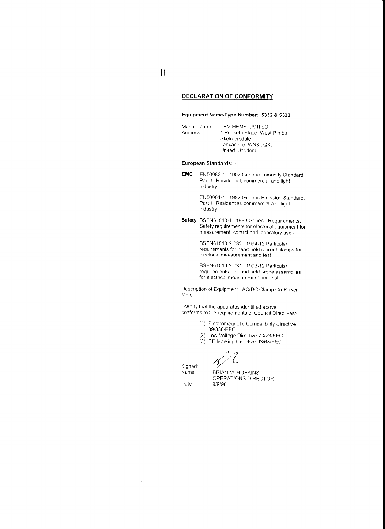
DECLARATION OF
Equipment Name/Type
Manufacturer. LEIV
Address: 1 Penketh
European
EMC
Safety
Standards:
EN500B2-1
Part
1. Residential,
industry.
EN50081-1
Part 1.
industry.
BSEN6'1010-1
Safety requirements
measurement,
BSEN61010-2-032
requirements
electrical
BSEN61010-2-031
requirements
for
electrical
CONFORMITY
Number:
HEME
Skelmersdale,
Lancashire,
United Kingdom
-
: 1992
Generic lmmunity
'1992
:
Residential,
rneasurement
Generic
: 1993
control and laboralory
for hand
for
hand
measurement
5332 & 5333
LIMITED
Place, Wesl
WNB
commercial
commercial
General Requirements.
for
electrical
. 1994-12
held
and test.
: 1993-12
held
Pimbo,
gQX.
and light
Emission
and
light
equipment
Particutar
current
clamps for
Particutar
probe
assemblies
and lest.
Standard.
Standaro.
use:-
for
Description
Meter.
I
certify
conforms
Signed
Name
n^r^,
of Equipment
thal the
to the
(1
)
(2)
(3)
: AC/DC
apparalus
requirements
Electromagnetic
B9/336/EEC
Low
Voltage
CE
Marking
.r" .' /
/1//
ERINN
OPERATIONS
9/9/98
identified
Cornpatibility
Direclive
Directive
;n1
L--
N,l HOPKINS
DIRECTOR
Clamp
above
of Council
73l23lEEC
g3/68/EEC
power
On
Directives:-
Directive
 Loading...