

Page 1
OPERATING INSTRUCTIONS
Crestfactor:≤3
Crestfactor:≤3
MODEL 2708B
DIGITAL MULTIMETER
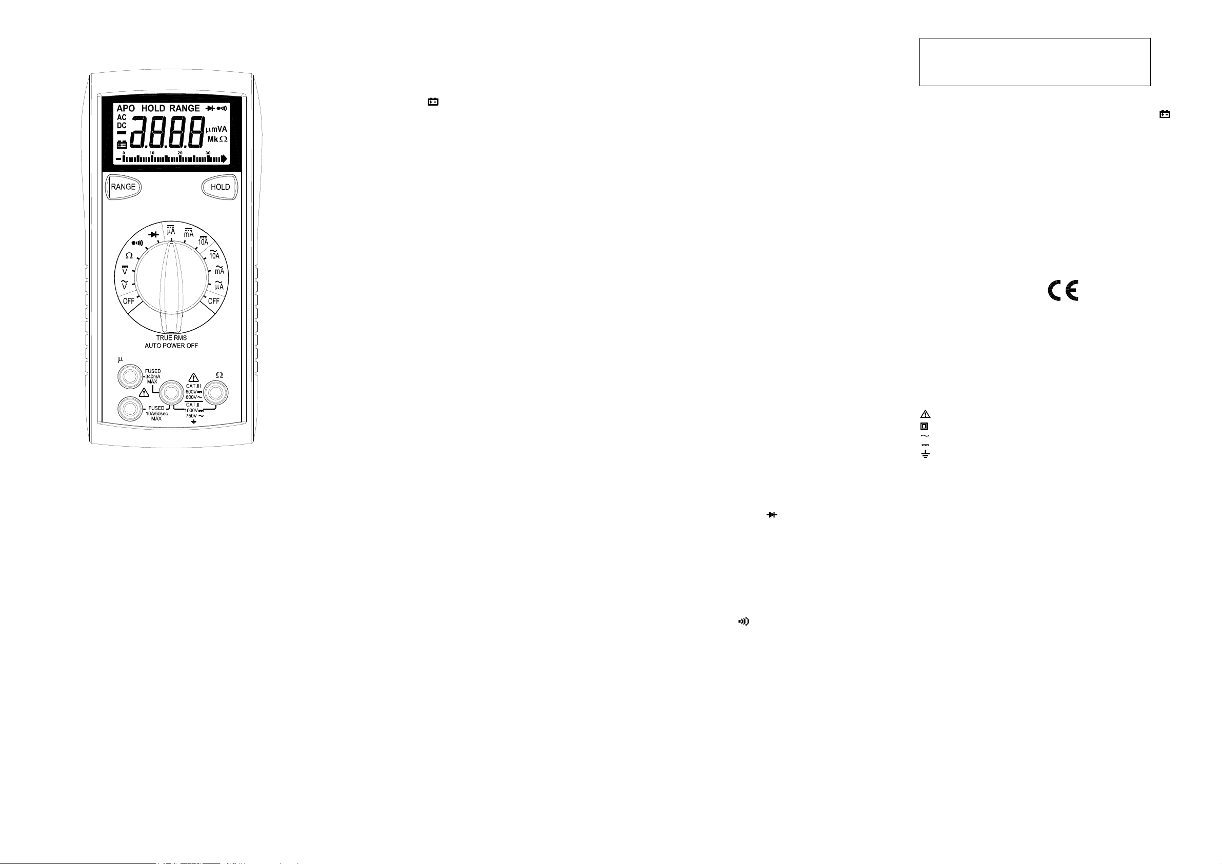
2708B
A mA
COM V
10A
SAFETY INFORMATION
The following safety information must be observedtoensure maximum personal
safetyduring the operationatthismeter:
Use the meteronlyasspecified in this manualorthe protection providedbythe
metermightbeimpaired.
Test the meteron a knownvoltage before usingit to determineifhazardous
voltage is present.
Do not use the meter if the meteror test leadslookdamaged, or if you suspect
that themeteris notoperating properly.
Neverground yourselfwhentaking electricalmeasurements. Do nottouch
exposed metal pipes, outlets, fixtures,etc., which might be at groundpotential.
Keepyourbody isolated from groundbyusing dry clothing,rubber shoes, rubber
mats,oranyapproved insulating material.
Turnoff power to the circuit undertestbefore cutting, unsoldering,orbreaking
the circuit.Small amountsofcurrent can be dangerous.
Use cautionwhen workingabove60Vdc or 30V ac rms.Suchvoltages pose a
shockhazard.
When usingtheprobes, keep your fingers behind the finger guardsonthe
probes.
Measuring voltagewhich exceeds the limitsofthemultimeter may damagethe
meterandexpose the operatorto a shock hazard. Alwaysrecognizethe meter
voltage limits as statedonthe frontofthemeter.
SPECIFICATIONS
Display: 3¾ digitliquid crystaldisplay (LCD) with a maximum reading of 3400.
Analogbar graph: 34 segmentswithmeasurements12times persecond.
Polarity:Automatic, positiveimplied, negativepolarity indication.
Overrange: (OL) or (-OL) is displayed.
Zero:Automatic.
Lowbattery indication:The
belowthe operating level.
Measurement rate: 2 times per second, nominal.
Auto poweroff: Approx. 10 minutes.
Operating environment: 0℃ to 50℃at< 70% relative humidity.
Storage temperature: -20℃ to 60℃,0 to 80% relativehumidity.
Accuracy: Statedaccuracyat 23℃ ±5℃, < 75% relativehumidity.
Temperature Coefficient: 0.1 x (specifiedaccuracy)per ℃. (℃ to 18℃,28℃ to
50℃).
Altitude: 6561.5 feet (2000m).
Power: Single standard 9-volt battery, NEDA1604, JIS 006P, IEC 6F22.
Battery life: 150 hours typicalwithcarbon-zinc.
Dimensions: 165mm(H) x78mm(W)x42.5mm (D).
Weight: Approx. 10.0oz.(285g) including holster.
Accessories: One set test leads,onespare fuse, 9V battery (installed),and
Operating Instructions.
is displayed when the batteryvoltage drops
" "
DC VOLTS
Ranges: 340mV, 3.4V, 34V, 340V, 1000V
Resolution: 0.1mV
Accuracy: ±(1 . 0%r dg+2 dgt s)
Input impedance: 340mV:>100MΩ; 3.4V:10MΩ;34V~1000V:9.1MΩ
Overload protection: 1000VDCor 750VACrms
AC VOLTS (TRUE RMS) (50Hz – 1kHz)
Ranges: 3. 4V,34V,340V,750V
Resolution: 1mV
Accuracy: ±(2.0% rdg + 8 dgts)50~ 1kHz on 3.4V, 34V ranges
Input impedance: 3.4V: >10MΩ;34V~750V:9.1MΩ
Overload protection: 1000VDCor 750VACrms
±( 2.0% rdg + 8dgts) 50 ~ 500Hz on 340V,600Vranges
CURRENT
Ranges: 340uA,3400uA, 34mA, 340mA,10A
Resolution: 0.1uA
DC accuracy:
±( 2.0% rdg + 2 dgts) on 340uA to 340mAranges
±( 3.0% rdg + 3 dgts) on 10Arange
AC accuracy: (TRUERMS) (50Hz~ 500Hz)
±( 2.5% rdg + 10dgts)on 340uA to 340mAranges
±( 3.5% rdg + 10dgts)on 10Arange
Voltage burden: 0.2V on 340uA,34mA, 10Aranges
2V on 3400uA,340mA ranges
Input protection: 0.5A/500V fast blow ceramicfuse
10A/600V fast blow ceramicfuse
10A Input: 10A for 60 secondsmaximum followed
by a 10 minute coolingperiod
RESISTANCE
Ranges: 340Ω,3.4kΩ, 34kΩ, 340kΩ, 3.4MΩ, 34MΩ
Resolution: 0.1Ω
Accuracy:
±(1.5%rdg+ 4 dgts) on 340Ωto 340kΩranges
±(2.5%rdg+4 dgts)on 3.4MΩrange
±(5.0%rdg+ 5 dgts) on 34MΩrange
Open circuit volts typical: -0.45Vdc (-1.2Vdc on 340Ωrange)
Overload protection: 500VDC or AC rms
DIODE TEST
Test current: 1.0mA(approximate)
Accuracy: ±(3.0%rdg+ 3 dgts)
Resolution: 10mV
Audible indication: <0.25V
Open circuit volts: 3.0Vdctypical
Overload protection: 500VDC or AC rms
CONTINUITY
Audible indication: Less than 35Ω
Response time: 500ms
Overload protection: 500VDC or AC rms
and defects. Examine the test leads for crackedor frayed insulation.If any
abnormal conditionsexist do not attempt to make any measurements.
Input Warning Beeper
The meterhasa beeperthatwarns the user when the test lead is in the current
jack whilethe meteris switchedtomakea voltage measurement. Another safety
feature to protect the meter and you.
Data Hold
Press[HOLD] button to lock the readingon display,andrelease it by pressing
the buttonagain.
Manually Selecting Range
The meteralsohasamanualrange mode. In manual range, youselect andlock
the meterin a range.To manually select a range:
Press[RANGE] button to hold the selected range. Subsequently pressing the
[RANGE] button will select each range in sequence from the lowestto highest
range.Holdthebutton for 2 seconds to return to the Autorange Mode.
Voltage Measurements
1.Connect the red test lead to ”VΩ”jackandtheblacktest lead to the ”COM”
jack.
2.SettheFunction/Range switch to the desiredvoltage type (AC or DC) and
range. If magnitude of voltageis not known, setswitchto thehighest range
and reduceuntil a satisfactoryreading is obtained.
3.Connect the test leads to the deviceor circuitbeing measured.
4. For dc, a (-) sign is displayed for negativepolarity; positive polarity is implied.
Current Measurements
1.Connect the red test lead to the (uA, mA or 10A) jack and the blacktestleadto
the "COM"jack.
2.SettheFunction/Range switch to the DC or AC ranges.
3.Remove power from the circuitunder test and open the normal circuitpath
wherethe measurement is to be taken. Connect the meter in series with the
circuit.
4.Apply power and readthevalue from the display.
Resistance Measurements
1.SettheFunction/Range switch to the desiredresistance range.
2.Remove power from the equipment under test.
3.Connect the red test lead to the " VΩ" jack and the black test leadto the
"COM"jack.
4.Connect the test leads to the pointsof measurementsandreadthe value from
the display.
Diode Tests
1.Connect the red test lead to the “ VΩ” jackandtheblacktest leadto
the ”COM” jack.
2.SettheFunction/Range switch to the “ “ position.
3.Turn off powerto the circuitunder test.Externalvoltage across the
components causesinvalid readings.
4.Touch probes to the diode.A forward-voltagedrop is about 0.6V (typical for a
silicondiode).
5.Reverse probes.If the diodeis good, “OL”is displayed. If the diodeisshorted,
“000” or another number is displayed.
6. If the diode is open,“OL” is displayed in both directions.
7.Audible Indication: Less than 0.25V.
Continuity Measurements
1.SettheFunction switch to the position.
2.Turn off powerto thecircuit under test. ExternalVoltage across the
components causesinvalid reading.
3.Connect the test leads to the two pointsat whichcontinuityis to be tested.The
buzzer will sound if the resistance is less thanapproximately35Ω.
Auto Power Off
1.Auto power off: approx. 10 minutes.
2.After auto power off,pressanybutton to restart the meter, and the readingof
measurement will be maintained in the display.
Cancellation of Auto Power Off Feature:
Pressandholdthe (RANGE) button whilerotating function switchfromoffto
anypositiontoturnthemeteron.The auto power off featureis disabled.
Note“APO” annunciator is missing from the LCD.
MAINTENANCE
Removetest leads before changing battery or fuse or
performing any servicing.
WARNING
Battery Replacement
Poweris supplied by a 9 volt battery. (NEDA1604, IEC 6F22).The
on the LCD displaywhen replacementis needed. Toreplace the battery, remove
the threescrews from the back of the meter and lift off the frontcase.Remove
the battery from case bottom.
" "
appears
Fuse Replacement
If no currentmeasurementsarepossible. Checkfora blownoverload protection
fuse.Foraccess to fuses, remove the threescrews from the back of the meter
and liftoffthefront case. ReplaceF1 only withtheoriginal type 0.5A/500V, fast
actingceramic fuse, 6.35x32mm ReplaceF2onlywiththe original type
10A/600V, fast actingceramic fuse 6.35x25.4mm.
Cleaning
Wipe the casewitha dampclothandmild detergent. Do not use abrasives or
solvents. Dirt or moistureinthe terminals can affectreadings.
Safety: Conforms to IEC61010-1 (EN61010-1),CATII 1000V, CATIII 600V, Class
II, Pollution degree2 Indooruse.
CATII: Is formeasurementsperformed on circuitsdirectly connected to the
low-voltageinstallation.
CAT III:Is for measurements performed in the buildinginstallation.
EMC:Conforms to EN61326.
The symbolsused on this instrumentare:
Caution, refer to accompanying documents
Equipment protectedthroughout by Double insulation(Class II)
Alternating current
Directcurrent
Ground
OPERATION
Beforetaking any measurements, readtheSafety InformationSection.Always
examine the instrumentfordamage, contamination (excessive dirt, grease,etc.)
Page 2
INSTRUCCIONES DE FUNCIONAMIENTO
MODELO 2708B
MULTIMETRO DIGITAL
2708B
A mA
COM V
10A
INFORMACION DE SEGURIDAD
La siguiente informaciónrelativa a la seguridad deben ser observadaspara
garantizar la máxima seguridad personaldurante la operacióndeestemetro:
Utiliceelmedidor sólocomose especifica enestemanualo la protección prevista
en el metro podríaverse afectada.
Pruebe de queelmedidoren un voltajeconocidoantesdeusarloparadeterminar
si está presentela tensión peligrosos.
Noutilice elmedidor si elmedidorolosconductores de prueba parecendañados,
o si sospechaqueel medidor no estáfuncionandocorrectamente.
Nuncaestéconectadoa tierracuando este tomandomediciones eléctricas. No
toquelastuberías de metalexpuesto, puntosdeventa, accesorios, etc, que
podránestar conectados a tierra. Mantenga su cuerpo aislados de tierra
mediante el usoderopaseca, zapatosde goma,alfombras de caucho,o
cualquier materialaislante aprobado.
Apague la potencia alcircuito bajoprueba antes de cortar, quitar soldadura, o
romperel circuito. Pequeñas cantidadesde corriente puedenserpeligrosas.
Tengacuidado cuando se trabajaconmas de 60V de CD o 30 V CArms.Esas
tensiones planteanunpeligro de choque.
Al utilizar las sondas,mantenga los dedosdetrás del dedo de la mano de los
guardias de las sondas.
La mediciónde tensión que excede los límitesdelmultímetropuede dañar el
medidor y el operador se puede de exponer a un peligro de choque. Siempre
reconozcaloslímites de voltaje en el frente del medidor.
SPECIFICATIONS
Pantalla: 3¾ digit liquidcrystal display(LCD) with a maximum reading of 3400.
Analog gráfico de barras: 34 segments with measurements 12 times per
second.
Polaridad: Automática, positiva implícita, indicación de polaridad negativa.
Sobre Gama: (OL) o (-OL) aparece en pantalla.
Cero: Automático.
Indicación de batería baja: El " " aparece cuando el voltaje de la batería
cae por debajo del nivel de funcionamiento.
Tipo de Medición: 2 veces por segundo, nominal.
Apagado automático: aprox. 10 minutos.
Entorno operativo: 0°C a 50°C a <70% de humedad relativa.
Temperatura de almacenamiento: -20°C a 60°C, de0 a 80% de humedad
relativa.
Precisión: Dicho de precisión a 23°C ± 5°C, <75% de humedad relativa.
Coeficiente de temperatura: 0,1 x (exactitud especificada) por °C. (°C a
18°C, 28°C a 50C°).
Altitud: 6561,7 pies (2000m).
Potencia: El único estándar de la batería de 9 voltios, NEDA 1604, JIS
006P, IEC 6F22.
La duración de la batería: 150 horas típico con carbono-zinc.
Dimensiones: 165mm (H) x78mm (W) x42.5mm (D).
Peso: aprox. 10,0 oz. (285g) incluyendo funda.
Accesorios: Un conjunto conductores de prueba, un fusible de repuesto,
batería de 9V (instalada), y Manual de instrucciones.
VOLTIOS CD
Rangos: 340mV, 3.4V, 34V, 340V, 1000V
Resolución: 0.1mV
Precisión: ± (1. 0% rd g +2d gts )
Impedancia de entrada: 340mV: >100MΩ; 3.4V:10MΩ; 34V ~ 1000V:9.1MΩ
Protección de sobrecarga: 1000VCD o 750VCArms
VOLTIOSCA (TRUERMS)(50Hz – 1kHz)
Rangos: 3. 4V,34V, 340V, 750V
Resolución: 1mV
Precision:
± (2.0% rdg + 8dgts) 50 ~ 1kHz en rangos 3.4V, 34V
± ( 2.0% rdg+ 8dgts) 50 ~ 500Hzen rangos 340V, 600V
Impedancia de entrada: 3.4V: >10MΩ; 34V ~ 750V:9.1MΩ
Protección de sobrecarga: 1000VCD o 750VCArms
CORRIENT
Rangos: 340uA,3400uA, 34mA, 340mA,10A
Resolución: 0.1uA
Precision CD:
± (2.0%rdg+ 2dgts) en rangos 340uAto 340mA
± (3.0%rdg+ 3dgts) en rango de 10A
Precision CA: (TRUE RMS) (50Hz~ 500Hz)
± (2.5%rdg+ 10dgts)en 340uAa 340mA
± (3.5%rdg+ 10dgts)on 10Arange
Voltaje de carga: 0.2V en rangos de 340uA, 34mA, 10A
2V en rangos3400uA, 340mA
Protección de Entrada: 0.5A/500V fusible rápido de cerámica
10A/600V fusible rápido de cerámica
Entrada de10A: 10Apor60 segundos seguido por10 minutosdeenfrío
RESISTANCIA
Rangos: 340Ω, 3.4kΩ, 34kΩ, 340kΩ, 3.4MΩ, 34MΩ
Resolución: 0.1Ω
Precision:
±(1.5%rdg+ 4 dgts) on 340Ωto 340kΩranges
±(2.5%rdg+4 dgts)on 3.4MΩrange
±(5.0%rdg+ 5 dgts) on 34MΩrange
Voltios circuito abierto: -0.45Vcd (-1.2Vcd en rango 340Ω)
Protección Sobrecarga: 500VCDo CArms
PRUEBA de DIODO
Corriente de Prueba: 1.0mA(aproximado)
Precision: ±(3.0%rdg+ 3dgts)
Resolución: 10mV
Indicación Audible: <0.25V
Voltios circuito abierto: 3.0Vdctípica
Protección Sobrecarga: 500VCDo CArms
CONTINUIDAD
Indicación audible: Menos de 30Ω
Tiempo de respuesta: 500ms
Protección de sobrecarga: 500VCD o CA rms
OPERACIÓN
Antes de tomar cualquier medida, lea la sección de Información sobre
Seguridad. Siempre examine el instrumento para para daños, la
contaminación (exceso de suciedad, grasa, etc) y defectos. Examine los
conductores de prueba para agrietados o rotos aislamiento. Si alguna de la
condiciones existe no intente realizar las mediciones.
Entrada zumbador de aviso
El medidor tiene un zumbador que avisa al usuario cuando el conductor de
prueba está en el actual jack mientras que el medidor se encuentre conectado
a hacer una medición de tensión. Otra característica de seguridad para
proteger el medidor y usted.
Retención de Datos
Oprime el botón [HOLD] para bloquear la lectura en la pantalla, y lo liberan al
presionar el botón de nuevo.
Seleccionando gama manualmente
El metro también tiene un modo manual de gama. En el manual de gama, que
seleccione así como bloquear el medidor en un rango. Para seleccionar
manualmente un rango:
Pulse el botón [RANGE] para seleccionar el rango apropiado. Posteriormente
presione el botón [RANGE] para seleccionará cada serie en secuencia desde
el más bajo hasta la más alta gama. Mantenga pulsado el botón durante 2
segundos para volver a la modalidad de Autorange.
Las mediciones de Voltaje
1.Conecte el conductor rojo de prueba a la "V Ω" jack y el conductor negro
de prueba a la "COM" jack.
2. Seleccione la Función / Rango de cambio al tipo deseado de voltaje (CA
o CD) y la variedad. Si la magnitud de la tensión no es conocida,
sistemáticamente cambie a una escala mayor y reduzca el rango a una
manera satisfactoria hasta que se obtenga la lectura adecuada.
3. Conecte los conductores de prueba al dispositivo o circuito con que se
mide.
4. Para muestra polaridad negativa, un (-)se demuestra; polaridad positiva
es implicado.
Las mediciones de Corriente
1.Conecte el conductor rojo de prueba a la (tC, mA o 10A) jack y el
conductor negro de prueba a la "COM" jack.
2. Seleccione la Función / Rango para cambiar de los rangos de CD a CA.
3. Elimine el poder del circuito bajo prueba y abra el circuito normal de ruta
donde la medición es quese deben tomar. Conecte el medidor en serie con
el circuito.
4. Aplicar y poder leer el valor de la exhibición.
Mediciones de Resistencia
1. Set la Función / Rango de pasar a la resistencia deseada gama.
2. Elimine potencia de los equipos bajo prueba.
3. Conecte el rojo conductor de prueba para la "V Ω" jack y el negro
conductor de prueba para la "COM" jack.
4. Conecte los conductores de prueba a los puntos de medición y lea el
valor de la pantalla.
Prueba de Diodo
1.Conecte el conductor rojo de prueba a la "V Ω" jack y el conductor negro
de prueba a la "COM" jack.
2. Seleccione la Función / Rango a al posición de "(diode symbol)".
3. Elimine el poder de los equipos bajo prueba. Exteriores voltaje a través
de los componentes causas lecturas no válidas.
4. Toque las sondas al diodo. Una caída de tensión hacia adelante-es de
unos 0.6V (típico para un diodo de silicio).
5. Reverse sondas. Si el diodo es bueno, el "OL" se muestra. Si el diodo
está e n cortocircuito, "000" u otro número aparece en la pantalla.
6. Si el diodo está abierto, el "OL" se muestra en ambas direcciones.
7. Indicación audible: Menos de 0.25V.
Medidas de continuidad
1. Seleccione la Función / Rango a al posición de “ ".
2. Elimine el poder de los equipos bajo prueba. Exteriores voltaje a través de
los componentes causas lecturas no válidas.
3. Conecte los conductores de prueba a los dos puntos en los que la
continuidad es someterse a la prueba. El zumbador sonará si la resistencia es
menor a aproximadamente 35Ω.
Apagado automático
1. Apagado automático: aprox. 10 minutos.
2. Después de apagado automático, presione cualquier botón para reiniciar
el medidor, y la lectura de la medición se mantendrá en la pantalla.
Cancelación de la función de apagado automático:
Oprime y mantenga oprimido el botón (Range), mientras que mueve la
rotación de función de apagado a cual quier posición. La función de
apagado automático está desactivada.
Nota "APO" anunciador falta en la pantalla LCD
MANTENIMIENTO
ADVERTENCIA
Eliminar conductores de prueba antes de cambiar la batería o
fusible o realización de cualquier servicio.
Reemplazo de baterías
La potencia es suministrada por una batería de 9 voltios. (NEDA 1604, IEC
6F22). El " " aparece en pantalla, cuando el reemplazo es necesario. Para
sustituir la batería, quitar los tres tornillos de la parte posterior del medidor y el
ascensor frente a la parte delantera caso. Extraiga la batería caso de la parte
inferior.
Reemplazo de fusibles
Si las mediciones actuales no son posibles. Horas de soplado de fusibles de
protección de sobrecarga. Para el acceso a los fusibles, quitar los tres tornillos
de la parte posterior del medidor y el ascensor frente a la parte delantera caso.
Sustituir F1 sólo con el tipo original 0.5A/500V, actuando rápida de fusibles de
cerámica, 6.35x32mm.
Sustituir F2 sólo con el original 10A/600V tipo, que actúan rápido de fusibles de
cerámica, 6.35x25.4mm.
Limpieza
Limpie el caso con un paño húmedo y detergente suave. No utilice
productos abrasivos o disolventes. La humedad o la suciedad en los
terminales pueden afectar a las lecturas.
Seguridad: Se ajusta a IEC61010-1 (EN61010-1), CATII 1000V, CATIII
600 V, clase II, grado de contaminación 2 Salas de uso.
CATII: Es para las mediciones realizadas en los circuitos conectados
directamente a la instalación de baja tensión
CAT III: Es para las mediciones realizadas en la construcción de la
instalación.
EMC: Se ajusta a EN61326.
Los símbolos utilizados en este instrumento son:
Precaución, refiérase a los documentosque la acompañan
Equipo protegido en todo momento por doble aislamiento (clase II)
Corriente alterna
Corriente
Tierra
Page 3

Manuel d’utilisation
Modèle 2708B
Multimètre Numérique 4000 points TRMS
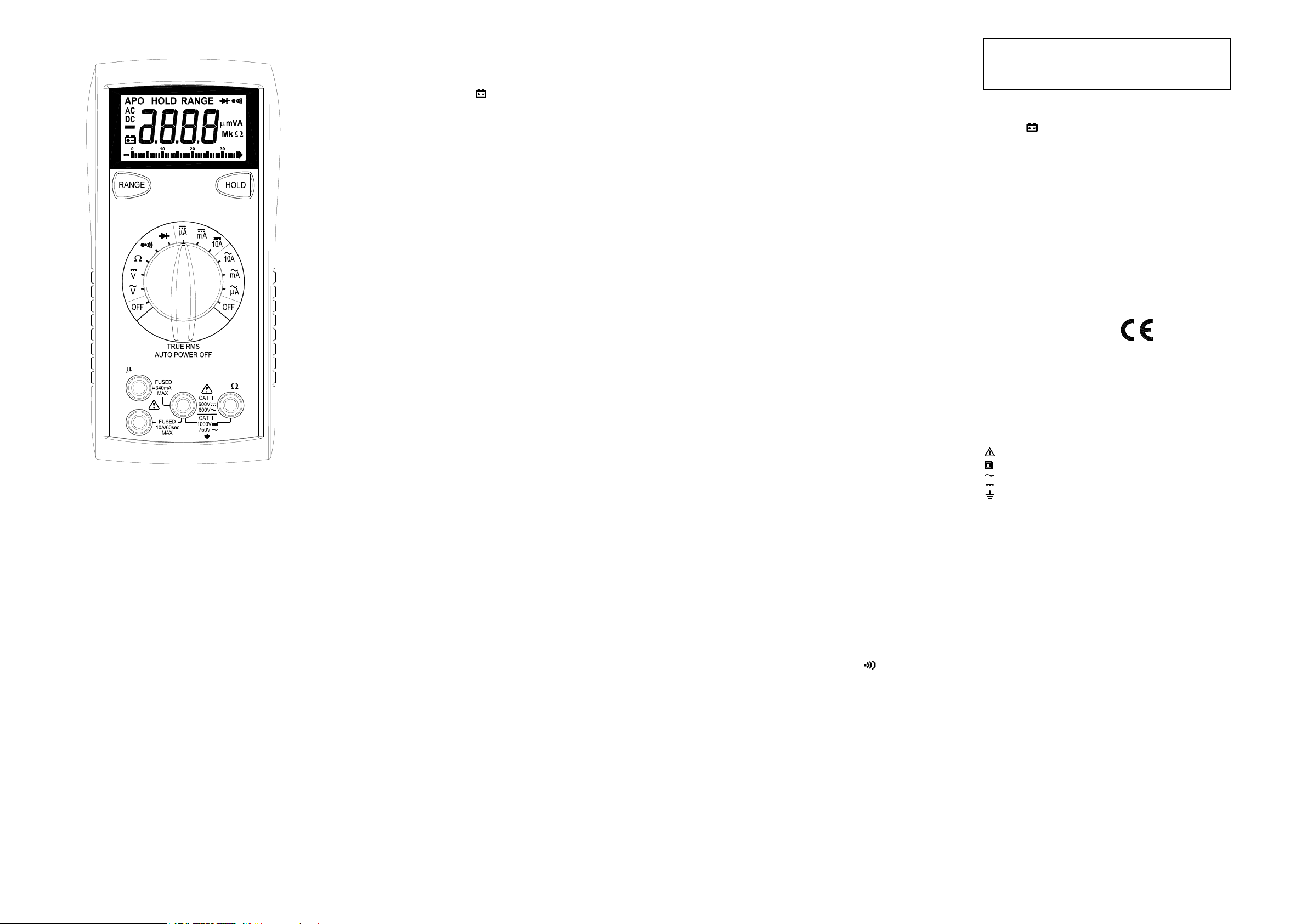
2708B
A mA
COM V
10A
PRESCRIPTIONS DE SECURITE
Les prescriptionsde sécurité ci dessous sont à suivre scrupuleusementafinde
garantir la sécurité de l’utilisateur:
N’utiliservotre appareilquedansle domained’utilisation défini dans ce manuel.
Dansle cas contraire les protections pourraient être endommagées.
Toujours tester votre appareil sur une tension connueavant de l’utiliserpourune
mesurede tension.
Ne pas utiliser votreappareilo uses cordonsvoussemblent endommagés.
Ne jamais vousmettre à la terrelorsque vous faitesdesmesures de tension.Ne
jamaistoucher des partiesmétalliques qui pourraientêtrereliées à la terre lors
d’unemesure. Dans la mesure du possible, isolez-vous de la terrepar des
chaussures, vêtements ou gants appropriés.
Pensezà couper le courant avant d’ouvrirun circuit ou d’intervenirsurcelui-ci.
Mêmeun faiblepotentiel peutêtredangereux.
Prenez toutes les précautions nécessaires lorsque vous intervenez sur des
tensions supérieures à 60VDC ou 30VAC eff.
Lorsque vous utilisezdes pointes de touche, ne jamais mettrelesdoigts au delà
des anneaux de garde.
Mesurer des tensions ou grandeurs au delà des limites de l’appareil peut
endommager les protections, endommager votre appareil et mettre en danger la
sécurité de l’utilisateur.Assurez vous de connaître les limites de votreappareil,
avantutilisation.
SPECIFICATIONS
Affichage: 3 3/4 digits (LCD)avec un affichage de3400 maximum
Bargraph: 34 segments avec12 mesures/s
Polarité:Automatique, avecindication du signe moins.
Dépassement: (OL)ou(-OL)est affiché.
Zéro:Automatique.
Indication de pile usée: le symbole
qu’il faut la remplacée.
Cadence de mesure: 2 fois/s (typique)
Arrêtautomatique:après environ 10 minutes.
Température de fonctionnement: 0℃ à 50℃ avecHR< 70%.
Température de stockage: -20℃ à 60℃, HR de 0 à 80%.
Précision: donnéeà 23℃ ±5℃, HR < 75%.
Coefficient de température: 0.1 x (précision) par ℃. (℃ < 18℃,et de 28℃ à
50℃).
Altitude: utilisation jusqu’à 2000m.
Alimentation:pile9 V type NEDA1604, JIS 006P, IEC 6F22.
Autonomie: 150 heurestypique.
Dimensions: 165mm(H)x 78mm (W) x 42.5mm (D).
Masse:environ 285g avec gaine
Accessoires: jeu de cordons, fusible de rechange, pile (9V) installée, manuel.
est affichélorsque la pile est usée et
" "
TENSIONS DC
Gammes: 340mV, 3.4V, 34V, 340V, 1000V
Résolution: 0.1mV
Précision: ±(1 . 0% r dg+ 2 dgt s)
Impédance d’entrée: 340mV:>100MΩ; 3.4V:10MΩ; 34V ~ 1000V:9.1MΩ
Protection: 1000VDC ou 750VAC eff.
TENSIONS AC (TRUE RMS AC)(50Hz – 1kHz)
Gammes: 3. 4V, 34V,340V, 750V
Résolution: 1mV
Précision: ±(2.0% + 8 dgts) 50 ~ 1kHz sur gamme3.4V, 34V
Impédance d’entrée: 3.4V: >10MΩ; 34V ~ 750V:9.1MΩ
Protection: 1000VDC ou 750VAC eff.
±( 2.0% + 8 dgts)50 ~ 500Hz sur 340V, 600V
COURANTS AC ET DC
Gammes: 340uA,3400uA, 34mA, 340mA,10A
Résolution: 0.1uA
Précision en DC:
±( 2.0% + 2 dgts)sur 340uAet340mA
±( 3.0% + 3 dgts)sur 10A
Précision en AC: (TRUE RMS AC) (50Hz ~ 500Hz)
±( 2.5% + 10 dgts)sur340uA et 340mA
±( 3.5% + 10 dgts)sur10A
Chute de tension: 0.2V sur gammes 340uA,34mA, 10A
2V sur gammes3400uA et 340mA
Protection: fusible F0.5A/500V (rapide céramique)
Fusible F10A/600V(rapide céramique)
Entrée 10A: 10Apendant 60 secondes maximum suivi d’unepériode sans
courant de 10minutes minimum
RESISTANCE
Gammes: 340Ω, 3.4kΩ, 34kΩ, 340kΩ, 3.4MΩ, 34MΩ
Résolution: 0.1Ω
Précision:
±(1.5%+ 4 dgts) sur gammes340Ωet 340kΩ
±(2.5%+4 dgts)surgamme 3.4MΩ
±(5.0%+ 5 dgts) sur gamme34MΩ
Tension en circuit ouvert: -0.45Vdc (-1.2Vdc surgamme 340Ω)
Protection: 500VDC ouAC eff.
TEST DIODE
Courant de test: 1.0mA(typique)
Précision: ±(3.0%+ 3 dgts)
Résolution: 10mV
Indication sonore: <0.25V
Tension en circuit ouvert: 3.0Vdctypique
Protection: 500VDC ouAC eff.
CONTINUITE
Indication sonore (buzzer): pour R< 35Ω
Temps de réponse: 500ms
Protection: 500VDC ouAC eff.
Alerte sonore pour cordons mal positionnés
Le multimètre dispose d’unealarme sonore si vous avezun cordonbranché
danslaborne mA ouA et si le commutateur estsurunemesure de tension. Dans
cecasvérifiez impérativement le branchement.
Fonction HOLD
Appuyer sur la touche [HOLD] pour figerl’affichage(HOLD). Un nouvel appui
permetunretour à unaffichage normal.
Utilisation en gammes manuelles
Le multimètre peut être utiliséengammes manuelles, ce qui peut être très
pratique pour certaines applications. Pourcela:
Appuyer sur la touche [RANGE]afinde figerlagamme.D’autres appuisur
[RANGE] feront défilerles gammesdans le sens croissant.Pourrepasseren
mode automatique,appuyer sur [RANGE] pendant plus de 2s
Mesures de tension
1. Brancher le cordon rouge à la borne ”VΩ” et le cordon noir à la borne ”COM”.
2. Positionner le commutateur sur la fonction appropriée DC ouAC.
3. Brancher les cordons sur votreapplication.
4. Lire le résultat sur l’afficheur LCD. La polarité est indiquée avec le signe (-)en
DC
Mesures de courant
1. Brancher le cordon rouge à la borne µA/mAou 10A,et le cordonnoirà la
borne”COM”.
2. Positionner le commutateur sur la gamme appropriée en DC ouAC.
3.Assurez-vousquelecircuit à mesurer est hors tensionet branchez vos
cordons en série dans ce circuit.
4. Mettresoustension et lire le courant sur l’afficheur LCD
Test Diode
1. Brancher le cordonrougeà la borne”VΩ” et le cordon noirà la borne ”COM”.
2. Positionner le commutateur sur “ “.
3.Assurez-vousqueledispositif à mesurer soit hors tension, afin de ne pas
fausserla mesure.
4. Testerla diodeà l’aidedes pointes de touché: le sens passant d’une diode
silicium fait apparaitre une tension de 0.6V (typique)
5. Une diodeouverte ou sens bloqué se traduirapar un affichage “OL”.Une
diodeencourt-circuit se traduiraparun affichage “000”ouproche de 0.
6. Remarque: une diodeouverte donne un affichage “OL” dans les 2 sens
7. Signalsonore pour une tension< 0.25V.
Test de continuité
1. Positionner le commutateur sur
2.Assurez-vousqueledispositif à mesurer soit hors tension, afin de ne pas
fausserla mesure.
3. Branchezlescordons à votre applicationoutester par contact avecles
pointes de touche. Le buzzer est actif pourR<35ohms.
Arrêt automatique
1.Après environ10 minutes.
2.Après un arrêt automatique, un appui sur une touchéou une remiseen
marcheparle commutateur permet une remise en fonctionnementnormal.
Inhibition de l’arrêt automatique:
Appuyer sur la touche (RANGE)à la mise en marche de l’appareil. L’arrêt
automatique est alors inhibé.
Remarque: le symbole “APO” n’apparait plus à l’affichage.
MAINTENANCE
ATTENTION- DANGER
maintenance – Risquedechocélectrique.
Remplacement de la pile
Votre multimètreutiliseunepile9V.(NEDA1604, IEC 6F22).Lorsque le symbole
" " apparait à l’affichage il faut remplacer la pile. Assurez-vous d’avoir
débranché les cordons.Dévisser le fond de boitieret remplacer la pile. Revisser
le fond de boitier.
F1 0.5A/500V,type céramiqueF (rapide), 6.35x32mm.
F2 10A/600V,typecéramique F (rapide), 6.35x25.4mm.
Attention : Ne remplacer les fusiblesqu’avec le même type.
Nettoyage
Nettoyer périodiquement avec un chiffondoux et humide. Ne pas utiliserde
solvants. Saleté et/ouhumidité au niveaudes douilles peuvent perturber les
mesures et donnerdes indicationsfausses.
Sécurité: IEC61010-1 (EN61010-1), CATII 1000V, CATIII600V, Class II, Degré
de pollution 2, utilisationà l’intérieur.
CATII / CAT III : se reporter aux normes pour la définitiondes catégories
d’installation
EMI: selon EN61326.
Symboles utilisés sur l’appareil:
Attention– Danger:se référer au manuel
Double isolement (ClasseII)
Courant alternatif
Courant continu
Terre
MISE EN OEUVRE
Avant toute mesure, assurez-vous d’avoir pris connaissance des Prescriptions
de Sécurité. Toujours vérifier que l’appareil et sescordons ne sont pas
endommagés. Si vous avez le moindredoute, ne pas effectuerdemesure.
Remplacement des fusibles
Si les mesuresdecourant ne fonctionnent pas, il faut vérifierl’état des fusibles
qui assurent la protectiondevotremultimètre.
les cordons. Dévisser le fond de boitieret vérifier les fusibles:
Assurez-vous d’avoirdébranché
Page 4

BEDIENUNGSANLEITUNG
DIGITAL-MULTIMETER
MODELL 2708B
2708B
A mA
COM V
10A
SAFETY INFORMATION
SICHERHEITSINFORMATIONEN
Um ein MaximumanpersönlicherSicherheit beim Betrieb dieses Multimeters zu
gewährleisten,bitteunbedingtfolgende Sicherheitshinweise beachten:
Das Gerätnurnachder in dieser BedienungsanleitungangegebenenSpezifikationverwenden.Ansonstenkönnen die im Messinstrument vorhandenen
Schutzmechanismen außer Kraftgesetzt sein.
TestenSie dasMultimeter zuerstmiteiner bekannten Spannung, bevor Sie es
dafürverwenden,das Vorhandensein von gefährlichen Spannungen zu überprüfen.
Das Multimeter nicht verwenden, wenn das Instrument oder die Prüfkabel Be-
schädigungenaufweisen oder wenn Sie den Eindruck haben, dass das Gerät
nicht ordnungsgemäß funktioniert.
Bei Durchführung elektrischer Messungen keine Erdungzumeigenen Körper
herstellen. Niemalsoffen liegende, blanke Kabel,Ausgänge,Anschlüsse, Vor-
richtungen, Halterungen berühren, um jeglichen Kontaktmit Erdpotential zu vermeiden. Sorgen Sie dafür, dass Ihr Körper von der Erde isoliert bleibt, indem Sie
trockene Kleidung,Gummischuhe,Gummimattenoderanderes zugelassenes
Isolierungsmaterial verwenden.
Schalten Sie denzuprüfendenSchaltkreiszuerststromlos, bevorSie ihn trennen,
ablöten oder unterbrechen.Auchgeringe Strommengen könnengefährlichsein.
SeienSie besonders vorsichtig, wennSie mit Spannungenarbeiten, die über60V
Gleichstrom oder 30 V Wechselstrom Effektivwert (rms)liegen. Spannungen in
dieser Höhe lösen elektrische Schlägeaus.
Beim Umgang mit denPrüfspitzendieFinger bitte stets hinterderAbschirmung
des Isoliergriffshalten.
DieMessung von Spannungen,die die Grenzwertedes Multimeters übersteigen,
kanndasGerätbeschädigenund den Bediener der GefahreinesStromschlags
aussetzen. BeachtenSie bittestets die auf der VorderseitedesGeräts
angegebenen Spannungsgrenzwerte.
SPECIFICATIONS
Display: 3¾-stellige Flüssigkristallanzeige(LCD)mitmax.3400 Zählimpulsen.
Analoge Balkenanzeige: 34 Segmentemit 12 Messungenpro Sekunde.
Polarität: Automatisch, positive Polaritätimplizit, negative wird angezeigt.
Bereichsüberschreitung: Anzeige von (OL) oder (-OL).
Null: Automatisch
Indikator bei schwacher Batteriespannung: SinktdieBatteriespannung unter
das Betriebsniveau, wird das Symbol
Messrate: Nennwert 2 Mal proSekunde.
Automatische Abschaltung: nach ca. 10 Minuten Inaktivität
Betriebsumgebung: 0℃ bis 50℃ bei einer relativen Feuchtigkeit < 70%.
Lagertemperatur: -20℃ bis 60℃, 0 bis 80% relativeFeuchtigkeit.
Genauigkeit: Angabengelten für 23℃ ±5℃ und einer relativen Feuchte< 75%.
Temperaturkoeffizient:0,1x (spezifizierteGenauigkeit)pro ℃. (℃ bis 18℃,28
℃ bis 50℃).
Maximale Höhenlage für den Betrieb: 2000 m.
Stromversorgung: 9-Volt-Bockbatterie, TypNEDA1604,JIS 006P, IEC6F22.
Batterielebensdauer: 150Stunden typischfürKohle-Zink.
Abmessungen: 165mm (H) x 78 mm (B) x 42,5mm (T).
Gewicht: ca. 285 g inkl.Holster.
Zubehör: 1 SatzPrüfkabel, 1 Stk.Ersatzsicherung, 9 V-Batterie(eingelegt)und
Bedienungsanleitung
angezeigt.
GLEICHSPANNUNG
Bereiche: 340 mV; 3,4 V;34V;340V; 1000 V.
Auflösung: 0,1 mV
Genauigkeit: ± (1% des Messwerts + 2 Stellen)
Eingangsimpedanz: 340 mV: >100 MΩ;3,4 V:10MΩ; 34 V ~ 1000V:9,1 MΩ
Überlastschutz: 1000 VDC oder 750 VACEffektivwert
WECHSELSPANNUNG (echte Effektivwerte)(50Hz –1kHz)
Bereiche: 3,4V, 34V, 340V, 750V
Auflösung: 1 mV
Genauigkeit: ± (2,0% des Messwerts+ 8 Stellen) 50 ~ 1kHz im3,4V,
34V-Bereich
Eingangsimpedanz: 3.4V: >10MΩ; 34V ~ 750V:9.1MΩ
Überlastschutz: 1000 VDC oder 750 VACEffektivwert
±( 2% des Messwerts + 8 Stellen) in den Bereichen340V, 600 V
STROM
Bereiche: 340uA,3400uA, 34mA, 340mA,10A
Auflösung: 0,1 µA
Genauigkeit Gleichstrom:
±( 2,0% des Messwerts+ 2 Stellen)in den Bereichen 340µAbis340mA
±( 3,0% des Messwerts+ 3 Stellen)im 10A-Bereich
Genauigkeit Wechselstrom: (echteEffektivwerte) (50Hz~ 500Hz)
±( 2,5% des Messwerts+ 10Stellen) in den Bereichen340µA bis 340mA
±( 3,5% des Messwerts+ 10Stellen) im 10A-Bereich
Spannungsbürde: 0,2Vin den Bereichen 340µA, 34mA,10A
2V in den Bereichen 3400µA, 340mA
Eingangsschutz: Flinke Keramiksicherung 0,5 A / 500 V
FlinkeKeramiksicherung 10A/ 600 V
10 A-Eingang: 10A für 60 SekundenMaximum gefolgt voneiner
Abkühlphase von 10 Minuten
WIDERSTAND
Bereiche: 340Ω, 3.4kΩ, 34kΩ, 340kΩ, 3.4MΩ, 34MΩ
Auflösung: 0,1Ω
Genauigkeit:
±( 1,5% des Messwerts+ 4 Stellen)in den Bereichen von 340Ωbis 340kΩ
±( 2,5% des Messwerts+ 4 Stellen)im 3,4MΩ-Bereich
±( 3,5% des Messwerts+ 5 Stellen)im 34MΩ-Bereich
Leerlaufspannung: -0,45 VDC (-1,2 VDC im Bereich 340Ω)
Überlastschutz: 500 VDC oderAC Effektivwert
DIODENTESTS
Prüfstrom: 1,0mA (ungefähr)
Genauigkeit: ±(3,0%desMesswerts+ 3 Stellen)
Auflösung: 10 mV
Signalton bei: <0,25 V
Leerlaufspannung: 3,0 VDC typisch
Überlastschutz: 500 VDC oderAC Effektivwert
DURCHGANGSPRÜFUNG
Signalton bei: unter 35 Ω.
Reaktionszeit: 500 ms
Überlastschutz: 500 VDC oderAC Effektivwert
FUNKTIONSBESCHREIBUNG / BETRIEB
BevorSieMessungen durchführen, lesenSiebittedenAbschnitt Sicherheitsinformationen.ÜberprüfenSiedasInstrument stetsaufBeschädigungen,
Schmutz(übermäßige Verschmutzungen,Fettusw.) und Defekte. Überprüfen
Sie die Isolierungder Messleitungen auf Risse oderAbnutzungserscheinungen.
Das Messgerät auf keinen Fall verwenden, wenn irgendwelche ungewöhnliche
Bedingungen vorliegen.
Akustisches Warnsignal bei falscher Buchsenbelegung
DasMessgerätverfügt über einenSummer,der den Benutzerwarnt, wennsich
die Messleitung in der Strombuchse befindet und das Gerät zur Spannungs-
messungeingestelltist. Dasist einzusätzlichesSicherheitsmerkmal für Ihre
Sicherheit und zum Schutz des Geräts.
Data Hold
DieTaste[HOLD] drücken um den Messwert auf dem Display “einzufrieren“,die
erneutes drücken wirddieMessung fortgesetzt.
Manuelle Bereichswahl – Taste [Range]
Das Gerätverfügt auch über einenModus zur manuellen Bereichswahl. Bei der
manuellen Bereichswahl wählenSiedenBereich und legen diesenfür die
Messungen des Gerätsfest.Sowählen Sie einen Bereichmanuell:
DieTaste[RANGE] drücken, um den ausgewählen Bereich festzulegen. Durch
nachfolgendesDrücken der Taste [RANGE]wirdnacheinander jederBereich
vom kleinsten zum größten Bereich ausgewählt. Halten Sie die Taste [RANGE]
für 2 Sekundengedrückt, um in den Modus derautomatischen Bereichswahl
zurückzukehren.
Spannungsmessungen
1.Die rote Messleitung an die Buchse„VΩ” unddie schwarzeMessleitungandie
Buchse„COM“ anschließen.
2.Den Funktions-/Bereichswahlschalterauf den gewünschtenSpannungstyp
(AC oderDC)unddenBereich einstellen. Ist dieGröße der Spannung nicht
bekannt, den Schalter aufdengrößtenBereicheinstellenunddann reduzieren,
bis ein zufriedenstellender Messwerterreicht ist.
3.Die Messleitungenandaszu messendeGerätoderden zu messenden Schaltkreisanschließen.
4.Für Gleichspannung(DC)wird für negative Polaritätdas Zeichen(-) angezeigt;
positive Polaritätist implizit.
Strommessungen
1.Die rote Messleitung an die Buchse „uA, mA oder10A”unddieschwarze
Messleitung an die Buchse „COM“ anschließen.
2.Den Funktions-/Bereichswahlschalterauf den BereichAC oderDCeinstellen.
3. Stromversorgung des zu messenden Schaltkreises abschalten und die
normale Leiterbahnöffnen, an der die Messungvorgenommenwerden soll.
Das Multimeter mit dem Schaltkreis in Reihe schalten.
4. Den Strom einschaltenunddenWert auf dem Display ablesen.
Widerstandsmessungen
1. Den Funktions-/Bereichswahlschalter auf den gewünschten
Widerstandsbereich einstellen.
2.Die Stromquelle des zu messendenGeräts abschalten.
3.Die rote Messleitung an die Buchse „VΩ“ und die schwarze Messleitung an
die Buchse „COM“ anschließen.
4.Die Messleitungen an die Messpunkteanschließen unddenWertvomDisplay
ablesen.
Diodentests
1.Die rote Messleitung an die Buchse „VΩ“ und die schwarze Messleitung an
die Buchse „COM“ anschließen.
2.Den Funktions-/Bereichswahlschalterauf die Position einstellen.
3.Die Stromquelle des zu messendenSchaltkreisesabschalten.Externe
Spannungenum die Komponenten herumführen zu fehlerhaften Messwerten.
4.Die Diode mit den Prüfspitzen berühren. Der Vorwärts-Spannungsabfall liegt
bei ca. 0,6 V (typischfüreineSilikon-Diode).
5.Prüfspitzenvertauschen. Wenn die Diodein Ordnung ist, wird „OL“ angezeigt.Ist dieDiodekurzgeschlossen, wird„000“oder eine andere Zahl
angezeigt.
6.Ist die Diode offen,wird„OL“ in beiden Richtungenangezeigt.
7. Signalton bei: unter 0,25 V.
Durchgangsprüfungen
1. Den Funktions-/Bereichswahlschalter auf die Position “ “ einstellen.
2.Die Stromversorgungdeszumessenden Schaltkreises abschalten. Externe
Spannungenum die Komponenten herumführen zu einem fehlerhaften
Messergebnis.
3.Die Messleitungen an die beiden Messpunkte anschließen, an denen der
Durchgang zu prüfen ist. Der Summerertönt, wenn derWiderstand unter
einemWert von ca. 35Ωliegt.
Automatische Abschaltung
1. AutomatischeAbschaltung: nach ca. 30 Minuten Inaktivität
2. Zum Start des Multimeters nach einer automatischenAbschaltung eine
beliebige Taste drückenundder Messwert bleibt aufdemDisplay
erhalten.
Automatische Abschaltung deaktivieren:
DieTaste[Range] gedrückthalten und den Funktions-/Bereichswahlschalter von
OFF zu einerbeliebigen Position drehen, um das Multimetereinzuschalten. Die
Funktion der automatischenAbschaltungist jetztdeaktiviert.
Hinweis:DerIndikator „APO“(Auto Power Off) wird nichtmehraufdemDisplay
angezeigt.
WARTUNG
WARNHINWEIS
Vor dem Austausch der Batterie oder der Sicherungen oder anderen
Wartungsarbeiten bitteunbedingt die Messleitungen abstecken!
Austausch der Batterie
DasGerät wird von einer 9 Voltgespeist (NEDA1604,IEC6F22). Wenn ein
Austausch erforderlich ist, erscheint auf dem Display das Symbol . Zum
Batteriewechselentfernen Sie aufderRückseitedes Gerätsdie dreiSchrau-
ben undnehmendasvordere Gehäuseteil ab. Entnehmen Sie dann die
Batterie aus dem UnterteildesGeräts.
Austausch von Sicherungen
WennkeineStrommessungenmöglich sind, überprüfen Sie, ob die Sicherungenfür den Überlastschutzdefekt sind. ZumAustauschderSicherungen
diedreiSchrauben auf der Rückseite des Gerätsentfernenund das vordere
Gehäuseteil abnehmen. Die SicherungF1 nurmit eineroriginalen,flinken
Keramik-Sicherung des Typs 0,5A/500V, 6,35 x 32 mm und die Sicherung
F2 nur mit eineroriginalen, flinkenKeramik-Sicherung des Typs10A/600 V,
6,35 x 25,4 mm ersetzen.
Reinigung
Gehäuse mit einem feuchtenTuch und mildem Reiniger abwischen. Keine
Scheuer- oderLösungsmittelverwenden.Schmutz oder Feuchtigkeit an den
Klemmenkann zu fehlerhaften Messergebnissen führen.
Sicherheit: Erfüllt die NormenIEC61010-1 (EN61010-1), CATII 1000V, CATIII
600V, KlasseII, Verschmutzungsgrad 2 zurVerwendung in
Innenräumen.
CATII: Gilt für Messungenan Schaltkreisen,die direkt mit eine
Niederspannungseinrichtung verbunden sind.
CAT III:Giltfür Messungen an Gerätenin Festinstallationen in Gebäuden.
EMV: Erfüllt die Norm EN61326.
Folgende Symbolefinden Sie aufdemGerät:
Vorsicht! BitteSicherheitshinweisein beiliegendenDokumenten beachten.
Gerätdurchgängiggeschützt durchdoppelte Isolierung (Klasse II)
Wechselstrom
Gleichstrom
Erde
Page 5

Limited Three-Year Warranty
B&K Precision warrants to the original purchaser that its products and the component parts
thereof, will be free from defects in workmanship and materials for a period of three years
date of purchase from an authorized B&K Precision distributor.
B&K Precision will, without charge, repair or replace, at its option, defective product or component
parts. Returned product must be accompanied by proof of the purchase date in the form of a
sales receipt.
To obtain warranty coverage in the U.S.A., this product must be registered by completing the
warranty registration form on www.bkprecision.com within fifteen (15) days of purchase.
Exclusions: This warranty does not apply in the event of misuse or abuse of the product
or as a result of unauthorized alterations or repairs. The warranty is void if the serial
number is altered, defaced or removed.
B&K Precision shall not be liable for any consequential damages, including without limitation
damages resulting from loss of use. Some states do not allow limitations of incidental or
consequential damages. So the above limitation or exclusion may not apply to you.
This warranty gives you specific rights and you may have other rights, which vary from state-tostate.
from
SERVICE INFORMATION
Warranty Service: Please go to our website,
button to obtain an RMA #. Return the product in the original packaging with proof of purchase to
the address below. Clearly state in writing the performance problem and return any leads, probes,
connectors and accessories that you are using with the device.
Non-Warranty Service: Please go to our website,
service/repair button to obtain an RMA #. Return the product in the original packaging to the
address below. Clearly state in writing the performance problem and return any leads, probes,
connectors and accessories that you are using with the device. Customers not on open account
must include payment in the form of a money order or credit card. For the most current repair
charges please visit
Return all merchandise to B&K Precision Corp. with pre-paid shipping. The flat-rate repair charge
for Non-Warranty Service does not include return shipping. Return shipping to locations in North
American is included for Warranty Service. For overnight shipments and non-North American
shipping fees please contact B&K Precision Corp.
Include with the returned instrument your complete return shipping address, contact
name, phone number and description of problem.
www.bkprecision.com and click on “service/repair”.
B&K Precision Corp.
22820 Savi Ranch Parkway
Yorba Linda, CA 92887
www.bkprecision.com
www.bkpreicsion.com & click on the service/repair
www.bkpreicsion.com & click on the
714-921-9095
 Loading...