

Page 1
OPERATING INSTRUCTIONS
MODEL 2706B
DIGITAL MULTIMETER
2706B
V
A
F
COM
SAFETY INFORMATION
The following safety information must be observedto ensure maximum personal
safetyduring the operationat thismeter:
Use the meteronlyasspecified in this manualorthe protection providedbythe
metermightbe impaired.
Test the meteron a knownvoltage before usingit to determineifhazardous
voltage is present.
Do not use the meter if the meteror test leadslookdamaged, or if you suspect
that themeteris notoperating properly.
Neverground yourselfwhentaking electricalmeasurements.Donot touch
exposed metal pipes, outlets, fixtures,etc., which might be at groundpotential.
Keepyourbody isolated from groundby using dry clothing,rubber shoes, rubber
mats,oranyapproved insulating material.
Turnoff power to the circuit undertestbefore cutting,unsoldering,orbreaking
the circuit.Small amountsofcurrent can be dangerous.
Use cautionwhen workingabove60Vdc or 30V ac rms.Suchvoltages pose a
shockhazard.
When usingtheprobes, keep your fingers behind the finger guardsonthe
probes.
Measuring voltagewhich exceeds the limitsofthemultimeter may damagethe
meterandexpose the operatorto a shock hazard. Alwaysrecognizethe meter
voltage limits as statedonthe frontofthemeter.
V
A
HzV
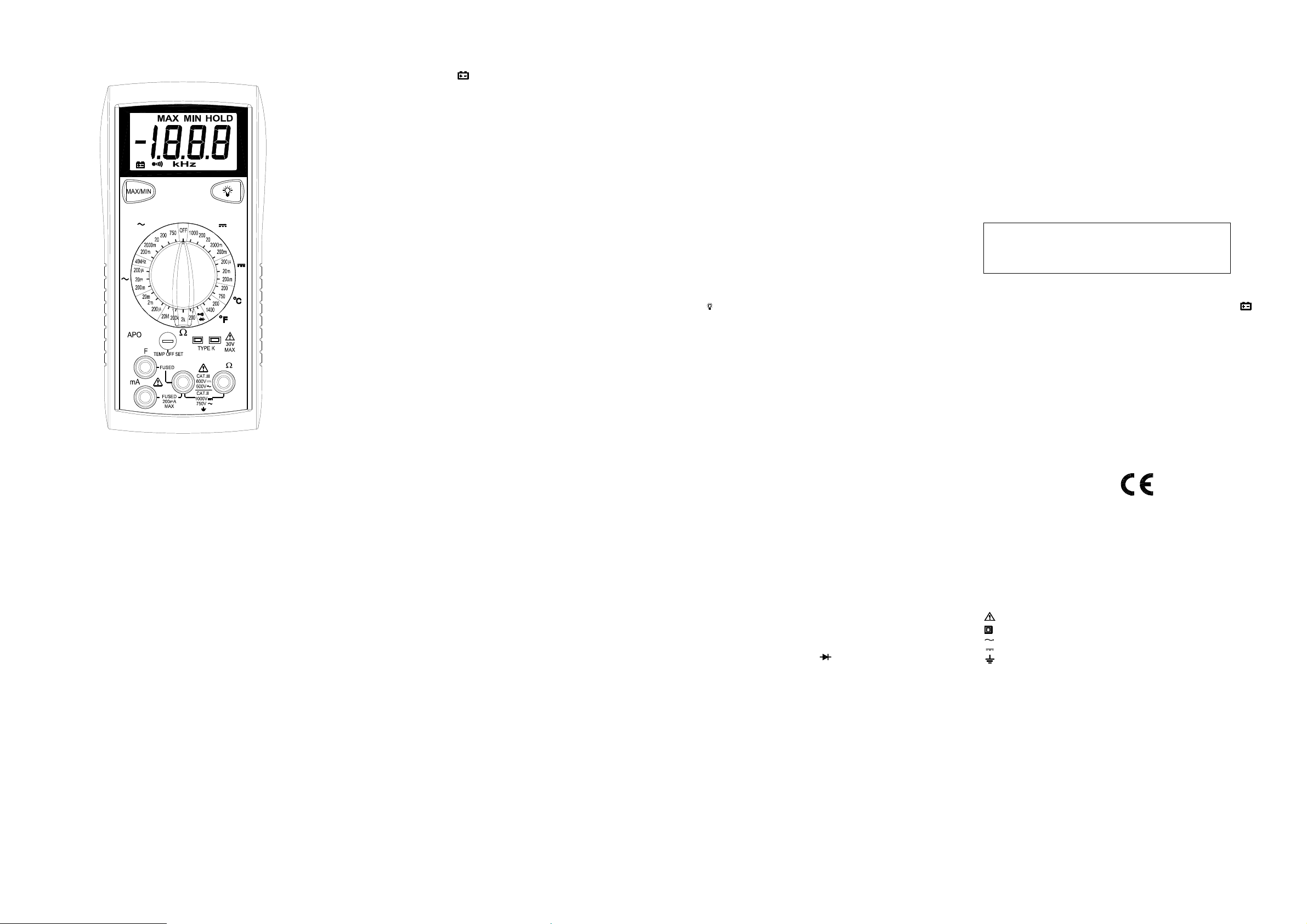
SPECIFICATIONS
Display: 3½ digitliquid crystaldisplay (LCD) with a maximum reading of 1999.
Polarity:Automatic, positiveimplied, negative polarityindication.
Overrange: (OL) or (-OL) is displayed.
Zero:Automatic.
Lowbattery indication:The
belowtheoperating level.
Measurement rate: 2.5 timespersecond, nominal.
Auto poweroff: Approx. 25 minutes.
Operating environment: 0℃ to 50℃ at < 70%relative humidity.
Storage temperature: -20℃ to 60℃,0 to 80% relativehumidity.
Accuracy: Statedaccuracy at 23℃±5℃, < 75% relative humidity.
Temperature Coefficient: 0.1 x (specifiedaccuracy) per ℃. (℃ to 18℃, 28℃ to
50℃).
Altitude: 6561.7 feet (2000m).
Power: Single standard 9-volt battery, NEDA1604, JIS 006P, IEC 6F22.
Battery life: 150 hours typicalwithcarbon-zinc.
Dimensions: 165mm(H) x78mm(W)x42.5mm(D).
Weight: Approx. 10.0 oz.(285g) includingholster.
Accessories: One set test leads,onespare fuse, 9V battery (installed),and
Operating Instructions.
is displayed when the batteryvoltage drops
" "
DC VOLTS
Ranges: 200mV,2000mV, 20V,200V,1000V
Resolution: 0.1mV
Accuracy: ± (0.5% rdg + 1 dgt)
Inputimpedance: 10MΩ
Overload protection: 1000VDCor750VACrms
600VDC/AC rms 15 seconds on 200mV range
AC VOLTS (50Hz- 500Hz)
Ranges: 200mV,2000mV,20V, 200V, 750V
Resolution: 0.1mV
Accuracy:
±( 1.2% rdg + 5dgts) on 200mV to 20V ranges
±( 2.0% rdg + 5 dgts) on 200V, 750Vranges
Inputimpedance: 10MΩ
Overload protection: 1000VDCor750VACrms
600VDC/AC rms 15 seconds on 200mV range
CURRENT
Ranges: 200uA, 20mA, 200mA
Resolution: 0.1uA
DC accuracy: ± ( 1.0%rdg+ 1 dgts)
AC accuracy: (50Hz ~ 500Hz)
±( 1.5% rdg + 5dgts)
Inputprotection: 0.25A/500V fast blowceramic fuse
RESISTANCE
Ranges: 200Ω, 2kΩ, 200kΩ,20MΩ
Resolution: 0.1Ω
Accuracy:
±( 1.0% rdg + 4 dgts) on 200Ωto 200kΩranges
±( 2.0% rdg+ 4 dgts) on 20MΩrange
Open circuit volts: 0.3Vdc (3.0Vdc on 200Ωrange)
Overload protection: 500VDC or AC rms
CONTINUITY
Audible indication: Less than 100Ω
Response time: 100ms
Overload protection: 500VDC or AC rms
DIODE TEST
Test current: Approx.1.0mA
Accuracy: ±(1.5% rdg + 3dgts)
Open circuit volts: 3.0Vdc typical
Overloadprotection:500VDC or AC rms
CAPACITANCE
Ranges: 200uF, 2mF, 20mF
Resolution: 0.1uF
Accuracy: ±(4% rdg + 10 dgts)
Test frequency: 21Hz
Test voltage: <3.0V
Inputprotection: 0.25A/500V fast blowceramic fuse
FREQUENCY (Autoranging)
Range: 10Hzto 40kHz
Resolution: 1Hz
Accuracy: ±(0.1% rdg+ 3 dgts)
Sensitivity: 3.5V RMS min
Overload protection: 500VDC or AC rms
TEMPERATURE
Ranges: -35℃ ~ 750℃,-30℉~ 1400℉
Resolution: 0.1℃, 0.1℉
Accuracy:
±(1.0% rdg + 1℃) 0℃ ~ 400℃
±(3.0% rdg + 3℃) -35℃ ~ 0℃, 400℃ ~750℃
±(1.0% rdg + 2℉) -4℉ ~ 750℉
±(3.0% rdg + 6℉) -30℉ ~ -4℉, 750℉ ~ 1400℉
Sensortype: K-type thermocouple
Overload protection: 60VDC or 30V AC rms
OPERATION
Beforetaking any measurements, readtheSafety InformationSection.Always
examine the instrumentfordamage, contamination (excessive dirt, grease,etc.)
and defects. Examine the test leadsforcracked or frayed insulation. If any
abnormal conditionsexist do not attempt to make any measurements.
MAX/MIN
PressMAX/MINonce begins recordingMINand MAX.
PressMAX/MINtoselectcurrent readingMIN or MAX.
Holddownfor2 secondstoexitMAX/MIN function.
Backlight
Pressthe button to activate the backlightforapproximate4.5minutes.
Voltage Measurements
1.Connect the red test lead to ”VΩ”jack and the blacktestleadtothe ”COM”
jack.
2.SettheFunction/Range switch to the desiredvoltage type (AC or DC) and
range. If magnitude of voltageis not known, setswitch to thehighest range
and reduceuntil a satisfactoryreading is obtained.
3.Connect the test leads to the deviceor circuitbeing measured.
4. For dc, a (-) sign is displayed for negativepolarity; positivepolarity is implied.
CurrentMeasurements
1.Connect the red test lead to the ”mA” jackandtheblacktestlead to the
"COM"jack.
2.SettheFunction/Range switch to the DC or AC ranges.
3.Remove power from the circuitunder test and open the normal circuitpath
wherethe measurement is to be taken. Connect the meter in series with the
circuit.
4.Apply power and read the value from the display.
Resistance and Continuity Measurements
1.SettheFunction/Range switch to the desiredresistance range or continuity
position.
2.Remove power from the equipment under test.
3.Connect the red test lead to the “ VΩ” jackandtheblacktestleadto
the ”COM” jack.
4.Touch the probes to the test points.In ohms,thevalue indicatedinthe display
is the measuredvalue of resistance. In continuity test,thebeeper sounds
continuously, if the resistanceislessthan 100Ω.
Diode Tests
1.Connect the red test lead to the “ VΩ” jackandtheblacktestleadto
the ”COM” jack.
2.SettheFunction/Range switch to the “ “ position.
3.Turn off powerto the circuitunder test. Externalvoltage across the
components causesinvalid readings.
4.Touch probes to the diode.A forward-voltagedrop is about 0.6V(typical for a
silicondiode).
5.Reverse probes.If the diodeis good, “OL”is displayed. If the diode is shorted,
“000” or another number is displayed.
6. If the diode is open,“OL” is displayed in both directions.
Capacitance Measurements
1.Set theFunction/Range switch to the desired F (capacitance) range.
2.Connect the red test lead to the “F “ jackandtheblack test lead to the
“COM“jack.
3.Touch the probes to the capacitor. Observepolarity whenmeasuring polarized
capacitors.
4.Read the capacitance directlyfromthedisplay.
5. Discharge the capacitorbefore taking capacitancemeasurements.
Frequency Measurements
1.Set theFunction/Range switch to the “40kHz”position.
2.Connect the red test lead to the“VΩ” jack and the black test lead to the
“COM“jack.
3.Connect the test leadsto the pointofmeasurement and readthefrequency
fromthe display.
Temperature Measurements
1.Set theFunction/Range switch to the desiredtemperaturerange: ℃, ℉
2. Remove leads and slidetheTemp switch to the right to close lead jacks.
3.PluganyK-typethermocouple directly into the meter to measure temperature.
4.Taketemperaturemeasurementusing the thermocouple probe and read the
temperature from the display.
Temp offset adjustment
The OFFSETcontrol is set at the factoryto allowforthevariations foundin
standard thermocouples. By adjusting the OFFSET control, you can optimize
measurement accuracy for a particularthermocouple at a particular
temperature.
MAINTENANCE
WARNING
Removetestleads before changing batteryor fuse or
performing any servicing.
Battery Replacement
Poweris supplied by a 9 volt battery. (NEDA1604, IEC 6F22).The
on the LCD displaywhen replacementisneeded. To replace the battery, remove
the threescrews from the back of the meter and lift off the frontcase.Remove
the battery from case bottom.
" "
appears
Fuse Replacement
If no currentandcapacitancemeasurements arepossible. Checkfora blown
overload protectionfuse. For access to fuses, removethethreescrews from the
back of the meterandliftoffthefront case.
Replace (F1/current measurements) (F2/capacitancemeasurements)only with
the original type 0.25A/500V,fastacting ceramic fuse.
Cleaning
Wipe the casewitha damp cloth andmilddetergent. Do not use abrasives or
solvents. Dirt or moisturein the terminalscan affect readings.
Safety: Conforms to IEC61010-1 (EN61010-1), CATII 1000V, CATIII600V, Class
II, Pollution degree2 Indooruse.
CATII: Is formeasurements performed on circuits directlyconnectedto the
low-voltageinstallation.
CAT III: Is for measurements performedinthebuilding installation.
EMC:Conforms to EN61326.
The symbolsused on this instrumentare:
Caution, refer to accompanying documents
Equipment protectedthroughoutbyDouble insulation(Class II)
Alternating current
Directcurrent
Ground
Page 2
INSTRUCCIONES DE FUNCIONAMIENTO
MODEL 2706B
MULTIMETRO DIGITAL
2706B
V
V
A
A
F
COM
INFORMACION DE SEGURIDAD
La siguiente información relativa a la seguridad deben ser observadas para
garantizar la máxima seguridad personal durante la operación en este
metro:
Utilice el medidor sólocomo se especificaenestemanualo de la protección
prevista en el metro podría verse afectada.
Prueba de que el medidor de voltaje en un conocido antes de usarlo para
determinar si está presente la tensión peligrosos.
No utilice el medidor si el medidorconductores de prueba o lucen dañados,
o si sospecha que el medidor no está funcionando correctamente.
Nunca terreno usted al tomar mediciones eléctricas. No toque las tuberías
de metal expuesto, puntos de venta, accesorios, etc, que podrían ser al
potencial de tierra. Mantenga su cuerpo aisladas de tierra mediante el uso
de ropa seca, zapatos de goma, alfombras de caucho, o cualquier material
aislante aprobado.
Apague la potencia al circuito bajo prueba antes de cortar, unsoldering, o
romper el circuito. Pequeñas cantidades de corriente puede ser peligroso.
Tenga cuidado cuando se trabaja por encima de 60V de CC o 30 V ac rms.
Esas tensiones plantean un peligro de choque.
Al utilizar las sondas, mantenga los dedos detrás del dedo de la mano de
los guardias de las sondas.
La medición de tensión que excede los límitesdela multímetro puededañar
el medidor y el operador de exponer a un peligro de choque. Siempre
reconocemos el medidor límites de tensión como se indica en la parte
frontal del medidor.
ESPECIFICACIONES
Pantalla:3 ½ dígitos, pantalla de cristal líquido (LCD) con un máximo de la
lectura de 1999.
Polaridad: Automática, positiva implícita, indicación de polaridad negativa.
Overrange: (OC) o (-OC) aparece en pantalla.
Cero: Automático.
Indicación de batería baja: El
cae por debajo del nivel de funcionamiento.
Tipo de Medición: 2,5 veces por segundo, nominal.
Apagado automático: aprox. 25 minutos.
Entorno operativo: 0°C a 50°C a <70% de humedad relativa.
Temperatura de almacenamiento: -20°C a 60°C, de 0 a80% de humedad
relativa.
aparece cuando el voltaje de la batería
" "
HzV
Precisión: Dicho de precisión a 23 ℃ ± 5 ℃, <75% de humedad relativa.
Coeficiente de temperatura: 0,1 x (exactitud especificada) por °C. (°C a
18°C, 28°C a 50°C).
Altitud: 6561,7 pies (2000m).
Potencia: El único estándar de la batería de 9 voltios, NEDA 1604, JIS
006P, IEC 6F22.
La duración de la batería: 150 horas típico con carbono-zinc.
Dimensiones: 165mm (H) x78mm (W) x42.5mm (D).
Peso: aprox. 10,0 oz (285g) incluyendo funda.
Accesorios: Un conjunto conductores de prueba, un fusible de repuesto,
batería de 9V (instalada), y Manual de instrucciones.
DC VOLTS
Rangos: 200mV, 2000mV, 20V, 200V, 1000 V
Resolución: 0.1mV
Precisión: ± (0,5% lectura + 1dgt)
Impedancia de entrada: 10M Ω
Protección de sobrecarga: 1000VCD o 750VCA rms
600VDC/AC rms 15 segundos en rango 200mV
VOLTS AC (50Hz - 500Hz)
Rangos: 200mV, 2000mV, 20V, 200V, 750 V
Resolución: 0.1mV
Precisión:
± (1,2% lectura + 5dgts) sobre rangos de 200mV a 20V
± (2,0% lectura + 5dgts) en 200V, 750V gamas
Impedancia de entrada: 10M Ω
Protección de sobrecarga: 600VCD o CA rms
600VDC/AC rms 15 segundos en rango 200mV
CORRIENTE
Rangos: 200uA, 20mA, 200mA
Resolución: 0.1uA
Precisión CD: ± (1,0% lectura + 1dgts)
Precisión CA: (50Hz ~ 500Hz)
± (1,5% lectura + 4dgts)
Entrada de protección: 0.25A/500V rápido golpe de fusibles de cerámica
RESISTENCIA
Rangos: 200Ω, 2kΩ, 200kΩ, 20MΩ
Resolución: 0.1Ω
Precisión:
± (1.0% lectura + 4dgts) sobre 200Ω a 200kΩrangos
± (2.0% lectura + 4dgts) en la gama 20MΩ
Voltios circuito abierto: 0.3Vcd (3.0Vcd gama de 200Ω)
Protección de sobrecarga: 500VCD o CA rms
CONTINUIDAD
Indicación audible: Menos de 100Ω
Tiempo de respuesta: 100ms
Protección de sobrecarga: 500VCD o CA rms
PRUEBA de DIODO
Corriente de prueba: aprox. 1.0mA
Precisión: ± (1.5% lectura + 3dgts)
Voltios circuito abierto: 3.0VCD típico
Protección de sobrecarga: 500VCD o CA rms
CAPACITANCE
Rangos: 200uF, 2mF, 20mF
Resolución: 0.1uF
Precisión: ± (4% lectura + 10dgts)
Prueba de frecuencia: 21Hz
Prueba de tensión: <3.0V
Entrada de protección: 0.25A/500V fusibles rápido de cerámica
FRECUENCIA (Autoranging)
Rango: 10Hz a 40kHz
Resolución: 1Hz
Precisión: ± (0.1% lectura + 3dgts)
Sensibilidad: 3.5V RMS min
Protección de sobrecarga: 500VCD o CA rms
TEMPERATURA
Rangos: -35°C ~ 750°C, -30°F ~ 1400°F
Resolución: 0.1°C, el 0.1°F
Precisión:
± (1.0% lectura + 1°C) 0°C ~ 400°C
± (3.0% lectura + 3°C) -35°C~ 0°C, 400°C ~ 750°C
± (1.0% lectura + 2°F) -4°F~ 750°F
± (3.0% lectura + 6°F) -30°F~ -4°F, 750°F ~ 1400°F
Tipo de sensor: K-tipo termopar
Protección de sobrecarga: 60VCD o 30 VCA rms
OPERACIÓN
Antes de tomar cualquier medida, lea la sección de Información sobre
Seguridad. Siempre examine el instrumento para para daños, la
contaminación (exceso de suciedad, grasa, etc) y defectos. Examine los
conductores de prueba para agrietados o rotos aislamiento. Si alguna de la
condicionesexiste no intente realizar las mediciones.
MAX / MIN
Oprime MAX / MIN una vez que comienza a grabar MIN y MAX.
Oprime MAX / MIN para seleccionar lectura actual MIN o MAX.
Mantenga oprimido durante 2 segundos para salir MAX / MIN función.
Luz de Fondo
Oprime el botón para activar la luz de fondo por aproximadamente 60
segundos.
Las mediciones de voltaje
1.Conecte el conductor rojo de prueba a la "V Ω" jack y el conductor negro
de prueba a la "COM" jack.
2. Seleccione la Función / Rango de cambio al tipo deseado de voltaje (CA
o CD) y la variedad. Si la magnitud de la tensión no es conocida,
sistemáticamente cambie a una escala mayor y reduzca el rango a una
manera satisfactoria hasta que se obtenga la lectura adecuada.
3. Conecte los conductores de prueba al dispositivo o circuito con que se
mide.
4. Para muestra polaridad negativa, un (-)se demuestra; polaridad positiva
es implicado.
Las mediciones de Corriente
1.Conecte el conductor rojo de prueba a la “mA” jack y el conductor negro
de prueba a la "COM" jack.
2. Seleccione la Función / Rango para cambiar de los rangos de CD a CA.
3. Elimine el poder del circuito bajo prueba y abra el circuito normal de ruta
donde la medición es quese deben tomar. Conecte el medidor en serie con
el circuito.
4. Aplicar y poder leer el valor de la exhibición.
Mediciones de Resistencia y Continuidad
1. Seleccione la Función / Rango cambiar a la resistencia deseada gama.
2. Elimine el poder de los equipos bajo prueba.
3. Conecte el conductor rojo de prueba a la "V Ω" jack y el conductor negro
de prueba a la "COM" jack.
4. Conecte los conductores de prueba a los puntos de medición y lea el
valor de la exhibición.
Es el valor medido de la resistencia. En la continuidad de prueba, el
zumbador suena continuamente, si la resistencia es inferior a 100 Ω.
Prueba de Diodo
1.Conecte el conductor rojo de prueba a la "V Ω" jack y el conductor negro
de prueba a la "COM" jack.
2. Seleccione la Función / Rango a al posición de "(diode symbol)".
3. Elimine el poder de los equipos bajo prueba. Exteriores voltaje a través
de los componentes causas lecturas no válidas.
4. Toque las sondas al diodo. Una caída de tensión hacia adelante-es de
unos 0.6V (típico para un diodo de silicio).
5. Reverse sondas. Si el diodo es bueno, el "OL" se muestra. Si el diodo
está e n cortocircuito, "000" u otro número aparece en la pantalla.
6. Si el diodo está abierto, el "OL" se muestra en ambas direcciones.
Mediciones de Capacitancia
1. Seleccione la Función / Rango a el rango de capacitancia deseado.
2. Conecte el conductorrojo de prueba a la "F" jack y el conductor negrode
prueba a la "COM" jack.
3. Toque las sondas al condensador. Observe polaridad en la medición de
capacitores polarizados.
4. Leer la capacitancia directamente de la pantalla.
5. Aprobación de la gestión en el condensador antes de tomar mediciones
de la capacitancia.
Las mediciones de frecuencia
1. Establezca la Función / Rango cambiar a la "40kHz" posición.
2. Conecte el conductor de prueba rojo a la "V Ω" jack y el conductor negro
de prueba a la "COM" jack.
3. Conectar los conductores de prueba al punto de medida y lea la
frecuencia de la pantalla.
Las mediciones de temperatura
1. Establezca la Función / Rango a la gama de temperatura deseada: °C, °F
2. Elimine el conductor de Temperatura y deslice el interruptor a la derecha
para cerrar los insumos.
3. Conecte cualquier tipo termopar K directamente en el metro para medir la
temperatura.
4. Tome la medición de la temperatura utilizando la sonda termopar y leer la
temperatura de la pantalla.
Ajuste de compensar para Temperatura
El OFFSET control se fija en la fábrica para permitir las variaciones
encontradas en termopares estándar. Al ajustar el OFFSET de control,
puede optimizar la exactitud de medición para un termopar a una
temperatura particular.
MANTENIMIENTO
ADVERTENCIA
Eliminar conductores de prueba antes de cambiar la batería o
fusible o realización de cualquier servicio.
Reemplazo de baterías
La potencia es suministrada por una batería de 9 voltios. (NEDA 1604, IEC
6F22). El
sustituir la batería, quitar los tres tornillos de la parte posterior del medidor y el
ascensor frente a la parte delantera caso. Extraiga la batería caso de la parte
inferior.
aparece en pantalla, cuando el reemplazo es necesario. Para
" "
Reemplazo de fusibles
Si no hay capacidad actual y las mediciones son posibles. Por favor,
soplado un fusible de protección contra sobrecarga. Para el acceso a los
fusibles, retire los tres tornillos de la parte posterior delmedidoryelLevante
la parte delantera.
Reemplazar(F1/mediciones de corriente)(F2/ mediciones de capacitancia)
sólo con el tipo original 0.25A/500V, actuando rápido de fusibles de
cerámica.
Limpieza
Limpie el caso con un paño húmedo y detergente suave. No utilice
productos abrasivos o disolventes. La humedad o la suciedad en los
terminales pueden afectar a las lecturas.
Seguridad: Cumple con IEC61010-1 (EN61010-1), CATII 1000V, CATIII
600 V, ClassII, grado de contaminación 2 Salas de uso.
CATII: Es para las mediciones realizadas en los circuitos conectados
directamente a la instalación de baja tensión.
CAT III: Es para las mediciones realizadas en la construcción de la
instalación.
EMC: Cumple con EN61326.
Los símbolos utilizados en este instrumento son:
Precaución, refiérase a los documentosque la acompañan
Equipo protegido en todo momento por doble aislamiento (clase II)
Corriente alterna
Corriente
Ground
Page 3

Manuel d’utilisation
Il est impératif de débrancher les cordons avant toute opération de
Modèle 2706B
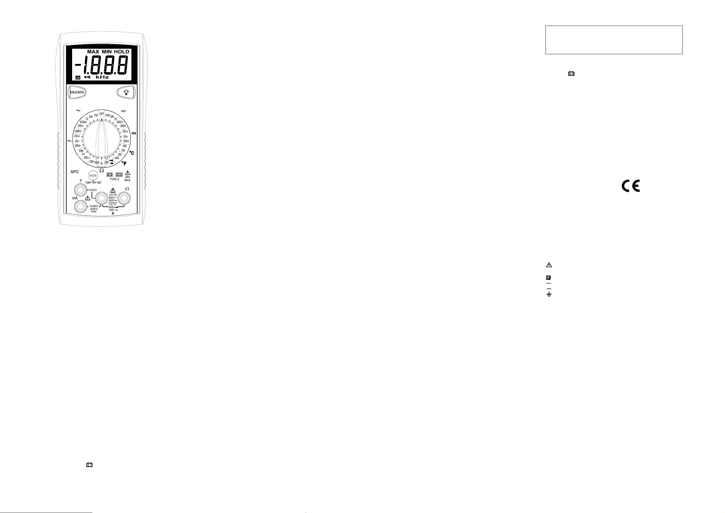
Multimètre Numérique 2000 points
2706B
V
A
F
COM
PRESCRIPTIONS DE SECURITE
Les prescriptionsde sécurité ci dessous sont à suivre scrupuleusementafinde
garantir la sécurité de l’utilisateur:
N’utiliser votre appareil que dans le domaine d’utilisation défini dansce manuel.
Dansle cas contraire les protections pourraient être endommagées.
Toujours tester votre appareil sur une tension connueavant de l’utiliserpourune
mesuredetension.
Ne pas utiliservotre appareilouses cordons vous semblent endommagés.
Ne jamais vousmettre à la terrelorsque vous faitesdesmesures de tension.Ne
jamaistoucher des partiesmétalliques quipourraientêtrereliées à la terrelors
d’unemesure. Dans la mesure du possible, isolez-vous de la terrepar des
chaussures, vêtements ou gants appropriés.
Pensezà couperle courant avant d’ouvriruncircuit ou d’intervenirsurcelui-ci.
Mêmeun faiblepotentiel peutêtredangereux.
Prenez toutes les précautions nécessaires lorsquevousintervenezsur des
tensions supérieures à 60VDC ou 30VACeff.
Lorsque vous utilisezdes pointes de touche, ne jamais mettrelesdoigts au delà
des anneaux de garde.
Mesurer des tensions ou grandeurs au delà des limites de l’appareil peut
endommager les protections, endommager votre appareil et mettre en danger la
sécurité de l’utilisateur.Assurez vous de connaître les limites de votre appareil,
avantutilisation.
V
A
HzV
SPECIFICATIONS
Affichage: 3½ digits(LCD) avec un affichagede 1999 maximum
Polarité:Automatique, avecindication du signe moins.
Dépassement: (OL)ou(-OL)estaffiché.
Zéro:Automatique.
Indication de pile usée: le symbole
qu’ilfautlaremplacée.
Cadence de mesure: 2.5 fois/s (typique)
Arrêtautomatique:après environ 25 minutes.
Température de fonctionnement: 0℃ à 50℃ avecHR< 70%.
Température de stockage: -20℃ à 60℃, HR de 0 à 80%.
Précision: donnéeà 23℃ ±5℃, HR < 75%.
Coefficient de température: 0.1 x (précision) par ℃. (℃ < 18℃,et de 28℃ à
50℃).
Altitude: utilisation jusqu’à 2000m.
Alimentation:pile9 V type NEDA1604, JIS 006P, IEC 6F22.
Autonomie: 150 heurestypique.
Dimensions: 165mm(H)x 78mm (W) x 42.5mm (D).
Masse:environ 285g avec gaine
Accessoires: jeu de cordons, fusible de rechange, pile (9V) installée, manuel.
est affichélorsque la pile est usée et
" "
TENSION DC
Gammes: 200mV, 2000mV, 20V, 200V,1000V
Résolution: 0.1mV
Précision: ± (0.5% + 1 dgt)
Impédance d’entrée: 10MΩ
Protection: 1000VDCou 750VAC eff.
600VDC/AC eff. limitéà 15 secondes sur lagamme200mV
TENSIONAC (50Hz- 500Hz)
Gammes: 200mV, 2000mV, 20V,200V,750V
Résolution: 0.1mV
Précision:
±( 1.2% + 5 dgts)de 200mV à 20V
±( 2.0% +5 dgts) sur 200V, 750V
Impédance d’entrée: 10MΩ
Protection: 1000VDCou 750VAC eff.
600VDC/AC eff. limitéà 15 secondes sur lagamme200mV
COURANTSAC et DC
Gammes: 200uA,20mA,200mA
Résolution: 0.1uA
Précision en DC: ±(1.0% + 1 dgts)
Précision en AC: (50Hz~ 500Hz)
±( 1.5% + 5 dgts)
Protection: fusibleF0.25A/500Vtype céramique
RESISTANCE
Gammes: 200Ω, 2kΩ, 200kΩ, 20MΩ
Résolution: 0.1Ω
Précision:
±( 1.0% + 4 dgts)de 200Ωà 200kΩ
±( 2.0% +4 dgts) sur 20MΩ
Tension en circuitouvert: 0.3Vdc (3.0Vdcsur 200Ω)
Protection: 500VDCou AC eff.
TEST DE CONTINUITE
Indication sonore:pourR<100Ω(typique)
Temps de réponse: 100ms
Protection: 500VDC ou AC eff.
TEST DIODE
Courant de test: Approx.1.0mA
Précision: ±(1.5% + 3dgts)
Tension en circuitouvert: 3.0Vdc typical
Protection: 500VDC ou AC eff.
Mesure de capacité
Gammes: 200uF, 2mF, 20mF
Résolution: 0.1uF
Précision: ±(4% + 10 dgts)
Fréquence de test: 21Hz
Tension de test: <3.0V
Protection: fusibleF0.25A/500V(céramique,rapide)
Mesure de fréquence (gammes automatiques)
Gamme: 10Hzà 40kHz
Résolution: 1Hz
Précision: ±(0.1% + 3 dgts)
Sensibilité: 3.5V eff. minimum
Protection: 500VDC ou AC eff.
TEMPERATURE
Gammes: -35℃ ~ 750℃,-30℉~ 1400℉
Résolution: 0.1℃, 0.1℉
Précision:
±(1.0% + 1℃) 0℃ ~ 400℃
±(3.0% + 3℃)-35℃ ~ 0℃, 400℃ ~ 750℃
±(1.0% + 2℉) -4℉ ~ 750℉
±(3.0% + 6℉) -30℉ ~ -4℉, 750℉ ~ 1400℉
Type de capteur: thermocouple typeK
Protection: 60VDCou 30VAC eff.
MISEEN OEUVRE
Avant toute mesure, assurez-vous d’avoirprisconnaissancedes Prescriptions
de Sécurité. Toujours vérifier que l’appareil et sescordons ne sont pas
endommagés. Si vous avezle moindredoute, ne pas effectuerdemesure.
Fonction MAX/MIN
Appuyer sur MAX/MIN pour débuter l’enregistrement desMINetMAX.
Appuyer sur MAX/MIN pour passer de la mesureen cours,puisauMINetau
MAX.
Appuyer plus de 2s poursortir de la fonction MAX/MIN.
Rétro-éclairage de l’afficheur
Appuyer sur pour mettre en fonctionle retro-éclairage durant 4.5minutes.
Mesures de tension
1. Brancher le cordon rouge à la borne ”VΩ” et le cordon noirà la borne ”COM”.
2. Positionner le commutateur sur la gamme appropriée en DC ouAC. Toujours
commencer parlagammela plus élevéesivous ne connaissezpas la valeurà
mesurer.
3. Brancher les cordons sur votreapplication.
4. Lire le résultat sur l’afficheur LCD. La polarité est indiquée avec le signe (-)en
DC
Mesures de courant
1. Brancher le cordon rougeà la borne ”mA” et le cordon noirà la borne ”COM”.
2. Positionner le commutateur sur la gamme appropriée en DC ouAC.
3.Assurez-vousquelecircuit à mesurer est hors tension et branchez vos
cordons en série dans ce circuit.
4. Mettresoustensionet lirele courant sur l’afficheur LCD
Mesures de résistance et continuité
1. Positionner le commutateur rotatif sur la gammeappropriéede résistance ou
continuité.
2.Assurez-vousqueledispositif à mesurer soit hors tension.
3. Brancher le cordon rougeà la borne”VΩ” et le cordon noirà la borne”COM”.
4. Branchez les cordons à votre application ou tester par contact avec les
pointes de touche. En test de continuité,lebuzzer est actif pour R<100 ohms.
Test Diode
1. Brancher le cordon rouge à la borne”VΩ” et le cordon noir à la borne ”COM”.
2. Positionner le commutateur sur “ “ .
3.Assurez-vousqueledispositif à mesurer soit hors tension, afin de ne pas
fausserla mesure.
4. Testerla diodeà l’aidedes pointes de touché: le sens passantd’unediode
silicium fait apparaitre une tension de 0.6V (typique)
5. Une diodeouverte ou sens bloqué se traduiraparun affichage “OL”.Une
diodeencourt-circuit se traduiraparunaffichage “000”ouproche de 0.
6. Remarque: une diode ouvertedonne un affichage“OL” dans les 2 sens
Mesures de capacité
1.Positionnerlecommutateursurla gammedésirée (marquage F)
2. Brancher le cordon rouge à la borne “F “ et le cordonnoiràla borne”COM”.
3. Se brancherauxbornes du condensateur à l’aide des pointes de touche
4.Lire la valeur directement sur l’afficheur
5. Ne faire les mesuresquesurdescondensateurs déchargés.
Mesures de fréquence
1. Positionner le commutateur sur ”40kHz”
2.Brancherle cordonrouge à la borne”VΩ” et le cordon noirà la borne ”COM”.
3. Brancher sur votre application et lirelafréquence sur l’afficheur. Le
changement de gamme est automatique.
Mesures de température
1.Placer le commutateur sur : ℃, ℉ et sur la gammeappropriée
2. Enleverles cordons de mesure.
3. Brancher directement le thermocouple de typeK dans les bornes d’entrée.
4.Lire la temperaturesurl’afficheur.
Ajustage de l’offset de température
Pourprendre en compte les dispersions des thermocouples, il est possible
d’ajuster la température à l’aide du potentiomètre en face avantdumultimètre.
Pouravoirunemesureexacte, il est impératifd’avoir une température de
référence afin de réalisercetajustage.
MAINTENANCE
ATTENTION- DANGER
maintenance – Risquedechocélectrique.
Remplacement de la pile
Votre multimètreutiliseunepile9V.(NEDA1604,IEC 6F22). Lorsque le symbole
" "apparaità l’affichage il faut remplacer la pile.Assurez-vous d’avoir
débranché les cordons.Dévisser le fond de boitier et remplacerla pile.Revisser
le fond de boitier.
Remplacement des fusibles
Assurez-vous d’avoirdébranché les cordons.Dévisser le fond de boitieret
vérifier les fusibles
F1 et F2 sont du même type : F0.25A/500V, fusible rapide, type céramique
:
Nettoyage
Nettoyer périodiquement avec un chiffondoux et humide. Ne pas utiliserde
solvants. Saleté et/ouhumidité au niveaudes douilles peuvent perturber les
mesures et donner des indications fausses.
Sécurité: IEC61010-1 (EN61010-1), CATII 1000V, CATIII 600V, Class II, Degré
de pollution 2, utilisationà l’intérieur.
CATII / CATIII : se reporter aux normes pour la définitiondescatégories
d’installation
EMI: selonEN61326.
Symboles utiliséssurl’appareil:
Attention– Danger:se référer au manuel
Double isolement (ClasseII)
Courant alternatif
Courant continu
Terre
Page 4

BEDIENUNGSANLEITUNG
DIGITAL-MULTIMETER
MODELL 2706B
2706B
V
A
F
COM
SICHERHEITSINFORMATIONEN
Um ein MaximumanpersönlicherSicherheit beim Betrieb dieses Multimeters zu
gewährleisten,bitteunbedingtfolgende Sicherheitshinweise beachten:
Das Gerätnurnachder in dieserBedienungsanleitungangegebenenSpezifikationverwenden.Ansonstenkönnen die im Messinstrument vorhandenen
Schutzmechanismen außer Kraftgesetzt sein.
TestenSie dasMultimeter zuerstmiteiner bekanntenSpannung,bevorSiees
dafürverwenden,das Vorhandensein von gefährlichen Spannungen zu überprüfen.
Das Multimeter nicht verwenden, wenn das Instrument oder die Prüfkabel Beschädigungenaufweisen oder wenn Sie den Eindruck haben, dass das Gerät
nichtordnungsgemäß funktioniert.
Bei Durchführung elektrischer Messungen keine Erdungzumeigenen Körper
herstellen. Niemalsoffen liegende, blanke Kabel,Ausgänge,Anschlüsse, Vorrichtungen, Halterungen berühren, um jeglichen Kontakt mit Erdpotential zu vermeiden. Sorgen Sie dafür, dass Ihr Körper von der Erde isoliert bleibt, indem Sie
trockene Kleidung,Gummischuhe,Gummimattenoderanderes zugelassenes
Isolierungsmaterial verwenden.
Schalten Sie denzuprüfendenSchaltkreiszuerst stromlos, bevorSie ihn trennen,
ablöten oder unterbrechen.Auchgeringe Strommengen könnengefährlich sein.
SeienSie besonders vorsichtig, wennSie mit Spannungenarbeiten,die über60V
Gleichstrom oder 30 V Wechselstrom Effektivwert (rms)liegen. Spannungen in
dieserHöhe lösen elektrische Schlägeaus.
Beim Umgang mit denPrüfspitzendieFinger bitte stets hinterderAbschirmung
des Isoliergriffshalten.
DieMessung von Spannungen,die dieGrenzwertedesMultimetersübersteigen,
kanndasGerätbeschädigenunddenBediener der Gefahr eines Stromschlags
aussetzen. BeachtenSiebittestets die auf der VorderseitedesGeräts
angegebenen Spannungsgrenzwerte.
V
A
HzV
TECHNISCHE DATEN
Display: 3½ -stellige Flüssigkristallanzeige(LCD)mit max.1999 Zählimpulsen.
Polarität: Automatisch, positive Polarität implizit,negative wird angezeigt.
Bereichsüberschreitung: Anzeigevon(OL)oder (-OL).
Null:Automatisch
Indikator bei schwacherBatteriespannung: SinktdieBatteriespannung unter
das Betriebsniveau, wird das Symbol
Messrate: Nennwert 2,5 Mal pro Sekunde.
AutomatischeAbschaltung: nach ca. 25Minuten Inaktivität
Betriebsumgebung: 0℃ bis 50℃ bei einerrelativen Feuchtigkeit < 70%.
Lagertemperatur: -20℃ bis 60℃, 0 bis 80% relative Feuchtigkeit.
Genauigkeit:Angaben geltenfür 23℃ ±5℃ und einer relativen Feuchte< 75%.
Temperaturkoeffizient:0,1x (spezifizierteGenauigkeit)pro ℃. (℃ bis 18℃,28
℃ bis 50℃).
Maximale Höhenlagefürden Betrieb: 2000m.
Stromversorgung: 9-Volt-Bockbatterie, TypNEDA1604, JIS 006P, IEC6F22.
Batterielebensdauer: 150 Stundentypisch für Kohle-Zink.
Abmessungen: 165 mm (H) x 78 mm (B) x 42,5 mm (T).
Gewicht: ca. 285 g inkl.Holster.
Zubehör: 1 SatzPrüfkabel, 1 Stk.Ersatzsicherung, 9 V-Batterie(eingelegt)und
Bedienungsanleitung.
GLEICHSPANNUNG
Bereiche: 200mV; 2000mV; 20V;200V; 1000 V.
Auflösung: 0,1 mV
Genauigkeit: ± (0,5% des Messwerts + 1 Stelle)
Eingangsimpedanz: 10MΩ
Überlastschutz: 1000 VDC oder750VAC Effektivwert
600VDC/ACrms für 15 Sekunden im 200mV Bereich
WECHSELSPANNUNG (50 Hz - 500 Hz)
Bereiche: 200mV,2000mV, 20V, 200V, 750V
Auflösung: 0,1 mV
Genauigkeit:
±( 1,2% des Messwerts+5 Stellen)indenBereichen 200mV bis 20V
±( 2,0% des Messwerts+5 Stellen)im200Vund750V-Bereich
Eingangsimpedanz: 10MΩ
Überlastschutz: 1000 VDC oder750VAC Effektivwert
600VDC/ACrms für 15 Sekunden im 200mV Bereich
STROM
Bereiche: 200uA, 20mA, 200mA
Auflösung: 0,1 µA
Genauigkeit Gleichstrom:
±( 1,0% des Messwerts+1 Stelle)
Genauigkeit Wechselstrom: (50Hz ~ 500 Hz)
±( 1,5% des Messwerts+5 Stellen)
Eingangsschutz: FlinkeKeramiksicherung 0,25A/ 500V
WIDERSTAND
Bereiche: 200Ω, 2kΩ, 200kΩ, 20MΩ
Auflösung: 0,1 Ω
Genauigkeit:
±( 1,0% des Messwerts+4 Stellen)indenBereichen von 200Ωbis 200kΩ
±( 2,0% des Messwerts+4 Stellen)im20MΩ-Bereich
Leerlaufspannung: 0,3VDC ( 3 DC im Bereich 200Ω)
Überlastschutz: 500 VDC oderAC Effektivwert
DURCHGANGSPRÜFUNG
Signalton bei: unter 100Ω.
Reaktionszeit: 100ms
Überlastschutz: 500 VDC oderAC Effektivwert
DIODENTESTS
Prüfstrom: 1,0 mA (ungefähr)
Genauigkeit: ± ( 1,5% des Messwerts + 3 Stellen)
Leerlaufspannung: 3,0VDCtypisch
Überlastschutz: 500 VDC oderAC Effektivwert
KAPAZITÄT
Bereiche: 200uF, 2mF,20mF
Auflösung: 0.1uF
Genauigkeit:
±( 4,0% des Messwerts+10Stellen)
Test-Frequenz: 21Hz
Test-Spannung:<0,3V
Eingangsschutz: FlinkeKeramiksicherung 0,25A/ 500V
angezeigt.
FREQUENZ (automatische Bereichswahl)
Bereiche: 10Hz bis 40kHz
Auflösung: 1Hz
Genauigkeit:±( 0,1% des Messwerts + 3 Stellen)
Empfindlichkeit: 3,5VRMSmin
Überlastschutz: 500 VDC oderAC Effektivwert
TEMPERATURMESSUNG
Bereiche: -35℃ ~ 750℃,-30℉~ 1400℉
Auflösung: 0.1℃, 0.1℉
Genauigkeit:
±(1.0% rdg + 1℃) 0℃ ~ 400℃
±(3.0% rdg + 3℃) -35℃ ~ 0℃, 400℃ ~ 750℃
±(1.0% rdg + 2℉) -4℉ ~ 750℉
±(3.0% rdg + 6℉) -30℉ ~ -4℉, 750℉ ~ 1400℉
SensorTyp: K-type Thermoelement
Überlastschutz::60VDC oder30V AC rms
FUNKTIONSBESCHREIBUNG / BETRIEB
BevorSieMessungen durchführen, lesenSiebittedenAbschnittSicherheitsinformationen.ÜberprüfenSiedasInstrument stetsaufBeschädigungen,
Schmutz(übermäßige Verschmutzungen,Fettusw.) und Defekte. Überprüfen
Sie die Isolierungder Messleitungen auf Risse oderAbnutzungserscheinungen.
Das Messgerät auf keinen Fall verwenden, wenn irgendwelche ungewöhnliche
Bedingungen vorliegen.
MAX / MIN
Bei „MAX“wirdder MaximalwertderMessung angezeigt. Bei „MIN“ ist der
MinimumwertderMessungen abzulesen. "MAX/MIN"erscheint auf dem LCD
und blinkt, umdenWertanzuzeigen,dergerade gemessenwird. Nach
Beendigung der Messungdrücken Sie die MAX/MIN-Taste länger als 2
Sekunden, um den Modus zu verlassen.
Hintergrundbeleuchtung – Taste
Drücken der Taste aktiviert für ca. 4,5 Sekunden die Hintergrundbeleuchtung
Spannungsmessungen
1.Die rote Messleitung an die Buchse„VΩ” unddieschwarzeMessleitungandie
Buchse„COM“ anschließen.
2.Den Funktions-/BereichswahlschalteraufdengewünschtenSpannungstyp
(AC oderDC)unddenBereich einstellen. Ist dieGröße der Spannung nicht
bekannt, den Schalter aufdengrößtenBereicheinstellenunddann reduzieren,
bis ein zufriedenstellender Messwerterreicht ist.
3.Die Messleitungenandaszu messendeGerät oderdenzu messendenSchaltkreisanschließen.
4.Für Gleichspannung(DC)wird für negative PolaritätdasZeichen (-) angezeigt;
positive Polaritätist implizit.
Strommessungen
1.Die rote MessleitungandieBuchse„mA” unddieschwarzeMessleitungan die
Buchse„COM“ anschließen.
2.Den Funktions-/BereichswahlschalteraufdenBereichACoderDC einstellen.
3. Stromversorgungdeszumessenden Schaltkreises abschalten und die
normale Leiterbahnöffnen, an der die Messungvorgenommen werden soll.
Das Multimeter mit dem Schaltkreis in Reihe schalten.
4. Den Strom einschaltenunddenWert auf dem Display ablesen.
Widerstandsmessungen / Durchgangsprüfung
1. Den Funktions-/Bereichswahlschalter auf den gewünschten
Widerstandsbereich einstellen oder Durchgangsprüfung
2.Die Stromquelle des zu messendenGeräts abschalten.
3.Die rote Messleitung an die Buchse „VΩ“ und die schwarze Messleitung an
die Buchse „COM“ anschließen.
4.Die Messleitungen an die Messpunkteanschließen und denWertvomDisplay
ablesen. Bei Durchgangsprüfungertönt der Summer,wenn der Widerstand
untereinem Wert von ca. 100Ωliegt
Diodentests
1.Die rote Messleitung an die Buchse „VΩ“ und die schwarze Messleitung an
die Buchse „COM“ anschließen.
2.Den Funktions-/Bereichswahlschalter auf die Position einstellen.
3.Die Stromquelle des zu messendenSchaltkreisesabschalten.Externe
Spannungen um die Komponenten herumführen zu fehlerhaften Messwerten.
4.Die Diode mit den Prüfspitzen berühren.DerVorwärts-Spannungsabfallliegt
bei ca. 0,6 V (typischfüreineSilikon-Diode).
5.Prüfspitzenvertauschen. Wenn die Diode in Ordnungist,wird „OL“angezeigt.IstdieDiode kurzgeschlossen, wird„000“oder eine andere Zahl
angezeigt.
6. Ist die Diode offen, wird „OL“ in beiden Richtungen angezeigt.
Kapazitätsmessungen
DenKondensator bittevorderMessung entladen!
1.Den Funktions-/Bereichswahlschalter auf den gewünschten Kapazitätsbereich
einstellen.
2.DieroteMessleitungandieBuchse„F“ und die schwarze Messleitungan die
Buchse„COM“ anschließen.
3.Den Kondensator mit denPrüfspitzenberühren. Bei der Messungvon
polarisiertenKondensatorenbitteauf diePolarität achten.
4.Die Kapazitätdirekt auf dem Display ablesen.
5. Den Kondensator bitte vorder Messungenladen.
Frequenzmessungen
1.Den Funktions-/BereichswahlschalteraufdiePosition „40kHz“ einstellen.
2.DieroteMessleitung an die Buchse „VΩ“ und die schwarzeMessleitung
an die Buchse„COM“ anschließen.
3.Die Messleitungen an die Messpunkteanschließen und den
Frequenzwertaufdem Displayablesen.
Temperaturmessungen
1.Den Funktions-/Bereichswahlschalteraufdengewünschten
Temperaturbereich einstellen ℃, ℉.
2. Messleitungenentfernen und den Temperaturschalter nach rechts schieben.
3.JedeArt von Thermoelement Typ “K”kannnuneingesteckt und die
Temperatur direkt gemessen werden und vom Displayabgelesen werden.
4.Temperaturmessung mit dem Thermoelement durchführenunddenWertvom
Display ablesen.
Temperatur Offset einstellen
DasTemperatur OffsetistWerksseitigschonaufeine Vielzahlvon
Thermoelementenvoreingestellt.
Durchdaseinstellen der Offests kann man die Genauigkeit eines bestimmten
Thermoelementsbeieiner bestimmtenTemperaturoptimieren.
WARTUNG
WARNHINWEIS
Vor dem Austausch der Batterie oder der Sicherungen oder anderen
Wartungsarbeiten bitteunbedingt die Messleitungen abstecken!
Austausch der Batterie
DasGerät wird von einer 9 Voltgespeist (NEDA1604, IEC 6F22). Wenn ein
Austausch erforderlich ist, erscheint auf dem Display das Symbol . Zum
Batteriewechselentfernen Sie aufderRückseitedesGerätsdiedrei Schrauben undnehmendasvordereGehäuseteil ab. EntnehmenSiedann die
Batterie aus dem UnterteildesGeräts.
Austausch von Sicherungen
WennkeineStrommessungenmöglich sind, überprüfen Sie, ob die Sicherungenfür den Überlastschutzdefekt sind. ZumAustauschderSicherungen
die drei Schrauben auf der Rückseitedes Geräts entfernen unddasvordere
Gehäuseteil abnehmen. Die Sicherungen nur mit einer originalen, flinken
Keramik-Sicherung des Typs 0,25A/500 V ersetzen.
.
Reinigung
Gehäuse mit einem feuchtenTuch und mildem Reiniger abwischen. Keine
Scheuer- oderLösungsmittelverwenden.Schmutz oder Feuchtigkeit an den
Klemmenkann zu fehlerhaften Messergebnissen führen.
Sicherheit: Erfüllt die NormenIEC61010-1 (EN61010-1), CATII 1000V, CATIII
600V, KlasseII,Verschmutzungsgrad 2 zurVerwendung in
Innenräumen.
CATII: Gilt für Messungenan Schaltkreisen,diedirekt mit eine
Niederspannungseinrichtung verbunden sind.
CAT III: Gilt für MessungenanGeräten in FestinstallationeninGebäuden.
EMV: Erfüllt die Norm EN61326.
Folgende Symbolefinden Sie aufdemGerät:
Vorsicht! BitteSicherheitshinweisein beiliegendenDokumenten beachten.
Gerätdurchgängiggeschützt durchdoppelte Isolierung (KlasseII)
Wechselstrom
Gleichstrom
Erde
Page 5

Limited Three-Year Warranty
B&K Precision warrants to the original purchaser that its products and the component parts
thereof, will be free from defects in workmanship and materials for a period of thr ee year s
date of purchase from an authorized B&K Precision distributor.
B&K Precision will, without charge, repair or replace, at its option, defective product or component
parts. Returned product must be accompanied by proof of the purchase date in the form of a
sales receipt.
To obtain warranty coverage in the U.S.A., this product must be registered by completing the
warranty registration form on www.bkprecision.com within fifteen (15) days of purchase.
Exclusions: This warranty does not apply in the event of misuse or abuse of the product
or as a result of unauthorized alterations or repairs. The warranty is void if the serial
number is altered, defaced or rem o ved .
B&K Precision shall not be liable for any consequential damages, including without limitation
damages resulting from loss of use. Some states do not allow limitations of incidental or
consequential damages. So the above limitation or exclusion may not apply to you.
This warranty gives you specific rights and you may have other rights, which vary from state-tostate.
from
SERVICE INFORMATION
Warranty Service: Please go to our website,
button to obtain an RMA #. Return the product in the original packaging with proof of purchase to
the address below. Clearly state in writing the performance problem and return any leads, probes,
connectors and accessories that you are using with the device.
Non-Warranty Serv ice : Please go to our website,
service/repair button to obtain an RMA #. Return the product in the original packaging to the
address below. Clearly state in writing the performance problem and return any leads, probes,
connectors and accessories that you are using with the device. Customers not on open account
must include payment in the form of a money order or credit card. For the most current repair
charges please visit
Return all merchandise to B&K Precision Corp. with pre-paid shipping. The flat-rate repair charge
for Non-Warranty Service does not include return shipping. Return shipping to locations in North
American is included for Warranty Service. For overnight shipments and non-North American
shipping fees please contact B&K Precision Corp.
Include with the returned instrum ent your complete return shipping address, contact
name, phone number and description of problem.
www.bkprecision.com and click on “service/repair”.
B&K Precision Corp.
22820 Savi Ranch Parkway
Yorba Linda, CA 92887
www.bkprecision.com
www.bkpreicsion.com & click on the service/repair
www.bkpreicsion.com & click on the
714-921-9095
 Loading...