

Page 1

Find Quality Products Online at: sales@GlobalTestSupply.com
www.GlobalTestSupply.com
Page 2

2
Safety Summary
The following safety precautions apply to both operating and maintenance personnel and must be followed during all
phases of operation, service, and repair of this instrument.
Before applying power to this instrument:
•
Read and understand the safety and operational information in this manual.
•
Apply all the listed safety precautions.
•
Verify that the voltage selector at the line power cord input is set to the correct line voltage. Operating the instrument
at an incorrect line voltage will void the warranty.
•
Make all connections to the instrument before applying power.
•
Do not operate the instrument in ways not specified by this manual or by B&K Precision.
Failure to comply with these precautions or with warnings elsewhere in this manual violates the safety standards of design,
manufacture, and intended use of the instrument. B&K Precision assumes no liability for a customer’s failure to comply
with these requirements.
Category rating
The IEC 61010 standard defines safety category ratings that specify the amount of electrical energy available and the
voltage impulses that may occur on electrical conductors associated with these category ratings. The category rating is
a Roman numeral of I, II, III, or IV. This rating is also accompanied by a maximum voltage of the circuit to be tested,
which defines the voltage impulses expected and required insulation clearances. These categories are:
Category I (CAT I):
Measurement instruments whose measurement inputs are not intended to be connected to the
mains supply. The voltages in the environment are typically derived from a limited-energy transformer or a battery.
Category II (CAT II):
Measurement instruments whose measurement inputs are meant to be connected to the mains
supply at a standard wall outlet or similar sources. Example measurement environments are portable
tools and household appliances.
Category III (CAT III):
Measurement instruments whose measurement inputs are meant to be connected to the mains
installation of a building. Examples are measurements inside a building’s circuit breaker panel
or the wiring of permanently-installed motors.
Category IV (CAT IV):
Measurement instruments whose measurement inputs are meant to be connected to the primary
power entering a building or other outdoor wiring.
Do not use this instrument in an electrical environment with a higher category rating than what is specified in this manual
for this instrument.
You must ensure that each accessory you use with this instrument has a category rating equal to or higher than the
instrument’s category rating to maintain the instrument’s category rating. Failure to do so will lower the category rating
of the measuring system.
Find Quality Products Online at: sales@GlobalTestSupply.com
www.GlobalTestSupply.com
Page 3

3
Electrical Power
This instrument is intended to be powered from a CATEGORY II mains power environment. The mains power should be
115 V RMS or 230 V RMS. Use only the power cord supplied with the instrument and ensure it is appropriate for your
country of use.
Ground the Instrument
To minimize shock hazard, the instrument chassis and cabinet must be connected to an electrical safety ground. This
instrument is grounded through the ground conductor of the supplied, three-conductor AC line power cable. The power
cable must be plugged into an approved three-conductor electrical outlet. The power jack and mating plug of the power
cable meet IEC safety standards.
Do not alter or defeat the ground connection. Without the safety ground connection, all accessible conductive parts
(including control knobs) may provide an electric shock. Failure to use a properly-grounded approved outlet and the
recommended three-conductor AC line power cable may result in injury or death.
Unless otherwise stated, a ground connection on the instrument’s front or rear panel is for a reference of potential only
and is not to be used as a safety ground. Do not operate in an explosive or flammable atmosphere.
Do not operate the instrument in the presence of flammable gases or vapors, fumes, or finely-divided particulates.
The instrument is designed to be used in office-type indoor environments. Do not operate the instrument
•
In the presence of noxious, corrosive, or flammable fumes, gases, vapors, chemicals, or finely-divided particulates.
•
In relative humidity conditions outside the instrument’s specifications.
•
In environments where there is a danger of any liquid being spilled on the instrument or where any liquid can condense
on the instrument.
•
In air temperatures exceeding the specified operating temperatures.
•
In atmospheric pressures outside the specified altitude limits or where the surrounding gas is not air.
•
In environments with restricted cooling air flow, even if the air temperatures are within specifications.
•
In direct sunlight.
This instrument is intended to be used in an indoor pollution degree 2 environment. The operating temperature range is
0∘C to 40∘C and 20% to 80% relative humidity, with no condensation allowed. Measurements made by this instrument
may be outside specifications if the instrument is used in non-office-type environments. Such environments may include
rapid temperature or humidity changes, sunlight, vibration and/or mechanical shocks, acoustic noise, electrical noise,
strong electric fields, or strong magnetic fields.
Find Quality Products Online at: sales@GlobalTestSupply.com
www.GlobalTestSupply.com
Page 4

4
Do not operate instrument if damaged
If the instrument is damaged, appears to be damaged, or if any liquid, chemical, or other material gets on or inside the
instrument, remove the instrument’s power cord, remove the instrument from service, label it as not to be operated,
and return the instrument to B&K Precision for repair. Notify B&K Precision of the nature of any contamination of the
instrument.
Clean the instrument only as instructed
Do not clean the instrument, its switches, or its terminals with contact cleaners, abrasives, lubricants, solvents, acids/bases,
or other such chemicals. Clean the instrument only with a clean dry lint-free cloth or as instructed in this manual. Not
for critical applications
This instrument is not authorized for use in contact with the human body or for use as a component in a life-support
device or system.
Do not touch live circuits
Instrument covers must not be removed by operating personnel. Component replacement and internal adjustments must
be made by qualified service-trained maintenance personnel who are aware of the hazards involved when the instrument’s
covers and shields are removed. Under certain conditions, even with the power cord removed, dangerous voltages may
exist when the covers are removed. To avoid injuries, always disconnect the power cord from the instrument, disconnect
all other connections (for example, test leads, computer interface cables, etc.), discharge all circuits, and verify there
are no hazardous voltages present on any conductors by measurements with a properly-operating voltage-sensing device
before touching any internal parts. Verify the voltage-sensing device is working properly before and after making the
measurements by testing with known-operating voltage sources and test for both DC and AC voltages. Do not attempt
any service or adjustment unless another person capable of rendering first aid and resuscitation is present.
Do not insert any object into an instrument’s ventilation openings or other openings.
Hazardous voltages may be present in unexpected locations in circuitry being tested when a fault condition in the circuit
exists.
Fuse replacement must be done by qualified service-trained maintenance personnel who are aware of the instrument’s fuse
requirements and safe replacement procedures. Disconnect the instrument from the power line before replacing fuses.
Replace fuses only with new fuses of the fuse types, voltage ratings, and current ratings specified in this manual or on
the back of the instrument. Failure to do so may damage the instrument, lead to a safety hazard, or cause a fire. Failure
to use the specified fuses will void the warranty.
Find Quality Products Online at: sales@GlobalTestSupply.com
www.GlobalTestSupply.com
Page 5

5
Note:
Note:
Servicing
Do not substitute parts that are not approved by B&K Precision or modify this instrument. Return the instrument to
B&K Precision for service and repair to ensure that safety and performance features are maintained.
For continued safe use of the instrument
•
Do not place heavy objects on the instrument.
•
Do not obstruct cooling air flow to the instrument.
•
Do not place a hot soldering iron on the instrument.
•
Do not pull the instrument with the power cord, connected probe, or connected test lead.
•
Do not move the instrument when a probe is connected to a circuit being tested.
Working Environment
Environment
This instrument is intended for indoor use and should be operated in a clean, dry environment.
Temperature
Operating: 0℃ to +40℃
Non-operation:-20℃ to +60℃
Direct sunlight, radiators, and other heat sources should be taken into account when assessing the ambient temperature.
Humidity
Operating: 85% RH, 40 ℃, 24 hours
Non-operating: 85% RH, 65 ℃, 24 hours
Altitude
Operating: less than 3 Km
Non-operation: less than 15 Km
Installation (overvoltage) Category
This product is powered by mains conforming to installation (overvoltage) category II.
Degree of Pollution
The oscilloscopes may be operated in environments of Pollution Degree II.
Degree of Pollution II refers to a working environment which is dry and non-conductive pollution occurs. Occasional
temporary conductivity caused by condensation is expected.
IP Rating
IP20 (as defined in IEC 60529).
Find Quality Products Online at: sales@GlobalTestSupply.com
www.GlobalTestSupply.com
Page 6

6
Compliance Statements
Disposal of Old Electrical & Electronic Equipment (Applicable in the European Union and other European
countries with separate collection systems)
This product is subject to Directive 2002/96/EC of the European Parliament
and the Council of the European Union on waste electrical and electronic equipment
(WEEE), and in jurisdictions adopting that Directive, is marked as being put on the
market after August 13, 2005, and should not be disposed of as unsorted municipal
waste. Please utilize your local WEEE collection facilities in the disposition of this
product and otherwise observe all applicable requirements.
Safety Symbols
Symbol
Description
indicates a hazardous situation which, if not avoided, will result in death or serious injury.
indicates a hazardous situation which, if not avoided, could result in death or serious injury
indicates a hazardous situation which, if not avoided, will result in minor or moderate injury
Refer to the text near the symbol.
Electric Shock hazard
Alternating current (AC)
Chassis ground
Earth ground
This is the In position of the power switch when instrument is ON.
This is the Out position of the power switch when instrument is OFF.
is used to address practices not related to physical injury.
Find Quality Products Online at: sales@GlobalTestSupply.com
www.GlobalTestSupply.com
Page 7

Contents
1
General Information 13
1.1
Product Overview 13
1.2
Features 14
1.3
Contents 15
1.4
Dimensions 15
1.5
Front Panel Overview 16
1.6
Rear Panel Overview 17
1.7
Touch Screen Overview 18
2
Getting Started 19
2.1
Input Power Requirements 19
2.2
Fuse Requirements and Replacement 20
2.3
Preliminary Check 21
2.3.1
Verify AC Input Voltage 21
2.3.2
Connect Power 21
2.3.3
Self-Test 21
2.3.4
Self-Cal 21
2.3.5
Check Model and Firmware Version 21
2.3.6
Function Check 22
2.4
Probe Safety 23
3
Control Panel 25
3.1
Vertical Control 25
3.2
Horizontal Control 26
3.3
Trigger Control 26
3.4
Run/Stop Key 27
3.5
Auto Setup Key 27
3.6
Analysis Keys 27
3.7
Universal Knob 28
3.8
Menu Keys 28
3.9
Other Keys 29
4
Acquisition 30
4.1
Changing Acquisition Mode 30
4.2
Sequence 32
5
History 33
6
Horizontal Control 34
6.1
Adjusting the Horizontal Scale (time/div) 34
6.2
Adjusting the Horizontal Delay (position) 35
6.3
Panning and Zooming Single or Stopped Acquisitions 36
6.4
Horizontal Scale (Coarse/Fine) 36
6.5
Zoom 37
6.6
Roll 38
Find Quality Products Online at: sales@GlobalTestSupply.com
www.GlobalTestSupply.com
Page 8

8
7
Vertical Control 39
7.1
Enabling Channels 39
7.1.1
Channel Enable/Disable From the Touch Screen 39
7.2
Vertical Scale 40
7.2.1
Coarse/Fine Adjustment 40
7.3
Vertical Position 40
7.4
Channel Setup 41
7.4.1
Channel Coupling
41
7.4.2
Bandwidth Limit
42
7.4.3
Probe Attenuation
42
7.4.4
Label
43
7.4.5
Apply To
43
7.4.6
Impedance
44
7.4.7
Unit
44
7.4.8
Deskew
44
7.4.9
Invert
45
7.4.10
Trace
45
8
Digital Channels
46
8.1
LP2560 Probe 46
8.2
Connecting the Digital Probes 47
8.3
Acquiring Digital Waveforms 47
8.4
Displaying Digital Channels 48
8.5
Turning Individual Channels On or Off 49
8.6
Logic Threshold for Digital Channels 50
8.7
Displaying Digital Channels as a Bus 50
9
Trigger 52
9.1
Trigger Source 53
9.2
Trigger Types 54
9.2.1
Edge Trigger 54
9.2.2
Slope Trigger 55
9.2.3
Pulse Trigger 57
9.2.4
Video Trigger 59
9.2.5
Window Trigger 62
9.2.6
Interval Trigger 64
9.2.7
Dropout Trigger 65
9.2.8
Runt Trigger 67
9.2.9
Pattern Trigger 68
9.3
Trigger Mode 70
9.4
Trigger Level 71
9.5
Trigger Coupling 72
9.6
Trigger Holdoff 73
9.6.1
Holdoff by Time 73
9.6.2
Holdoff by Event 73
9.6.3
Start Holdoff On 74
9.7
Noise Reject 75
9.8
Zone Trigger 76
9.8.1
Creating and Moving Zones 76
10
Serial Trigger and Decode 79
10.1
I2C Trigger and Serial Decode 79
10.1.1
Setup for I2C Signals 79
10.1.2
I2C Trigger 81
10.1.3
I2C Serial Decode 84
10.2
SPI Trigger and Serial Decode 85
10.2.1
Setup for SPI Signals 85
10.2.2
SPI Trigger 88
Find Quality Products Online at: sales@GlobalTestSupply.com
www.GlobalTestSupply.com
Page 9

9
10.2.3
SPI Serial Decode 89
10.3
UART Trigger and Serial Decode 90
10.3.1
Setup for UART Signals 90
10.3.2
UART Trigger 91
10.3.3
UART Serial Decode 92
10.4
CAN Trigger and Serial Decode 94
10.4.1
Setup for CAN Signals 94
10.4.2
CAN Trigger 94
10.4.1 CAN Serial Decode 95
10.5
LIN Trigger and Serial Decode 97
10.5.1
Setup for LIN Signals 97
10.5.2
LIN Trigger 97
10.5.1 Interpreting LIN Decode 99
10.6
FlexRay Trigger and Serial Decode 100
10.6.1
FlexRay Signal Configuration 100
10.6.2
FlexRay Trigger 101
10.6.3
FlexRay Serial Decode 102
10.7
CAN FD Trigger and Serial Decode 104
10.7.1
CAN FD Signal Configuration 104
10.7.2
CAN FD Trigger 106
10.7.3
CAN FD Serial Decode 106
10.8
I2S Trigger and Serial Decode 108
10.8.1
I2S Signal Configuration 108
10.8.2
I2S Trigger 111
10.8.3
I2S Serial Decode 112
10.9
MIL-STD-1553B Trigger and Serial Decode 113
10.9.1
MIL-STD-1553B Signal Configuration 113
10.9.2
MIL-STD-1553B Serial Decode 114
10.10
SENT Trigger and Serial Decode 116
10.10.1
SENT Signal Configuration 116
10.10.2
SENT Trigger 118
10.10.3
SENT Serial Decode 121
10.11
Manchester Trigger and Serial Decode 124
10.11.1
Manchester Signal Configuration 124
10.11.2
Manchester Serial Decode 126
11
Cursors 128
11.1
X Cursors 129
11.2
Y Cursors 130
11.3
Display Style 132
11.4
Make Cursor Measurements 133
11.5
Cursors Reference 134
12
Measure 136
12.1
Measurement Modes 136
12.2
Set Measurement Types 138
12.3
Type of Measurement 139
12.3.1
Vertical Measurements 139
12.3.2
Horizontal Measurements 141
12.3.3
Miscellaneous Measurements 142
12.3.4
Delay Measurements 143
12.4
Trend 144
12.5
Simple Measurements 145
12.6
Measurement Statistics 145
12.7
Statistics Histogram 146
12.8
Gate 146
12.9
Amplitude Strategy 147
12.10
Threshold 148
Find Quality Products Online at: sales@GlobalTestSupply.com
www.GlobalTestSupply.com
Page 10

10
13
Math 149
13.1
Units for Math Waveforms 150
13.2
Arithmetic 151
13.2.1
Subtraction Example 151
13.2.2
Average 152
13.2.3
ERES 153
13.3
Algebra 154
13.3.1
Differentiate
154
13.3.2
Integrate
155
13.3.3
Square Root
156
13.3.4
Absolute
157
13.3.5
Sign
157
13.3.6
Exp/Exp10
158
13.3.7
Ln/Lg
159
13.3.8
Interpolate
159
13.4
Frequency Analysis (FFT Operation)
160
13.4.1
Setting FFT Parameters 160
13.4.2
Parameter Display Area 162
13.4.3
Vertical 162
13.4.4
Horizontal 163
13.5
FFT Tools 163
13.5.1
Peaks Tool 163
13.5.2
Markers Tool 164
13.5.3
Measure the FFT Waveform 165
13.6
Formula Editor 166
14
Reference Waveform 167
14.1
Save REF Waveform to Internal Memory 167
14.2
Display REF Waveforms 167
15
Search 169
16
Navigate 171
16.1
Navigate by Time 171
16.2
Navigate by Search Event 172
16.3
Navigate by History Frame 173
17
Mask Test 174
17.1
Mask Setup 175
17.1.1
Create Mask 175
17.1.2
Mask Editor 176
17.2
Operation 178
17.3
Pass/Fail Rule 178
18
Counter 179
18.1
Counter Configuration 179
18.2
Mode 180
19
Power Analysis 181
19.1
Power Quality 182
19.1.1
Type 182
19.1.2
Input Setup 183
19.2
Current Harmonics 184
19.2.1
Configuration 184
19.2.2
Standard 184
19.2.3
Parameter Description 185
15.1
Setting
169
15.2
Copy
169
15.3
Results
169
Find Quality Products Online at: sales@GlobalTestSupply.com
www.GlobalTestSupply.com
Page 11

11
19.2.4
Input Setup 185
19.3
Inrush Current 186
19.3.1
Input Setup 186
19.4
Switching Loss 187
19.4.1
Deskew Calibration 187
19.4.2
Switching Loss Configuration 188
19.4.3
Conduction Type 188
19.4.4
Input Setup 189
19.5
Slew Rate 190
19.5.1
Connection Guide 190
19.6
Modulation 191
19.6.1
Input Modulation 191
19.7
Output Ripple 192
19.7.1
Output Ripple Input Setup 192
19.8
Turn on/Turn Off 193
19.8.1
Turn On/Turn Off Input Setup 193
19.8.2
Testing Conditions 194
19.9
Transient Response 195
19.9.1
Transient Response Input Setup 195
19.9.2
Transient Response Configuration 196
19.10
PSRR 197
19.10.1
PSRR Configuration 197
19.10.2
PSRR Amplitude 197
19.11
Power Efficiency 198
19.11.1
Power Efficiency Input Setup 198
20
Bode Plot 199
20.1
Bode Plot Configuration 200
20.1.1
Connection 200
20.1.2
Sweep 201
20.1.3
Simple Sweep 201
20.1.4
Editor 203
21
Arbitrary Waveform Generator 204
21.1
AWG Configuration 204
21.1.1
Other Settings 205
22
Save/Recall 206
22.1
Save Type 206
22.2
Internal/External Save and Recall 207
22.3
File Manager 209
23
Utility Menu 211
23.1
System Setting 211
23.1.1
View System Status 211
23.1.2
Sound 211
23.2
Language 211
23.3
Screen Saver 212
23.4
IO Set 212
23.4.1 LAN 212
23.4.2
USB Device 213
23.4.3
Date/Time 213
23.5
Options 214
23.6
Reference Position 214
23.7
Do Self-Test 215
23.7.1
Screen Test 215
23.7.2
Keyboard Test 216
23.7.3
LED Test 217
Find Quality Products Online at: sales@GlobalTestSupply.com
www.GlobalTestSupply.com
Page 12

12
23.8
Start Self Cal 218
23.9
Power On Line 218
24
Remote Control 219
24.1
Web Browser 219
24.2
Other Connectivity 220
25
Troubleshooting 221
26
Service Information 223
27
LIMITED THREE-YEAR WARRANTY
224
Find Quality Products Online at: sales@GlobalTestSupply.com
www.GlobalTestSupply.com
Page 13
General Information
1.1 Product Overview
Figure 1.1
2560B
The 2560B Digital Storage (DSO) and Mixed Signal Oscilloscope (MSO) Series delivers advanced features and debug
capabilities for a wide range of applications. With increasing bandwidths to 350 MHz in a 4-channel configuration, each
model offers a maximum sample rate of 2 GSa/s and a maximum memory depth of 200 Mpts. Equipped with a 10.1”
(1024 x 600) capacitive touchscreen and high waveform update rate of 120,000 wfms/s, these oscilloscopes can capture
infrequent glitches with excellent signal fidelity.
Find Quality Products Online at: sales@GlobalTestSupply.com
www.GlobalTestSupply.com
Page 14

General Information 14
1.2 Features
•
4 Analog channels
•
Maximum sampling rate of 2 GSa/s
•
200 Mpts. memory depth
•
Maximum waveform update rates of 120,000 (normal mode) and 500,000 (sequence mode)
•
History and sequence mode store a maximum of 90,000 frames
•
Large 10.1” TFT-LCD capacitive touchscreen, 1024 x 600 resolution
•
10-bit mode increases vertical resolution
•
Advance triggers with trigger zone support
•
50 MHz DDS waveform generator supports Bode plots
•
Power analysis includes 11 analyzing tools
•
Automatic measurements with statistics and histogram
•
Math function supports 2 traces and a formula editor
•
2 Mpts FFT provides high resolution of frequency spectrum
•
Additional16 digital channels standard in MSO models (option available for DSO)
•
Serial bus decoder supports I2C, SPI, UART, CAN and LIN protocol
•
LAN and USBTMC-compliant USB device port for remote PC control
•
USB Host (x2), Pass/Fail Out and EXT Trig
•
Support SCPI remote control commands
Find Quality Products Online at: sales@GlobalTestSupply.com
www.GlobalTestSupply.com
Page 15

Note:
General Information 15
1.3 Contents
•
1 x 2560B Digital Storage Oscilloscope (DSO) or Mixed Signal Oscilloscope (MSO)
•
AC Power Cord
•
USB type A to type B cable.
•
Certificate of Calibration
•
Test Report
•
4 oscilloscope probes
Model
2565B
2565B-MSO
2567B
2567B-MSO
2569B
2569B-MSO
Probe
PR150B
PR250B
PR500B
Bandwidth
150 MHz
250 MHz
500 MHz
Attenuation Value
X1, X10
X10
X10
Table 1.1 Probes
•
1 x LP2560 (MSO models)
Ensure the presence of all the items above. Contact the distributor if any items are missing.
1.4 Dimensions
The 2560B series oscilloscope’s dimensions are approximately: 352 mm (13.9 in) x 224.00 mm (8.8 in) x 101 mm (4 in)
(W x H x D).
Figure 1.2 Front View Dimension
Find Quality Products Online at: sales@GlobalTestSupply.com
www.GlobalTestSupply.com
Page 16

General Information
16
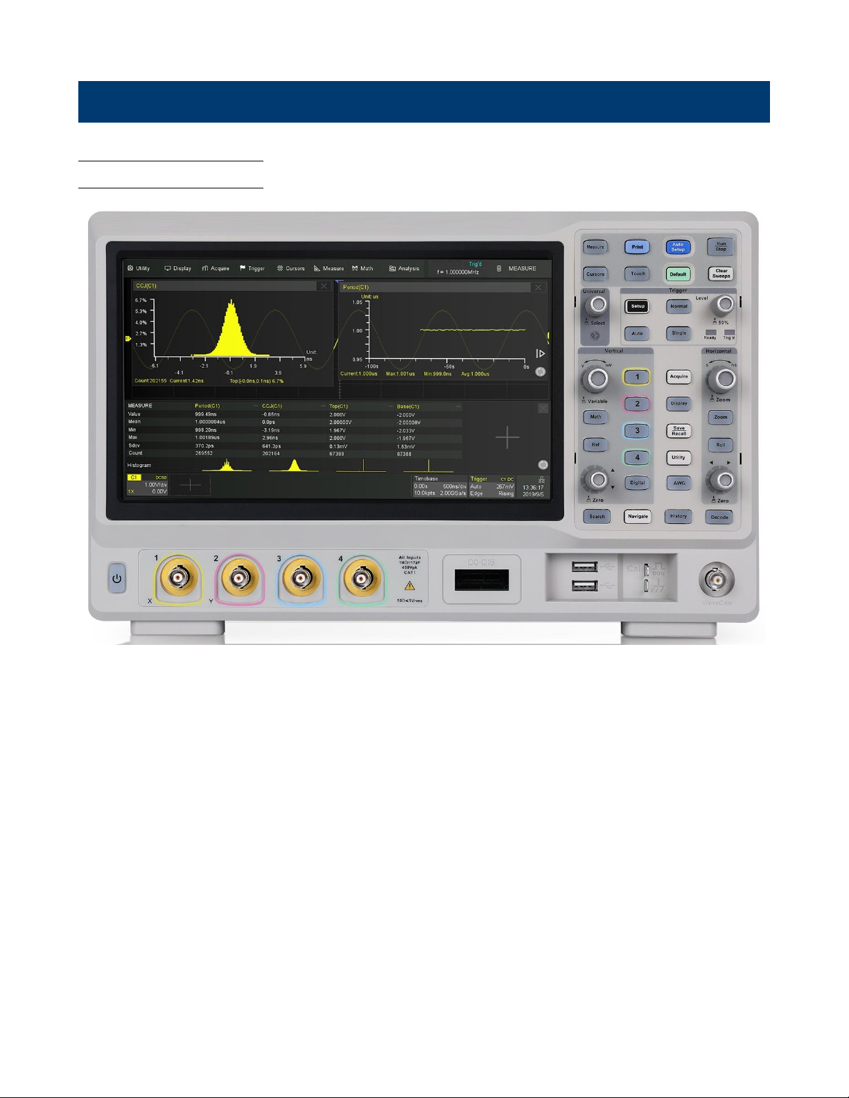
1.5 Front Panel Overview
The front panel interface allows for control of the unit.
Figure 1.3 Front Panel
Item
Name
Description
Visual presentation of the device function and measurements.
See section Touch Screen Display for more details.
2
Control Panel
Includes control knobs and keys. See section
Control Panel
3
WaveGen
Built-in waveform generator output.
4
Probe Compensation Supplies a 0-3.3 V, 1 kHz square wave for compensating the probes.
5
USB Host Port
USB port used to connect flash drives. (Type A)
6
Digital Input Connector Receives digital signals from the LP2560 digital probe.
7
Analog Input Channels Input channels (Default: 1 MΩ)
8
Power Button Power the unit ON or OFF.
Table 1.2 Front Panel
1
Touch Screen
Find Quality Products Online at: sales@GlobalTestSupply.com
www.GlobalTestSupply.com
Page 17

General Information
17
ger types.
1.6 Rear Panel Overview
Figure 1.4
Rear Panel Overview
Item
Name
Description
Outputs the trigger indicator. When Pass / Fail is enabled, outputs the
pass / fail signal.
2
External Trigger Input
The external trigger input can be used as a source in several of the trig-
3
USB Interface
Connect a USB type B to type A to remotely control the unit.
4
LAN
Connect an ethernet cable to remotely control the unit over the network.
lock the instrument to a fixed location using the security lock via the lock
hole. Lock is not included.
AC Power Input
& Fuse Box
Houses the fuse as well as the AC input .
7 Handle
Handle for easy carrying of the instrument.
Table 1.3 Rear Panel
1 Auxiliary Out
5
Safety Lock Hole
6
Find Quality Products Online at: sales@GlobalTestSupply.com
www.GlobalTestSupply.com
Page 18
General Information
18
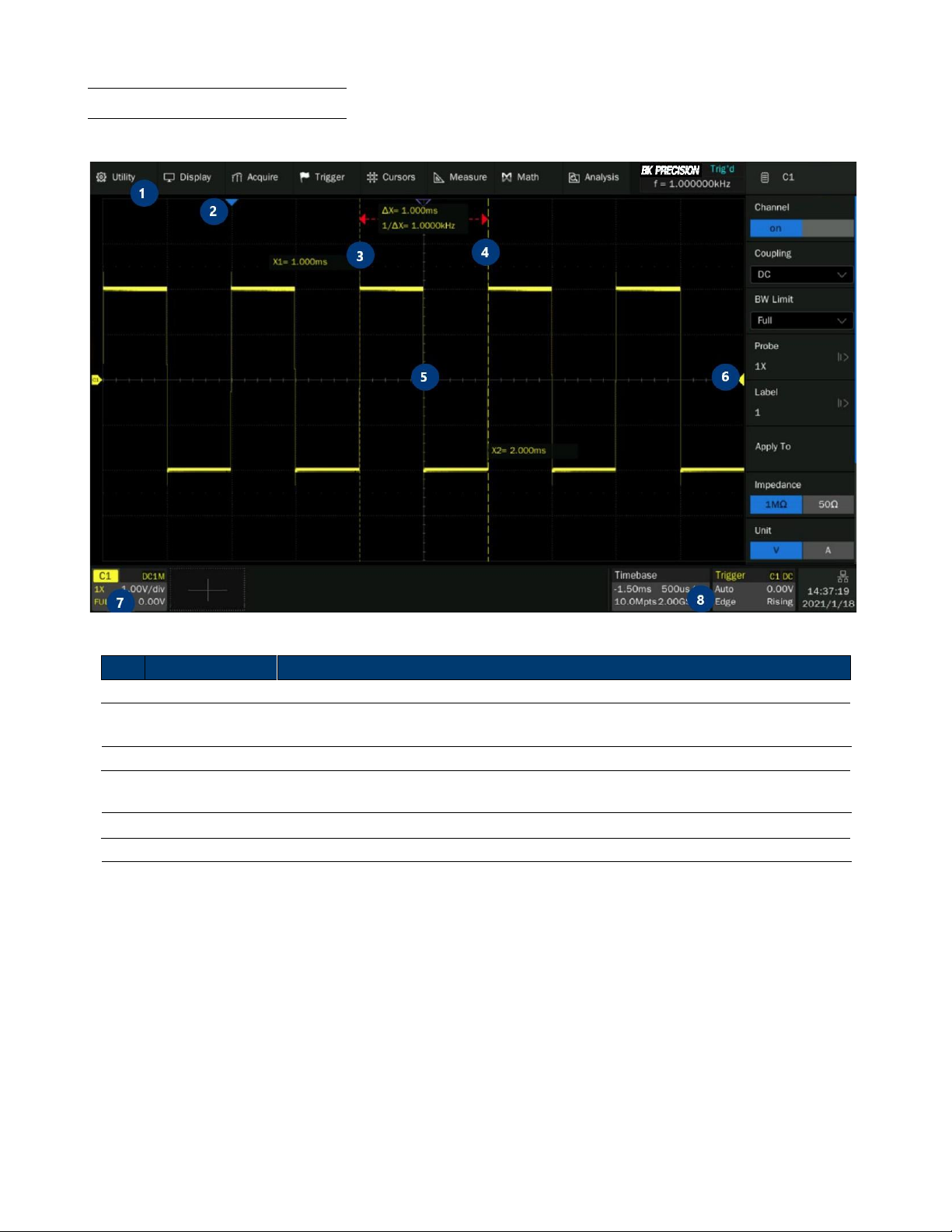
1.7 Touch Screen Overview
Use your fingers to touch, drag, pinch, spread, or draw a selection box.
Figure 1.5
Touch Screen Overview
Item Name
Description
1 Menu Bar
Displays the available options in the selected menu.
Trigger Delay
Indicator
Displays the trigger status.
3 Trigger Status
Displays the trigger status.
USB Host
Port Indicator
Indicates that a USB is connected to the instrument.
5
LAN Port Indicator Indicates the status of the LAN connection.
6
Menu Bar
Displays the available options in the selected menu.
Table 1.4
Touch Screen Overview
2 4
Find Quality Products Online at: sales@GlobalTestSupply.com
www.GlobalTestSupply.com
Page 19

SHOCK HAZARD:
Getting Started
Before connecting and powering up the instrument, review the instructions in this section.
2.1 Input Power Requirements
The oscilloscope has a universal AC input that accepts line voltage and frequency input within:
Line
Voltage Range
100-120 V
100-240 V
Frequency
400 Hz
50/60 Hz
Power
80W Max
Table 2.1
Before connecting to an AC outlet or external power source, be sure that the power switch is in the OFF position and
verify that the AC power cord, including the extension line, is compatible with the rated voltage/current and that there
is sufficient circuit capacity for the power supply. Once verified, connect the cable firmly.
The included AC power cord is safety certified for this instrument operating in rated range. To
change a cable or add an extension cable, be sure that it can meet the required power
ratings for this instrument. Any misuse with wrong or unsafe cables will void the warranty.
The power cord provides a chassis ground through a third conductor. Verify that your power
outlet is of the three-conductor type with the correct pin connected to earth ground.
Find Quality Products Online at: sales@GlobalTestSupply.com
www.GlobalTestSupply.com
Page 20

Getting Started
20
2.2 Fuse Requirements and Replacement
For continued fire protection at all line voltages replace only with a 2.00 A / 250 V "T" RATED, 5 x 20 mm
fuse.
For safety, no power should be applied to the instrument while changing line voltage
operation. Disconnect all cables connected to the instrument before proceeding.
Check and/or Change Fuse
–
Locate the fuse box next to the AC input connector in the rear panel. (See figure
1.4)
–
Insert a small flathead screwdriver into the fuse box slit to pull and slide out the fuse box as indicated below.
–
Check and replace fuse if necessary. (See figure
2.1)
Figure 2.1
Fuse Removal
Any disassembling of the case or changing the fuse not performed by an
authorized service technician will void the warranty of the instrument
Find Quality Products Online at: sales@GlobalTestSupply.com
www.GlobalTestSupply.com
Page 21

Getting Started
21
2.3 Preliminary Check
Complete the following steps to verify that the oscilloscope is ready for use.
2.3.1 Verify AC Input Voltage
Verify proper AC voltages are available to power the instrument.
The AC voltage range must meet the acceptable specification stated in section
Input Power Requirements.
2.3.2 Connect Power
Connect the AC power cord to the AC receptacle in the rear panel and press the power switch to turn on the instrument.
The instrument will have a boot up screen while loading, after which the main screen will be displayed.
2.3.3 Self-Test
The instrument has 3 self-test option to test the screen ,keyboard, and the LED back light.
To perform the self-test, please refer to the
Self Test
section for further instructions.
2.3.4 Self-Cal
Self option runs an internal self-calibration procedure that will check and adjust the instrument. To perform the selfcalibration, refer to the Self-Calibration section for further instructions.
2.3.5 Check Model and Firmware Version
The model and firmware version can be verified from within
the menu system.
To view the model and firmware version:
Press the
Utility
button and use the softkeys to select the
System Status
option. The following information will be
displayed:
–
Software Version
–
Uboot-OS Version
–
FPGA Version
–
CPLD Version
–
Hardware Version
–
Scope ID
–
Serial NO.
–
Model
Figure 2.2
System Status
Find Quality Products Online at: sales@GlobalTestSupply.com
www.GlobalTestSupply.com
Page 22

Getting Started
22
2.3.6 Function Check
Follow the steps below to do a quick check of the oscilloscope’s functionality.
1.
Power on the oscilloscope. Press "Default Setup" to show the result of the self-check.
–
The probe default attenuation is 1X.
2.
Set the switch to 1X on the probe and connect the probe to channel 1.
–
To do this align the slot in the probe connector with the key on the CH1 BNC, push to connect, and twist to the
right to lock the probe in place.
–
Connect the probe tip and reference lead to the Probe Comp connectors.
3.
Press the
AUTO
button to show the 1 kHz frequency and about 3V peak to peak square wave.
Figure 2.3
3 Vpp Square Wave
4.
Repeat steps 1 to 3 for the remaining channels.
Find Quality Products Online at: sales@GlobalTestSupply.com
www.GlobalTestSupply.com
Page 23

Getting Started
23
Shock Hazard:
2.4 Probe Safety
A guard around the probe body provides a finger barrier for protection from electric shock.
Figure 2.4 Probe
Connect the probe to the oscilloscope and connect the ground terminal to the ground before you take any measurements.
To avoid electric shock when using the probe, keep fingers behind the guard on the probe body. To avoid electric shock
while using the probe, do not touch metallic portions of the probe head while it is connected to a voltage source.
Connect the probe to the oscilloscope and connect the ground terminal to ground before you take any measurements.
Find Quality Products Online at: sales@GlobalTestSupply.com
www.GlobalTestSupply.com
Page 24

Getting Started
24
Note:
Probe Attenuation
Probes are available with various attenuation factors which affect the vertical scale of the signal. The Probe Check
function verifies that the probe attenuation option matches the attenuation of the probe.
Press CH 1 once to open the channel menu. Select the probe option that matches the attenuation of the probe.
The default setting for the Probe option is 1 X.
Verify that the attenuation switch on the probe matches the Probe option in the oscilloscope. Switch settings are 1 X
and 10 X.
Probe Compensation
Before taking any measurements using a probe, verify the compensation of the probe and adjust it to match the channel
inputs.
To match your probe to the input channel:
1.
Set the channel’s probe attenuation to 10X.
–
Press the
CH #
key corresponding to the channel the probe is connected to.
–
Use the softkeys to navigate to page 1.
–
Use the softkeys to select
Probe.
–
Use the
Intensity Adjust
knob to select 10X.
2.
Attach the probe tip to the
Compensation Signal Output Terminal 3 V(Cal
) connector and the reference lead to
the Probe Ground terminal connector.
–
Press the
Auto Setup
key to display the square wave.
3.
Check the shape of the displayed waveform.
Undercompensated Correctly Compensated
Overcompensated
Figure 2.5
Probe Compensation
4.
If necessary, adjust your probe’s compensation trimmer pot.
Find Quality Products Online at: sales@GlobalTestSupply.com
www.GlobalTestSupply.com
Page 25

Control Panel
The control panel is designed to operate the basic functions
without having to open the software menu. Most of the front
panel controls duplicate functionality available through the
touch screen.
All the knobs on the front panel are multifunctional.
They can be pushed as well as rotated. Pushing a
knob quickly recalls a specific function, which is
indicated by the silkscreen near to the knob.
The
Control Panel
consist of 9 sections:
•
Vertical Control
•
Horizontal Control
•
Trigger Control
•
Run/Stop Key
•
Auto Setup Key
•
Analysis Keys
•
Universal Knob
•
Menu Keys
•
Other Keys
Figure 3.1 Control Panel
3.1 Vertical Control
Channel Keys
: Press the channel keys to toggle a channel
On
or
Off
, or to access the
channel’s menu. There is one channel on/off key for each analog channel.
Digital Key
: Enable/disable the digitals channels and display the waveforms.
See section Digital Channels for more details.
Math Key
: The
Math
key provides access to the math (add, subtract, etc.) waveform
func
tions.
See section
Math
for more details.
Ref Key
: Toggle the reference function on and off.
Vertical Scale Knob
: Analog channels (C1-C4), digital channels (d), math (F1-F2) and
references (Ref) share the same vertical scale knob. Turn the knob to adjust the gain
(volts/div). Push to alternate between coarse and fine adjustments. When the digital
channel is active, rotate the knob to change the selected digital channel.
Vertical Position Knob
: Analog channels (C1-C4), digital channels (D), math (F1-F2)
and references (Ref) share the same vertical position knob. Turn the knob to adjust the
DC offset or vertical position of the channel. Push to set the position to zero.
Figure 3.2
Vertical Control
Find Quality Products Online at: sales@GlobalTestSupply.com
www.GlobalTestSupply.com
Page 26

Control Panel
26
3.2 Horizontal Control
Figure 3.3
Horizontal
Control
Horizontal Scale Knob
: Turn the knob to adjust the horizontal scale (time/div). The symbols
above the knob indicate that this control has the effect of spreading out or zooming in on the
waveform using the horizontal scale.
Push the horizontal scale knob to toggle between fine and coarse adjustment.
Zoom Key
: Press the
Zoom
key to split the oscilloscope display into Normal and Zoom sections.
See section Zoom for more details.
Roll Key
: Toggle the roll function on and off. At timebase settings larger than 50 ms/div, it is
recommended to set the oscilloscope to Roll mode so that the waveform is displayed in real time.
See section Roll Mode for more details.
Horizontal Position Knob
: Turn the knob marked to pan through the waveform data
horizontally. The captured waveform before the trigger (turn the knob clockwise) or after the
trigger (turn the knob counterclockwise) can be seen. Panning through the waveform when the
oscilloscope is stopped (not in Run mode) will display the waveform data from the last acquisition
taken.
Push the horizontal position knob to zero the horizontal position.
3.3 Trigger Control
Figure 3.4 Trigger Control
The Trigger controls determine how the oscilloscope triggers to capture data. These controls consist of:
Setup
: Opens the
Trigger Setup
menu. In the
Trigger Setup
menu, the trigger type, source, and options that
affect
all trigger types can be set. See section Triggers for more details.
Normal
: Sets the
Trigger Mode
to
Normal
. In
Normal Mode
acquisitions only occur when the trigger conditions are
met. Otherwise, the oscilloscope holds the last waveform on the display and waits for the next trigger.
Auto
: Sets the
Trigger Mode
to
Auto
. In
Auto Mode
an internal timer triggers the sweep after a preset timeout
period if no trigger has been found so that the oscilloscope continuously updates the display whether a trigger occurs or
not.
Find Quality Products Online at: sales@GlobalTestSupply.com
www.GlobalTestSupply.com
Page 27
Control Panel
27
Single
: Sets the
Trigger Mode
to
Single
. In
Single Mode
data is a single frame that satisfies the trigger conditions is
captured and displayed, and then stops. The following trigger events are ignored until
Single
acquisition is restarted.
Level Knob
: Turn the
Level Knob
to adjust the trigger level for a selected analog channel. Push the knob to set the
level to the waveform’s 50% value. If AC coupling is used, pushing the
Level Knob
sets the trigger level to about 0 V.
Trigger Status
: Indicates when the oscilloscope is waiting for a trigger or when a trigger has occurred.
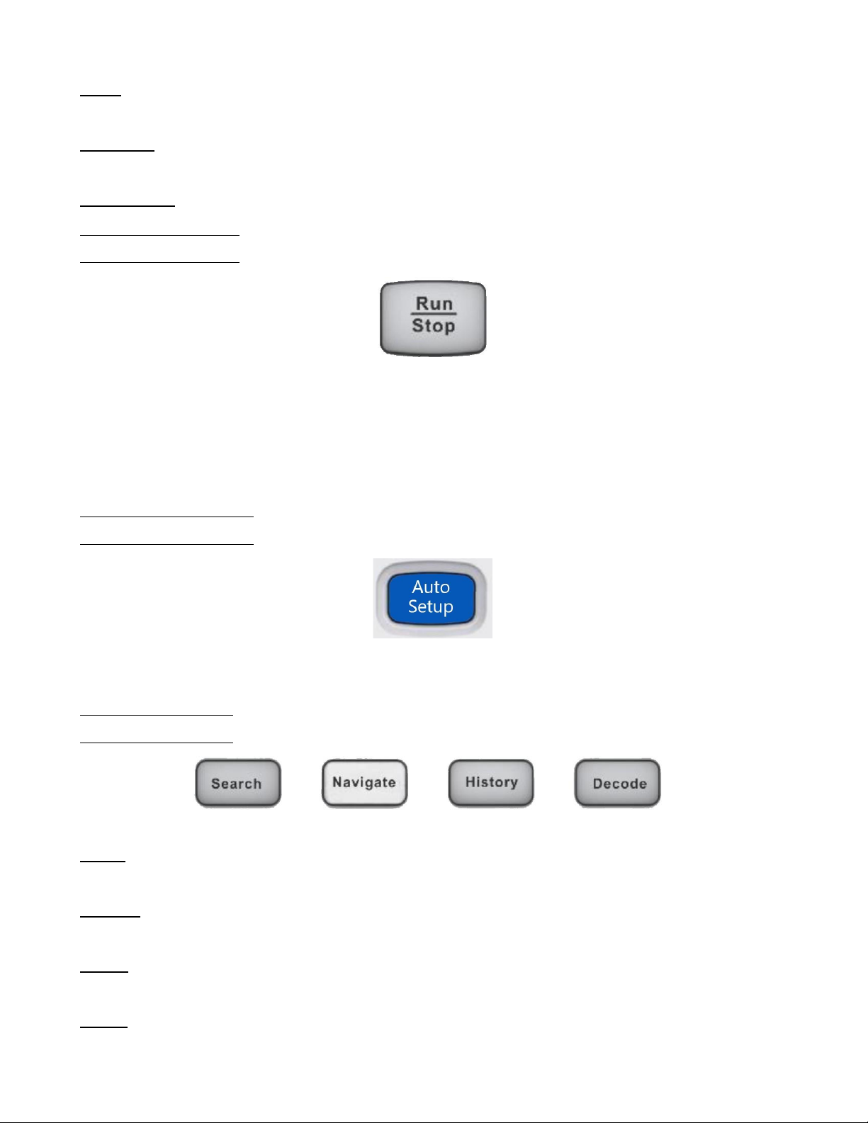
3.4 Run/Stop Key
When the
Run/Stop
key is green, the oscilloscope is running, that is, acquiring data when trigger conditions are met.
To stop acquiring data, press the Run/Stop key.
When the
Run/Stop
key is red, data acquisition is stopped. To start acquiring data, press the
Run/Stop
key.
To capture and display a single acquisition (whether the oscilloscope is running or stopped), press the
Single
key. The
Single
key will remain green until the oscilloscope triggers.
3.5 Auto Setup Key
Pressing the
Auto Setup
key will cause the oscilloscope to determine which channels have activity, and it will turn these
channels on and scale them to automatically configure the input to best display the input signals.
3.6 Analysis Keys
Figure 3.5
Common Functions
Search
: Search for events in the acquired data.
See section Search for more details.
Navigate
: Navigate through captured data via time, search events, or history frame.
See section Navigate for more details.
History
: Divides the oscilloscope’s memory into segments allowing for analysis of individual frames.
See section History for more details.
Decode
: Enable serial decode.
See section Serial Decode for more details.
Find Quality Products Online at: sales@GlobalTestSupply.com
www.GlobalTestSupply.com
Page 28

Control Panel
28
3.7 Universal Knob
Figure 3.6
Universal Knob
3.8 Menu Keys
The
Universal Knob
is used to select items from pop-up menus and to change values. The
function of the
Universal Knob
changes based upon the current menu.
Note that the curved arrow symbol below the knob illuminates whenever the
Universal
Knob
can be used to select a value. Also, note that when the
Universal Knob symbol ap-
pears, you can use the Universal Knob, to select values.
Rotating the
Universal Knob
adjusts the trace intensity. Pushing
the Universal Knob
instantly sets the intensity to 50%.
Acquire
: Access the
Acquire
menu. In the acquire menu Interpolation,
Acquire Mode, Acquisition, Memory Depth, Sequence, and Resolution can be set.
See section Acquire for more details.
Display
: Access the
Display
menu to enable persistence, adjust the display grid (graticule)
intensity, label waveforms, add an annotation, and clear the display.
See section Display for more details.
Save/Recall
: Save oscilloscope setups, screen images, waveform data, or mask files or to
recall setups, mask files or reference waveforms.
See section
Save/Recall
for more details.
Utility
: Access the
Utility
menu, to configure the oscilloscope’s I/O settings, use the file
explorer, set preferences, access the service menu, and choose other options.
AWG
: Built-in waveform generator can output arbitrary, sine, square, ramp, pulse,
DC, noise, and other 45 built-in waveforms. Modulated waveforms are available
except for arbitrary, pulse, DC, and noise waveforms.
See section
Arbitrary Waveform Generator
for more details.
Figure 3.7
Menu Keys
Find Quality Products Online at: sales@GlobalTestSupply.com
www.GlobalTestSupply.com
Page 29

Control Panel
29
3.9 Other Keys
Press the
Measure
key to access a set of predefined measurements.
See section Measure for more details.
Performs a screenshot save to an external storage device.
The supported format includes .bmp .jpg .png
Enables/Disables the touch screen.
The LED on the button lights to indicate that the touch screen is working.
Enables/disable the cursors. Cursors are used to make custom measurements.
See section Cursors for more details.
Restores the oscilloscope’s default settings.
Clears the displayed data and any measurements, including display persistence, measurement statistics,
average sweeps, and Pass/Fail statistics.
Find Quality Products Online at: sales@GlobalTestSupply.com
www.GlobalTestSupply.com
Page 30
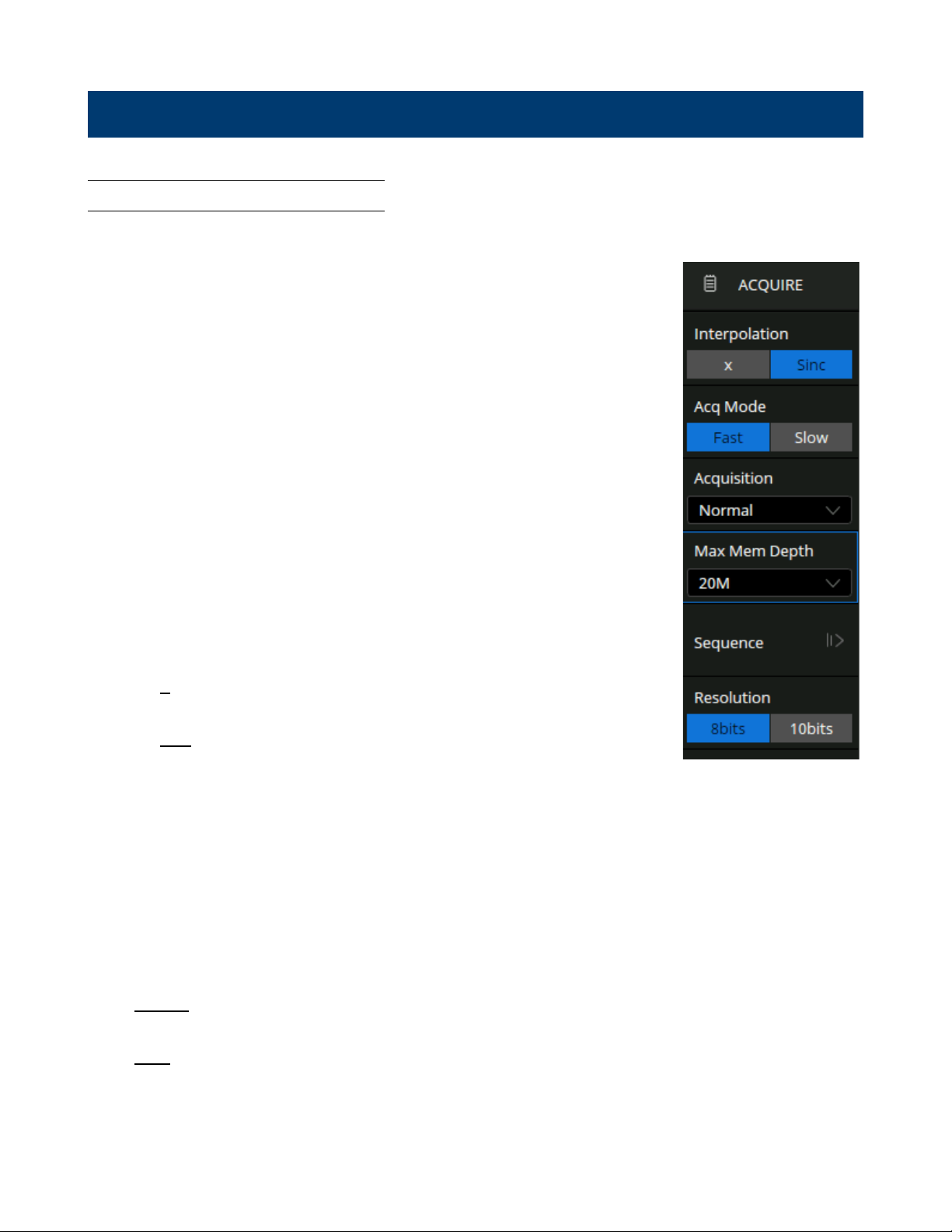
Acquisition
4.1 Changing Acquisition Mode
To change the Acquisition Mode:
•
Use the touchscreen to press the
Acquire Menu
on the
Main Timebase
menu, or press the
Acquire
key on the control panel, or touch the Menu Bar
and select
Acquire > Menu
to recall the Acquire menu on the right side.
–
the
Acquire
menu shown in figure
4.1
will be displayed.
•
Touch
Resolution
to toggle between
8bits
and
10bits
resolution.
–
The vertical resolution. "8-bits" is the default setting.
–
In
10-bits
mode, the vertical resolution is 4x better, while the bandwidth
is limited to about 100 MHz.
•
Touch
Interpolation
to toggle between x and
Sinc.
•
At small timebase settings, the number of original points on the screen
may be less than the number display pixels in the grid area, so
interpolation is necessary to display a continuous waveform. For
example, at 1 ns/div timebase and 2 GSa/s sample rate, the number of
original points is 20, but the grid area includes 1000 horizontal pixels. In
this case, the
oscilloscope needs to interpolate the original points by
50.
–
X
: Linear interpolation, the simplest way of interpolation, connects
two original points with a straight line.
–
Sinc
: Sin(x)/x interpolation, the original point is interpolated
according to the Nyquist reconstruction formula, which has a good
time- domain recovery effect for sine wave. But for step signals/fast
rise
times, it will introduce false overshoot due to the Gibbs phenomenon.
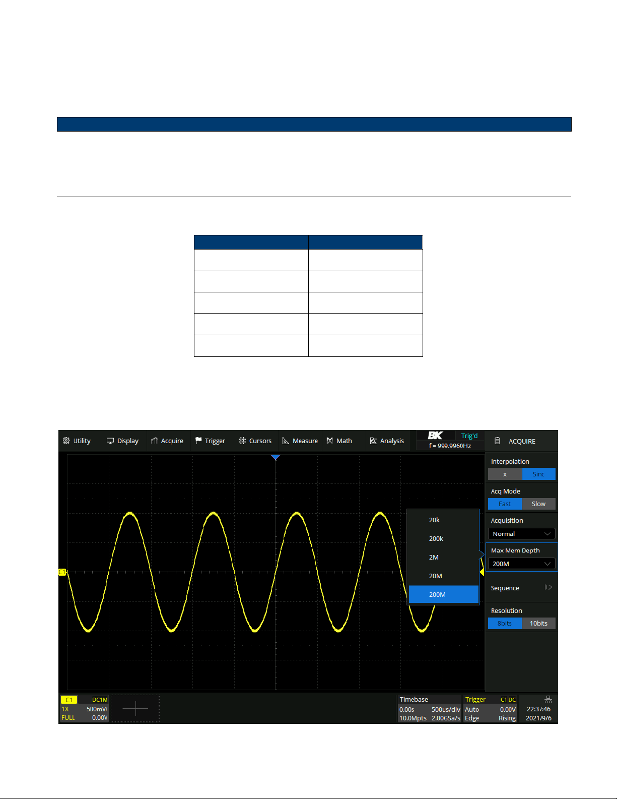
Figure 4.1 Acquire Menu
•
Touch
Acq Mode
to toggle between
Fast
and
Slow
acquisition.
–
Fast
is the default setting. A very high waveform update rate is provided in fast mode.
–
Slow
mode will slow down the waveform update.
•
Touch
Acquisition
to determine how to acquire and process the signal.
•
Normal
: The oscilloscope samples the signal with an equal time interval. For most waveforms, the best display
effect can be obtained using this mode.
•
Peak
: The oscilloscope acquires the maximum and minimum values of the signal within the sample interval so
that the peak (maximum – minimum) in the interval is obtained. This mode is effective to observe occasional
narrow pulses or spurs with a low sample rate, but the noise displayed is larger. In peak mode, the oscilloscope
will display all pulses with a pulse width longer than 400 ps.
•
Touch
Memory Depth
to set the maximum memory depth that is supported.
Find Quality Products Online at: sales@GlobalTestSupply.com
www.GlobalTestSupply.com
Page 31
Acquisition
31
Note:
–
acquisition time = sample points x sample interval", setting a larger memory depth can achieve a higher sample
rate for a given time base, but more samples require more processing time, degrading the waveform update rate.
With 200 Mpts memory depth, the 2560B series can still run at full sample rate (2 GSa/s) even when set to the
10 ms/div timebase.
The memory depth here is the upper limit of the memory space allocated by the oscilloscope. The actual sample
points are related to the current timebase and may be less than memory depth. The actual sample points
information can be obtained in the timebase descriptor box (see the section "Timebase and Trigger" for details).
The maximum memory depth in single-channel mode is 2 times that of the dual-channel mode, as the following table:
Single-Channel Mode
Dual-Channel Mode
20k
10k
200k
100k 2M 1M
20M
10M
200M
100M
Table 4.1 Memory Depth
Single-channel mode (interleaving mode): Only one of C1/C2 is turned on, and only one of C3/C4 is turned on.
Dual-channel mode (non-interleaving mode): Both C1/C2 are turned on, or both C3/C4 are turned on.
Figure 4.2 Memory Depth
Find Quality Products Online at: sales@GlobalTestSupply.com
www.GlobalTestSupply.com
Page 32

Acquisition
32
4.2 Sequence
Sequence mode is a fast acquisition mode, which divides the memory depth to multiple segments (up to 90,000), each
of which stores a single shot.
In sequence mode, the oscilloscope only acquires and stores data without processing and displaying, until the specified
segments are acquired. As a result, the dead time between trigger events is minimized, improving the waveform update
rate.
If sequence mode is enabled, the display will not update until all of the sequences have been acquired. The 2560B series
can achieve a minimum 2 s trigger interval in sequence mode, corresponding to a waveform update rate of 500,000
wfms/s.
Sequence mode can capture and record rare events over long time periods. The oscilloscope can capture multiple events
that satisfy the trigger conditions, ignoring the periods of no interest between adjacent events, maximizing the use of
waveform memory. Full accuracy of the acquisition timebase can be used to measure selected segments.
After the acquisition is finished, the oscilloscope will map all the segments together to the screen. To view and analyze
each frame separately, use history mode (see the section " History" for details). History mode provides timestamp labels
for each segment.
Figure 4.3
Sequence
Find Quality Products Online at: sales@GlobalTestSupply.com
www.GlobalTestSupply.com
Page 33

History
The history function can record the waveforms of the input channels before press the
Run/Stop
button. In run state,
the oscilloscope records input waveform continually; when the memory is full (reach the maximal frame), the new frames
will cover the old frames and keep the latest frames.
The oscilloscope automatically stores acquired frames. It can store up to 90,000 frames but the number may vary due to
the memory depth and timebase settings. Turn on history mode, then the stored frames can be recalled and measured.
In sequence mode, all waveforms that satisfy the trigger conditions are mapped to the display.
To view a single frame:
1.
Press the
History
button on the front panel to enable the History function.
–
The history menu shown in figure
5.1
will be displayed.
2.
Touch
History
to toggle the history function on and off.
3.
Touch
Frame No.
and use the
Universal Knob
or the virtual keypad to
specify the frame index.
4.
Touch
List
to toggle the list function on and off.
5.
Touch the navigation options on to play backward, stop, or play
forward.
–
Touch
List Time Type
to toggle the type between
Acq Time
and
Delta T.
6.
Touch
Interval Time
to set the playing interval by using the
Universal
Knob or the virtual keypad.
•
In addition to manually specifying a frame, history mode supports autoplay.
–
Touch the option to replay the waveform from the current frame
to the first.
–
Touch the option to stop replay.
–
Touch the option to replay the waveform from the current frame
to the last.
Figure 5.1 History Menu
Find Quality Products Online at: sales@GlobalTestSupply.com
www.GlobalTestSupply.com
Page 34

Horizontal Control
The horizontal controls include:
•
Touchscreen controls for setting :
–
Horizontal scale and position (delay)
–
Accessing the
Main Timebase
menu.
–
Navigating
•
The horizontal scale and position knobs.
•
The
Zoom
key for quickly enabling/disabling the split-screen zoom display.
•
The
Search
key for finding events on analog channels or in serial decode.
•
The
Navigate
keys for navigating time, search events, or segmented memory acquisitions.
6.1 Adjusting the Horizontal Scale (time/div)
To adjust the horizontal scale:
•
Use the touchscreen horizontal pinch gesture
•
Use the touchscreen controls to open the
Main Timebase
dialog by pressing the timebase descriptor box.
Figure 6.1
Timebase Descriptor Box
–
Press the
Timebase
box to set the horizontal scale by the
virtual keypad.
– Press
to increase and to decrease the horizontal
scale.
•
The
Horizontal Scale Knob
can also be turned to adjust the
horizontal time/div setting.
Figure 6.2
Main Timebase Menu
The
Horizontal Scale Knob
has a different purpose in the
Zoom display.
See section
Zoom
for more details
Note:
Find Quality Products Online at: sales@GlobalTestSupply.com
www.GlobalTestSupply.com
Page 35

Horizontal Control
35
6.2 Adjusting the Horizontal Delay (position)
Figure 6.3 Horizontal Setup
To adjust the horizontal delay (position):
•
Use the touchscreen horizontal drag gesture.
•
Use the touchscreen controls to open the
Main Timebase
dialog by pressing the timebase descriptor box.
Figure 6.4
Timebase Descriptor Box
–
Press the
Delay
box to set the horizontal scale by the
vir
tual keypad. (Figure 6.5)
– Press
to increase and to decrease the horizontal
scale.
•
The
Horizontal Position Knob
can also be turned to adjust
the horizontal time/div setting.
Figure 6.5 Main Timebase Menu
Find Quality Products Online at: sales@GlobalTestSupply.com
www.GlobalTestSupply.com
Page 36

Horizontal Control
36
Note:
Changing the delay time moves the trigger point (solid inverted triangle
) horizontally and indicates how far it is
from the time reference point (hollow inverted triangle ). These reference points are indicated along the top of the
display grid.
Figure
6.3
shows the trigger point with the delay time set to 170 µs. The delay time number tells you how far the time
reference point is located from the trigger point. When delay time is set to zero, the delay time indicator overlays the
time reference indicator.
All events displayed left of the trigger point happened before the trigger occurred. These events are called pre-trigger
information, and they show events that led up to the trigger point.
Everything to the right of the trigger point is called post-trigger information. The amount of delay range (pre-trigger
and post-trigger information) available depends on the time/div selected and memory depth.
The horizontal position knob works (in the Normal time mode) while acquisitions are running or when they are stopped.
When running, adjusting the horizontal scale knob changes the sample rate. When stopped, adjusting the horizontal
scale knob lets you zoom into acquired data.
The
Horizontal Position Knob
has a different purpose in the
Zoom display.
See section
Zoom
for more details
6.3 Panning and Zooming Single or Stopped Acquisitions
When the oscilloscope is stopped, use the touchscreen horizontal pinch or drag gestures or use the horizontal scale
and position knobs to pan and zoom your waveform. The stopped display may contain several acquisitions worth of
information, but only the last acquisition is available for pan and zoom.
The ability to pan (move horizontally) and scale (expand or compress horizontally) an acquired waveform is important
because of the additional insight it can reveal about the captured waveform. This additional insight is often gained from
seeing the waveform at different levels of abstraction. You may want to view both the big picture and the specific little
picture details. For example, figure
6.3
demonstrates how these features bring insight on the waveform’s rise time.
6.4 Horizontal Scale (Coarse/Fine)
To change the horizontal scale knob adjustment setting:
•
Push the
Horizontal Scale Knob
to toggle between fine and coarse adjustment.
When Fine is enabled, turning the horizontal scale knob changes the time/div (displayed in the status line at the top of
the display) in smaller increments. The time/div remains fully calibrated when Fine is on.
When Fine is turned off, the Horizontal scale knob changes the time/div setting in a 1-2-5 step sequence.
Find Quality Products Online at: sales@GlobalTestSupply.com
www.GlobalTestSupply.com
Page 37

Horizontal Control
37
6.5 Zoom
Zoom is a horizontally expanded version of the normal display. When Zoom is selected, the display divides into two
windows. The top window covers about a third of the displays. This window displays the normal time/div window. The
area of the normal display that is expanded is outlined with a box and the rest of the normal display is ghosted. The box
shows the portion of the normal sweep that is expanded in the lower half.
The bottom window covers two-thirds of the screen. This window is a magnified portion of the normal time/div window.
Use Zoom to locate and horizontally expand part of the normal window for a more detailed analysis of the waveform.
To enable the Zoom function:
•
Press the
Zoom
key or push the
Horizontal Scale Knob.
–
Zoom can also be enabled using the touch screen. Press the Acquire option located on the Menu Bar. Then
press Zoom.
Figure 6.6 Zoom
To change the time/div for the Zoom window, turn the
Horizontal Scale Knob
. As you turn the knob, the zoomed
window time/div is highlighted in the status line above the waveform display area. The Horizontal scale knob controls
the size of the box.
The Horizontal position knob sets the left-to-right position of the zoom window. Negative delay values indicate you’re
looking at a portion of the waveform before the trigger event, and positive values indicate you’re looking at the waveform
after the trigger event.
To change the time/div of the normal window, turn off Zoom by pressing the
Zoom
key ; then, turn the
Horizontal Scale
Knob.
Find Quality Products Online at: sales@GlobalTestSupply.com
www.GlobalTestSupply.com
Page 38

Horizontal Control
38
6.6 Roll
Roll causes the waveform to move slowly across the screen from right to left. It only operates on the time bases settings
of 50 ms/div and slower. If the current time base settings are faster than the 50 ms/div limit, it will be set to 50 ms/div
when Roll mode is entered.
To enable the Roll mode:
•
Press the
Roll
key.
–
Roll can also be enabled using the touch screen. Press the
Acquire
option located on the Menu Bar.
Then press
Roll.
In Roll mode there is no trigger. The fixed reference point on the screen is the right edge of the screen and refers to
the current moment in time. Events that have occurred are scrolled to the left of the reference point. Since there is no
trigger, no pre-trigger information is available.
If you would like to pause the display in Roll mode press the
Single
key. To clear the display and restart an acquisition
in Roll mode, press the [Single] key again.
Use Roll mode on low-frequency waveforms to yield a display much like a strip chart recorder. It allows the waveform to
roll across the display.
Find Quality Products Online at: sales@GlobalTestSupply.com
www.GlobalTestSupply.com
Page 39

Vertical Control
The vertical controls include:
•
Touchscreen controls for setting:
–
Vertical scale and position (offset)
– Accessing the
Channel
menus.
•
The vertical scale and position knobs for each analog channel.
•
The channel keys for turning a channel on or off.
Figures
7.2
shows the Channel 1 Menu that appears after pressing the 1 channel key.
7.1 Enabling Channels
Push the channel button (1 - 4) to turn on the corresponding channel. Its channel
descriptor box and Channel menu will appear on the display. Push the same button
again
to disable the channel. The channel menu also has an on/off option.
7.1.1 Channel Enable/Disable From the Touch Screen
Touch the + button shown on figure
7.1
and then select a channel to turn it on. The
selected channel’s descriptor box and a menu box will appear on the display. Touch the
channel descriptor box and then touch the Off button to disable it.
Figure 7.2 Channel 1 Menu
Turn CH 1 On Turn CH 1 Off
Figure 7.1 Front View
Figure 7.3
Channel 1 Menu
Continued
Find Quality Products Online at: sales@GlobalTestSupply.com
www.GlobalTestSupply.com
Page 40

Vertical Control
40
7.2 Vertical Scale
The
Vertical Scale Knob
changes the analog channel scale in a 1-2-5
step sequence (with a 1:1 probe attached), unless Fine Adjustment is enabled.
The analog channel’s vertical scale (Volts/div) value is displayed in the
channel’s
descriptor box.
To adjust the vertical scale:
•
Use the touchscreen vertical pinch gesture.
•
Touch the channel descriptor box to open the vertical scale/offset dialog.
•
Turn the
Vertical Scale Knob.
7.2.1 Coarse/Fine Adjustment
Push the channel’s vertical scale knob (or press the channel’s descriptor box then
uncheck Coarse) to toggle between fine and coarse adjustment of the vertical scale.
When
Fine
adjustment is selected, you can change the channel’s vertical sensitivity in
smaller increments. The channel sensitivity remains fully calibrated when
Fine
is on.
When Fine is turned off, turning the
Vertical Scale Knob
changes the channel
sensi
tivity in a 1-2-5 step sequence.
7.3 Vertical Position
The offset voltage value represents the voltage difference between the vertical center
of the display and the ground level (
) icon.
To adjust the vertical position:
•
Use the touchscreen pinch and drag gestures.
•
Touch the channel descriptor box to open the vertical scale/offset dialog.
•
Turn the
Vertical Position Knob
to move the channel’s waveform up or down on
the display.
Figure 7.4
Channel Descriptor Box
Figure 7.5
Vertical Scale/Offset
Dialog
Push the
Vertical Position Knob
to set the ground level to zero.
Note:
Find Quality Products Online at: sales@GlobalTestSupply.com
www.GlobalTestSupply.com
Page 41

Vertical Control
41
Note:
Note:
7.4 Channel Setup
Pressing the
Channel
key to open the corresponding channel menu. As shown in figures
7.2
and
7.3
the following
options can be configured:
•
Channel Coupling
•
BW Limit
•
Probe
•
Label
•
Apply To
•
Impedance
•
Unit
•
Deskew
•
Invert
•
Trace
7.4.1 Channel Coupling
Coupling changes, the channel’s input coupling to either
AC
(alternating current),
DC
(direct current), or
GND
(ground).
DC (Direct Current)
All of the input signal frequency components are passed to the display.
DC coupling is useful for viewing waveforms as low as 0 Hz that do not have large DC offsets.
If the channel is DC coupled, you can quickly measure the DC
component of the signal by simply noting its distance from the ground.
Alternating Current
The signal is capacitively coupled. DC signal components are rejected. See the datasheet for details of the cut-off
frequency.AC coupling is suitable for observing AC signals with DC offset, such as power ripple.
AC coupling is useful for viewing waveforms with large DC offsets.
AC coupling places a 10 Hz high-pass filter in series with the input waveform that removes any DC offset voltage from
the waveform.
If the channel is AC coupled, the DC component of the signal is removed,
allowing for greater sensitivity to display the AC component of the signal.
Ground
The channel is grounded by an internal switch. GND coupling is used to observe the zero offset error of the analog
channels or determine the source of noise in the waveform (from signal or from oscilloscope itself).
Find Quality Products Online at: sales@GlobalTestSupply.com
www.GlobalTestSupply.com
Page 42

Vertical Control
42
Note:
To set the channel coupling:
1.
Press the desired channel key.
2.
In the
Channel Menu
, use the touchscreen to press the
Coupling
option.
–
A drop-down menu will appear with all 3 coupling option.
–
Use the touchscreen to select the desired coupling.
Channel Coupling
is independent of
Trigger Coupling
. To change trigger coupling see
Trigger Coupling.
7.4.2 Bandwidth Limit
Full bandwidth will pass through signals with high-frequency components, but it also means that noise with high-frequency
components can pass through. When the frequency component of a signal is very low, better signal-to-noise ratios (SNR)
can be obtained by enabling one of the available bandwidth limits.
The 2560 provides two bandwidth limit options: 20 MHz and 200 MHz. The bandwidth limit effectively lowers the input
frequency response of the input to the selected limit value.
For waveforms with frequencies below the bandwidth limit, turning the bandwidth limit on removes unwanted high
frequency noise from the waveform.
To set the bandwidth limit:
1.
Press the desired channel key.
2.
In the
Channel Menu
, use the touchscreen to press the
BW Limit
option.
–
A drop-down menu will appear with three bandwidth options.
–
Use the touchscreen to select the desired bandwidth limit.
7.4.3 Probe Attenuation
This is set automatically if the oscilloscope can identify the connected probe. The 2560 provides 1X, 10X, 100X
and custom probe attenuation factor options. The custom values can be between 10−6 𝑡𝑜 106. The oscilloscope will
automatically convert the vertical scale according to the current probe attenuation factor.
For example, the vertical scale of the oscilloscope under 1X attenuation is 100 mV/div, and the vertical scale will be
automatically set to 1 V/div if the probe attenuation is changed to 10X. If a standard probe with readout terminal is
connected, the oscilloscope will automatically set the probe attenuation to match the probe.
To set the probe attenuation:
1.
Press the desired channel key.
2.
In the
Channel Menu
, use the touchscreen to press the
Probe
option.
–
The
Probe
submenu will appear with four bandwidth options.
–
Use the touchscreen to select the desired probe attenuation.
Find Quality Products Online at: sales@GlobalTestSupply.com
www.GlobalTestSupply.com
Page 43

Vertical Control
43
7.4.4 Label
Customize the label text, of the selected source. The source can be C1 - C4, F1 or F2, and RefA - RefD.
The length of the label is limited to 20 characters. The characters beyond this length will not be displayed.
When the
Display
option is set to “on”, the label will be displayed on the right side of the channel offset indicator.
To set and enable a channel’s label:
1.
Press the desired channel key.
2.
In the
Channel Menu
, use the touchscreen to press the
Label
option.
–
The
Label
submenu will appear.
•
Select a source to assign the label to the specified source.
•
Enable/disable the label using the
Display
option
•
Set the text of the label in the
Label Text
option.
Figure 7.6
Label Submenu
Label On Label Off
Figure 7.7
Label
7.4.5 Apply To
Common functions such as Trigger, Cursor, Measure, FFT, Search, Mask Test, Counter, and AWG can be quickly applied
to the selected channel using the
Apply To
option. Once a function is specified, it will switch directly to the function
menu and automatically set that channel as the source.
To apply a function:
1.
Press the desired channel key.
2.
In the
Channel Menu
, use the touchscreen to press the
Apply To
option.
–
A drop-down menu will appear listing the available functions.
–
Use the touchscreen to select the desired function.
Find Quality Products Online at: sales@GlobalTestSupply.com
www.GlobalTestSupply.com
Page 44

Vertical Control
44
7.4.6 Impedance
To change the impedance:
1.
Press the desired channel key.
2.
In the
Channel Menu
, use the touchscreen to select either
50 Ω or
1 MΩ.
1 MΩ: When a passive probe with high impedance is connected, the impedance must be set to 1 MΩ, otherwise the
signal will not be detected.
50 Ω: Suitable for high-frequency signals transmitted through 50 Ω coaxial cables and can minimize the amplitude
distortion caused by impedance mismatching.
7.4.7 Unit
Channel sensitivity, trigger level, measurement results, and math functions will reflect the measurement units selected.
To change the units:
1.
Press the desired channel key.
2.
In the
Channel Menu
, use the touchscreen to select either V or A.
Use Volts for a voltage probe.
Use
Amps
for a current probe.
7.4.8 Deskew
When measuring time intervals in the nanoseconds (ns) range, small differences in cable length can affect the
measure
ment. Use Deskew to remove cable-delay errors between any two channels.
For example, two coaxial cables with a 1-inch difference in length could introduce a skew of more than 100 ps. In some
scenarios (e.g. measuring the setup/hold time between clock and data), it may be necessary to compensate the skew
between channels.
The method of compensation: Probe the same signal simultaneously using two channels (including the cables or probes
that you intend to use for measurements) and adjust the deskew parameter of one channel until the waveforms of the
two channels observed on the screen coincide horizontally.
Find Quality Products Online at: sales@GlobalTestSupply.com
www.GlobalTestSupply.com
Page 45
Vertical Control
45
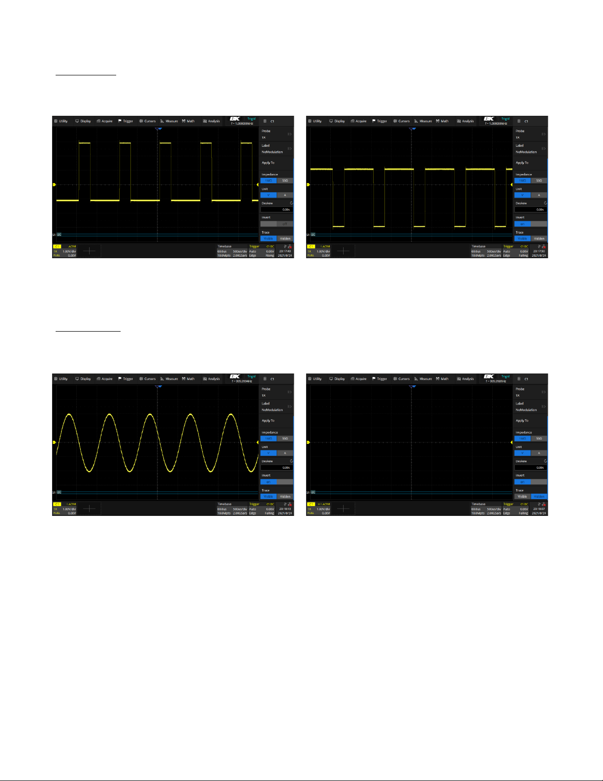
7.4.9 Invert
When
Invert
is enabled, the waveform is displayed 180 degrees opposite to the earth potential. This is a mathematical
inversion and does not physically change the actual potential of the input signal.
Invert Of
Invert On
Figure 7.8
Invert
7.4.10 Trace
When
Visible
is selected, the waveform is displayed.
When
Hidden
is selected, the waveform is not displayed, but the channel is still active.
Visible Hidden
Figure 7.9
Trace
Find Quality Products Online at: sales@GlobalTestSupply.com
www.GlobalTestSupply.com
Page 46

Note:
Digital Channels
This chapter describes how to use the digital channels of a Mixed-Signal Oscilloscope (MSO).
The digital channels are standard on the 2560B MSO models and the 2560B Series DSO models have the upgrade license
option.
8.1 LP2560 Probe
The LP2560 is a logic probe designed to monitor up to 16 digital signals at once. The 16 digital channels are separated
into two groups and each group has its threshold, making it possible to simultaneously view data from different logic
families.
The 16-channel color-coded logic probe consists of
two eight-channel pods. To make contact with the
DUT, the probe connects directly to square pins or
clips to test points using the included grabbers.
With an input capacitance of only 18 pF and 100 kΩ
input impedance, the probe protects the integrity of
your signal.
The probe is included with MSO models.
Figure 8.1 LP2560 Probe
To avoid personal injury or damage to the logic probe and any
associated equipment, the following safety precautions should be noted.
The equipment shall be used only for the purposes specified by the manufacturer.
The LP2560 probe is used only for BK’s special series of oscilloscopes. Protection mechanisms can be compromised if
the way the devices connected by the LP2560 are not used for their intended purpose.
Connect and disconnect correctly
.
Excessive bending can damage the cable.
Do not use equipment in humid or explosive environment.
Only used indoors. The LP2560 is designed to be used indoors and should only be operated in a clean, dry environment.
Do not use the equipment when you suspect a problem.
Do not use the LP2560 if any parts are damaged. Maintenance work shall be performed by maintenance personnel with
appropriate qualifications. Keep the product surface clean and dry.
Find Quality Products Online at: sales@GlobalTestSupply.com
www.GlobalTestSupply.com
Page 47

Digital Channels
47
8.2 Connecting the Digital Probes
1.
If necessary , turn off the power supply to the device under test.
–
Turning off power to the device under test only prevents damage that might occur if two lines are accidentally
shorted when connecting the probes. The oscilloscope can be powered on because no voltage appears at the
probes.
2.
Connect the digital probe cable to the
D0-D15
connector located on the front panel.
3.
Connect a SMD Mini-grabber test clip to one of the digital ground pins of the probe and then connect the grabber
to ground in the device under test.
–
This will improve the signal fidelity and makes sure the oscilloscope gives accurate measurements.
4.
Connect a flying lead probe to one of the digital channel pins; connect a grabber to the flying lead probe, and then
connect the grabber to the node in the circuit to be tested.
5.
Repeat step 4 until all points of interest are connected.
Figure 8.2 Connecting Digital Probes
8.3 Acquiring Digital Waveforms
To acquire digital waveforms:
•
Press the
Digital
button to open the digital channels and start acquiring waveforms.
Press the
Run/Stop
or
Single
key to run the oscilloscope, the oscilloscope examines the input voltage at each input
probe. When the trigger conditions are met the oscilloscope triggers and displays the acquisition.
For digital channels, each time the oscilloscope takes a sample it compares the input voltage to the logic threshold. If
the voltage is above the threshold, the oscilloscope stores a 1 in sample memory; otherwise, it stores a 0.
Digital data can be stored as waveform files. Horizontal cursors and most of the horizontal measurements also apply to
digital waveforms.
Find Quality Products Online at: sales@GlobalTestSupply.com
www.GlobalTestSupply.com
Page 48

Digital Channels
48
Figure 8.3 Digital Channels
8.4 Displaying Digital Channels
When signals are connected to the digital channels ensure to connect the ground leads. Autoscale configures and displays
the digital channels.
To modify the position and height of the digital channels:
1.
Use the touchscreen controls to open the
Digital
dialog by pressing the
digital descriptor box.
Figure 8.4
Digital Channel Descriptor Box
2.
Press the
Position
box to set the vertical position using the virtual keypad.
(See figure ??)
– Press
to increase and
to decrease the vertical position.
3.
Press the
Height
box to set the height for all digital channels using the
virtual keypad. (See figure ??)
– Press
to increase and
to decrease the height.
Figure 8.5
Digital Descriptor Menu
Find Quality Products Online at: sales@GlobalTestSupply.com
www.GlobalTestSupply.com
Page 49

Digital Channels
49
8.5 Turning Individual Channels On or Off
Individual or multiple channels can be turned On or Off in the
Channel Setting
menu.
To access the
Channel Setting
menu:
1.
Press the
Digital
key to open the
Digital
menu.
2.
Use the touchscreen controls to select the
option.
Figure 8.6
Channel Setting
3.
Check or uncheck the box to the left of the channel to be turned on or off.
– D0 - D7 and D8 - D15 can be checked or unchecked to turn multiple on or off at once.
Channel’s labels can be swapped by pressing the label of a channel. Once a channel’s label is selected the window shown
in figure 8.7 will appear. Select the channel whose label you wish to swap.
Figure 8.7
Label Swap
To reset all labels press the
Reset Label
option available in the
Channel Setting
menu.
Find Quality Products Online at: sales@GlobalTestSupply.com
www.GlobalTestSupply.com
Page 50

Digital Channels
50
8.6 Logic Threshold for Digital Channels
The threshold level determines how the input signal is evaluated. The threshold level can be set in the
Logic Setting.
The threshold you set applies to all channels within the selected D7 - D0 or D15 - D8 group. Each of the two channel
groups can be set to a different threshold if desired.
Values greater than the set threshold are high (1) and values less than the set threshold are low (0).
To set a threshold level:
1.
Press the
Digital
key to open the
Digital
menu.
2.
Use the touchscreen controls to select the
Logic Setting (D7:D0)
or
Logic
Setting (D17:D8) option.
–
The window shown in figure
8.8
will appear.
3.
Use the touchscreen controls to select the desired threshold.
–
Refer to table
8.1
for more information on the threshold voltage.
4.
If the Thresholds is set to
Custom
, use the touchscreen to select
Threshold
Figure 8.8 Logic Setting
for the channel group, then use the virtual keypad to set the logic threshold.
Logic Family Threshold Voltage
TTL
1.5 V
CMOS
1.65 V
LVCMOS 3.3 V 1.65 V
LVCMOS 2.5 V 1.25 V
Custom
Variable from -10 V to +10 V
Table 8.1 Logic Thresholds
8.7 Displaying Digital Channels as a Bus
Digital channels may be grouped and displayed as a 16-bit bus, with each value displayed at the bottom of the display
in binary, decimal, unsigned dec, or hex.
To configure and display each bus:
1.
Press the
Digital
key or use the touchscreen controls to press the
Digital Channel Descriptor Box
to open the
DIGITAL menu.
2.
Use the touchscreen controls to select the
Bus
option and open the
Digital Bus
menu.
3.
Select the
Bus
to be configured. (Two busses are available
Bus1
or
Bus2)
4.
Set the
Data Format
5.
Set the Bit Wide.
6.
Enable the bus display.
7.
Move the bus vertical position.
Figure
8.9
demonstrates two busses.
B1: 16-bit wide hex format
B2
: 16-bit wide binary format
Find Quality Products Online at: sales@GlobalTestSupply.com
www.GlobalTestSupply.com
Page 51

Digital Channels
51
Figure 8.9 Digital Bus
Find Quality Products Online at: sales@GlobalTestSupply.com
www.GlobalTestSupply.com
Page 52

Note:
Trigger
For triggering, certain condition can be set according to the requirement and when a waveform in the waveform meets
this condition. Digital oscilloscope, display a waveform continuously regardless of the trigger stability, but only stable
trigger can ensure stable display.
The trigger circuit ensures that every time base sweep or acquisition starts from the input signal and the user-defined
trigger condition, namely every sweep is synchronous to the acquisition and the waveforms acquired overlap to display
stable waveform.
The trigger position is movable on the display. Figure
9.1
demonstrates how the position of the trigger event determines
the reference time point and the delay setting. The acquisition memory is divided into pre-trigger and post-trigger buffers
and the boundary between them is the trigger position.
Before the trigger event arrives, the oscilloscope fills the pre-trigger buffer first, and then continuously updates it in FIFO
mode until the trigger event arrives. After the trigger event, the data fills the post-trigger buffer. When the post-trigger
buffer is full, an acquisition is completed.
Figure 9.1 Acquisition Memory
A trigger setup tells the oscilloscope when to acquire and display data. Trigger setting are based on the features of the
input signal, therefore knowledge of the signal under test is required to quickly capture the desired waveform.
Changes to the trigger setup are applied immediately. If the oscilloscope is stopped when changes are made to the trigger
setup, the oscilloscope uses the new specification when the
Run/Stop
or
Single
key is pressed. If the oscilloscope is
running when changes are made, the oscilloscope uses the new trigger definition when it starts the next acquisition.
The 2560B Series oscilloscopes allow the use of either voltage or current units for waveform measurements.
The remainder of this chapter will refer to just voltages, but it applies to current levels, too.
Find Quality Products Online at: sales@GlobalTestSupply.com
www.GlobalTestSupply.com
Page 53

Trigger
53
9.1 Trigger Source
The 2560B Series trigger source includes four analog channels sixteen Digital channels, Ext, Ext/5, and AC line.
The trigger source is the signal that will be compared to the logical conditions you set to generate a trigger event. The
most common trigger source is the signal on one of the analog input channels, but the EXT connector on the back panel
can be used to trigger on an external signal.
When looking at waveforms that are derived from the AC line power, you’ll probably want to use the AC line as the
trigger source. For example, to measure the 120 Hz ripple in a voltage regulator circuit, you’d want to trigger on the 60
Hz AC line for a stable signal.
The trigger sources supported by each trigger type are different. Reference table
??
for more details.
Table 9.1
Trigger Source
Once a trigger type has been selected set the trigger source:
1.
Press the Setup key or use the touchscreen controls to select
Trigger > Menu...
to enter the
Trigger
menu.
2.
Use the touchscreen controls to select
Source.
–
The
Source Setting
window will appear.
–
Use the touchscreen controls to navigate the available trigger sources.
The currently selected trigger source is displayed at the upper right corner of the
Trigger dialog box as shown in figure 9.2.
Figure 9.2
Selected Trigger Source
Trigger Type
C1 C4
EXT, EXT/5
AC Line
D0 D15
Edge √ √ √ √
Slope √ X X X
Pulse √ X X √
Video √ X X X
Window
√ X X X
Interval
√ X X √
Dropout
√ X X √ Runt √ X X X
Pattern √ X X √
Serial √ X X √
Find Quality Products Online at: sales@GlobalTestSupply.com
www.GlobalTestSupply.com
Page 54

Trigger
54
9.2 Trigger Types
The 2560B Series provides the following trigger types :
•
Edge Trigger
•
Slope Trigger
•
Pulse Trigger
•
Video Trigger
•
Window Trigger
•
Interval Trigger
•
Dropout Trigger
•
Runt Trigger
•
Pattern Trigger
•
Serial Trigger
To select a trigger type:
Figure 9.3
Trigger Types
1.
Press the Setup key or use the touchscreen controls to select
Trigger > Menu...
to enter the
Trigger
menu.
2.
Use the touchscreen controls to select
Type.
–
The
Trigger Type
window shown in figure
9.3
will appear.
–
Use the touchscreen controls to select a trigger type.
9.2.1 Edge Trigger
Edge trigger distinguishes the trigger points by seeking the specified edge (rising, falling, alter) and trigger level. Trigger
source and slope can be set in the trigger menu.
Figure 9.4 Edge Trigger Point
To set the trigger source:
Use the touchscreen controls to select
Source
. Refer to table
9.1
for more information on the available trigger sources.
Find Quality Products Online at: sales@GlobalTestSupply.com
www.GlobalTestSupply.com
Page 55

Trigger
55
Set the Trigger Slope
Use the touchscreen controls to select
Slope
in the
Trigger
menu. Select one of the available options.
•
Rising
–Only trigger on the rising edge
•
Falling
– Only trigger on the falling edge
•
Alter
– Trigger on both rising edge and falling edge
Figure 9.5
Edge Trigger
Slopes
Holdoff, coupling, and noise reject can be set in edge trigger, see the sections
Holdoff, Trigger Coupling
and
Noise
Reject for more details.
9.2.2 Slope Trigger
The slope trigger looks for a rising or falling transition from one level to another level in greater than or less than a
certain amount of time.
In the oscilloscope, positive slope time is defined as the time difference between the two crossing points of trigger level
A and B with the positive edge as shown in the figure below.
Figure 9.6
Slope Trigger
Configuring a Slope Trigger
To select Slope Trigger type:
1.
Press the Setup key or use the touchscreen controls to enter the
Trigger Menu.
2.
Use the touchscreen to select
Type .
3.
The window shown in figure
9.3
will appear.
–
Use the touchscreen to
Slope.
4.
Use the touchscreen to toggle the
Slope
between
Rising
and
Falling.
–
Rising
: Only trigger on the positive slope
–
Falling
: Only trigger on the negative slope
Find Quality Products Online at: sales@GlobalTestSupply.com
www.GlobalTestSupply.com
Page 56

Trigger
56
5.
Press the
Lower Upper
softkey to select the Lower or Upper trigger level.
–
Turn the Trigger Level Knob to adjust the position.
–
The lower trigger level cannot be higher than the upper trigger level.
6.
Use the touchscreen to select the
Limit Range.
•
<= (less than a time value)
: Trigger when the positive or negative slope time of
the input signal is lower than the specified time value.
•
>= (greater than a time value)
: Trigger when the positive or negative slope time
of the input signal is greater than the specified time value.
•
[- - . - -] (within a range of time value)
:Trigger when the positive or negative slope
time of the input signal is greater than the specified lower limit of time and lower than
the specified upper limit of time value.
Figure 9.7 Limit Range
•
- -][- - (outside a range of time value)
: Trigger when the positive or negative slope
time of the input signal is greater than the specified upper limit of time and lower than
the specified lower limit of time value.
7.
When the trigger type is slope trigger, touch the trigger descriptor box, the trigger dialog box will the upper and
lower levels. The upper/lower level can be set in the following two ways.
•
Touch the Level Upper area in the quick menu to select the upper level, and then set
the level value by the virtual keypad or the Level knob on the front panel. To set the
lower level is similar.
•
Use the Level knob on the front panel directly to set the level value. Press the knob to
switch between upper and lower level, and rotate it to set the value.
Figure 9.8
Trigger Descriptor Menu
Find Quality Products Online at: sales@GlobalTestSupply.com
www.GlobalTestSupply.com
Page 57

Trigger
57
9.2.3 Pulse Trigger
The
Pulse Trigger
type triggers on the positive or negative pulse with a specified width.
Figure 9.9
Pulse Trigger
To select
Pulse Trigger
type:
1.
Press the Setup key or use the touchscreen controls to enter the
Trigger Menu.
2.
Use the touchscreen to select
Type .
3.
The window shown in figure
9.3
will appear.
– Use the touchscreen to
Pulse.
4. Use the touchscreen to toggle the
Polarity
between
Positive
and
negative
.
condition.
5.
Use the touchscreen to select the
Limit Range.
•
<= (less than a time value)
: Trigger when the positive or negative pulse time of the input signal is lower than
the specified time value. For example, for a positive pulse, if you set t (pulse real width) 100ns, the waveform
will trigger.
Figure 9.10 Less than a Time Value
•
>= (greater than a time value)
: Trigger when the measured pulse width is less than the specified time. For
example, for a positive pulse, if you set the pulse width < 100 ns, the oscilloscope will trigger on the following
waveform:
Figure 9.11 Greater than a Time Value
•
[- -.- -] (within a range of time value)
: Trigger when the pulse width is between the lower and upper specified
times. For example, for a positive pulse, if you set the pulse width) between 100 ns and 300 ns, the oscilloscope
will trigger on the following waveform
Find Quality Products Online at: sales@GlobalTestSupply.com
www.GlobalTestSupply.com
Page 58

Trigger
58
Figure 9.12 Within a Range of Time Value
•
- -][- - (outside a range of time value)
: Trigger when the pulse width is greater than the upper limit or lower
than the lower limit. This is the logical complement of the previous triggering interval.
Figure 9.13
Pulse Trigger Example
Holdoff, coupling, and noise reject can be set in edge trigger, see the sections
Holdoff, Trigger Coupling
and
Noise
Reject for more details.
Find Quality Products Online at: sales@GlobalTestSupply.com
www.GlobalTestSupply.com
Page 59

Trigger
59
9.2.4 Video Trigger
Video triggering can be used to capture the complicated waveforms of most standard analog video signals. The trigger
circuitry detects the vertical and horizontal interval of the waveform and produces triggers based on the video trigger
settings you have selected.
The oscilloscope supports standard video signal field or line of NTSC (National Television Standards Committee), PAL
(Phase Alternating Line) HDTV (High Definition Television) and custom video signal trigger. To select
Pulse Trigger
type:
1.
Press the Setup key or use the touchscreen controls to enter the
Trigger Menu.
2.
Use the touchscreen to select
Type .
3.
The window shown in figure
9.3
will appear.
– Use the touchscreen to
Video.
4.
Use the touchscreen to select
Standard
, select the desired video standard. (
9.2.)
Standard
Type
Sync Pulse
NTSC
Interlaced
BI-level
PAL
Interlaced
BI-level
HDTV 720P/50
Progressive
Tri-level
HDTV 720P/60
Progressive
Tri-level
HDTV 1080P/50
Progressive
Tri-level
HDTV 1080P/60
Progressive
Tri-level
HDTV 1080iP/50
Progressive
Tri-level
HDTV 1080i/50
Progressive
Tri-level
Custom
Table 9.2
Video Standards
The parameters of
Custom Video Trigger
are shown in table
9.3.
Frame Rate
25 Hz, 30 Hz, 50 Hz, 60 Hz
Of Lines 300 to 2000
PAL
1, 2, 4, 8
HDTV 720P/50
1:1, 2:1, 4:1, 8:1
Trigger Position
Line
Field
(line value)/1
1
(line value)/2
1,2,3,4,5,6,7,8
(line value)/3
1,2,3,4,5,6,7,8
(line value)/4
1,2,3,4,5,6,7,8
(line value)/5
1,2,3,4,5,6,7,8
(line value)/6
1,2,3,4,5,6,7,8
(line value)/7
1,2,3,4,5,6,7,8
(line value)/8
1,2,3,4,5,6,7,8
Table 9.3
Custom Video Trigger Parameters
Line value: The number of lines set in the Of Lines (300 2000).
Table
9.4
explains the relation between
Of Lines, Of Fields, Interlace, Trigger Line
and
Trigger Field
using an
Of Lines
value of 800.
Find Quality Products Online at: sales@GlobalTestSupply.com
www.GlobalTestSupply.com
Page 60

Trigger
60
In the custom video trigger type, the corresponding "Of Fields" varies with the selection of the “Interlace” ratio.
Therefore, the number of fields selected and the number of lines corresponding to each field can also be varied. If
the "Of Lines" is set to 800, the correct relationship between them is as follows:
Of Lines
Of Fields
Interlace
Trigger Line
Trigger Field
800 1
1:1
800 1
800
1, 2, 4 or 8
2:1
400
1, 1~2, 1~4, 1~8
800
1, 2, 4 or 8
4:1
200
1, 1~2, 1~4, 1~8
800
1, 2, 4 or 8
8:1
100
1, 1~2, 1~4, 1~8
Table 9.4
Parameters Relations
5.
Press the
Sync
softkey to select
Any
or
Select
trigger mode.
•
Any
: Trigger on any of the horizontal pulses.
•
Select
: Trigger on the appointed line and field you have set.
–
Press the
Line
or
Field
softkey.
–
Turn the
Universal Knob
to set the value.
Table
9.5
list the line numbers per field for each video standard.
Standard
Field 1
Filed 2 NTSC
1 to 263
1 to 262
PAL
1 to 313
1 to 312
HDTV 720P/50, HDTV 720P/60
1 to 750
HDTV 1080P/50, HDTV 1080P/60
1 to 1125
HDTV 1080iP/50, HDTV 1080i/60
1 to 563
1 to 562
Table 9.5 Line Numbers Per Field
Triggering on a Specific Line of Video
Video triggering requires greater than 1/2 division of sync amplitude with any analog channel as the trigger source.
The example below is set to trigger on field 2, line 124 using the NTSC video standard.
1.
Press the Setup key or use the touchscreen controls to enter the
Trigger Menu.
2.
Use the touchscreen to select
Type .
3.
Press the
Source
option, then use the touchscreen to select
CH 1
as the trigger source.
4.
Press the
Standard
option, then select
NTSC
as the trigger source.
5.
Press the
Select
option under
Sync
; set the Line to 22.
6.
Set the
Field
to 1.
Find Quality Products Online at: sales@GlobalTestSupply.com
www.GlobalTestSupply.com
Page 61

Trigger
61
Figure 9.14 Triggering on a Specific Line of Video
Use a Custom Video Trigger
Custom video triggering supports frame rate of 25Hz, 30Hz, 50Hz and 60Hz, and the line range is available from 300 to
2000. The steps below show how to set custom trigger.
1.
Press the
Setup
key on the front panel to open the trigger menu.
2.
In the trigger menu, touch the
Type
, and select
Video.
3.
Touch the
Source
and select
CH1
as the trigger source.
4.
Touch the
Standard
and select the
Custom.
5.
Touch the
Custom Setting
to open the custom setting menu, touch the
Interlace
to select the required interlace
ratio (assuming that the interlace ratio is 8:1). Then set the frame rate, select the number of lines and the number
of fields.
6.
Touch the
Sync
to select the synchronization mode for the input signal:
a.
Select the
Any
mode, and the signal can be triggered on any line that meets the trigger condition.
b.
Select the
Select
mode, then set the specified line and the specified field to trigger the signal. Assuming that the
Field
is set to 8, you can select any field from 1 to 8, and each field can choose any line from 1 to 100.
Find Quality Products Online at: sales@GlobalTestSupply.com
www.GlobalTestSupply.com
Page 62

Trigger
62
9.2.5 Window Trigger
Windows trigger provides a high trigger level and a low trigger level. The instrument triggers when the input signal passes
through the high trigger level or the low trigger level.
There are two kinds of window types: Absolute and Relative. They have different trigger level adjustment methods.
Under Absolute window type, the lower and the upper trigger levels can be adjusted respectively via the Level knob.
Under Relative window type the Center value is adjusted to set the window center, and the Delta value is adjusted to set
the window range. The lower and the upper trigger levels always move together.
Figure 9.15
Window Trigger
•
If the lower and the upper trigger levels are both within the waveform amplitude range, the oscilloscope will trigger
on both rising and falling edge.
•
If the upper trigger level is within the waveform amplitude range while the lower trigger level is out of the waveform
amplitude range, the oscilloscope will trigger on rising edge only.
•
If the lower trigger level is within the waveform amplitude range while the upper trigger level is out of the waveform
amplitude range, the oscilloscope will trigger on falling edge only.
Find Quality Products Online at: sales@GlobalTestSupply.com
www.GlobalTestSupply.com
Page 63

Trigger
63
Note:
Set Window Trigger Via Absolute and Relative Window Type
To select
Window Trigger
type:
1.
Press the Setup key or use the touchscreen controls to enter the
Trigger Menu.
2.
Use the touchscreen to select
Type .
3.
The window shown in figure
9.3
will appear.
– Use the touchscreen to select
Window.
4.
Use the touchscreen to toggle the
Window Type
between
Absolute
and
Relative
. condition.
When the window trigger type is set to
Relative
, touch the trigger descriptor box. The
pop-up menu will show two user-defined parameters:
Level +/-Delta
and
Level Cen-
ter.
The above two parameters can be set in the following two ways:
1.
Select the parameter in the Level +/-Delta area of the quick menu, then set the
parameter value by the virtual keypad or the Level knob on the front panel. Setting
the center level is similar.
2.
Directly use the Level knob on the front panel. Press the knob to switch between
Level +/-Delta
and
Center Level
, and rotate it to set values.
Figure 9.16
Window
Trigger Dialog Box
Level +/-Delta
represents half of the actual window area. For example, when the value is
200 mV, it actually represents a range of ± 200 mV, which is a 400 mV window.
Holdoff, coupling, and noise reject can be set in edge trigger, see the sections
Holdoff, Trigger Coupling
and
Noise
Reject for more details.
Find Quality Products Online at: sales@GlobalTestSupply.com
www.GlobalTestSupply.com
Page 64

Trigger
64
9.2.6 Interval Trigger
Trigger when the times difference between the neighboring rising or falling edges meets the time limit conditions
(< =, > =, [ - - . - - ], - - ][ - - ).
When the trigger condition is set as an interval between two neighboring rising edges and it is less than the set time
value, the trigger diagram is as follows:
Figure 9.17
Interval Trigger
To select
Interval Trigger
type:
1.
Press the Setup key or use the touchscreen controls to enter the
Trigger Menu.
2.
Use the touchscreen to select
Type .
3.
The window shown in figure
9.3
will appear.
– Use the touchscreen to select
Interval.
4. Use the touchscreen to toggle the
Slope
between
Rising
and
Falling
.
condition.
5.
Use the touchscreen to select the
Limit Range.
•
< = (less than a time value)
: Triggers when the positive or negative pulse time of the input signal is lower
than the specified time value.
•
> = (greater than a time value)
: Triggers when the positive or negative pulse time of the input signal is
greater than the specified time value.
•
[ - - . - - ] (within a range of time value)
: Triggers when the positive or negative pulse time of the input
signal is greater than the specified lower limit of time and lower than the specified upper limit of time value.
•
- - ] [ - - (outside a range of time value)
: Triggers when the positive or negative pulse time of the input signal
is greater than the specified upper limit of time and lower than the specified lower limit of time value.
Holdoff, coupling, and noise reject can be set in edge trigger, see the sections
Holdoff, Trigger Coupling
and
Noise
Reject for more details.
Find Quality Products Online at: sales@GlobalTestSupply.com
www.GlobalTestSupply.com
Page 65

Trigger
65
9.2.7 Dropout Trigger
Dropout trigger includes two types: edge and state.
Edge
Triggers when an edge followed by a specified time with no edges is detected. This is useful for triggering on the end of
a pulse train.
Figure 9.18
Dropout Trigger Edge
To select
Edge Dropout Trigger
type:
1.
Press the Setup key or use the touchscreen controls to enter the
Trigger Menu.
2.
Use the touchscreen to select
Type .
3.
The window shown in figure
9.3
will appear.
– Use the touchscreen to select
Dropout.
4.
Use the touchscreen to set the
Over Time Type
to
Edge .
5. Use the touchscreen to toggle the
Slope
between
Rising
and
Falling.
Trigger source, slope (rising, falling), dropout type and time value can be set in the trigger dialog box. Holdoff, coupling,
and noise reject can be set in edge trigger, see the sections
Holdoff, Trigger Coupling
and
Noise Reject
for more
details.
Find Quality Products Online at: sales@GlobalTestSupply.com
www.GlobalTestSupply.com
Page 66
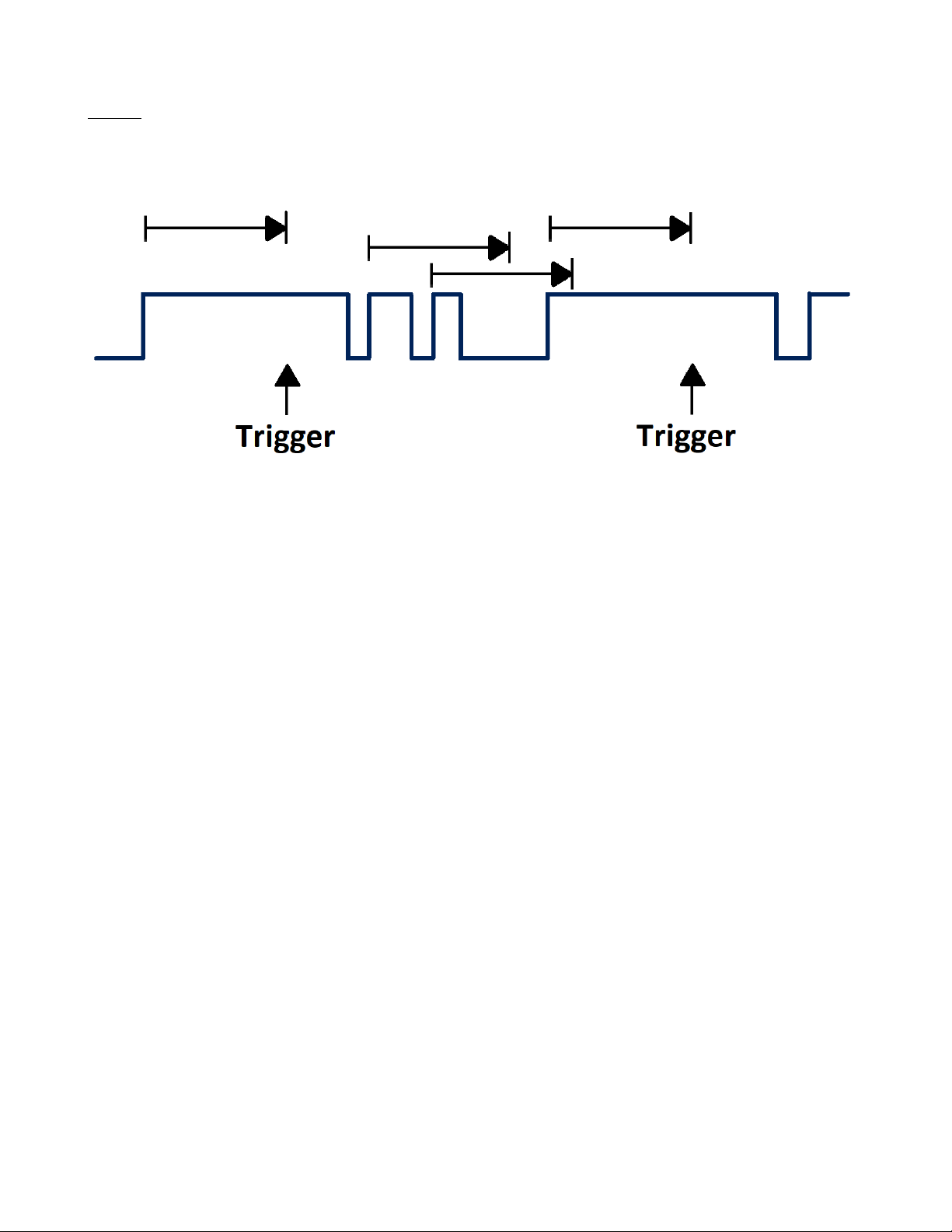
Trigger
66
State
Triggers when the signal enters or leaves a voltage level and stays there for a specified time. This is useful for detecting
when a signal gets stuck at a particular level.
Figure 9.19 Dropout Trigger State
To select
State Dropout Trigger
type:
1.
Press the Setup key or use the touchscreen controls to enter the
Trigger Menu.
2.
Use the touchscreen to select
Type .
3.
The window shown in figure
9.3
will appear.
– Use the touchscreen to select
Dropout.
4.
Use the touchscreen to set the
Over Time Type
to
State .
5. Use the touchscreen to toggle the
Slope
between
Rising
and
Falling.
Trigger source, slope (rising, falling), dropout type and time value can be set in the trigger dialog box. Holdoff, coupling,
and noise reject can be set in edge trigger, see the sections
Holdoff, Trigger Coupling
and
Noise Reject
for more
details.
Find Quality Products Online at: sales@GlobalTestSupply.com
www.GlobalTestSupply.com
Page 67

Trigger
67
9.2.8 Runt Trigger
The runt trigger detects a pulse that crosses the first threshold but not the second. It can occur when a logic driver has
insufficient slew rate to reach a valid logic level in the time available.
Figure 9.20
Runt Trigger
•
A positive runt pulse crosses through a lower threshold but not an upper threshold.
•
A negative runt pulse crosses through an upper threshold but not a lower threshold.
To select
Runt Trigger
type:
1.
Press the Setup key or use the touchscreen controls to enter the
Trigger Menu.
2.
Use the touchscreen to select
Type .
3.
The window shown in figure
9.3
will appear.
– Use the touchscreen to select
Runt.
4. Use the touchscreen to toggle the
Polarity
between
Positive
and
Negative.
5.
Use the touchscreen to select the
Limit Range.
•
<= (less than a time value)
: Trigger when the positive or negative slope time of the input signal is lower than
the specified time value.
•
>= (greater than a time value)
: Trigger when the positive or negative slope time of the input signal is greater
than the specified time value.
•
[- - . - -] (within a range of time value)
:Trigger when the positive or negative slope time of the input signal
is greater than the specified lower limit of time and lower than the specified upper limit of time value.
•
- -][- - (outside a range of time value)
: Trigger when the positive or negative slope time of the input signal is
greater than the specified upper limit of time and lower than the specified lower limit of time value.
Holdoff, coupling, and noise reject can be set in edge trigger, see the sections
Holdoff, Trigger Coupling
and
Noise
Reject for more details.
Find Quality Products Online at: sales@GlobalTestSupply.com
www.GlobalTestSupply.com
Page 68

Trigger
68
9.2.9 Pattern Trigger
The Pattern trigger identifies a trigger condition by looking for a specified pattern. The pattern trigger can be expanded
to incorporate delays.
Pattern durations are evaluated using a timer. The timer starts on the last edge that makes the pattern “true”. Potential
triggers occur on the first edge that makes the pattern false, provided that the time qualifier criterion has been met.
The oscilloscope provides 4 patterns: logical AND, OR, NAND and NOR combination of the channels. Each channel
can set to low, high or invalid.
Figure 9.21
Pattern Trigger
To select
Pattern Trigger
type:
1.
Press the Setup key or use the touchscreen controls to enter the
Trigger Menu.
2.
Use the touchscreen to select
Type .
3.
The window shown in figure
9.3
will appear.
–
Use the touchscreen to select
Pattern.
4.
Use the touchscreen to select the
Logic
pattern.
5.
Press the
Source Setting
to assign one of the following to each channel:
Don’t care, High
or
Low.
–
When digital channels are turned on, the logic state of the digital channel can also be set in the source setting
dialog box.
Find Quality Products Online at: sales@GlobalTestSupply.com
www.GlobalTestSupply.com
Page 69

Trigger
69
Logic Settings of Analog Channels Logic Settings of Digital Channels
Figure 9.22
Source Setting
•
Low: Sets the pattern to low on the selected channel. A low is a voltage level that is less than the channel’s
trigger level or threshold level.
•
High sets the pattern to high on the selected channel. A high is a voltage level that is greater than the channel’s
trigger level or threshold level.
•
Don’t care sets the pattern to don’t care on the selected channel. Any channel set to don’t care is ignored and is
not used as part of the pattern.
– If all channels in the pattern are set to
Don’t care
, the oscilloscope will not trigger.
6.
Use the touchscreen to select the
Limit Range.
•
When the logic is AND or NOR, the time limit condition is available. This setting is particularly useful to filter
the hazard signals of combinational logic.
•
When the logic is
OR
or
NAND
, the time limit setting is not supported.
Holdoff, coupling, and noise reject can be set in edge trigger, see the sections
Holdoff, Trigger Coupling
and
Noise
Reject for more details.
Find Quality Products Online at: sales@GlobalTestSupply.com
www.GlobalTestSupply.com
Page 70

Trigger
70
Note:
9.3 Trigger Mode
The oscilloscope’s trigger mode includes Auto, Normal, and Single. Trigger mode affects the way in which the oscilloscope
searches for the trigger.
After the oscilloscope starts running, the oscilloscope operates by first filling the pre-trigger buffer. It starts searching
for a trigger after the pre-trigger buffer is filled and continues to flow data through this buffer while it searches for the
trigger. While searching for the trigger, the oscilloscope overflows the pre-trigger buffer and the first data put into the
buffer is first pushed out (First Input First Out, FIFO).
When a trigger is found, the pre- trigger buffer contains the events that occurred just before the trigger. Then, the
oscilloscope fills the post- trigger buffer and displays the acquisition memory.
To select the trigger mode, press the key corresponding to the desired mode.
Auto
If the specified trigger conditions are not found, the triggers are forced and acquisitions are made so that signal activity
is displayed on the oscilloscope.
Auto
trigger mode is appropriate when:
•
Checking DC signals or signals with unknown levels or activity.
•
When trigger conditions occur often enough that forced triggers are unnecessary.
Normal
Triggers and acquisitions only occur when the specified trigger conditions are found. Otherwise, the oscilloscope holds
the original waveform and waits for the next trigger.
Normal
trigger mode is appropriate when:
•
Only specific events specified by the trigger settings are to be acquired.
•
Triggering on an infrequent signal from a serial bus such as I2C, SPI, CAN, LIN, etc. or another signal that arrives
in bursts.
Normal trigger mode stabilizes the display by preventing the oscilloscope from auto-triggering.
Single
The oscilloscope waits for a trigger and displays the waveform when the trigger condition is met, the acquisition is stopped
when the trigger conditions are met.
Single
trigger mode is appropriate when:
•
Capturing a single event or a periodic signal.
•
Capturing a burst or other unusual signals.
Find Quality Products Online at: sales@GlobalTestSupply.com
www.GlobalTestSupply.com
Page 71

Trigger
71
The oscilloscope can be forced to trigger by pressing the Single button twice. The trigger status in the upper right
corner of the screen will be displayed as "Stop".
9.4 Trigger Level
Trigger level and slope define the trigger point.
Figure 9.23
Trigger Point
To set the trigger level:
•
Use the touchscreen controls to open the
Trigger
dialog by pressing the trigger descriptor box.
Figure 9.24
Trigger
Descriptor Box
–
Press the
Level
box to set the trigger level by the virtual keypad. (Figure ??)
– Press
to increase and to decrease the trigger level scale.
The position of the trigger level for the analog channel is indicated by the trigger level icon (if the analog channel is
on). The value of the analog channel trigger level is displayed in the upper- right corner of the trigger descriptor box.
The example in figure
9.23
highlights the Positive edge slope at a trigger level of 100 mV.
Note:
Find Quality Products Online at: sales@GlobalTestSupply.com
www.GlobalTestSupply.com
Page 72

Trigger
72
9.5 Trigger Coupling
Trigger coupling is only valid when the trigger source is set to an analog channel, EXT or EXT/5.
Figure 9.25 Trigger
Coupling
To set the trigger coupling:
1.
Press the Setup key or use the touchscreen controls to enter the
Trigger
menu.
2.
Use the touchscreen controls to select the
Coupling
option.
– The window shown in figure
9.25
will appear.
3.
Use the touchscreen controls to select the desired coupling.
Trigger coupling is separate from channel coupling.
The oscilloscope provides 4 kinds of trigger coupling modes:
DC
Allows both AC and DC components of the waveform into the trigger path.
AC
Blocks all the DC components and attenuate signals lower than 8 Hz. Use AC coupling to get a stable edge trigger when
your waveform has a large DC offset.
LF Reject
The signal is coupled through a capacitive high-pass filter network, DC is rejected and low frequencies are attenuated.
For stable triggering on medium to high-frequency signals. See the Specifications for details of the cut-off frequency.
HF Reject
Signals are DC coupled to the trigger circuit and a low-pass filter network attenuates high frequencies (used for triggering
on low frequencies). See the Specifications for details of the cut-off frequency.
Note:
Find Quality Products Online at: sales@GlobalTestSupply.com
www.GlobalTestSupply.com
Page 73

Trigger
73
9.6 Trigger Holdoff
Trigger holdoff can be used to add an additional, user-defined delay to the re-arming of the trigger circuit. This provides
control over how rapidly, or how often, the oscilloscope can be triggered. The oscilloscope will not trigger until the
holdoff time expires.
Use the holdoff to trigger on repetitive waveforms that have multiple edges (or other events) between waveform repetitions.
You can also use holdoff to trigger on the first edge of a burst when you know the minimum time between bursts.
9.6.1 Holdoff by Time
Holdoff time is the amount of time that the oscilloscope waits before rearming the trigger circuitry. The oscilloscope will
not trigger until the holdoff time expires.
Use the holdoff to trigger on repetitive waveforms that have multiple edges (or other events) between waveform repetitions.
You can also use holdoff to trigger on the first edge of a burst when you know the minimum time between bursts.
For example, to achieve a stable trigger on the repetitive pulses shown in the figure below set the holdoff time (t) to 200
ns < t < 400 ns.
Figure 9.26
Holdoff
9.6.2 Holdoff by Event
The holdoff event is the number of events that the oscilloscope counts before re-arming the trigger circuitry. The
oscilloscope will not trigger until the counter tracking holdoff events reaches the set value.
Finding the Repetition of a Waveform
To find the repetition of the waveform:
1.
Press the Stop key to stop data acquisition.
2.
Turn the Horizontal Position Knob and the Horizontal Scale Knob to find where the waveform repeats.
3.
Measure the time using the cursors function.
4.
Set the
Holdoff
time.
Find Quality Products Online at: sales@GlobalTestSupply.com
www.GlobalTestSupply.com
Page 74

Trigger
74
Setting Holdoff
Figure 9.27 Trigger Holdoff
To set the trigger Holdoff:
1.
Press the Setup key or use the touchscreen controls to enter the
Trigger
menu.
2.
Use the touchscreen controls to select the
Holdoff
option.
– The window shown in figure
9.27
will appear.
3.
Use the touchscreen controls to select the desired Holdoff.
4.
Use the touchscreen controls to select
Holdoff Events
or
Holdoff Time
depending of the trigger holdoff that was selected.
Holdoff Events
Holdoff Time
Figure 9.28
Trigger Holdoff
–
The holdoff events of the oscilloscope is adjustable from 1 to 100000000
events.
–
The holdoff time of the oscilloscope is adjustable from 8 ns to 30 s.
5.
Use the virtual keypad or the
Universal knob
to adjust the number of hold-
off events or the holdoff time.
Adjusting the time scale and horizontal position will not affect the holdoff time.
9.6.3 Start Holdoff On
Start Holdoff On
defines the initial position of holdoff.
The 2560B series offers the following start holdoff on options:
Acq Start
: The initial position of holdoff is the first time point satisfying the trigger condition. In the example above,
each holdoff starts from the first rising edge of the pulse sequence.
Last Trig Time: The initial position of holdoff is the time of the last trigger. In the example above, the last trigger
position is at the second rising edge of the pulse sequence and the second holdoff starts from that point.
Note:
Find Quality Products Online at: sales@GlobalTestSupply.com
www.GlobalTestSupply.com
Page 75

Trigger
75
Setting Start Holdoff On
Figure 9.29 Start Hold-
off On
To set the start holdoff on:
1.
Press the Setup key or use the touchscreen controls to enter the
Trigger
menu.
2.
Use the touchscreen controls to select the
Start Holdoff On
option.
– The window shown in figure
9.29
will appear.
3.
Use the touchscreen controls to select the desired start holdoff on.
9.7 Noise Reject
Noise Rejection
adds additional hysteresis to the trigger circuitry. By increasing the trigger hysteresis band, the possibility
of triggering on noise is decreased, however the trigger sensitivity is also decreased. A larger signal is required to trigger
the oscilloscope when Noise Rejection is enabled.
To enable
Noise Rejection:
To set the start holdoff on:
1.
Press the Setup key or use the touchscreen controls to enter the
Trigger
menu.
2.
Use the touchscreen controls to select the
Noise Reject
option.
– Tapping
Noise Reject
will toggle between the on and off mode.
Disabled Enabled
Figure 9.30
Noise Reject
If the signal being probed is noisy, set up the oscilloscope to reduce the noise in the trigger path and on the displayed
waveform. First, stabilize the displayed waveform by removing the noise from the trigger path. Second, reduce the noise
on the displayed waveform.
•
Obtain a stable display.
•
Remove the noise from the trigger path setting Trigger coupling to LF Reject,
HF Reject
, or enabling
Noise Reject.
•
Set the Acquisition mode to
Average
to reduce noise.
Find Quality Products Online at: sales@GlobalTestSupply.com
www.GlobalTestSupply.com
Page 76
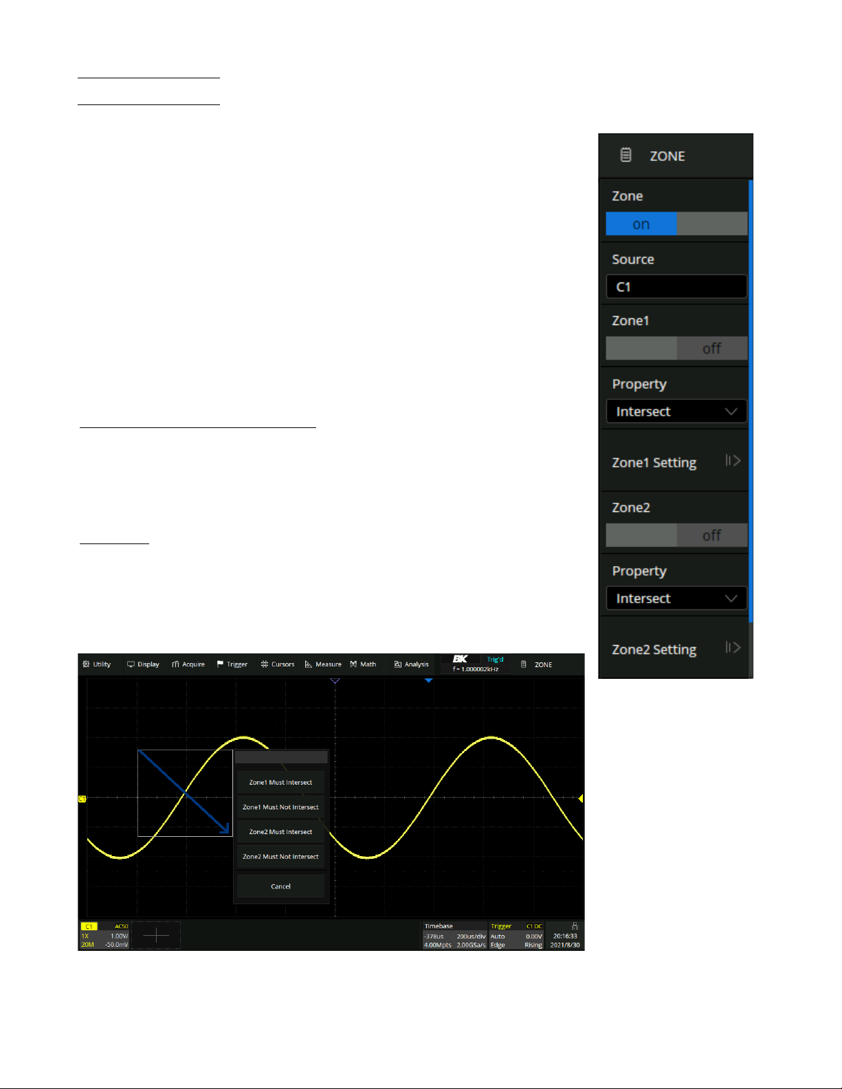
Trigger
76
9.8 Zone Trigger
The 2560B Series includes a zone trigger to help isolate elusive glitches. There are
two user-defined areas: Zone1 and Zone2. The property of each zone as
intersect
or
not intersect
as an additional condition to further isolate an event.
Intersect
only
includes events that occur within the zone.
Not intersect
includes all events that
occur
outside of the zone.
To enable and the trigger zone function:
1.
Press the Setup key or use the touchscreen controls to enter the
Trigger Menu.
2.
Use the touchscreen to select
Zone .
3.
The menu shown in figure
9.32
will appear.
4.
Press the
Zone
option to toggle the zone function on or off.
9.8.1 Creating and Moving Zones
The zones can be created and moved by gestures or by setting the zone settings in the
Zone Setting Menu. The color of the zone’s outline is consistent with the color of the
specified source.(Channel 1 = Yellow, etc.)
Gestures
When the zone trigger is turned on , touch-and-hold on any position within the waveform area and draw a rectangular box, as shown in figure 9.31.
When the finger moves out of the screen, a menu pops up for selecting the zone and
setting the zone properties:
Figure 9.31
Zone Gesture
Figure 9.32
Zone Trigger Menu
Find Quality Products Online at: sales@GlobalTestSupply.com
www.GlobalTestSupply.com
Page 77

Trigger
77
Note:
Once a zone is created, it can be moved by dragging. Touch and hold the zone box and use a dragging gesture to
reposition the zone.
Figure 9.33
Intersect Zone
Select C1 as the source, turn on zone1, and set the
property as Intersect.
Figure 9.34 Not Intersect Zone
Change
Intersect
to
Not Intersect
and use the drag
gesture to reposition the zone.
Menu Configuration
Figure 9.35
Region Setting
Zones can be also be configured using the
Region Setting
dialog box.
To configure the zone from the menu:
1.
Press the Setup key or use the touchscreen controls to enter the
Trigger Menu.
2.
Use the touchscreen to select
Zone .
3.
The menu shown in figure
9.32
will appear.
4.
Press the
Zone1 Setting
option to configure zone 1 or press the
Zone2 Setting
option to configure zone 2.
5.
The
Region Setting
menu shown in figure
9.35
allows for adjustments of the
available axes.
The axis value can be set using the virtual keypad or the
Universal Knob.
If zone1 and zone2 are both turned on, the result of the "AND"
operation in two zones becomes the qualifying condition of triggering.
Figure
9.37
demonstrates an example in which a waveform of bus contention is captured. With a simple edge trigger, it
is unlikely to trigger consistently on this anomaly.
Find Quality Products Online at: sales@GlobalTestSupply.com
www.GlobalTestSupply.com
Page 78

Trigger
78
Enabling the persistence display, allows the verification of bus contention occurring as shown in figure
9.36.
Figure 9.36
Persistence Enabled
Using the zone trigger is a quick and simple way to capture the interesting waveform.
Figure 9.37
Bus Waveform
Find Quality Products Online at: sales@GlobalTestSupply.com
www.GlobalTestSupply.com
Page 79

Serial Trigger and Decode
The 2560B series supports serial bus triggering and decoding on the following serial bus protocols:
I2C, SPI, UART,
CAN and LIN
and also support optional
FlexRay, CAN FD, I2S, MIL-STD-1553B, SENT and Manchester.
This chapter introduces the method of triggering and decoding these serial signals in details.
Figure 10.1
Bus Protocols
To select
Serial Trigger
type:
1.
Press the Setup key or use the touchscreen controls to enter the
Trigger Menu.
2.
Use the touchscreen to select
Type .
3.
The window shown in figure
9.3
will appear.
– Use the touchscreen to select
Serial.
4.
Use the touchscreen to select
Protocol.
–
The dropdown menu shown in figure
10.1
will appear.
5.
Select the desired bus protocol.
To select the decoding
Bus Protocol:
1.
Press the Decode key or use the touchscreen controls to enter the
Decode Menu.
2.
Use the touchscreen to enable
Bus Operation.
3.
Use the touchscreen to select
Bus Protocol.
4.
The window shown in figure
10.1
will appear with the addition of the
Manchester
protocol.
5.
Select the desired bus protocol.
10.1 I2C Trigger and Serial Decode
10.1.1 Setup for I2C Signals
To set the I2C (Inter-IC bus) signal first, connect the serial data signal (SDA) and serial clock signal (SCL) to oscilloscope.
Set the mapping relation between channels and signals and then set the threshold level of each signal.
To set I2C decoding:
1.
Press the Decode key to enter the
Decode
menu.
2.
Use the touchscreen to press the
Bus Protocol
option and select
I2C.
3.
Use the touchscreen to press the
Protocol Signals
option.
–
The
I2C Signal
menu shown in figure
10.2
will be displayed.
Find Quality Products Online at: sales@GlobalTestSupply.com
www.GlobalTestSupply.com
Page 80

Serial Trigger and Decode
80
Figure 10.2 I2C Signal Menu
4.
Set the source of SCL. In the example shown in figure
10.2
, SCL is connected to C2.
5.
Set the threshold level of SCL. It is 750 mV for the LVTTL signal in this example.
6.
Set the source of SDA. In the example above, SDA is connected to C1.
7.
Set the threshold level of the SDA channel.
–
The threshold voltage level is for decoding, and it will be regarded as the trigger voltage level when the trigger
type is set to serial.
–
Threshold level line. It only appears when adjusting the threshold level.
8.
Touch
option to return previous menu.
The signal settings of decoding and triggering are independent. To
synchronize the settings between decode and trigger, perform the
Copy Setting function in the Decode menu.
1.
Touch
Protocol Copy
in the Decode menu to synchronize the
settings between the trigger and decoding configurations.
2.
Copy the decode settings to trigger.
3.
Copy the trigger settings to decode.
4.
Touch
option to return previous menu.
Figure 10.3
Decode Setting Menu
Find Quality Products Online at: sales@GlobalTestSupply.com
www.GlobalTestSupply.com
Page 81

Serial Trigger and Decode
81
Note:
10.1.2 I2C Trigger
The I2C trigger has nine trigger conditions: (
Start, Stop, Restart, No Ack, EEPROM, 7 Addr&Data, 10 Addr&Data
and Data Length)
•
Start Condition
: The oscilloscope will be triggered when the SDA signal transitions from high to low while the SCL
clock is high. If it is chosen as the condition of trigger (including frame triggers), a restart will be treated as a “Start
condition”.
•
Stop Condition
: The oscilloscope will be triggered when SDA transitions from low to high while the SCL is high.
Figure 10.4 Start and Stop Conditions
•
Restart
: The oscilloscope will be triggered when another “Start condition” occurs before a “Stop condition”.
•
No Ack
: The oscilloscope will be triggered when SDA data is high during any SCL’s ACK bit.
•
EEPROM
: The trigger searches for EEPROM control byte (the value is 1010xxx) on the SDA bus where there is a
Read bit and an ACK bit behind EEPROM.
–
Use the
Limit Range
to set the qualifier.
–
Use the
Data1
to set the data’s value.
If EEPROM’s data is greater than Data1, the oscilloscope will be triggered at the edge of ACK
bit behind Data byte. It’s unnecessary that the Data byte musts follow the EEPROM.
Figure 10.5
Trigger Point
•
7 address & Data
: The oscilloscope will be triggered when the following conditions are satisfied:
–
The address’s length must be 7 bits and the address’s value must be the same as the set value.
–
Data1’s or Data2’s value is set to the same value of the signal’s data.
–
Both Data1’s and Data2’s values are set and the signal has two consecutive data values, the first is value is
Data1
and the second data value is Data2.
Find Quality Products Online at: sales@GlobalTestSupply.com
www.GlobalTestSupply.com
Page 82

Serial Trigger and Decode
82
Note:
If the data’s value is 0xXX, any data value will be matched.
Figure 10.6 7 Address & Data
•
10 address & Data
: The oscilloscope will be triggered when the following conditions are satisfied:
–
The address’s length must be 10 bits and the address’s value must be the same as the set value.
–
Data1’s or Data2’s value is set to the same value of the signal’s data.
–
Both Data1’s and Data2’s values are set and the signal has two consecutive data values, the first is value is
Data1
and the second data value is Data2.
–
R/W can be specified as Write, Read, or Don’t Care.
If the data’s value is 0xXX, any data value will be matched.
Figure 10.7 10 Address & Data
•
Data Length
: When SDA data’s length is equal to the value of Byte Length and address’s length is the same as set
value, the oscilloscope will be triggered. Byte length is in the range of 1 to 12 bits.
Note:
Find Quality Products Online at: sales@GlobalTestSupply.com
www.GlobalTestSupply.com
Page 83

Serial Trigger and Decode
83
Note:
Operation Step
1.
Touch Setup key or use the touchscreen controls to enter the
Trigger Menu.
2.
Use the touchscreen to select
Type .
3.
The window shown in figure
9.3
will appear.
– Use the touchscreen to select
Serial.
4.
Use the touchscreen to select
Protocol.
–
The dropdown menu shown in figure
10.1
will appear.
5.
Use the touchscreen to select
I2C
protocol.
6.
Use the touchscreen to select
Trigger Setting.
7.
Use the touchscreen to select
Conditions.
–
The dropdown menu shown in figure
10.8
will be displayed.
–
Select the desired condition.
Figure 10.8
I2C Conditions
•
If EEPROM is selected :
–
Touch
Limit Range
option to set the qualifier (
=, < or >).
–
Touch
Data1
and set its value by turning the
Universal Knob
or using the virtual keypad.
•
If 7 Addr & Data or 10 Addr & Data is selected:
–
Touch
Addr
option and turn the
Universal Knob
to select the 7- bit or 10- bit device address.
–
Touch
Data1
or
Data2
and set the value.
–
Touch
R/W bit
and select write-frame or read-frame to trigger the oscilloscope.
If the device’s address is 7-bit, the value of address is in range of 0x00 to 0x7F. If device’s address is 10-bit,
the value of address is in range of 0x00 to 0x3FF.
•
If
Data Length
is selected:
–
Touch
Address
to set the SDA address length 7bit or 10 bit.
–
Touch
Byte Length
and set the byte length by
Universal Knob
. The range of the Byte Length is 1 to 12.
Find Quality Products Online at: sales@GlobalTestSupply.com
www.GlobalTestSupply.com
Page 84

Serial Trigger and Decode
84
10.1.3 I2C Serial Decode
Once the setup for the I2C signal and trigger has been completed, the decoding operation must be setup.
1.
Touch Decode key to display the
Decode
menu.
2.
Use the touchscreen to enable the
Bus Operation.
3.
Touch
Bus
option to select either
Bus1
or
Bus2.
4.
Touch
Display
option to select the character encoding format of the decoding’s result.
–
The bus’s vertical position can be adjusted using the
Universal Knob
after selecting
Bus Position.
5.
Touch
to return to the
Decode
menu.
6.
Touch
Display
option and choose the bus option selected in step 3.
7.
Touch
Lines
options and set the number of lines by
Universal Knob
or the virtual keypad.
–
The range of the lines is 1 to 7.
8.
Touch
Scroll
option and turn the Universal Knob to navigate the available lines.
Interpreting the I2C Decode
The frames of decoding result:
•
The address value is displayed at the beginning of a frame. The write address is displayed in green, and the read
address is displayed in yellow.
•
W/R bit is represented by (W) and (R), following the address value.
•
The data value is displayed in white.
•
"˜A" after a data or address bits indicates no acknowledgement. For example, DB˜A.
•
A red dot indicates there is not enough space on the display to show the complete content of a frame.
Figure 10.9
I2C Decode Bus Display
The lists of decoding result:
•
Time
: The horizontal displacement between current frame and trigger position.
•
Address
: The address of a frame.
•
R/W
: The type of a frame (write or read).
•
Data
: The value of data.
Figure 10.10
Decode List Display
Find Quality Products Online at: sales@GlobalTestSupply.com
www.GlobalTestSupply.com
Page 85

Serial Trigger and Decode
85
10.2 SPI Trigger and Serial Decode
10.2.1 Setup for SPI Signals
Setting the SPI (Serial Peripheral Interface) signal includes two steps: Connecting the CLK, MISO, MISO and CS signal
to oscilloscope, specifying the parameters of each input signal.
1.
Touch Decode key to enter the
Decode
menu.
2.
Touch
Decode
and select the desired slot (
Decode1
or
Decode2).
3.
Touch
Protocol
to display the available SPI Signals.
4.
Set CLK (clock signal):
•
Touch CLK to enter CLK menu.
•
Touch
CLK
to select the channel that is connected to the SPI clock signal.
•
Touch
Threshold
to set the SPI clock signal’s threshold voltage level by Universal Knob.
–
The threshold voltage level is for decoding, and it will be regard as the trigger voltage level when set the
trigger type to serial.
•
Touch
Edge Select
to set the oscilloscope will samples at clock signal’s rising edge or falling edge.
•
Touch
to return previous menu.
5.
Set MISO:
•
Touch
MISO
to enter the
MISO
menu.
•
Touch
MISO
to select the channel that is connected to the SPI MISO signal.
•
Touch
Threshold
softkey, then use the
Universal Knob
to set the SPI MISO signal’s threshold voltage level.
–
The threshold voltage level is for decoding, and it will be regard as the trigger voltage level when set the
trigger type to serial.
•
Touch
to return to the previous menu.
6.
Set MOSI:
•
Press the
MOSI
to enter the MOSI menu.
•
Touch
MOSI
to select the channel that is connected to the SPI MOSI signal.
•
Press the
Threshold
softkey, then use the
Universal Knob
to set the SPI MOSI signal’s threshold voltage level.
– The threshold voltage level is for decoding, and it will be regarded as the trigger voltage level when the trigger
type is set serial.
•
Touch
to return to the previous menu.
7.
Set CS:
•
Touch
CS
to enter the MOSI menu.
•
Touch
CS Type
to select the chip select type.
•
Modify the CD value.
•
Touch
to return to the previous menu.
Find Quality Products Online at: sales@GlobalTestSupply.com
www.GlobalTestSupply.com
Page 86

Serial Trigger and Decode
86
Function Menu
Settings
Description
CS Type
˜CS
Low voltage level of CS signal is available
CS
High voltage level of CS signal is available
CLK Timeout
If the time between two edges of the clock signal is less than (or equal to)
the value of timeout, the signal between the two edges is treated as a frame.
The range of clock timeout is 100 ns - 5 ms.
This setting is suitable for case where the CS signal is not connected, or the
number of oscilloscope channels is insufficient (such as 2-channel
oscillo
scopes).
Table 10.1 CS Type Parameters
Example
Connect the data, CLK and ˜CS signals of a SPI bus respectively to C1, C2, and C3. Data width = 8-bit, Bit order =
MSB, CS polarity = CS, and 12 data bytes are transmitted in one frame.
In the SPI trigger signal menu, set the source and threshold of CLK, MISO and CS signals, then copy the trigger settings
to decoding. Adjust the timebase, so that the falling edge of the CS signal is shown in the display:
Figure 10.11
Example
Find Quality Products Online at: sales@GlobalTestSupply.com
www.GlobalTestSupply.com
Page 87

Serial Trigger and Decode
87
When the CS type is set to Clock Timeout, the clock idle time between frames is T3, the clock period is T1, then set
the timeout to a value between T1 and T3
Figure 10.12
Example 2
If the data width is set to be greater than 8 bits (such as 16 bits), the clock idle time between 8-bit data packets T2,
and then set the timeout time to a value between T1/2+T2 and T3.
Figure 10.13
Example 3
Find Quality Products Online at: sales@GlobalTestSupply.com
www.GlobalTestSupply.com
Page 88

Serial Trigger and Decode
88
10.2.2 SPI Trigger
This section provides a brief introduction for the operation of the SPI trigger.
1.
Press the
Setup
key to enter the
TRIGGER
function menu.
2.
Touch
Type
and select
Serial.
3.
Touch
Protocol
and select
SPI.
4.
Touch
Trigger Setting
softkey.
5.
Touch
Trigger Type
to select the trigger condition.
Function Menu
Settings
Explanation
Trigger Type
MISO
Master-In, Slave-Out
MOSI
Master-Out, Slave-In
Table 10.2 SPI Trigger Type
6.
Touch Data Length and turn the Universal Knob to set the length of a data. The range of data length is 4 to 96
bits.
7.
Set the value of the trigger data.
•
Set the value of a bit:
a.
Touch
Bit Roll
to select a bit in data.
b.
Touch
Bit Value
to set the value of the selected bit.
•
Set the value of all bits:
a. Touch
All Same
to set the value of all bits.
Function Menu
Settings
Explanation
Bit Value
0
High voltage level
1
Low voltage level
X
Don’t care the voltage level
Table 10.3 SPI Bit Value
8.
Touch Bit Order to set the bit order (MSB or LSB).
Find Quality Products Online at: sales@GlobalTestSupply.com
www.GlobalTestSupply.com
Page 89

Serial Trigger and Decode
89
10.2.3 SPI Serial Decode
Once the setup of SPI signal and trigger is complete, the SPI signals can be decoded.
Operation steps as follows:
1.
Touch
Decode –>Decode
. Select one of the options from the
Decode1
and
Decode2.
2.
Press the
Display
key and select
On
to display the result of decoding.
3.
Touch
List
to enter the
LIST
function menu.
4.
Touch
Display
and choose the same options as the first step.
5.
Touch Lines and set the number of lines by
Universal Knob
. The range of the lines is 1 to 7.
6.
Touch
Format
to change the character encoding format of the decoder’s result.
7.
Touch
Scroll
and turn the
Universal Knob
to view all frames.
Interpreting SPI Decode
The frames of decoding result:
•
The data values are displayed in frames and are shown in white. Support 4 96-bit data display.
•
MISO
— the decoding result of “Master-In, Slave-Out” line.
•
MOSI
— the decoding result of “Master-Out, Slave-In” line.
• Indicates there is not enough space on the display to show the complete content of a frame, and some content is
hidden.
Figure 10.14 SPI Decode Bus Display
The lists of decoding result:
•
Time
— the horizontal displacement between current frame and trigger position.
•
MISO
— the decoding result of “Master-In, Slave-Out” line.
•
MOSI
— the decoding result of “Master-Out, Slave-In” line.
Figure 10.15 SPI Decode List Display
Find Quality Products Online at: sales@GlobalTestSupply.com
www.GlobalTestSupply.com
Page 90

Serial Trigger and Decode
90
10.3 UART Trigger and Serial Decode
10.3.1 Setup for UART Signals
1.
Press the
Decode
key to enter the
DECODE
menu.
2.
Touch
Decode
and select the desired slot (Decode1 or Decode2).
3.
Touch
Protocol
and then select
UART
by turning
Universal Knob.
4.
Touch
Signal
to enter the
SIGNAL
menu as below shows.
5.
Set RX:
a.
Touch
RX
to select the channel that is connected to the RX signal.
b.
Touch first
Threshold
key to set the RX signal’s threshold voltage level by
Universal Knob
. The threshold
voltage level is for decoding, and it will be regard as the trigger voltage level when set the trigger type to serial.
6.
Set TX:
a.
Touch TX to select the channel that is connected to the TX signal.
b.
Touch second Threshold key to set the TX signal’s threshold voltage level by Universal Knob. The threshold
voltage level is for decoding, and it will be regard as the trigger voltage level when set the trigger type to serial.
7.
Touch
to return previous menu.
8.
Touch
Configure
to enter
BUS CONFIG
menu.
9.
Touch
Baud
to set baud rate.
•
The baud rate can be set as predefined value.
•
If the desired baud rate is not listed, press the
Baud
and select custom option, press the
Custom
and turn the
Universal Knob
to set the desired baud rate.
10.
Touch
Data Length
and set byte bits (5-8) by
Universal Knob.
11.
Touch
Parity Check
to set the type of parity check (
Even, Odd, Mark, Space
or
None).
12.
Touch
Stop Bit
to set the length of stop bit (1, 1.5 or 2 bits).
13.
Touch
Next Page
softkey.
14.
Touch Bit Order to select the bit order (LSB or MSB).
15.
Touch
Idle Level
to set the idle level (
LOW
or
HIGH).
Find Quality Products Online at: sales@GlobalTestSupply.com
www.GlobalTestSupply.com
Page 91

Serial Trigger and Decode
91
10.3.2 UART Trigger
This section includes an introduction and description for the operation of the UART trigger.
1.
Touch
Setup
key to enter the
TRIGGER
function menu.
2.
Touch
Type
and select
Serial.
3.
Touch
Protocol
and select
UART.
4.
Touch
Trigger Setting
to enter
UART TRIG SET
menu.
5.
Touch
Source Type
to select the source of trigger (RX or TX).
6.
Touch
Condition
and set up the desired trigger condition:
•
Start
— the oscilloscope will be triggered at the position of start bit.
•
Stop
—the oscilloscope will be triggered at the position of stop bits.
•
Data
— the oscilloscope will be triggered when found a byte which is equal to (greater or less than) the specified
data.
a.
Touch
Compare Type
and choose an equality qualifier (>, < or =).
b.
Touch
Value
to set data’s value. Data’s value is in range of 0x00 to 0xff.
•
ERROR
— if the parity check has been set, and the bit of parity check is error, the oscilloscope will be triggered.
Figure 10.16 UART Trigger
Find Quality Products Online at: sales@GlobalTestSupply.com
www.GlobalTestSupply.com
Page 92
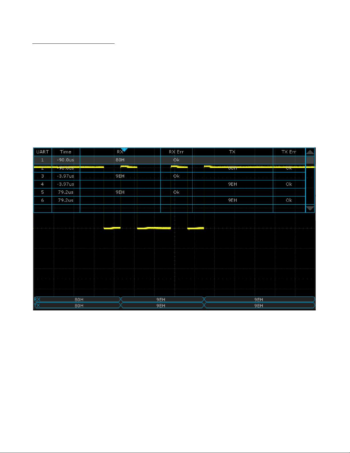
Serial Trigger and Decode
92
10.3.3 UART Serial Decode
Upon completing the setup of UART signal and trigger, the UART signals can be decoded. Operation steps as follows:
1.
Press
Decode
–>
Decode
. Select one of the options from the
Decode1
and Decode2.
2.
Touch
Display
and select
On
to display the result of decoding.
3.
Touch
List
to enter the
LIST
function menu.
4.
Touch
Display
key and choose the same options as the first step.
5.
Touch
Lines
and set the number of lines by
Universal Knob
. The range of the lines is 1 to 7.
6.
Touch
Format
softkey to change the character encoding format of the decoding’s result.
7.
Turn the
Universal Knob
to view all frames.
Figure 10.17 UART Decode
Find Quality Products Online at: sales@GlobalTestSupply.com
www.GlobalTestSupply.com
Page 93

Serial Trigger and Decode
93
Interpreting UART Decode
The frames of decoding result:
•
RX
— the decoding result of the data received.
•
TX — the decoding result of the data transmitted.
• Indicates there is not enough space on the display to show the complete content of a frame, and some content is
hidden.
Figure 10.18 UART Decode Bus Display
The lists of decoding result:
•
Time
— the horizontal displacement between current frame and trigger position.
•
RX
— the receiving channel.
•
TX — the transmitting channel.
•
RX Err
— Parity error or unknown error in the data received.
•
TX Err
— Parity error or unknown error in the data transmitted.
Figure 10.19 UART Decode List Display
Find Quality Products Online at: sales@GlobalTestSupply.com
www.GlobalTestSupply.com
Page 94

Serial Trigger and Decode
94
10.4 CAN Trigger and Serial Decode
Placed in order of
Setup for CAN Signals, CAN Trigger and, CAN Serial Decode”
to trigger and decode the signals.
10.4.1 Setup for CAN Signals
1.
Touch
Decode
key to enter the
DECODE
function menu.
2.
Touch
Decode
and select the desired slot (Decode1 or Decode2).
3.
Touch
Protocol
and then select
CAN
by turning Universal Knob.
4.
Touch
Signal
to enter the
SIGNAL
menu as shown in figure ??.
a.
Touch
Source
to select the channel that is connected to the CAN signal.
b.
Touch
Threshold
key to set the CAN signal’s threshold voltage level by
Universal Knob
. The threshold voltage
level is for decoding, and it will be regard as the trigger voltage level when set the trigger type to serial.
5.
Touch
Configure
to enter the
BUS CONFIG
menu.
6.
Touch
Baud
to set baud rate by rotating the
Universal Knob.
•
The baud rate can be set as predefined value (from 5kb/s to 1Mb/s) or custom value (from 5kb/s to 1Mb/s).
•
If the desired baud rate is not listed, press
Baud
and select the
custom
option, press the
Custom
and turn the
Universal Knob
to set the desired baud rate.
10.4.2 CAN Trigger
This section provides a brief introduction and description for the operation of the CAN trigger.
Trigger Conditions
•
Start
— the oscilloscope will be triggered at the start bit of a frame.
•
Remote
— the oscilloscope will be triggered by a remote frame with specified ID.
•
ID
— the oscilloscope will be triggered by a remote or data frame that have specified ID.
•
ID+DATA
— the oscilloscope will be triggered by data frame that have specified ID and data.
•
Error
— the oscilloscope will be triggered by an error frame.
Find Quality Products Online at: sales@GlobalTestSupply.com
www.GlobalTestSupply.com
Page 95

Serial Trigger and Decode
95
Operation Steps
1.
Touch
Setup
to enter the
TRIGGER
function menu.
2.
Touch
Type
and select
Serial.
3.
Touch
Protocol
and select
CAN.
4.
Touch
Trigger Setting
to enter the
CAN TRIG SET
menu.
5.
Touch
Condition
and select the trigger condition by turning the
Universal Knob:
•
If you select the
REMOTE
and
ID
condition:
a.
Touch
ID Bits
to set the length of ID (11bits or 29 bits).
b.
Touch
Curr ID Byte
and turn the
Universal Knob
to select the byte that you want to set.
c.
Touch
ID
and set the ID’s value by turning the
Universal Knob
. (Tips: In order to make is convenient for
the operator to set the parameters, ID b is split into several bytes. For example, if the ID’s length is 11 bits,
it will be split into two bytes, a byte includes 8 bits. If “1st byte” is selected, only the 8 least significant bits
can be changed.)
•
If you select the
ID+DATA
condition:
a.
Touch
ID
bits to select the ID’s length (11 or 29 bits).
b.
Touch
Curr ID Byte
and turn the
Universal Knob
to select the byte that you want to modify.
c.
Touch
ID
and set the ID’s value by turning the
Universal Knob.
d.
Touch
Data
and set the value of the first byte by turning the
Universal Knob.
Figure 10.20 CAN Trigger
10.4.1 CAN Serial Decode
Upon completing the setup of can signal and trigger, the CAN signals can be decoded.
1.
Press
Decode
–>
Decode
. Select one of the options from the Decode1 and Decode2.
2.
Touch
Display
and select
On
to display the result of decoding.
3.
Touch
List
to enter the
LIST
function menu.
4.
Touch
Display
and choose the same options as the first step.
5.
Touch
Lines
and set the number of lines by
Universal Knob
. The range of the lines is 1 to 7.
Find Quality Products Online at: sales@GlobalTestSupply.com
www.GlobalTestSupply.com
Page 96
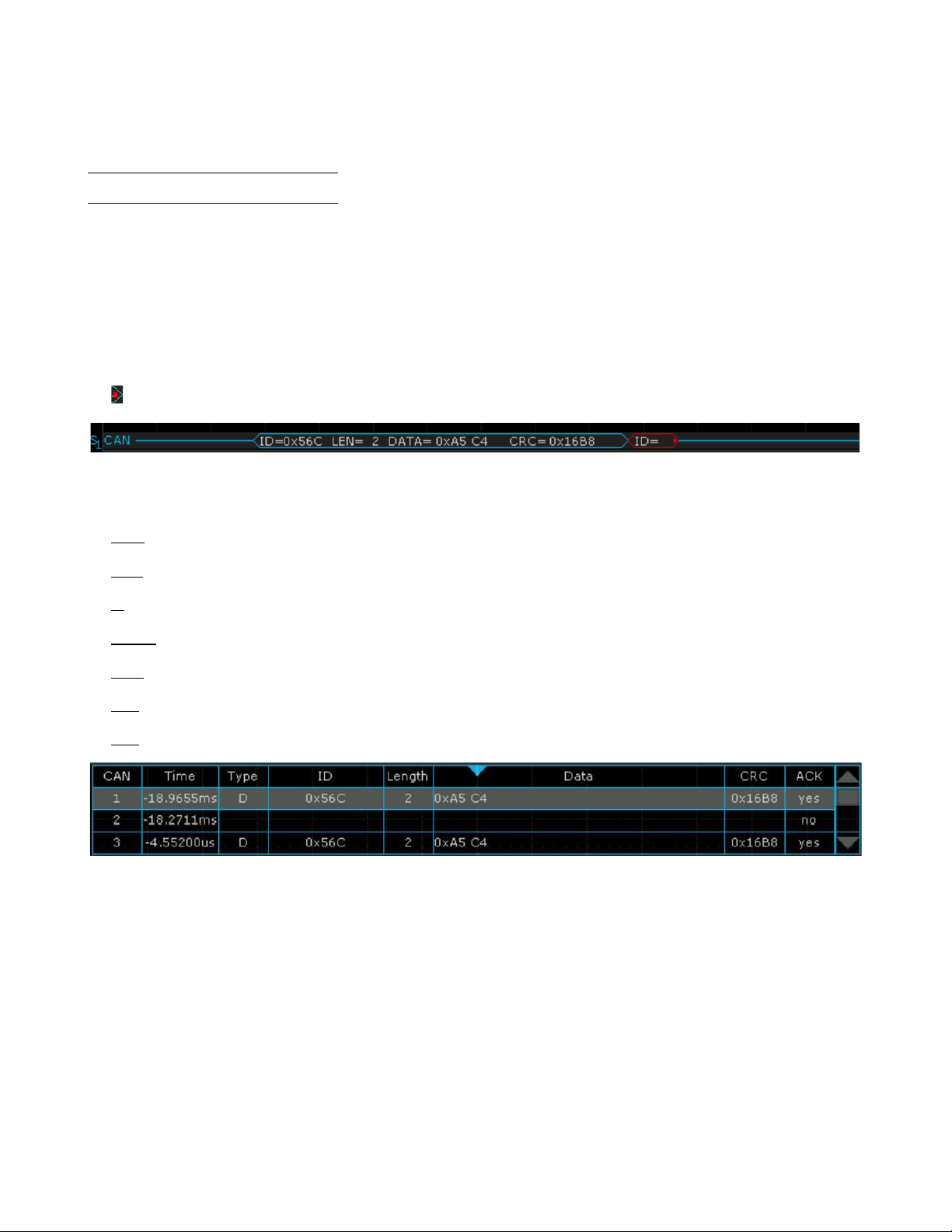
Serial Trigger and Decode
96
6.
Touch
Format
softkey to change the character encoding format of the decoder’s result.
7.
Touch
Scroll
and turn the
Universal Knob
to view all frames.
Interpreting CAN Decode
The frame of decoding result:
•
Arbitration field is displayed in frame
•
Control field is displayed in frame
•
Data field is displayed in frame
•
CRC field is displayed in frame
• Indicates there is not enough space on the display to show complete content of a frame and some content is hidden.
Figure 10.21 CAN Decode Bus Display
The list of decoding result:
•
Time
— the horizontal displacement between current frame and trigger position.
•
Type
— the type of frames, “D” represents data frame, “R” represents remote frame.
•
ID
— the id of frames, the oscilloscope can automatically detect the length of frame’s id (11 bits or 27 bits).
•
Length
— the length of data field.
•
Data — the value of data field.
•
CRC — the value of CRC (Cyclic Redundancy Check) field.
•
ACK — Acknowledgment bit.
Figure 10.22 CAN Decode List Display
Find Quality Products Online at: sales@GlobalTestSupply.com
www.GlobalTestSupply.com
Page 97

Serial Trigger and Decode
97
Note:
10.5 LIN Trigger and Serial Decode
10.5.1 Setup for LIN Signals
There are two steps of setting the LIN signal, connecting the signal to oscilloscope, specifying the parameters of each
input signal.
1.
Press the
Decode
key to enter the
DECODE
function menu.
2.
Touch
Decode
and select the desired slot (Decode1 or Decode2).
3.
Touch
Protocol
and then select
LIN
by turning Universal Knob.
4.
Touch
Signal
to enter the
SIGNAL
menu as shown in figure ??.
5.
Touch
Source
to select the channel that is connected to the LIN signal.
6.
Touch
Threshold
and set the LIN signal’s threshold voltage level by
Universal Knob
. The threshold voltage level is
for decoding, and it will be regard as the trigger voltage level when set the trigger type to serial.
7.
Touch
to return previous menu.
8.
Touch
Configure
to enter the
BUS CONFIG
menu.
9.
Touch
Baud
to set baud rate.
•
The baud rate can be set as predefined value.
•
If the desired baud rate is not listed, select
custom
option, press the Custom and turn the
Universal Knob
to
set the desired baud rate.
10.5.2 LIN Trigger
This section provides a brief introduction and description for the operation of the LIN trigger.
Trigger Condition
•
Break
— the oscilloscope will be triggered at the position of break field’s break delimiter.
•
ID
(Frame ID) — the oscilloscope will be triggered at the position of identifier field’s stop bit, if the value of a frame’s
ID is equal to specified value. (Note: If the data’s value is 0xXX, any data value will be matched)
•
ID + Data
(Frame ID and Data) — the oscilloscope triggers when a frame with an ID and data equal to the selected
values is detected. Use the Universal Knob to select the value for the ID, Data1 and Data2.
a.
The ID’s value is the same as set value.
b.
If you have set either Data1’s or Data2’s value, and the signal has a data is the same as that value. If you have
set both Data1’s and Data2’s value, the signal should have two consecutive data, the first data’s value is Data1,
second data value is Data2.
If the data’s value is 0xXX, any data value will be matched
•
Data Error
—the oscilloscope will be triggered when errors (such as ID check error, checksum error, sync byte field
error) are detected.
Find Quality Products Online at: sales@GlobalTestSupply.com
www.GlobalTestSupply.com
Page 98

Serial Trigger and Decode
98
Operation Steps
•
Touch
Setup
key to enter the
TRIGGER
function menu.
•
Touch
Type
and select
Serial.
•
Touch
Protocol
and select
I2C.
•
Touch
Trigger Setting
to enter
LIN TRIG SET
menu.
•
Touch
Condition
and select the trigger condition by
Universal Knob:
•
If you select
ID
condition:
–
Touch
ID
and set its value by turning the
Universal Knob.
•
If you select
ID+DATA
condition:
–
Touch
ID
and set its value by turning the
Universal Knob.
–
Touch
DATA1
and set its value by turning the Universal Knob.
–
Touch
DATA2
and set its value by turning the Universal Knob.
Figure 10.23
LIN Trigger
Find Quality Products Online at: sales@GlobalTestSupply.com
www.GlobalTestSupply.com
Page 99

Serial Trigger and Decode
99
10.5.1 Interpreting LIN Decode
The frame of decoding result:
•
Protected Identifier Field is displayed in frame
•
Data Length is displayed in frame
•
Data Field is displayed in frame.
•
Checksum Field is displayed in frame.
• Indicates there is not enough space on the display to show complete content of a frame and some content is
hidden.
Figure 10.24 LIN Decode Bus Display
The list of decoding result:
•
Time
— the horizontal displacement between current frame and trigger position.
•
ID
— the value of frame’s Protected Identifier Field.
•
Data Length — the length of Data Field.
•
ID Parity
— the two check bits of Protected Identifier Field.
•
Data — the value of Data Field.
•
Checksum
— the value of Checksum Field.
Figure 10.25 LIN Decode List Display
Find Quality Products Online at: sales@GlobalTestSupply.com
www.GlobalTestSupply.com
Page 100

Serial Trigger and Decode
100
10.6 FlexRay Trigger and Serial Decode
This section covers triggering and decoding FlexRay signals. Please read the following
for more details:
FlexRay Signal Configuration, FlexRay Trigger
and
FlexRay Serial
Decode.
Before configuring the signal settings, connect the FlexRay signal to the oscilloscope.
10.6.1 FlexRay Signal Configuration
To select the decoding
Bus Protocol:
1.
Press the Decode key or use the touchscreen controls to enter the
Decode Menu.
2.
Use the touchscreen to enable
Bus Operation.
3.
Use the touchscreen to select
Bus Protocol.
4.
The window shown in figure
10.1
will appear with the addition of the
Manchester
protocol.
5.
Select the
FlexRay
bus protocol.
Protocol Signals
To set the source and threshold of the
FlexRay
signal use the touchscreen to select
Protocol Signal:
1.
The
FLX SIGNAL
menu will be displayed. (Figure
10.27)
2.
Use the touchscreen to select
Source
and select the source the signal is connected to.
3.
Use the touchscreen to select
Threshold
and input the desired threshold
–
The threshold voltage level is for decoding, and it will be regarded as the trigger
voltage level when the trigger type is set to serial.
–
The threshold level line only appears when adjusting the threshold level.
4.
Touch
option to return previous menu.
Protocol Config
To set the baud rate use the touchscreen to select
Protocol Config:
1.
The
FLX CONFIG
menu will be displayed. (Figure
10.28)
2.
Use the touchscreen to select
Baud
and set the baud rate.
– The baud rate can be set to 2.5 Mb/s, 5.0 Mb/s, 10.0 Mb/s or Custom.
3.
Touch
option to return previous menu.
Figure 10.26
Decode FlexRay Protocol
Figure 10.27
FlexRay Signal Menu
Figure 10.28
FlexRay
CONFIG
Find Quality Products Online at: sales@GlobalTestSupply.com
www.GlobalTestSupply.com
 Loading...