

Page 1
Model: 2540B, 2542B, 2540B-GEN,
USER MANUAL
2542B-GEN
Digital Storage
Oscilloscopes
Page 2

2 3
Page 3

Safety Summary
The following safety precautions apply to both operating and
maintenance personnel and must be observed during all phases
of operation, service, and repair of this instrument. Before
applying power, follow the insta lla tion instructions and become
familiar with the operating instr uctions for this instrument.
If this device is damaged or something is missing, contact the
place of purchase immediately.
This manual contains information and warnings that must be
followed to ensure safe operation as well as to maintain the
oscilloscope in a safe condition.
GROUND THE INSTRUMENT
To minimize shock hazard, the instrument chassis and cabinet
must be connected to an electrical gro und. This instrument is
grounded through the ground conductor of the supplied,
three-conductor ac power cable. The power cable must be
plugged into an approved three-conductor electrical outlet. Do
not alter the ground conne ction. Wi t hout the protective ground
connection, all accessible conductive parts (including control
knobs) can render an electric shock. The power jack and
mating plug of the power cable must meet IEC safety standards.
DO NOT OPERATE IN AN EXPLOSIVE ATMOSPHERE
Do not operate the instrument in the presence of flammable
gases or fumes. Operation of any electrical instrument in such
an environment constitutes a definite safety hazard.
Page 4

KEEP AWAY FROM LIVE CIRCUITS
Instrument covers must not be removed by operating personnel.
Component replacement and internal adjustments must be made
by qualified maintenance personnel. Disconnect the power
cord before removing the instrument covers and replacing
component s . Under cer tain conditions, even with the power
cable removed, dangerous voltages may exist. To avoid
injuries, always disconnect power and discharge circuits before
touching them.
DO NOT SERVICE OR ADJUST ALONE
Do not attempt any internal service or adjustment unl ess another
person, capable of rendering first aid and resuscitation, is
present.
DO NOT SUBSTITUTE PARTS OR MODIFY THE INSTRUMENT
Do not install substitute parts or perform any unauthorized
modifications to this instrument. Return the instrument to
B&K Precision for service and repair to ensure that safety
features are maintained.
WARNINGS AND CAUTIONS
WARNING and CAUTION statements, suc h as the following
examples, denote a hazard and appear throughout this manual.
Follow all instructions containe d in these statements.
A WARNING statement calls atte ntion to an operating
procedure, practice, or condition, which, if not followed
correctly, could result in injury or d eath to personnel.
4
Page 5

CAUTION:
Before connecting the line cord to the AC mains,
check the rear panel AC line voltage indicator.
Applying a line voltage other than the indicated
acceptable
This product uses components which can be
damaged by electro-static discharge (ESD). To
avoid damage, be sure to follow proper procedures
for handling, storing and transporting parts and
subassemblies which contain ESD-sensitive
components.
CAUTION:
A CAUTION statement calls attention to an operating
procedure, practice, or condition, which, if not followed
correctly, could result in da mage to or destruction of part or all
of the product.
voltage can destroy the instrument.
5
Page 6

Compliance Statements
Disposal of Old Electrical & Electronic Equipment
(Applicable in the European
Union and other European countries with separate
collection systems)
This product is subject to Directive
2002/96/EC of the European
Parliament and the Council of the
European Union on waste
electrical and electronic equipment
(WEEE) , and in jurisdictions
adopting that Directiv e, i s m ar ked a s
being put on the market after A ugust
13, 2005, and should not be
disposed of as unsorted
municipal waste. Please utilize y our
local WEEE collection facilities in
the disposition of this product and
otherwise observe all applicable
requirements.
6
Page 7

Safety Symbols
Electrical Shock hazard.
On (Power). This is the In position of the power
Chassis (or earth) ground symbol.
This symbol on an instrument indicates caution.
For details, the user should refer to the operating
instructions in the manual.
switch when instrument is ON.
Off (Power). This is the Out position of the
power switch when instrument is OFF.
This symbol is a power switch located at the top
of the oscilloscope. Pressing this button toggles
the oscilloscope’s state between power on and
power off mode.
7
Page 8

CAT I
Operating
0 °C to 40 °C
IEC Measurement Category I.
(400V)
Inputs may be connected to
mains (up to 400 VAC) under
Category I overvoltage conditions.
Environmental Conditions
Environment
Storage Humidity
Storage Environment -20 °C to +50 °C
Pollution degree Pollution degree 2
0 – 80% R.H.
Notations
TEXT – Denotes buttons on the oscilloscope.
Text – Denotes softkeys from the menu system, selectable
by pressing corresponding menu softkey buttons.
8
Page 9

Table of Contents
1 GETTIN G STARTED ..................................................... 14
1.1 Introduction ..................................................... 15
1.2 Package Contents ........................................... 16
1.3 Input Power Requirements .............................. 17
1.4 Panel and Screen Display ............................... 18
Front Panel Display ..................................................... 18
Back Panel Display ...................................................... 21
LCD Main Screen Display ............................................ 22
1.5 Quick Check .................................................... 24
Power On Check .......................................................... 24
Basic Check ................................................................. 25
1.6 Probe Safety ................................................... 27
1.7 Probe Attenuation............................................ 28
1.8 Probe Compensation ....................................... 28
2 BASIC OPERATION ................................................... 31
2.1 Using Quick Help............................................. 32
2.2 Using Autoset .................................................. 33
2.3 Vertical Controls .............................................. 35
Vertical Position Knob (CH1, CH2) .............................. 35
Vertical Scale Control (CH1, CH2) .............................. 36
Channel Keys CH1, CH2 ............................................ 37
CH1, CH2 Menu .......................................................... 37
MATH Functions .......................................................... 46
REF Function ............................................................... 52
9
Page 10

2.4 Horizontal Controls ......................................... 55
Horizontal Position Control ...........................................56
Horizontal Scale Control ...............................................56
Main - Horizontal Mode ................................................58
Delayed - Horizontal Mod e ...........................................60
X-Y Horizontal Mode.....................................................62
Roll - Horizontal Mode ..................................................63
2.5 Trigger Controls .............................................. 65
2.6 RUN Controls ................................................. 78
3 MENU OPERATION ................................................... 79
3.1 UTILITY Menu ................................................ 80
I/O Setup .......................................................................84
System Setup ...............................................................91
Service ..........................................................................96
Pass/Fail .......................................................................98
3.2 MEASURE Menu .......................................... 102
Voltage Measurements ...............................................103
Time Measurements ...................................................107
3.3 ACQUIRE Menu ........................................... 115
Record Wavefrom .......................................................119
Playback Record .........................................................120
Save/Recall the Record ..............................................122
Exit Record Function ..................................................123
3.4 SAVE/LOAD Menu ....................................... 124
Internal Storage ..........................................................125
10
Page 11

External Storage ........................................................ 127
Firmware Update ....................................................... 131
3.5 CURSOR Menu ............................................. 132
Manual Mode ............................................................. 133
Track Mode ................................................................ 135
AUTO Mode ............................................................... 137
3.6 DISPLAY Menu ............................................. 138
4 SHORTCUT MENU (2540B/2542B only) .................. 141
4.1 Shortcut Controls........................................... 142
CUSTOM Button ........................................................ 142
MEASALL Button ....................................................... 144
RECORD Button ........................................................ 145
COUNTER/LOCAL Button ......................................... 145
5 ARBITRARY WAVEFORM GENERATOR
(2540B-GEN/2542B-GEN only) ..................................... 147
5.1 Waveform Generator Controls ....................... 148
MENU/GRAPH Button ............................................... 148
FREQ/CAPTUR E Button ........................................... 150
AMPL/LOCAL Button ................................................. 151
ON/OFF Button .......................................................... 152
5.2 Generator Menu ............................................ 152
Sine Output ................................................................ 153
Square Output ........................................................... 154
Pulse Output .............................................................. 155
Built-in Arbitrary Waveform Output ............................ 156
User Programmable Arbitrary Waveform Output....... 160
11
Page 12

AM Modulation ............................................................168
FM Modulation ............................................................170
Pulse Width Modulation ..............................................172
DC Offset Modulation (DCOM) ...................................174
Frequency Sweep .......................................................176
Burst Frequency .........................................................178
FSK and PSK Modulation ...........................................180
5.3 Output Terminals .......................................... 182
GEN OUT ...................................................................182
MOD OUT ...................................................................182
6 QUICK START GUIDE ............................................. 185
6.1 Making Simple Measurements ...................... 186
6.2 Capture Single Shot Signal ........................... 188
6.3 Reduce Random Noise on a Signal .............. 190
6.4 Triggering a Video Signal .............................. 192
6.5 PASS/FAIL Measurement ............................. 194
6.6 Using Waveform Recorder ............................ 196
6.7 Making Cursor Measurements ...................... 200
6.8 Output Basic Sine Waveform ........................ 206
6.9 Output Amplitude Modulated Waveform ....... 207
6.10 Create Waveform with Added Noise ............. 210
6.11 Capture and Output Math Waveform ............ 211
7 REMOTE CONTROL ................................................ 213
7.1 Comsoft Software ......................................... 214
7.2 Web Browser GUI ......................................... 214
8 TROUBLESHOOTING GUIDE ................................. 215
12
Page 13

8.1 System Message ........................................... 216
8.2 General Problems ......................................... 220
9 SPECIFICATIONS .................................................... 223
9.1 Digital Storage Oscilloscope Specifications ... 224
9.2 Arbitrary Waveform Generator Specifications 231
9.3 General Specifications .................................. 236
9.4 Certification ................................................... 237
Appendix A: Performance Verification Procedure ..... 238
DC Gain Accuracy ................................................... 239
Bandwidth ................................................................ 241
Trigger Sensitivity .................................................... 242
Time Scale Accuracy ............................................... 243
Appendix B: Disabling Auto Function ......................... 244
13
Page 14

Getting Started
1 GETTING STARTED
• Introduction
• Package Contents
• Input Power Requirements
• Panel and Screen Display
• Quick Check
• Probe Safety
• Probe Attenuation
• Probe Compensation
14
Page 15

Getting Started
1.1 Introduction
The 2540B and 2542B are part of a series of portable digital
storage oscilloscopes (DSOs) that offer up to 10 0 MHz
bandwidth with a 1 GSa/s sample rate. The 2540B-GEN
and 2542B-GEN models offer the same, with the addition of a
built-in arbitrary waveform generator in the same form factor.
Features
• 60/100 MHz bandwidth (60 MHz: 2540B, 2540B-GEN
/ 100 MHz: 2542B, 2542B-GEN)
• 1 GSa/s sample rate
• Bright 5.7” TFT color display
• Deep waveform memory up to 2.4 Mpts (accessible
via remote interface)
• Shortcut keys for quick access of frequently used
functions (for models 2540B and 2542B only)
• Built-in arbitrary waveform generator (for models
2540B-GEN and 2542B-GEN only)
• Versatile triggering capabilities including pulse width,
line-selectable video, slope, and alternating trigger
• 24 automatic measurements
• Digital filter with adj ust a ble limits, pass/fail testing,
and waveform recorder mode
• Ten different language user interfaces
• For educators – ability to disable the Auto Set button
15
Page 16

Getting Started
• LAN and USB device connectivity for remote PC
control through Comsoft PC software
• USB host port for convenient storing and recalling of
waveform data, setups, and screenshots on a USB
flash drive
1.2 Package Contents
The digital storage oscilloscopes are shipped with the
following contents:
• 2540B/2542B/2540B-GEN/2542B-GEN Digital
Storage Oscilloscope
• User Manual
• Certificate of calibration
• USB (Type A to B) communication cable
• AC Power Cord
• Two 150 MHz 1x/10x passive oscillos cope pr obes
• One BNC-to-BNC cable (for models 2540B-GEN and
2542B-GEN only)
Please locate each item from the original packaging and
contact B&K Precision immediately if something is missing.
16
Page 17

Getting Started
Input Voltage Range: ~99 V to 242 VAC
Rating: 50VA Max.
1.3 Input Power Requirement s
The 2540B, 2542B, 2540B-GEN, and 2542B-GEN DSOs do
not require a line fuse when different voltage lines are used
for powering the instrument. The power input requirements
are:
Input Frequency: 47 Hz to 440 Hz
Before connecting the instrument from an AC outlet, please
verify that the above power input requirements are met.
Connecting incorrect AC power input to the instrument is
dangerous and may damage the instrument, voiding its
warranty.
17
Page 18
Getting Started
1 2 4 5 7 8 9
10
12
13
14
15
16
17
18
19
20
21
22
11 6 3
(top)
(top)
(bottom)
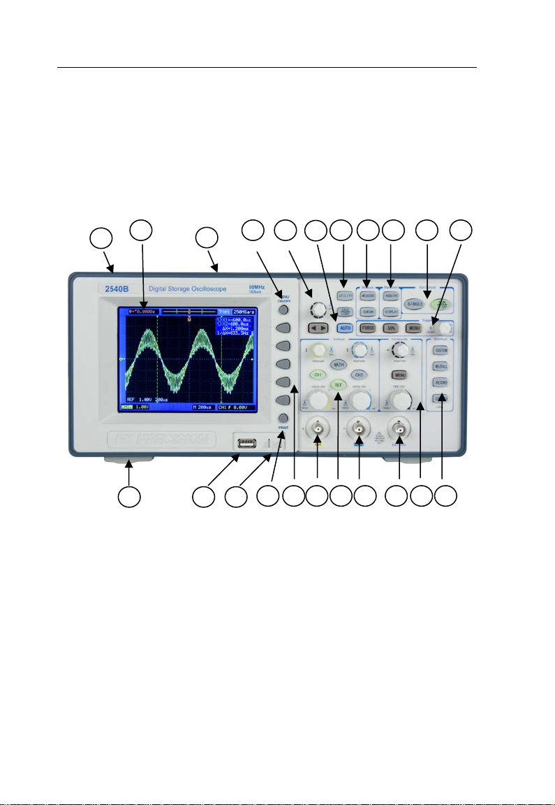
1.4 Panel and Screen Display
Front Panel Display
Figure 1 - Model 2540B
18
Page 19
Getting Started
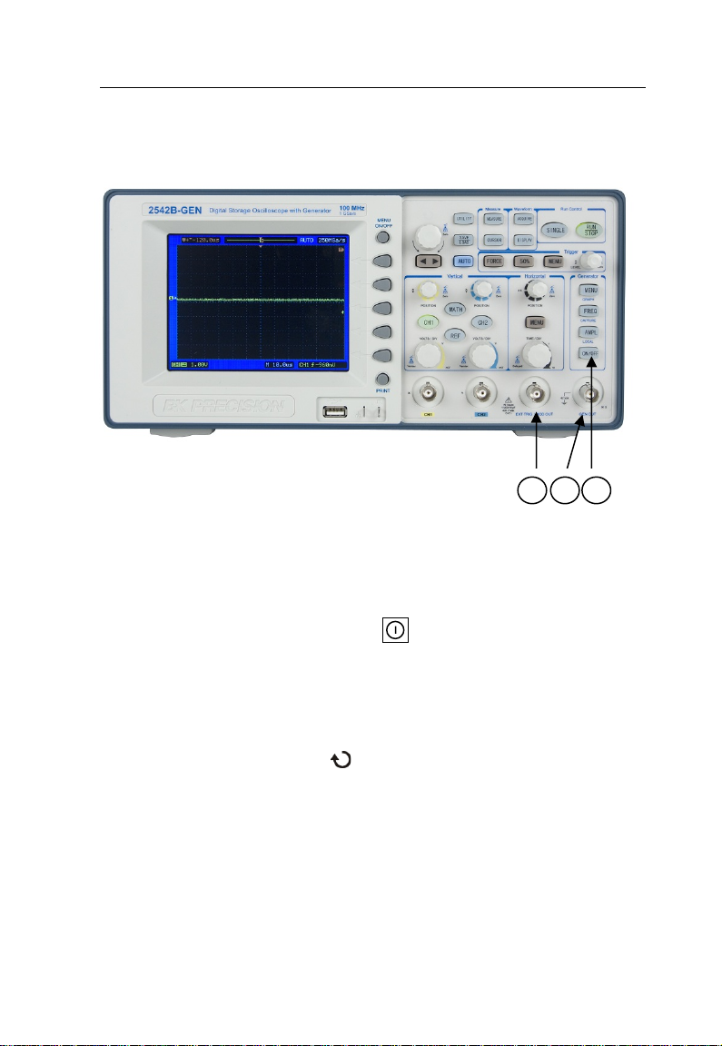
12
23
14
Figure 2 - Model 2542B-GEN
1. Power ON/OFF button (top panel)
2. LCD display screen
3. Carrying handle (top panel)
4. Menu ON/OFF button
5. Adjustment knob
6. AUTO SET button
7. UTILITY & SAVE/LOAD menu buttons
8. MEASURE & CURSOR menu buttons
9. ACQUIRE & DISPLAY menu buttons
10. RUN control ( SINGLE & RUN/STOP) buttons
19
Page 20

Getting Started
11. TRIGGER controls
12. (for models 2540B/2542B) Shortcut buttons & Local
key (Alternate function of COUNTER button; used to
set unit to local mode when in remote mode)
(for models 2540B-GEN/2542B-GEN) Function keys
to setup arbitrary waveform generator:
MENU / GRAPH button
FREQ / CAPTURE button
AMPL / LOCAL button
ON/OFF button
13. HORIZONTAL controls
14. EXT TRIG BNC terminal
(For models 2540B-GEN/2542B-GEN) EXT TRIG and
MOD OUT BNC terminal
15. Channel 2 BNC input
16. VERTICAL controls
17. Channel 1 BNC input
18. FUNCTION buttons (for soft panel menu)
19. PRINT button
20. Probe compensation terminal
21. USB host interface (supports most USB flash drives)
22. Tilt feet (bottom)
23. (For models 2540B-GEN/2542B-GEN only) GEN
OUT BNC terminal
20
Page 21
Getting Started
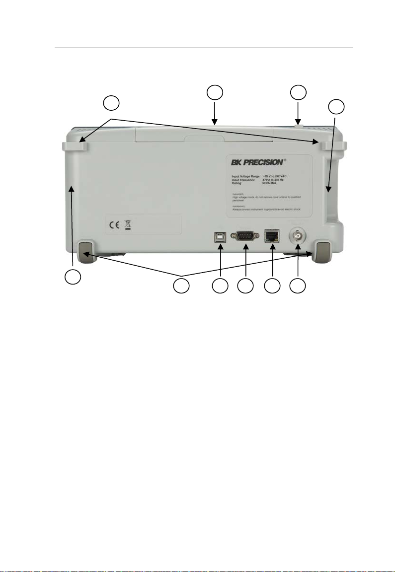
1
2 3 5 6 7 8 9
4
10
(side)
(side)
Back Panel Display
1. Security loops
2. Carrying handle
3. Power ON/OFF button
4. AC line input (side panel)
5. Pass/Fail output (isolated)
6. LAN interface port
7. RS232 serial interface port
8. USB device interface port
9. Rear rubber feet
10. Ventilation fan (side panel)
21
Page 22
Getting Started
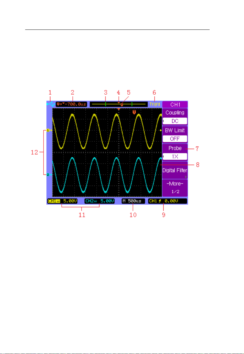
LCD Main Screen Display
The oscilloscope display contains channel acquisitions, setup
information, measurement results, and soft keys for setting
up various parameters.
1. The USB icon appears when a USB drive is inserted into
the front USB host port and ready to be used. When
instrument is in remote mode, it will display “Rmt”
indicator instead.
2. Readout showing the trigger position relative to the
horizontal center of the screen.
22
Page 23

Getting Started
3. The square brackets show the location of current display
window within the whole captured waveform. The
captured waveform color corresponds with the active
waveform color (CH1: yellow; CH2: cyan).
4. Horizontal center position icon shows the horizontal
center location within the captured waveform.
5. Trigger position icon shows the trigger location within the
record waveform.
6. Acquisition status:
AUTO – “Auto” mode.
STOP – Stop acquiring waveform data.
WAIT – Waiting to be triggered.
Trig’d – DSO has seen a trigger and is acquiring
post-trigger data.
Trig? – Looking for trigger
ROLL – When horizontal mode is set to “Roll”
7. Soft key menu which allows you to set up additional
parameters from front-panel soft keys.
8. The display area contains the waveform acquisitions,
channel identifiers, trigger and ground level indicators.
Each channel’s information appears in their respective
color.
9. Trigger readout shows trigger information such as trigger
source, trigger type as well as trigger level.
23
Page 24

Getting Started
10. Horizontal readout shows the Main or Delayed time
base.
11. Channel readouts show the scale factor, coupling,
bandwidth limit, digital filter, and invert status.
12. Waveform baseline icons show the zero-volt level of the
waveforms. The icon colors correspond to the waveform
colors.
1.5 Quick Check
Upon receiving the instrument, inspect for any noticeable
physical damages or unresponsive panel buttons. If there
are any problems, please contact B&K Precision
immediately.
Power On Check
Connect the AC Power Cord to the power input socket on the
side of the DSO. Press down the power switch button at the
top of the DSO to the ON position ( ). Verify that the
instrument turns on and the LCD screen goes into an initial
boot screen.
Press any key for the screen to load into the main screen
showing the graticule. Contact B&K Precision if the DSO
fails to load the main screen.
24
Page 25
Getting Started
Basic Check
Please follow the steps below when checking the
oscilloscope’s functionality.
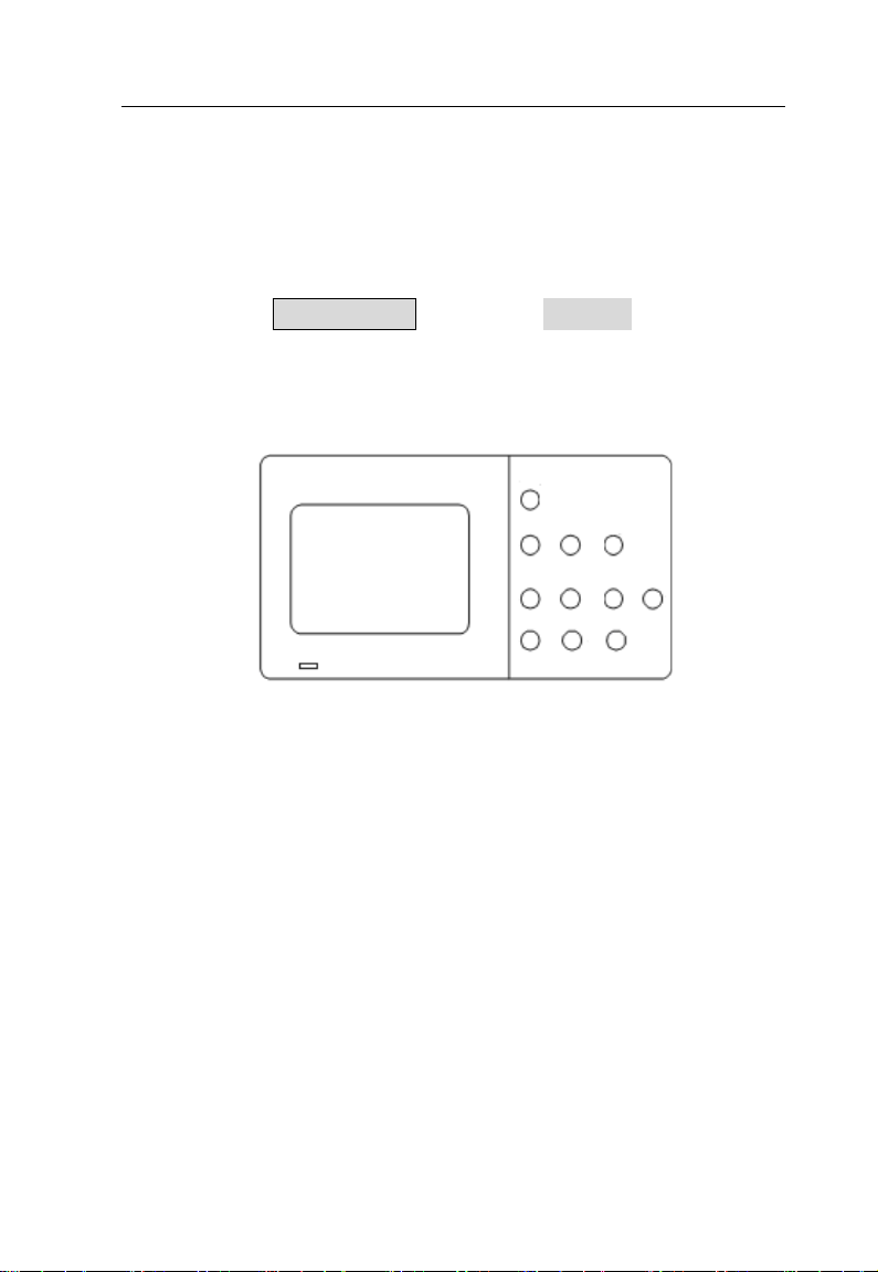
1. Power on the oscilloscope.
Press SAVE/LOAD and Select Factory to set DSO to
factory settings. The probe default attenuation is 1X.
2. Set the switch to 1X on the probe and connect the
probe to channel 1 on the oscilloscope. To do this,
align the slot in the probe connector with the key on
the CH 1 BNC, push to connect, and twist to the right
to lock the probe in place. Connect the probe tip and
reference lead to the probe compensation terminal.
25
Page 26
Getting Started
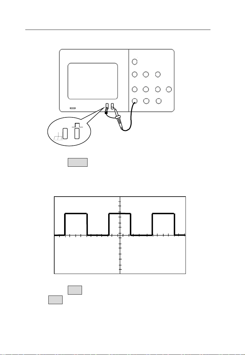
3. Press AUTO to show the 1 kHz frequency square
wave in a few seconds.
4. Press CH1 two times to cancel the channel 1, Press
CH2 to c hange screen into channel 2, reset the
channel 2 and repeat step 2 and step 3 for CH2.
26
Page 27
Getting Started
1.6 Probe Safety
A guard around the probe body provides a finger barrier for
protection from electric shock.
Connect the probe to the oscilloscope and connect the
ground terminal to ground before you take any
measurements.
Note: To avoid electric shock when using the probe,
keep fingers behind the guard on the probe body.
Note: To avoid electric shock while using the probe, do
not touch metallic portions of the probe head
while it is connected to a voltage source. Connect
the probe to the oscilloscope and connect the
ground terminal to ground before you take any
measurements.
27
Page 28

Getting Started
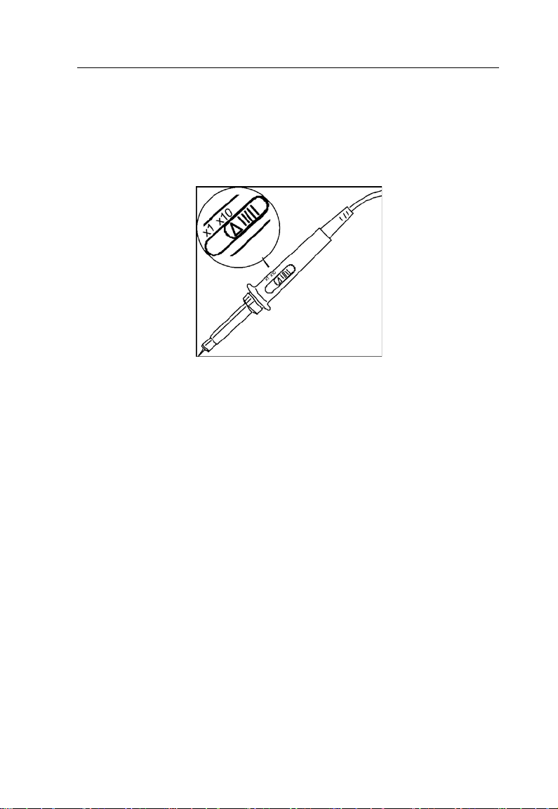
1.7 Probe Attenuation
Probes are available with various attenuation factors which
affect the vertical scale of the signal.
You can push a vertical menu button (such as the CH 1
button), and select the Probe option that matches the
attenuation factor of your probe.
Note: The default setting for the Probe option is 1X.
Be sure that the attenuation switch on the probe matches the
Probe option in the oscilloscope. The included probes can
switch between 1X and 10X.
Note: When the attenuation switch is set to 1X, the
probe limits the bandwidth of the oscilloscope to
10 MHz (according to Probe spec). To use the full
bandwidth of the oscilloscope, be sure to set the
switch to 10X.
1.8 Probe Compensation
Perform this adjustment to match your probe to the input
channel. This should be done whenever you attach a passive
28
Page 29
Getting Started
probe for the first time to any input channel. A poorly
compensated probe can introduce measurement errors.
1. Set both the probe and the oscilloscope attenuation
factor to X10 respectively.
2. Connect the oscilloscope probe to channel 1. Attach the
probe tip and reference lead to the probe compensation
terminal and to the chassis ground terminal, then press
AUTO key.
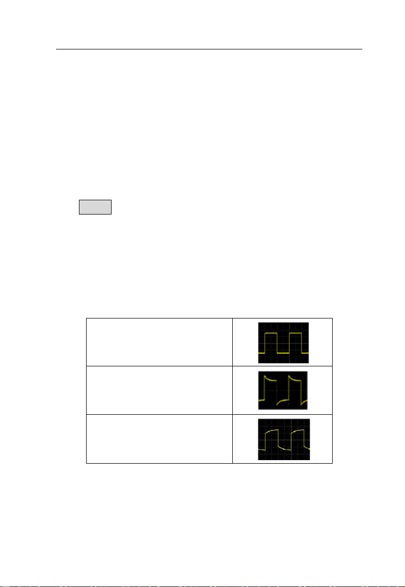
3. Use a nonmetallic tool to adjust the trimmer capaci to r on
the probe for the flattest pulse possible (see “Correct
compensation” image below). The trimmer capacitor is
located either on the probe BNC connector or above the
probe attenuation switch.
Correct compensation
Over compensated
Under compensated
4. Connect probes to channel 2. Repeat the above steps.
This matches each probe to each channel.
29
Page 30

Page 31

Basic Operation
2 BASIC OPERATION
• Using Quick Help
• Using Autoset
• Vertical Controls
• Horizontal Controls
• Trigger Controls
• RUN Controls
31
Page 32
Basic Operation
2.1 Using Quick Help
The digital storage oscilloscope has a quick help system that
provides a description of functionality for each front panel
keys and soft panel keys.
Press and hold down the key or the softkey that you want to
see help description for. The help information will display and
remain at the center of the screen as shown below until
another key is pressed or a knob is turned.
Note: Quick help is not available for CUSTOM shortcut
key. Refer to “CUSTOM Button” section for
details on its usage.
32
Page 33

Basic Operation
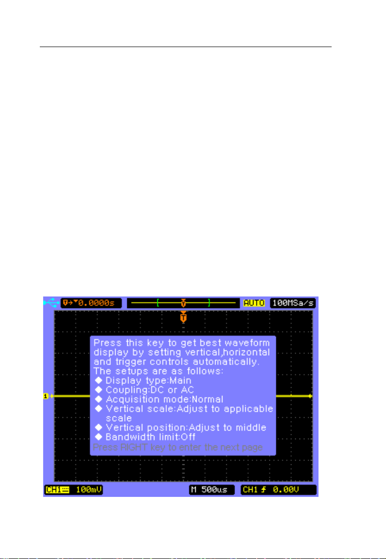
If there are more than one page of help information, press the
key to browse the previous or next pages.
2.2 Using Autoset
The 2540B/2542B/2540B-GEN/2542B-GEN oscilloscopes
provide an Autoset function which sets the vertical, horizontal,
and trigger controls automatically for optimal display of the
signal(s) connected at either or both CH1 and CH2.
Autoset function detects, turns on, and scales any channel
with a repetitive waveform if it meets the following
requirements:
• Frequency of at least 50Hz
• Duty cycle greater than 0.5%
• Amplitude of at least 10 mVpp
Note: Any channels that do not meet these requirements
are turned off.
When you are using more than one channel, the Autoset
function sets the vertical controls for each channel and uses
CH1 to set the horizontal and trigger controls.
To configure the oscilloscope quickly and automatically to
see connected signals, press the AUTO key. The
oscilloscope will take a few seconds to automatically set
33
Page 34

Basic Operation
various parameters. If signal is found, it will beep once and
open the AUTO menu before displaying the signal. If there
are no signals, no beep will occur and a display message will
read “No signal is found”.
To configure the oscilloscope to display multiple cycles, press
Multi-Cycle softkey in the AUTO menu.
To configure the oscilloscope to display a single cycle, press
Single Cycle softkey in the AUTO menu.
To undo the effects of Autoset, press the Undo Autoset
softkey in the AUTO menu before pressing any other key.
This is useful when you have unintentionally pressed the
AUTO key or do not like the settings Autoset has selected
and want to return to your previous settings.
34
Page 35

Basic Operation
Note: Auto set function can be disabled. See
“Appendix B: Disabling Auto Function” for details
2.3 Vertical Controls
Vertical controls
Vertical Position Knob (CH1, CH2)
Turn the small vertical position knob above the channel key
to move the channel’s waveform and its g r ound level icon ( )
up or down on the display. The voltage value momentarily
displayed (shown below) in the bottom left corner of the
display represents the voltage difference between the vertical
center of the display and the ground level ( ).
35
Page 36

Basic Operation
Press the vertical position knob to bring the channel’s
waveform and its ground level icon ( ) directly back to t he
vertical center of the display.
Vertical Scale Control (CH1, CH2)
Turn the large vertical scale k nob below the channel key to
set the scale factor for the channel. The vert ical scale knob
changes the channel scale in a 1-2-5 step sequence. The
channel scale factor value is displayed in the bottom left
portion of the display.
Press the vertical scale knob to toggle between Fine and
Coarse control. When fine is selected, you can change the
channel’s vertical sensitivity in smaller resolution. When
36
Page 37

Basic Operation
coarse is selected, the vertical scale knob changes the
channel scale in a 1-2-5 step sequence.
Channel Keys CH1, CH2
Press the channel key from the front panel to display the
channel’s menu and turn the display of the channel on or off.
The channel is displayed when the key is illuminated.
The channel menu of a channel must be displayed first
before you can turn off the channel. For example, suppose
CH1 and CH2 are both displayed and the CH2 menu is also
displayed. In order to turn CH1 off, you should press the CH1
key fir st to show CH1 menu on the display, then press CH1
key again to turn off CH1.
CH1, CH2 Menu
Press the channel key CH2 to display the channel’s menu
and turn on the channel display.
Channel Coupling
Press the channel key CH2, then press the Coupling softkey
to select AC coupling mode.
AC coupling places a high pass filter in series with the input
signal that blocks the DC component of the input signal. AC
coupling is useful for viewing waveforms with large DC
offsets.
37
Page 38

Basic Operation
AC Coupling
Press the channel key CH2, then press the Coupling softkey
again to select DC coupling mode.
DC coupling passes both AC and DC components of the
input signal. DC coupling is useful for viewing low frequency
waveforms that do not have large DC offsets.
DC Coupling
38
Page 39
Basic Operation
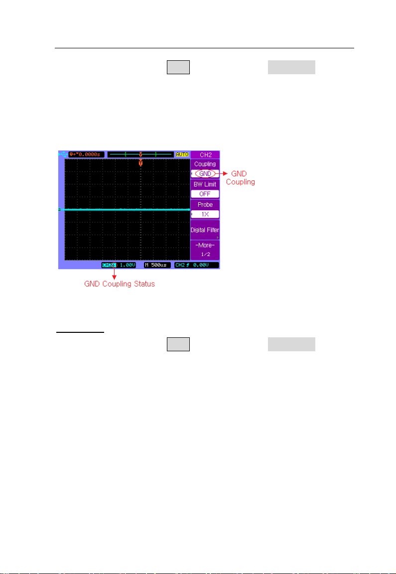
Press the channel key CH2, then press the Coupling softkey
until GND coupling is selected.
GND mode blocks both AC and DC components of the input
signal and connect the input to the ground level.
GND Coupling
BW Limit
Press the channel key CH2, then press the BW Limit softkey
to turn the bandwidth limit on or off for the selected channel 2.
When it is off, it passes both the high and low frequency
components.
39
Page 40

Basic Operation
BW Limit off
When it is on, the maximum bandwidth for the channel is
approximately 20 MHz. For waveforms with frequencies
below this, turning bandwidth limit on removes unwanted high
frequency noise from the waveform.
BW Limit on
40
Page 41

Basic Operation
Probe Attenuation Setting
Probes are available with various attenuation factors which
affect the vertical scale of the signal. You can manually select
the factor that matches the attenuation of your probe.
For example, to match a probe set to 10X connected to CH2,
press the channel key CH2, and then press the Probe
softkey and select 10X.
Press the Probe softkey again and select 1X when a probe
with 1:1 attenuation factor is connected to CH2.
Set Probe Attenuation Factor to 1X
41
Page 42

Basic Operation
Digital Filter
Each channel has built-in digital filters that can be applied to
the connected signal.
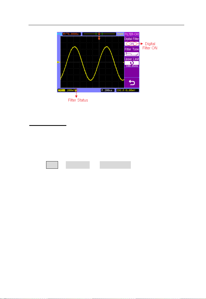
Press the channel key CH1, then press the Digital Filter
softkey to display the FILTER-CH1 menu. Four kinds of f ilter
types are available:
1. Low pass filter
2. High pass filter
3. B and pass filter
4. B and block filter
Press the Upper Limit or Lower Limit softkey and then
adjust the Entry knob to set the high and/or low
frequency range for the filter.
Digital Filter is off
42
Page 43
Basic Operation
Digital Filter is on
Vertical Scale
Turn the large vertical scale knob below the channel key to
set the scale factor for the channel. The channel scale factor
value is displayed in the bottom left portion of the display.
Press CH2→ More 1/2 → Volts Scale to select Coarse or
Fine adjustment. You can also press the large vertical scale
knob to toggle between Fine and Coarse. When Coarse is
selected, the vertical scale knob changes the channel scale
in a 1-2-5 step sequence. When Fine is selected, the vertical
scale knob changes the channel scale in a smaller resolution.
43
Page 44

Basic Operation
Fine Vertical Scale
Vertical Invert
Press CH2→ More 1/2 → Invert to set Invert on or off. When
Invert is turned on, the voltage values of the displayed
waveform are inverted. Invert affects how a channel is
displayed, but does not affect triggering. If the oscilloscope is
set to trigger on a rising edge, it remains set to trigger on the
same edge after the channel is inverted.
Inverting a channel will also change the result of any math
function selected in the MATH menu or any measurement.
44
Page 45

Basic Operation
Vertical Invert off
Vertical Invert on
45
Page 46

Basic Operation
MATH Functions
Dual Waveform Calculation
Press MATH channel key to turn on the MATH menu, p age
½.
Softkey Options Description
A+B Add A and B
Operate
Source A
Source B
Invert
More 1/2
A-B Subtract B from A
A X B Multiply A by B
FFT Access FFT menu
CH1 Select CH1 as Source A
CH2 Select CH2 as Source A
CH1 Select CH1 as Source B
CH2 Select CH2 as Source B
ON Math invert ON
OFF Math invert OFF
---- Select page 2/2
46
Page 47

Basic Operation
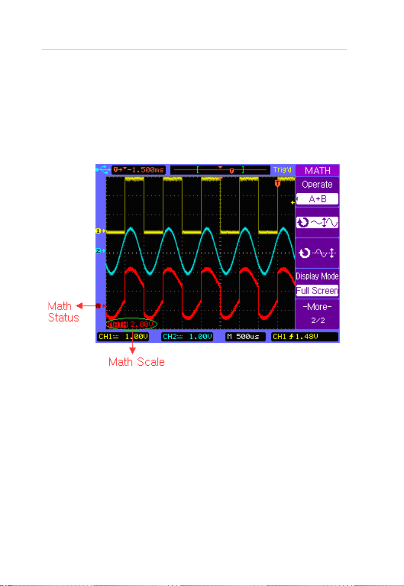
Display Math waveform
Press softkey More 1/2 to display MATH menu page 2/2.
Softkey Options Description
A+B Add A and B
Operate
Display
Mode
More 2/2
A-B Subtract B from A
A X B Multip ly A by B
FFT Access FFT menu
Split
Screen
Full
Screen
---- Select page 1/2
Vertical scale control
Vertical position control
Split the display into Main
and Math sections
in full screen
47
Page 48
Basic Operation
Example:
Select the A+B math function, then select CH1 as the Source
A, and select CH2 as the Source B. The resulting math
waveform will look like below:
Math A+B
48
Page 49

Basic Operation
FFT Spectrum Analysis
You can use the FFT function to measure harmonic
components and distortion in systems, to characterize noise
in DC power supplies, and to analyze vibration.
Press MATH channel key to turn on the MATH menu page
1/2, and then press Operate softkey to select FFT. The FFT
menu page 1/2 will be displayed.
Softkey Options Description
A+B Add A and B
Operate
A-B Subtract B from A
A X B Multiply A by B
FFT Access FFT menu
CH1 Select CH1 for FFT
Source
CH2 Select CH2 for FFT
Rectangular Use Rectangular window
Window
Scale
More 1/2
Hanning Use Hanning window
Hamming Use Hamming window
Blackman Use Blackman window
Flattop Use Flattop window
Vertical scale in dBV
dBV RMS
RMS
V RMS Vertical scale in V RMS
---- Select page 2/2
49
Page 50

Basic Operation
Softkey
Options
Description
More 2/2
Press softkey More 1/2 to display FFT menu page 2/2.
A+B Add A and B
Operate
A-B Subtract B from A
A X B Multip l y A by B
FFT Access FFT menu
Split
Display
Mode
Screen
Full
Screen
---- Select page 1/2
Vertical scale control
Vertical position control
Split the display into Main
and Math sections
Display Math waveform in
full screen
50
Page 51

Basic Operation
Example:
Select CH1 as the Source for FFT, select Rectangular
Window, set Scale to dBV RMS, and then the FFT waveform
will look like below. You can also measure the amplitude and
frequency of the corresponding point with the manual cursors
(See “
CURSOR Menu”).
FFT Spectrum Analysis
51
Page 52

Basic Operation
REF Function
The REF function allows users to store and recall a waveform
as a reference. This is useful for comparing and analyzing
signals from different systems.
Press REF channel key to turn on the REF menu, page 1/2.
Softkey Options Description
Source
CH1 Save CH1 as reference
CH2 Save CH2 as reference
Volts
Scale
Coarse Coarse vertical scaling
Fine Fine vertical scaling
More
1/2
---- Select page 2/2
REF vertical scale control
REF vertical position control
52
Page 53

Basic Operation
2/2
Press softkey More 1/2 to display REF menu, page 2/ 2.
Softkey Options Description
Invert
ON REF invert ON
OFF REF invert OFF
Internal
Storage
External
Storage
INTERNAL
menu
EXTERNAL
menu
Save the reference
waveform to the
internal memory
Save the reference
waveform to the
USB mass storage
device
More
---- Select page 1/2
Press REF channel key to turn on the REF m enu page 1/2,
press softkey More 1/2 to display REF menu page 2/2. Load
the latest saved reference waveform from the internal
memory by selecting Internal Storage or locate and load
reference waveform file from the external memory by
selecting External Storage.
You can use the horizontal position and scale control knob to
change the time base of the reference waveform.
53
Page 54

Basic Operation
Press or softkey and turn the Entry knob
to change the vertical scale or position of the reference
waveform.
Press REF→ Internal Storage → Save to save the
waveform of the Source channel as the reference waveform
to the internal memory.
Save a Reference waveform
Note: The reference waveform function is unavailable
when X-Y mode is selected.
54
Page 55
Basic Operation
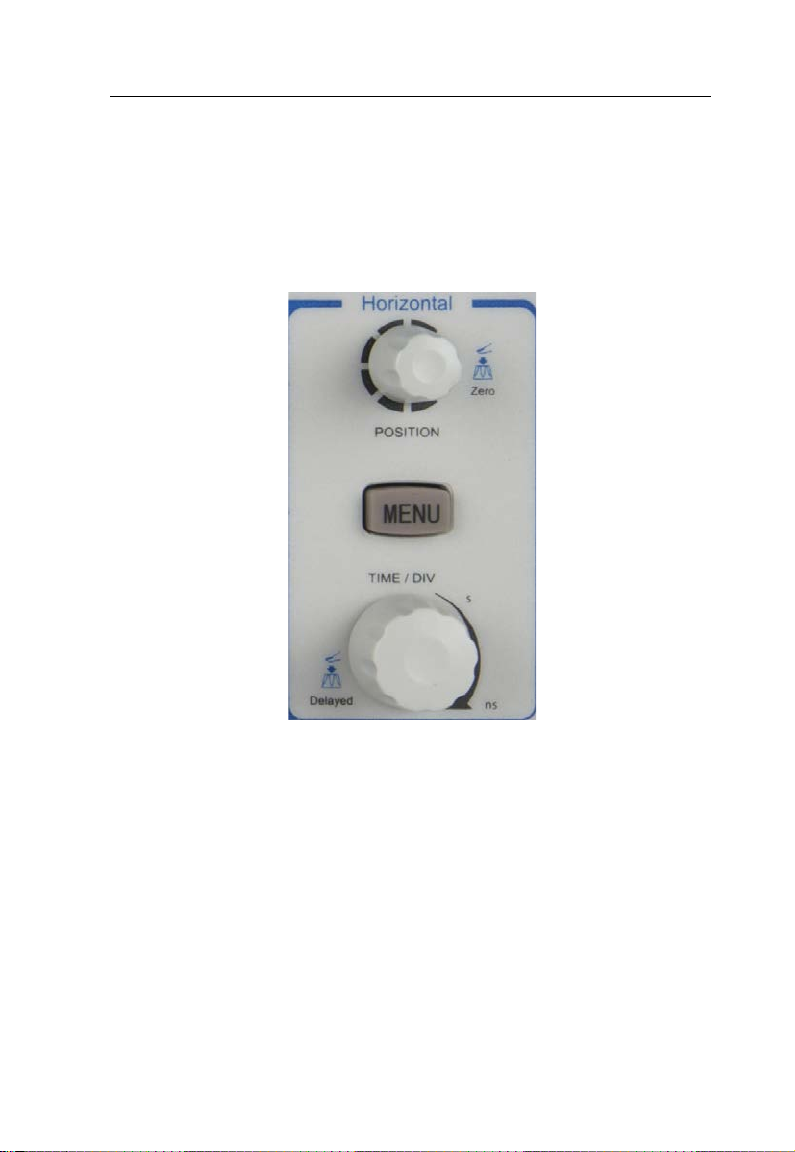
2.4 Horizontal Controls
Use the horizontal controls to adjust the time base, adjust the
trigger location, and to examine waveform details more
closely.
Horizontal Controls
55
Page 56

Basic Operation
Horizontal Position Control
When the oscilloscope is running, this control lets you set the
acquisition window relative to the trigger point. When the
oscilloscope is stopped, you can turn this knob to pan
through the data horizontally. This lets you see the captured
waveform before the trigger or after the trigger.
The trigger position is marked with the indicator “ ” at the top
of the graticule and also in the waveform record data icon at
the top of the screen.
The small inverted triangle () is the time reference indicator.
When you change the horizontal scale, the waveforms
contract or expand about this point.
Press the horizontal position control knob key to set the time
delay to zero, and the trigger position indicator ( ) will move
right below the time reference indicator().
Note: The horizontal position control is unavailable
when X-Y horizontal mode is selected.
Horizontal Scale Control
Use the horizontal scale control to adjust the time base. The
scale expands or contracts around the center of the screen.
The horizontal scale factor can be set in a 1-2-5 sequence.
56
Page 57

Basic Operation
Softkey
Options
Description
1/2
Press the horizontal scale control knob to toggle between
Main and Delayed horizontal display mode.
Horizontal MENU key
Press the horizontal MENU k ey to display the HORIZONTAL
menu. This menu lets you select t he horizontal mode: Main,
Delayed, Roll, or X-Y.
Press the horizontal MENU k ey to display the HORIZONTAL
menu page 1/2.
Main
Delayed
X-Y
Roll
-More-
√ Main mode is ON
---- Main mode is OFF
√ Delayed mode is ON
---- Delayed mode is OFF
√ X-Y mode is ON
---- X-Y mode is OFF
√ Roll mode is ON
---- Roll mode is OFF
---- Select page 2/2
57
Page 58
Basic Operation
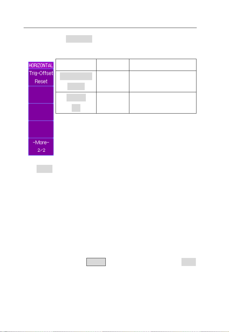
Reset the delay time
Press softkey More 1/2 to display the HORIZONTAL menu
page 2/2.
Softkey
Trig-Offset
Reset
-More2/2
Options Description
---to zero
---- Select page 1/2
Main - Horizontal Mode
Main horizontal mode is the normal viewing mode for the
oscilloscope. When the oscilloscope is stopped, you can use
the horizontal controls to pan and zoom the waveform. When
the oscilloscope is running in Main mode, use the horizontal
scale knob to change horizontal scale factor and use the
horizontal position knob to set the delay time. The time
base (second/division) value is displayed at the bo ttom of the
screen.
Press the horizontal MENU key and then press the Main
softkey to select the main horizontal mode.
58
Page 59
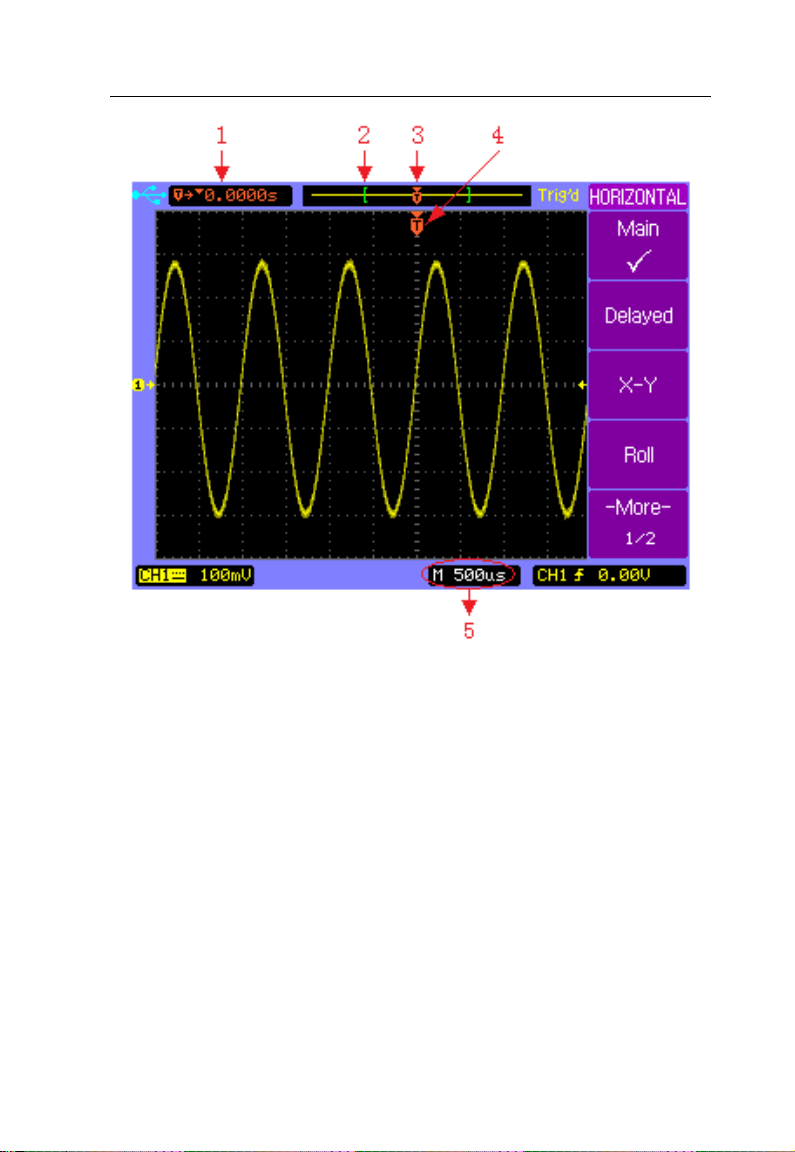
Basic Operation
Main Horizontal Mode
1. Readout shows the delay time or the trigger location
within the record data relative to the time reference point
().
2. The square brackets show the location of current display
window within the record data.
3. Trigger position within the record data.
4. Trigger position on the current waveform display window.
5. Main time base.
59
Page 60

Basic Operation
Delayed - Horizontal Mode
Delayed horizontal mode is an expanded version of main
mode. When Delayed mode is selected, the display divides i n
half. The top half of the display shows the normal waveform
and bottom half displays the delayed waveform.
Delayed waveform is a magnified portion of the normal
waveform. You can use delayed waveform to locate and
horizontally expand part of the normal waveform for a more
detailed analysis of signals.
The area of the normal display that is expanded is marked on
each end with a vertical shaded area. The unshaded area
shows what portion of the normal waveform is expanded in
the lower half.
To change the time base for the delayed window, turn the
horizontal scale knob. As you turn the knob, the time base for
the delayed window is displayed just above the main time
base.
To change the time base for the normal window, press the
Main softkey, then turn the horizontal scale control knob.
Connect a triangle signal source to CH1, press the horizontal
MENU k ey and then press the Delayed softkey to enter the
Delayed mode. You can also press the horizontal scale
60
Page 61

Basic Operation
control knob key to toggle between Main and Delayed mode
directly.
Delayed Horizontal Mode
61
Page 62
Basic Operation
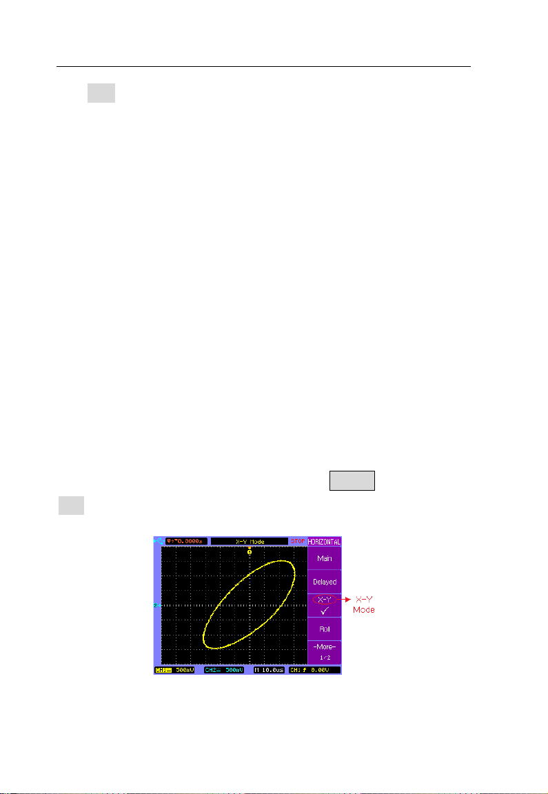
X-Y Horizontal Mode
X-Y mode changes the display from a volts-versus-time
display to a volts-versus-volts display. The time base is
turned off. CH1 amplitude is plotted on the X axis and CH2
amplitude is plotted on the Y axis.
You can use X-Y mode to compare frequency and phase
relationships between two signals. X-Y mode can also be
used with transducers to display strain versus displacement,
flow versus pressure, voltage versus current, or voltage
versus frequency.
In order to get a better view of the waveform, proper vertical
scale should be selected before selecting the X-Y mode.
Use X-Y mode to compare two signals with the same
frequency and different phase. Connect the two si gnal to CH 1
and CH2 respectively. Press horizontal MENU key and then
X-Y softkey to select X-Y mode.
X-Y Horizontal Mode
62
Page 63

Basic Operation
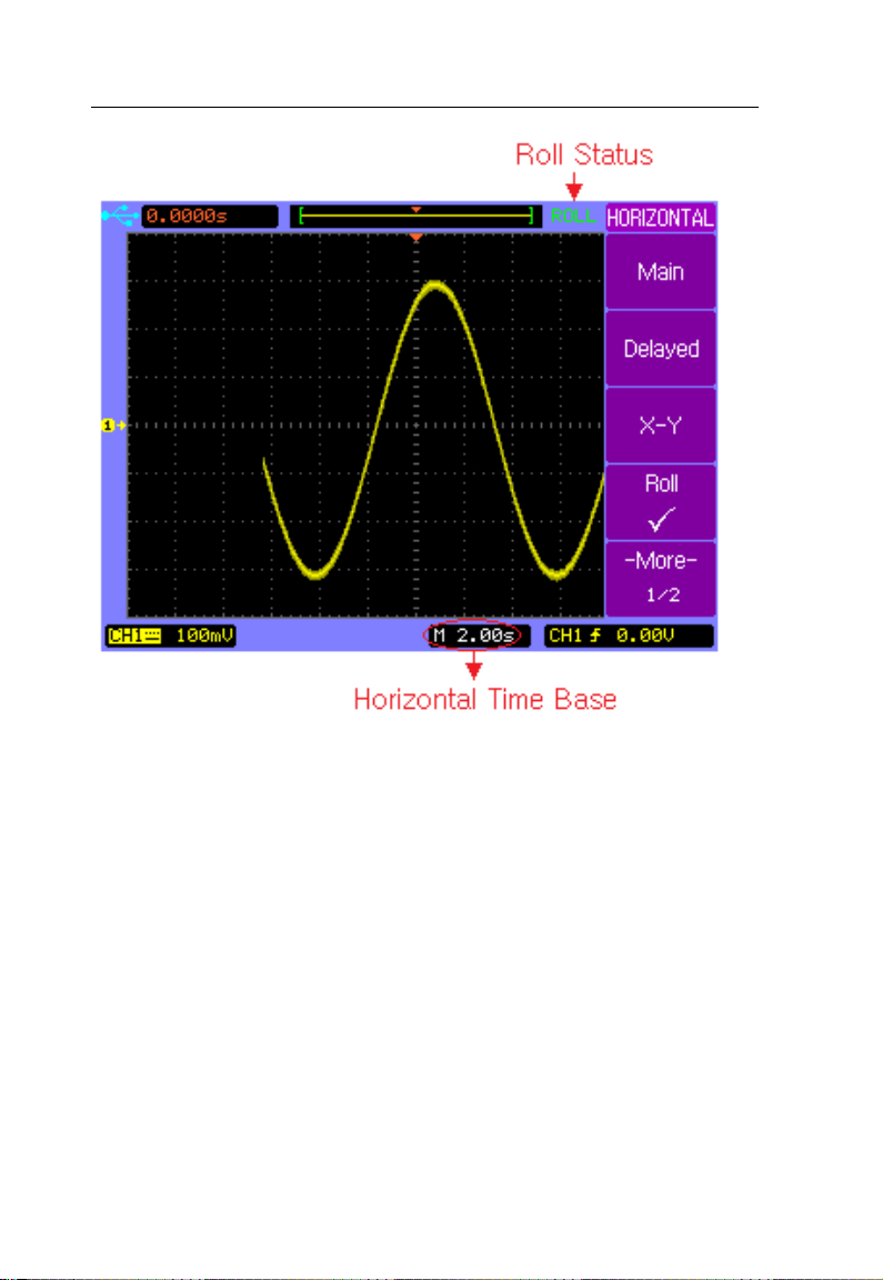
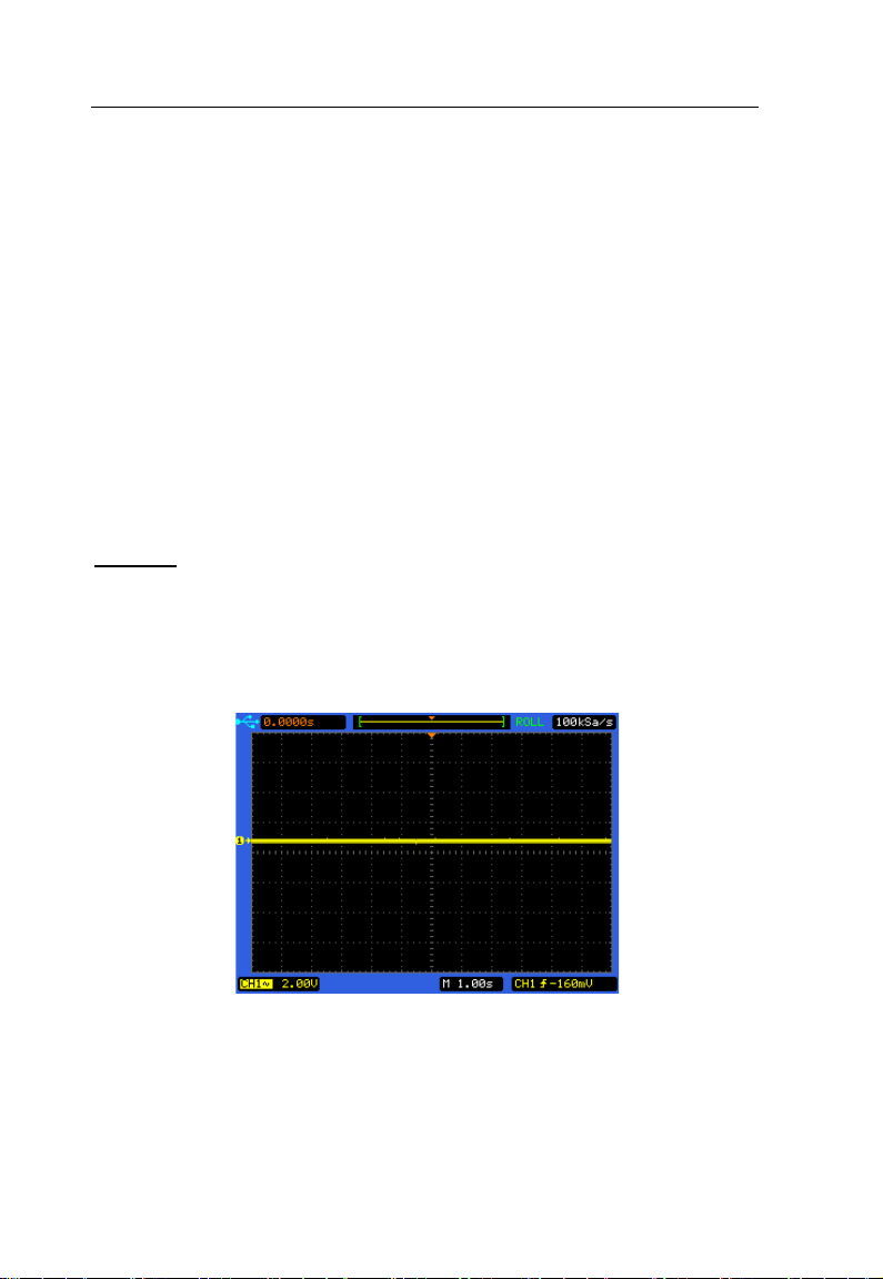
Roll - Horizontal Mode
Roll mode causes the waveform to move slowly across the
screen from right to left.
Note: It only operates on time base settings of 500
ms/div or slower. If the current time base setting
is faster than the 500 ms/div limit, it will be set to
500 ms/div when Roll mode is selected.
In Roll mode there is no trigger. The fixed reference point on
the scr een is the right edge of the scr een and refers to t he
current moment in time. Events that have occurred are
scrolled to the left of the reference point. Since there is no
trigger, no pre-trigger information is available.
If you would like to pause the display after a full screen of
acquisition in Roll mode, pres s t he SINGLE key. To clear the
display and restart another full screen acquisition in Roll
mode, press the SINGLE key again.
Press the horizontal MENU key and then press the Roll
softkey to select the Roll mode. The waveform will move
slowly across the screen from right to left.
The fastest time base is 500 ms in roll mode.
63
Page 64
Basic Operation
Roll Horizontal Mode
64
Page 65

Basic Operation
2.5 Trigger Controls
The trigger controls determine when the oscilloscope starts to
acquire and display the waveform. When a trigger is found,
the oscilloscope will acquire sufficent data to display the
waveform.
Note: Trigger controls are functional when the
oscilloscope works under Main or Delayed
horizontal mode.
Trigger Controls
65
Page 66
Basic Operation
Trigger Control MENU key
Press the trigger control MENU key to show the TRIGGER
menu and then press the Type softkey to select Edge, Pulse
or Video.
Set to 50% key
Press the 50% key to set the trigger level to the 50%
amplitude level of the trigger source waveform.
Force Trigger key
Press the FORCE key to force an immediate trigger event,
even in the absence of a signal. This function is useful in
following situations :
If you do not see a waveform on the screen when using
Normal trigger mode, press the FORCE key to acquire the
signal baseline to verify that it is on the screen.
After you press the SINGLE k ey to set up for a single shot
acquisition, you can press the FORCE key to test and verify
the control settings.
Trigger Level Control
Use the trigger level control knob to adjust the trigger level.
When you change the trigger level, a horizontal red line
temporarily appears to show you the level position on screen.
66
Page 67

Basic Operation
After the line disappears, the trigger level is marked with a
small left arrow.
Auto and Normal Trigger Modes
Press the trigger MENU key to display the TRIGGER menu
and press the Mode softkey to select Auto or Normal trigger
mode.
Auto mode
Use the auto trigger mode for signals other than
low-repetitive-rate signals and for unknown signal levels. To
display a DC signal, you must use Auto trig ger mode since
there is no edge to trigger on.
When you press RUN/STOP key to start acquiring, the
oscilloscope first fill the pre-trigger buffer. It starts to search
for a trigger after the pre-trigger buffer is filled, and continues
to flow data through this buffer whi le it searches for the tri gger.
While searching for the trigger, the oscilloscope overflows the
pre-trigger buffer; the first data put into the buffer is the first
pushed out. When a trigger is found, the pre-trigger buffer will
contain the events that occurred just before the trigger. If no
trigger is found, the oscilloscope generates a trigger and
displays the data as though a trigger had occurred. In this
case, the background of the Auto indicator at the top of the
67
Page 68

Basic Operation
display will flash, indicating that the oscilloscope is force
triggered.
When you press the SINGLE key, the oscilloscope will fill the
pre-trigger buffer, and continue to flow data through the
pre-trigger buffer until the Auto trigger overrides the search
and forces a trigger. At the end of the trace, the oscilloscope
will stop and display the results.
Normal mode
Use Normal trigger mode for low repetitive-rate signals or
when Auto trigger is not required.
In Normal mode the oscilloscope must fill the pre-trigger
buffer with data before it will begin searching for a trigger
event. While searching for the trigger, the oscilloscope
overflows the pre-trigger buffer; the first data put into the
buffer is the first pushed out.
When the trigger event is found, the oscilloscope will fill the
post-trigger buffer and display the results. If the acquisition
was initiated by RUN/STOP, the process repeats. If the
acquisition was initiated by SINGLE, then the acquisition
stops.
In either Auto or Normal mode, the trigger may be missed if
the oscilloscope’s pre -tr igger buffer is not full yet.
68
Page 69

Basic Operation
Holdoff Function
Holdoff sets the amount of time that the oscilloscope will wait
before re-initializing the trigger circuit. You can use the
holdoff function to stabilize the display of complex waveforms.
With the holdoff function, you can synchronize triggers. The
oscilloscope will trigger on one edge of the waveform, and
ignore further edges until the holdoff time is up. The
oscilloscope will then re-initialize the trigger circuit to wait for
the next edge trigger. This allows the oscilloscope to trigger
on a repeating pattern in a waveform.
Turn the Entry knob to increase or decrease the trigger
hold off time shown in the Holdoff softkey. To get a stable
trigger on the pulse burst shown on the screen, set the
holdoff time to be slightly less than the period of the pulse
burst.
Holdoff Function
69
Page 70

Basic Operation
Video
Video triggering
Edge
Edge triggering
Pulse
Pulse width triggering
CH1
Trigger on CH1
CH2
Trigger on CH2
AC Line
Trigger on AC line signal
gger even without a
valid event
Trigger only on a valid
event
Trigger
Setup
Select trigger SETUP
menu.
Edge Trigger
Use the Edge triggering to trigger on the rising or falling edge
of the input signal at the trigger threshold.
Press trigger control MENU key to display the TRIGGER
menu, then press Type softke y to select E dge trigger.
Softkey Options Description
Type
EXT Trigger on EXT
Source
EXT/5 Trigger on EXT/5
Slope
Mode
Alternating
Auto
Normal
----
70
Trigger on CH1 and
CH2 alternately
Rising edge of a signal
Falling edge of a signal
Tri
Page 71

Basic Operation
Note: (For models 2540B-GEN and 2542B-GEN only)
When Source is set to EXT or EXT/5, the EXT
TRG/MOD OUT BNC terminal will function as an
external trigger terminal. When Source i s set to
all other options, the same terminal will function
as the modulation waveform output that is par t of
the built-in arbitrary waveform generator.
Pulse Width Trigger
Pulse width triggering sets the oscilloscope to trigger on a
positive or negative pulse of a specified width from 20 ns to
10 s.
Press trigger control MENU key to display the TRIGGER
menu page 1/2, then press Type softkey to select Pulse
trigger.
Softkey Options Description
Video Video triggering
Type
Edge Edge triggering
Pulse Pulse width triggering
CH1 Trigger on C H1
CH2 Trigger on C H2
EXT Trigger on EXT
Source
EXT/5 Trigger on EXT/5
Alternating
CH1 and CH2
alternately
71
Page 72

Basic Operation
Setup
Positive greater than
Positive equal
Positive within
Pulse
Mode
Positive less than
Negative greater than
Negative equal
Negative within
Negative less than
Pulse
Set the pulse width
More 1/2
---- Select page 2/2
Note: (For models 2540B-GEN and 2542B-GEN only)
When Source is set to EXT or EXT/5, the EXT
TRG/MOD OUT BNC terminal will function as an
external trigger terminal. When Source i s set to
all other options, the same terminal will function
as the modulation waveform output that is part of
the built-in arbitrary waveform generator.
Press trigger control MENU key to display the TRIGGER
menu, press Type softkey to select Pulse trigger and then
press the More 1/2 softkey to display TRIGGER menu p age
2/2.
72
Page 73

Basic Operation
en without a
Trigger only on a valid
Select trigger SETUP
Softkey Options Description
Video Video tr igger ing
Type
Edge Edge triggering
Pulse Pulse width triggering
Auto
Mode
Normal
Trigger
Setup
More
2/2
Trigger ev
valid event
event
---menu
---- Select page 1/2
73
Page 74

Basic Operation
Trigger on CH1 and
More 1/2
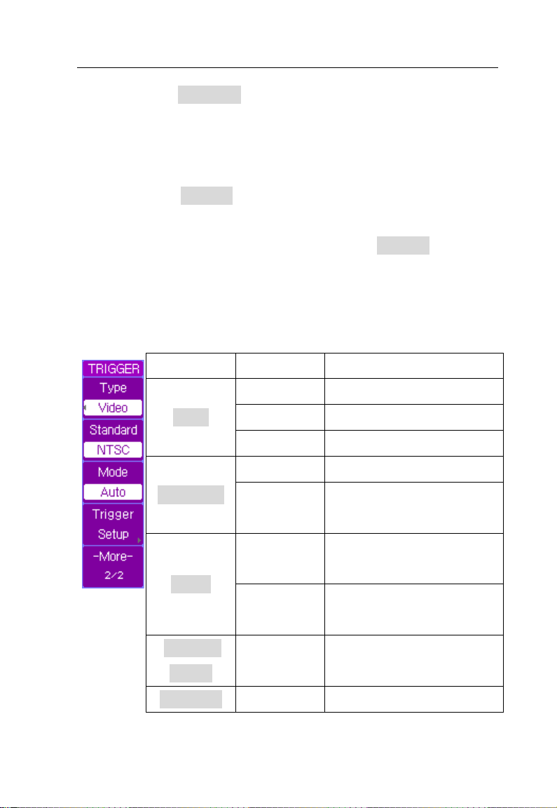
Video Trigger
Choose video triggering to trigger on the odd fields, even
fields, or on all the lines of a NTSC or PAL/SECAM video
signal.
Press trigger control MENU key to display the TRIGGER
menu, then press Type softkey to select Video trigger.
Softkey Options Description
Video Video triggering
Type
Source
Polarity
Sync
Edge Edge triggering
Pulse Pulse width triggering
CH1 Trigger on CH1
CH2 Trigger on CH2
EXT Trigger on EXT
EXT/5 Trigger on EXT/5
Alternating
Odd Field Trigger on odd fields
Even Field Trigger on even fields
All Lines Trigger on all lines
Line # Trigger on specific line
---- Select page 2/2
CH2 alternately
Positive polarity
Negative polarity
74
Page 75
Basic Operation
PAL/SECAM
Trigger on PAL or
Trigger only on a valid
Trigger even without a
Select trigger SETUP
More 2/2
Press softkey Mo re 1/2 to display the TRIGGER menu page
2/2.
Note: (For models 2540B-GEN and 2542B-GEN only)
When Source is set to EXT or EXT/5, the EXT
TRG/MOD OUT BNC terminal will function as an
external trigger terminal. When Source i s set to
all other options, the same terminal will function
as the modulation waveform output that is part of
the built-in arbitrary waveform generator.
Softkey Options Description
Video Video t r iggering
Standard
Type
Mode
Trigger
Setup
Edge Edge triggering
Pulse Pulse width triggering
NTSC Trigger on NTSC signal
SECAM signal
Normal
event
Auto
valid event
---menu
---- Select page 1/2
75
Page 76

Basic Operation
Softkey
Options
Description
by turning the entry
Set up the holdoff time
Reset
eturn to the TRIGGER
Press softkey Trigger Setup from the TRIGGER menu page
2/2 to display the trigger SETUP menu.
Set the trigger sensitivity
Sensitivity
knob
AC AC coupling
DC
DC coupling
Coupling
LF Reject Reject low frequencies
Holdoff
HF Reject
Reject high frequencies
between two consecutive
triggers
Holdoff
Reset the holdoff ti me to
---default value 100 ns
R
---menu
Note: There will be no coupling menu item when video
trigger mode is selected in the trigger SETUP
menu.
76
Page 77

Basic Operation
The following figures show the video wavef orms trigg ered on
odd fields and on a specific line 6.
Trigger on odd fields
Trigger on specific line 6
77
Page 78
Basic Operation
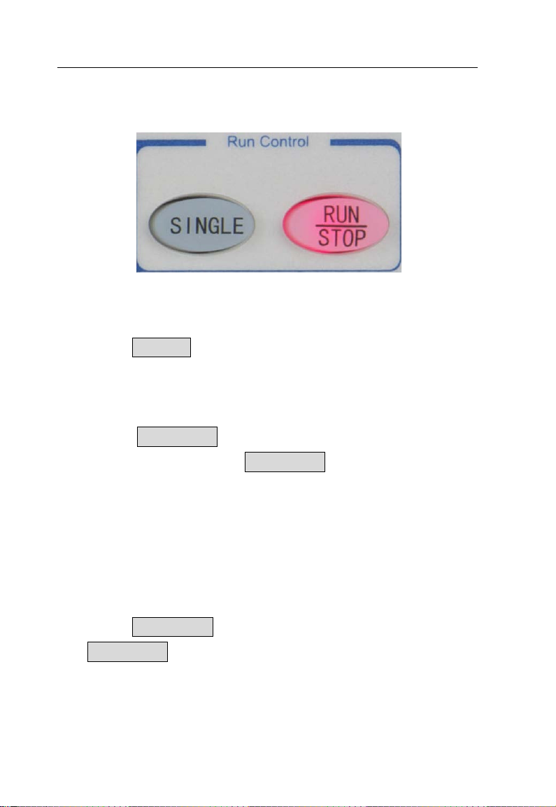
2.6 RUN Controls
Run controls
Press the SINGLE key to execute a single-shot acquisition.
The key will illuminate in orange until the oscilloscope is
triggered.
Press the RUN/STOP key to make the oscilloscope start
looking for a trigger. The RUN/STOP key will illuminate in
green. When the trigger mode is set to Normal mode, the
display will not update until a trigger is found. If the trigger
mode is set to Auto mode, the oscilloscope looks for a trigger,
and if no trigger is found, it will be triggered automatically and
the waveform of input signals will be shown immediately.
Press the RUN/STOP key again to stop acquiring data and
the RUN/STOP key will illuminate in red. Now you can pan
across and zoom in on the acquired waveform.
78
Page 79

Menu Operation
3 MENU OPERATION
• UTILITY Menu
• MEASURE Menu
• ACQUIRE Menu
• SAVE/LOAD Menu
• CURSOR Menu
• DISPLAY Menu
79
Page 80

Menu Operation
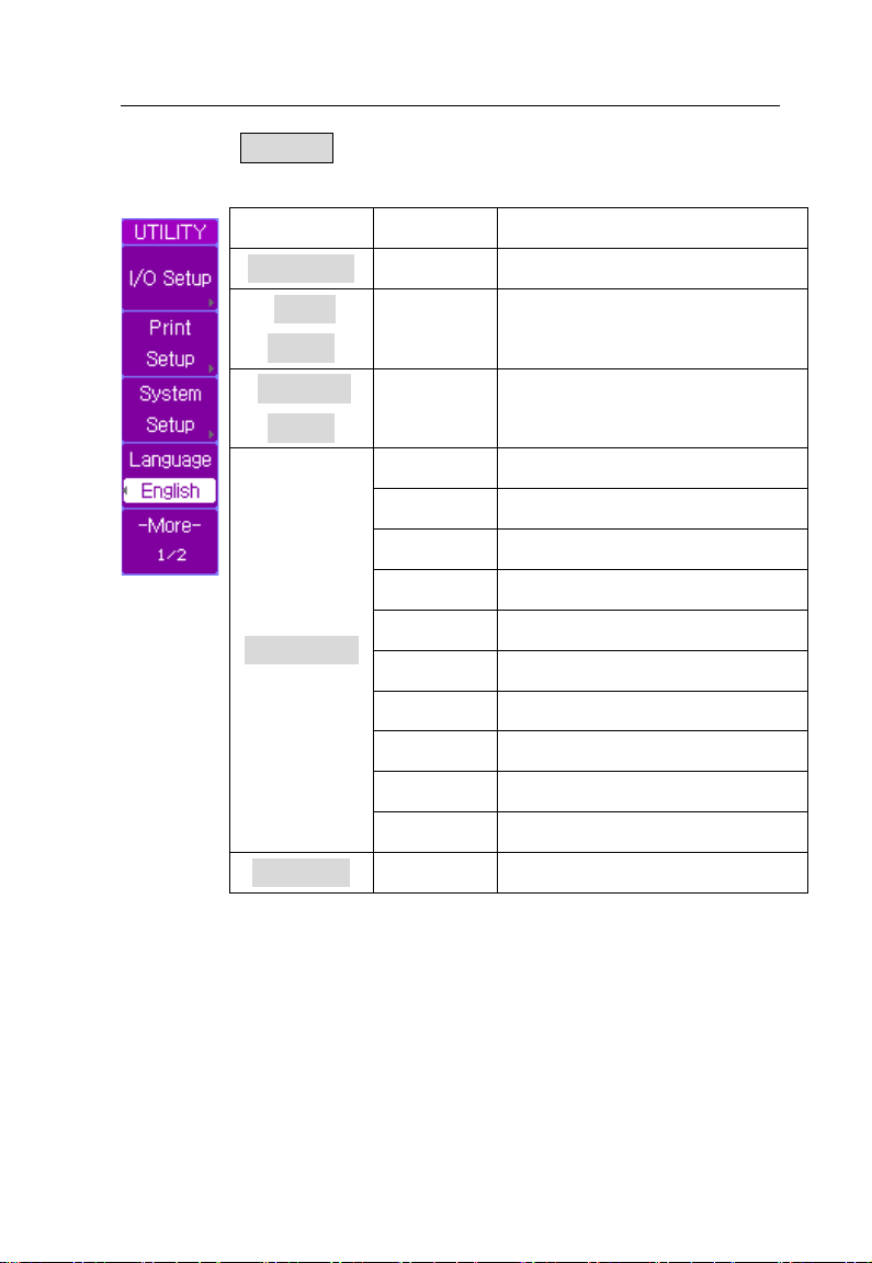
3.1 UTILITY Menu
Press the UTILITY menu key to show the UTILITY menu.
UTILITY Menu key
80
Page 81
Menu Operation
I/O Setup
I/O SETUP
Português
Press the UTILITY key to display the UTILITY menu page
1/2.
Softkey Options Description
Print
Setup
System
Setup
Language
More 1/2
----
----
----
简体中文 Simplified Chinese
繁軆中文 Traditional Chinese
English English language
한국의 Korean language
日本語 Japanese language
Pyccкий Russian language
Français French language
Español Spanish language
Polski Polish language
---- Select menu page 2/2
Select
Select PRINT menu
Select SYSTEM menu
Portugues e language
menu
81
Page 82

Menu Operation
Service
Service
Press the More 1/2 softkey to display the UTILITY menu
page 2/2.
Softkey Options Description
----
Pass/Fail
Self-Cal
Fast-Cal
More 2/2
Self-Calibration
If you want to maximize measurement accuracy, you can
perform a self-calibration.
Self-calibration uses the internally generated signals to
optimize circuits that affect channel scale, offset and trigger
----
RUN/STOP
AUTO
ON
OFF Turn off fast calibration
---- Select menu page 1/2
Select
Select PASS/FAIL
menu
Start self-calibration
Exit self-calibration
Fast calibrate the
vertical position
menu
parameters for all the divisions over the full range.
Disconnect all inputs and allow the oscilloscope to warm up
at least 30 minutes before performing self-calibration.
82
Page 83

Menu Operation
Press UTILITY → Self-Cal to display the self-calibration
page. Press AUTO key to exit the Self-Calibration, or press
RUN k ey to start the self-calibration.
Self Calibration
Note: Warm up the oscilloscope at least 30 minutes
before performing self-calibration. Do not have
anything connected to any of the inputs. Doing
so will create errors and instrument may fail to
calibrate properly.
83
Page 84

Menu Operation
Softkey
Options
Description
USB
Device
Select USB
interface
interface
Available baud
38400
Network
Settings
UTILITY
Fast-Calibration
Fast calibration is ideally used to calibrate the instrument to
remedy the effects of temperature drift causing an offset drift.
It calibrates the center position of each Volt/Div setting, but
not for the full range. This is different compare to
self-calibration, in which the channel scale, offset, and trigger
are calibrated.
I/O Setup
Press UTILITY → I/O Setu p to display the I/O SETUP menu.
Type
Baud
Rate
RS232C
Select RS232C
interface
LAN
---- Select LAN menu
----
84
Select LAN
rate: 2400, 4800,
9600, 19200,
Return to the
menu
Page 85

Menu Operation
↑↓
Press Network Settings softkey to display the LAN menu.
Softkey Options Description
IP address together with
subnet mask and
ON
DHCP
OFF
----
OK ----
----
----
gateway address will be
set by DHCP server
automatically.
You have to set IP
address, subnet mask
and gateway address
manually.
Move the cursor position
vertically (available when
DHCP is OFF).
Move the cursor position
horizontally (available
when DHCP is OFF).
Confirm and apply the
current settings.
Return to the I/O SETUP
menu
85
Page 86

Menu Operation
Follow the following steps to manually configure the LAN
interface:
Set the IP Address. Contact your network administrator
for the IP address to use. All IP addresses take the
dot-notation form “nnn.nnn.nnn.nnn” where “nnn” in each
case is a byte value in the range 0 through 255. M ove the
cursor to the IP address position and change the IP
address using the entry knob.
Set the Subnet Mask. The subnet mask is required if
your network has been divided into subnets. Move the
cursor to the subnet mask position and enter the subnet
mask in the IP address format using the entry knob.
Set the Gateway IP. The gateway address is the
address of a gateway which is a device that connects tw o
86
Page 87

Menu Operation
networks. Move the cursor to the Gateway IP position
and enter the gateway address in the IP address format
using the entry knob.
Set the DNS IP. DNS is an internet service that
translates domin names into IP addresses. Move the
cursor to the DNS IP position and enter the address of
the DNS server in the IP address format using the entry
knob.
Note: If you are manually entering the LAN settings,
you may need to restart the oscilloscope for
settings to apply. If you are using DHCP, first
turn on DHCP, then select OK and wait a few
seconds until the Configure Status shows
“DHCP”. Otherwise, it may not be able detect the
correct DHCP settings from the connected
network. We recommend configuring with
DHCP.
Note: The instrument does not support socket or telnet
connection. When interfacing over LAN, if
settings were changed or refreshed (from
selecting OK from softpanel menu), the
instrument may need to be rebooted first before it
can be connected for remote control.
87
Page 88

Menu Operation
Print to
Print Setup
Press UTILITY → Print Setup to display the PRINT menu.
Softkey Options Description
File Print to file
BMP(8Bit) 8-Bit BMP file format
File Type
Screen
Print To
The P ri nt To softkey option configures what file type to store
when the PRINT key is pressed.
Note: The file can only be stored through an external
USB storage device connected to the front USB
host port.
To store a file to external USB drive, do the following:
BMP(24Bit) 24 Bit BMP file format
CSV CSV file format
Normal Normal BMP picture
Inverted Inverted color BMP picture
Return to the UTILITY
----
menu
1. Connect a USB flash drive to the USB host connector
on the front panel.
88
Page 89

Menu Operation
2. Press File Type softkey to select the file format you
want.
3. Press the PRINT key to save the file to the USB drive.
If BMP is selected, it will take a screen capture of the
display and store it as a .BMP file. If CSV is selected,
it will store the CSV data that represents the
waveform on the display.
Note: The BMP options will print out everything that is
as shown when PRINT key is pressed, including
the opened softkey menu. To get a screen
capture without an opened softkey menu, please
use the MENU ON/OFF key to turn off the menu on
the display before printing to a file.
File Type
BMP(8 bit) – Stores in .BMP file format with 8 bit color
resolution.
Note: Some software or image viewer may not be able
to view this file format.
BMP(24 bit) – Stores in .BMP file format with 24 bit color
resolution.
89
Page 90
Menu Operation
CSV – Stores the waveform data captured on the frame of
the screen into CSV file format. Depending on the timebase,
the maximum number of points that can be stored into CSV is
1200 pts.
Note: Deep memory data cannot be store d into a .CSV
file to a USB flash drive. It can only be obtained
by remote control over USB, RS232, or LAN
interface located in the rear panel of the
instrument.
Screen
Normal – Prints the screen with normal colors.
Inverted – Prints the screen with inverted colors.
Normal
90
Page 91
Menu Operation
More 1/2
Inverted
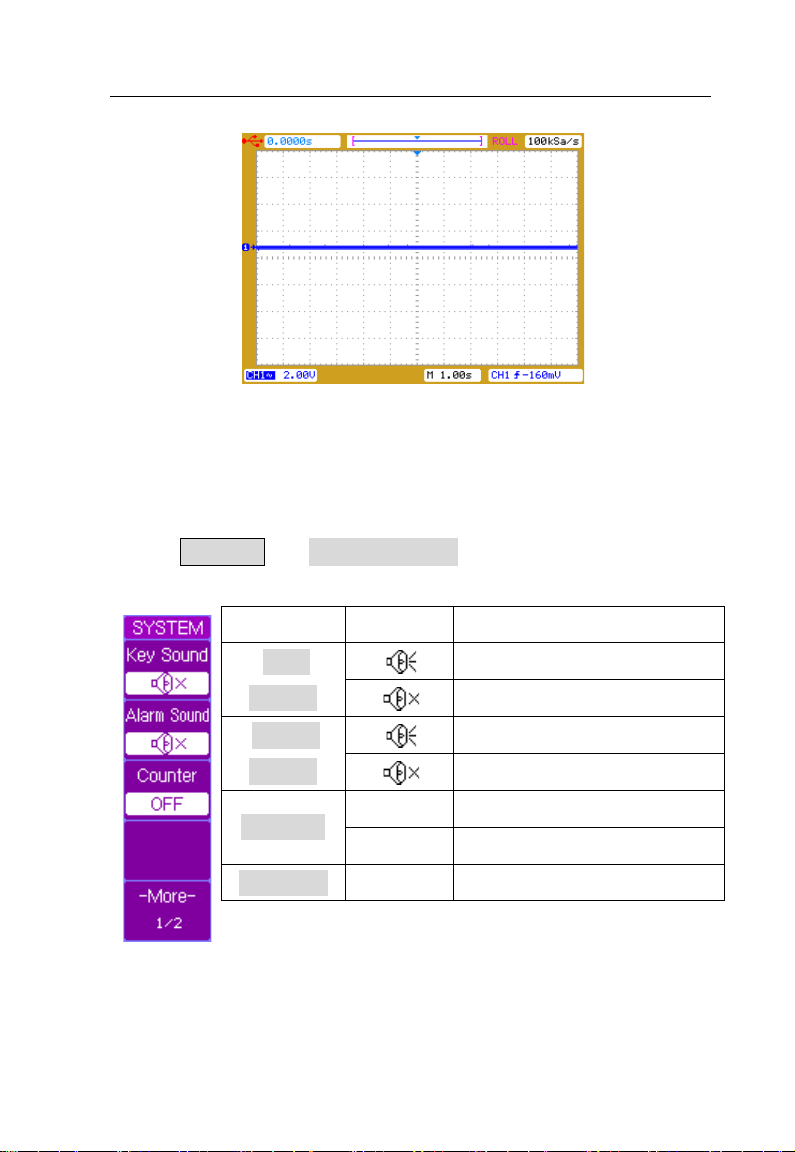
System Setup
Press UTILITY → System Setup to display the SYSTEM
menu page 1/2.
Softkey Options Description
Key
Sound
Alarm
Sound
Counter
ON Frequency counter on
OFF Frequency counter off
---- Select menu page 2/2
91
Key press sound on
Key press sound off
Alarm sound on
Alarm sound off
Page 92

Menu Operation
Frequency Counter
Select the Counter softkey to toggle between enabling and
disabling frequency counter shown on screen.
Press the More 1/2 softkey to display the SYSTEM menu
page 2/2.
Softkey Options Description
ON Key Lock function on
Key Lock
Password
Change
Password
More 2/2
Note: The default password is “111111”
OFF
ON Password protection on
OFF
---- Return to the UTILITY menu
---- Select menu page 1/2
Key Lock function off, a
password is required when
Password is ON
Password protection off, a
password is required when
Password is ON
The old password is
required to change the
password
92
Page 93

Menu Operation
Key Lock
Press UTILITY → System Setup → Key Lock to lock the
front panel operation, all the keys and controls. When key
lock is on, all keys are disabled except MENU ON/OFF key
and the five softkeys. When front panel is locked a red lock
icon is displayed at the top-left corner of the scree n. Corr ect
password is required to unlock the front panel operation w hen
Password is ON as shown below. The default password is
“111111”.
93
Page 94
Menu Operation
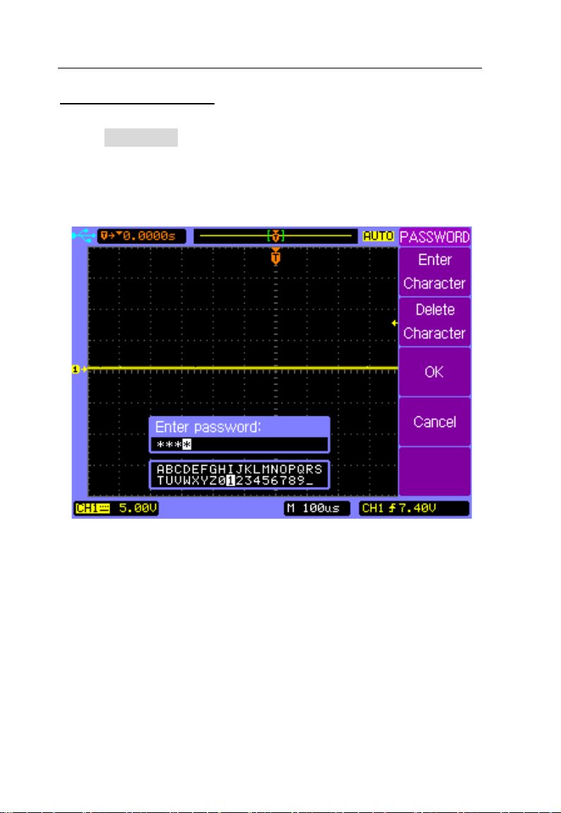
Password Protection
Press Password softk e y f r om t h e SYSTEM m enu 2/ 2 to t urn
off the Password protection function, correct password is
required as shown below.
94
Page 95
Menu Operation
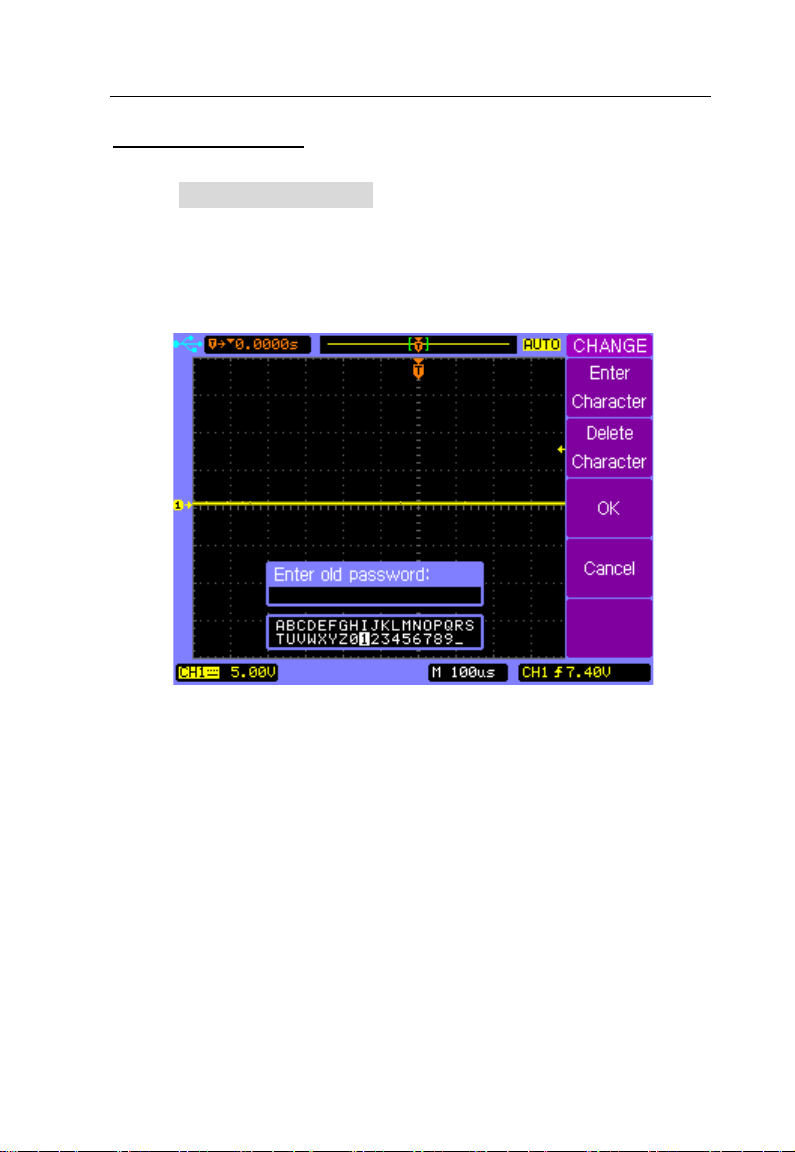
Change Password
Press Change Password softkey from the SYSTEM menu
page 2/2 to display the CHANGE menu. The old password is
required before entering and confirming the new passw ord a s
shown below.
95
Page 96

Menu Operation
k the key and
Service
Press UTILITY → Service to display the Service menu.
Softkey Options Description
Display system
System
Information
Screen
Test
Key Test
information: Model,
----
---- Test the LCD screen
----
----
Serial number,
Software version,
Installed modules
Chec
control operation
Return to the UTILITY
menu
96
Page 97

Menu Operation
System Information
Press UTILITY → Service to display the Service menu, and
then press the System Info softkey to display the system
informations, such as Model, Serial number, Power up times,
Software version and a list of installed modules.
System Information
97
Page 98

Menu Operation
Pass/Fail
The oscilloscope first measures the input source signal and
compares it with Pass/Fail settings, and then outputs the
Pass/Fail result.
Press UTILITY → Pass/Fail to display the PASS/FAIL menu
1/2.
Softkey Options Description
Enable Test
Source
Operate
Setup Mask
More 1/2
ON Pass/Fail function on
OFF Pass/Fail function off
CH1 Source signal CH1
CH2 Source signal CH2
Start Pass/Fail test
---- Set up the regulations
---- Display the menu 2/2
Stop Pass/Fail test
98
Page 99

Menu Operation
Press More 1/2 to display the PASS/FAIL menu 2/2.
Softkey Options Description
Msg
Display
Output
Stop on
Output
ON
Pass/Fail count message
on
Pass/Fail count message
OFF
off
Output on Pass
PASS
waveforms
Output and alarm on Pass
PASS+
waveforms
FAIL Output on Fail waveforms
Output and alarm on Fail
FAIL+
waveforms
ON Stop sampling on output
Continue sampling on
OFF
output
Return to the UTILITY
---menu
More 2/2
Note: Pass/Fail function is not available when X-Y
mode is selected.
----
99
Display the menu page
1/2
Page 100
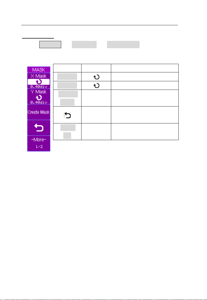
Menu Operation
Softkey
Options
Description
X Mask
Set horizontal tolerance
Y Mask
Create
Mask
Create the PASS/FAIL
tolerance mask
PASS/FAIL menu
1/2
Setup Mask
Press UTILITY → Pass/Fail → Setup Mask to display the
MASK menu 1/2.
Set vertical tolerance
----
More
----
----
Return to the
Display the menu 2/2
100
 Loading...