

Page 1
Triple
B&K 1660
Output
DC POWER
SUPPLY
dlt*rur#ffi.i'
Page 2
TEST INSTRUMENT
B&K 1660
waRl||ltc
SAFETY
Normal
-
electrical
voltage
thlougb the healt
ac
llrs should
curlent under
cause suc-h
habits
higb
voltage, and
contact rpith
know and obselve
1. There
supply.
powe!
use of
shock because
plesent.
is
be consideled
celtain conditioDs.
voltage
should include
a high voltage.
is little
Hoeever,
supply
a. If
b. If the equipbeDt
c. If
the equipment
hazard
equipment
observed.
high
floated
volta_ge
llot float
lespect
ttre equiproent
tage
voltage
retaiD
test equipment
testing
An electrica.I
wilt
stop most hu6an
can laore
all accepted plactices
that wiu
the followirg
dange!
that can
exists
voltage
to the potential
Inay
tbe po.re!
to
ilr aIly
capacitors
high
stee!
thele
unless
does
aot remove
in ary of
appea!
chassis or
oI
voltage
exposes you
ncust
sohetioes
shock
heartbeats.
dangelous
easily
current
You
safety plecautions:
of
electrical
ale sevelal
cleate
utde! test
tbe
under test
at
supply
earth
under
its circuits
before
long
and
Higher
ploduce
will sigtrificantly
a high
equipEent
the hazard),
its cilcuits),
at
the
unexpected points
output
ground.
test
is
unde!
baking
after
the equipraeDt
to a celtain
be perfolrbeal
causiDg
hazardous
voltage poses
a Iethal
that
will
a\eay
is the
is
flom
shock
voltage
point
,off',
IroE the dc
other possible
shock hazard;
"hot
is uDplugged
"powered
the
of connection,
to more tban
(and
nornra.I opelatiotr),
coDnectioDs or
amor,rnt of
\phere
l0
milliamps of
Voltage as Iow
sin-ce it can
an even
culreDt.
prevent
you!
leduce tbe lisk
chassis,,
o!
the
upi
polve!
in defective
tbat equipEent
is tuDed
contact
healt in case of accialental
output of this
test
tvDe. a
plecautions
(arxd
supply
tests.
curlent
as 35 volts
proaluce
gleate!
your
rrith
facto!
conditions using
selious shock
(usi
turning
that
equipEent
outputs
Remeober
equipbeot.
100 voit;
uses high vol_
discbalge higb_
SoEe cilcuits
off,
dangel floh
exposeil
tltleat
normal
ot Jtep
peak
high
pass
to
dc o!
a lethal
work
exposeal
if
power
off
g
uses
may be
that high
with
be_
you
this
the
are
Do
Z.
Use olly a poladzed
cha6sis,
reduces dange!
3. DoD't
neceasaly,
cilcuits.
4. lf
possible,
cation of
appear at rEerpected
case, and ground
expose high
Discbarge
its high
3-wi!e ac
telrainal
florD
electlical
vottage
T[ra off
higb-voltage
faEiliafize youlseu
voltage points.
{codtinued
neetllessly.
equipEe[t
poiuts
in delective
outlet.
ale conlected
shoclg
Remove
while
oa inside
Eaking
capacitols
with
the equipE
However,
This assures
to a
bousiags
test coDnectioDs
after
reEo\ring
ent beiDg testeal
letlembe!
equipmert.
rear
cover)
that the
good
aDd covels
powe!.
tbat high voltage
powe!
eartir
Stounil
only whea
in higb-voltage
and the
supply
anil
lc_
Dlay
Page 3
lnstruction
B&K 1660
Manual
for
Jt1}lr,
Model 1660
Triple Output
DC
POWER SUPPLY
s(t^Ect--,t
MAXSE9 TNTER
ATONAL
CoPrr.
H( PEECES'-,J
MAGg
w
6470
TNTEFNAIIONAL
Corlland St . ChlcaSo,
coFP.
lL6O635
Page 4

TABLE OF CONTENTS
B&K 1660
page
TESTINSTRUMENTSAFETY.
INTRODUCTION
FEArijllES
sPljcii::a-.!
CONTROLS
General
4-6.5
Ma.ster Suppl-v
Slave Suppl-v
r:lN:-i.
INDICATORS.
AJI
Conttols And lndicators
\'supply Controls And lndicators.
Controls ,{nd lndicatols .
Controls And Indicators
Rea-l Panel Controls ..
CPERAT]NG
Safet-v
Equipment
lndependent
Series Tracking
Pa-rallei
,1-6.5
INSTRUCTIONS
Prec:.rrtions
Precauiions
Use Of
"Master"
Opelation.
Tra.cking operaiion
V Poirel Supply Opelation.
APPLICATIONS
Generat..
Electronics
Servicing .
Electronics Manufacturing
Elec tlonics
Design Lab
. . . . .
Electlonics Education.
Battery
Split
Charging
SuPPI-\'
"S1ave"
Or
.
. , . .
. . . , .
SupPl]' ...
..
, . irside
front
., ".......I
.... .,,'4
..... -...
........
.........5
. . . . . . . . 5
. . . '
......
......
.....,,,,,9
...... ,9
.............9
..
.. ......13
.....'.16
.'......''.'.19
......,..,.
...'.........20
............20
.........20
. ' ' ' '...21
..... -.. ZI
.,..........21
coier
.......3
.. 5
.
., .
.?
'. . . .. .8
...
ZO
. ...,Z0
9
MAINTENANCE.
Replacement
Fuse
voltage
Line
Conversion
Adjustments.
lnstrument
Repai! Service.
WARRANTYSER\TCEINSTRUCTIONS....
UMITED ONE.YEAR
WARRANTY
.,.....
"..25
......
',.,...
..' .
--.. 25
...--26
... .'.'.30
......31
.............32
25
Page 5
INTRODUCIION
B&K 1660
Tbe B & K-hecisi@ Model 1660 Triple
Output DC Powe! Supply is a higb
genela.l purpose
two supplies
ong with a 4-6.5 volt dc
supplies are adjustable with
fine voltage
and are capable of current output of
0-2 arops. The 4-6.5 v supply
output of 0-5 a.Eops, allowillg it to hanille extensive digita.l Iogic circuitry. Two la.rge
palel-Eoormted
tor eithe! the
o{ each supply.
The
independendy or in
r:oodes. In the
supply
supply, MaxiEuo
supplies can still be set independently \rhen in
the selies tlackitrg
seri€s tlacking
supplies a.!e connected in se es, allowing a
singie output of 0-60
patallel
connected
gle
constant
caiioDs. The clossove! floB constant voltage
to constant
autoEatic. LED'S indicate tbe
voltage) or
operation. In constart
curlent limit loay
ations cause
lioit, the
lathe!
adjustable frorD 5% to 10070 oI b:axixouEr. IrI
constant current applications, the
voltage may be
cause cuJrent to
value,
oDeration at the Dreset value,
digital logic circuitly, The 0-5 allp capacity
tracks the voltage of the
0-30 V output
Both 0-30
tha!
the
The 4-6,5
with a 0-30
contlols
output
two 0-30 volt
tlacking
together iD
voltage o! constart cutrent appli-
cu.!!ent modes is sEooth a.nd
"CC"
the c{rlent to reach the
unit then regulates output cu!]ent
output
unit reverts to legulated voltage
power
dc
LED oete! displays caD moEi-
selies tlackilg Eode, the Slave
curlent settidg of the two
mode
Eode,
at up to 4 amps.
volt
supplies
(corBtant
be
voltage.
preset.
dlop below
V supply is ideal for
soulce. It
volt dc output and
output. The 0-30 v
both coarse aJId
precise
for
has a current
curtent
supplies can be opelated
one of
operating 6ode, In the
V at up to 2 aDcps. In the
parallel,
preset,
or output voltage
two
Maste! aIId Slave
the
the two supplies ale
allo\ring a sin-
may
"CV'
cu!!e!rt) l3ode of
voltage applications, a
when
Cullent liloits are
When load valiatioas
the
quality,
provides
settability
tlackilg
Ma.ste!
be used itr
(coDstant
va-ri-
load
preset
rDaxirDurD
legulated
powering
allows tbe supply to
cuits, Built-in ovelload
matically liEits to cutiebt output to a Eaxiloull] of 5 aEps. An indicato!
supply is ovelloaded,
The Model 1660 exhibits excellent
Iation ard low
design
cuit
greatly
low output
dedtal daEage to the
ploper
curreat lioitilg
powered,
earth
comections. Wbed needed, the
Iality llay be stlapped to
polarity
tage. Additiona.Uy, the two 0-30 volt supplies
can be used as a
tive
aegative voltages and a cotDllon
one
of these coiligurations
datching
voltages.
especially tbe triple output
featues, make it an ideal
powe!
catioas. It can serve as a single
voltage
ply,
equipEent. It can
taneously
ation.
tages
may
power
temoved
evafuated vrhile
Drototv'De cilcrdt to
leduces intelnal
Revetse
coDnection to a.a extelnal voltage, and
as weII aE the
output is isolated flou
The
glound,
!!ay be floated to an extelnal vol-
voltages and
positive,
(tlacking)
features aJId versatility oI the unit,
The
supply for engineering lab applipowe!
fo!
breadboard
valying voltages for ctcuit eva.lu-
It can
fo! evaluating diffelential aEplifiers. It
be used as a battery
individual circuit boalds o! caril6 while
llom the systeh, Its output ca'I be
pple
incolpolates
voltages.
polarity protection plevents
plotects
which
otre negative, and a cor!6on. AII
source, including tbe
provide
be used
charactelistics. The ciF
pre-legulato!,
a
powe!
poi/ef
the equipEeDt being
power
p€lmits
"split
supply" with two
a comDon negative, two
ca]l be
or dif f
and
Fotot]?e
provide
tracking
poweling
determine the cilcuit's
for large ci!-
protection
lights
supply
supply.
full
glound,
used
eling
genefal purpose
single o! sillul-
eliminator,
a bleadboald or
when
dis6ipation
lroE iE-
chassis
flexibility of
(+)
o!
o! either
positive,
with
{independent)
and
tracking
o! multi-
bias
circuits and
(+)
and
(-)
auto-
the
regu-
whic-h
acci-
alrd
(-)
po-
posi-
eithe!
suF
vol-
or
at
or
to
Page 6

INTRODUCTION
B&K 1660
powel
quality
suppty requi!emerts.
Its labo!atory
specifications will loeet most engi-
neering labo"a.tory requi!ements.
The same featules that make the Mod€l
1660 a
good
choice fo! a]} engiaeeling lab also
Dake it a
state
good choice
electronic applications.
cations include selvice
fo! dost other solid
shops;
duction testing of coDrponents'
collplete equipment;
home use bv electronic
and
fo! school labolatolies,
hobbyists.
These apPli_
industrial
Pro-
assembli€s, and
Page 7
FEATURES
B&K 1660
TRIPLE OUTPUT
Operates
Eacb
isolated
,{
ONE
Husky 0-to-5
ideal
circlritly,
extensive
TWO O-30
Master and
variable
and fine controls.
current
as thlee separate
has floating output
flom the other
TO 6.5 V SUPPLY
amp 4-to-6.5
fo! use
with Dost di$tal logic
Adequate cuilent capacity
circuitly.
VOLT SUPPLIES
Slave supply are continuously
ovel 0-to_30
Each supplv has a Z amp
capacity.
and is completely
two.
volt
range with coarse
UMQUE TRACKING FEATURE
The two
0-to-30 V supplies can
so that the Slave supply tracks
supply. Outputs
positive
voltages
two negative
tive, or one
a neutra.l
common.
SINGII G6O
Series
and Stave
tracking feature
supplies
V SUPPLY
can be strapped
with a comDon
volLages
dith a common
positive and
allows use of Master
as one 0-to-60 V. Z alnp
one negative with
supply.
SNNGIJ
O_30 V 4
Palallel
Maste! and
supply
(through
CONSTANT
with
AMP SUPPLY
tracking
feature allows
Slave supply as
a :1 amp current capacity
MasteF
output terminals)
VOLTAGE OR CONSTANT
CURRENT
The
Master and
regulated dc
voltage output or regulated
slav-
power
supplies.
volt suPpty is
for
be operated
the Master
fot two
negatrve)
posi_
lise of
a 0-to'30
.Lpplias pro! d-
dc
.urent output- Crossover is sEooth
DISPLAY
LED
Two large, easy-to-read
displays monitol outPut
cu.relrt of aU three
meters allows
voltage
Slave supplies
visiblilty in
auows
LABORATORY
Excellent
LED INDICATORS
Identify
PRE-REGULATOR
Limits
reliability
ISOLATED
Either
OVERI-OAD
Fullv
to 100%
Vaste! and Slave
under
V
REVERSE POLAR.ITY
Prevents damage
external voltage
HOOK.UP
,supplied
hook-up
supplies.
simultaneous
metering when
in tracking
bright
resolution
o!
loq
of 0.1 volt or 0.1 amp.
QUAIITY
!eeulation.
mode
of ope!ation.
1o$ tiPPle.
internal dissipation
and ef f iciency.
OUTPUT
pola.rity
be floated or
may
PROTECTION
adjustable cullent
of mdimurn output
supplies
test and the
er suPPlY.
Poq
PROIECTION
porter supplv
to
of revelse
CABLES
with three
sets of red
leads.
and
LED 3-1l2
digit
voltage or output
Use of two
current
M3ste! alld
use
oPeratioD.
light.
and
Good
Meter
{o! hiehe.
grounded.
limiting
(from
5%
curentl lor
protects
circurt
lrcrm
polaritv
ard black
Page 8
SPBCIFICATIONS
B&K 1660
ITASTBR AND $../lVE SUPPLIT-S
outFt
OutFrt
Load
LiDe R*ulatioD 108
vortrge
0 v
{+0/-30
Curl€ot
(+0/-30
0 A
Regulatio!
<0.01%+
3 bV.
Rage,
mv)
to 30 v
Lieit
Rdge:
EA) to 2 A
(Cdstart
-
132 V
(3
+
+(3Vo
to 7Vo).
Voltage):
(Consta"r
Voltage):
<
0.01% - 3 bv.
Rittrtle
Recoeery
Tehlr
Load R€gulation
Lile Reguration
(CoDsteDt
<
I EV RMS.
TlEe
<
loo
ss'
Coclficieot
=
ppb/oc.
3OO
<
0.2Vo
+3
Voltag€): Peel Meter Accuract':
(Constart
(C@rtart
(CcE3ta[t
Voltage):
Voltage):
CrErent]:
mA-
108 - l3z
(c@start
v
CErent):
<
Rilple
O.Z7o
Cr|f!€ot
+3
E'A.
(at
108
V Io!
CoDstant
Crttfeot]:
<
3 IlA RMS.
Tbackiry
t1.Zqo
P&el lileter
i0.5% + 2
(S€ries):
+10
nV,
Accrracy
digits.
(volts):
b 1qo)'
--
Load Reeulatiod
ov
(0
=
l0
Lire RegutatioD
(C@start
to 5 A load)'
-
108
l3z v
Vottage):
(coEtaDt
VoltaSe):
<10
DcV.
Ripple A.!d Nobe:
=ZrbVRMS,
OvelYoltage hotection Thteshold:
Same as Maste!
Suppiy Mete!.
cENERAL
Poeer
po;'er
RequireEents:
110/1zo/220/z4o
vAC
CoDsurnptioD
ApproxiEately
320
!1070. s0/60 Ilz-
(FuIy
Loaded):
\4t'
hotection:
Revelse poladty
protection
liEiting.
DiDeDsiors
165 x
(E
:< Y r D):
315 x 381 bra
(12.4
x 15 x 6.5"),
E'eigbt:
10 kg
(22
lbs)'
and cur!ent
pdel
,F&5
OutFrt Volt.€e
Metet
% + 2 digits.
J0,5
V
SUppLy
4
Y
t57o
to 6.5 V
Acc|racr
RaDg€:
r5Vo.
(cEreDt):
TffiS,"Tff;?up
Two
ea.rth
Two 5A, 250V
Schematic
Ootionel
Fp-tO l6-amp test
ground
DiagraB &
Accessori€3:
bus
fuses
leads, I !ed,
stlaps.
(spares),
palts
leads
List,
(t
red, 1
I black.
black).
Page 9
GENERAL
B&K 1660
CONTROLS AND INDICATORS
1. POWER
off, When
nally iuuEi ated
Z. TRACKING
button switches
oode, series
t!acking
a. When
(out),
dent
SLAVE
pletely ind€Pendent
anotDel,
When
b,
and
(out),
SERIES
mum
using the MASTER
tlols
of the SLAVE
tage
MASTER
roode
terminal
is connect€d
nal
This a]lo\rs the
used as
When both switches
c.
(in),
PARALLEL
MASTER
wiled
the
are set using
trols.
outputs
vidual
or
used
4 A capability,
(F30
3.
V/+6.5
TER/,1-6.5
switch is
CONTROLS AND INDICATORS
Ssitch-
powel is
Mode
mode
both
the
mode
Tutns
Power
on, sxitch
to
serve
as a
Seitch€s.
select INDEPendent
that
tlacking
follows:
as
mode, or
switches are
unit is
in the INDEPen-
arld the MASTER
power suPPlies are com-
the left switch is
the right
the r]nit is in
mode. In this
voltage of
switch is
the TRACKING
mode, maxi-
both suPPlies
VOLTAGE
(voltage
outPut telminals
at
supply ttacks
at the output
supplvl.
of operatiod
(red)
to the
(blackl
of the MASTER supPly.
teloinals
AIso. in
the
of the sLAvE supply
negative termi-
two suPplies
one 0- to-60
volt suPPIY.
ate engaged
the uiit is
in the TRACKING
rnode, ln this dode
SLAVE suPPlies
and
together in
maxilouE
palallel
cuirent and
the MASTER
MASTER alrd
The
can be used
(but
tracking)
just
the MASTER output
as two iDdi-
power
as a 0-to-30 volt supply
position'
V
Controls
V Ssitcb
V LED
in tbe G30
DisPkY.
and
on
is inter-
light.
Pilot
push-
Two
Parauel
disengag€d
ard
llom one
engaged
disengaged
is set
con-
voi-
the
of the
this
Positive
to be
both
and
voltage
con-
SLAVE
suPPlies
can be
with a
MAS-
wlen this
the LED
(in)
the
a.!e
display looniiors
when this
position.
V
Switcb- Selects
mode for the
the
.1.
supply,
tr-5
the 4-6.5 \' supply.
tors
A/V
meterirg
supply or
oD setting
When
read from
in the A
the
play. When in
tage is
LED
MASTER/4-6.5
5.
dis?tay
the O-30
supply
read
Dispray.
indicates
v
MASTER
(depending
MASTER
4'6.5 V SUPPLY
INDICATORS
'-'
6.
?.
Tedrinal
output
"+"
T€rniral
terminal
output terminal
8.
Voltag€
Level C€'rtrol.
voltage to!
terclockwise
4 V. Clockwise
voltage to a
clockwise
4_6.5
9.
tage to
cleases
(full
A OVERLOAD
5
load on
1arge.
MASTER SUPPLY
INDICATORS
(CoDstant
C.C.
10.
the
lights
ConstaDt
LED
MASTER
the
switch
disPlay
LED
the
current
MASTER
,F6.5
of
(amPs)
(F30
V supply
V/,1-6.5
position, cu.rlent
MASTER/,|6.5 V LED
the V
(vo1ts)
from the
v LED
voltag€
supply
on the
A,/V aid
CONTROLS
(Blact).
for 4-6.5
(Red)-
4-6.5 v supPly.
for
position'
MASTER/
Dispray. Digital
or cuffent
or the'1-6.5
setting
0.30
AND
Negative
V suPPIy'
Positive
Adjusts
4'6.5 V
!otation
supply, Fully
adjusts
rotation
maximuEr
rotation).
IDdicatot.
Volt suPply
CONTROLS
Crr'ledt)
becoloes
AND
Irdicator.
when MASTER
Cu$e$t
mode'
(0-30
is i!
moni-
cr voltag€
0-30
(dep€ndiBg
switch).
V
Dis-
vol-
'F6.5
of the
V/4'6.5
Polatity
Polarity
output
coun-
otttput
of 6'5
Lights
SUPPIY
when
is in
The Powe!
V)
the
v
is
V
at
v
'V
voi_
in-
v
too
Red
Page 10
CONTROLS
B&K 1660
AlfD INDICATORS
-l
I
66
0l
Supply
the va.Iue
control.
when
MASTER
Constant
11.
C.V.
LED lights
ir the
Power
tage
VOLTAGE
or Parallel
dicator
SLAVE supplies
tage
rz.
COARSE
adju.stment
MASTER
coarse adjustEenr
Eouh output
when eithe! paraUel
regulates
this indicato!
(C@staDt
Constant
Supply
at the value
is lit, both
mode,
26
25
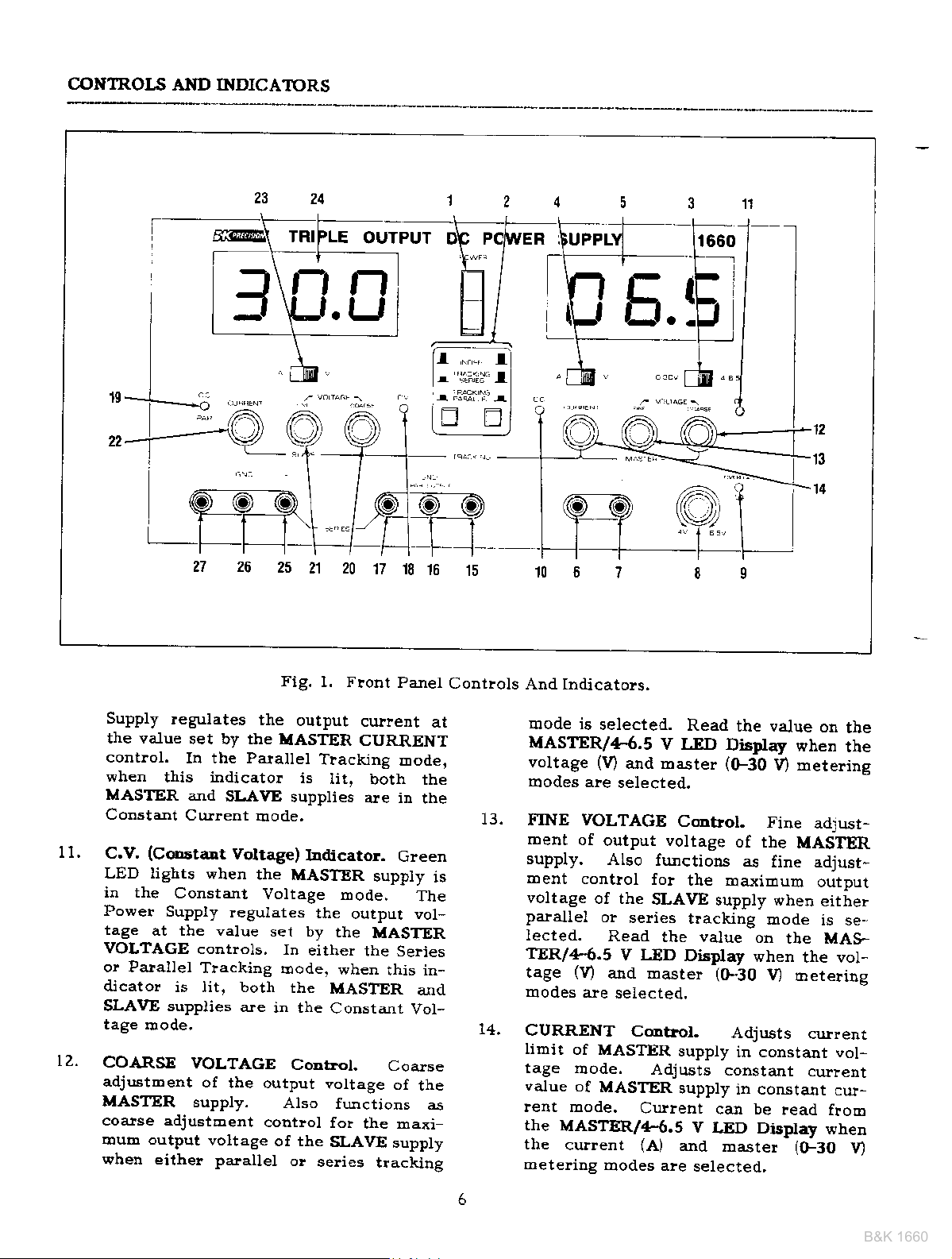
Fig.
l. Front
the
output
set by the IIASTER
In the Parallel
aJId
SLAVE
Current
when
controls.
Tracking
VOLTAGE
of
supply.
Eode.
Voltage)
the MASTER
Voltage
regulates
set by
are
the output
coutlol
voltage
Tracking
is
lit,
supplies
Iadjcator.
the
ln
erther the
Eode. when
the
MASTER
in the
of the
Corttol.
vottage
Atso
o!
seli€s
CoDsta.nt
fo!
SLAVE
2021
17
Panet
culleDt
CURRENT
both trle
are in
Green
suppty
mode,
output vot,
the
MASTER
SeFies
rhrs
Codse
of
functjons
the maxi
supply
tracunp
I8
Eod€j
rne
The
in-
alrd
Vol-
the
a
ti;
'.li+:,.
r
E
15
Contlols
at
is
f
I
EI
And Indicatols.
Eode is
MASTER/4.6.5
voltage
modes ale
13.
FINE VOLTAGE
ment
supply.
Dent
voltage
palallel
lected.
aE.R/4.5
tage
IIrodes
CURRENT
Iimil
tage rDode.
value
lent mode.
the
MASTER/4.6.5
the
metedng
E
selected.
iv)
and master l(F30
selected.
of
output volrage
A160
control
of rhe
ol
rV)
are
of MASTER
of
MASTER
current {A)
modes are
firnctions
fo!
SLAVE
se es
Read
V IlD
afld Daste}
selected.
C@trol.
Adjusts
Cutrent
I
Read
V I,ED
Cmbol.
the value
Distr'lay
the
Ea-{iEum
suppty when eitier
trackiDg
Display
,(F30
suppty
constant
supply
can be
V
LED Display
and
rDaster
selected,
l
3
l3
l4
the value
Fine
of the
as
fine adjust-
mode
on
when
l/
Adjusts
in constant vol-
in constant
on
when
V) Eeterins
adrusr-
MASIIER
outDut
is se-
the MAS-
the vol-
meterins
currenr
curlent
cuJ-
aead ftolc
when
((F30
the
the
u
Page 11
CONTROI.S
B&K 1660
AND INDICATORS
'+'
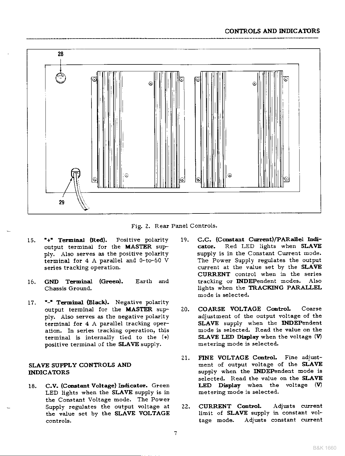
15,
16. GND
17.
TerEiral
output telminal
ply. Also serves
terminal
series
Cbassis
'-'
output
ply.
telroinai
ation.
telminal
positive telminal oI
tlacking
T€fmiDal
T€rminal
AIso selves
(Re(l).
for 4 A
oPelatiotl.
Ground.
Elack).
telminal
for 4 A
In series
is intelnally
o
€
Fig. Z. Reat
Positive
fo! the
as the
palallel aJId 0-to-60 V
(Green).
for the MASTER sup- 20.
as the negative
palallel tlackiDg opeF
tlacking opelation.
the SLAVE suplly'
MASTER suF
Positive Polarity
Negative
tied to the
polarity
Earth
polarity
Polarity
o
Panel Controls'
aJId
this
{+)
19.
C,C.
cator. Red LED
supply is in the Constant
The Powe! Supply
current
CURRENT
trackiag
lights
mode is selected.
COARSE
adjustment of the
SLAVE
mode is selected.
SLAVE
meteling rDode is
(C@stant
at the value set bv the
contlol
o! INDEPendent
when the TRACKING
VOLTAGE Cdlrol,
supply when
DisCay when the
LED
Curr€.rt)/PARalle-r
lights when SLAVE
Culreirt
legulates the output
when in the selies
modes. AIso
PARALLEL
outPut voltage
the INDEPerdent
Read the
selected.
value on the
voltage
I
t-
mode'
SLAVE
Coarse
of the
(9
SLAVE SUPPLY
INDICATORS
18. C.V.
(CoD3taDt
LED lights
the Constant
Supply
the value set
regulates
CONTROIS
Voltage) Indicato!.
when the SLAVE
Voltage
by the SLAVE
AND
mode. The Power
tle output
Green
supply is in
voltage at
VOLTAGE
21.
FINE
xoent of output
suppiy
selected.
LED Display
Eetering
22.
CURRENT
limit
tage
VOLTAGE Control.
voltage of the SLAVE
when the INDEPendent
Read the value
when the
mode is selected.
C@trol
of SLAVE supply
trode. Adjusts
Adjusts
in constant
co$stant
adjust-
Fine
Eode is
on the SLAVE
voltage
19
curent
vol-
curlent
Page 12
CONTROLS
B&K 1660
AND INDICATORS
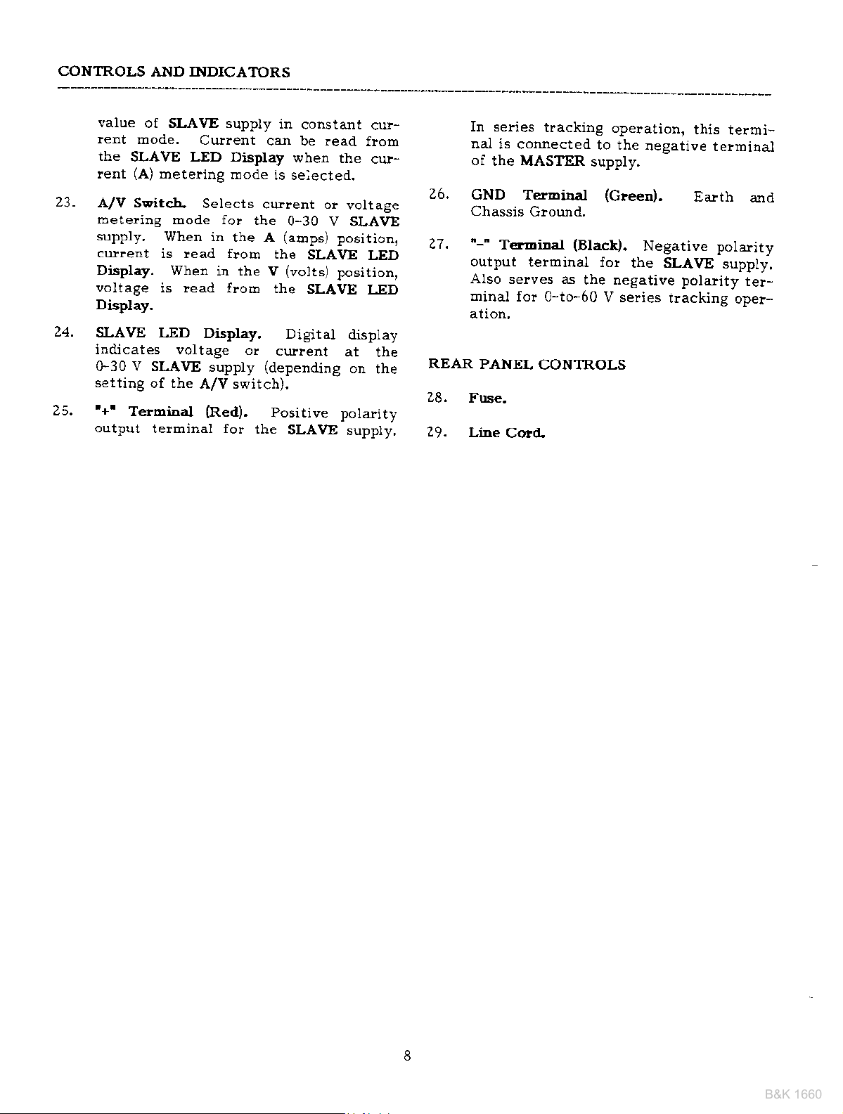
23.
24.
25.
value
rent
the
lent
A/V SFitc-b.
metering
supply,
culnt
Display. When
voltage
Display.
SLAVE
iddicates voltage
0-30 V sl-AvE
settiDg
'+'
output
of SLAVE supply
mode.
SLAVE LED Display
(A)
of the
Tetbiaal
telminal for
Current
metering mode
Selects
mode for
When in
is lead from
in the v
is read lrom
LED Display.
supply
A/V switch),
(Red).
in
can be .ead
is selecled.
current or
tbe
the A
the
the
or
current
(depending
positive
the
constant
wher
0-30 V
(aqlps)
SLAVE
(volts)
SLAVE
Digitat
SLAVE
cu;!,
from
the
cur,
voltage
SLAVE
positiotl,
LED
position,
I-ED
disptay
at
the
on
the
potadty
suppty,
26.
27.
REAR
28.
29.
In series
nal
is connected
of
the MASTER
cND TerEciDa.l
Cha.ssis
"-"
Terminal
output
AIso
miDal
PANEL
Fuse.
Line
tracking
Ground.
(Blact).
terminal fo!
selves as
Io" 0-to-60
CONTROLS
Cold
operation,
to the
supply.
the negative polarity
negative
(c!een).
Negative pot:rity
the SLAVE
V series
this
terminal
Ealth
supply.
tracking
termi*
and
te!-
opeF
Page 13
OPERATING
B&K 1660
INSTRI'CTIONS
SA.FETY PRECAUIIONS
cAuttoL
Avoid
at the
Wben the unit is
a&ounts
of its outputs,
becoEe
the heat sinks
could
damage to the equipEeEt in contact
Use only
outlet.
power supply chassis, case, and
ground terEinal are connected
to a
duces dange!
shock.
There Eay be
electrical shock if the
supply
extelDal
equipdent beiDg
contain
a sbock
cautioD, Ii the
output is
a voltage ratbe! than earth
grotllld)
supply
test
Never float the
a
100
eattb
EQIJIPXENT PRICAUTIO
Avoid
teEpelatures above
sufficient air space
lear of
tior to
prevent
contacting
oI the
lear
of cu$ent
the lteat sinks can
very hot. CoDtacting
when
lesult itr skin burDs o!
with thetn.
polarized
a
This assures
good
earth
output is conDected
high voltage.
high voltage and
hazald"
floated
turn off
a.Ild
the
when making connections.
potential
volts
rising the
the
peak
ground"
powe^r
+40"
alound
powe!
supply
internal heat build-ul.
the heat sinks
power
ploviding
ground
flom
great
poweled
power
(lefelenced
equipEelt
power
gleat€!
with lespect
for
supply,
large
at any or all
ale
they
3-wi!e ac
that the
and re-
electlical
danger of
powe!
to
SoDe
plesent
Obse!ve
supply
power
the
uDde!
supply
S
supply
C. Always allow
heat
the
effective ladia-
hot
an
may
to
to
than
to
ambiert
in
sink at the
Althottgh the
against
being
tection.
incoffect
under test.
cuit being
integrated cilcuits will not
spikes
under
terEinal,s of the
the
turtted on or off.
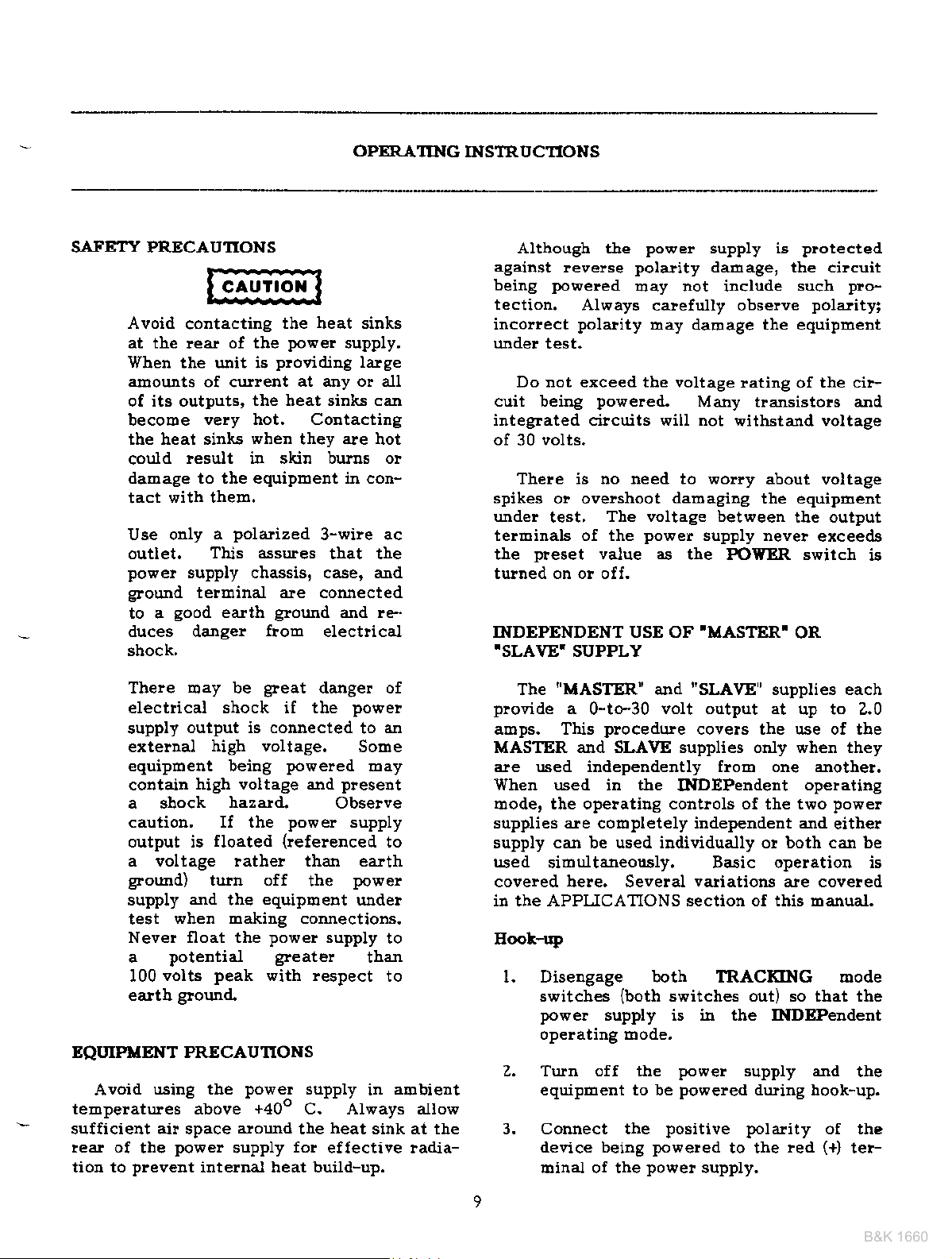
INDEPENDENT USE OF
.SLAVE'
plovide
aDps. This
MASTER ard SLAVE supplies only when they
are used independently from one another.
When used in the
mode, the opelatiEg contlols of the t\ro
supplies are colt|pletely independent and
supply can be used ildividually o! both can be
used
covered be!e. Several
in the APPLICATIONS section oI this Eanual.
Eool-r{)
l. Diseugage both TRACKING mode
2. TUrn off the
3. Condect the
levelse
powered
Always
polarity
Do not exceed tbe voltage
powered-
There is tro $eed to wo!!y
o! ovelshoot
test.
preset
The
sidultaneou.sly. Basic operation is
switches
powe!
operating rbode.
equipEent to be
device being
llinal of the
value as
SUPPLY
"MASTER"
a
0-to-30
power
polarity
Eay not include
calefully obselve
loay
The voltag€ between
power
and
volt output at
plocedure
(both
supply is in the INDEPeDdent
powered
powe!
supply is
daEage, the cilcuit
daEage
rating ot the ci!-
Many transistots and
*ithstand voltage
damagiDg
supply neve!
the POWER switch
'I,ASTER'
"SLAVE"
covers the use of tbe
INDEPendent
vadations
switches out) so that the
power
poweled
positive polarity
supply and
to the
supply.
protected
such
the equiprdent
about voltage
the equipEent
tbe output
OR
supplies each
up to 2.0
are covered
during hook-up.
red
PIo-
polarity;
exceeds
opelating
powe!
eithe!
the
of the
(+)
teF
is
Page 14
OPERATING
B&K 1660
I !.!
INSTRUCTIONS
,l
rE.[
_'1
f'l a'1 1 | t- t-
lt
s.u
l-',r.f,
I
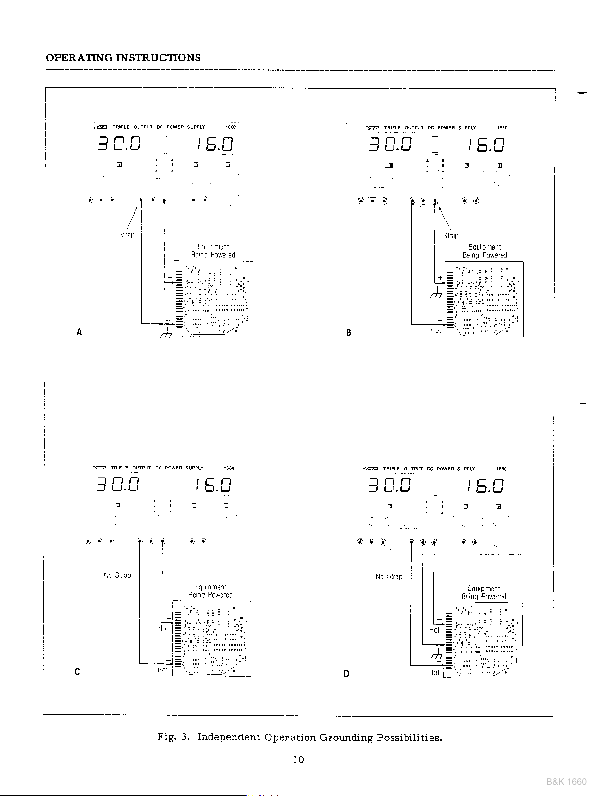
Fig.
3. Independent
f D,D
Operation Grounding Possibilities.
10
Page 15

OPERATING
B&K 1660
INSTRUCTIONS
i[.
Connect
device
terminal
Fig. 3 illustlates
5.
ities
6, Observe
being
verse
circuit
Use color coded
the sets
for convenience
red for
when used in the INDEPendent
a. If t]re
equipoent
is
may
stlapping the
the
in Fig. 3A.
b. Similarly,
be
terminal
miRal as shown in
c. If
required, the codfiguratio. of Fig,
3C
Fig. 3C should
is
common wiih either the
negative
d. If the
equipEent
r^fF fr^m hoih thF Dositive
negative
the connection
polarity plotection,
negative
the
being
also the chassis
groulded
aI} ea-lth
not krown whether the chassis is
poweled
can lesult
(+)
povreled
of the
g!€en
may be used. The scheEe in
ploper
supplied
powe!
the
negative
ol
glounded
be
(GND)
the
by strapping the red
to the
$ourd
polality,
chassis or
being
polarity
pola.rity.
not equipped with re-
is
hook-up leads, such as
\tith
in
and black
pola]ity
to the black
supply.
glounding possibil-
polality
ctcuit
black
positive polarity
also be used where it
froE reverse
being
o!
to eatth by
(-)
teroinal as sho\rn
gleen
Fig.
3B.
refer€nce is not
common of the
powered
power
shown in Fig.
II
darnage
powe!
the
identifying
(-).
for
of the
of
powered
common,
telminal to
(GND)
Positive
is sePa-
inputs'
3D.
cilcuit
the
to the
polarity,
supply'
polarity,
the
can
ter
and
use
H
it
(+)
o!
device
limit
Set FINE
imu&
Turn off
3.
procedure
position
Increase
6.
7.
value
n'^.o;!!i4 in ihi< c..ri^rl
and
COARSE VOLTACE
(f
the device to be
Turn on POWER switch. The CV
cato!
should light.
Set the meter selection
mode.
LED display
FINE
specific
Set the
position
mode and note the
display.
control
Fead oulPrt !c iaQe
a'ro currsnl
powered
to be
{see
VOLTAGE
ully cotrnterclockwise).
power
in this section).
to
the
value,
meter selection switch to the A
to select the cu$ent oetFring
suppll' and corurect
select the
VOLTAGE setting until the
rea.ds the desired valu€. The
permits easier setting
lrom dspa!
\i
and set the cutlent
"Setting
control
powered
v^'tae-
load curient on the
\l
oc 4{EF sumY
- '_]
I [.C
t.rl:
CuFent
control
(see
switch to the
CV
Limit"
to c€nter
ro:rin
"Hook-Up"
r0cai0r
it to
indi
mete?ing
to
01i
,F0
tr.0,
V
a
Make sure that
?.
sufficieDt cuilent
sistance between
the circuits
Ieads
ra.ted fo! 3 arDps.
Typical C('rstant
Befoie connecting
1.
eled to the
maximum
supplied with the
the hook-uP leads offer
capability and low !e-
power
the
being
Voltage
power
safe load curent for the
poweled.
powei
OFlation
the device to be
supply, determine the
supply and
Th€ hook-up
supply
are
pow-
Fig. 4, Tnical
11
EC
Constant
voltage
!013q€
Operation'
Page 16

OPERATII{G
B&K 1660
INS1RUCTIONS
8, U the load curlent
cu*ent
off and
tbis
switches to
altd furthe!
contlol wiU not
tage.
SettiDg
1. DeterEine
2, Telopolalily
3.
4. Set the
5.
CurtcDt LiDit
the deeice to be
D:ibals of
a
test lead,
Rotate the COARSE
away froE zelo
indicato!
position
rnode.
Adjust rbe CI'I{RENT
desi!€d
value od the LED
liDit, the
the CC indicator
case, tbe
curlent liEit. Read
powet
the constant
rotation
the r:taxiEum
short the
powe!
the
to ligbt.
Eete! selection
to select
etceeaLs
CV ildicato!
wiu light.
supply autoDatically
cullent
of tbe VOLTAGE
ircrease
powered-
sufficiently
the cuflent
display.
the output vol-
safe curreDt fo!
(+)
arld
supply
togethe!
VOLTAGE
s\ritch
contlol
fo!
the
ple3et
the
will
(-)
contlol
the CC
to tbe A
loetering
{or
culleDt
go
ID
Eode
ter-
with
the
6. Tbe cullent
has
now bee! pleset.
CITRRENT
step.
?.
Rebove
telminals
tage
opelation.
Typical
1. Before
2.
3. Set tbe
4.
5.
CoDstrnt
connectiEg the device
eled
to the
Eaximurb
the mete!
tion, alld
obtaiD
display,
DetelEine
(f
ully
Turn oif
to t}|e device
Tula on tbe
cato! sbodd light.
that voltage
CURR.ENT
counterclockwise).
libit
codttol
the sbolt betweeD
and hook
Cr!!€ot O!€ratioD
power
saJe voltage
selection
set the VOLTAGE
the desired
power
the
to be
power
(oeerload
Do
settiDg
up for
supply,
to be applied,
switch to the V posi-
reading
constant
control
supply
powelea!.
supply.
plotectioD)
not
change the
atter
(+)
the
constalt
detelBiDe
on tbe LED
to ErmEum
and connect
Tbe CC
aDd
to be
controls
pow-
cu|nt
indi-
this
(-)
vol-
the
set
to
it
t
@
Fig. 5.
Indcalor
C.C
n
n
IJ
L)l
Temporariy
short
Setting Curlent
{-)
and
0N
(
)
Read
current lmt
value lr0m
fulrdrange
rmi
LirDit.
d splay
Fig.
BO:3
6. TlTical
cc
ndicalor
Codstant
0N
lrom
0es reil cufrenl
Crrrent
drsplay
volage
Opelation.
mt
Page 17

OPERATING INSTRUCTIONS
B&K 1660
6. Set the Eete!
position to obtair the curlent Eetering
lllode.
?. Incease the CURRENT control
until the desired constant
read on
is
Iimit in advance
load) as
Cullent Limit"
8. If the load culrent
stant cullent
will
tigbt. In
autooatically
voltage 6ode,
CURRENT
output
C€Estant
Charactedstic
The working
supply is
cutleDt automatic
rnits continuotrs
rent
to constant
load change.
the
voltage and constant
the crossover
sbip between
Fo! exadple, if
powe!
tage roode,
vided, The output
the
the
point,
and
furthe! increases
is indicated
cators.
the
curlent to the
matically occuls
good
charging
cilcuit voltage
preset
supply
load iDcreases,
preset
th€
the
indicator
CV
SiEilallv.
example
for 13.8 volts.
prescribed
go
off aJId
crflent'
Voltage/CottetaDt
called
point.
this crossove!
is opelating
a reguiated
cutlent
output cu.}lent
output
by
The clossovei
a lz-volt
selection
the display,
(befole
procedr.ue
value' the CC iidicator
the CV indicato!
case, the
tlis
switches to the constant
further rotation of the
aDd
control
charactelistic
a constaDt
clossover
tlansition
voltage modes in reslonse
The intelsection of constant
crrllent
Fig.
the load is such that
voltage
up uDtil the
Iimit is reached. At that
voltage drops in
load, The crossove!
in
the front
point
goes
off and the CC indicator
crossove! flom the
constant
fror! a
of this would
battery. Initially' the
of the
A low battery
switch to the A
cu!!€nt
or set
connectidg
earlier
clroPs belo\t the con-
will
7 shows the relation-
output
powe!
in the
por'ei
not increase the
Curent
of this
voltage/constant
t'?e. This
floh constant
modes is called
poirt
in the constant vol-
lemairs
voltage mode auto-
ileclease in load' A
and the load.
voltage
point
becohes constant
Fopoltion
panel
is reached
be
suPPly
settitrg
value
culent
the
"Setting
suPPly
power
is
constant
v,thele
point
LED indi-
when
constant
Eray be
will
when
place
seen
the
wiu
Percur-
to
the
pro-
as
to
oPen
heavy load on
a
iE the constant
adjusted for
battery becomes
apploaches
poiDt
the
I aElp charging
point
constant
where
whele the
voltaee mode.
the supply
culredt
a I aIlP
charged'
13.8 volts, its
no longer
it
!ate. This is
power
1
I
Fig. ?, Constant
SERIES
is selected,
SLAVE
to
MASTER
to
supply simply
telmina.l
(!ed)
outFut voltage
SLAVE
with one coDtroi.
voltage is autoaatically
as the
VOLTAGE
voltage can
eration
rent Eleteling
TRACKING
when the selies
supply output
th€ negative
supply,
be used
oI the SLAVE
telminal
In the
Simultaneous
selies tracking
supplies
MASTER
contlols,
by setting one
Voltage/Constant Cutlent
Characte!istic.
tracking mode
positive
the
This allows the
as a single 0_to-60
by using
of th€
of both
can
The ma-yiEluro SLAVE
supply by using
metelillg of both
be obtaided in
ajld one
aJId it will opelate
mode' which may be
chargitlS tate.
and its
load
deoands the
supply
the clossover
goes
voltage
decleases to
into
___-L
OPERATION
of oPelation
(red)
telrDinal
is internally connected
(black)
MASTER supply.
be sirDultaneously
telmillal
Powe!
volt
the negative
supply
of the displays
fo! voltage
a]Id the
mode, the
the MASTER
set to the
the LASTER
current
this mode
ltraximum
sarne
positive
for cur-
metering.
As the
full
the
of the
of the
supPly
Power
(black)
and
varied
supply
value
and
of oP_
Page 18

OPERATING
B&K 1660
INSTRUCTIONS
In
this
case, the output voltage
suppliesi
value.
set
fo! voltage meteling
play
acloss the MASTER positive
the
SLAVE negative
double
play
sarDe voltage),
would
Display
series,
Eust be
1.
Z.
3. Set the SLAVE
is actually double
For
example, if the
for current
the reading on
(since
be the value
(since
current flowing
equal).
Set the
SERIES
TRACKING
TRACKING switch.
Set the
G30 V
to the V
the SLAVE
Eetedtlg)
fully clockwise
curlent is
CURRENT control.
stluctions fo!
(INDEPENDENT
'SLAVE"
using
the MASTER
Because
used
in sedes,
contlol can be used
dlurh crl}Ient.
MASTER
be
rotated fully
the SLAVE
can be us€d to adjust
rnum
current through
must
being
CURRENT control
set the rnaxihum
oetering,
(black)
the MASTER
both
supplies are
The
actual output
lead frob
the
t,ro supplies
power
position
curlent value.
be equal when
used in se es,
suppties
mode by
switch
(F30
(voltage
SUPPLY section
V/,t-6.5
the
meteling)
A/V switch to
position,
CURRENT control
position.
set using
"Setting
USE OF
CURRENT control.
NOTE
the supplies
eithe! CURRENT
II desired.
CURRENT control
CURRENT
the two supplies
output cu!!ent.
through
and release
MASTER
clockwise
(across
the displayed
MASTER
ard
the SLAVE
the output voltage
(red)
telmiDat
putting
the SLAVE
are wiled
to the
engaging
V switch
the A
The
the MASTER
Follow
Clrrent Limit"
"MASTER"
ol this manuatl
are being
to s€t maxi-
control
the maxi-
Because
they
the lowest
setting wiu
the two
disptay
tellninaf and
would
LED
out
current
each
position,
supply
TRACKING
the
the
lieht
to the
A/V switch
(current
to the
inaximum
the in-
the
ca
and
are
dis-
be
Die-
the
LED
in in
left
and
OR
is
voltage is double
MASTER LED Display).
Turn olt the
5.
equipment to be
6.
Connect
deqice
minal
Connect
1.
device being
terminal
Fig.
8.
bilities
volt
a-
b.
c.
Ii one
straps is to be
hr one of these
necting
ground
negative
down
supply.
the
being
of the
the
of the SLAVE
8 illustrates the
when the lmit
If the negative polality
equipment
is also the
may be grounded
stlapping the black
the SLAVE
(GND)
supply
SiEilallyr
glounded
be
teirDiDal of
green
the
supply as shown
"split
lf
sired, a
tage with
acheived
t€rminai
green
the
supply as
APPLICATIONS
manual for
"split
supply"
of the
two ground
both
power
the
the reading
power
powered
positive polarity
powered
MASTER
negative
poweled
or circuit being
chassis or common, it
terr'inal
as shovD
the
by
the MASTER
telminal
supply"
positive
a center ground
by
stlapping
of the
{GND)
shown in Fig,
rhore
NOlE
supplied
used,
three ways.
the
terminals
supply,
suppty
to the led
poweF
to the black
powe!
grounding possi-
is used as a 0-to-60
supply
of the
in Fig.
positive
strapping
in Fig.
operation
and
MASTER supply
of
section of
operation.
only use it
straps
positive
and load
on the
ard the
during hook-up.
of the
(+)
te!-
supply,
polality
to ealth by
(-)
to the
of the
negative voF
the black
the MASTER
infolEation on
$ound
causing
of the
supply.
oI the
powe!ed
terminal of
green
SLAVE
8A,
polarity
the red
supply to
88.
8C. See the
Con-
could
and
caJI
MASTER
is de-
car be
this
(-/
(+)
\-/
to
4.
Adjust
level
trols
the output voltage
using the MASTER
(rerel:)ber
to
the desiled
VOLTAGE
that the actuar
con-
ourDur
d, If an ealth
required, the configuration
8D may be
gtound
used. The scheroe
lefeience
is not
of Fig.
in
Page 19

e 0.0
B&K 1660
OPERATING
INSTRUCTIONS
'r,:.'
Fig. 8. Selies Tlackirg
t:
(0-to-60
v)
Opelation
Glou.nding Possibilities.
Page 20

OPERATING INSTRUCTIONS
B&K 1660
Fig.
is not }crown wbetber
cohmon with
Degative
e. If the chassis
equipEent being poweFed
ate tlol]l both
ative
conlrection shown
Obselee
9.
being
verse
cilcuit can lesult flom
Use color coded hook-up
the
for cotrvenience
led fo!
10. Make sure
sufficieDt
sistance
the cilcuits being powered.
Ieads supplied
rated fo!
powered
polatity
sets supplied with
(+)
shou.ld
8D
polality.
polality
proper polarity,
protection,
a:rd black
that the hook-up
curlent
between the power
.lvitb
3 amps,
also be used
eithe!
the
powe!
not
is
in identifyiEg polalitt,
for
capability
th€ power
the
o! comEon
positive
inputs,
in Fig. 8E.
equipped
dabage to
leverse
leads,
the
(-).
whele it
tbe chassis
positive
is separ-
and
use the
If the
with repolality.
such as
power
supply,
leads
and low !e-
supply and
The hook-up
supply
ol
of the
neg-
cilcuit
the
oller
are
is
the
r]Iaxibum cr.EreDt
usiog
MASTER
iDstluctions
CINDEPENDENT
'SLAVEI
tion).
output at
jacks
rcD
Adjust tbe output voltage
level
t!ols.
Turn off the
equipEent to be
6.
Connect
vice beiDg
E:inal of tbe MASTER powe!
Connect
7.
vice
minal
tbe MASTER
supply output
SUPPLY
RerDeEber that
is double the leading
{o!
the
"Setting
USE
MASTER
Display.
usidg the UASTER VOLTAGE
powe!
powered
positive
tle
poweled
the negative polarity
b€irg
liowered
of the MASTER
goltaee
and
controls.
jacks,
Cullent
"MASTER"
OF
palaglaph
the actual
supply
oD the
to the desiled
supply and
during hook-up.
polality
to the led
to the black
powe!
ale
iJsiag
follow
Limit'
of
this sec-
current
output
SLAVE
of tbe de-
(+)
supply.
of the de-
(-)
supply.
set
the
the
OR
con-
the
te!-
ter-
PARALLEL TRACKING
In
both supplies
lel), This auows
ardp current
output telminals
opelatioD.
SLAVE
tlack
1.
2,
3,
palallel
the
ln the
supply output voltage
the MASITR
Set the
PARAILEL
TRACKING
Set the
(F30
to the V
the
meteling) position.
now
day.
the value lead
play
tbe saBe ahount
Because both voltage
SLAVE supply tlack
position,
V
SLAVE A/V
be read f!o@
Output
(because
tracking
are strapped togethe!
for a 0-30 V
capability.
are used fo! parallel
paldlel
supply output
power
supplies
mode by
switches.
o-30 v/4.5 v
(voltage
culrent is
from the
each supply
OPERATION
mode of operation,
(in
supply
Onty the IIASfiR
tracking
to the
tbe
MASTER
Eeteling) position,
switch to the
Output vottage
the I|ASTER
SLAVE
of
curlent).
and
the MASTER
mode,
and
voltage
TRACKING
engaging
switch to
A/V switch
A
LED
exactly doubl€
LED Disproviding
is
cuirent of
paral-
with a 4
tlacking
the
cu.rreDt
and
both
the
and
(current
wiU
Die
the
supply,
Fig.
8,
ities
PARAIIEL mode.
a. If
b, SiEilarly,
c. If an ealth ground
d.
iliustlates
9
when used
t}te negative polality
equiploent or
is also the chassis
tDay be
strapping the
green
the
in Fig.
gloulded
be
terminal
minal
require4
9C
Fig.
is not
common
negativ€
II the
equipment
rate
negative polarity
the connection
as shown
Day
9C
known
from both
the
in the TRACKING
cilcuit being
glounded
biack
(GND)
9A.
positive
the
by stlapping
to th€
in Fig.
the
corfiglration
be used.
should
with
troIarity.
chassis o!
also be
v,/hether
eithe! the
being powered
shotrh
grounding possibit-
of
tbe
powered
or comloon,
to
eatth by
(-)
terminal
telminal
polarity
the led
gleen
the
power
(cND)
98.
leference
The
scheme
used where
the chassrs
positive
coErDon of
positive
inputs, use
in Fig.
as shown
is sepa-
to
can
(+)
te!-
is not
of Fig.
rn
o!
rne
and
9D.
it
it
rs
l6
Page 21

OPERATING
B&K 1660
INSTRUCTIONS
din
I t- l-1 I
r5.O rac
i lri
IEB
|
[J.U
!
!
t6.D
'r-.r.c.r
Fig.
Parallel Tracking Operation
9.
t7
ta i
Grotmding
Possibilities.
Page 22

OPERATING
B&K 1660
INSTRUCTIONS
l
t
tnn
ga:.1
f
tt
ncn
u
J.rJ
10.0
E3,ro
!
Fig. 10.
0s.0
clounding
Possibilities
18
for 4-6.5
3[.C
power
V
Suppty.
Page 23

OPERATING
B&K 1660
lNSTRUCTONS
ObseNe
9,
being
verse
circuit can
Use color coded
the sets
Ior convenience
red for
10. Make sure tlat the
sufficient
sistadce
the circuits
leads supplied
lated
available as
+6.5 V POWER
,t-6.5
The
DC output with a 5
supply is ideal
1, Set t]te G30
1F6.5 V
switch to
MASTER/.1-6.5 V
voltage of the
2.
Using
just
supply to
Turn off the
3.
equipment
4.
Connect
vice being
minal of the
5. Conn€ct
vice
minai of
6. Fig.
bilities of the the
a.
b. Similarly,
prope! polarity.
po\rered
polarity
}esult
supplied
(+)
and black fo!
c1rrlent capability
between the
being
for 3 aDops. 10-amp
an
SUPPLY OMRATION
v supply
fo! use
position and the MASTER A/V
the V
the Voltage Leyel
the output
the desiled level.
to be
the
powered
the negative
being
10 illustrates the
If the negative
equipment
is
rEay
necting ajumper from the black
terEinal
termiDal
be
powered
the !F6.5 V supply.
also the chassis or coDomon, it
gloulded
glounded
not equipped with re-
is
protectior,
from reverse
hook-up ieadsr such as
with the
in identifying
poweled.
with the
optional accessory.
plovides
aEp
with
v/+6.5 v
position.
Display
,{-6.5
voltage of the 4-6.5
powe!
pos'e!ed
?ositiv€
,F6.5
V supply.
4-6.5 V supply.
or
to either
as shown in Fig. 10A.
t}le
by connecting a
If the circuit
darDage to the
polarity.
powe!
(-).
hook-up leads offer
power
povrer
test
a 4.0 to 6.5 v
culient
v supply.
to the
cilcuit
positive polarity
capacity. The
TTL
circuits.
switch
This sets
to
C@Eol to ad-
supply alld the
during hook-up.
polality
the }ed
to
polarity
black
grounding possi'
polality
being
to earth
geen
supply,
polarityi
and low
supply and
The hook-up
supply are
leads are
to the
show output
of the de-
(l
of the d€-
(-)
of the
powered
by con-
juEper
!e-
the
V
ter-
ter-
G)
(GND)
can
between the red
either
shown ir1 Fig, 10B.
c. If an earth
requiFed.
IoC Eay be
Fig. IoC should also be used
it is not known whetheF
is
or negative
d. If the chassis
equipment
alate f!o!D
negative
the
Obs€Ive
1.
being
verse
circuit can
Use
the
for convenience
red
Make sule that the
8.
sufficielt cujlent
sistance
th€ cilcuits
Ieads supplied
lated
are available as an optional
If t}le red OVERLOAD
9.
too rouch
supply.
operation of the +6.5
supply
iequi!ed.
powered
polality protection' damage to the
color coded
sets supplied
for
for 3 aftps. 10-a6p
current
corlect
mole than 5
decreasing the Ioad does
If
cause the ovelload
tuln off, the ovelvoltage
tion cilcuitry
o!de! to leturn lhe
norrDal
voltage
the extelnal
be removed) ad tle
te EoEentarily shut off.
gteen
the
common with either the
polarity
comection shown
prope!
is
result floe
black for
aDd
{+)
between the
being
with the
load has been
This will cause
to illop and
this situation, the
must be decreased
NOTE
ope!ation, the output
must be decreased
voltage source
(+)
terEinal
(GND)
glound
configulation ot
used. The scheme in
pola.!ity.
or collrlon
being
both the
polarity,
not equipped
hook up leads' such as
with the
i$ identifying
hook-up }eads offer
capability
porreled.
amps of culrent ale
indicator to
has
turned
teltninal
refelence
the chassis
powered
positive and
powe!
leverse
powe!
power supply are
poF€r
inputs' use
of Fig. 10D.
If the circuit
power
(-),
and low !e-
supply
Tbe hook-up
hook-up leads
accessory,
indicato! lights,
placed on the
voltage and
prevent proper
v supply. To
load on the
so that no
not
protec-
on, ln
supply to
(oust
Enst
arld
is not
Fig.
where
positive
of the
is sep-
v'ith re-
Polarity.
supply'
polarity'
(o!
as
and
r.9
Page 24

APPLICATIONS
B&K 1660
GENERn'L
Tbe Model 1660
wide valiety
electlonics
hanuf
and hoEe hobbying,
power
0-to-30 volts and
supply is fu.lly adjustable
a curlent
ibility Drakes
requiring a dc
EI.ECIRONICS
is
supply
elate
bench when
equipoent.
batterfopelated
fect
hicular
sound sFterls,
bedch. Parallel
aEps, adequate surge
la.!
lZ-volt electrical
trical
volt systeE,
chalged
supply may
equipment
cal
trical
froE
actulitrg altd testiDg
supply outputs
Most electronics
performed
can
a Ecodule o! circuit
of Iow battery voltage.
equipdeDt
equipEent.
Most
systerE is normally
is apploximately
systeEs.
systeE;
these systeEs should
of applications
servici.Dg, engineering
capability ot
it suitable for
powe!
on
plovide
it is removed frol!
lt can be used
autoEobiles
actual battely
be set to 14 volts
lrolD vehicles
SoEie trucks
power
are fully adjustable
G-to-z aEps and
soutce.
SERVICING
tloubleshooting
a test benclr
the dc
equipEent and
such as
CB ladios, etc.
tracking supplies
cullent fo!
aDd otber vechicles
systeEs. Although
bench testiag
supply bas
iu electrical
laboratorie6,
f acilities,
Tbe Maste! and
the 4'6,5 V
fron
4-tc'6,5 V
0-to-5
aEps.
Erost applications
powe!
boald on
power poltable,
to
It
tape
referled
voltage
14 volts.
with
lz-volt
use a Z+volt
pelforhed
be
TNs flex-
and
This
soutce to op-
its
check
powe!
can
players,
on th€
eost vehicu-
to as a
when fully
The
fo!
of
equipEent
the test
up
the elec-
servicitrg
a very
a$d
scbools,
Slave
from
with
repair
powe!
pareat
the ef-
ve-
auto
test
to 4
use
12-
power
electri-
elec-
at
28
1660, The
tain its own power
powe!.
in
the cilcuit.
supply output
point
tlarsisto!.
supply
in
sisto!,
vades
tDay
often
dissipation.
ELECTROMCS
power
soulce
subassexoblies,
duction and
control
incoming
testing
blies.
Ioi
ease of opelation
rating.
sipation ale aoong
be measure4
tage
The
ivbich
tior
the unit can
ELECTRONICS
in
the cilcuit,
tbe dc
be noteal
used to
In
electronics
This
roanufactuling
are easily displayed
current limit
do
will cause
equipment being
A dc
the cilcuit,
output
Varying
supply
while
a!ea, The
pulchased
power
When
voltage hay aheady
is
The
is then applied
such as
the
bias on the stage,
protect
MANUFACTI'RING
is o{ten used
testing aIld
and
asseiobly alea
inspection
supply is
load curlent
the total
not lDeet
the CC
be lejected.
DESIGN
tested
supply
Otre
floated
other
powe!
A series lilrlitiDg
oa[ufactuling
cobplete tmits
instluoent
cor:tponents
applications
and
the maiD
can be set
the load culleDt
and operate
polarity
to an
such as the
poladty
to alrothe!
the base of
supply voltage
the circuits
as a
adjusting modules,
o! in
as a dc
palticularly
power
its continuous
or total
characteristics
load current
on
the LED display.
so that all
indicator
LAB
of
ard the effects
facilities,
calr be used
and subasser:t-
because of
Eay
co.-
floE
plesent
be
power
the
applopriate
eljlitte! of
of tle
to light, aJId
power
point
that traJl,
then
lesistor
froh oveF
the
powe!
dc
in the
the
souice
weU
Fower
specifica-
pro-
quality
for
suited
its
duty
dis-
and vol-
units
ac
a
is
in
to
jection
Soloe
tests, such
in
a television
lated
serviciug
of a vaiable
dc
applications
as checking
receive!.
powe!
supply,
requile
dc voltage
the effect
This lequires
such as
the in-
Io!
celtain
of AGC
an
the Modei
bias
iso-
The tecbnician
engineeling
supply
cuits,
bonitols
zo
to
This
laboratory
powe!
power
output
or enginee!
requiles
bleadboatd
supply
cuFent ajld voltage,
working
plototype
and
is ideal
a dc
in an
powe!
because
limits
ci!-
rr
Page 25

APPLICAIIONS
B&K 1660
current to
oger a wide range, alxd
legulatioo aDd very low ripple.
Use of the instrumeDt ia an eDgiDeering
Iabolatoly
servicitrg electlonics equipEo
except that lowe!
wheD
ledt liEitiDg feature is vely valuable iD this
application because it can
circuits froEr damage.
EIICTROMCS
Eay use the
Eent and
all otbe! applications. In additioD, the
supply can be
to conduct expedhents
tlonics. In lealning
the relationships
voltage are easily
a
BATTERY CSARGnIG
chalge!
batteries such
and soEe alkaline t]?es.
xoanuJacturerts charging specifications
prope!
iDformation
teries. Battery charging,
requles the
ation. Before connecting
the battery,
the fuUy chalged
ttre battely Eanufactule!.
supply wbile connecting
plope! polality and connect as tor constant
culrent
tlol fo! the Eaxixoum chalging curlent speci-
Iied
manmum charging curlent is
powe!
CURRENT
dicator will light
at the
apploaches
powering
The
po\re!
The
by the
trEotect
vely
is
student in
powe!
cilcuits
used in the classlooE laboratory
supply.
power supply can
to restore the charge in rechargeable
voltage
is soloetioes
constant cutlent mode of opet-
preset
operation. Adjr.Et the CITRRENT con-
battely hanufacture!,
supply's
coDtlol to EaxiEuxo).
preset
full charge, its terEina.l voltage
the circuit, is
similar
currents
iodividual circuits.
EDUCATION
an electlonics culriculuEd
supply
as
of resistancet current,
derDonstlated by the use of
as lead-acid, nickel-cadmium,
and
current
terEinal
maxiroun load current, set the
and
curlent
to tbat desoibed for
ent aDd rDodules,
tDay be
plotect
powering
fo!
pleviously described for
in furdamental elec-
ohE's law, fo! exaeple,
be used as a
Refe!
settingE. Charging
plinted
at least initially,
the
the VOLTAGE controls to
voltage
Tuttl off the
the battely, Observe
gleate!
battely will charge
the
lirbit. As the battely
adjustable
has excellent
pleva.lent
The cu|-
u.nploven
equip-
powei
battely
to the
powe!
battely
on the bat-
supply to
specified by
powe!
[f
than the
The
CC
and
fo!
the
in-
will apploach
and tbe charging curleut will taper off,
power
(constant
occurs, the
eide a trickle charge.
SPIJT SUPPLY
quired
cuits.
"split
caJI be coDfiguled to
tages
voltage6
tive and one
In addition, each of these
be obtained with identical o!
tages.
Teo ldeDtical Pcitive Voltages
CoDEoD Negative
(Refer
idertical
negative, A
aigital ca.!
inputs and a collEon
supplies in the
plovide
This t}?e of
tained as follows:
supply
Frequently,
fo!
The Model 1660 is
powe!
with a corDrDon
To
Sol:]e electlonic
1, Connect
MASIER supply's
glound.
Z. Set the
curlent
and CURRENT
Turn o{f the
3.
equipment to
4. Codnect the
the circuit to
(red)
nect
cilcuit to be
supply's negative
Green)
tbat of
loay autoEatically
voltage) opelatio!. When tbis
powe!
aEplifier and other electro[ic ci!-
with a commoD
Fig, 1l)
positive
clock whele there a-!e two
the siEplest hook-up anal opelatior:.
terminals of the
th€
supply will
"split
supply" opelation.
negative with a common
voltages with a cotDhon
good
example of this
para.llel
'split
glound
a
desiled voltage &d maximum
using the MASTER VOLTAGE
be
positive polarity
be
corohon negative itrput
telminal.
power
the
powe!
provide
negative, two negative
positive, ol otre
equipDent !equiles two
negative. Using both
tracking
supply"
stlap between the
negative
controls.
power
powered
poereled
poweled
(black)
supply
switch
continue
supplies"
ideally suited fo!
TNs supply
positive vol-
two
configruations can
diffeline vol-
With a
would be a
+12
rllode would
operation
terEinal
supply and the
during
supplies and con-
to
hook-up.
inputs
to the
the MASTER
or
output
The
to CV
pro-
to
are re-
posi-
ground'
volt
ob-
is
and
positive
of the
gound
of
zl
Page 26

APPLICATIONS
B&K 1660
rRACr
Sed
]E ;tu; ;qPq L; rcEi ,**,
!trn n
Fig, 11.
L
T}?ical Hook-Up
Identical Positive
!vur!u!
\G
rrctsduvc.
tCn
|
)t)
Voitages
Using
anC a
Two
(!ed)
terrninal of
the cor!6orl negative
to be
powered
negative
terminal.
6.
desired,
If
the supply,
to either
(black)
input of
or ground
the cilcuit
of
the supply's
set the LED displays
Connect
(8}een)
to moni-
Two Dilf€ridg
Positiye Voltages
CoEood Negative
(Refe!
ferent
tive. A tFical
vice
(t}?ically
suppties,
To Fig. 12)
Many
electronic circuits
positive
that uses both
+15
two differing
voltages
example of this
V) cilcuitry.
common negative are
l.
Select the INDEPedent
and
set up the LED displays
displays
Z.
Coinect the
suppliesr
3. Independentty
maximulo
SLAVE
Donitor voltage,
ground
negative terminal
set the
cuirent for
supplies using
VOLTAGE and
the SLAVE VOLTAGE
4. Turn
eqriipment
5. Connect
off the
to be
the
positive polarity
the circuit to be
With a
with
lequile
a common
two dif-
would be a
(+5
TTL
V)
and analog
Using
positive
voltages
obtained as follows:
opelating
so that both
straps
between
and glound.
desired voltage
the MASTER
the MASTER
CURRENT
power
powered
contlots
ald
CURRENT
supply
and
during hook-up,
inputs of
powered
to the
positive
nega-
de,
both
with
mode
each
and
and
and
the
Fig.
Diffeling
Two
a
Ideutical
ComEon Positire
(Refe!
To Fig. 13)
When the same
at
two
common positive
fol1o\ring:
1. Connect
positive
MASTER
Z.
Set thF dFsiled voltage
curlent using
and CURRENT
3. Turn off
equipmeDt
4, Connect
the circuit
fblack)
12. T}?ical
Hook-Up
Positive Voltages
Comlr]on Negative.
Negative Voltages
negative
points
in the
is needed, pelform
gro'$d
the
terrninal
supply.
the MASTER
controls.
powe!
the
poweled
to be
the negative polarity
poweled
to be
terhinals of
Using
Two
and
With a
voltage
same
is required
circuit and a
strap between
and the ground
and maxiEum
VOLTAGE
supply
during
and the
hook-up.
inputs
to
the negative
the supplies.
a
the
the
of the
of
Con-
zz
Page 27

APPIICATIONS
B&K 1660
nect the coroEon
circuit to be
supply's
terminal.
positive
powered
positive
(red)
tC.]'
t "tl
input of the
to the LASTER
or
ground
(green)
Connect
the circuit to
supplies
termina.I.
If desired.
6.
the coErnon
be powered tc eittre?
positive
set the LED displays to
positive input of
(red)
or
gtound
(gree$)
moni
Fig. 13, Tnical
Identical
Two Dilfering
Pcitive CoEmod
er To
{Ref
Using both
voltages with a common
as follows:
1. Select
a.nd set
alisplays Eonito!
Connect the
2.
supplies'
3, Independently
ma-,.imulrl current
SLAVE
TAGE
SLAVE
tlols respectively.
4. TrJI1 off
equipment
5. Connect
the circuit
(black)
Negative
ComBron
Fig. 141
supplies, two
the lNDEPedent
up the LED
positive
supplies
aJld CURRENT
VOLTAGE
the
terminals of
Hook-UP Using
Negative
voltage.
ground straPs bet\teen
terminal
set the desiled
using the
power
the
po\pered
to be
negative
powered
to be
Two
voltages and a
Positive.
Voltag€s With a
differing negative
positive
displays so that both
fo!
and CURRENT
ar.e obtained
operating Eode
ground-
and
voltage and
MASTER and
the
MASTER VOL-
contlols
supPly
dudng hook-up.
polarity
to the negative
the supplies'
and the
and the
inPuts
each
con-
of
14. Tnical Hook-Up Using
Fig.
Dilferent
Idedtical Pcitive
a Separate CotnDon
(Refer
Anoth€r
when a circuit
amps).
negative
amp
sedes trackiBg
positive
cosrmon
1. Select
Z, Connect
3.
Fig. 15)
To
voltages aie
circuits. Using
and
are obtained
mode ard set
at least
tage.
gound telminal
minal of
the desired
Set
TER
Negative
Common Positive.
tnical
uses operational
TWically, identical
negative
the TRACKING
one of the displays
the
the MASTER
VOLTAGE controls.
Voltages and a
and Negative
"split
mode
up the LED
supply" application
required to
both supplies
of operation,
voltages with a sepalate
as follows:
ground
and the negative
voltage using
Voltags With
amplifiers
positive and
SERIES
disPlays so that
monitols
st.aP
suPPlY.
IndePendently
Two
power
and the
identical
operating
between
the MAS-
is
(op-
op-
vol-
the
ter-
23
Page 28

APPLICATIOXS
B&K 1660
set tbe
and SLAVE
TER
TER CURRENT
contlols
Trlln
equipment
Connect
5.
the cilcuit
(red)
terEinal
connect the
cuit to the
SLA\rE supply.
Erourd
MASTER
If desiled. set
6.
displays to
oftetr
curreDt
Ioad
this confisuration.
EarciEum
!espectively.
off the
to be
the
to be
negative
ttre
to
supply.
rEoDitor cu!!ent. Although
balalced' there
SEIECI
curlent
supplies usiug the
and SLAVE
power
powered dul.ing hook-up.
positive polarity
poweled
of the
neSative teroinal
CoDDect the
ground
one. o! both of the LED
fo! each of the supplies in
TRM( NG
SEB€S
Prcsl curc(
fo!
supply and the
the
to
ITASTER supply and
polality of the cir-
telmina.l
can be diffelent
mr
llASF
the
MAs-
CURRENT
inPut
positive
of
the
circuit
of the
of
Select the
L
alcd set
eoltage.
CoD[ect
z-
ground
minal of the
other between
the
positive
INDEPendent
up the LED displays
glound
oDe
teruinal
and the negative
MASTER supply and tbe
the
termiral of the $-AVE
supply.
Set the desiled
3.
usiDg the VOLTAGE coatlols.
daximuE curlent
coutrols,
Tuln
equipEent to be
Couect the
5.
the cilcuit to
(red)
comect the
cuit to the
SLAVE
glound to tbe
the
If desired, set the LED
6.
tor cu!!ent.
usually
supplies in
off
termina.l of the
supply. CoIllect the
XASTER or SLAVE supply.
be different for each of
thi6
voltage fo! each supply
using tbe COR.R.ENT
powet
the
powe?ed
positive polarity
poweled
be
negative
negative telrDinal
groutrd
The load curreDt $ill
configuratiod,
Eonitoi
to
Set tbe
and the
hook-up.
input
Positive
of tbe
of
circuit
of
lDode
teF
either
opelating
strap between the
ground
LASTER supply ard
polarity
tetDtiBal and
supply
duting
to the
tetEinal
displays to Eodi-
of
cir-
the
the
Fig. 15, Tnical Hook-Up Using
Identical
Ditl€triDg
a Seperate CoEDon
(R€fer
Using both supplies
tlackiDg
negative voltages
and
ale obtained
Positive and Negative
with a Separate CoEuon.
Pcitive and Negatiye
To Fic. 16)
mode of operation,
as followsi
Voltages
Voltag6 With
aDd the iDdependent
diffeleDt
with a separate cotiEon
lositive
Fig. 16. Typical
Positive
z4
qdr!\
or dr\rd 4,aoP
EdPn NoEP
! e.0
Hook-Up Using Dilfeling
aJId Negative Voltages and
Sepaiate CoEmon
a
Page 29

MAINTENANCE
B&K 1660
The
follo\dng
use by
for
onlt
do not
To dvoid
perform
instructions
quolified
personnel
electrical shock,
@ry servicing
other thotl contnined
operatiftg instructions uniess
qtnlified
FUSE
ore
REPLACEMENT
to do so.
If the fuse blows, the slvitch,
plays,
and the
fuse should
has developed in the Lmit. Try
and colrect the cause of the blowl fuse,
and all
po$eI
other
suppl) will not
not normally open Lmless a
indicatols
ore
in
the
you
the LED dis-
will not light
opefar-. ThF
prcblem
to determine
then
replace
lating. Fo!
250
240 v operation
should be used. The fuse
panel
LINE VOLTAGE
The
former is tapped to
110, 120,
tage. CoDversion lrom
another is done by a simple wirirg
shown in Fig. 1?.
A ]abel on the rea!
voltage
only with a fuse of the colrect
110 or 120
V, 3AG fuse
(see
Fig.2).
primaly
220, or 240
\i'hich
to
should be
a 2,5 A, 250
CONWRSION
winding oI
the unit was factory wired.
V operation
rrsed
ard for 220
V,
is located
powe!
the
permit
VAC,
panel
operation from
50/60 Hz line vol-
one ]ine voltage
identifies
a 5 A,
3AG fuse
on
rear
the
trans-
chanse as
the lin€
T10
or
to
S_
=
WIFENIJI
220
=
I
I
T101
;;l
-
lf-
.t
f
ryt
,*l
l-
*t-
-
I
110 V
V
Fig. 1?.
Line Voltage Conveision.
240 V
z5
Page 30

MAINTENANCE
B&K 1660
To
convert
following
the
Make sure the
1.
Remove the case and
Z,
t!ansfolmer,
Rewire the
3.
sired line voltage as shown in Fig,
Insulate the ends of the bused
former tap wires.
A
4.
5.
6.
change
a corlesponding change of fuse value.
Install the
the
Replace
Affix
voltage and
the uiit
label directly over the factory label.
a different line voltage,
to
procedure:
power
power
in line voitage may
corlect fuse
FUSE REPLACEMENT
the cover.
label
a
showing the correct ]in€
fuse value
after conversion.
cord is unplugged.
locate
transfolmer
value as listed
sectron.
(if
changed) foi
perfo):m
powe!
the
to the de-
17.
trans-
aiso lequile
Place this
in
pow-r supply is in rh-
erating
Set
3.
(both
/{,,]L, ^^,,-r4!.1^.L-'ic-l
-A.djust trimmer
the main
on the
reading
timeter.
Set the
5.
(both
{fuIIy
Adjust trimmer
6.
the Dain master citcuit
o!
reading
mr!l +i mpr orl 2< n^<ci}|la
Set the
7.
0-30 V
switch
rDode.
MASTER
ihe
COARSE
rraster circuit board
right side of the supply)
-15
of
MASTER VOLTAGE cont"ols
COARSE ard
clockwise).
the light side of the
as close to 31.50 volts
0-30
position
to the
V
INDEPFnd.nt
VOLTAGE controls
and FINE)
potentiometer
mv
potentiometer VRZ01
V/+6.5 V switch to the
and the MASTER A/V
position.
rDv on the mul-
r15
FINE) to maxinum
minimum
to
VRZ04 on
board
supply) for a
op-
{located
{or
on
(located
(on
the
a
ADJUSTMENTS
This lmit was accurately adjusted at the
factory before shipment.
recommended only if repairs
in a
circuit
you
if
of adjustment. Howeve!, adjustments should
be attempted
with an accuracy of
available
equivalent).
If leadjustment is required, use the following
right are collect wher facing the frort oI the
supply. Locations of the adjustmerts
shown
Mast€r Supply Ard Master/,{-6.5 V Metering
Adjustmedts
1. Connect an accurate
4-1lZ dreit lrultimetel to measure the dc
voltage at the output terminals
MASTER SUPPLY.
2. Disengag€ both TRACIONG
switches
affecting adjustment accuacy, or
have a reason to believe the rmit is out
only if a 4-1lz
10.1%
(B
procedure. AU
in Fig. 18.
K-Precision Model
&
leferences to left and
(both
switches out) so that the
ReadjustErent
have
been made
multimete!
digit
dcv o! better is
2820 or
are
(10.1%)
extehal
of the
mode
is
Adjust triinmer
8.
the master LED dispta]'
(located
behind the
reading of
Display.
Set the
9.
0-30 V
switch to the A
Connect the external multimeter across
10,
the MASTER SUPPLY output terminals
to read the output cullent
rneter causes a short
terminals) a]1d adjust the MASTER
CURRENT control so that 2.00 amps is
read or the multimetel.
Adjust VR60I so that the MASTER LED
11.
Display also
Rotate the MASTER CURRENT
tz-
fully
I3.
Adjust VR205 on thF master supply
cuit
the supply) to obtain an output current of
2.05 amps
on the right side ot the supply
(F30
position and
clockwise
boald
potentioureter VR201
ciicuit
MASTER
31.50
Vl1-6.5 V switch to the
position.
reads 2.00 amps.
(maxinun).
(located
(!ead
LED Display) for a
V on the MASTER LED
MASTER A/v
the
circuit
on the right side
on the LED disptay).
(so
that the
across
on
boaid
the
contlot
cir-
of
26
Page 31

oo
B&K 1660
c".",
MAINTENANCE
@@
,...
\:t
A nrr"
\
--,--/
Main lllaster
L_l L--l
Circll Boad
As
Viewed Frum tefl Side ol Supply
I
I
I
I
Fig. l8A.
Main slavP
craur' Boad {s vie*ed Frcn Bighl
Location Of Adiustments
z7
srde ol supply
(MaiD
Ci.cuit
Boards).
Page 32

MAINTENANCE
B&K 1660
VB5O]
Fig.
14.
Set
4-6.5 V
switch
Connect the multimeter
put
lead output
.1-6.5
leading
(F30
the
position
to the V
terEinals of the
voltage
V
of 5,00 volts on
I
S;ve orspa,r'
188. Location
Vk-6.5 V
and
the MASTER
position.
,F6.5
voltag€
level
atrd adjust
contlol to
the multimele!.
ta
7F
Of
AdjustEents
switch
across
V SUPPLY
tle out-
obtam a
6
to the
A,/V
to
tne
PanelFronl
(Metering
I
And Trackiag
sr
ls
Boards),
I6.
Adjust trimmter potentiometer
t}lat the MASTER/IF6.5
Ieaals
17.
Set the ITASTER
position,
18.
Connect a 1 0 load
more) across
,F6.5
Beter
Adjust
to obtain an
the multiEete!).
Adjust
20.
tha.t the MASTER/4-6.5
also leads
5.0 volts.
V SUPPLY and
to lead the output
t}le 4-6.5 V voltage
trirlme! potentioDeter
A/V switch
the output
output of
5,00 amps.
VR6OZ
V
LED Dispray
to ttle
(lated
connect
5.00 amps
at 30 W
terminals
tle llutti-
curlent.
tevel
1,rR603
V LED Display
of the
controt
(read
so
A
or
oD
so
Slave Supply
1.
z8
!R602
Vierr From
Fig, 18C, Location
Aud Metering
Connect an accurate
+1/Z
vottage
SLAVE
digf EultiEeter
at the output
SUPPLY.
\i F60l
Right Sid€
Of Adjustnents.
0f Supply
AdjustEerlts
(t0.1%)
to Eeasule
telmidals
external
the dc
of
the
Page 33

MAINTENANCE
B&K 1660
Z. Disengage
switches
power
erating
3. Set the SLAVE VOLTAGE contlols
COARSE and
counte!clock\rise).
4. Adjust trirbE:e!
the
the
o{
Set the SLAVE
5.
COARSE and FINE) to maximuE
clockwise),
6. Adjust trimmer
the Eain slave cilcuit board
the
as close to 31,50 volts
mararl .. n^acilala
?. Set the SLAVE A/V
sition.
Adjust
8.
the slave LED display circuit
cated on the
hind the SLAVE LED Display) lor a
reading of 31.5 V on the SLAVE IlD
Display.
Set
9.
sitior.
10,
Short the
te!minals
11. Rotate
fully clockwise
12, Adjust
board
supply) to obtain an output curi€nt of
2.05 amps
supply
Eain slave circuit boald
left side of the supply) for
-15
mV
left side of
tlirlldrer
the
(located
both
Goth
is in
dode,
FINE) to nrinillruEl
mV on the multimeter,
t15
left
SLAVE A/9 swi'tch
SLAVE
together.
SLAVE
the
vRZ05
on the slave supply circuit
(read
TRACKING mode
sFitches out) so that the
the lNDEPerdent op-
potentiorDete!
VOLTAGE
potentiom€ter
the supply) fo!
switch to the V
potentioEeter VR201 on
side of the supply
SITPPLY output
CURRENT control
(maximuo).
on the left side of the
on the LED display).
VR204
(located
controts
VR201
(located
(on
the rnulti-
boald
to tbe A
a reading
a reading
(both
lfully
on
{both
({ully
po-
(lo-
be-
po-
on
on
on
Z. Set the
midrange
FINE
minimua
3.
Connect
SUPPLY outputs
tage.
4. Discolnect
MASTER SIIPPLY outputs
across
5, Adjust
the main slave cilcuit board
the left
exact saEre reading
PLY output as was
TER SUPPLY output
mum MASTER SUPPLY output
-15.7?
output voltage as close to
tbe SLAVE
6. Set the SLAVE CURRENT control to
nidranee and set both
FINE MASTER VOLTAGE
maximum
7.
Connect the
SUPPLY outputs and
tage.
Disconnect the multimeter f.om the
8.
MASTER SITPPLY outputs and connect it
acloss the SLAVE SI'PPLY outputs.
Adjust VR501
9.
the
hind the POVER and TRACKNG
switches)
multimeter is the same as it
the MASTER output tefminals.
the multimeter to the MASTER output
telminals
tage is identical.
V Soppry O""'load Tbreshold Adjustbent
+6.S
SLAVE CIIRRENT control
and set
MASTER
(f
ully counte!clockwise).
the multiEleter
SLAVE SUPPLY outputs.
the
triBlDcer
side
mV adjust VRZoZ to obtain ar
SI'PPLY
(fuuy
lo\rer flont
until the voltage read flom the
and verify that the output
both
VOLTAGE
and measuie the
multiEeter
the
potentiomete!
of
l]lultimeter
supply) to obtain the
the
fo!
present
(e.9.,
as
clockwise).
(Iocated
panel
circuit boald - be-
If noti repeat
th€ COARSE and
controls to
to the MASTER
trom the
and connect
VRZ02 on
(located
SLAVE SI'F
the
at the MAS-
if the maxi-
voltage is
-15.??
possjble).
th€ COARSE
cortiols to
to the
measule
at the center ol
MASTER
was
this
mV at
the
across
Retum
vol-
and
vol-
vol-
step.
to
it
on
Slave Setie* Tracking Adjustm€nt
1.
Set the supply
Erode by engaging the
switch and releasing the right
TRACKING s\ritch.
to
TRACKING
the
left
SERIES
TRACXING
1. Set the
,F6.5
A/V slritch to the A
Z. Connect the
,F6.5
z9
(F30
position
v
V supply output telminals,
v/4-6.5 v
and set the
position.
multimet€! across the
switch
to
the
MASTER
Page 34

MA]NTENANCE
B&K 1660
3.
Adjust the
maximum
-Adjust VR405 on the main
board
suppty tor a r.adins
the display.
5.
Adjusi
minimum
6.
Short R405 and VR405.
'7-
Preset
board
the trarsformer)
Increase voltage
8.
to approximately
Slowly
9.
ci!cuit
approxrmately I V).
10.
Use the
the output voltage to 5.2 volts-
11.
Tuln VR403 on
board
supply) Iull-r' clockwise.
12.
Conneci a variable
lated to handle a
.4-6.5
(fully
(Iocated
,1-6.5
(4
VR404
mounted on the heat
adjust
just
,F6.5
(located
clockwise).
on the right
V Voltage
v).
(located
fuliy
with front panel
?.00 V
VR404
activates
V Voltage
the main master
on the righi side
power
V Voltage CoDtrol
master circuii
side of
-0.0.
A.5n
nf
Control
or the
clockwise.
on displav.
lmtil
(voliage
CoDtlol to adjust
(load
load
of at leasi
ci?cuit
sink behind
control
overvottage
diops
cilcuit
of the
must
30
V
to
the
oh
to
be
Wl
across the
r2 " F.r
MASTER LED Display
current oI
13. Adjust VR403 couterclockwise
output
meterl drops by 5 to 6 mv.
14. Turn the
counte!clockwise
15.
Tuln VR40Z on the main Easter cilcuit
board
supply) fuUy counterclockwise.
16. Adjust VR40Z clocklvise rmtil the 5A
OWRLOAD indicator first Iights.
INSTRUMENT
Because
equipment
calibration.
upon B & K-hecisioD
maintain
ized
service agencies fo. this pulpose,
this
service, even if ihe irstrument
longer
given
TIONS
'nal
"halg.
required for
a network of B & K-Plecision
under warranty, fol1ow
in the WARRANTY
"-.tion
,1-6.5
:diuqt
exactlv
voltage
1F6.5 V
(located
REPAIR SERVICE
of the specialized
manv custor.ers plefer
of this manua . There
for irslrum-nr<
V supplv
're
5,35 A.
{read
Voltage Control fully
(minirouEr).
on the right side of the
instrument repair ancl
for this
SERVICE INSTRUC-
outprrt termr
r
l.r
shoes an output
frorn the drulti-
skills and test
service.
the inst?uctions
our of
q-
tl..t tle
ultil the
to relv
author-
To use
is no
is a nom-
lvarrant!.
We
30
Page 35

YARRANTY
B&K 1660
U.SA- &d
For
SERVICE INSTRUCIONS
its Ovetseas Te!|'itodes)
1. Refe! to the MAINTENANCE
manual fo! adjustments
Z. If the above-m€ntioned
yout
If
tact
with
double-packed),
name arld addFess.
to the nearest
closed with unit),
you!
list of autholized B &
your
distlibuto! fo!
unit,
Enclose
B & K-Prccision
the name
B &
K-h.ecisioa MA€ rNrER Afio{AL conp.
AIso use this address
section
that may be applicable.
does not
pack
aJId replacement palrts
it securely
a letter desclibing
Deliver
K-hecirioD
Factory
1,1-r)
Chicago, Illinois 60635
to, or ship PREPAID
selvice agencies bas been misplaced,
your
of
West Cortland Street
TeI
Tele::
nealest selvice agency, or wlite to:
Selvice OpeEations
(312)
889-8870
25-34?5
fo! techdcal inquilies
of
corlect the
(preferably
authorized service agency
you!
B & K-Plecision instluction
ploblerD you
the
orders.
ale
experiencing
in the oliginal calton o!
ploblem
(UPS
plefelled
and irclude
(see
you!
in U.S.A,)
list en-
con-
Page 36

IIMITED
B&K 1660
ONE-YEAR WARRANTY
MA€ INTEP AflOIVAL COPP.
its B & K-hecfuioD
defects
flom
of Euichas€.
MA€ wrll.
product
contractor
chase date in the fo"E of a sales
coEpleting and mailing
B & K-hecbio!,
(15)
prcduct
ttrrtrb€t i3 alte.ed
out
tation
E:ay Dot apply to
o!
To obtain wallanty
days from
ElcloaioDs: This
cr as a result ol tDautholized
MA\E
lixoitatior
of
iD worklcajlship
corDponent
or
the
t}le
shall Dot
daloages resulting
incidental oI coDsequential
you.
product,
and Daterials
without charge.
parts
factory
6,1111
West
date
par'lanty
defaced or removed-
upon
service
coverage
the enclosed
Cortland
purchase.
of
does
be liabte
warrants to the
and the
deLivery to
department,
leceiDt.
in the U.S.A,,
rot appfy b the ev€ot
fo!
flol3 loss of use.
cohponent
peliod
fo! a
repau
walrajlty registration cald to
Street, Chicago, Iuinois 60635 within fifteen
altetations or lepairs.
any
daEages,
o!
feplace, at its option, defective
an
autborized B & K-hecision service
accor:rpanied
this
consequential
SoEe
so the above limitatiou or exclusioD
origidal
palts
ploduct
th€reot, wiu
one
of
Eust be
misu5e
of
It is void if the 6eria.l
damages, including
states
putchase!
year
florl|
ploof
by
legistered
c abu.se ol the
do not allow liEi-
be ftee
the da.te
of the
MAXI=g
that
pur-
by
with-
This warranty gives you
which vary floD
your
Fo!
wbo Eray be authorized
ttacto!, If warranty
B & K-Pleciai@ Selvice
60635,
its overseas
Pr€cbion
properly packaged
B & K-PrccieioD Test
pioducts
state to state.
convenience we
selvice cannot be obtained
terlitories. In othe!
whicl
specilic
suggest
to Eahe lepairs o!
DepaltEent,
to avoid daEage
Instrun:ents walrants products
countlies,
it se s,
ghts
and
].ou
you
contact
car lefer
6.lj(l West Cortland
i! shipment.
your
each
oay also have other lights
B & K-hecirion distlibutor,
you
to the nea-rest
localy,
Street, Chicago, Illinois
sold only
distributo!
please
walrants the B & K-
selvice coo-
send the uDit to
in the U.S.A. aIId
Page 37

NOTES
B&K 1660
33
Page 38

NOlES
B&K 1660
34
Page 39

TEST INSTRUMENT
B&K 1660
SAFETY
(continued
an
Use
aIl insulated
srj}faces are not da-mp
Use the tiEe-ploven
6.
instrubent
object that could
7.
When
preseit
tlansfolme!,
the equipBent is
Some equiphent with a
power plugs,
leceivers and audio
chassis to
serious shock hazard
present
equipment unde! test may lesult
test instruEent to a
equipEent, ahl,ays couect ajl
the equiproent unde! test. The
Iation Transfolmer,
Eost applications.
equipbent as
earth elound cbassis.
insulated floor haterial
work
surlace on which
o! wet,
"one
probe.
testing ac
on sorle
plotect
a
poweled
etc. any
is the
datrgelous shock hazard,
'hot
pa-"ticularly
Be
ploeide
power
tirae the equiprlert
tuhed off.
"hot
equipErent.
the custoBe!. When
"hot
or Model 1653
To be
chassis" unless
floDo inside flont
or a large, insulated lloor Eat
place
to
hand
in the
careful
good
a
eqdipment,
input
two-wire ac
chassis"
exists if the
ground
cilcuits
t1pe. This
A
frolt connecting an ea.lth
chassis".
isolatiolr tlanstorl]ler between
B & K-heci6ion Model TR-110
on the safe side, treat all
you
pocket"
to
retun
reEeEtber that ac line voltage is usually
as
such
is comected to an ac outlet, even if
power
plastic
o! 1655 AC Power Supply
cord, includidg soroe v/ith
the cabinet is removed for
chassis is touched, Not only does this
but darlage to test instruments
To rDak€ measurements
are sure it has an isolated
cove!)
to stald on, and
equipEent; and Eake
tecbnique
avoid
o! wooden cabinet
contacting
path.
on-off
the
includes
while
a rearby
switch, fuses,
host
recett television
glound
in
the ac outlet
is suitable for
two-wile ac
certain such
haldling an
metal
power
polarized
insulates the
selvicing,
o! the
Iead of a
"hot
chassis"
and
or 1604 Iso-
powered
chassis or ajl
a
Never \Fork
9.
Tlaining ir CPR
toeoaed.
aloDe. So6eone
(cardio-pulEonary
should be nearby
resuscitation) filst aid is highly
to
render
aid if necessa-ly.
lecoE-
Page 40

g(F#DE'-,J
B&K 1660
$A*
MA{SE9
6470
w'
INTEBIUATIOIIIAL
.
Ct*raSs
Co-tb,d
SL
ooFP.
tL 60695
4ao-5a5-9-0010
O1988
MAXTEC tNTEFNAT|oNAL
coRp.
Pf nl€d in Taiwan ROC
Page 41

B&K 1660
Page 42

B&K 1660
Page 43

B&K 1660
Page 44

B&K 1660
Page 45

B&K 1660
Page 46

B&K 1660
Page 47

B&K 1660
Page 48

B&K 1660
 Loading...