

Page 1

B&K Components, Ltd.
y
Reference 30
A/V S
Owner’s Manual
stem Controller
p/n 12857 Rev. 0717A
Page 2
Model #
Serial #
Date purchased
Purchased from:
City
State
Phone
Contact
USER INFORMATION
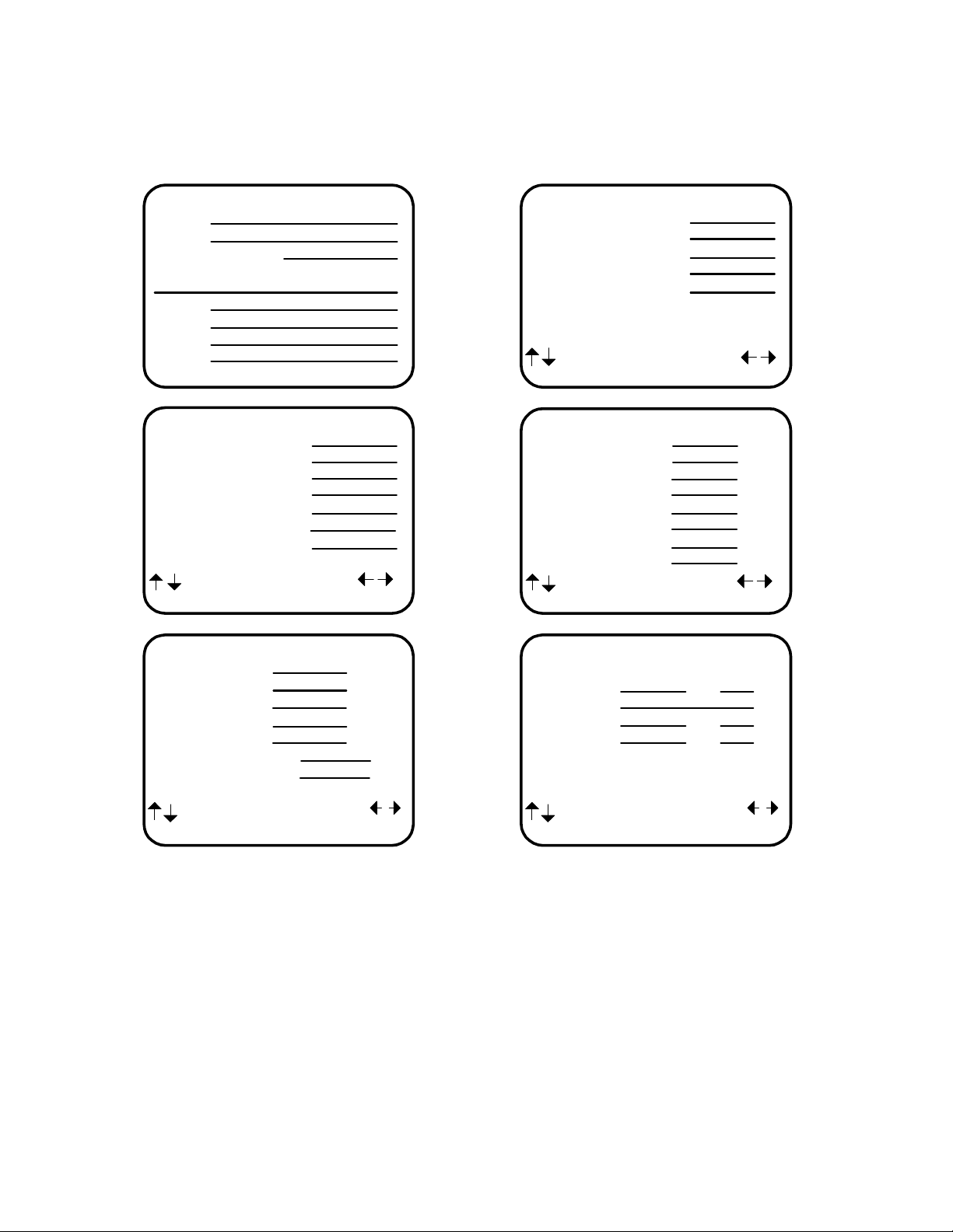
SETUP SPEAKER SIZE
1 Front
2 Center
3 Surround
4 Surround Back
5 Subwoofer
next item adjust
MENU setup speakers
SPEAKER LOCATION feet
1 Left Front
2 Center
3 Right Front
4 Right Surround
5 Right Surr Back
6 Left Surr Back
7 Left Surround
8 Subwoofer
next item adjust
MENU setup speakers
SETUP CROSSOVERS + LFE
1 Crossover Hz
2 High Pass dB
3 Low Pass dB
4 Peak Limiter dB
5 LFE Level dB
6 DTS LFE Mode
7 Subwoofer Phase
next item adjust
MENU setup speakers
SETUP SPEAKER LEVELS
1 Left Front dB
2 Center dB
3 Right Front dB
4 Right Surround dB
5 Right Surr Back dB
6 Left Surr Back dB
7 Left Surround dB
8 Subwoofer dB
next item adjust
MENU setup speakers
SETUP ROOM EQUALIZATION
Test Tone 20 Hz Off
Notch Hz dB
Notch Width Hz
Bass Hz dB
Treble Hz dB
next item adjust
MENU setup speakers
B&K Components, Ltd., 2100 Old Union Road, Buffalo New York 14227-2725
Phone (716) 656-0026, Fax (716) 656-1291, http://www.bkcomp.com, E-mail: info@bkcomp.com
p/n 12857 Rev. 0717A
Page 3

TABLE OF CONTENTS
Acknowledgments
Safety Precautions
Features
The Basics
Front panel
Rear Panel
Making the connection
........................................................................................
......................................................................................
......................................................................................
.....................................................................................
Audio / Video connections
Digital Connections
Surround Outputs
...............................................................................
..............................................................................
..........................................................................
.....................................................................
...........................................................................
............................................................................
Surround Speaker Output Connections
Antenna Connections
Control Outputs / IR Inputs
.........................................................................
.....................................................................
Frequently Asked Questions
Setup
Operation
..........................................................................................
The Menu System
System Setup
Speakers
Speaker Size
Speaker Location
Speaker Levels
Crossovers + LFE
Room Equalization
Display
Inputs
Presets
..................................................................................
...................................................................................
..................................................................................
Memory Backup
......................................................................................
Power On/Off
Sleep
.......................................................................................
Choosing a source
AM/FM Tuner
Adjusting the Volume
............................................................................
................................................................................
................................................................................
.........................................................................
.....................................................................
.......................................................................
.....................................................................
....................................................................
..............................................................................
................................................................................
...........................................................................
................................................................................
.........................................................................
Temporary Level Adjustments
Audio Modes
MONO
STEREO
SURROUND
THX
DVD Audio
Special Considerations
Equalization ‘EQ’
Zone ‘Z’
Presets
Zone 1 (A)
Zone 2 (B)
Zone 1 Favorite Presets
Zone 2 Favorite Presets
Getting Processor Status
Advanced Features
Advanced
Zone 1 Setup (A)
Zone 2 Setup (B)
Power On Titles
Control Outputs
................................................................................
..................................................................................
................................................................................
.............................................................................
....................................................................................
...............................................................................
....................................................................
.............................................................................
.....................................................................................
.....................................................................................
...................................................................................
...................................................................................
.......................................................................
.......................................................................
......................................................................
.............................................................................
................................................................................
......................................................................
......................................................................
.......................................................................
.......................................................................
Setup Control Out 1
Setup Control Out 2
..........................................................
...................................................................
..................................................................
...............................................................
................................................................
2
3
4
5
9
11
13
14
16
17
18
19
19
20
22
22
23
23
23
27
28
29
33
36
39
43
45
46
46
46
47
47
48
48
49
50
50
50
50
50
50
52
54
55
56
57
58
59
60
61
61
61
64
68
68
69
69
p/n 12857 Rev. 0717A
Page 4

Setup Control Out 3
Setup Control Out 4
Security Options
DSP Usage
......................................................................
..........................................................................
RS-232 Control Port
Factory Reset
Troubleshooting
A/V System Controller Specifications
Returning Equipment
Rear Panel Enlarged View
The Menu System
................................................................................
...............................................................................
...........................................................................
.......................................................................
...............................................................................
................................................................
................................................................
...................................................................
.............................................................
70
70
71
73
73
75
76
77
78
79
80
1
p/n 12857 Rev. 0717A
Page 5

ACKNOWLEDGMENTS
Motorola® ,, “ * DigitalDNA™, “Powered by Motorola”™, Motorola name and logo are registered trademarks
of Motorola, Inc.
Manufactured under license f rom Dolby Laboratories. “Dolby”, ”Pro Logic”, “AC-3", and the double-D symbol are
trademarks of Dolby Laboratories. Confidential Unpublished Works. © 1992-1997 Dolby Laboratories, Inc. All
rights reserved.
Surround EX is a trademark of Dolby Laboratories. Used under authorization.
®
DTS
is a registered trademark of Digital Theater Systems, LLC. Additionally licensed under the following US
Patent 5,451,942 & National Patent applications derived from PCT/US95/00959. Additional U.S. and Foreign
Patents pending. “DTS”, “digital sound” , and “coherent acoustic s” logos are tradem arks of DTS Technology LLC.
All rights reserved.
Manufactured under license from Lucasfilm Ltd. U.S. patent numbers 5,043,970; 5,189,703; and/or 5,222,059.
European patent number 0 323 830. Other U.S. and foreign patents pending. Lucasfilm and THX are registered
trademarks of Lucasfilm Ltd. Surround EX is a trademark of Dolby Laboratories. Used under authorization.
THX, Home THX Cinema, Lucasfilm THX, Re-Equalization, Timbre Matching, Adaptive Decorrelation and THX
Ultra are registered trademarks of Lucasfilm Ltd.
Accessories included:
Owners manual, Remote control Manual, Power cord, Remote control, 4-AAA batteries
© Copyright 2000 All Rights Reserved.
B&K Components, Ltd., 2100 Old Union Road, Buffalo New York 14227-2725
Phone (716)656-0026, Fax (716)656-1291, http://www.bkcomp.com, E-mail: info@bkcomp.com
2
p/n 12857 Rev. 0717A
Page 6

SAFETY PRECAUTIONS
PLEASE READ BEFORE INSTALLING
WARNING: to prevent f ire or shock hazard, do not expose this unit to rain or moisture. Care should be taken to
prevent objects or liquid from entering the enclosure. Never handle the power cord with wet hands.
The lightning flash with arrowhead, within an equilateral triangle, is intended to alert the user of the presence of
uninsulated “dangerous voltage
The exclamation point within an equilateral triangle is intended to alert the user of the presence of important
operating and maintenance (servicing) instructions in the literature accompanying the unit.
Caution: To prevent the risk of electric shock, do not remove cover. No user-serviceable
servicing to qualified service personnel.
If an outdoor antenna is connected to the antenna input, be sure it is grounded to provide som e protection agains t
voltage surges and built up static charges. Keep the outdoor antenna away from power lines.
Unplug the processor from the AC outlet when plugging in or unplugging cables, when left unused for an extended
period of time, moving the processor, or when you suspect lightning in your area.
Prevent damage to the power cord. Do not bend, pull, place objects on, alter, etc. Replace the power cord if it
becomes damaged. Always grasp the plug on the power cord when plugging in or unplugging the proces sor from
the AC outlet.
Your system may produce sound levels capable of causing perm anent hearing los s. Do not operate f or extended
periods of time at high volume levels.
Make sure the processor is placed on a level surface.
Protect the processor from impact. (Do not drop it!!!)
Do not climb on top of the processor or place heavy objects on its top cover.
The processor is equipped with raised feet to provide ventilation, reduce acoustic feedback, and provide protection
against scratching the surface the unit is resting on. We advise against removing or altering feet.
Do not stack anything on top of the proc es sor ( proc es sor , s ourc e, etc .) Leave a minimum of 3” c learanc e f rom the
top of the processor to the next shelf (or component).
The processor should be located away from heat sources such as heaters or amplifiers.
Do not perform any internal modifications to the processor.
Always connect the processor’s power cord to an unswitched AC outlet for normal operation.
If young children are present, adult supervision should be provided until the children are capable of following all
rules for safe operation.
Do not plug the processor’s power cord into an outlet with an unreasonable number of other devices . Be careful if
using extension cords and ensure the total power used by all devices does not exceed the power rating
(watts/amperes) of the extens ion cord. Exc ess ive loads m ay cause the ins ulation on the c ord to heat and pos sibly
melt.
Mistaking
processor or other components.
Damage can occur to your speak ers if the power rating of each individual driver is exceeded by the amplif iers
connected to your processor. Ensure that all the drivers in your system are capable of handling not only the
average power being delivered by the amplifiers, but also the peak power that is likely to be generated during
strong passages.
where you purchased them.
The processor should be serviced by qualified personnel when:
CONTROL OUTPUT
If you are unsure of your speaker's power rating, contact the speaker manufacturer or the dealer
The processor is not functioning properly.
Objects have entered the chassis.
The processor was exposed to rain or other type of moisture.
The processor was dropped, or the chassis is damaged.
” within the product’s enclosure that may constitute a risk of electric shock to you.
parts inside. Refer
IR INPUT
or
connectors for audio/video inputs or outputs may damage your
3
p/n 12857 Rev. 0717A
Page 7

FEATURES
Your new processor is a versatile audio/video control center. The processor is designed to sound sensational and be an
attractive, easy-to-use addition to your audio/video system. Although you already have a good idea of your processor’s
features, we would like to take a moment to point out certain highlights.
THX Ultra Certified -
to correct for the tonal and spatial errors that occur during the translation from the movie theater environment into the home.
In addition to the these correction processes, the unit has passed a rigorous series of Lucasfilm THX quality and performance
tests which is your guarantee that this Home Theater product will give superb performance for years to come.
THX Surround EX -
Surround EX signals.
Two-zone operation
preamp internally for use with a second listening/viewing area - Zone 2 (B).
Internal Digitally Synthesized AM/FM Stereo tuner
Analog inputs/outputs
set of 7.1 surround outputs.
Component Video
allows full pass through of HDTV signals and maintains full signal integrity.
Digital inputs/outputs
Control Outputs
projection screen or B & K amplifier.
IR inputs/outputs
system.
Gold Plated Connectors -
incorporates Lucasfilm Home THX Re-Equalization™, Timbre Matching™ and Adaptive Decorrelation™
incorporates further Home THX Cinema processing to allow for the precise decoding of Dolby Digital
- complete digital/analog preamp/processor for Zone 1 (A) plus an additional independent analog A/V
- store up to 40 AM or FM stations in A/V presets.
- seven A/V inputs and five A/V outputs
- two switchable inputs and one set of outputs assignable to any of the seven A/V inputs. Passive design
- six coaxial inputs and one coaxial output plus five optical inputs and one optical output.
- four 12 VDC @ 50 mA outputs for turning on amplifiers and controlling external systems such as a
- two IR inputs and up to four IR outputs let you integrate the processor with an infrared repeater control
better sound with minimum signal loss and degradation.
all
with stereo audio, composite video and S-video plus one
Plug and Play operation
automated functions to provide invisible and easy operation.
A/V presets
Customized input and A/V preset names
Front Panel Operation
Remote Control
of B&K and other brand user equipment.
RS-232 Control
96/24 bit A/D and D/A Conversion
96/24 bit processing
listening modes.
Selectable Bass Management Crossover Frequency and Slope
management to assure optimum performance from your speaker system.
Room Equalization
the best possible room response.
Upgradable
art today, state of the art tomorrow.
- 40 preset memories allow instant system configuration recall of user settings.
- 8 device universal remote control, 100% pre-programmed, 100% learning, provides easy and total control
- easy control and interface of your B&K product with other system controllers.
- modular design allows for future A/D, D/A, DSP, Digital Receiver, and IEEE 1394 enhancements. State of the
- automatically selects the optimum input, surround sound format, and performs a wide range of
- assign names to presets, inputs, or the turn on message.
- nearly all processor functions can be controlled directly from the front panel.
- Ultra High Resolution reproduction of musical details.
- 96/24 bit digital data and analog source material use 96 kHz, 24 bit DSP processing during all stereo
- allows system versatility for bass adjustments and
- a sweepable notch filter and variable equalization is available in the digital domain for use in achieving
4
p/n 12857 Rev. 0717A
Page 8
THE BASICS
The following is intended to familiarize users with common terms and applications of Home Theater equipment.
Sources -
from its on-sc reen menu system. Typically you will want to connect a number of additional sources ( VCR, DVD
player, etc.) to your processor. Your processor is designed to accommodate a wide range of audio and video
signals.
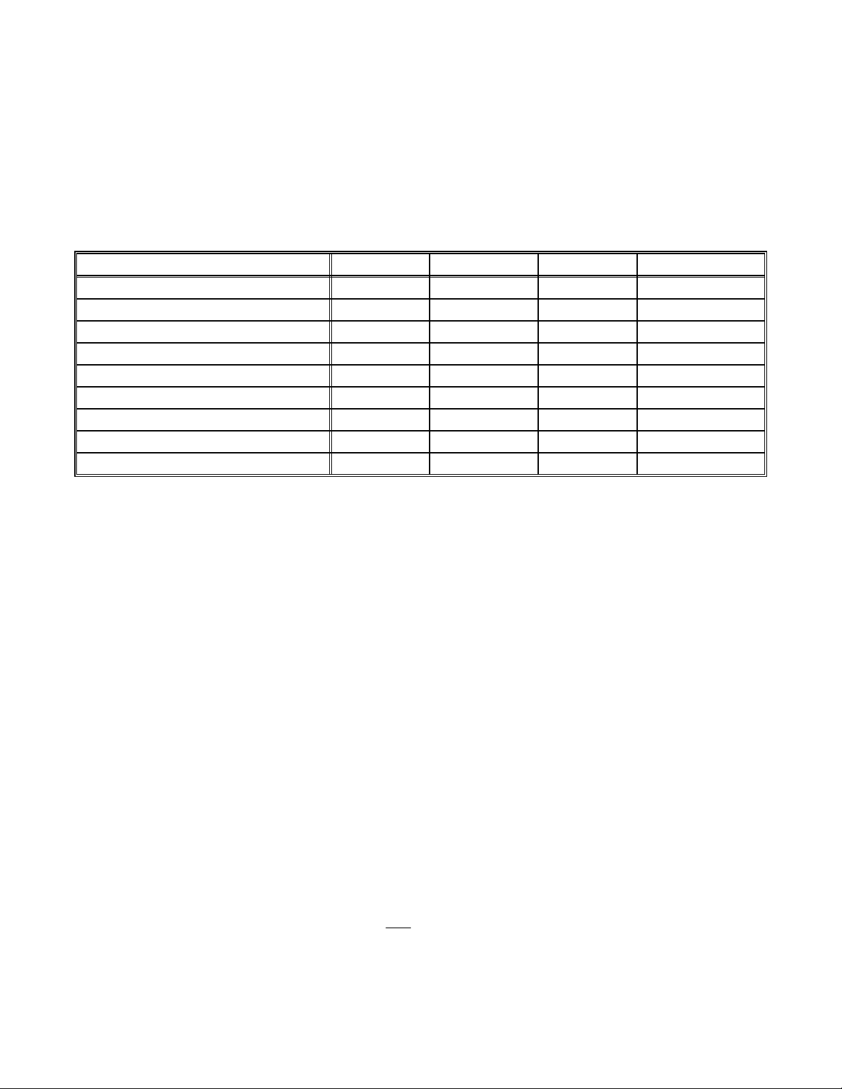
The following table lists the most popular home theater media and how the audio information is stored.
Analog vs. Digital Audio -
how they are delivered to your processor from the source. Analog signals exactly represent the sound you will hear
through a continuously varying voltage. Audio and video cassettes are analog recordings and are normally
delivered to your processor over a pair of coaxial audio cables.
Digital signals closely approximate the original audio signals with a set of numbers referred to as a bitstream . CDs
and DVDs are sources of digital audio and are norm ally connected to your processor through a coaxial or optical
digital cable. There are several different bitstream formats available. The simplest form at is called Pulse Code
Modulation (PCM). In PCM, the bitstream directly represents the original 2-channel audio. In Dolby Digital and
DTS (see “Surround Formats” below) bitstreams are modified using a process called compression to squeeze
more information into limited space. DTS squeezes 5.1 channels into the space normally required for two
uncompressed channels, while Dolby Digital squeezes 5.1 channels into about ¼ the space required for two
channels. Your processor automatically detects the bitstream currently being provided from the source and
performs the requir ed decompression and s urround processing. If no digital signal is present your processor will
automatically switch to analog processing.
your processor can directly provide audio from its built-in AM/FM tuner. It can also provide limited video
DTSDolby DigitalPCMAnalogSource Media
XAudio Cassette
XVideo Cassette
XXXXLaser disc (LD)
XXXCompact Disc (CD)
XXXDigital Versatile Disc (DVD)
XXSatellite Broadcast
XXXXDigital Audio Tape (DAT)
X (compressed)Digital Compact Cassette (DCC)
X (compressed)Mini disc (MD)
This refers to the m ethod used to place audio inform ation on the source m aterial and
All sounds that you hear from your speakers are analog. Digital s ignals are automatically converted to analog by
your processor before being output to your the speakers.
If analog signals exactly represent the audio, while digital signals only approximate it, why would I want to
use digital?
All analog sources add some amount of noise and distortion to the audio signal. Additional noise can be
picked up through the cables from the sourc e to your processor. It is im possible for the process or to tell
the difference between the desired signal and the added noise and distortion, so it reproduces both of
them. The result is inc reased back ground noise and decreased dynamic range and f idelity. Digital signals
are virtually immune to noise and distor tion. The processor can, therefor e, reproduce the signal with the
greatest possible fidelity. We recommend you use digital signals wherever possible. Also Dolby Digital and
DTS (see “Surround Formats” below) work only
Audio and Surround Formats
Monaural (Mono)
Modern recordings are seldom m ade in this for m at, but mos t older m ovies and m usic ar e available only in
this format. You m ay get mono from any source - digital or analog. Sound will norm ally come from the
- This is the oldest format available. It contains a single, full range audio channel.
- Your source material will be in one of seven possible formats described below.
with digital signals.
5
p/n 12857 Rev. 0717A
Page 9

seven speaker channels, but your processor can produce m ono in one to seven channels (see “Audio
Modes under Operation”). Since all modern sources are stereo, the mono information is usually replicated
from both the left and right channels.
Stereo - Stereo contains two discrete, front left and right full range audio channels. This is the most
common f orm at f or mus ic and is als o used on m any movies. You may get stereo from any source - digital
or analog. Sound will normally come f rom the seven speaker channels, but your processor can produc e
stereo in one (mono) to seven channels (see “Audio Modes under Operation”).
Dolby Pro Logic - Dolby Pro Logic is a refinement of Dolby Surround which was the earliest form of true
surround processing. Like Stereo, Dolby Surround contains two discrete, full range audio channels. In
addition, a monaural, lim ited range surr ound channel is encoded on the two s tereo channels in a proces s
called matrixing. T he surround channel inform ation is encoded in positive polarity on the left channel and
in negative polarity on the right channel. The Dolby Processor can detect this encoding (left minus right)
and send that information to the surround channels. Dolby Pro Logic adds additional processing to
produce a full range center channel by extracting the mono inf ormation from the left and right channel.
This is the most common format for all but the most recent movies. Music sources are occasionally
encoded in Dolby Surround. However, many people prefer to use Pro Logic processing on all of their
stereo sources. The c enter channel extraction process often yields improved stereo imaging, es pecially
when you are sitting away from the “sweet spot” at center of the listening area. The surround channel
processing often lends a pleasing ambiance even to m ater ial that is not encoded in Dolby Surround. Dolby
Pro Logic is fully compatible with stereo and you may get it from any source - digital or analog. Sound will
normally come from all seven speakers in your system, but your processor can produce sound in one
(mono) to seven channels (see “Audio Modes under Operation”).
Dolby Digital - Dolby Digital contains up to five discrete, full range audio channels plus an additional Low
Frequency Effects (LFE) channel. T he LFE channel contains only low frequency information f or enhanced
sound effects in movies . This combination of five discrete c hannels plus a LFE channel is of ten ref err ed to
as 5.1 channels. Dolby Digital is a digital form at only. It m us t be deliver ed to your proces s or over a c oax ial
or optical digital cable. As of the writing of this manual, Dolby Digital is commerc ially available on DVD and
Satellite (Also see
DATs if you have the recording equipment. You can’t direc tly record Dolby Digital onto mini disc or digital
compact cassette since these devices add their own compression which is incompatible with the Dolby
Digital compression. Not all Dolby Digital recordings will include all five channels, and, in fact, it is
common on DVDs to have two channel Dolby Digital with or without Pro Logic processing. Sound will
normally come from all seven speakers in your system, but your processor can produce sound in one
(mono) to seven channels (see “Audio Modes under Operation”).
Dolby Digital RF
below). It is also possible to create your own Dolby Digital CDs and
Dolby Digital RF - Dolby Digital RF is identical to normal Dolby Digital except that it uses a special RF
encoding scheme to put the bitstream on Laser discs without replacing the normal stereo (or Dolby
Surround) PCM bitstream that is norm ally available from laser disc. In order to use Dolby Digital RF laser
discs you must have a B&K DT-1 RF demodulator or sim ilar product f rom another m anuf acturer. For best
results with your processors Plug and Play capability we recommend the B&K DT-1.
Dolby Digital Surround EX - Dolby Digital Surround EX is a new movie sound track that greatly
enhances the sense of spatial and positioning of the s ur round c hannel s ound. This system was developed
jointly by Lucasfilm THX and Dolby Laboratories, using Lucas film ’s idea of improving spatial expres sion
and achieving a 360 degree sound positioning with Dolby Laboratories’ matrix encoding technology. The
surround back channel is matrix-encoded and inserted into both Dolby Digital SL (surround lef t) and Dolby
Digital SR (surround right) channels. Upon playback, the signals may be decoded by a high precision
digital matrix decoder within the Dolby Digital decoder into SL, SR and SB channels.
DTS (Digital Theater Systems) - DTS is similar to Dolby Digital in that it provides 5.1 discrete audio
channels. However, it uses m ore digital data to encode the information and may provide greater fidelity
than Dolby Digital. DTS is a digital format only. It mus t be delivered to your processor over a coaxial or
optical digital cable. No RF demodulator is required for DTS laser discs since the DTS bitstream replaces
the normal PCM bitstream. Like Dolby Digital,
6
p/n 12857 Rev. 0717A
Page 10

you can create your own DTS DATs or CDs but not mini disc or digital compact cas sette. As with Dolby
Digital, sound will normally come from all seven s peak ers in your system, but your processor can produc e
sound in one (mono) to seven channels (see “Audio Modes under Operation”).
DVD Audio (also referred to as MLP) - Meridian Lossless Pack ing ( MLP) is a los s less c oding s ystem f or
high-quality linear PCM audio. For DVD-Audio MLP perform s lossless c om press ion of up to 6 c hannels of
up to 24-bit material sam pled at rates between 44.1kHz and 192k Hz. Lossless coding does not alter the
final signal, it ‘packs’ the audio data into a smaller rate and space. Currently, DVD Audio can only be
delivered to your processor via the analog 5.1 input. Sound will normally come f rom all seven speak ers in
your system, but your processor can produce sound in one (mono) to seven channels ( see “Audio Modes
under Operation”).
Home THX Cinema Processing - THX is an exclusive set of standards and technologies established by
the world-renowned film production company, Lucasfilm Ltd. THX grew from George Lucas’ personal
desire to mak e your experience of the film soundtr ack , in both m ovie and in your home theater, as f aithful
as possible to whatever the director intended.
Movie soundtracks are mixed in special movie theaters called dubbing stages and are designed to be
played back in movie theaters using similar equipm ent and conditions. The soundtrack c reated for movie
theaters is then directly put onto reproducible media, DVD, VHS tape Laser disc, etc... With no changes to
account for playback in a smaller home theater environment.
THX engineers developed patented technologies to accurately translate the sound from the m ovie theater
environment into the home, correcting for the tonal and spatial errors that occur. While Home THX
Cinema mode is active, T HX proces s ing is added after the Dolby Pro Logic, Dolby Digital or DTS decoder.
Sound will normally come from all seven speaker s in your system, but your processor can produce sound
in one (mono) to seven channels (see “Mode Operation”).
Re-Equalization™ - restores the correct tonal balanc e for watching a movie soundtrack in a small hom e
theater.
Timbre Matching™ - filters the information going to the surround speakers so that they more closely
match the tonal characteristics of the sound coming from the front speakers. This ensures seamless
panning from the front to surround speakers.
Adaptive Decorrelation™ - slightly changes one surround channel’s time and phase relationship with
respect to the other surround channel. This expands the listening position and creates a more spatial
sense using only two speakers.
THX Surround EX – Dolby Digital Surround EX is a joint developm ent of Dolby Laboratories and the TH X
division of Lucasfilm Ltd.
In a movie theater, film soundtr acks that have been encoded with Dolby Digital Surround EX technology
are able to reproduce an extra channel which has been added during the mixing of the program. This
channel, called Surround Back, places sounds behind the listener in addition to the currently available
front left, front center, f ront right, surround right, surround left and subwoofer channels. This additional
channel provides the opportunity for more detailed imaging behind the listener and brings more depth,
spacious ambiance and sound localization than ever before.
When releas ed to the home c onsum er m ark et, m ovies that were created us ing the Dolby Digital Surround
EX technology, may have a note to that effect on the packaging. A list of movies created using this
technology can be found on the Dolby web site at http://www.dolby.com.
Only receiver and controller products bear ing the THX Surround EX logo, when in the THX Sur round EX
mode, faithfully reproduce this new technology in the home.
This product m ay also engage the “THX Sur round EX” m ode during the playback of 5.1 channel m aterial
not
that is
Back channel will be program dependent and may or may not be very pleasing depending on the
particular soundtrack and the tastes of the individual listener.
Dolby Digital Surround EX encoded. In such case the inf ormation delivered to the Surround
7
p/n 12857 Rev. 0717A
Page 11

Bass Management - Dolby Digital and DTS formats contain up to 5 full range channels plus LFE. Only a system
with five full-range (large) speak ers plus a subwoofer can directly reproduce these f ormats. However, almost all
commercially available center channel speakers are small and incapable of reproducing the lowest bass
frequencies without distortion or even dam age to the speak er. Many people also use sm all speak ers in the rear of
their system, while others use sm all s peakers all around. Use of a s ubwoofer is almost mandatory when using five
small speakers , but people with at least two large speakers may or may not choose to use a subwoofer . Some
people may not use a center channel or surround speak ers at all. In order to handle any possible combination of
large, small, or m issing speak ers, a hom e theater system must contain good bass m anagement, a concept often
missing from two-piece systems where the Dolby Digital or DTS decoder is separate from the preamp. Your
processor contains a c omplete bass management system. You can use as few as two large fr ont left and right
speakers or two sm all left and right speakers plus a subwoofer or as m any as seven full range speakers plus a
subwoofer or any combination in between without miss ing any information. Wher ever s mall speakers are used the
bass management system prevents low bass information from going to that speaker (“high pass”). This bass
information is rerouted to a speak er that can handle it, usually a subwoofer, but it can also send center, surr ound,
or LFE bass to large front speakers if no s ubwoofer is available. W hen center or surround s peakers are not used
at all, the missing channel is sent (“down mixed”) to the front speakers.
Preamp - A preamp typically includes the capability to select from a num ber of s ources, adj ust volum e levels and
route the data to an amplifier. Your processor includes a high quality preamp.
Processor - A processor typically includes the capability to decode one or more surround form ats, and convert
between digital and analog as required. Your A/V system controller includes a high quality processor capable of
decoding the surround formats described above.
Zone - A zone is usually a room that has speak ers ins talled in it. Your proces sor includes a full pr eam p/proces sor
for Zone 1 (A) plus an additional analog stereo pr eam p for Zone 2 (B) . This allows, for ex am ple, watching a Dolby
Digital movie in zone one while simultaneously using the built-in AM/FM tuner in another room.
Amplifier - An amplifier takes the output of a preamp/processor and increases its level to that necessary to drive a
speaker.
Speakers - A surround sound system use to typically use 5 speakers loc ated left front, center front, right f ront,
right surround, and left surr ound plus a subwoofer located anywhere in the room. W ith the new developm ents in
surround technology from companies such as Dolby Laboratories, DTS, and Lucasfilm, it is now possible to
improve spatial expres sions with an additional channel of inf ormation for use with a 6th and/or 7th s urround back
speaker. Although best results are achieved using seven large speakers plus a subwoofer, this is not always
practical. Excellent results can be achieved us ing sm all and/or fewer speak ers, as long as you go through the set
up procedures described later in the manual. Your processor includes the capability of reproducing up to 6.1
channels of surround information.
Component video vs. S-video vs. Composite video - Composite video is the oldest standard for color video. It
combines the luminance (brightness or black-and-white) and chrominance (color) information onto a single
conductor. These signals m ust be separated again for display resulting in som e degradation of the video quality.
S-video is a newer standard that uses separate conductors for the lum inance ( Y) and chrom inanc e (C) inf or mation
resulting in better video quality. Component video is the newest form of video introduced with DVD. This video
format uses separate conductors for luminance (Y), red - luminance ( R - Y), and blue - lum inance (B - Y). Using
these signals a component video capable monitor allows for even better and higher resolution video quality. Your
processor is capable of s witching com posite, S- video and com ponent signals, but it c annot convert between video
types. In addition, your processor is capable of switching between two pairs of component video inputs.
8
p/n 12857 Rev. 0717A
Page 12
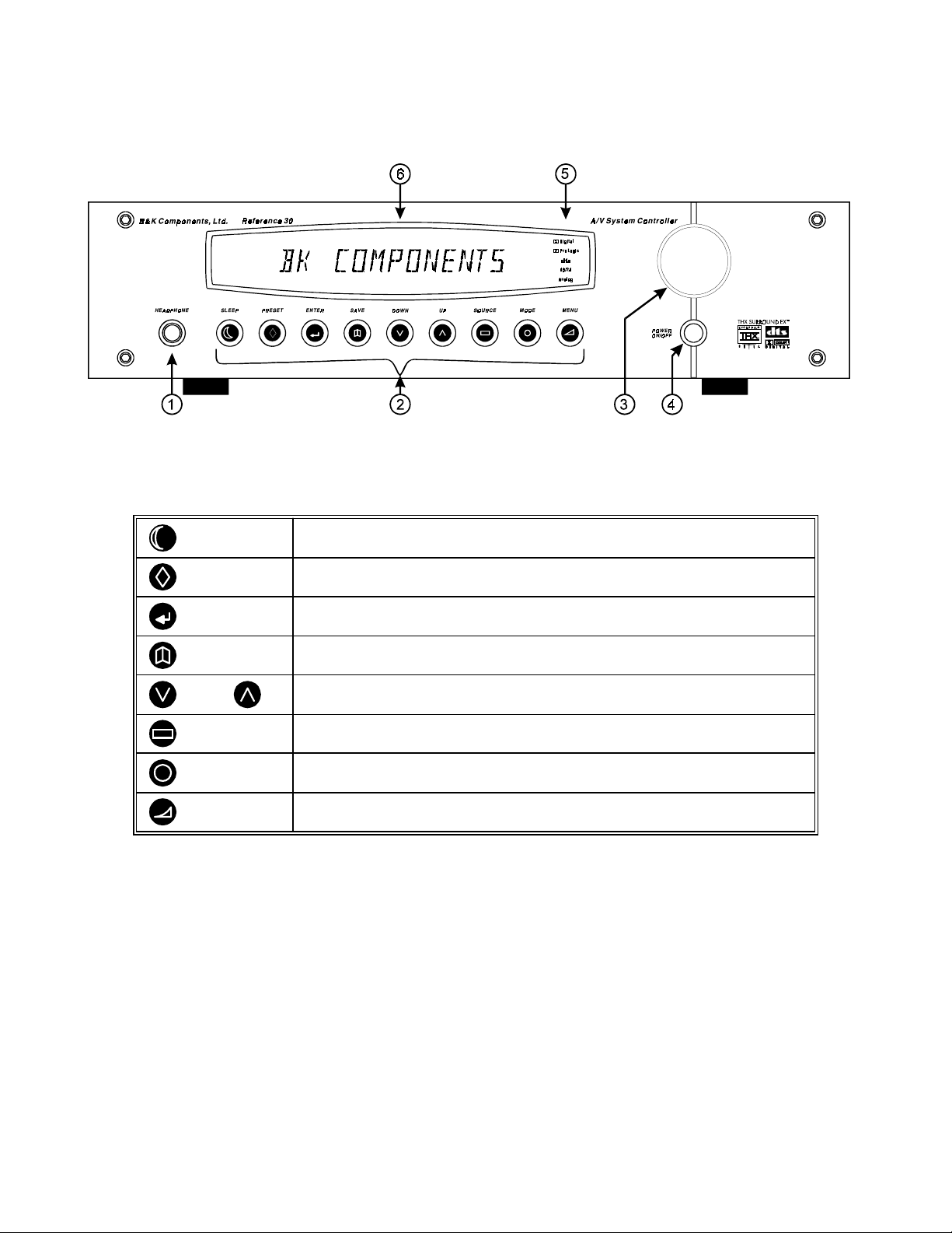
FRONT PANEL
1. Headphone Jack
- Stereo headphones having a standard ¼ inch binaural plug can be connected to the
headphone output. The processor must be on and in HEADPHONE Mode for proper headphone operation.
2. Front panel buttons
SLEEP
PRESET
ENTER
SAVE
DOWN UP
SOURCE
MODE
MENU
3. Main power switch
- Removes all power to the processor. Norm al operation of the processor requires the
Puts the receiver in standby (low power) mode.
Steps through audio / video presets for instant recall of setups.
Pressing ENTER recalls the preset.
Confirm selection or display current status of the receiver.
Pressing SAVE followed by ENTER saves a favorite preset.
Step through menus, sources, or audio modes.
Steps through the audio / video sources.
Steps through the audio modes.
Enter / exit menu system
power switch to remain on. Use the Sleep button f or daily on and off of the proces sor. It places the unit in standby
mode that allows turning back on with the remote control. Turn the pr ocess or off with the main power switch when
not using the processor for an extended period of time.
4. Volume control
- For controlling system volume. Turn ing the encoder-type volume control cloc kwise increas es
the volume level, countercloc kwise decreases the volume level. The volume knob is also used to change other
processor settings. See THE MENU SYSTEM and OPERATION
9
p/n 12857 Rev. 0717A
Page 13

5. Status indicators - Displays current status of the processors audio processor. Indicators have been supplied to
show when the DSP is decoding Dolby Digital ‘ Digital’, Dolby Pro Logic ‘ Pro Logic’, or DTS audio. There is
an indicator to show the input to the S/PDIF digital receiver is 96k Hz 24 bit data ‘96/24’ or an analog input that is
being sampled using 96kHz/24bits. Finally, there is an indicator to show processed audio is sourced from the
selected analog input ‘Analog’. See MODE OPERATION
6. Display - The processor display is a 16 character alphanum eric fluorescent dis play. Displays current status of
processor and any changes being performed.
10
p/n 12857 Rev. 0717A
Page 14
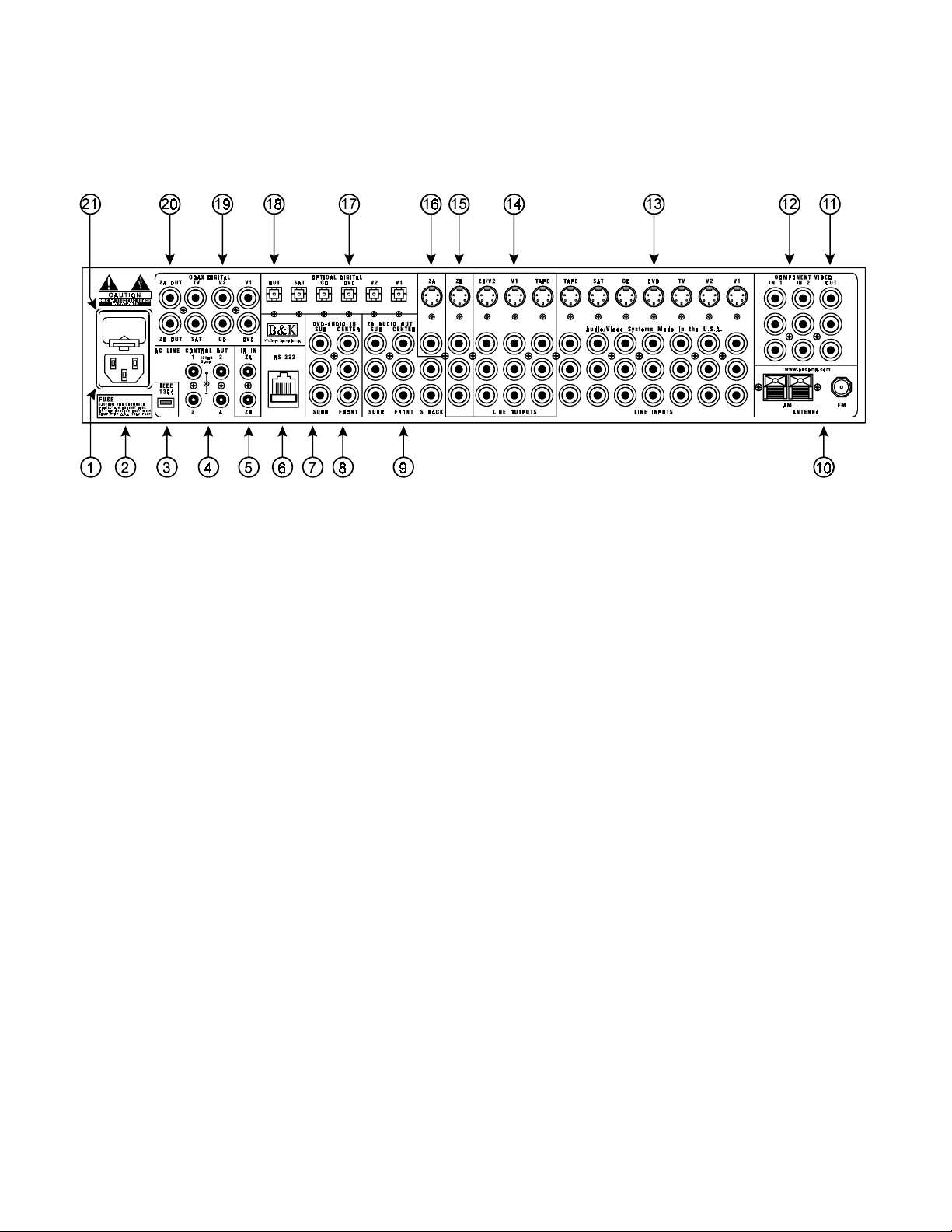
REAR PANEL
The processor’s back panel is organized into groups of inputs and outputs f or audio and video as shown below.
See back of this manual for an enlarged view.
1. AC input receptacle
2. AC Line Voltage -
3. IEEE 1394 input (optional) -
4. Control outs
5. IR in
processor. This m ethod of control is useful when the front IR receptor is bloc ked (for ex ample, by a cabinet door)
or to control the processor from another room. This input is typically used in place of an emitter attached to the
front panel.
6. RS-232 input -
7. Serial number -
8. DVD Audio inputs
9. Surround outputs
10. Antenna inputs -
11. Component Video outputs
- Accepts input from external IR receptor s . Connect an IR repeater (“home run”) to IR IN for controlling the
Red RCA jacks
White RCA jacks
Gray RCA jacks
Red RCA jack
Green RCA jack
Blue RCA jack
- Outputs that allow you to remotely control external devices. (See “Making The Connection“).
- For attaching the supplied AC power cord to the processor.
Indicates the proper voltage and frequency needed to operate your processor.
For future interface applications.
Computer interface applications.
The serial number of your unit is located on bottom of unit
- Connections for a DVD audio or other 5.1 source device.
- right front and surround audio inputs
- left front and surround audio inputs
- center and sub audio inputs
- Variable level outputs for driving external power amplifiers or powered speakers.
Connections for the AM and FM antennas.
- Switched output connections for your component video monitor.
- typically connect to the red input on a component video monitor
- typically connect to the green input on a component video monitor
- typically connect to the blue input on a component video monitor
11
p/n 12857 Rev. 0717A
Page 15

12. Component Video inputs - Switched input connections for two component video devices.
12. Component Video inputs - Switched input connections for two component video devices.
Red RCA jack
Green RCA jack
Blue RCA jack
13. Line inputs - Connections from your audio/video sources.
Red RCA jacks
- right analog audio
White RCA jacks
Yellow RCA jacks
4 pin din jacks
14. Line level outputs - Fixed level outputs to an audio or video recorder.
15. Zone 2 (B) outputs - Variable level outputs to your video monitors and external amplifiers.
16. Zone 1 (A) outputs - Variable level outputs to your video monitors.
17. Optical Digital inputs - Optical digital inputs are used to c onnect digital audio signals f rom your source to the
processor. The incoming signal may be PCM, Dolby Digital or DTS.
18. Optical Digital output - Zone 1 (A) optical output to carry digital information from the select ed digital input of
the processor out to digital recorders, personal computers, etc.
19. Coax Digital inputs - Coax digital inputs are used to connect digital audio signals from your source to the
processor. The incoming signal may be PCM, Dolby Digital (AC-3) or DTS.
20. Coax Digital output - Independent Zone 1 (A), and Zone 2 (B), coax outputs to carry digital information fr om
the selected digital input of the processor out to digital recorders, personal computers, etc.
21. AC fuse holder - Holds the AC Line fuse. Replace only with same type and value.
- typically connect to the red output of a component video source
- typically connect to the green output of a component video source
- typically connect to the blue output of a component video source
- left analog audio
- composite video
- S-video
12
p/n 12857 Rev. 0717A
Page 16

MAKING THE CONNECTION
It’s tempting to just plug in your new A/V processor and have great sound pour out. Bef ore you do that, take a few
minutes to plan out how you want the processor to fit into your audio/video system. Ask yourself the following
questions:
y
What source components do I want to connect to my processor? (CD, VCR, etc.)
y
What equipment will be receiving the audio and video? (TV monitor, Speakers, etc.)
The answers to your questions determine how many cables you need to connect to the back of the proces sor.
Good preplanning equals great sound. Keep these recommendations in mind:
y
List all components in your system and indicate which jacks of the processor each component will be
connected to. Your processor has seven sets of inputs. It is convenient to c onnect a DVD player to the input
labeled DVD or a VCR to the input labeled V1 or TAPE, etc. However, your equipment may differ from the
labeling on the back of your processor. In most cas es you can connect any type of source to any input (see
FREQUENTLY ASKED QUESTIONS) . For example, if you don’t have a satellite receiver you can connect a
DAT player or a second cassette deck to SAT. You can also reprogram the source nam e that will appear on
your processor’s front panel and on-screen display (see SYSTEM SETUP - INPUTS)
y
Also note the length of the cable for each component’s connec tion and describe how it should be routed or
draw your routing scheme below your list. You may want to label each cable with a name or number at both
ends. Use high quality connections to maintain high quality audio and video.
y
Think about the type and length of cable you need and obstacles in the cable’s path (doorways, furniture,
walkways, e tc.). To dec ide which ones are right for you talk to your dealer about the various cable products
that are available.
y
For safety, keep all cables out of high traffic areas (hallways or doorways) and away from equipment that
radiates power, including amplifiers, power cords, heaters, etc.
y
If you might expand your audio/video system later, keep these ideas in mind as you plan current cable runs.
y
To provide the best tuner reception, m ake sure the antenna is at least s everal feet away from the process or
and any other equipment that may produce high frequency interference such as Personal computers, CD
players, halogen lamps, etc.
Take a look at the back panel of the processor. You will notice that the RCA-type audio input and output
connectors are identified by colors, red f or right channel and white for the left channel audio. Component video
input and output connectors are identified by Red/Green/Blue. Composite video input and output connectors ar e
identified by yellow. Coaxial digital inputs are identified by orange. The surround outputs are identified by
Red/White/Grey.
13
p/n 12857 Rev. 0717A
Page 17
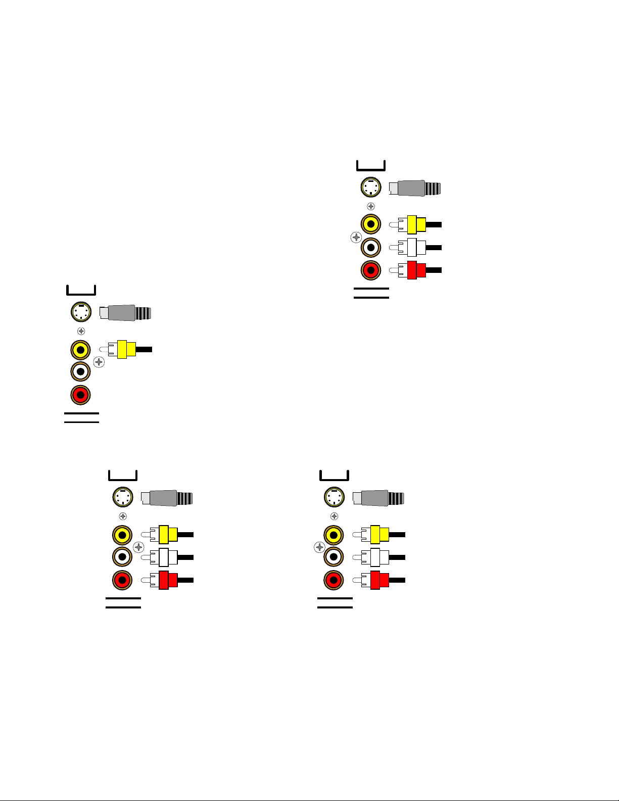
AUDIO / VIDEO CONNECTIONS
Connecting your analog sources to your processor
Audio / Video source -
connecting a DVD/VLD player to the processor’s analog inputs. Use the same instructions
for connecting to other audio / video sources such as a television, satellite receiver, cable box, etc. See
Connecting Video for use with other than com posite and S-video (Omit the video connections f or an audio-only
component such as a CD player)
DVD
Attach one end of the audio interconnect cable to the left audio
output on the DVD/VLD player, then attach the other end to the
S-Video input
from DVD output
left (white) DVD/VLD audio input on the processor. Repeat for
the right (red) audio connection. Attach one end of the
composite video interconnect cable to the video out on the
DVD/VLD player, then attach the other end to the yellow video
input on the processor labeled DVD/VLD. Repeat for the
S-video connections if you are using S-video.
Composite video input
from DVD output
Left audio input from
DVD output
Right audio input from
DVD output
ZA
LINE INPUTS
S-Video output
to monitor input
Composite video output
to monitor input
Video Monitor -
interconnect cable to the video input on the monitor, then attach
the other end to the yellow video output on the processor’s
Attach one end of the composite video
ZONE OUTPUTS. Repeat for the S-video connections if you
are using S-video. Dual zone operation requires connections be
made to (ZA) for Zone 1, and (ZB) for Zone 2.
S BACK
VCR or audio recorder -
connect a VCR to V1 . Use the same
instructions for c onnecting to the V2 and T APE analog inputs . If
connecting a cassette deck or other audio-only recorder then omit the video connections.
V1
S-Video output
to VCR input
Composite video output
to VCR input
Left audio output
to VCR input
Right audio output
to VCR input
LINE OUTPUTS
V1
S-Video input
from VCR output
Composite video input
from VCR output
Left audio input
from VCR output
Right audio input
from VCR output
LINE INPUTS
Attach one end of the audio interconnect cable to the left audio output on the VCR, then attach the other end to the
left (white) V1 audio input on the processor. Repeat for the right (red) audio connection. Attach one end of the
composite video interc onnect cable to the composite video output on the VCR, then attach the other end to the
yellow video input on the processor labeled V1. Repeat for the S-video connections if you are using S-video.
Attach one end of the audio interconnec t cable to the left audio input on the VCR, then attach the other end to the
left (white) V1 audio output on the processor. Repeat for the right (red) audio connection. Attach one end of the
composite video interconnect cable to the composite video input on the VCR, then attach the other end to the
yellow video output on the processor labeled V1. Repeat for the S-video connections if you are using S-video.
14
p/n 12857 Rev. 0717A
Page 18
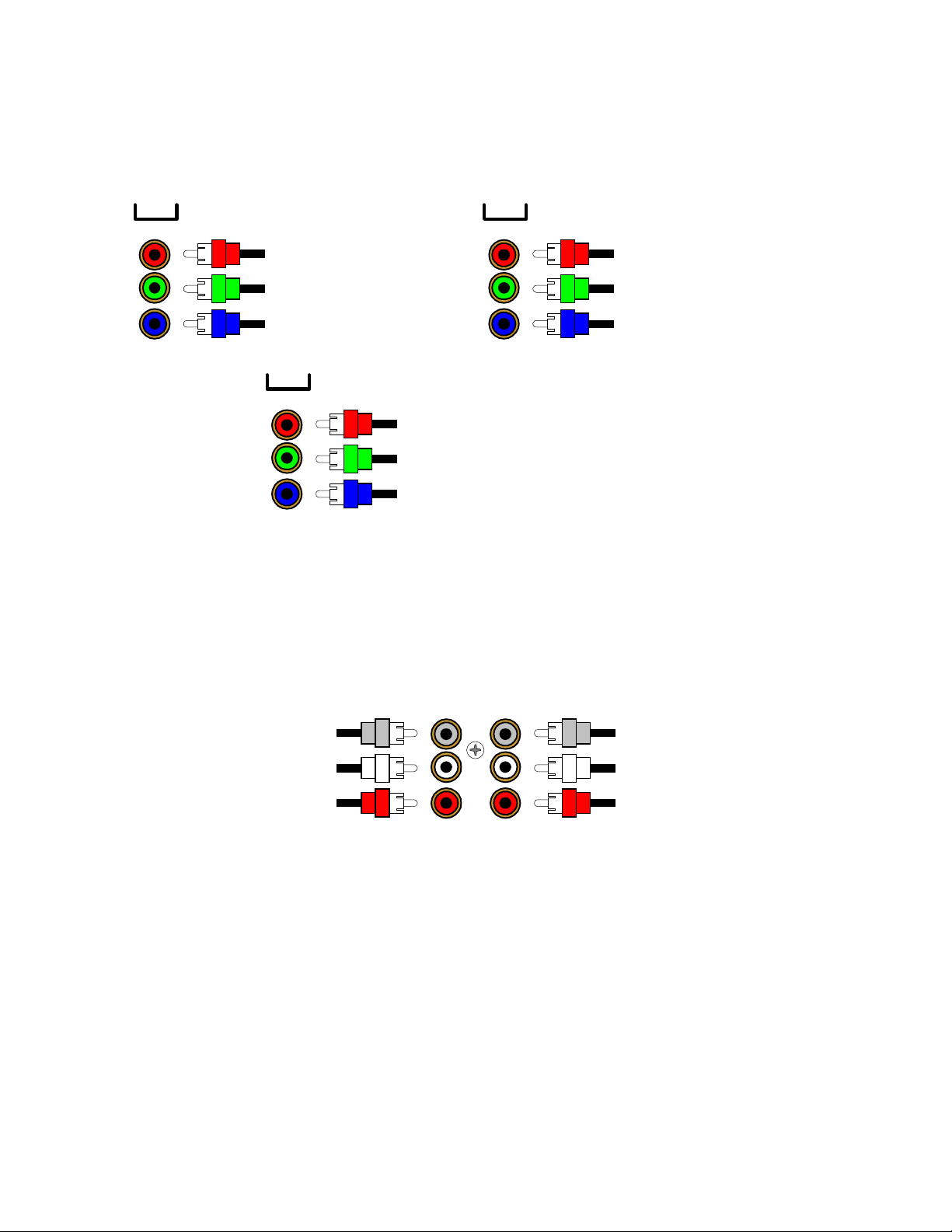
Component Video - in addition to S-video and composite video s witching, your processor provides two sets of
g
g
g
g
g
component video inputs for DVD and TV/DBS type inputs, and one set of component video outputs. Your
processors component video connection are passive to minimize the possibility of video format compatibility
issues. Use the same instructions to connect a second (TV/DBS) component video device.
COMPONENT VIDEO
IN 1
Component video input to DVD
red output
Component video input to DVD
reen output
Component video input to DVD
blue output
OUT
Component video output to the
video monitor's red input
Component video output to the
video monitor's
Component video output to the
video monitor's blue input
IN 2
Component video input to V1
red output
Component video input to V1
reen output
Component video input to V1
blue output
reen input
Attach one end of a video interconnect cable to the red video output on the DVD, then attach the other end to the
red component video input (IN 1) c onnector on the processor. Repeat f or (green) and (blue) video connections.
Repeat for the other (TV/DBS) com ponent sour ce device us ing com ponent video input ( IN 2). Attach one end of a
video interconnect cable to the red component video output (OUT ) on the processor , then attach the other end to
the red video input on the video monitor. Repeat for (green) and (blue) video connections.
DVD Audio - connect a DVD Audio or other 5.1 surround format device, to the processor’s DVD Audio input.
DVD AUDIO IN
SUB CENTER
Connect to the DVD audio
player Subwoofer output
Connect to the DVD audio
player Left Surround output
Connect to the DVD audio
player Ri
ht Surround output
SURR
FRONT
Connect to the DVD audio
player Center output
Connect to the DVD audio
player Left Front output
Connect to the DVD audio
player Ri
ht Front output
Attach one end of an audio interconnec t cable to the center output on the DVD Audio s ource device, then attach
the other end to the FRONT center (gray) DVD Audio input on the processor. Repeat for the front lef t (white) and
front right (red) audio connec tion. Attach one end of an audio interconnect cable to the sub output on the DVD
Audio source device, then attach the other end to the SURR subwoofer (gray) DVD Audio input on the processor.
Repeat for the surround left (white) and surround right (red) audio connection.
15
p/n 12857 Rev. 0717A
Page 19
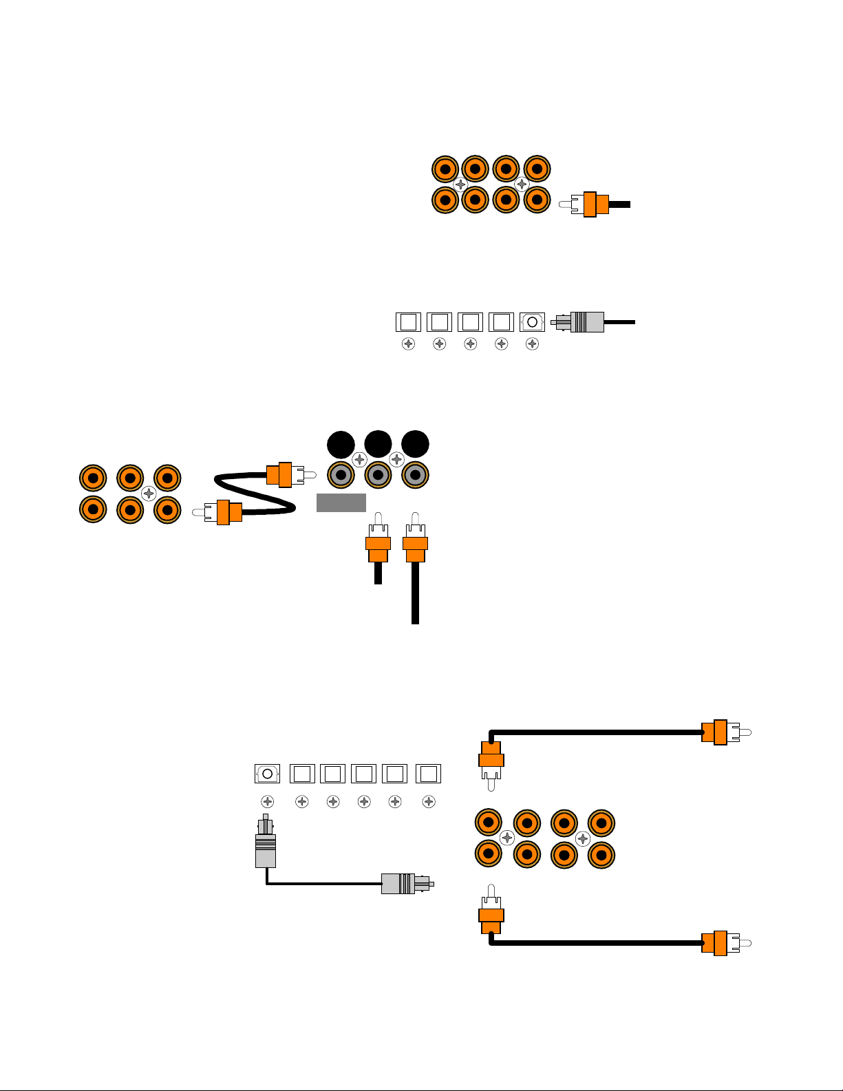
DIGITAL CONNECTIONS
g
g
g
g
Connect digital inputs (DVD, VLD, etc.) to the processor. You will need either coaxial or optic al digital inputs to
play Dolby Digital (AC-3) or DTS surround sound
processing. Digital connections are also
recommended for PCM sources. If your source has
both optical and coaxial outputs connect only one.
ZA OUT
COAX DIGITAL
TV V2 V1
Coaxial digital inputs
- standard RCA type
connectors. Attach one end of your digital coaxial
ZB OUT
SAT DVDCD
Coax digital input
from DVD output
cable to your source coaxial digital out and the other
end to the appropriate processor coaxial digital
(orange) input.
Optical digital inputs -
First, remove the cap on
the optical digital input. Save the cap. Attach one
end of your digital optical cable to your source and
OPTICAL DIGITAL
V2DVDCDSAT
V1
Optical digital output
from source
the other end to the appropriate digital input on the
back of the processor.
Dolby Digital
COAX DIGITAL
TV V2 V1
DT-1
Connecting A Laser disc Player -
(AC-3) laser discs use a special technique called
AC-3 RF to encode the Dolby Digital bitstream. If the
laser disc player is capable of playing back Dolby
Digital discs it will have a separate output for this
bitstream in addition to the normal coaxial and/or
MAIN
OUTPUT
COAX
INPUT
AC-3 RF
optical outputs. Do not connect the AC3-RF output
directly to your processor. The AC-3 RF bitstream
INPUT
must first be converted to a normal (non-RF) Dolby
SAT DVDCD
Digital type signal. It is recommended that a B&K
DT-1 be used to convert and select between the
Coax digital input
from VLD output
AC-3 RF input
from VLD output
Laser’s AC-3 RF and PCM/DTS signals. T he output
from a DT-1 will automatically select between the
connected PCM/DTS bitstreams and the converted
AC-3 RF Dolby Digital signal. Other AC-3 RF to
Dolby Digital decoders may not make this switch
automatically. Connect the laser disc’s AC3-RF output to the DT-1’s AC- 3 RF input. Connect either the laser dis c
player’s PCM coaxial or optical digital output (not both) to the DT-1’s c oaxial or optical input. Connect the DT-1’s
coaxial output to the desired coaxial digital input on your processor.
Digital Outputs -
Separate
and independent coax
digital outputs are available
for Zone 1 (A) and Zone 2
(B). Connect to a digital
recorder (CD-R, mini disc,
DAT, personal computer,
OUT V1
OPTICAL DIGITAL
V2DVDCDSAT
ZA OUT
Zone 1 (A) Coax digital output
to di
ital recorder
COAX DIGITAL
TV V2 V1
etc.) These signals ar e the
same as the incoming
digital signal from the
selected source on each
zone. If your digital
recorder has both optical
and coaxial inputs you
need only connect one.
Zone 1 (A) Optical digital output
ital recorder
to di
ZB OUT
SAT DVDCD
Zone 2 (B) Coax di
to di
ital recorder
ital output
Zone 1 (A) selected digital
input is converted to both
coaxial and optical. You
may connect one digital recorder to the optical output and another recorder to the coaxial. Zone 2 (B) digital output
is coax.
16
p/n 12857 Rev. 0717A
Page 20
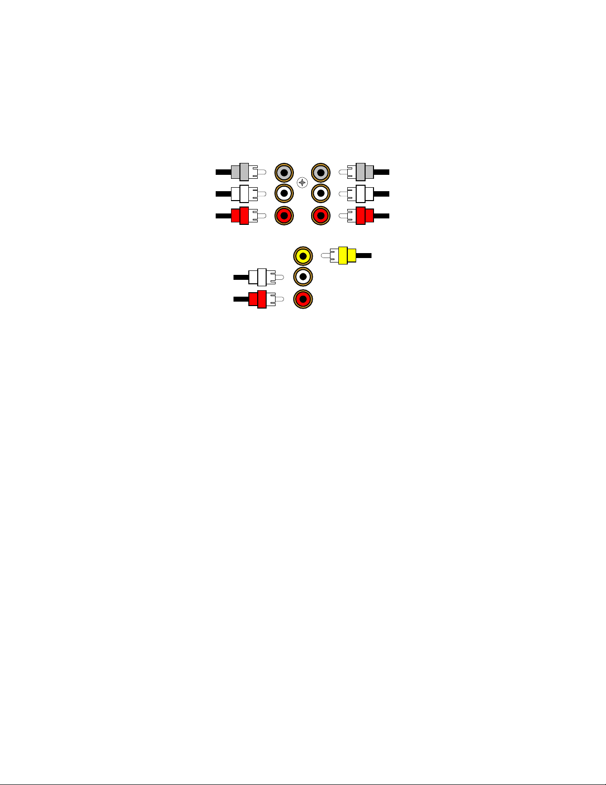
SURROUND OUTPUTS
Your processor has multiple surround outputs for use with external amplifier(s) or powered speakers. The
Reference 30 processor allows THX Surr ound EX compatibility via it’s two Surround Back ‘S BACK’ processor
outputs.
Here is a typical processor surround output setup
Connect to the Subwoofer 'SW'
power amplifier input
Connect to the Surround Left
'Sl' power amplifier input
Connect to the Surround Right
'Sr' power amplifier input
Connect to the Surround Back Left
'Sbl' power amplifier input
Connect to the Surround Back Right
'Sbr' power amplifier input
Subwoofer Output -
Connect an RCA cable from the proc essor’s SW output (part of the s urround outputs). If
:
ZA AUDIO OUT
SUB CENTER
SURR
FRONT
S BACK
Connect to the Center power
amplifier input
Connect to the Left Front
power amplifier input
Connect to the Right Front
power amplifier input
Connect to Zone 1 (A)
composite video monitor input
your subwoofer does not contain its own amplifier you will need to purchase an external B&K or other power
amplifier. Connect the proces sor’s SW output to the audio input of the external amplifier. Connec t the external
amplifier’s speaker output to your subwoofer.
17
p/n 12857 Rev. 0717A
Page 21
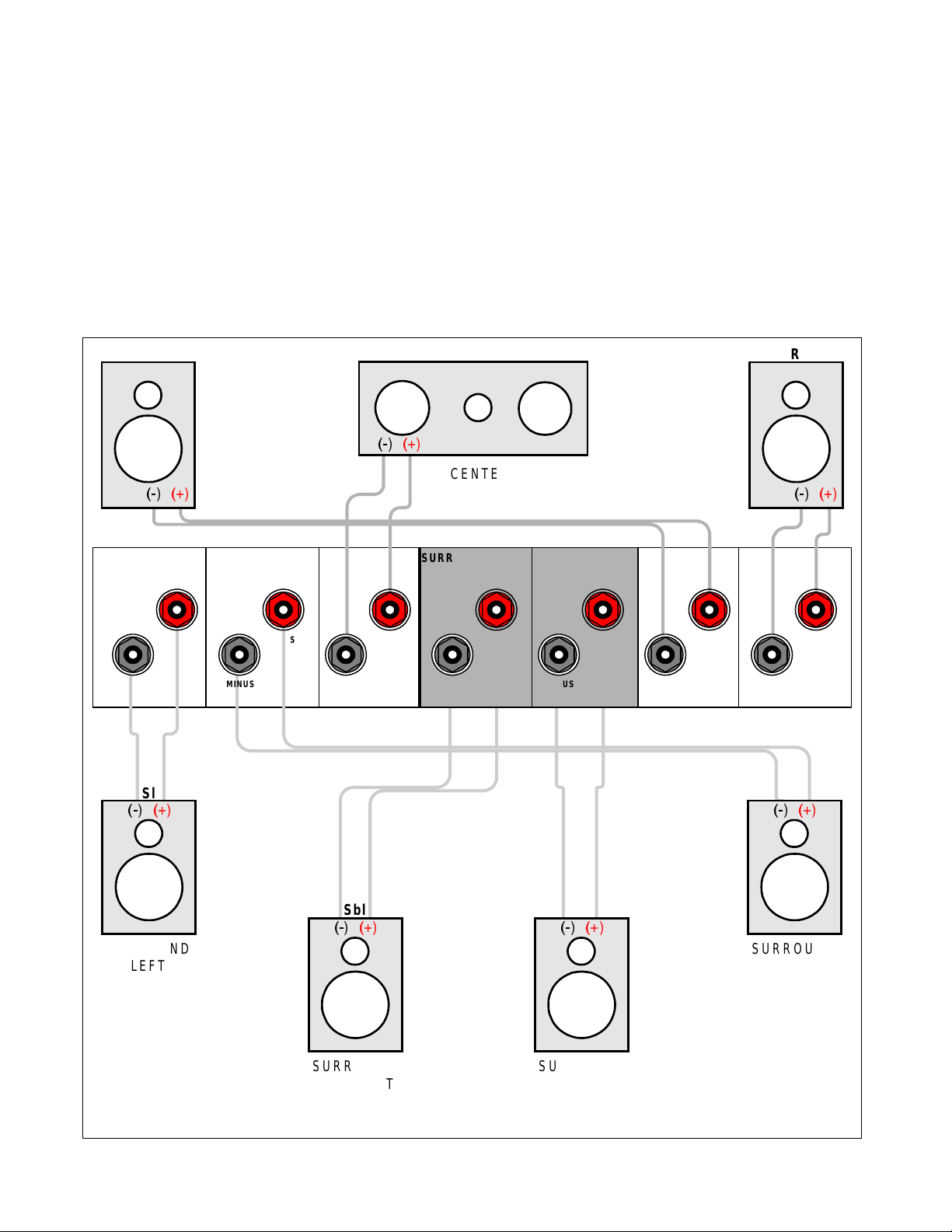
SURROUND SPEAKER OUTPUT CONNECTIONS
Connect the A/V System Controller’s surround outputs to your external amplifier(s) or powered speakers as
described previously. Connect your speakers to your external amplifier(s) as shown below.
L
FRONT
LEFT
SURROUND LEFT SURROUND RIGHT
PLUS
MINUS
PLUS
MINUS
Sl
CENTER
MINUS
SURROUND BACK
PLUS
MINUS
C
CENTER
LEFT
PLUS
SURROUND BACK
RIGHT
PLUS
MINUS
R
FRONT
RIGHT
FRONT LEFT FRONT RIGHT
PLUS
MINUS
PLUS
MINUS
Sr
SURROUND
LEFT
Sbl
SURROUND
BACK LEFT
18
Sbr
SURROUND
RIGHT
SURROUND
BACK RIGHT
p/n 12857 Rev. 0717A
Page 22
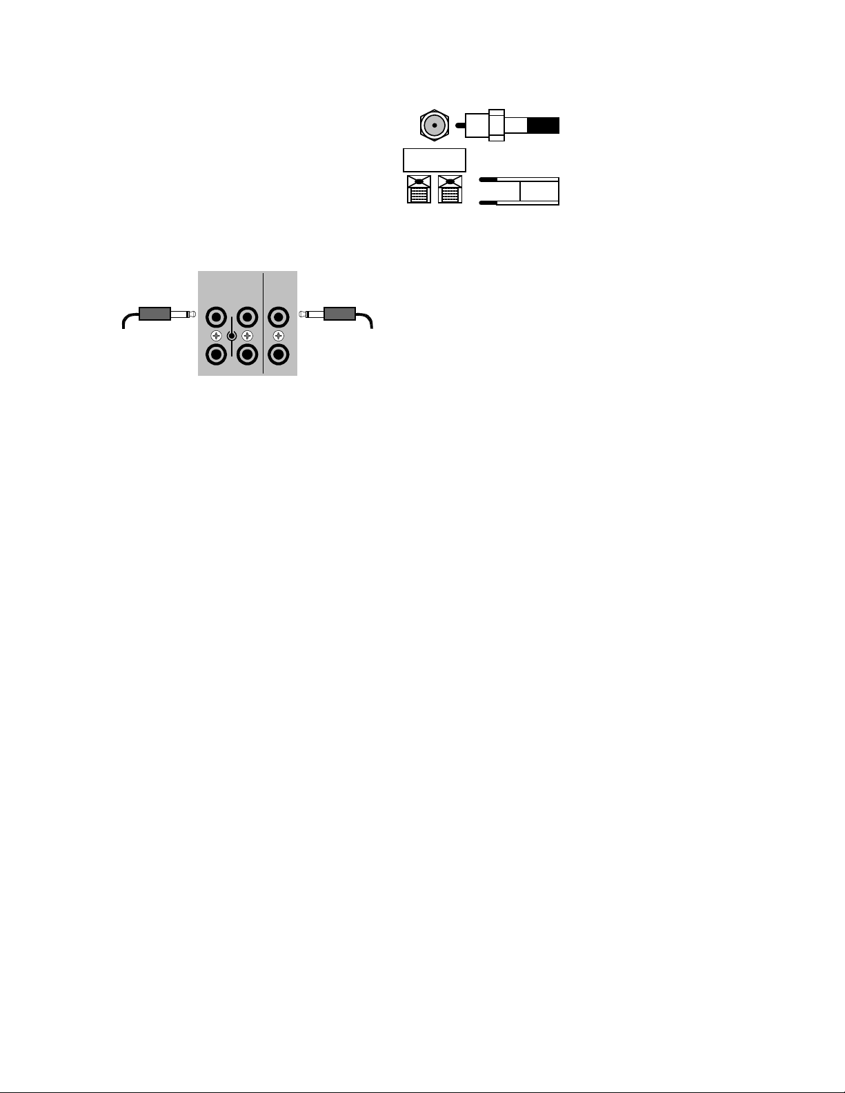
ANTENNA CONNECTIONS
The FM jack is a standard screw on F-type
connector. The AM is a push type. Strip ¼ inch of
insulation off your AM antenna wires and insert one
wire end into each hole while holding the tabs
down. Release the tabs to lock in the AM antenna
wires.
CONTROL OUTPUTS / IR INPUTS
TUNER
FM antenna
AM antenna
FM Antenna Input
from Indoor/Outdoor Antenna,
Cable Box, etc.
AM Antenna Input
from Loop Antenna
CONTROL OUT
12
+12VDC
50mA
IR IN
ZA
CAUTION!
Control Outputs -
controlling other equipment such as an external B&K
Components, Ltd. amplifier, projection screen, etc.
These connections are used for
Connect your control cable to the processor using a
3.5 mm control output
to amplifier, etc.
34
ZB
3.5 mm IR in
from remote repeater
mono 3.5 mm jack shown at left. The plug must be
wired as tip (+) and the long barrel section (-).
The Control outputs are program mable for each source in your system (see “Advanced Setup”). However, the
processor provides the following factory preprogrammed setup that should serve for most standard system
applications.
Control 1
- HEADPHONE - On (+12 VDC) when Zone 1 (A) is on and not in Headphone mode, of f when Zone 1
(A) is off or in Headphone Mode. This mode may be used for controlling external amplifiers or powered
subwoofers in Zone 1 (A).
Control 2
- Zone 2 (B). On (+12 VDC) when Zone 2 (B) is on, off (0 VDC) when Zone 2 (B) is off. This mode is
used for controlling external amplifiers, projection screens, etc. in Zone 2 (B).
Control 3
- Z1 + Z2. On (+12 VDC) when Zone 1 ( A), Zone 2 (B), or both zones are turned on. O ff (0 VDC) when
both zones are off.
Control 4
-REMOTE. It will repeat a received 38 k H z modulated IR s ignal. The processor will transmit r ec eived IR
signals even in sleep mode.
Note - The control outputs can output a maxim um of 50 m A. Check to see that the source you are connecting to
the control out requires 50 mA or less current.
WARNING - Not all manufacturers adhere to the +12 VDC control specification. Check to see if your
sources control inputs are +12 VDC compatible. Do not connect your processor’s control outputs to a
source with control or remote inputs rated at +5 VDC or other voltage rating. Damage to your source may
result.
IR Inputs -
Your processor can be controlled by a directly connected IR repeater system in combination with or in
place of the supplied remote control. Connect your IR input cable to the processor using a mono 3.5 m m jack
shown above. The plug must be wired as tip (+) and the long barrel section (-). T he inputs are standard 38kHz
modulated IR type with a voltage range of +5 to +12 VDC.
19
p/n 12857 Rev. 0717A
Page 23

FREQUENTLY ASKED QUESTIONS
My collection of equipment differs from the labels on the back of my processor, how can I hook them up?
Your processor provides 5 identical sets of inputs - V1, V2, DVD, CD, and SAT. Each of thes e has analog
audio, composite video, S-video, coaxial digital audio, and optical digital audio. It is convenient to connect
components as labeled on the back of your processor, but since all the inputs are identical, you can connect any
compatible source to any set of inputs. For ex ample, you can connect a DAT player to V1 instead of a VCR. You
can program your processor to display any 5 character name for any input (see System Setup - Inputs).
The sixth input, TV, is identical to the other s except that there is no optical digital. You can also connect
portables to any other coaxial digital input using adapters or special c ables. If you have a source with only optical
digital output don’t connect it to TV.
The seventh input, TAPE, has analog audio, com posite video and S-video, but has no digital inputs. It is
primarily intended for analog recorders s uch as VCRs or cassette decks. If you have a three-head cassette or
reel-to-reel tape deck you will prefer the TAPE input s ince it allows a full tape monitor capability. Tape monitor
allows you to listen to what is actually on the tape as you are recording it. The V2 input also provides full tape
monitor capabilities for Zone 2 (B) . If you don’t use Zone 2 (B) you can use V2 as a second independent analog
tape monitor loop. V1 includes a line level output but does not provide true tape monitor capability.
My DVD player (or other source) has both optical and coaxial digital outputs. Should I connect both?
No, connect only one digital cable per source.
Do I need an AC-3 RF demodulator (B&K DT-1 or equivalent) to playback Dolby Digital
DVDs?
No, this is required only for Dolby Digital laser discs.
Do I need an AC-3 RF demodulator (B&K DT-1 or equivalent) to playback DTS laser discs?
No, this is required only for Dolby Digital laser discs.
Do I need to connect both analog and digital audio from my DVD player (or other digital audio source) to
the processor?
In general, it is simpler to connect both. However, if you can meet all of the following criteria you need only
connect digital:
1. I do not use Zone 2 (B). (Zone 2 (B) is analog only - if you use Zone 2 (B) you must c onnec t both lef t and right
analog to hear audio.)
2. I do not own any old laser discs. (Early laser discs contained only analog audio tracks - you must connect both
left and right analog audio to play these back.)
3. I do not use Tape Monitor. (It is possible to tape digital-only sources. However, if you wish to listen directly to
the tape as you are recording - you must connec t both lef t and r ight analog audio - the tape m onitor loops are
strictly analog.)
If the tape monitor loop is strictly analog, how do I make an analog recording of a digital-only source?
Do not select TAPE. Select the source you wish to record. Select STEREO 9, the LtRt mode. If that
source is digital, the converted digital-to- analog will appear at the tape and V1 outputs. V2 out, lik e Z one 2 ( B) out,
is analog only. (See also Operation - Zone 1 Operation - Mode.)
I want to make direct digital recordings from my CD player (or other digital source) on my CD Recorder,
DAT (or other digital recorder). Can my processor make this connection for me?
Yes, your processor’s digital outputs act much lik e the analog tape outputs. W hen you select a source, if
that source has a digital connection to your processor, then that digital signal will appear on the processor’s
coaxial and optical digital outputs. Simply connect all of your sources digital outputs to your processors digital
inputs. You can then connect up to three digital recorder inputs to your processor’s three digital outputs.
20
p/n 12857 Rev. 0717A
Page 24

My laser disc player (or other digital source) has only optical output, but my CD recorder (or other digital
recorder) has only coaxial input. Do I need some sort of converter to make direct digital recordings?
No, your processor will convert optical to c oaxial and coaxial to optic al. T he c urrently selected digital input
(optical or
coaxial) will appear at both of the processor’s digital outputs (optical and coaxial).
Do I need to connect both analog and digital audio from my processor to my CD, DAT, MD, etc. recorder?
In general, yes. If all of the sources you wish to record are digital, then you need only connect digital to
your recorder. However, your processor does not provide digital outputs f or non-digital inputs. If you wish make a
digital recording from an analog-only source you must also connect analog from your processor (Tape or V1 out)
to your recorder.
Can I connect a phonograph directly to my processor?
No, you will need a separate outboard phono preamplifier. The output of the phono preamp can then be
connected to any analog input on your processor. We recom mend our Phono 10 phono preamp. In addition to it’s
superb analog audio processing, it has an option for S/PDIF coax output. Talk to the dealer where you purchased
your processor.
Do I need to connect both S-video and composite video to my processor?
If all of your video equipment has S- video then you need only connect S-video. S-video is a higher quality
video format and you will probably not want to use composite. If all or most of your video equipment is com posite
then it is simplest to just connect the composite and omit S-video.
Can I connect mixed composite and S-video sources?
Yes, but your processor will not convert S-video to compos ite or composite to S-video. If your monitors
and VCRs accept only composite video then ther e is no point in c onnec ting S-video from other sourc es . If you use
mixed S-video and com posite sourc es you must connec t both
You will need to change your monitor or VCR S-video / composite inputs manually when you change sources. This
can normally be done via the monitor’s or VCR’s remote control (or the supplied universal remote). Some monitors
or VCRs may require you to physically disconnect S-video before they will accept composite video. Some m onitors
are capable of automatic switching between S-video and com posite. Your processor must be setup properly in
order to work with auto switching monitors - refer Setup Displays.
S-video and composite to your monitors and VCRs.
To assist you, the processor’s on-screen display will tell you what video is currently selected whenever you
change sources or hit the SEL (rem ote) or ENTER ( remote or front panel) key, but it cannot switch your monitor or
VCR input for you.
If you are watching S-video, but the source is composite video only, you will see “Switch
Monitor to Composite” on your Monitor. If you are watching Composite video but your source is S-video only , you
will see “Switch Monitor to S-video” on your monitor
manual monitors.
. These displays appear only if your processor is setup f or
Can I connect mixed composite and S-video monitors and VCRs?
Yes, but you must connect both S-video and composite f rom all of your sources - your processor will not
convert between S-video and composite. Refer to the previous question if not all of your sources have both
S-video and composite outputs.
For example, it is com m on to have an S-video monitor and a compos ite VCR. Connect the m onitor to the
Zone 1 (A) S-video and composite outputs and the VCR to the V1 or TAPE composite output. The composite
inputs will appear at the composite outputs for TAPE and V1. (The S-video inputs also appear at the TAPE and V1
S-video outputs, but, in this example, they are not connected.) To prevent f eedback, TAPE IN will not appear on
TAPE OUT and V1 IN will not appear on V1 OUT - this also applies to the audio outputs. Zone 2 (B) works the
same for Zone 2 (B) OUT and V2 OUT with feedback prevention on V2.
Things get a bit more com plicated for the Zone 1 (A) output because it contains your processor’s internal
on-screen display system. You must be sure that you tell your processor if you have a monitor which can
automatically switch between S-video and composite outputs, or one which must be manually switched (see Setup
Displays)
21
p/n 12857 Rev. 0717A
Page 25

SETUP
For best results, perf orm the following set up procedure when you initially install your processor and anytime you
change or add sources, speakers, etc. or when you rearrange your listening area
THE MENU SYSTEM
Setup of your processor will require you to navigate through the menu system. W e recommend that you use a
video monitor connected to the Zone 1 (A) output along with the remote c ontrol provided with your processor. It is
also possible to set up your processor from the f ront panel. Do not leave your video monitor on with the processor
in the menu system for long periods of time. This can res ult in permanently burning the menu display into your
monitor’s screen. This would take several hours so there is no danger of it happening during normal setup
procedures. The following are general instructions for using the menu system. A complete guide to the menu
system is included at the back of this manual.
MENU
- If you are not already in the menu system, the MENU button will activate the menu system. Once you are
in the menu system, the MENU button will return you to the next higher level menu or , if you are already at the
highest level, it will exit from the menu system.
UP/DOWN ARROWS
menu selection. The currently active menu line is highlighted in a contrasting color.
SEL (remote) or ENT ER (remote or front panel)
Use the UP/DOW N ARROWS to move to the des ired menu line. Pressing SEL or ENTER will activate the nex t
menu.
NUMERIC KEYS (remote only)
corresponding line number . If there is another menu below that line it will be activated immediately (no ENTER
required).
LEFT/RIGHT ARROWS (remote) or VOLUME KNOB (front panel)
one of the processor settings. Use the UP/DOWN ARROWS to move to the desired menu line. Pressing the
LEFT/RIGHT ARROWS will change the setting. There ar e no LEFT/RIGHT ARROWS on the front panel. While in
the menu system, the VOLUME KNOB acts as the LEF T/RIGHT ARRO W S. This means that you will not be able
to adjust the volume from the front panel while in the menu system . The remote control volum e will work in mos t
menus.
TEXT EDITING
current (blinking) charac ter. Use the LEFT/RIGHT ARROW S (or VOLUME KNOB) to m ove to another character
position.
EXIT (remote only) UNIVERSAL REMOTE
controls the selected device. To r eturn c ontr ol to your processor , you must pres s B&K or AUDIO .
that your remote is set to B&K or (AUDIO) before attempting to control your processor. B&K or (AUDIO)
will be displayed in the remote’s LCD window.
- Once you are in the menu system, us e the UP/DOW N ARROW S to move to the desired
- Some menu selections caus e another menu to be activated.
- From the remote control you may also go directly to a menu line by typing the
- Some m enu s elec tions allow you to change
- some m enu selections will require you to edit text. Use the UP/DOWN ARROWS to change the
From the remote control you may instantly EXIT the menu system.
- Remember that when you press a source button (DVD, CD, etc.) the remote now
ALWAYS check
22
p/n 12857 Rev. 0717A
Page 26
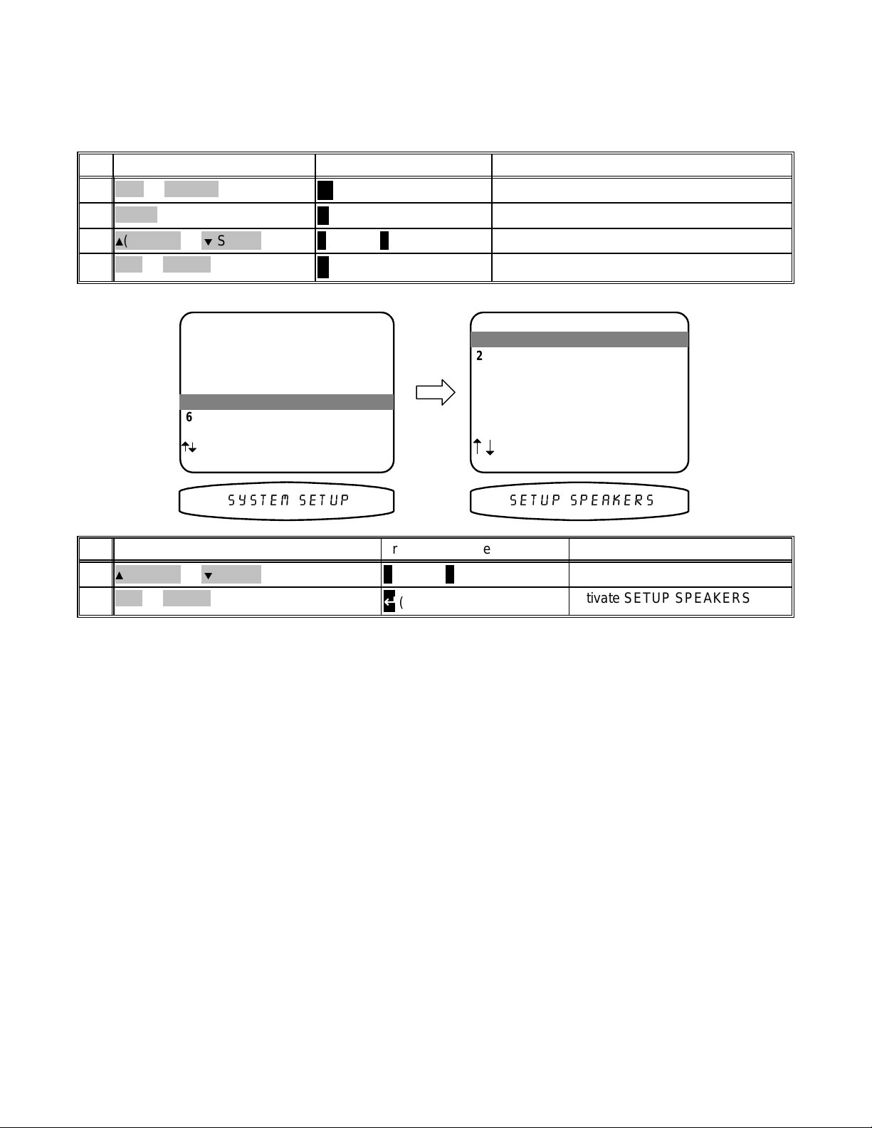
SYSTEM SETUP
You should always perform System Setup after fir st installing your processor and af ter adding/changing speak ers
or sources or rearranging your listening area. Check that the remote is in B&K mode.
ActionFrom Front PanelFrom Remote
B&K or POWER1
MENU2
3
(PAUSE) or (STOP)
SEL or ENTER4
MAIN MENU
1 Zone 1 Operation
2 Zone 2 Operation
3 Zone 1 Favorite Presets
4 Zone 2 Favorite Presets
5 System Setup
5 System Setup
6 Memory Backup/Restore
next item SEL select
MENU exit menu system
1
(PAUSE) or
SEL or ENTER2
(STOP)
A
SLEEP
∠ MENU
∧
(UP) or ∨ (DOWN)
↵
(ENTER)
∧
(UP) or ∨ (DOWN)
↵
(ENTER)
turn on processor
activate menu system
move to System Setup
activate SETUP SYSTEM
SETUP SYSTEM
1 Speakers
1 Speakers
2 Displays
3 Inputs
4 Presets
next item SEL select
MENU main menu
6(783 63($.(566<67(0 6(783
ActionFrom Front PanelFrom Remote
move to Speakers
activate SETUP SPEAKERS
Speakers
The speakers m enu lets you tell your processor how many speakers you have in your system, the relative size of
the speakers, and their location in the room. T his is the most important setup procedure you will perform. The
processor comes from the factory setup for 7 small speakers and a subwoofer. If this does not match your
speakers then audio inf ormation will be lost. For exam ple, if you do not currently have a center channel speak er
and you do not perform this s etup procedure, the center channel inform ation will be lost. If you perform this setup
correctly, the processor will know that you have no center channel speaker and send this inform ation to your front
left and right speakers (along with the normal front left and right information) so no audio information is lost.
Speaker Size
Speaker size generally refers to the size of your speakers. Audio material, particularly Dolby Digital and DTS
movies, often contain lar ge amounts of bass. If this bass infor mation is sent to sm all speakers that are incapable
of reproducing so muc h bass, then the bass infor mation will be lost or distorted. MANY SMALL SPEAKERS MAY
BE DAMAGED BY TOO MUCH BASS. By telling your processor the size of your speakers, it will be able to
intelligently route the bass to speakers that can reproduce it correc tly. Typically, all bookshelf or satellite speak ers
are considered sm all. Smaller floor standing speakers with single woofers 8” or less should also be cons idered
small. Floor standing s peakers with 10” or larger woofers or m ultiple smaller woofers may be consider ed large.
These are general guidelines only - if you are unsure consult your speaker manufacturer or check with the dealer if
they are unsure. If you have all small speakers we str ongly recommend use of a subwoofer. If your front lef t and
right speakers (or m ore) are large then you may not require a subwoofer, but you may still get better results using
a subwoofer, especially with Dolby Digital and DTS movies. All THX cer tified speakers are small, regardless of
their physical size, and should be used in audio systems along with a subwoofer.
23
p/n 12857 Rev. 0717A
Page 27

Set the size for your front left and right, ‘L’ and ’R’ speakers - You must have front speakers.
p
p
p
q
p sy
j
p sp
j
p sp
1
(PAUSE) or (STOP)
SEL or ENTER2
3
(PAUSE) or (STOP)
4
(REW) or(FF)
Small
THX
Large
SETUP SPEAKERS
1 Speaker Size
eaker Size
1 S
eaker Location
2 S
eaker Levels
3 S
4 Crossovers + LFE
5 Room E
next item SEL select
MENU setu
ualization
stem
63($.(56 6,=(
∧ (UP) or ∨ (DOWN)
(ENTER)
↵
∧ (UP) or ∨ (DOWN)
Front Bass to SW
Front Hi-Pass to Front
Front Full Range to Front
SETUP SPEAKER SIZE
1 Front Small THX
1 Front Small THX
2 Center Small THX
3 Surround Small THX
4 Surround Back 2 Small THX
5 Subwoofer Yes THX
next item ad
MENU setu
)5217 60$//
Front Bass to SW
Front Hi-Pass to Front
ust
eakers
ActionFrom Front PanelFrom Remote
move to Speaker Size
activate SETUP SPEAKER SIZE
move to Front
choose speaker sizeVOLUME KNOB
Subwoofer NoneSubwoofer Yes THX Subwoofer UltraFront setting
Front Bass is *
Front Hi-Pass to Front
Front Full Range to FrontFront Full Range to FrontFront Bass to SW
Set the size for your center ‘C’ speaker -
1
(PAUSE) or (STOP))
2
(REW) or(FF)
∧ (UP) or ∨ (DOWN)
Subwoofer Yes THXSubwoofer UltraCenter
setting
None
Small
THX
Center Bass to SW
Center Hi-Pass to Front
Center Bass to SW
Center Hi-Pass to Center
Center Hi-Pass to Front
Center Bass to SW
Center Hi-Pass to Center
Large
Center Full to Center
SETUP SPEAKER SIZE
1 Front Small THX
2 Center Small THX
2 Center Small THX
3 Surround Small THX
4 Surround Back 2 Small THX
5 Subwoofer Yes THX
next item ad
MENU setu
&(17(5 60$//
ust
eakers
ActionFrom Front PanelFrom Remote
move to Center
choose speaker sizeVOLUME KNOB
Subwoofer None
Front Large
Center Full to FrontCenter Bass to SW
Center Bass is *
Center Hi-Pass to Center
Subwoofer None
Front Small
Center Bass is *
Center Hi-Pass to Front
Center Bass is *
Center Hi-Pass to
Center
Center Full to CenterCenter Full to CenterCenter Full to CenterCenter Bass to SW
24
p/n 12857 Rev. 0717A
Page 28

Set the size for your surround left and right, ‘Sl’ and ‘Sr’ speakers -
j
p sp
j
p sp
SETUP SPEAKER SIZE
1 Front Small THX
2 Center Small THX
3 Surround Small THX
3 Surround Small THX
4 Surround Back 2 Small THX
5 Subwoofer Yes THX
1
(PAUSE) or (STOP)
2
(REW) or(FF)
setting
None
Small
Surround Bass to SW
Surround Bass to SW
THX
Large
Surround Bass to SW
Surround Hi-Pass to
Front
Surround Hi-Pass to
Surround
Surround Full to
Surround
next item ad
MENU setu
6855281' 60$//
∧ (UP) or ∨ (DOWN)
Subwoofer Yes THXSubwoofer UltraSurround
Surround Bass to SW
Surround Hi-Pass to
Front
Surround Bass to SW
Surround Hi-Pass to
Surround
Surround Full to
Surround
ust
eakers
ActionFrom Front PanelFrom Remote
move to Surround
choose speaker sizeVOLUME KNOB
Subwoofer None
Front Large
Surround Full to
Front
Surround Bass is *
Surround Hi-Pass to
Surround
Surround Full to
Surround
Subwoofer None
Front Small
Surround Bass is *
Surround Hi-Pass to
Front
Surround Bass is *
Surround Hi-Pass to
Surround
Surround Full to
Surround
Set the size for your surround back left and right, ‘Sbl’ and ‘Sbr’ speakers -
SETUP SPEAKER SIZE
1 Front Small THX
2 Center Small THX
3 Surround Small THX
4 Surround Back 2 Small THX
4 Surround Back 2 Small THX
5 Subwoofer Yes THX
next item ad
MENU setu
685 %$&. 60$//
ust
eakers
ActionFrom Front PanelFrom Remote
1
(PAUSE) or (STOP)
2
(REW) or(FF)
∧ (UP) or ∨ (DOWN)
move to Surround Back
choose speaker sizeVOLUME KNOB
25
p/n 12857 Rev. 0717A
Page 29

Back
j
p sp
setting
Subwoofer Yes THXSubwoofer UltraSurround
Subwoofer None
Front Large
Subwoofer None
Front Small
None
1 Small
1 Large
Surround Bass to SW
Surround Hi-Pass to
Front
Sb Bass to SW
Sb Hi-Pass to
Surround Back Left
Sb Bass to SW
Sb Full to
Surround Bass to SW
Surround Hi-Pass to
Front
Sb Bass to SW
Sb Hi-Pass to
Surround Back Left
Sb Full to
Surround Back Left
Surround Full to
Front
Sb Bass is *
Sb Hi-Pass to
Surround Back Left
Sb Full to
Surround Back Left
Surround Bass is *
Surround Hi-Pass to
Front
Sb Bass is *
Sb Hi-Pass to
Surround Back Left
Sb Full to
Surround Back Left
Surround Back Left
2 Small
THX
2 Large
Sb Bass to SW
Sb Hi-Pass to
Sbl and Sbr
Sb Bass to SW
Sb Hi-Pass to
Sbl and Sbr
Sb Bass is *
Sb Hi-Pass to
Sbl and Sbr
Sb Bass is *
Sb Hi-Pass to
Sbl and Sbr
Sb Full to Sbl and SbrSb Full to Sbl and SbrSb Full to Sbl and SbrSb Bass to SW
Sb Full to Sbl and Sbr
Setup your subwoofer ‘SW’ - In the table above, you have the flexibility to choose how bass information is
distributed to your speakers only if you have large speakers and a subwoofer as part of your home theater
speaker system. For exam ple, selecting the "Front Large” and "Subwoofer Yes THX" options, bass f rom the fr ont
left and front right c hannels will go ONLY to the front left and f ront right speakers. Bass going to the subwoofer
will only come from the LFE channel and any channels with speakers that you have designated as "Small". This
selection is preferred by THX. However, selec ting the "Front Large” and “Subwoofer Ultra" options , you will send
the bass from the f ront left and right channels to the f ront left, right AND subwoofer speak ers sim ultaneously. To
decide which setting is best for your room, once you have positioned all of your speakers, choos e the option which
gives you the most solid sounding bass.
* Note: when the subwoofer is set to None, bass is r edirec ted to r emaining large speakers. When no speaker s ar e
set to Large, and the subwoofer is set to None, bass information is lost.
SETUP SPEAKER SIZE
1 Front Small THX
2 Center Small THX
3 Surround Small THX
4 Surround Back 2 Small THX
5 Subwoofer Yes THX
5 Subwoofer Yes THX
next item ad
MENU setu
68%:22)(5 <(6
ust
eakers
ActionFrom Front PanelFrom Remote
1
(PAUSE) or (STOP)
2
(REW) or(FF)
MENU3
∧ (UP) or ∨ (DOWN)
∠ MENU
move to Subwoofer
choose subwoofer settingVOLUME KNOB
return to SETUP SPEAKERS
26
p/n 12857 Rev. 0717A
Page 30

Subwoofer Setting
p
p
p
q
p sy
g
g
g
j
p sp
Front
Large
Center
Large
Surround
Large
Surround
Back Large
None
Yes
THX
Ultra
LFE + Bass to
Front
LFE + Bass to SW
Front Bass not
Duplicated
LFE + Bass to SW
Front Bass is
Duplicated
LFE + Bass to
Center
LFE + Bass to SW
Center Bass not
Duplicated
LFE + Bass to SW
Center Bass is
Duplicated
LFE + Bass to
Surround
LFE + Bass to SW
Surround Bass not
Duplicated
LFE + Bass to SW
Surround Bass is
Duplicated
LFE + Bass to
Surround Back
LFE + Bass to SW
Sb Bass not
Duplicated
LFE + Bass to SW
Surround Back Bass
is Duplicated
Note: The subwoofer setting affects the routing of front, center, and surround bass information as shown
previously. This table shows the effect of the subwoofer setting with large speakers.
Speaker Location
Ideally your speakers will be the same distance away from your listening area. However, physical limitations
usually require placing the speaker in other than optimum locations. Your processor contains a means to
electronically move each speak ers loca tion. This allows f or superior reproduction of the directional cues available
during the playback of movie or music. Measure the distance in feet to your speakers and set each speaker
location setting to this distance. Your proces sor will electronically “move” each speaker to m aintain correct time
alignment with the listening position. You may also change the units to meters, if you prefer.
SETUP SPEAKERS
eaker Size
1 S
2 Speaker Location
eaker Location
2 S
eaker Levels
3 S
4 Crossovers + LFE
5 Room E
next item SEL select
MENU setu
ualization
stem
SPEAKER LOCATION feet
1 Left Front 10.0
1 Left Front 10.0
2 Center 10.0
ht Front 10.0
3 Ri
ht Surround 10.0
4 Ri
ht Surr Back 5.0
5 Ri
6 Left Surr Back 5.0
7 Left Surround 10.0
8 Subwoofer 10.0
next item ad
MENU setu
ust
eakers
1
(PAUSE) or (STOP)
SEL or ENTER2
3
(PAUSE) or (STOP)
4
(REW) or(FF)
5
(PAUSE) or (STOP)
6
(REW) or(FF)
MENU8
63($.(5 /2&$7,21
∧ (UP) or ∨ (DOWN)
↵ (ENTER)
∧ (UP) or ∨ (DOWN)
∧ (UP) or ∨ (DOWN)
∠ MENU
/()7 )URQW
ActionFrom Front PanelFrom Remote
move to Speaker Location
activate SPEAKER LOCATION
move to Left Front
adjust left speaker locationVOLUME KNOB
move to Center
adjust center speaker locationVOLUME KNOB
repeat for all speakersrepeat 5-6 for each speakerrepeat 5-6 for each speaker7
return to SETUP SPEAKERS
27
p/n 12857 Rev. 0717A
Page 31

Speaker Levels
p
p
p
q
p sy
g
g
g
j
p sp
Speaker level calibration allows you to equalize the volume levels of each s peaker to m ake up for dif ferences in
speaker characteris tics and distances from the listener to the speaker s. For best results it is important that you
perform this calibr ation when you initially install your processor, whenever you change speakers, and whenever
you rearrange your listening area. The following adjustment must be done for proper room calibration to THX
reference level. Sit or plac e the SPL (Sound Pressure Level) meter in your norm al listening spot. Check that you
are in SETUP SPEAKERS and that your remote is in B&K mode. Note that if you have turned a speaker OFF in
the SPEAKER SIZE SETUP menu then you will not be able to select that speaker in the SETUP SPEAKER
LEVELS menu. Set the SPL meter to use 75 dB SPL, C W eighting and SLOW response. Adjust each speak ers
level up or down to achieve the desired THX reference level of 75 dB SPL.
Note: if you must do this adjustment with out the aid of an SPL meter, you may do it by ear and adjust each
speaker for equal volume. You may wish to go through the speakers several times to get a reasonable result.
Also note that the VOLUME on the remote will not function in this menu.
1
(PAUSE) or (STOP)
SEL or ENTER2
3
(PAUSE) or (STOP)
4
(REW) or(FF)
5
(PAUSE) or (STOP)
6
(REW) or(FF)
MENU8
SETUP SPEAKERS
eaker Size
1 S
eaker Location
2 S
3 Speaker Levels
eaker Levels
3 S
4 Crossovers + LFE
5 Room E
next item SEL select
MENU setu
ualization
stem
63($.(5 /(9(/6
∧ (UP) or ∨ (DOWN)
↵ (ENTER)
∧ (UP) or ∨ (DOWN)
∧ (UP) or ∨ (DOWN)
∠ MENU
SETUP SPEAKER LEVELS
1 Left Front 0.0 dB
1 Left Front 0.0 dB
2 Center 0.0 dB
ht Front 0.0 dB
3 Ri
ht Surround 0.0 dB
4 Ri
ht Surr Back 0.0 dB
5 Ri
6 Left Surr Back 0.0 dB
7 Left Surround 0.0 dB
8 Subwoofer 0.0 dB
next item ad
MENU setu
/()7 )URQW
ust
eakers
ActionFrom Front PanelFrom Remote
move to Speaker Levels
activate SETUP SPEAKER LEVELS
move to Left Front
adjust left level to a convenient reference levelVOLUME KNOB
move to Center
adjust center level to match leftVOLUME KNOB
repeat until all levels matchrepeat 5-6 for each speakerrepeat 5-6 for each speaker7
return to SETUP SPEAKERS
28
p/n 12857 Rev. 0717A
Page 32

Crossovers + LFE
p
p
p
q
p sy
g
j
p sp
g
j
p sp
Usually these settings may be left set to the fac tory defaults. However, your processor allows ‘fine tuning’ of the
system parameters most useful in setting up a high end audio system.
Set the high and low pass filters’ crossover frequency -
This sets the frequency at which bass tones are
removed from the small main speak ers and sent to the subwoofer. If you use very small main speakers you may
wish to raise the crossover above 80 Hz. You may get better results with fairly large speakers by setting them to
small and using a low crossover frequency so only the lowest tones are sent to the subwoofer. THX certified
speakers are specifically designed for use with an 80 Hz crossover setting.
SETUP SPEAKERS
eaker Size
1 S
eaker Location
2 S
eaker Levels
3 S
4 Crossovers + LFE
4 Crossovers + LFE
5 Room E
next item SEL select
MENU setu
ualization
stem
63($.(5 /(9(/6
SETUP CROSSOVERS + LFE
1 Crossover 80.0 Hz THX
1 Crossover 80.0 Hz THX
h Pass 12.0 dB THX
2 Hi
3 Low Pass 24.0 dB THX
4 Peak Limiter 0.0 dB
5 LFE Level 0.0 dB
6 DTS LFE Mode Movie
8 Subwoofer Phase Normal
next item ad
MENU setu
&526629(5 +=
ust
eakers
ActionFrom Front PanelFrom Remote
1
(PAUSE) or (STOP)
SEL or ENTER2
3
(PAUSE) or (STOP)
4
(REW) or(FF)
∧ (UP) or ∨ (DOWN)
↵ (ENTER)
∧ (UP) or ∨ (DOWN)
move to Crossovers + LFE
activate SETUP CROSSOVERS + LFE
move to Crossover
adjust frequency to desired valueVOLUME KNOB
Set the high pass filters slope - A crossover doesn’t simply send all content above 81 Hz to the main speak ers
and all content below 79 Hz to the sub. Instead there is a gradual transition. The crossover point is the fr equency
at which the amount of inf ormation in the sub and m ain speaker is equal. The cr ossover slope determines how
gradual or abrupt this transition occ urs. More gr adual slopes gener ally result in a sm oother trans ition fr om m ain to
sub. However, gradual transitions can cause distortion in s mall main speak ers because too m uch bass is sent to
them. Gradual transitions with higher cr oss over settings c an als o caus e the per ceived location of a sound to move
from the correc t main s peaker to the s ub’s location. TH X speak ers ar e specific ally designed to use a 24 dB slope
for the subwoofer and a 12 dB slope for the main speakers.
SETUP CROSSOVERS + LFE
1 Crossover 80.0 Hz THX
h Pass 12.0 dB THX
2 Hi
2 High Pass 12.0 dB THX
3 Low Pass 24.0 dB THX
4 Peak Limiter 0.0 dB
5 LFE Level 0.0 dB
6 DTS LFE Mode Movie
7 Subwoofer Phase Normal
next item ad
MENU setu
+,*+ 3$66 '%
ust
eakers
ActionFrom Front PanelFrom Remote
1
(PAUSE) or (STOP)
2
(REW) or(FF)
∧ (UP) or ∨ (DOWN)
move to High Pass
adjust filter slope to desired valueVOLUME KNOB
29
p/n 12857 Rev. 0717A
Page 33

Set the low pass filters slope -
g
j
p sp
g
p p
j
p sp
g
p
j
p sp
SETUP CROSSOVERS + LFE
1 Crossover 80.0 Hz THX
h Pass 12.0 dB THX
2 Hi
3 Low Pass 24.0 dB THX
3 Low Pass 24.0 dB THX
4 Peak Limiter 0.0 dB
5 LFE Level 0.0 dB
6 DTS LFE Mode Movie
7 Subwoofer Phase Normal
next item ad
MENU setu
ust
eakers
/2 3$66 '%
ActionFrom Front PanelFrom Remote
1
(PAUSE) or (STOP)
2
(REW) or(FF)
∧ (UP) or ∨ (DOWN)
move to Low Pass
adjust filter slope to desired valueVOLUME KNOB
Set the peak limiter - The peak lim iter is designed to limit the max imum level of bass inform ation. W hen set to
0.0 dB (default) the limiter is disabled. If your system is being used with a subwoofer not incorporating it’s own
limiter or have no subwoofer, then the peak limiter may need to be set to allow proper operation.
Warning - the peak limiter test tone may result in extremely high volume levels
Peak limiter level c alibration allows you to set the m aximum obtainable volume sent to the speakers reproducing
bass information. For best results it is important that you perform this calibration when you initially install your
processor, or whenever you change speaker s. You set this parameter by ear using the test tone supplied when
entering the peak limiter. Sit in your normal listening spot. Check that you are in SETUP CROSSOVERS + LFE
and that your remote is in B&K mode. Moving to Peak Lim iter and pressing SEL or ENT ER activates a noise tes t
tone which will aid in adjusting the level to the point at which the bass speakers sound like they are having difficulty
reproducing the test tone. Onc e this level is achieved, reduce the adjustment 1 dB and pres s the SEL button on
the remote to save the peak limit setting. If the level is inc reased all the way to 0 dB with no perceived distortion,
then just leave the setting at 0 dB. If the correct values is known, the peak limiter may be set without the use of the
test tone.
1
(PAUSE) or (STOP)
SEL or ENTER2
3
(REW) or(FF)
SEL or ENTER4
SETUP CROSSOVERS + LFE
1 Crossover 80.0 Hz THX
h Pass 12.0 dB THX
2 Hi
3 Low Pass 24.0 dB THX
4 Peak Limiter 0.0 dB
4 Peak Limiter 0.0 dB
5 LFE Level 0.0 dB
6 DTS LFE Mode Movie
7 Subwoofer Phase Normal
SEL to setu
next item ad
MENU setu
eak limiter
ust
eakers
/,0,7 '%
∧ (UP) or ∨ (DOWN)
↵ (ENTER)
↵ (ENTER)
30
SETUP CROSSOVERS + LFE
1 Crossover 80.0 Hz THX
h Pass 12.0 dB THX
2 Hi
3 Low Pass 24.0 dB THX
4 Peak Limiter -24.0 dB
4 Peak Limiter 0.0 dB
5 LFE Level 0.0 dB
6 DTS LFE Mode Movie
7 Subwoofer Phase Normal
SEL to save
next item ad
MENU setu
eak limiter
ust
eakers
/,0,7 '%
ActionFrom Front PanelFrom Remote
move to Peak Limiter
activate the peak limiter test tone
adjust level to desired valueVOLUME KNOB
saves the peak limiter value
p/n 12857 Rev. 0717A
Page 34

Set your LFE (.1) channel level - Usually this will be set to 0.0 dB (default). However, if you have no subwoofer
g
j
p sp
g
j
p sp
you may wish to reduce the low frequency effects (LFE) channel to lessen its contribution to the bass going to your
remaining large speaker s . Or, even with a subwoofer, you may just wish to reduce the overall LFE level, especially
in an apartment situation. Note that this affects only the separate LFE (.1) channel available on Dolby Digital and
DTS material it has no effect on the reproduction of normal bass from the front, center, or surround channels.
SETUP CROSSOVERS + LFE
1 Crossover 80.0 Hz THX
h Pass 12.0 dB THX
2 Hi
3 Low Pass 24.0 dB THX
4 Peak Limiter 0.0 dB
5 LFE Level 0.0 dB
5 LFE Level 0.0 dB
6 DTS LFE Mode Movie
7 Subwoofer Phase Normal
next item ad
MENU setu
/)( /9/ '%
ust
eakers
ActionFrom Front PanelFrom Remote
1
(PAUSE) or (STOP)
2
(REW) or(FF)
∧ (UP) or ∨ (DOWN)
move to LFE Level
adjust level to desired valueVOLUME KNOB
Set DTS LFE (.1) channel mode preference - Usually this will be set to Movie (default). However, s ome DTS
music mater ial is mixed for a reduced LFE setting and may sound more natural with this set to Music. Note that
this affects only the separate LFE (.1) c hannel available on DT S m aterial and has no eff ect on the r eproduction of
normal bass from the front, center, or surround channels.
SETUP CROSSOVERS + LFE
1 Crossover 80.0 Hz THX
h Pass 12.0 dB THX
2 Hi
3 Low Pass 24.0 dB THX
4 Peak Limiter 0.0 dB
5 LFE Level 0.0 dB
6 DTS LFE Mode Movie
6 DTS LFE Mode Movie
7 Subwoofer Phase Normal
next item ad
MENU setu
ust
eakers
'76 /)( 086,&
ActionFrom Front PanelFrom Remote
1
(PAUSE) or (STOP)
2
(REW) or(FF)
∧ (UP) or ∨ (DOWN)
31
move to DTS LFE Mode
adjust to desired valueVOLUME KNOB
p/n 12857 Rev. 0717A
Page 35

Set subwoofer phase - In addition to the subwoofer location adjustment (see Speaker Location above), your
g
j
p sp
processor has an option to ‘invert the phase’ of the information sent to the subwoofer. This adjustment is
sometimes needed to correct ‘lack of low end’ problems created with the interac tion between the subwoofer and
other large speakers in a listening r oom. The correct subwoofer phase adjustment is the one which allows the
loudest listening level.
SETUP CROSSOVERS + LFE
1 Crossover 80.0 Hz THX
h Pass 12.0 dB THX
2 Hi
3 Low Pass 24.0 dB THX
4 Peak Limiter 0.0 dB
5 LFE Level 0.0 dB
6 DTS LFE Mode Movie
7 Subwoofer Phase Normal
7 Subwoofer Phase Normal
1
(PAUSE) or (STOP)
2
(REW) or(FF)
MENU3
MENU4
next item ad
MENU setu
68% 3+$6( ,19(57
∧ (UP) or ∨ (DOWN)
∠ MENU
∠ MENU
ust
eakers
ActionFrom Front PanelFrom Remote
move to DTS LFE Mode
adjust to desired valueVOLUME KNOB
return to SETUP SPEAKERS
return to SETUP SYSTEM
32
p/n 12857 Rev. 0717A
Page 36

Room Equalization
Usually these settings may be left set to the factory defaults. However, theses settings allow you to correct or
reduce the various tonal errors that occur during reproduction of audio in a home theater.
The room equalization menu allows for two types of adjustments.
1) A notch filter that allows you to ‘Notch’ or reduce the accentuated bass created in a room with multiple
speakers (
available during THX listening mode
) (see Setting up the notch filter).
2) Variable bass and treble controls (
not available during THX listening mode
) allow you to configure a default
‘Variable EQ’ setting that best suits your listening room needs.
SETUP SPEAKERS
1 Speaker Size
2 Speaker Location
3 Speaker Levels
4 Crossovers + LFE
5 Room Equalization
5 Room Equalization
next item SEL select
MENU setup system
5220 (48$/,=(
SETUP ROOM EQUALIZATION
Test Tone 100.0 Hz Off
Notch 100.0 Hz 0.0 dB
Notch Width 97.6 - 102.4 Hz
Bass 100.0 Hz 0.0 dB
Treble 10.0 kHz 0.0 dB
next item adjust
MENU setup system
100.0 Hz
7(67 721( 2))
ActionFrom Front PanelFrom Remote
1
(PAUSE) or (STOP)
SEL or ENTER2
Using the test tone generator -
∧ (UP) or ∨ (DOWN)
↵ (ENTER)
your processor has a low frequency sine wave generator (20 to 300 Hz) available
move to Room Equalization
activate SETUP EQUALIZATION
as an aid in determining the most off ensive frequency to notch. Usually this test tone generator will be used with
the aid of an SPL meter in a similar fashion as that des cribed in Setup Speaker Levels. The tone generator may
also be used to show up any mechanical r oom vibrations that s hould be reduced or elim inated. W hile active, the
generator has adjustable frequency and three selectable output levels.
SETUP ROOM EQUALIZATION
Test Tone 100.0 Hz Off
Notch 100.0 Hz 0.0 dB
Notch Width 97.6 - 102.4 Hz
Bass 100.0 Hz 0.0 dB
Treble 10.0 kHz 0.0 dB
next item adjust
MENU setup system
100.0 Hz
7(67 +=
33
p/n 12857 Rev. 0717A
Page 37

ActionFrom Front PanelFrom Remote
1
(PAUSE) or (STOP)
2
(REW) or(FF)
3
(PAUSE) or (STOP)
4
(REW) or(FF)
MENU6
Setup up the notch filter - your processor may be set to correct acc entuated bass infor mation caused by room
size and speaker positioning. The notch f ilter setup is independent of any other EQ settings and is engaged at all
times, regardless of the EQ selection.
∧ (UP) or ∨ (DOWN)
∧ (UP) or ∨ (DOWN)
repeat 1 - 4repeat 1 - 45
∠ MENU
SETUP ROOM EQUALIZATION
Test Tone 100.0 Hz Off
Notch 100.0 Hz 0.0 dB
Notch Width 97.6 - 102.4 Hz
Bass 100.0 Hz 0.0 dB
Treble 10.0 kHz 0.0 dB
next item adjust
MENU setup system
100.0 Hz
7(67 721( 2))
move to Test Tone frequency
set to desired frequencyVOLUME KNOB
move to Notch, Bass or Treble adjustments
set to desired valuesVOLUME KNOB
repeat until desired result is achieved
return to SETUP SYSTEM
1
(PAUSE) or (STOP)
2
(REW) or(FF)
3
(PAUSE) or (STOP)
4
(REW) or(FF)
5
(PAUSE) or (STOP)
6
(REW) or(FF)
MENU8
∧ (UP) or ∨ (DOWN)
∧ (UP) or ∨ (DOWN)
∧ (UP) or ∨ (DOWN)
repeat 1 - 6repeat 1 - 67
∠ MENU
ActionFrom Front PanelFrom Remote
move to Notch Frequency
set to desired notch frequencyVOLUME KNOB
move to Notch Level
set to desired notch levelVOLUME KNOB
move to Notch Width
set to desired notch widthVOLUME KNOB
repeat until bass accentuation is reduced
return to SETUP SYSTEM
34
p/n 12857 Rev. 0717A
Page 38

Setup variable ‘EQ 1’ - allows you to set default bass and treble settings for use with all input sources. Many
systems allow only adjustment of bass and treble levels at fixed frequency points. Your processor allows you to
adjust level and frequency to aid in adjusting your room for a flat frequency response. Set bass and treble to the
values you would like have restored into the var iable ‘EQ 1’ whenever your unit comes out of sleep ( see Select
variable ‘EQ 1’ under OPERATION Equalization).
SETUP ROOM EQUALIZATION
Test Tone 100.0 Hz Off
Notch 100.0 Hz 0.0 dB
Notch Width 97.6 - 102.4 Hz
Bass 100.0 Hz 0.0 dB
Treble 10.0 kHz 0.0 dB
next item adjust
MENU setup system
100.0 Hz
127FK +=
ActionFrom Front PanelFrom Remote
1
(PAUSE) or (STOP)
2
(REW) or(FF)
3
(PAUSE) or (STOP)
4
(REW) or(FF)
5
(PAUSE) or (STOP)
6
(REW) or(FF)
7
(PAUSE) or (STOP)
8
(REW) or(FF)
MENU9
∧ (UP) or ∨ (DOWN)
∧ (UP) or ∨ (DOWN)
∧ (UP) or ∨ (DOWN)
∧ (UP) or ∨ (DOWN)
∠ MENU
move to Bass Frequency
set to desired bass frequencyVOLUME KNOB
move to Bass Level
set to desired bass levelVOLUME KNOB
move to Treble Frequency
set to desired treble frequencyVOLUME KNOB
move to Treble Level
set to desired treble levelVOLUME KNOB
return to SETUP SYSTEM
35
p/n 12857 Rev. 0717A
Page 39

Display
This menu allows you to set various aspects of your video and front panel displays. Make sure you are in the
SETUP MENUS and your remote is in B&K mode.
MAIN MENU
1 Zone 1 Operation
2 Zone 2 Operation
3 Zone 1 Favorite Presets
4 Zone 2 Favorite Presets
5 System Setup
5 System Setup
6 Memory Backup/Restore
next item SEL select
MENU exit menu system
1
(PAUSE) or
SEL or ENTER2
(STOP)
∧
(UP) or ∨ (DOWN)
↵
(ENTER)
Set the intensity of the front panel display-
SETUP DISPLAYS
1 Front Panel Bright
1 Front Panel Bright
2 Overlay Opaque Bright
3 Backround Color Blue
4 Z1 Monitor Video Manual
5 Z1 Monitor Aspect 4 : 3
SETUP SYSTEM
1 Speakers
2 Displays
2 Displays
3 Inputs
4 Presets
next item SEL select
MENU main menu
6(783 ',63/$<66<67(0 6(783
ActionFrom Front PanelFrom Remote
move to Displays
activate SETUP DISPLAYS
next item adjust
MENU setup system
',63/$< %5,*+7
ActionFrom Front PanelFrom Remote
1
(PAUSE) or (STOP)
2
(REW) or(FF)
∧ (UP) or ∨ (DOWN)
Set the intensity of on-screen video overlays -
Overlays will appear when you change a processor setting or
move to Front Panel
change display brightnessVOLUME KNOB
your processor detects a change in the incom ing audio or video inform ation. T rans parent m ode allows video to be
seen behind the overlay.
36
p/n 12857 Rev. 0717A
Page 40

SETUP DISPLAYS
1 Front Panel Bright
2 Overlay Opaque Bright
2 Overlay Opaque Bright
3 Backround Color Blue
4 Z1 Monitor Video Manual
5 Z1 Monitor Aspect 4 : 3
next item adjust
MENU setup system
29(5/$< 23 %5,*+7
1
(PAUSE) or (STOP)
2
(REW) or(FF)
∧ (UP) or ∨ (DOWN)
Set the background color for your on-screen display menus -
SETUP DISPLAYS
1 Front Panel Bright
2 Overlay Opaque Bright
3 Backround Color Grey
3 Backround Color Blue
4 Z1 Monitor Video Manual
5 Z1 Monitor Aspect 4 : 3
ActionFrom Front PanelFrom Remote
move to Overlay
change overlay typeVOLUME KNOB
next item adjust
MENU setup system
',63/$< *5(<
ActionFrom Front PanelFrom Remote
1
(PAUSE) or (STOP)
2
(REW) or(FF)
∧ (UP) or ∨ (DOWN)
Set your Zone 1 (A) monitor video operation -
More than likely you have a composite or S-VIDEO monitor
move to Background Color
change background colorVOLUME KNOB
which will be used to view your selected source’s video. Your processor has the capability to process BOTH
composite video and S-VIDEO sim ultaneously. Your processor DOES NO T c onvert between com posite video and
S-VIDEO.
In MANUAL mode your processor will always send both composite video and S-VIDEO to your Zone 1 (A) monitor.
When your processor first detects video on a selected source it check s to see if it is composite or S-VIDEO or
both. It then shows a message which displays the current status as to the incom ing video ‘Com posite’, ‘S- VIDEO’
or ‘Both Video’, to both video outputs. When no video is available on one of the video formats (composite or
S-VIDEO), it will send its internal background sc reen to the m onitor and then prom pt you if there is video available
using the other video format.
In AUTO mode, your processor will look for S-VIDEO on the selected sourc e. If it finds S-VIDEO it will send it to
your Zone 1 (A) monitor. Your processor will also look for composite video on the selected source. If it finds
composite video it will send it to your Zone 1 (A) m onitor. If it f inds no S-VIDEO on the selected s ource it will send
no video. Similarly if it finds no c omposite video on the selec ted source it will send no video. This allows for the
use of your Monitor’s auto video detection circuit (if available) to select the proper video format for your viewing.
37
p/n 12857 Rev. 0717A
Page 41

1
(PAUSE) or (STOP)
2
(REW) or(FF)
SETUP DISPLAYS
1 Front Panel Bright
2 Overlay Opaque Bright
3 Backround Color Blue
4 Z1 Monitor Video Manual
4 Z1 Monitor Video Manual
5 Z1 Monitor Aspect 4 : 3
next item adjust
MENU setup system
9,'(2 0$18$/
ActionFrom Front PanelFrom Remote
∧ (UP) or ∨ (DOWN)
move to Zone 1 (A) Video Monitor
adjust for desired operationVOLUME KNOB
Set the Zone 1 (A) Monitor Aspect Ratio -
During normal operation, your processor will overlay status
information on your video m onitor. T his inf orm ation is norm ally displayed at the bottom of the m onitor. However,
if you are viewing letterbox material on a 16:9 (widescr een) monitor, this inform ation will be cut off . Selecting the
16:9 monitor aspect ratio will position the status display within the letterbox viewing area. This setting does NOT
affect setup menus. Your monitor must be set for normal 4:3 viewing in order to display the entire menu page.
SETUP DISPLAYS
1 Front Panel Bright
2 Overlay Opaque Bright
3 Backround Color Blue
4 Z1 Monitor Video Manual
5 Z1 Monitor Aspect 4 : 3
5 Z1 Monitor Aspect 4 : 3
next item adjust
MENU setup system
$63(&7
ActionFrom Front PanelFrom Remote
1
(PAUSE) or (STOP)
2
(REW) or(FF)
MENU3
∧ (UP) or ∨ (DOWN)
∠ MENU
move to Zone 1 (A) Monitor Aspect
change aspect ratioVOLUME KNOB
return to SETUP SYSTEM
38
p/n 12857 Rev. 0717A
Page 42

Inputs
Usually these settings may be left set to the factory defaults. However, your processor allows ‘fine tuning’ how your
processor operates af ter the selection of an input source. Make sur e you are in the SETUP MENUS and your
remote is in B&K mode.
1
(PAUSE) or (STOP)
SEL or ENTER2
Select input -
MAIN MENU
1 Zone 1 Operation
2 Zone 2 Operation
3 Zone 1 Favorite Presets
4 Zone 2 Favorite Presets
5 System Setup
5 System Setup
6 Memory Backup/Restore
next item SEL select
MENU exit menu system
∧ (UP) or ∨ (DOWN)
↵ (ENTER)
SETUP DVD INPUT
SETUP DVD INPUT
1 Favorite Mode Surround
2 Favorite Speakers 7
3 Level 0.0 dB
4 Name DVD
5 Component Video 2
6 DVD Audio Input No
SETUP SYSTEM
1 Speakers
2 Displays
3 Inputs
3 Inputs
4 Presets
next item SEL select
MENU main menu
6(783 ,138766<67(0 6(783
ActionFrom Front PanelFrom Remote
move to Inputs
activate SETUP INPUTS
next item adjust
MENU setup system
6(783 '9'
ActionFrom Front PanelFrom Remote
1
(REW) or(FF)
Set the favorite audio listening mode -
Your processor provides for 5 audio listening modes Mono, Stereo,
select sourceVOLUME KNOB
Surround, THX and DVD Audio (See AUDIO MODES). You may set a default audio mode and speaker selec tion
(excluding selection 0 ‘Headphone’, or selection 9 ‘LtRt’) for each of your input sources. When a source is
selected from the rem ote contr ol or front panel, the audio mode will autom atically be set to use this favorite m ode
and speaker selection. Note that DVDA mode can only be selected if that input is designated as the DVD audio
input below.
39
p/n 12857 Rev. 0717A
Page 43

favorite audio listening mode continued
Setting a favorite listening m ode here will not prevent the system from automatically adjusting the lis tening mode
in response to bitstream inform ation, nor will it prevent the us er form changing m odes during norm al operation. It
is merely the mode that is chos en when that input is initially selected and no additional bitstream information is
available. You can use the favorite Mode/Speakers along with the systems intelligence to arr ive at your optimum
listening modes while seldom needing to m anually set modes. For exam ple, you use a DVD player to play music
CDs and DVD movies. You may prefer to listen to music CDs in their original 2-channel stereo, while you prefer
Dolby Digital and DTS DVDs in 6-channel (“EX”) mode. First select Favorite mode sur round and favorite speak er s
6. Then select favorite mode Stereo and favorite s peakers 2. Your system will now autom atically playback PCM
CDs in two channel stereo and Dolby Digital or DTS DVDs in Surround 6. And if you temporar ily want a different
mode, you can still change it during normal system operation
SETUP DVD INPUT
1 Favorite Mode Surround
1 Favorite Mode Surround
2 Favorite Speakers 7
3 Level 0.0 dB
4 Name DVD
5 Component Video 2
6 DVD Audio Input No
next item adjust
MENU setup system
'9' 02'( 6855
ActionFrom Front PanelFrom Remote
2
(PAUSE) or (STOP)
3
(REW) or(FF)
∧ (UP) or ∨ (DOWN)
move to Favorite Mode
select favorite audio mode for use sourceVOLUME KNOB
Set the favorite speakers - Allows you to set a different default number of speakers (excluding selection 0
‘Headphone’, or selection 9 ‘Lt Rt’) for each of your input sources. W hen a source is selected from the remote
control or front panel, audio will be s ent to the num ber of s peakers set in favorite speak ers. See AUDIO MODES
and the table below.
Speakers UsedNotesFavorite
Speakers
L, R (always down mixed to stereo)not an allowed favorite mode setting0 (headphone)
C (always down mixed to mono)mono with all audio modes1
L, R2
L, C, R3
L, R, Sl, Sr4
L, R, Sbl, Sbr4B
L, C, R, Sl, Sr5
L, C, R, Sbl, Sbr5B
L, C, R, Sl, Sr, Sbl, SbrAllows THX EX mode6
L, C, R, Sl, Sr, Sbl, SbrSbl=Sl and Sbr=Sr7
L, Ruses L, R analog inputs8 (direct)
L, R (Dolby Surround encoding)not an allowed favorite mode setting9 (LtRt)
40
p/n 12857 Rev. 0717A
Page 44

4
(PAUSE) or (STOP)
5
(REW) or(FF)
SETUP DVD INPUT
1 Favorite Mode Surround
2 Favorite Speakers 7
2 Favorite Speakers 7
3 Level 0.0 dB
4 Name DVD
5 Component Video 2
6 DVD Audio Input No
next item adjust
MENU setup system
'9' 63($.(56
ActionFrom Front PanelFrom Remote
∧ (UP) or ∨ (DOWN)
move to Favorite Speakers
select favorite speakers for use with sourceVOLUME KNOB
Set input source level -
Allows you to match the levels of your input sources so that there are no large changes
in volume as you change from one source to another. This is for your convenience only and need not be
performed unless you wish to. You may use a SPL meter or your ear to adjust the levels . Note that the levels will
depend not only on this setting but also on the source material being played back. You may wish to use a test disc.
SETUP DVD INPUT
1 Favorite Mode Surround
2 Favorite Speakers 7
3 Level 0.0 dB
3 Level 0.0 dB
4 Name DVD
5 Component Video 2
6 DVD Audio Input No
next item adjust
MENU setup system
'9' /9/ R '%
ActionFrom Front PanelFrom Remote
6
(PAUSE) or (STOP)
7
(REW) or(FF)
∧ (UP) or ∨ (DOWN)
move to Level
adjust to desired levelVOLUME KNOB
41
p/n 12857 Rev. 0717A
Page 45

Set input source name - From the factory, your processor will display source names that match those printed on
the rear of the processor and on the supplied remote. However, your processor allows you to change the
displayed names to match the actual sources used. If you do not want to change the names then s kip this step.
Note that the tuner name cannot be changed.
8
(PAUSE) or
SEL or ENTER9
10
(REW) or(FF)
11
(PAUSE) or
12
(REW) or(FF)
SEL or ENTER14
SETUP DVD INPUT
1 Favorite Mode Surround
2 Favorite Speakers 7
3 Level 0.0 dB
4 Name DVD
4 Name DVD
5 Component Video 2
6 DVD Audio Input No
next item adjust
MENU setup system
'9' 1$0( '9'
(STOP)
(STOP)
∧
(UP) or ∨ (DOWN)
↵
(ENTER)
∧
(UP) or ∨ (DOWN)
repeat 10 - 12repeat 10 - 1213
↵
(ENTER)
SETUP DVD INPUT
1 Favorite Mode Surround
2 Favorite Speakers 7
3 Level 0.0 dB
4 Name DVD1
4 Name DVD
5 Component Video 2
6 DVD Audio Input No
SEL save name
character position
MENU setup system
'9' 1$0( '9'
ActionFrom Front PanelFrom Remote
move to Name
activate NAME editing
move to character positionVOLUME KNOB
change blinking character
move to new character positionVOLUME KNOB
continue changing characters
deactivate NAME editing
Set component video -
Allows you to associate one of two component video inputs with each of your input
sources. W hen you choose that source for viewing, the associated c omponent video input will be routed to the
component video output.
SETUP DVD INPUT
1 Favorite Mode Surround
2 Favorite Speakers 7
3 Level 0.0 dB
4 Name DVD
5 Component Video 2
5 Component Video 2
6 DVD Audio Input No
next item adjust
MENU setup system
'9' &03 9,'
ActionFrom Front PanelFrom Remote
15
(PAUSE) or (STOP)
16
(REW) or(FF)
∧ (UP) or ∨ (DOWN)
move to Component Video
select 1 or 2 for use with sourceVOLUME KNOB
42
p/n 12857 Rev. 0717A
Page 46

Set DVD audio input - Allows you to select which ONE input source to dedicate for use with the DVD Audio
inputs. This setting is not nec es sar y if there is no need f or a DVD audio or other 5.1 input s our ce When you select
Yes for a particular input, any previously selected DVD Audio input will be automatically reset to No. When you
select Yes for a particular input, the favor ite Mode is automatically set to DVD audio mode. Setting a source to
DVD audio mode does not prevent you from using the digital inputs from that source. Simply select one of the
other four listening modes to return to digital processing for the designated DVD audio input.
SETUP DVD INPUT
1 Favorite Mode Surround
2 Favorite Speakers 7
3 Level 0.0 dB
4 Name DVD
5 Component Video 2
6 DVD Audio Input No
6 DVD Audio Input No
next item adjust
MENU setup system
'9' '9'$ 12
ActionFrom Front PanelFrom Remote
17
(PAUSE) or (STOP)
18
(REW) or(FF)
MENU20
∧ (UP) or ∨ (DOWN)
repeat 1 - 16repeat 1 - 1619
∠ MENU
move to DVD Audio Input
select Yes or No for use with sourceVOLUME KNOB
continue for each input source
return to SETUP SYSTEM
Presets
Usually these settings may be left set to the fac tory defaults. However, your processor allows ‘fine tuning’ of how
presets operate. Make sure you are in the SETUP MENUS and your remote is in B&K mode.
MAIN MENU
1 Zone 1 Operation
2 Zone 2 Operation
3 Zone 1 Favorite Presets
4 Zone 2 Favorite Presets
5 System Setup
5 System Setup
6 Memory Backup/Restore
next item SEL select
MENU exit menu system
1
(PAUSE) or (STOP)
SEL or ENTER2
∧ (UP) or ∨ (DOWN)
↵ (ENTER)
SETUP SYSTEM
1 Speakers
2 Displays
3 Inputs
4 Presets
4 Presets
next item SEL select
MENU main menu
6(783 35(6(766<67(0 6(783
ActionFrom Front PanelFrom Remote
move to Presets
activate SETUP PRESETS
43
p/n 12857 Rev. 0717A
Page 47

Use volume with presets - Rec alling a pres et nor mally recalls the entire system settings that were present when
the preset was saved. However, you may wish to recall presets with the current volume setting, rather than the
volume setting when the preset was saved. If so, then set Volume in Presets to No.
SETUP PRESETS
1 Volume In Presets Yes
1 Volume In Presets Yes
When recalling a preset
volume level changes to
preset level
2 Preset Names Auto
When saving a preset
system generates a name
next item adjust
MENU setup system
35(6(7 92/ <(6
SETUP PRESETS
1 Volume In Presets No
1 Volume In Presets No
When recalling a preset
volume level remains at
current level
2 Preset Names Auto
When saving a preset
system generates a name
next item adjust
MENU setup system
35(6(7 92/ 12
ActionFrom Front PanelFrom Remote
1
(REW) or(FF)
select Yes or NoVOLUME KNOB
Generating a name when saving a preset - W hen you save a preset, your system automatically generates a
simple name for the preset, which you can then change before confirming the preset save. You may wish to defeat
this automatic naming s o that any custom nam es that you have entered will not get erased each tim e you save a
minor change to a preset. Tur ning auto naming off m eans that the name that is already present in the preset will
be re-used when you save a new preset to that location. If you turn off auto nam ing you must be very careful to
always enter an appropriate name. Otherwise you can end up with a preset that is named DVD, but actually recalls
the V1 input, or is named FM 96.9 but actually recalls AM 1520!
1
(REW) or(FF)
MENU2
SETUP PRESETS
1 Volume In Presets Yes
When recalling a preset
volume level changes to
preset level
2 Preset Names Auto
2 Preset Names Auto
When saving a preset
system generates a name
next item adjust
MENU setup system
35(6(7 1$0( $872
∠ MENU
SETUP PRESETS
1 Volume In Presets No
When recalling a preset
volume level remains at
current level
2 Preset Names Manual
2 Preset Names Manual
When saving a preset
user enters a name
next item adjust
MENU setup system
35(6(7 1$0( 0$1
ActionFrom Front PanelFrom Remote
select Auto or ManualVOLUME KNOB
return to SETUP SYSTEM
44
p/n 12857 Rev. 0717A
Page 48

MEMORY BACKUP
Your processor continually saves any settings you have made even if power is los t. However, you may wish to
save a backup of your settings in cas e of inadver tent c hanges to them. To perform a bac kup follow the procedure
below. To restore backup settings per form the same pr ocedure but select res tore instead of bac kup. If you have
never made a backup, then perfor ming a restore will call back the or iginal factory settings. Make sure you are in
the MAIN MENU and your remote is in B&K mode.
MAIN MENU
1 Zone 1 Operation
2 Zone 2 Operation
3 Zone 1 Favorite Presets
4 Zone 2 Favorite Presets
5 System Setup
6 Memory Backup/Restore
6 Memory Backup/Restore
next item SEL select
MENU exit menu system
1
(PAUSE) or (STOP)
SEL or ENTER2
3
(REW) or(FF)
SEL or ENTER4
MENU5
MENU6
MEMORY BACKUP AND RESTORE
1 Memory Operation Backup
1 Memory Operation Backup
Save ALL memory
settings in EEPROM
SEL perform adjust
MENU main menu
∧ (UP) or ∨ (DOWN)
(ENTER)
↵
(ENTER)
↵
∠ MENU
∠ MENU
0(025< %$&.83%$&.835(6725(
ActionFrom Front PanelFrom Remote
move to Memory Backup/Restore
activate MEMORY BACKUP AND
RESTORE
choose Backup or RestoreVOLUME KNOB
perform Backup or Restore
return to MAIN MENU
return to normal operation
45
p/n 12857 Rev. 0717A
Page 49

OPERATION
The following outlines the normal day-to-day operation of your processor f rom the supplied universal remote or
directly from your processor’s f ront panel. The univers al rem ote is also capable of contr olling other equipm ent and
storing sequences of commonly used commands. Refer to the separate remote manual for details on these
functions.
POWER ON/OFF
The main power switch on the front panel of your processor must be on f or the processor to operate. W hen this
switch is off all power is removed from your processor. This prevents turning it back on with the rem ote control.
You can use the main power switch f or normal day to day operation but we suggest you use the sleep function
instead so that the processor can be turned on and off f rom the rem ote. After turning on the main power you must
wait a few seconds while your processor restor es its internal mem ory. You may want to turn off the main power
switch when your processor will be idle for extended periods of time or during periods of power line fluctuations .
Your processor will not lose its memory while the main power switch is off.
Powering Up -- Please Wait
BK
3/($6( :$,7
ActionFrom Front PanelFrom Remote
main power on/offPOWER ON/OFFcan’t turn off main power from remote
SLEEP
Normally you will simply put your processor to sleep (standby) when not in use. Sleep mode keeps a bare
minimum of f unc tions running in or der to allow remote control operation and f as t star t up. Note that the front panel
SLEEP button is lit while your processor is asleep and is off when your processor is operating. Also note that the
remote POW ER button is a ‘power toggle’ and will put your processor in and out of sleep. OFF will always put the
processor into sleep. B&K or AUDIO will always wake up your processor and set the remote to control the
processor
BK Components
Reference 30
Version 2.00
BK Components
BK
* Digital DNA
%. &20321(176
A
A
ActionFrom Front PanelFrom Remote
SLEEPB&K or POWER1
SLEEPOFF or POWER2
46
wake up processor (POWER is a toggle)
put processor to sleep (standby)
p/n 12857 Rev. 0717A
Page 50

CHOOSING A SOURCE
g
In general, the selected source will appear at the Zone 1 (A) output, the TAPE output, and the V1 output. To
prevent feedback, TAPE input will not appear at TAPE output and V1 input will not appear at V1 output.
DVD Surround 7 EQ Variable
DVD 5.1 48k Both Video
ActionFrom Front PanelFrom Remote
(SOURCE) step to sourcedesired source
(press twice)
Note: if your source has separate ON and OFF control like your processor, pressing the source button twice will
also turn on that source. If not, you will have to hit POWER while the remote is still set to the desired source.
TAPE MONITOR - If you have an analog three-head cassette or reel-to-reel analog tape r ec order you may wish to
use TAPE MONITOR, which allows you to hear exactly what is on the tape as you are recording.
TAPE Stereo 7 EQ Variable
Analo
desired source
(press twice)
TAPE
(press twice)
Note: The tape monitor loop only allows recording of analog inputs. If you simply choose the source you wish to
tape without
analog inputs.
then selecting TAPE MONITOR then you can make analog recordings of digital inputs as well as
2.0 96k Both Video
(SOURCE) step to source
(SOURCE) step quickly to TAPE
select desired source - remote now controls source
return control to processor if desiredB&K
'9' 6855281'
7$3( 6855281'
ActionFrom Front PanelFrom Remote
select desired source or TUNER
source will appear on TAPE and V1 outs
wait a few seconds while processor analyzes
selected source
select TAPE monitor
TAPE will appear on Zone 1 (A) out
AM/FM TUNER
TUNER Stereo 7 EQ Variable
FM 102.5 2.0 96k Both Video
ActionFrom Front PanelFrom Remote
1
2
AM or FM
3
TUNE+ or TUNE-
4
SEL or ENTER
Note: For a few seconds af ter performing any tuner operation ( AM, FM, or TUNE+/-) you may directly enter a
frequency from the remote control’s numer ic k eypad. T he MONO or ST audio mode buttons on the r emote control
and select mono/stereo.
(SOURCE) step to AM or
FM
∧ (UP) or ∨ (DOWN)
↵ (ENTER)
make sure remote is in B&K modeB&K
select desired TUNER Band
manually tune up or down to desired frequency
see AM/FM TUNER SETTING for DIRECT / SEEK /
TUNE
set FM stereo/mono
)0 67(5(2
47
p/n 12857 Rev. 0717A
Page 51

ADJUSTING THE VOLUME
Z1 Master Volume 0.0 dB
ActionFrom Front PanelFrom Remote
VOLUME ∧ or VOLUME ∨
MUTE
Note: The front panel VOLUME KNOB is used to control m ultiple functions and, therefore, c annot always control
the volume. The VOLUME KNOB may control volume in the menu system when not used for parameter
adjustments. During norm al operation the VOLUME KNOB may switch to controlling other functions but will return
to MASTER LEVEL after a few seconds. The remote’s VOLUME ∧ or VOLUME ∨ will always change master
volume level except in the SETUP SPEAKER LEVELS and SETUP ‘Source’ INPUT menus.
can’t do from front panel
adjust volumeVOLUME KNOB
instant volume all the way down
press MUTE again to restore
= 92/80(
TEMPORARY LEVEL ADJUSTMENTS
Occasionally you may find that a you can’t hear the dialog very well in a particular movie, or a movie has too much
bass, etc. You can temporarily adjust the center, surround, and subwoofer settings without changing the
permanent settings you made in the under SETUP SPEAKER LEVELS menu.
Z1 Center Volume 0.0 dB
= &(17(5
ActionFrom Front PanelFrom Remote
CENTER or CENTER
REAR or REAR
SUB or SUB
Note: these settings are temporary and will be lost when you put your processor to sleep or turn off the m ain
power. If you have particular temporary setting that you use often, you may save them in a preset.
adjust center volumesee Zone 1 (A) operation
adjust surround volumesee Zone 1 (A) operation
adjust subwoofer volumesee Zone 1 (A) operation
48
p/n 12857 Rev. 0717A
Page 52

AUDIO MODES
Your processor is designed to work with 5 audio listening m odes. Under norm al operation you may simply select
Mono, Stereo, Surround, THX or DVD Audio via the remote control. In addition, you may choose an audio listening
mode imm ediately followed by a speaker selection. T he table below shows how your processor will route audio
with the various audio modes and speak er selec tion com binations. This table assum es s even full range s peakers
plus a subwoofer. If your speak er configuration is different fr om this make sure you have perfor med the set up
procedures described previously (see SETUP SPEAKER SIZE). When the setup is correctly performed your
processor will route audio to fewer/sm aller speakers with the needed corrections to volum e and “down mixing”
applied automatically.
AUDIO MODE
Speakers
Mono
Stereo Surround THX DVD Audio
Select 0
Headphone
Select 1
Select 2
Select 3
Select 4
Select 4B
Select 5
Select 5B
Select 6
M
M
M
M
M
M
M
M
M
M
M
SUB
SUB
M
SUB
SUB
MMM
M
SUB
MMM
M
SUB
MMM
L
SUB
M L
SUB
M L M
SUB
M L
SUB
L
LRR
M L M
SUB
L
LRR
M L M
SUB
L
MRM
R
M
R L
R L C
R L
R L C
R L C
L
M
SUB
SUB
SUB
SUB
Sl
SlSrSr
SUB
Sl
SlSrSr
SUB
Sl
SblSrSbr
R
R L
R L C
R L
Sl
R L C
Sl
R L C
Sl
R
L
M
SUB
SUB
SUB
SUB
SlSrSr
SUB
SlSrSr
SUB
SblSrSbr
Lt
SUB
R L
SUB
R L C
SUB
R L
SUB
Sl
SlSrSr
R L C
SUB
Sl
SlSrSr
R L C
SUB
Sl
SblSrSbr
Rt
M
R
R
R
R
R
Select 7
Select 8
Direct
'Analog'
Select 9
(Lt Rt)
M
M
L
Lt
M
SUB
MMM
M L M
L
SUB
LRR
R L C
SUB
Sl
SlSrSr
R L C
SUB
Sl
SlSrSr
R L C
R L R L R L R L R
Rt Lt Rt Lt Rt Lt Rt Lt Rt
49
R
SUB
Sl
SlSrSr
p/n 12857 Rev. 0717A
Page 53

Audio Mode description
MONO
Sums the incoming audio inform ation to a single channel and routes it to the desired speaker. Useful during FM
tuner operation having weak RF signal strengths. It may also be useful when you have a large group where it is
difficult to put everyone near the optimum listening position.
STEREO
Sums the incoming audio infor m ation into Left, Right, and Mono channels and r outes them to the desired s peaker
selection. Useful for purist (STEREO 2) listening and expanding the stereo effect to additional speakers.
SURROUND
Provides Dolby Pro Logic processing for 2 channel analog or digital audio for the desired number of speakers.
Fully decodes Dolby Digital and DTS 5.1 bitstreams and routes to the desired speakers. SURROUND 6 adds
matrix processing of surround and back channels for Dolby Digital and DTS 5.1 bitstreams.
THX
Similar in operation to audio mode SURROUND, but incorporates Lucasfilm Home THX Re-Equalization™,
Timbre Matching™ and Adaptive Decorrelation™ to correct f or the tonal and spatial errors that oc cur during the
translation from the movie theater environment into the home. Audio mode T HX 6, allows
which has further Home T HX Cinema proc essing to allow for the precis e decoding of Dolby Digital Surround EX
signals. An audio mode other than THX 6 may be used to disable THX Surround EX processing.
THX Surround EX
,
DVD Audio
Use this audio mode with the analog outputs of a DVD Audio player or any other 5.1 audio source device (see Set
DVD audio input under SETUP INPUTS) . Like all other m odes you may choose to rout your DVD audio s ource to
1 - 7 speakers and even add matrix surround/back process ing (DVDA 6). Note that DVD Audio mode can only be
chosen for the input designated as the DVD Audio input in the setup menu. W hile no DVD Audio input is assigned
(factory default) the DVD Audio mode is inactive.
Special Considerations
After selecting an audio mode, you m ay enter 0 - 9 to select the desired number of speakers that will be used to
reproduce the processed audio. T hree of thes e selections (0, 8, 9) require extra c onsideration to fully understand
their capability as they do not relate specifically to the number of speakers in your system.
Speaker selection 0 ‘HEADPHONE’ -
turn off the systems power amplifiers. While in ‘HEADPHONE’, the equalizer feature of your unit remains
operational (see EQUALIZATION ‘EQ’). Selecting an audio m ode for use with speak er selection 0 ‘HEADPHONE’
effects all inputs sim ultaneously. This f eature allows the ‘Headphone’ selection to stay in effect until the unit is put
to SLEEP, or you select an audio mode for use with other than 0 speakers. Note ‘HEADPHONE’ is not allowed for
use in Favorite Mode setup. Also, Control Out 1 may be turned off (factory default) depending on how your
processor has been set up (see ADVANCED FEATURES), allowing you to turn off any external amplifiers or
powered subwoofers with compatible CONTROL inputs.
your headphones, it is necessary to override the bass management processing in your processor. If you
are using external amplifiers or powered speakers with no CONTROL OUT capability then full range audio
(including LFE for Dolby Digital and DTS) will also be sent to your front left and right speakers. If you have
small front speakers we strongly suggest you manually turn off your external amplifiers or powered
speakers before
speakers.
switching to selecting ‘HEADPHONE’ operation. Otherwise you may damage your
use when the processor is to be used with Headphones and it is des ired to
WARNING: in order to provide full range audio to
50
p/n 12857 Rev. 0717A
Page 54

Speaker selection 8 ‘DIRECT’ - allows selection of the ‘analog’ signals connected to the currently selected input
sources L & R RCA audio inputs overriding the use of optical or coax S/PDIF. No processing is applied to the
audio signals other than level control. Use ‘DIRECT ’ when NO audio proces sing is des ired, T his m ay be desirable
if you use an outboard digtal-to-analog converter or Super Audio CD player. Note, while in ‘DIRECT’, the equalizer
feature of your unit is not available and disabled (see EQUALIZATION ‘EQ’).
Speaker selection 9 ‘LtRt’ - Norm ally, your tape outputs contain the analog L/R inputs from the s elected sourc e.
If you wish to make a recording from the digital inputs, select mode 9 (LtRt - Left total, Right total)) . Selecting an
audio mode for use with speak er selection 9 ‘LtRt’ effects all inputs simultaneously. This feature allows ‘LtRt’ to
stay in effect until the unit is put to SLEEP, or you select an audio mode for use with other than 9 speakers.
Speaker selection 9 ‘LtRt’, is not allowed for use in Favorite Mode setup. Your processor will convert the digital
signal to a Dolby Surround compatible 2 channel signal for rec ording. Upon playback you will get matrix surround
encoded sound, even if the original signal was Dolby Digital or DTS. Note that the LtRt signal also appears at your
front left and right speakers and is full range. If you use small front speakers it is recommended that you turn down
the volume before engaging LtRt mode.
Note, while in ‘LtRt’, the equalizer feature of your unit is not available and
disabled (see EQUALIZATION ‘EQ’).
Why do I need all these audio modes and speaker selections?
Many people will be happy leaving their processor in the SURROUND audio mode all the time. Your proces s or will
automatically switch back and forth between Dolby Pro Logic, Dolby Digital and DTS. Stereo material will be
played back with Pro Logic decoding. Pro Logic’s extraction of m ono inform ation to the center channel work s just
as well on stereo (non-Pro Logic encoded) m aterial and may provide improved imaging, especially when sitting
away from the “sweet spot” in the c enter of your speakers . Only Dolby Surround encoded 2-channel m aterial has
true surround speaker information. However, Pro Logic’s surround speak er processing may provide a pleasing
ambiance effect on many stereo (non-Pro Logic) soundtracks.
Selecting Audio Mode, THX 7
DVD THX Sur 7 EQ Re-Eq
DVD 5.1 48k Both Video
ActionFrom Front PanelFrom Remote
1
2
3
THX
7
(MODE)
∧ (UP) or ∨ (DOWN)
make sure remote is in B&K modeB&K
step to desired mode
step to desired speakers
'9' 7+; 685
Selecting Audio Mode, Stereo 4B
DVD Stereo 4B EQ Variable
DVD 5.1 48k Both Video
'9' 67(5(2 %
ActionFrom Front PanelFrom Remote
1
2
3
4
ST
4 (again)
(MODE)
∧ (UP) or ∨ (DOWN)
make sure remote is in B&K modeB&K
step to desired mode
Step to desired speakers4
select 4B speakers (F, R, Sbl, Sbr)
51
p/n 12857 Rev. 0717A
Page 55

EQUALIZATION ‘EQ’
Selecting an EQ function via the remote control
processed. This is where you may set the Dynamic Range to either Normal (default) or Limited for late night
listening while using Dolby Digital bit streams.
Settings made here are intended f or occ asional adj ustm ents for a par ticular sour ce m aterial. T hey affect all inputs
but are temporary. After turning the system off and on, the original parameters from the SETUP menus are
restored. If there are temporary settings you use often, you may wish to store them in a preset for instant recall
See PRESETS.
You may select EQ, Off ‘EQ 0”, Variable ‘EQ 1’, Loudness ‘EQ 2’ or Theater ‘EQ 3’.
The table below shows the various audio modes and how the the EQ feature may be used. Under normal usage a
user would select one of these EQs to either correct or enhance their processed audio.
Note, while in ‘DIRECT’ or ‘LtRt’ (speak er selections 8 & 9) the equalizer feature of your unit is not available and
disabled (see EQUALIZATION ‘EQ’).
EQ Name
* Selecting THX Audio mode disables your units equalization feature and sets your unit for use with Home THX
Cinema mode. Re-Equalization™ is used to restore the correct tonal balance for watching a movie soundtrack in a
small home theater. T imbre Matching™ is used to filter the inform ation going to the surround speakers so that
they more closely match the tonal characteristics of the sound coming from the front speakers. This ensures
seamless panning from the front to surround speakers. If your processor is used in a THX home theater
environment, best results during movies may be realized using the THX audio listening mode (see AUDIO
MODES, THX).
EQ
Number
- allows you to override how the audio is currently being
DVD AudioTHXSurroundStereoMono
bypassed* disabledbypassedbypassedbypassed0Off
bypassed* disabledBass and TrebleBass and TrebleBass and Treble1Variable
bypassed* disabledfixed responsefixed responsefixed response2Loudness
bypassed* disabledfixed responsefixed responsefixed response3Theater
Select off ‘EQ 0’ -
filter settings made under Setup Room Equalization are still in effect.
disables the use of any preset equalization curves or bass and treble settings. Note the notch
52
p/n 12857 Rev. 0717A
Page 56

Select variable ‘EQ 1’ - to allow separate bass and treble settings for use with all input sources.
Many systems allow only adjustment of bass and treble levels at fixed frequency points. Your processor allows you
to adjust level and frequency so you may fine tune your tone controls to proved either very subtle effects at just the
right frequency extremes, or for more a pronounced effect at higher bass and lower treble frequencies.
A default setting for bass and treble may be set under Setup Room Equalization.
Selecting variable ‘EQ 1’ allows you to use the options shown below in VARIABLE EQUALIZATION, and
temporarily override the default settings made to bass and treble in setup room equalization (See Room
Equalization under Setup Speakers).
Adjust LFE Level if you have no subwoofer and you wish to reduce the low frequency effects (LFE) channel to
lessen its contribution to the bass going to your remaining large speakers. Or, even with a subwoofer, you may just
wish to reduce the overall LFE level, espec ially in an apartment situation. Note that this af fects only the separate
LFE (.1) channel available on Dolby Digital and DTS material it has no effect on the repr oduction of norm al bass
from the front, center, or surround channels.
Select DTS LFE MODE M usic if your DTS material is mixed for a reduced LFE setting and you wish to have a
more natural sound. Note that this affects only the separate LFE (.1) channel available on DTS material and has
no effect on the reproduction of normal bass from the front, center, or surround channels.
Select Dynamic Range Limited for late night listening while using Dolby Digital bit streams and a reduced
dynamic range is desired. W hen the dynamic range is set to limited, compression is used to raise the average
loudness of the dialog, and the program peaks will be restricted much in the style of conventional television audio.
EQ then 11
SEL or ENTER2
3
(PAUSE) or (STOP)
(REW) or(FF)
MENU3
VARIABLE EQUALIZATION
Frequency Level
Bass 100.0 Hz 0.0 dB
Treble 10.0 kHz 0.0 dB
LFE Level 0.0 dB
DTS LFE Mode Movie
Dynamic Range Normal
next item adjust
↑ ↓
MENU zone operation
%$66 +=
(ENTER)
↵
∧ (UP) or ∨ (DOWN)
VOLUME KNOB
∠ MENU
← →
ActionFrom Front PanelFrom Remote
select VARIABLE EQUALIZATIONnot available
enable VARIABLE EQUALIZATION
select and adjust desired parameters
return to Zone 1 (A) operation
53
p/n 12857 Rev. 0717A
Page 57

Select loudness ‘EQ 2’ - sets the equalizer to use preset filter curves designed for use when using low listening
levels. The human ear’s f requency response varies with volume level. At high levels it has relatively flat response,
while at low levels its sensitivity to high and low frequencies is reduc ed. The loudness equalizer is designed to
cancel the ear’s fr equency response anomalies to provide consis tent tone at all volume levels. Note that you will
hear little difference using the loudness control at high volumes as it has its greatest effect at lower volume levels.
Select theater EQ ‘EQ 3’ - sets the equalizer for use with a preset filter curve best s uited f or small home theaters.
Many soundtracks are mixed f or a large movie theater with very absorptive surfaces and speak ers firing through
projection screens. If the soundtr ack has not been adjusted for home use, it may sound overly bright or harsh.
Theater EQ allows you to apply preset high frequency compensation specifically set for use with this type of
material. If your processor is used in a THX home theater environment, best results during movies may be
realized using the THX audio listening mode (see AUDIO MODES, THX).
ZONE ‘Z’
Use the Z (zone) function via the remote control - Your processor comes equipped with a fully independent
2-channel analog pre-amp f or us e with a sec ond audio zone. The eas ies t way to control the s econd Zone is with a
dedicated Z2 remote available from B&K and other universal remote suppliers . You can also control the second
zone from your zone 1 remote via the “Z” button.
Control Zone 2
+10 0-9 to select zone
ActionFrom Front PanelFrom Remote
B&K1
Z2
Normally, your second zone will be zone 2. However, it is possible to change the zone ID (see Advanced settings).
If the second zone (zone B) ID has been changed, enter its current ID here to get control of the second zone. If the
zone ID is 10 or larger hit +10 followed by the second digit to gain control.
After a few seconds of inac tivity, control will automatically revert to zone 1 (A). If you don’t wish to wait, j ust pres s
Z then 1. You can also control zone 2 (B) from the rem ote or front panel via the m enu system. Refer to ZONE 2
(B) OPERATION.
make sure remote is in B&K modeSee Zone 2 (A) operation
select alternate zone controlSee Zone 2 (A) operation
select desired zoneSee Zone 2 (A) operation23
&21752/ =21(
54
p/n 12857 Rev. 0717A
Page 58

PRESETS
Presets allow you to save your favorite settings and recall them instantly. Your processor can store two banks of
40 presets (0..39) in each of 2 Zones. The saved inform ation includes the selected audio sourc e, selected video
source, volume, the audio mode and number of speakers, the tuner station and band settings, and all of the
temporary settings and overrides described pr eviously. A convenient set of 10 presets com e preprogr amm ed with
your processor.
Recalling a Preset
RECALL PRESET 2
DVD -25 dB
Source DVD Record DVD
Video DVD Volume - 25.0
Mode Surround Center 0.0
Spkrs 7 Rear 0.0
Eq 0 Off Sub 0.0
0..9 +10 preset SEL confirm
MENU cancel
'9' '%
ActionFrom Front PanelFrom Remote
number or +10+ number1
SEL or ENTER2
Saving a Preset
3
(PAUSE) or (STOP)
(REW) or(FF)
SEL or ENTER4
(PRESET) step favorite preset
↵
(ENTER)
SAVE PRESET 10
'DVD -25 dB '
Source DVD Record DVD
Video DVD Volume - 25.0
Mode Surround Center 0.0
Spkrs 7 Rear 0.0
Eq 0 Off Sub 0.0
character position
↑ ↓
0..9 +10 preset SEL confirm
MENU cancel
'9' '%
SAVESAVE2
∧ (UP) or ∨ (DOWN)
VOLUME KNOB
↵ (ENTER)
review settings for recall
recall preset
← →
ActionFrom Front PanelFrom Remote
prepare for saving presetmake all settings you wish to savemake all settings you wish to save1
activate preset save
rename preset if desired
save preset
55
p/n 12857 Rev. 0717A
Page 59

ZONE 1 (A)
Recalling/Saving Presets via the Menu System
You can also recall, save presets and operate your processor via the menu system from the rem ote or from the
front panel. If using the remote be sure it is in B&K mode and you are in the MAIN MENUS.
MAIN MENU
1 Zone 1 Operation
1 Zone 1 Operation
2 Zone 2 Operation
3 Zone 1 Favorite Presets
4 Zone 2 Favorite Presets
5 System Setup
6 Memory Backup/Restore
next item SEL select
MENU exit menu system
= 23(5$7,21
1
(PAUSE) or (STOP)
SEL or ENTER2
3
source then B&K
VOLUME ∧ or VOLUME ∨
CENTER or CENTER
REAR or REAR
SUB or SUB
EQ
∧ (UP) or ∨ (DOWN)
↵ (ENTER)
(SOURCE)
(MODE)
and or
∧ (UP) or ∨ (DOWN) (select function)
VOLUME KNOB (adjust parameter)
ZONE 1 OPERATION
Source DVD Record DVD
Video DVD Volume - 25.0
Mode Surround Center 0.0
Spkrs 7 Rear 0.0
Eq 0 Off Sub 0.0
character adjust
↑ ↓
0..9 +10 recall SAVE preset
MENU cancel
← →
= 6285&( '9'
ActionFrom Front PanelFrom Remote
move to Zone 1 Operation
activate ZONE 1 OPERATION
adjust and or edit Zone 1
parameters as desired
MENU4
Recall preset using Zone 1 Operation
MENU1
2
(PAUSE) or (STOP)
SEL or ENTER3
ENTER5
∠ MENU
∠ MENU
∧ (UP) or ∨ (DOWN)
↵ (ENTER)
(PRESET) step to desired presetnumber or +10+ number4
↵ (ENTER)
return to main menu
ActionFrom Front PanelFrom Remote
return to main menu
move to Zone 1 Operation
activate ZONE 1 OPERATION
select a preset for recall
recall preset
56
p/n 12857 Rev. 0717A
Page 60

Save preset using Zone 1 Operation
ActionFrom Front PanelFrom Remote
1
(PAUSE) or (STOP)
SEL or ENTER2
3
source then B&K
VOLUME ∧ or VOLUME ∨
CENTER or CENTER
REAR or REAR
SUB or SUB
EQ
SAVE or ENTER
4
or select a different preset
number
5
(PAUSE) or (STOP)
(REW) or(FF)
ENTER6
MENU7
MENU8
ZONE 2 (B)
∧ (UP) or ∨ (DOWN)
↵ (ENTER)
(SOURCE)
(MODE)
and or
move to Zone 1 Operation
activate ZONE 1 OPERATION
adjust and or edit Zone 1
parameters as desired
∧ (UP) or ∨ (DOWN) (select function)
VOLUME KNOB (adjust parameter)
SAVE and ↵ (ENTER)
start the preset save process.
Note: the system will pick the next
available preset. You may pick a
different preset number if desired.
∧ (UP) or ∨ (DOWN)
rename preset if desired
VOLUME KNOB
↵ (ENTER)
∠ MENU
∠ MENU
save preset
return to main menu
exit menu system
As with Zone 1 (A) operation you may also recall, save pres ets and operate your processor’s Zone 2 (B) via the
menu system via the rem ote or f rom the front panel. If using the r emote be sure it is in B&K m ode and you are in
the MAIN MENUS.
MAIN MENU
1 Zone 1 Operation
2 Zone 2 Operation
2 Zone 2 Operation
3 Zone 1 Favorite Presets
4 Zone 2 Favorite Presets
5 System Setup
6 Memory Backup/Restore
next item SEL select
MENU exit menu system
= 23(5$7,21
ZONE 2 OPERATION
Power Off
Source DVD Record DVD
Video DVD Volume - 25.0
next item adjust
↑ ↓
0..9 +10 recall SAVE preset
MENU cancel
← →
= 6285&( 2))
ActionFrom Front PanelFrom Remote
1
(PAUSE) or (STOP)
SEL or ENTER2
source then B&K
3
VOLUME ∧ or VOLUME ∨
∧ (UP) or ∨ (DOWN)
↵ (ENTER)
(SOURCE)
and or
move to Zone 2 Operation
activate ZONE 2 OPERATION
adjust and or edit Zone 2
parameters as desired
∧ (UP) or ∨ (DOWN) (select function)
VOLUME KNOB (adjust parameter)
MENU4
∠ MENU
57
return to main menu
p/n 12857 Rev. 0717A
Page 61

Recall preset using Zone 2 Operation
ActionFrom Front PanelFrom Remote
MENU1
2
(PAUSE) or (STOP)
SEL or ENTER3
ENTER5
Save preset using Zone 2 Operation
1
(PAUSE) or (STOP)
SEL or ENTER2
source then B&K
3
VOLUME ∧ or VOLUME ∨
SAVE or ENTER
4
or select a different preset
number
5
(PAUSE) or (STOP)
(REW) or(FF)
ENTER6
MENU7
MENU8
∠ MENU
∧ (UP) or ∨ (DOWN)
↵ (ENTER)
(PRESET) step to desired presetnumber or +10 + number4
↵ (ENTER)
∧ (UP) or ∨ (DOWN)
↵ (ENTER)
(SOURCE)
and or
∧ (UP) or ∨ (DOWN) (select function)
VOLUME KNOB (adjust parameter)
SAVE and ↵ (ENTER)
∧ (UP) or ∨ (DOWN)
VOLUME KNOB
↵ (ENTER)
∠ MENU
∠ MENU
return to main menu
move to Zone 2 Operation
activate ZONE 2 OPERATION
select a preset for recall
recall preset
ActionFrom Front PanelFrom Remote
move to Zone 2 Operation
activate ZONE 2 OPERATION
adjust and or edit Zone 2
parameters as desired
start the preset save process.
Note: the system will pick the next
available preset. You may pick a
different preset number if desired.
rename preset if desired
save preset
return to main menu
exit menu system
ZONE 1 FAVORITE PRESETS
Favorite presets need only be setup after adding/changing presets or sources. This feature allows f or skipping
selected presets when pressing the remote CHANNEL ∧ ∨ buttons or front panel preset (+) button. When you
save a preset it will be automatically added to the favorite preset list. If using the remote be sure it is in B&K m ode
and you are in the MAIN MENUS.
MAIN MENU
1 Zone 1 Operation
2 Zone 2 Operation
3 Zone 1 Favorite Presets
3 Zone 1 Favorite Presets
4 Zone 2 Favorite Presets
5 System Setup
6 Memory Backup/Restore
next item SEL select
MENU exit menu system
= )$925,7(6
ZONE 1 FAVORITES
Preset 0 Yes
'TV -25 dB '
0..9 +10 preset recall SEL
edit name yes/no
↑ ↓
MENU main menu
← →
= 79 <(6
58
p/n 12857 Rev. 0717A
Page 62

ActionFrom Front PanelFrom Remote
1
(PAUSE) or (STOP)
SEL or ENTER2
4
(REW) or(FF)
5
(PAUSE) or (STOP)
ENTER6
∧ (UP) or ∨ (DOWN)
↵ (ENTER)
(PRESET) step to desired presetnumber or +10 + number3
∧ (UP) or ∨ (DOWN)
↵ (ENTER)
move to Zone 1 Favorite
activate ZONE 1 FAVORITE
select a preset for no-skip/skip
select yes/no (no-skip/skip)VOLUME KNOB
rename preset if desired
save preset name
modify additional favorite presetsrepeat 3-6repeat 3-67
MENU8
MENU9
∠ MENU
∠ MENU
return to main menu
exit menu system
ZONE 2 FAVORITE PRESETS
Favorite presets need only be setup after adding/changing presets or sources. This feature allows f or skipping
selected presets when pressing the remote CHANNEL ∧ ∨ buttons or front panel preset (+) button. When you
save a preset it will be automatically added to the favorite preset list. If using the remote be sure it is in B&K m ode
and you are in the MAIN MENUS.
MAIN MENU
1 Zone 1 Operation
2 Zone 2 Operation
3 Zone 1 Favorite Presets
4 Zone 2 Favorite Presets
4 Zone 2 Favorite Presets
5 System Setup
6 Memory Backup/Restore
next item SEL select
MENU exit menu system
ZONE 2 FAVORITES
Preset 0 Yes
'TV -25 dB '
0..9 +10 preset recall SEL
edit name yes/no
↑ ↓
MENU main menu
← →
1
(PAUSE) or (STOP)
SEL or ENTER2
4
(REW) or(FF)
5
(PAUSE) or (STOP)
ENTER6
MENU8
MENU9
= )$925,7(6
∧ (UP) or ∨ (DOWN)
↵ (ENTER)
(PRESET) step to desired presetnumber or +10 + number3
∧ (UP) or ∨ (DOWN)
↵ (ENTER)
∠ MENU
∠ MENU
= 79 <(6
ActionFrom Front PanelFrom Remote
move to Zone 2 Favorite
activate ZONE 2 FAVORITE
select a preset for no-skip/skip
select yes/no (no-skip/skip)VOLUME KNOB
rename preset if desired
save preset name
modify additional favorite presetsrepeat 3-6repeat 3-67
return to main menu
exit menu system
59
p/n 12857 Rev. 0717A
Page 63

GETTING PROCESSOR STATUS
g
g
g
When you are not in a menu, press ing ENTER will bring up a two or three line status mess age on Zone 1 (A)
video outputs. A single line status message is also available on the processor’s f ront panel display. This display
will also pop up automatically whenever you change sources or whenever the selected source information
changes. The video type is very important if you are using mixed com posite and S-video sources since it will tell
you how you must set your monitor for the best picture. The bitstream and channel information is particularly
important with DVDs since they may contain multiple soundtracks. When you initially start the DVD you may get a
Dolby Digital 2.0 soundtrack. To get the best pos s ible sound, you m ay have to use the DVD player’s menu system
to get to a Dolby Digital or DTS 5.1 channel soundtrack. If you ever need to call B&K regarding a problem with
your processor be sure to note the status display before calling.
ON SCREEN DISPLAY
Used to indicate current bitstream type is
Dolby Di
dialo
The audio/video source
ital and it is not set for use at a
normalization level of -27 dB
you have chosen
Dialog Normalization = 31
DVD Surround 7 EQ Variable
DVD AC3 5.1 48K Both Video
The bitstream source
your processor has detected
The audio mode and speaker
The bitstream type your
processor has detected
selection you have chosen
The number of channels
your processor has detected
The current EQ
or
THX processin
The video types your
processor has detected
The current sample rate
of your processor
is on
The audio/video source
SEL or ENTER
you have chosen
'9'6855281'
FRONT PANEL DISPLAY
ActionFrom Front PanelFrom Remote
↵
(ENTER)
recall processor status
60
The audio mode and speaker
selection you have chosen
p/n 12857 Rev. 0717A
Page 64

ADVANCED FEATURES
p
p
y Op
g
p sy
play
p
j
p
WARNING -
The following describes the advanc ed features of the pr ocessor. Since c hanging some of
these functions may cause severe effects suc h as no sound or no remote control oper ation, we suggest you leave
this menu disabled (hidden) for norm al operation. If you are unsure of what you are changing
DO NOT
perform
any advanced operations. These features m ay be activated by simultaneously pressing the SLEEP, DOW N, and
UP buttons on the front panel of the processor.
Advanced
Usually these settings may be left set to the factory defaults. However, these settings allow additional
modifications to the operation of your processor . Make sure you are in the SETUP SYSTEM MENUS and your
remote is in B&K mode.
MAIN MENU
1 Zone 1 Operation
2 Zone 2 Operation
3 Zone 1 Favorite Presets
4 Zone 2 Favorite Presets
5 System Setup
5 System Setup
6 Memory Backup/Restore
next item SEL select
MENU exit menu system
SETUP SYSTEM
1 Speakers
2 Displays
3 Inputs
4 Presets
5 Advanced
5 Advanced
next item SEL select
MENU main menu
6(783 $'9$1&('6<67(0 6(783
ActionFrom Front PanelFrom Remote
1
(PAUSE) or (STOP)
SEL or ENTER2
∧ (UP) or ∨ (DOWN)
↵ (ENTER)
move to Advanced
activate ADVANCED SYSTEM SETUP
Zone 1 Setup (A)
Zone 1 (A) Configuration will allow you to set maximum volum e level, remote control ‘Zone’ ID, OSD enable, V1
tape mode and surround operation f or Zone 1 (A). Mak e sure you are in the ADVANCED SYSTEM SETUP m enu
and the remote is in B&K mode.
ADVANCED SYSTEM SETUP
1 Zone 1 Setup 'A'
1 Zone 1 Setu
2 Zone 2 Setu
3 Power On Titles
4 Control Out
5 Securit
6 DSP Usa
7 RS-232 Control Port
next item SEL select
MENU setu
= 6(783 $
'A'
'B'
tions
e
stem
ADVANCED ZONE A SETTINGS
1 Max Level +15 dB
1 Max Level +15 dB
2 Zone ID 1
3 On Sreen Dis
4 V1 Out
5 Surround Modes Auto
next item ad
MENU advanced setu
ut Tape
=$ 0$; /(9(/
Enabled
ust
61
p/n 12857 Rev. 0717A
Page 65

ActionFrom Front PanelFrom Remote
play
p
j
p
play
p
j
p
1
(PAUSE) or (STOP)
SEL or ENTER2
∧ (UP) or ∨ (DOWN)
↵ (ENTER)
move to Zone 1 Setup (A)
activate ADVANCED ZONE A SETTINGS
Set the maximum level of Zone 1 (A) - Max level allows you to set a maximum volum e level for Zone 1 (A). T his
is very useful if you are using speakers that can’t handle the maxim um power output f rom your processor or if you
simply wish to limit the volume that can be achieved using normal front panel or remote operation.
WARNING - If you set this level too low, the processor may appear broken (no sound).
ADVANCED ZONE A SETTINGS
1 Max Level +15 dB
1 Max Level +15 dB
2 Zone ID 1
3 On Sreen Dis
4 V1 Out
5 Surround Modes Auto
next item ad
MENU advanced setu
ut Tape
=$ =21( ,'
Enabled
ust
ActionFrom Front PanelFrom Remote
1
(PAUSE) or (STOP)
2
(REW) or(FF)
∧ (UP) or ∨ (DOWN)
move to Max Level
adjust level to desired valueVOLUME KNOB
Set Zone 1 (A) product ID - Each message transmitted from your rem ote includes a Product Code, identifying
the manufacturer, and Zone product ID code fr om 1 to 16. The product ID code allows multiple B&K products to
be controlled from the sam e remote. Your processor actually uses two product ID codes - one for Zone 1 (A)
(normally set to ID code 1) and the other for Zone 2 (B) (norm ally set to ID code 2). If you have a system with
multiple B&K products then you may wish to set the Zone product ID codes to other values. Note that you cannot
set the Zone 1 (A) product ID to the s ame setting as Zone 2 (B) or vic e ver sa. If you need to set Zone 1 (A) to the
current Zone 2 (B) setting then set Zone 2 (B) to some other value first.
WARNING - if you change the Zone product ID code in the processor without making the corresponding
change to the remote then the remote will no longer work. Refer to the separate remote manual for details
on changing the remote’s product ID (“device code”).
ADVANCED ZONE A SETTINGS
1 Max Level +15 dB
2 Zone ID 1
2 Zone ID 1
3 On Sreen Dis
4 V1 Out
5 Surround Modes Auto
next item ad
MENU advanced setu
ut Tape
=$ =21( ,'
Enabled
ust
62
p/n 12857 Rev. 0717A
Page 66

ActionFrom Front PanelFrom Remote
play
p
j
p
play
p
j
p
y
g
g
j
1
(PAUSE) or (STOP)
2
(REW) or(FF)
∧ (UP) or ∨ (DOWN)
move to Zone ID
adjust Zone 1 (A) ID to desired valueVOLUME KNOB
Set Zone 1 (A) On Screen display usage - During normal operation, when you make a change to a system
setting or your processor detects a change to the incoming audio or video, a m es s age is over laid along the bottom
of your video screen. You can turn off the overlay display from this menu. This will not affect the on-screen
displays when you enter the menu system.
ADVANCED ZONE A SETTINGS
1 Max Level +15 dB
2 Zone ID 1
3 On Sreen Display Enabled
3 On Sreen Dis
4 V1 Out
5 Surround Modes Auto
next item ad
MENU advanced setu
ut Tape
Enabled
ust
26' (1$%/('
ActionFrom Front PanelFrom Remote
1
(PAUSE) or (STOP)
2
(REW) or(FF)
∧ (UP) or ∨ (DOWN)
move to On Screen Display
set to Enabled or DisabledVOLUME KNOB
Set V1 line output usage - V1 output is normally set up as a tape loop. The V1 and Zone 1 (A) output are the
current source (V2, T V, CD, DVD, etc.) except when the current selection is V1. W hen V1 is selected as the
source, the Zone 1 (A) output is V1 and the V1 output is off. This prevents feedback when the V1 inputs and
outputs are connected to a tape deck or VCR. Feedback can cause high frequency oscillations which may
damage your speakers. If you don’t connect a tape dec k to the V1 input and output you can use the V1 output as
an additional line out. In this m ode V1 output is always the selected input including V1. Note: The Tape input and
output is always set up as a tape monitor for Zone 1 (A).
ADVANCED ZONE A SETTINGS
1 Max Level +15 dB
2 Zone ID 1
3 On Sreen Dis
4 V1 Output Tape
4 V1 Out
5 Surround Modes Auto
next item ad
MENU advanced setu
ut Tape
Enabled
ust
=$ 9 287 7$3(
ADVANCED ZONE A SETTINGS
1 Max Level +15 dB
2 Zone ID 1
3 On Sreen Displa
4 V1 Output Line
4 V1 Output Line
5 Surround Modes Auto
WARNING Connectin
recorder to V1 in LINE mode
can cause speaker dama
next item ad
MENU advanced setup
Enabled
a tape
e
ust
=$ 9 287 /,1(
ActionFrom Front PanelFrom Remote
1
(PAUSE) or (STOP)
2
(REW) or(FF)
∧ (UP) or ∨ (DOWN)
move to V1 Output
set for Tape or LineVOLUME KNOB
63
p/n 12857 Rev. 0717A
Page 67

Set surround mode operation - Most users will prefer the factory setting - AUTO. In this mode the processor
play
p
y
p
j
p
play
p
y
p
p
p
y Op
g
p sy
p
p
j
p
automatically sets the surround mode to full 7.1 channel operation (or as many as permitted by your speaker
setup) whenever a Dolby Digital or DTS bitstream is detected regardless of what surround
mode you have
selected. For example, load your CD changer with a normal PCM CD, a DTS CD, and another normal PCM CD
and select audio mode SURROUND 3 (see AUDIO MODES above). While the PCM CD is playing you will get
sound from the front and center s peakers only. When the disc changes to the DTS CD you will get sound from all
front, center, and surround speakers. W hen the third (PCM) CD starts the processor returns to SURROUND 3.
Note that if a Dolby Digital or DTS source is currently playing and you change the audio mode the processor will
stay in the selected audio mode until you select another input or turn the pr ocessor of f and on. In MANUAL mode
the chosen audio mode rem ains set regardles s of the bitstream detec ted
. In the above example only the front and
center speakers would be used on all three CDs even though the DTS CD was c apable of providing f ull 5 channel
sound to 7.1 speakers. Note that the surround channel information is not lost. It is simply mixed into the front
speakers.
ADVANCED ZONE A SETTINGS
1 Max Level +15 dB
2 Zone ID 1
3 On Sreen Dis
4 V1 Out
5 Surround Modes Auto
5 Surround Modes Auto
S
mode based on user in
data from source material
next item ad
MENU advanced setu
ut Tape
stem will choose surround
Enabled
ut and
ust
02'(6 $872
ADVANCED ZONE A SETTINGS
1 Max Level +15 dB
2 Zone ID 1
3 On Sreen Dis
4 V1 Out
5 Surround Modes Manual
5 Surround Modes Manual
User will make all surround
mode selections manuall
next item adjust
MENU advanced setu
ut Line
Enabled
02'(6 0$18$/
ActionFrom Front PanelFrom Remote
1
(PAUSE) or (STOP)
2
(REW) or(FF)
MENU3
∧ (UP) or ∨ (DOWN)
∠ MENU
move to Surround Modes
set to Auto or ManualVOLUME KNOB
return to ADVANCED SYSTEM SETUP
Zone 2 Setup (B)
Configuration will allow you to fix and set maximum volume level, remote control ‘Zone’ ID, V2 tape mode f or Zone
2 (B). Additionally, there are options to set the linking of Zone 2 (B) to Zone 1 (A). Make sure you are in the
ADVANCED SYSTEM SETUP menu and the remote is in B&K mode.
ADVANCED SYSTEM SETUP
1 Zone 1 Setu
2 Zone 2 Setup 'B'
2 Zone 2 Setu
3 Power On Titles
4 Control Out
5 Securit
6 DSP Usa
7 RS-232 Control Port
next item SEL select
MENU setu
'A'
'B'
tions
e
stem
= 6(783 %
64
ADVANCED ZONE B SETTINGS
1 Level Control Variable
1 Level Control Variable
2 Fixed Level +15 dB
3 Zone ID 2
4 V2 Out
5 Link In
6 Link Power to Zone A No
next item ad
MENU advanced setu
ut Tape
ut to Zone A No
ust
=% /9/ 9$5,$%/(
p/n 12857 Rev. 0717A
Page 68

ActionFrom Front PanelFrom Remote
p
p
j
p
p
p
j
p
p
p
p
p
p
p
1
(PAUSE) or (STOP)
SEL or ENTER2
∧ (UP) or ∨ (DOWN)
↵ (ENTER)
move to Zone 2 Setup (B)
activate ADVANCED ZONE B SETTINGS
Zone 2 (B) Level Control - You may wish to install an in-wall volum e contr ol in your second zone. Th is c an c aus e
confusion between your processor’s internal Zone 2 (B) volume controls and your in-wall controls.
WARNING - Setting Zone 2 (B) LEVEL CO NTROL to FIXED will cau se your processor to immediat ely send
its maximum Zone 2 (B) volume to your second zone (if Zone 2 (B) is on). Turn dow n your in-wall v olume
controls before making this change.
ADVANCED ZONE B SETTINGS
1 Level Control Variable
1 Level Control Variable
2 Fixed Level +15 dB
3 Zone ID 2
4 V2 Out
5 Link In
6 Link Power to Zone A No
next item ad
MENU advanced setu
ut Tape
ut to Zone A No
ust
=% /9/ 9$5,$%/(
ADVANCED ZONE B SETTINGS
1 Level Control Fixed
1 Level Control Fixed
2 Fixed Level +15 dB
3 Zone ID 2
4 V2 Out
5 Link In
6 Link Power to Zone A No
next item ad
MENU advanced setu
ut Tape
ut to Zone A No
ust
=% /9/ ),;('
ActionFrom Front PanelFrom Remote
1
(PAUSE) or (STOP)
2
(REW) or(FF)
∧ (UP) or ∨ (DOWN)
move to Level Control
adjust level to desired valueVOLUME KNOB
Zone 2 (B) Max (Fixed or Variable) Level - Z2 max level allows you to set a maximum volume level for Zone 2
(B). This is very useful if you are using speakers that can’t handle the maximum power output from your external
amplifier or if you simply wish to limit the volume that can be achieved using normal front panel or remote
operation. If you have chosen Zone 2 (B) level control (fix ed), then this setting bec omes the fixed level f or Zone 2
(B). If you have chosen Zone 2 (B) level control (variable) then this setting allows the level for Zone 2 (B) to be
adjusted. However, when adjusting this level it cannot exceed the value set in Zone 2 (B) max level.
WARNING - If you set this level too low, the processor may appear broken (no sound).
ADVANCED ZONE B SETTINGS
1 Level Control Variable
2 Fixed Level +15 dB
2 Fixed Level +15 dB
3 Zone ID 2
4 V2 Out
5 Link In
6 Link Power to Zone A No
next item adjust
MENU advanced setu
ut Tape
ut to Zone A No
=% 0$; /(9(/
ADVANCED ZONE B SETTINGS
1 Level Control Fixed
2 Fixed Level +15 dB
2 Fixed Level +15 dB
3 Zone ID 2
4 V2 Out
5 Link In
6 Link Power to Zone A No
next item adjust
MENU advanced setu
ut Tape
ut to Zone A No
=% ),; /(9(/
ActionFrom Front PanelFrom Remote
1
(PAUSE) or (STOP)
2
(REW) or(FF)
∧ (UP) or ∨ (DOWN)
move to Fixed Level
adjust level to desired valueVOLUME KNOB
65
p/n 12857 Rev. 0717A
Page 69

Set Zone 2 (B) product ID - Each message transmitted from your remote includes a Product Code, identifying
p
p
j
p
p
p
p
p
p
g
p
j
p
the manufacturer, and Zone product ID code fr om 1 to 16. The product ID code allows multiple B&K products to
be controlled from the sam e remote. Your processor actually uses two product ID codes - one for Zone 1 (A)
(normally set to ID code 1) and the other for Zone 2 (B) (norm ally set to ID code 2). If you have a system with
multiple B&K products then you may wish to set the Zone product ID codes to other values. Note that you cannot
set the Zone 1 (A) product ID to the s ame setting as Zone 2 (B) or vic e ver sa. If you need to set Zone 1 (A) to the
current Zone 2 (B) setting then set Zone 2 (B) to some other value first.
WARNING - if you change the Zone product ID code in the processor without making the corresponding
change to the remote then the remote will no longer work. Refer to the separate remote manual for details
on changing the remote’s product ID (“device code”).
ADVANCED ZONE B SETTINGS
1 Level Control Variable
2 Fixed Level +15 dB
3 Zone ID 2
3 Zone ID 2
4 V2 Out
5 Link In
6 Link Power to Zone A No
ut Tape
ut to Zone A No
next item ad
MENU advanced setu
ust
=% =21( ,'
ActionFrom Front PanelFrom Remote
1
(PAUSE) or (STOP)
2
(REW) or(FF)
∧ (UP) or ∨ (DOWN)
move to Zone ID
adjust Zone 2 (B) ID to desired valueVOLUME KNOB
Set V2 line output usage - V2 output is normally set up as a tape loop. The V2 and Zone 2 (B) output ar e the
current source (V1, T V, CD, DVD, etc.) except when the current selection is V2. W hen V2 is selected as the
source, the Zone 2 (B) output is V2 and the V2 output is the previously selected source. T his prevents feedback
when the V2 inputs and outputs are connected to a tape deck or VCR. Feedback can cause high frequency
oscillations which may damage your speakers. If you don’t connect a tape deck to the V2 input and output you can
use the V2 output as an additional line out. In this mode V2 output is always the selected input including V2.
ADVANCED ZONE B SETTINGS
1 Level Control Variable
2 Fixed Level +15 dB
3 Zone ID 2
4 V2 Output Tape
4 V2 Out
5 Link In
6 Link Power to Zone A No
next item adjust
MENU advanced setu
ut Tape
ut to Zone A No
ADVANCED ZONE B SETTINGS
1 Level Control Fixed
2 Fixed Level +15 dB
3 Zone ID 2
4 V2 Output Line
4 V2 Out
5 Link In
WARNING Connectin
recorder to V2 in LINE mode
can cause s
next item ad
MENU advanced setu
ut Line
ut to Zone A No
a tape
eaker damage
ust
=% 9 287 7$3(
=% 9 287 /,1(
ActionFrom Front PanelFrom Remote
1
(PAUSE) or (STOP)
2
(REW) or(FF)
∧ (UP) or ∨ (DOWN)
66
move to V2 Output
set for Tape or LineVOLUME KNOB
p/n 12857 Rev. 0717A
Page 70

Link Zone 2 (B) input to Zone 1 (A) input selection - Zone 2 (B) input source selection may be linked with Zone
p
p
j
p
p
p
j
p
1 (A) source selections . In operation, whenever a source s election is detec ted (rem ote, fr ont panel or RS- 232) on
Zone 1 (A), source linkage will cause the sour ce to be selected on both zones. Independent source selection is
still available with Zone 2 (B) remote control, but any Zone 1 (A) source selection supersedes the previous Zone 2
(B) selection.
ADVANCED ZONE B SETTINGS
1 Level Control Variable
2 Fixed Level +15 dB
3 Zone ID 2
4 V2 Out
5 Link Input to Zone A No
5 Link In
6 Link Power to Zone A No
ut Tape
ut to Zone A No
next item ad
MENU advanced setu
=% /,1. 65& 12
ust
ActionFrom Front PanelFrom Remote
1
(PAUSE) or (STOP)
2
(REW) or(FF)
∧ (UP) or ∨ (DOWN)
move to Link Input to Zone A
set to Yes or NoVOLUME KNOB
Link Zone 2 (B) power to Zone 1 (A) power - Zone 2 (B) power On/Off may be linked to Zone 1 (A). In operation,
whenever power is set to On in Zone 1 (A) the power linkage f eature will cause power to be set accordingly on
Zone 2 (B). Zone 2 (B) Independent power on/off is still operational with the Zone 2 (B) rem ote control, but any
Zone 1 (A) power command supersedes the previous Zone 2 (B) power on/off.
ADVANCED ZONE B SETTINGS
1 Level Control Variable
2 Fixed Level +15 dB
3 Zone ID 2
4 V2 Out
5 Link In
6 Link Power to Zone A No
6 Link Power to Zone A No
next item ad
MENU advanced setu
ut Tape
ut to Zone A No
ust
=% /,1. 3:5 12
ActionFrom Front PanelFrom Remote
1
(PAUSE) or (STOP)
2
(REW) or(FF)
MENU3
∧ (UP) or ∨ (DOWN)
∠ MENU
67
move to Link Power to Zone A
set to Yes or NoVOLUME KNOB
return to ADVANCED SYSTEM SETUP
p/n 12857 Rev. 0717A
Page 71

Power On Titles
p
p
y Op
g
p sy
p
g
p
p
p
y Op
g
p sy
p
When you turn your processor on it displays two lines of text. You can change this text to a personalized message.
Make sure you are in the ADVANCED SYSTEM SETUP menu and the remote is in B&K mode.
1
(PAUSE) or (STOP)
SEL or ENTER2
3
(PAUSE) or (STOP)
SEL or ENTER4
5
(PAUSE) or (STOP)
6
(REW) or(FF)
repeat 5 - 67
SEL or ENTER8
9
(PAUSE) or (STOP)
repeat 4 - 810
MENU11
ADVANCED SYSTEM SETUP
1 Zone 1 Setu
2 Zone 2 Setu
3 Power On Titles
3 Power On Titles
4 Control Out
5 Securit
6 DSP Usa
7 RS-232 Control Port
next item SEL select
MENU setu
32:(5 21 7,7/(6
'A'
'B'
tions
e
stem
∧ (UP) or ∨ (DOWN)
↵ (ENTER)
∧ (UP) or ∨ (DOWN)
↵ (ENTER)
∧ (UP) or ∨ (DOWN)
↵ (ENTER)
∧ (UP) or ∨ (DOWN)
∠ MENU
POWER ON TITLES
1 Power On Line 1
1 Power On Line 1
' BK Com
2 Power On Line 2
' * Di
next item SEL edit
MENU advanced setu
32:(5 21 /,1(
onents '
ital DNA '
ActionFrom Front PanelFrom Remote
move to Power On Titles
activate ADVANCED POWER ON TITLES
move to Power On Line 1
activate Line 1
change blinking character
move to new characterVOLUME KNOB
continue changing charactersrepeat 5 - 6
finish editing line 1
move to Power On Line 2
edit Line 2repeat 4 - 8
return to ADVANCED SYSTEM SETUP
Control Outputs
Your processor’s control outputs allow you to control up to 4 exter nal devices suc h as power am plif iers , projec tion
screens, etc. Each control output can be programmed on (a source of 12VDC @ 50 mA) or off (0 VDC) depending
on which source is selected. They may also be set to headphone listening, remote repeater or RS-232 (see
BKC-DIP documentation). Mak e sure you are in the ADVANCED SYSTEM SETUP m enu and the remote is in
B&K mode.
ADVANCED SYSTEM SETUP
1 Zone 1 Setu
2 Zone 2 Setu
3 Power On Titles
4 Control Out
4 Control Out
5 Securit
6 DSP Usa
7 RS-232 Control Port
next item SEL select
MENU setu
&21752/ 287
'A'
'B'
tions
e
stem
68
CONTROL OUT SETUP
1 Control Out 1
1 Control Out 1
2 Control Out 2
3 Control Out 3
4 Control Out 4
next item SEL select
MENU advanced setu
&21752/ 287
p/n 12857 Rev. 0717A
Page 72

ActionFrom Front PanelFrom Remote
p
j
p
j
1
(PAUSE) or (STOP)
SEL or ENTER2
∧ (UP) or ∨ (DOWN)
↵ (ENTER)
move to Control Out
activate CONTROL OUT SETTINGS
Setup Control Out 1
Control out 1 is dedicated to Zone 1 (A) it can be program med to be on or off for each source. For example you
may wish to use the control out to pull down a projection screen for your V1 and DVD sources but roll it up for
Tuner and CD. Control out 1 can also be set to HEADPHONE or RS-232. HEADPHONE mode is intended to
control external amplifier s to permit headphone listening without the need for manually turning off your external
amplifiers. Select the RS-232 option when Control out 1 is to be set using BKC-DIP.
CONTROL OUT SETUP
1 Control Out 1
1 Control Out 1
2 Control Out 2
3 Control Out 3
4 Control Out 4
next item SEL select
MENU advanced setup
&21752/ 287
CONTROL OUT 1 SETUP
1 TUNER Phones
1 TUNER Phones
2 V1 Phones
3 V2 Phones
4 TV Phones
5 DVD Phones
6 CD Phones
7 SAT Phones
e Phones
8 Ta
next item ad
MENU control out setu
& 781(5 3+21(6
ust
ActionFrom Front PanelFrom Remote
1
(PAUSE) or (STOP)
SEL or ENTER2
3
(PAUSE) or (STOP)
4
(REW) or(FF)
repeat 3 - 45
MENU6
Control Out 2, 3, and 4 -
∧ (UP) or ∨ (DOWN)
↵ (ENTER)
∧ (UP) or ∨ (DOWN)
∠ MENU
Control out 2, 3, and 4 can be used in either zone. For each source they can be
move to Control Out 1
activate CONTROL OUT 1 SETUP
move to desired source
select desired control operationVOLUME KNOB
set control out 1 for other sourcesrepeat 3 - 4
return to CONTROL OUT SETTINGS
programmed to be on when that source is selected in Zone 1 (A), Zone 2 (B), or both zones. If the source is
selected in neither zone the control out will be off. Control outs 2, 3, and 4 can also be set to REMOTE. In
REMOTE mode your processor acts lik e a remote repeater - IR remote signals detected by your processor are
repeated on the control out. Select the RS-232 option when a Control out is to be set using BKC-DIP.
Setup Control Out 2
CONTROL OUT SETUP
1 Control Out 1
2 Control Out 2
2 Control Out 2
3 Control Out 3
4 Control Out 4
next item SEL select
MENU advanced setup
CONTROL OUT 2 SETUP
1 TUNER Zone B
1 TUNER Zone B
2 V1 Zone B
3 V2 Zone B
4 TV Zone B
5 DVD Zone B
6 CD Zone B
7 SAT Zone B
8 Tape Zone B
next item ad
MENU control out setup
ust
&21752/ 287
69
& 781(5 =21( %
p/n 12857 Rev. 0717A
Page 73

ActionFrom Front PanelFrom Remote
p
j
p
p
j
p
1
(PAUSE) or (STOP)
SEL or ENTER2
3
(PAUSE) or (STOP)
4
(REW) or(FF)
repeat 3 - 45
MENU6
Setup Control Out 3
CONTROL OUT SETUP
1 Control Out 1
2 Control Out 2
3 Control Out 3
3 Control Out 3
4 Control Out 4
next item SEL select
MENU advanced setu
∧ (UP) or ∨ (DOWN)
↵ (ENTER)
∧ (UP) or ∨ (DOWN)
∠ MENU
&21752/ 287
move to Control Out 2
activate CONTROL OUT 2 SETUP
move to desired source
select desired control operationVOLUME KNOB
set control out 2 for other sourcesrepeat 3 - 4
return to CONTROL OUT SETTINGS
CONTROL OUT 3 SETUP
1 TUNER Zone A+B
1 TUNER Zone A+B
2 V1 Zone A+B
3 V2 Zone A+B
4 TV Zone A+B
5 DVD Zone A+B
6 CD Zone A+B
7 SAT Zone A+B
8 Tape Zone A+B
next item ad
MENU control out setup
& 781(5 =$=%
ust
1
(PAUSE) or (STOP)
SEL or ENTER2
3
(PAUSE) or (STOP)
4
(REW) or(FF)
repeat 3 - 45
MENU6
Setup Control Out 4
CONTROL OUT SETTINGS
1 Control Out 1
2 Control Out 2
3 Control Out 3
4 Control Out 4
4 Control Out 4
next item SEL select
MENU advanced setu
∧ (UP) or ∨ (DOWN)
↵ (ENTER)
∧ (UP) or ∨ (DOWN)
∠ MENU
&21752/ 287
ActionFrom Front PanelFrom Remote
move to Control Out 3
activate CONTROL OUT 3 SETUP
move to desired source
select desired control operationVOLUME KNOB
set control out 3 for other sourcesrepeat 3 - 4
return to CONTROL OUT SETTINGS
CONTROL OUT 4 SETUP
1 TUNER Remote
1 TUNER Remote
2 V1 Remote
3 V2 Remote
4 TV Remote
5 DVD Remote
6 CD Remote
7 SAT Remote
e Remote
8 Ta
next item ad
MENU control out setu
& 781(5 5(027(
ust
70
p/n 12857 Rev. 0717A
Page 74

ActionFrom Front PanelFrom Remote
p
p
y Op
g
p sy
y
p
y
p
1
(PAUSE) or (STOP)
SEL or ENTER2
3
(PAUSE) or (STOP)
4
(REW) or(FF)
repeat 3 - 45
MENU6
MENU7
∧ (UP) or ∨ (DOWN)
↵ (ENTER)
∧ (UP) or ∨ (DOWN)
∠ MENU
∠ MENU
move to Control Out 4
activate CONTROL OUT 4 SETUP
move to desired source
select desired control operationVOLUME KNOB
set control out 4 for other sourcesrepeat 3 - 4
return to CONTROL OUT SETTINGS
return to ADVANCED SYSTEM SETUP
Security Options
Advanced Security options allow you to hide the ADVANCED SYSTEM SETUP menu to prevent inadvertent
changes to advanced system s ettings. This menu also allows you to lock your preset and s ystem s etup s ettings to
prevent inadvertent reprogramming.
Advanced Menu Visibility -
entering MAIN MENU and selecting System Setup and then Advanced (refer to SETUP). Advanced Systems
Settings will appear as line 6 in SETUP MENUS. Make sure your processor is on and the remote is in B&K mode.
ADVANCED SYSTEM SETUP
1 Zone 1 Setu
2 Zone 2 Setu
3 Power On Titles
4 Control Out
5 Security Options
5 Securit
6 DSP Usa
7 RS-232 Control Port
If you select Advanced Menu Visible then you can return to this menu directly by
'A'
'B'
tions
e
SECURITY OPTIONS
1 Advanced Menu Visible
1 Advanced Menu Visible
2 Memor
3 Front Locked No
4 IR Locked No
Locked No
next item SEL select
MENU setu
= 6(783 $
stem
next item SEL select
MENU advanced setu
$'9$1&(' 9,6,%/(
ActionFrom Front PanelFrom Remote
1
Function not available
from remote
2
(PAUSE) or (STOP)
3
(REW) or(FF)
A
SLEEP, ∧ (UP) and ∨ (DOWN)
simultaneously
∧ (UP) or ∨ (DOWN)
enable advanced features
move to Advanced Menu
set to Hidden (recommended) or VisibleVOLUME KNOB
Memory Locked - Locking memory will prevent changing of your presets or system settings.
SECURITY OPTIONS
1 Advanced Menu Visible
2 Memory Locked No
2 Memor
3 Front Locked No
4 IR Locked No
next item SEL select
MENU advanced setu
Locked No
0(025< /2&. 12
71
p/n 12857 Rev. 0717A
Page 75

ActionFrom Front PanelFrom Remote
y
p
y
p
1
(PAUSE) or (STOP)
2
(REW) or(FF)
∧ (UP) or ∨ (DOWN)
VOLUME KNOB
move to Memory Lock
No - can change memory
Yes - memory is locked
Front Panel Locked - Locking the front panel will only allow operation of your process or with a B&K remote or
RS-232 computer interface. Note if you inadvertently lock the front panel, simultaneous ly pressing SLEEP, UP and
DOWN on the front panel will always enter the advanced security options to allow changing these settings.
SECURITY OPTIONS
1 Advanced Menu Visible
2 Memor
3 Front Locked No
3 Front Locked No
4 IR Locked No
next item SEL select
MENU advanced setu
Locked No
)5217 /2&. 12
ActionFrom Front PanelFrom Remote
1
(PAUSE) or (STOP)
2
(REW) or(FF)
∧ (UP) or ∨ (DOWN)
VOLUME KNOB
move to Front Locked
No - allow front panel operation
Yes - DO NOT ALLOW FRONT PANEL
OPERATION
IR Locked - Locking the IR remote control will only allow operation of your processor from the front panel or
RS-232 computer interf ace. Note if you inadvertently lock IR, sim ultaneously pressing SLEEP, UP and DOWN on
the front panel will always enter the advanced security options to allow changing these settings.
SECURITY OPTIONS
1 Advanced Menu Visible
2 Memor
3 Front Locked No
4 IR Locked No
4 IR Locked No
next item SEL select
MENU advanced setu
Locked No
,5 /2&. 12
ActionFrom Front PanelFrom Remote
1
(PAUSE) or (STOP)
2
(REW) or(FF)
∧ (UP) or ∨ (DOWN)
VOLUME KNOB
move to IR Locked
No - allow IR remote control operation
Yes - DO NOT ALLOW IR REMOTE
CONTROL OPERATION
MENU3
∠ MENU
return to ADVANCED SYSTEM SETUP
72
p/n 12857 Rev. 0717A
Page 76

DSP Usage
p
p
y Op
g
p sy
g
p
g
p
p
y Op
g
p sy
p
p
Allows displaying the current DSP usage in MIPS.
ADVANCED SYSTEM SETUP
1 Zone 1 Setu
2 Zone 2 Setu
3 Power On Titles
4 Control Out
5 Securit
6 DSP Usa
6 DSP Usage
7 RS-232 Control Port
next item SEL select
MENU setu
'A'
'B'
tions
e
stem
'63 86$*(
DSP USAGE
1 Utilized DSP
1 Utilized DSP
Processin
Processin
XXX MIPS
XXX MIPS
MENU advanced setu
Power
Power
;;; 0,36 )5((
ActionFrom Front PanelFrom Remote
1
(PAUSE) or (STOP)
SEL or ENTER2
3
(PAUSE) or (STOP)
∧ (UP) or ∨ (DOWN)
↵ (ENTER)
∧ (UP) or ∨ (DOWN)
move to DSP Usage
activate DSP USAGE
display currently used DSP MIPS
RS-232 Control Port
Configure the advanced computer interface control port on your processor. For further information concerning
RS-232 operation, see BKC-DIP for the computer interface protocol, and the AVR307 and Reference 30 device
specific appendix's.
RS-232 port setup -
1
(PAUSE) or (STOP)
SEL or ENTER2
3
(PAUSE) or (STOP)
4
(REW) or(FF)
ADVANCED SYSTEM SETUP
1 Zone 1 Setu
2 Zone 2 Setu
3 Power On Titles
4 Control Out
5 Securit
6 DSP Usa
7 RS-232 Control Port
7 RS-232 Control Port
next item SEL select
MENU setu
'A'
'B'
tions
e
stem
56 3257
∧ (UP) or ∨ (DOWN)
↵ (ENTER)
∧ (UP) or ∨ (DOWN)
RS-232 PORT SETUP
1 Port Enable
1 Port Enable
2 Baud Rate 9600
3 Echo Enable
date Enable
4 U
5 Receive ID 0
6 Transmit ID 0
next item SEL select
MENU advanced setu
3257 (1$%/('
ActionFrom Front PanelFrom Remote
move to RS-232 Control Port
activate RS-232 PORT SETUP
move to Port
select Enabled or DisabledVOLUME KNOB
73
p/n 12857 Rev. 0717A
Page 77

RS-232 baud rate -
p
p
p
p
p
p
RS-232 PORT SETUP
1 Port Enable
2 Baud Rate 9600
2 Baud Rate 9600
3 Echo Enable
date Enable
4 U
5 Receive ID 0
6 Transmit ID 0
next item SEL select
MENU advanced setu
%$8' 5$7(
ActionFrom Front PanelFrom Remote
1
(PAUSE) or (STOP)
2
(REW) or(FF)
RS-232 echo -
1
(PAUSE) or (STOP)
2
(REW) or(FF)
RS-232 update -
∧ (UP) or ∨ (DOWN)
RS-232 PORT SETUP
1 Port Enable
2 Baud Rate 9600
3 Echo Enable
3 Echo Enable
date Enable
4 U
5 Receive ID 0
6 Transmit ID 0
next item SEL select
MENU advanced setu
(&+2 (1$%/('
∧ (UP) or ∨ (DOWN)
move to Baud Rate
select desired baud rateVOLUME KNOB
ActionFrom Front PanelFrom Remote
move to Echo
select Enable or DisabledVOLUME KNOB
RS-232 PORT SETUP
1 Port Enable
2 Baud Rate 9600
3 Echo Enable
4 Update Enable
date Enable
4 U
5 Receive ID 0
6 Transmit ID 0
next item SEL select
MENU advanced setu
83'$7( (1$%/('
74
p/n 12857 Rev. 0717A
Page 78

ActionFrom Front PanelFrom Remote
p
p
p
p
1
(PAUSE) or (STOP)
2
(REW) or(FF)
RS-232 receive ID -
1
(PAUSE) or (STOP)
2
(REW) or(FF)
RS-232 transmit ID -
∧ (UP) or ∨ (DOWN)
RS-232 PORT SETUP
1 Port Enable
2 Baud Rate 9600
3 Echo Enable
date Enable
4 U
5 Receive ID 0
5 Receive ID 0
6 Transmit ID 0
next item SEL select
MENU advanced setu
5(&(,9( ,'
∧ (UP) or ∨ (DOWN)
move to Update
select Enable or DisabledVOLUME KNOB
ActionFrom Front PanelFrom Remote
move to Receive ID
select desired receive IDVOLUME KNOB
RS-232 PORT SETUP
1 Port Enable
2 Baud Rate 9600
3 Echo Enable
date Enable
4 U
5 Receive ID 0
6 Transmit ID 0
6 Transmit ID 0
move to new line
next item SEL select
MENU advanced setu
75$160,7 ,'
ActionFrom Front PanelFrom Remote
1
(PAUSE) or (STOP)
2
(REW) or(FF)
MENU3
MENU4
MENU5
∧ (UP) or ∨ (DOWN)
∠ MENU
∠ MENU
∠ MENU
move to Transmit ID
select desired transmit IDVOLUME KNOB
return to ADVANCED SYSTEM SETUP
return to SYSTEM SETUP
return to MAIN MENU
After completing all of your advanced settings you may wish to backup the settings. Refer to Memory
Backup/Restore under the MAIN MENU or see the Setup section of this manual
FACTORY RESET
Should you ever need to completely reset the processor to the original factory settings from the front panel press
the SLEEP, DOWN, and MENU buttons simultaneously. The processor will perform a complete reset and
erase all user programmed presets, menu settings, and the memory backup if you have performed one.
75
p/n 12857 Rev. 0717A
Page 79

TROUBLESHOOTING
g
g
g
g
g
g
g
g
g
g
g
g
g
g
g
g
g
g
g
g
g
g
g
g
g
g
g
g
gg
g
POSSIBLE SOLUTIONPOSSIBLE CAUSEPROBLEM
No sound, display
will not li
No sound, display
on.
Loud hum or buzz
on one or more
channels
Surround sound
does not sound
correct.
ht
1. Power cord not plu
2. Power off at
3. Power switch off.
AC
power inlet fuse blown or faulty.
4.
*
1. Processor in mute
2. Volume control to minimum.
3. Wron
4. Line sta
faulty.
5. Source to line sta
or faulty.
1. Poor
interconnect cables.
2. Poor
3. Poor
4. Cables runnin
1. Recordin
Surround encoded.
2. Recordin
3. Surround processor not in correct
mode.
4. Check speaker setup.
5. Speakers phase wron
AC
source selected.
e to amp. cables loose or
round connection in
round in main AC supply.
round on cable box.
s are not Dolby
s are not Dolby Digital.
ed in.
source.
e cables loose
across back of TV.
.
1. Reconnect power cord.
2. Check power at plu
3. Turn power switch on.
4. Check for shorts or overloadin
fuse.
1. Unmute processor.
2. Increase volume.
3. Select source.
hten, repair, or replace cable.
4. Ti
hten, repair, or replace cable.
5. Ti
1. Check all connectors and repair as
necessary.
2. Check
qualified serviceman.
3. Check
4. Reposition cables.
1. Play a Dolby Surround recordin
2. Play a Dolby Di
3. Select proper surround mode.
4. Pick correct speaker setup for your system.
5. Check wirin
(+) on amplifier. (-) on speaker to (-) on
amplifier.
round of outlet. Have it checked by
round.
of speakers (+) of speaker to
.
. Replace
.
ital recording.
Remote will not
operate unit.
Video is in Black
and White
One or more
channels sound
bad
* Note
:
1. Batteries missin
2. Batteries dead.
3. Batteries inserted wron
4. Remote si
5. Lens requires cleanin
6. Wron
1. Zone 1 (A) video monitor is
selected to the wron
amplifiers are workin
programming.
.
.
nal blocked.
.
signal type.
correctly.
1. Check for batteries inside remote.
2. Put in fresh batteries.
3. Follow dia
4. Clear path to front panel of unit.
5. Clean lens with a soft cloth.
6. Refer to remote manual.
1. Select the proper video si
(composite or S-video).
1. Please contact B&K customer service.1. Check to see if the external power
ram in battery compartment.
nal type
If unit continues to blow power inlet fuses, replace only with fuses of same type and rating.
contact B&K custoner service.
DO NOT USE A HIGHER RATED FUSE!
,
76
p/n 12857 Rev. 0717A
Page 80

A/V SYSTEM CONTROLLER SPECIFICATIONS
Audio Specifications
Frequency Response:
5 Hz - 20 kHz,
2 V in, 1.5 V reference outInput Sensitivity:
3 V rmsMaximum Output Level:
98 dB CCIR 2 k WeightedSignal to Noise Ratio:
50 k OhmsInput Impedance:
221 OhmsOutput Impedance:
46 mVNoise Test Reference Level:
8Surround Outputs
7Audio Analog Inputs
4Audio Analog Outputs
5.1 formatMulti Channel Input
6/5Digital Inputs coax/optical
1/1 (Zone 1), 0/1 (Zone 2)Digital Outputs coax/optical
Adjustable 20-200 HzHigh/Low Pass Crossover Fc
6 or 12 dB/OctHigh Pass Crossover Slope
6, 12 or 24 dB/OctLow Pass Crossover Slope
+0/−
0.5dB
Video Specifications
Frequency Response:
20 Hz - 10 MHz ±3dB
2 V P-PMaximum Input Level:
2 V P-PMaximum Output Level:
75 OhmsInput Impedance:
75 OhmsOutput Impedance:
7Composite Video Inputs
5Composite Video Outputs
7SVHS Video Inputs
5SVHS Video Outputs
2Component Video Inputs
1Component Video Outputs
AM sectionTuner SpecificationsFM SectionTuner Specifications
Upgradability:
2 dBCapture Ratio:
12 dBfIHF (Usable) Sensitivity:
70 dB, A WeightedSignal to Noise Ratio:
MiscellaneousProcessor Specifications
A/D & D/A, DSP & digital
receiver, IEEE1394
Warranty:
See Limited Warranty
Specifications subject to change without notice
520 - 1670 kHz Frequency Range:87.5 - 107.9 MHzFrequency Range:
Less than 0.3%Total Harmonic Distortion:Less than 0.25%Total Harmonic Distortion:
28 dBfSensitivity:20 Hz - 15 kHz, +1/ -3 dBFrequency Response
28 dBfSensitivity:15 / 35 dBfMono/Stereo Sensitivity:
30 dBSelectivity:65 dBAlternate Channel Selectivity:
300 OhmsAntenna Input Impedance:75 OhmsAntenna Input Impedance:
120/220/240 VACLine voltage:24 Bit 48/96kHzA/D Conversion
30 watts maxPower consumption:24 Bit 32/44.1/48/96kHzD/A Conversion
Line -.5 Amp/250 Volt Replacement fuses:Motorola 24 Bit 120 MIPSDolby Digital/DTS DSP:
17"(w)x10"(d)x3.50"(h)Dimensions:
10 poundsWeight:
5 years processor
1 year remote
77
p/n 12857 Rev. 0717A
Page 81

Limited Warranty
B&K Components Ltd., referred to her ein as B&K, warrants your B&K equipment against all defects in material
and workmanship for a period of five years from the date of purchase. This warranty applies only to the original
purchaser and only to equipment in normal residential use and s ervice. Def ective equipm ent must be returned to
B&K, prepaid, accompanied by sufficient payment to cover the cost of return shipping and handling, and will be
repaired or replaced at the discretion of B&K whose decision as to the method of reparation will be final.
This warranty shall not apply to any equipment which is f ound to have been im proper ly installed, incorrec tly fused,
misused, abused, or subj ected to harmful elem ents, used in any way not in accordance with instructions supplied
with the unit, or to have been modified, repaired or altered in any way without the expressed, written consent of
B&K. This warranty does not apply to the cabinet, the remote controller, or appearance items such as the
faceplate, control buttons, or dis play lenses, nor does it cover any expenses incurred in shipping the unit to and
from the manufacturer’s service depot.
No warranty, implied or otherwise created by State law shall extend beyond the terms of this warranty and B&K
shall not be liable for any incidental or consequential damage arising out of a defect in m aterial or workm ans hip of
the unit during the terms of this warranty or thereafter. Some States do not allow the exclusion or limitation of
incidental or consequential damages and the foregoing exclusions may not apply to you.
This warranty gives you specific legal rights. Your may also have other rights which vary from State to State.
No agent, representative, dealer or employee of B&K has the authority to increase or alter the obligations or terms
of this warranty.
B&K Components Ltd.
Warranty on Remote control is 1 year parts and labor. Customer is responsible for
shipping to and from the factory
RETURNING EQUIPMENT
No equipment may be returned to B&K Components Ltd. without a RETURN AUTHORIZATION. Should you find
it necessary to return equipment to B&K, for any reason, a RETURN AUTH ORIZATION (RA) number must be
issued by B&K in respect of the equipment being returned. You m ay request an RA num ber by calling B&K at the
numbers below. W e will need the following information to issue your RA number. Please have it ready before you
call.
1. Your name, address, and phone number.
2. The model and serial number of the equipment being returned.
3. A description of the problem being experienced.
4. Your sales receipt.
Your call will be referred to a Technical Service Repr esentative who will work with you to resolve the problem. If it
is determined that the unit must be returned for repair, an RA number will be issued.
B&K Components Ltd.
2100 Old Union Road, Buffalo New York 14227
1-800-543-5252 or 1-716-656-0026
78
p/n 12857 Rev. 0717A
Page 82

REAR PANEL ENLARGED VIEW
79
p/n 12857 Rev. 0717A
Page 83

ADVANCED ZONE B SETTINGS
1 Level Control Variable
ADVANCED ZONE A SETTINGS
1 Max Level +15 dB
2 Product ID 1
3 On Screen Display Enabled
4 V1 Output Tape
5 Surround Modes Auto
WARNING Connecting a tape
recorder to V1 in LINE mode
can cause speaker damage
SETUP SPEAKER SIZE
1 Front Small THX
2 Center Small THX
3 Surround Small THX
4 Surround Back 2 Small THX
5 Subwoofer YES THX
next item adjust
2 Maximum Level +15 dB
next item adjust
MENU advanced setup
MENU setup speakers
SPEAKER LOCATION feet
1 Left Front 10.0
2 Center 10.0
3 Right Front 10.0
THE MENU SYSTEM
3 Product ID 2
4 V2 Output Tape
WARNING Connecting a tape
recorder to V2 in LINE mode
can cause speaker damage
next item adjust
MENU advanced setup
POWER ON TITLES
1 Power On Line 1
' BK Components '
2 Power On Line 2
' Pwrd by Motorola '
SETUP SPEAKER LEVELS
1 Left Front 0.0 dB
2 Center 0.0 dB
3 Right Front 0.0 dB
4 Right Surround 0.0 dB
4 Right Surround 5.0
5 Right Surr Back 5.0
6 Left Surr Back 10.0
7 Left Surround 10.0
8 Subwoofer 10.0
next item adjust
MENU setup speakers
5 Right Surr Back 0.0 dB
next item SEL select
MENU advanced setup
CONTROL OUT SETUP
1 Control Out 1
2 Control Out 2
3 Control Out 3
4 Control Out 4
next item SEL select
SETUP CROSSOVERS + LFE
1 Crossover 80.0 Hz THX
2 High Pass 12.0 dB THX
3 Low Pass 24.0 dB THX
4 Peak Limiter 0.0 dB
5 LFE Level 0.0 dB
6 DTS LFE Mode Movie
6 Left Surr Back 0.0 dB
7 Left Surround 0.0 dB
8 Subwoofer 0.0 dB
next item adjust
MENU setup speakers
7 Subwoofer Phase Normal
MENU advanced setup
SECURITY OPTIONS
1 Advaned Menu Visible
2 Memory Locked No
3 Front Locked No
4 IR Locked No
next item adjust
MENU setup speakers
SETUP ROOM EQUALIZATION
Test Tone 20.0 Hz Off
Notch 100.0 Hz 0.0 dB
Notch Width 97.6-102.4 Hz
Bass 100.0 Hz 0.0 dB
Treble 10.0 kHz 0.0 dB
DSP USAGE
next item adjust
MENU advanced setup
next item adjust
MENU setup system
1 Remaining free DSP
Processing Power is
XX MIPS
2 Percentage of DSP
Utilized processing Power
YY Percent
MENU advanced setup
RS-232 PORT SETUP
1 Port Enable
2 Baude Rate 9600
3 Echo Enable
4 Update Enable
ADVANCED SYSTEM SETUP
1 Zone 1 Setup 'A'
2 Zone 2 Setup 'B'
3 Power On Titles
4 Control Out
5 Security Options
6 DSP Usage
7 RS-232 Control Port
next item SEL select
MENU setup system
5 Receive ID 0
6 Transmit ID 0
next item adjust
MENU advanced setup
SETUP SPEAKERS
1 Speaker Size
VARIABLE EQUALIZATION
Frequency Level
Bass 100.0 Hz 0.0 dB
Treble 10.0 kHz 0.0 dB
LFE Level 0.0 dB
DTS LFE Mode Movie
Dynamic Range Normal
ZONE 1 OPERATION
Source DVD Record DVD
Video DVD Volume -25.0
Mode Surround Center 0.0
Spkrs 7 Rear 0.0
Eq 1 Variable Sub 0.0
2 Speaker Location
next item adjust
MENU setup system
ZONE 2 OPERATION
Power ON
next item adjust
0. .9 +10 recall SAVE preset
MENU main menu SEL edit EQ
3 Speaker Levels
4 Crossovers + LFE
5 Room Equalization
next item SEL select
MENU setup system
SETUP DISPLAYS
1 Front Panel Bright
2 Overlay Opaque Bright
3 Background Color Grey
ZONE 1 FAVORITES
Source DVD Record DVD
Video DVD Volume -25.0
next item adjust
0. . 9 +10 recall SAVE preset
Preset 0 Yes
MENU main menu SEL edit EQ
4 Z1 Monitor Video Auto
5 Z1 Monitor Aspect 4:3
next item adjust
MENU setup system
SETUP DVD INPUT
1 Favorite Mode Surround
2 Favorite Speakers 7
3 Level 0.0 dB
4 Name DVD
5 Component Video 2
6 DVD Audio Input No
next item adjust
ZONE 2 FAVORITES
Preset 0 Yes
'TV -25 dB '
0. . 9 +10 Preset recall SEL
'TV -25 dB '
0. . 9 +10 Preset recall SEL
edit name yes/no
MENU main menu
MAIN MENU
1 Zone 1 Operation
2 Zone 2 Operation
3 Zone 1 Favorite Presets
edit name yes/no
4 Zone 2 Favorite Presets
5 System Setup
6 Memory Backup/Restore
next item SEL select
MENU exit menu system
MENU setup system
SETUP PRESETS
1 Volume in Presets Yes
When recalling a preset
volume level changes to
Preset Level
2 Preset Names Auto
When saving a preset
system generates a name
next item adjust
SETUP SYSTEM
1 Speakers
2 Displays
3 Inputs
4 Presets
5 Advanced
next item SEL select
MENU main menu
MENU main menu
MENU setup system
MEMORY BACKUP AND RESTORE
1 Memory Operation Backup
Save ALL memory
settings in EEPROM
SEL preform adjust
MENU main menu
80
p/n 12857 Rev. 0717A
Page 84

B&K Components, Ltd.
2100 Old Union Road
Buffalo, New York 14227
716-656-0023
www.bkcomp.com
81
p/n 12857 Rev. 0717A
 Loading...