


 Loading...
Service Manual
Diagnostic Ultrasound System
Falcon 2101, Falcon 2101EXL,
Hawk 2102, Hawk 2102XDI, Hawk 2102EXL, Surgical Hawk 2102XDI/EXL
This manual covers all existing versions (as of May 2003) of the 2100 series scanners.
World Headquarters: Mileparken 34 • DK-2730 Herlev • Denmark
Tel.: +45 4452 8100 • Fax +45 4452 8199 • www.bkmed.com • e-mail: support@bkmed.com

1 |
General Information |
|
|
2 |
Service Notes |
|
|
3 |
Checking Procedure |
|
|
4 |
Trouble Shooting |
|
|
5 |
Adjustment Procedure |
|
|
6 |
Mechanical Parts |
|
|
7 |
Preventative Maintenance |
|
|
8 |
Theory of Operation |
|
|
9 |
System Interconnections |
|
|
10 |
|
|
|
System Falcon 2101/2101EXL & Hawk 2102/2102XDI/2102EXL/Surgical Hawk |
General Information |
Section 1
GENERAL INFORMATION
CONTENTS |
PAGE |
1 |
|
Safety Aspects ....................................................................................................................................... |
1-2 |
1.1 |
Terms and Symbols used .................................................................................................................. |
1-2 |
|
1.2 |
WARNINGS and CAUTIONS:........................................................................................................... |
1-3 |
|
2 |
|
System Overview ................................................................................................................................... |
1-4 |
2.1 |
Front View .......................................................................................................................................... |
1-4 |
|
2.2 |
Rear Connectors ................................................................................................................................ |
1-5 |
|
2.3 |
System Configuration ......................................................................................................................... |
1-6 |
|
2.4 |
Configuration Upgrade ....................................................................................................................... |
1-6 |
|
2.5 |
Modules and PC Boards .................................................................................................................... |
1-7 |
|
3 |
|
Revision System .................................................................................................................................... |
1-8 |
4 |
Special Tools and Equipment............................................................................................................... |
1-9 |
|
4.1 |
Checking Procedure (Section 3) ........................................................................................................ |
1-9 |
|
4.2 |
Troubleshooting (Section 4) ............................................................................................................. |
1-10 |
|
4.3 |
Adjustment Procedure (Section 5) ................................................................................................... |
1-10 |
|
4.4 |
Mechanical Parts (Section 6) ........................................................................................................... |
1-10 |
|
4.5 |
Preventative Maintenance (Section 7) ............................................................................................. |
1-10 |
|
4.6 |
Electrical Safety Test........................................................................................................................ |
1-10 |
|
BI2102-D |
1-1 |

General Information |
System Falcon 2101/2101EXL & Hawk 2102/2102XDI/2102EXL/Surgical Hawk |
1 Safety Aspects
The Falcon 2101/ Hawk 2102 System complies with IEC 60601-1 safety class I.
The Falcon 2101/ Hawk 2102 System is classified as follows:
• |
Array Input Module: |
Type B (Body) |
• |
Single-element Transducer Module: |
Type B (Body) |
• |
ECG Input Module: |
Type BF (Body Floating) |
1.1Terms and Symbols used
Throughout this manual the following terms are used to indicate a situation where safety precautions are required:
"WARNING": |
Indicates a situation involving risk of injury or loss of life to personnel or |
|||
|
|
patient. |
|
|
"CAUTION": |
Indicates a situation involving risk of damage to the instrument or other |
|||
|
|
equipment connected. |
||
|
|
|
|
|
|
Symbol |
Name |
Description |
|
|
|
|
|
|
|
|
ATTENTION |
Consult ACCOMPANYING User Guide (BB0340) when this sign is |
|
|
|
|
encountered on the instrument, to avoid reducing its safety |
|
|
|
|
|
|
|
|
Potential |
Terminal connected to the chassis. Should be connected to |
|
|
|
Equalisation |
corresponding terminals on other equipment to eliminate potential |
|
|
|
|
differences. |
|
|
|
|
|
|
|
|
Protective |
Additional Protective Earth |
|
|
|
Earth |
|
|
|
|
|
|
|
|
|
Type CF |
CF: Isolated from earth. Maximum Patient Leakage Current under: |
|
|
|
|
Normal Condition ≤ 10 A, Single Fault Condition ≤ 50 A |
|
|
|
|
|
|
|
|
Type BF |
BF: Isolated from earth. Maximum Patient Leakage Current under: |
|
|
|
|
Normal Condition ≤ 100 A, Single Fault Condition ≤ 500 A |
|
|
|
|
|
|
|
|
Type BF |
BF, DEFIBRILLATOR-PROOF |
|
|
|
|
|
|
|
|
Type B |
B: Maximum Patient Leakage Current under: Normal Condition |
|
|
|
|
≤ 100 A, Single Fault Condition ≤ 500 A |
|
|
|
|
|
|
|
IP57 |
SEALING |
Dust and immersion protected according to IEC Publication 529 |
|
|
|
|
|
|
|
|
Stand-by |
Push button for switching the scanner from stand-by to active. |
|
|
|
|
(The power supply cord is the means of separation from the main |
|
|
|
|
power supply.) |
|
|
|
|
|
|
|
|
Off |
Main power supply off |
|
|
|
|
|
|
|
|
On |
Main power supply on |
|
|
|
|
|
|
|
|
Non-ionising |
Ultrasound Scanner emits acoustic radiation |
|
|
|
radiation |
|
|
|
|
|
|
|
|
|
STERILE |
Device is in a sterile condition |
|
|
|
|
|
|
Table 1. IEC safety symbols
1-2 |
BI2102-D. |
System Falcon 2101/2101EXL & Hawk 2102/2102XDI/2102EXL/Surgical Hawk |
General Information |
1.2WARNINGS and CAUTIONS:
For your own and others safety please read the following carefully:
Warnings:
•Opening the instrument can expose live parts.
•Any work done on the open instrument with power on must only be done by B-K Medical or their authorised representatives, who are aware of the hazards involved.
•Any repair on the 2101/2102 must be followed by an electrical safety test to verify a continuous safe operation of the system.
•Only the original mains cable must be used
NEVER USE EXTENSION CABLES!!
•The 2101/2102 contains a Lithium battery. Under no circumstances must this battery be removed or replaced by the user as there is danger of explosion.
Personal Safety:
Be aware that there may be a risk of infection due to contaminated equipment, especially puncture guides/needles and transducers. The following precautions should be taken:
At the hospital ask the staff to sterilise transducers and puncture guides before receipt. Consoles must be disinfected as recommended in the User Guide before any repair.
When working with possible infected equipment, use gloves especially if you have open wounds or scratches.
Possible infected equipment must be sterilised before handed over to customers. Follow the recommendations in the Transducer User Guide.
•Always wash your hands after working with the equipment.
•If you scratch yourself on contaminated equipment you should immediately contact the hospital staff or see a doctor.
Cautions:
•Ensure that the two mains voltage selector switches on the rear panel of the power supply are set to match the actual mains voltage.
•Always use correct fuses.
•Switch off all equipment before connecting or disconnecting their interfaces. Failure to do so could damage the equipment.
•A 2101/2102 set up to operate in the 90-132 Volt main voltage range, will be damaged if connected to 230 volt.
•The power supply cord is the means of separating the 2101/2102 from the main power supply.
BI2102-D |
1-3 |
General Information |
System Falcon 2101/2101EXL & Hawk 2102/2102XDI/2102EXL/Surgical Hawk |
2 System Overview
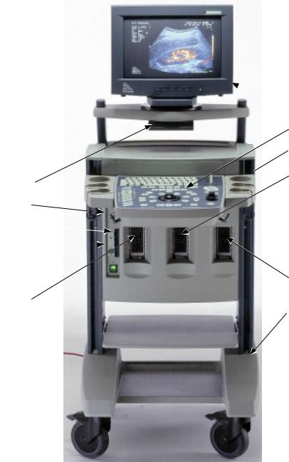
2.1Front View
 1.
1.
2.
3.

 4. 10.
6.
9.
8. 
5.
5.
7.
Identify the following main parts.
1.Monitor
2.Keyboard / TGC / Track Ball
3.Gel bottle holder
4.Array Transducer connector(2102)/"Parking"(2101)
5.Array Transducer connector
6.Single Transducer connector (option)
7.Trolley
8.ECG input (option)
9.Floppy Disk Drive
10.CD-ROM drive (option)
1-4 |
BI2102-D. |

System Falcon 2101/2101EXL & Hawk 2102/2102XDI/2102EXL/Surgical Hawk |
General Information |
2.2Rear Connectors
Monitor Connector
Light pen Connector
Audio In (2102 only)
RGB out Connector
Audio Out (2102 only)
Configuration switch
Foot switch connector
RGB input connector
Doc Trigger output
CBVS out switch (B/W – colour)
RS 232 connector B
CBVS out (B/W – Colour) Connector
5V for PCU(Palm Control unit)
CBVS In Colour Connector
RS 232 connector A
CBVS out Colour Connector
S-VHS out Connector
S-VHS in Connector
2102, 2102XDI
All
Mains Input Fuses Ground connectors
Voltage selector
Light pen Connector Configuration Switch Composite out Connector VCR out Connector VCR in Connector
Monitor Connector
AUX out Power output for monitor 2101
Power output for monitor 2101EXL & 2102
2101
All
RGB out Connector Configuration Switch RGB input Connector
CBVS out switch (B/W – colour) CBVS out (B/W – Colour) Connector CBVS out Colour Connector
CBVS In Colour Connector
S-VHS out Connector
S-VHS in Connector
Light pen Connector
Monitor Connector (VGA)
VGA out Connector
Optional PC Backend: RS232 (MTF option) 5 V Output
12 V Output (CD-ROM drive) LAN Connector (future purposes) Foot switch Connector
Mouse (Trackball) Connector Mover Connector (option)
USB connector (CD-ROM drive)
2101/2102EXL
BI2102-D |
1-5 |
General Information |
System Falcon 2101/2101EXL & Hawk 2102/2102XDI/2102EXL/Surgical Hawk |
2.3System Configuration
The Falcon 2101 and Hawk 2102 exists in the below listed versions:
Falcon 2101 for use in B-, and M-mode.
Falcon 2101 EXL use in B-, and M-mode and additional 3D mode
Hawk 2102 for use in B-, Doppler-, and M-mode.
Hawk 2102 XDI for use in B- (Incl. of True Echo Harmonics), Doppler-, and M-mode.
Hawk 2102 EXL for use in B- (Incl. of True Echo Harmonics), Doppler-, and M-mode and additional 3D mode
Surgical Hawk 2102 XDI for use in B- (Incl. of True Echo Harmonics), Doppler-, and M- mode equipped with a Rack Docking System , PCU (Palm Control unit), and PIP(Picture In Picture) functionality
Surgical Hawk 2102 EXL for use in B- (Incl. of True Echo Harmonics), Doppler-, and M- mode equipped with a Rack Docking System , PCU (Palm Control unit), and PIP(Picture In Picture) functionality and additional 3D mode
2.4Configuration Upgrade
The following upgrade kits are available:
Valid for all models:
•UA1254-K – ECG module upgrade kit
•UA1255-K – Single Input module for mechanical transducers
•UA1270-K – Palm Control Unit Kit for scanners delivered before April 2001
Hawk 2102:
•UA1275-K - Harmonic upgrade kit, valid for Hawk 2102 s/n 1824377 or higher
Hawk 2102XDI:
•UA1276-K – PIP upgrade kit, valid for Hawk 2102XDI
Hawk 2102EXL:
•UA1290 PIP upgrade kit, valid for Hawk 2102EXL
1-6 |
BI2102-D. |

System Falcon 2101/2101EXL & Hawk 2102/2102XDI/2102EXL/Surgical Hawk |
General Information |
2.5Modules and PC Boards
|
Model |
2101 |
2101EXL |
2102 |
2102XDI |
Surgical |
2102EXL & |
Board/ |
|
|
|
|
Hawk |
Surgical |
|
subassembly |
|
|
|
|
2102XDI |
2102EXL |
|
Monitor |
ZV0049 |
ZV0065 |
ZV0050/512 |
ZV0060 |
ZV0060 |
ZV0065 |
|
Video Converter/Mixer board |
|
ZH0743 |
ZH0691 |
ZH0691 |
ZH0699 |
ZH0743 |
|
Video Connector board |
|
ZH0745 |
ZH0692 |
ZH0692 |
ZH0722 |
ZH0745 |
|
VGA connector board |
|
ZH0744 |
|
|
|
ZH0744 |
|
Core board |
ZD0753 |
ZD0771 |
ZD0762/673 |
ZD0762/673 |
ZD0762/673 |
ZD0767 |
|
Front-end board |
ZE0731 |
ZE0731 |
ZE0724 |
ZE0724 |
ZE0724 |
ZE0724 |
|
Delay board |
ZE0726 |
ZE0774 |
ZE0725 |
ZE0768 |
ZE0768 |
ZE0772 |
|
Doppler board |
|
|
ZD0758 |
ZD0758 |
ZD0758 |
ZD0758 |
|
Motherboard |
ZH0675/95 |
ZH0675/95 |
ZH0695 |
ZH0695 |
ZH0695 |
ZH0695 |
|
Power supply |
ZG0341 |
ZG0341/48 |
ZG0341 |
ZG0341 |
ZG0341 |
ZG0341/48 |
|
Keyboard assembly |
ZN0006 |
ZN0006 |
ZN0009 |
ZN0009 |
ZN0009 |
ZN0009 |
|
- |
Potentiometer Board |
ZH0676 |
ZH0676 |
ZH0676 |
ZH0676 |
ZH0676 |
ZH0676 |
- |
Gain Board |
ZH0678 |
ZH0678 |
ZH0678 |
ZH0678 |
ZH0678 |
ZH0678 |
- |
Tracker Ball |
NT0254 |
NT0254 |
NT0254 |
NT0254 |
NT0254 |
NT0254 |
Floppy Drive |
UL0018 |
UL0018 |
UL0018 |
UL0018 |
UL0018 |
UL0018 |
|
ECG Module (UA1254 Option) |
ZE0762 |
ZE0762 |
ZE0762 |
ZE0762 |
ZE0762 |
ZE0762 |
|
Single Module (UA1255 Option) |
ZH0709 |
ZH0709 |
ZH0709 |
ZH0709 |
ZH0709 |
ZH0709 |
|
|
|
|
|
|
|
|
|
PC-Backend (6503 Option) |
N/A |
ZN0377 |
N/A |
N/A |
N/A |
ZN0377 |
|
- |
Single board PC |
N/A |
ZN0042 |
N/A |
N/A |
N/A |
ZN0042 |
- Frame grabber with connect. |
N/A |
ZN0043 |
N/A |
N/A |
N/A |
ZN0043 |
|
- |
Harddisk |
N/A |
UL0023 |
N/A |
N/A |
N/A |
UL0023 |
- |
Power supply |
N/A |
ZG0345 |
N/A |
N/A |
N/A |
ZG0345 |
- |
Connection board |
N/A |
ZH0751 |
N/A |
N/A |
N/A |
ZH0751 |
- |
MCM base |
N/A |
ZH0752 |
N/A |
N/A |
N/A |
ZH0752 |
- MCM Motor Control (option) |
N/A |
ZH0753 |
N/A |
N/A |
N/A |
ZH0753 |
|
- |
CD/RW |
N/A |
ZN0041 |
N/A |
N/A |
N/A |
ZN0041 |
- |
Trackball for PC-Backend |
N/A |
NT0262 |
N/A |
N/A |
N/A |
NT0262 |
- |
Footswitch for PC-Backend |
N/A |
UA1215 |
N/A |
N/A |
N/A |
UA1215 |
2ZV0050=10” / ZV0051=12”
3ZD0762-sw. < 3.00 / ZD0767 sw. ≥ 3.00
BI2102-D |
1-7 |
General Information |
System Falcon 2101/2101EXL & Hawk 2102/2102XDI/2102EXL/Surgical Hawk |
3 Revision System
All PC Boards in the 2101/2102 are described by the board name, Type number, Revision code (ID) and PCB Version.
The name of the board indicates the function of the board, for example the Delay Board. The name of the board is changed only if the function of the board changes.
Part number
Serial Number
Revision level in this case: E
| | | || | |
| ||| | | | |
| | ||| |
| ||| | |
ZD0753 |
001 837 |
B-K Medical A/S |
|
ABCDEFGHIJKLMNOPQRSTUVXY |
Bar Code Label
The Part number of the board, for example ZD0753, is the order number of the board. The number is changed if the modification of the existing PCB is found to be too extensive.
The serial number of the board is a unique number used for tracking purposes.
The revision code (ABCDEFGH.......) is related to the modifications made on the board. The revision letter is marked when modifications are made. When boards are ordered from the B-K Medical stock it is important that the serial number of the scanner is stated. The serial number ensures that the correct revision is shipped.
The PCB version (number e.g. 3) is printed on the circuit board.
Information about Hardware/ Software compatibility can be found in the B-K Medical Hot Line on the support section of www.bkmed.com (requires password)
1-8 |
BI2102-D. |
System Falcon 2101/2101EXL & Hawk 2102/2102XDI/2102EXL/Surgical Hawk |
General Information |
4 Special Tools and Equipment
The tools and equipment listed below does not include standard tools and commonly used equipment.
4.1Checking Procedure (Section 3)
•Transducer Phantom, model 254 (WQ 0973) for checking a 2101/2102 system equipped with Arrayand Single-element Transducers.
•Transducer Phantom, type 251 (WQ 0972) for checking a 2101/2102 system equipped with the Endosonic Probe 1850.
•Ruler (for checking the size of the image on the monitor)
•Floppy disk 3.5" (for testing the floppy disk drive)
•Blank CD-R (for testing PC Back-end CD Drive – option)
Further it is recommended to bring a 150 ml bottle containing preserving fluid for the phantom(s):
Prescription for preserving fluid:
94 ml Glycerol (85%)
50 ml Rodalon (10%)
1000 ml purified Water
BI2102-D |
1-9 |
General Information |
System Falcon 2101/2101EXL & Hawk 2102/2102XDI/2102EXL/Surgical Hawk |
4.2Troubleshooting (Section 4)
For troubleshooting the power supply
•DVM
4.3Adjustment Procedure (Section 5)
For adjusting the monitor:
•Nonmagnetic screwdriver
•Ruler (for checking the size of the image on the monitor)
•Colour Analyser (for 2102 and 2101EXL monitor) For adjusting the monitor friction:
•4 mm Allen key
4.4Mechanical Parts (Section 6)
•Static Control Service Kit, type 3M 8501 (WQ 0969) or similar. (when handling the static sensitive PCB’s).
•TORX key size 10 and 20. A short TORX key size 20 is necessary in order to get easy access to some screws on the monitor assembly.
•Wrench key for Video converter mounted on the Core Board or CD ROM drive for PC Back-end
4.5Preventative Maintenance (Section 7)
•Equipment necessary to perform the Preventative Maintenance is the equipment used in the Checking Procedure and Electrical Safety Test.
4.6Electrical Safety Test
Testers required:
•Safety Tester
•HV Tester
•WB 1275 HV test adaptor for type BF Transducers
High Voltage test plugs required:
•WJ 0246 HV Test Plug for Mains
•WJ 0287 HV Test Plug for ECG (for testing ECG Input Module)
•Electrical Safety Test Record (Enclosed)
1-10 |
BI2102-D. |

2101/2102 Electrical Safety Test Record
Equipment under test |
Serial no: |
Location: |
|
|
|
For INSTRUCTIONS read the back of this sheet.
|
|
|
|
Test Date |
|
|
|
|||
|
|
|
|
|
|
|
|
|
|
|
Test |
Test |
|
|
|
|
|
|
|
Typical |
Test Limits |
Select |
|
|
|
|
|
|
|
|
value |
|
1 |
Rigel self test |
- |
|
|
|
|
|
- |
- |
|
2 |
Mains |
- |
|
|
|
|
|
- |
Nominal +/- |
|
|
Voltage |
|
|
|
|
|
|
|
|
10% |
3 |
Insulation |
Mains to Case |
|
|
|
|
|
|
|
5 MΩ |
Resistance |
|
|
|
|
|
|
|
|
||
|
|
|
|
|
|
|
|
|
|
|
5 |
Pr. gnd |
Console |
|
|
|
|
|
0,1 |
0,2 ohm |
|
(earth terminal) |
|
|
|
|
|
|
ohm |
|||
|
|
|
|
|
|
|
|
|
||
5 |
Pr. gnd |
Transducer |
|
|
|
|
|
0,1 |
0,2 ohm |
|
connector –array |
|
|
|
|
|
|
ohm |
|
||
5 |
Pr. gnd |
Video shelf |
|
|
|
|
|
0,1 |
0,2 ohm |
|
|
|
|
|
|
|
|
|
|
ohm |
|
5 |
Pr. gnd |
Single module |
|
|
|
|
|
0,1 |
0,2 ohm |
|
|
|
connector |
|
|
|
|
|
|
ohm |
|
5 |
Pr. gnd |
Monitor |
|
|
|
|
|
0,1 |
0,2 ohm |
|
|
|
|
|
|
|
|
|
|
ohm |
|
5 |
Pr. gnd |
ECG |
|
|
|
|
|
0,1 |
0,2 ohm |
|
|
|
(Potentiometer button) |
|
|
|
|
|
|
ohm |
|
6 |
Earth |
Norm. |
|
|
|
|
|
|
40 µA |
500 µA |
|
Leakage |
|
|
|
|
|
|
|
|
|
6 |
Earth |
Rev. |
|
|
|
|
|
|
80 µA |
500 µA |
|
Leakage |
|
|
|
|
|
|
|
|
|
7 |
Earth |
Norm. |
|
|
|
|
|
|
2 µA |
1000 µA |
|
Leakage |
|
|
|
|
|
|
|
|
|
7 |
Earth |
Rev. |
|
|
|
|
|
|
120 µA |
1000 µA |
|
Leakage |
|
|
|
|
|
|
|
|
|
8 |
Enclosure |
Norm. |
|
|
|
|
|
|
|
100 µA |
|
Leakage |
|
|
|
|
|
|
|
|
|
8 |
Enclosure |
Rev. |
|
|
|
|
|
|
|
100 µA |
|
Leakage |
|
|
|
|
|
|
|
|
|
11 |
Patient |
Norm. |
|
|
|
|
|
|
|
100 µA |
|
Leakage |
|
|
|
|
|
|
|
|
|
11 |
Patient |
Rev. |
|
|
|
|
|
|
|
100 µA |
|
Leakage |
|
|
|
|
|
|
|
|
|
A |
2.2 kV (DC) |
Mains |
|
|
|
|
|
|
|
No Flash over |
B |
2.2 kV (DC) |
ECG |
|
|
|
|
|
|
|
No Flash over |
|
|
Signature |
|
|
|
|
|
|
|
|
|
|
|
|
|
|
|
|
|
|
1 of 2 |
The test complies with IEC 60601-1 regulations for medical equipment, safety class I, Type B (ECG type BF).
Important:
High Voltage testers deliver hazardous currents. Therefore these testers should only be operated by technicians who are aware of the hazards involved.
Disconnect transducers and accessories from the equipment under test. Test limits are valid only for the equipment itself without any applied part(s) connected.
The complete test must always follow immediately after a repair made on the 2101/2102 Ultrasound Scanner, and always on the fully assembled unit.
Protective GND: General remarks and settings for Test no. 5:
Tester: |
Rigel 233 |
Cables: |
Mains cable for scanner; clip/probe lead (Rigel accessories) |
Basic settings: |
2101/2102 mains switch ON; Rigel switch settings: Class=I, Type: B (For ECG test type BF) |
Calibrate Rigel: |
Connect clip/probe lead between PROBE and GND in IUT POWER socket; Press TEST and zero ohm-meter. |
Connect the scanners Main cable from IUT POWER (Rigel) to power inlet on the scanner.
1. |
Connect the clip/probe lead between PROBE (Rigel) and the left GND connector on the back of the scanner. |
|
Press the TEST button and record the resistance. Disconnect the power cable for the monitor. |
Note: |
As the test current is 25 Amps. it is important that the clip/probe lead is held firmly against, or clipped to the GND |
|
connector before the TEST button is pressed ! |
2. |
Move the clip/probe to the metal on one of the array transducer connectors. Press the TEST button and record the |
|
resistance. |
3. |
Move the clip/probe to on of the metal screws holding the video shelf on the scanner. Press the TEST button and |
|
record the resistance. |
4. |
If single module installed: Move the clip/probe to the metal ring on the single module connector (if installed). Press |
|
the TEST button and record the resistance. |
5. |
Move the clip/probe to on of the metal on the back of the monitor. Press the TEST button and record the resistance. |
6. |
If ECG installed: Set the Rigel tester to type BF. Remove the top on one of the potentiometer buttons on the ECG |
|
module. Move the clip/probe to the nut on the potentiometer button. Press the TEST button and record the |
|
resistance. Set the Rigel tester to type B again. |
Leakage Current: General remarks and settings for test no. 6 and 7.
Test 6 measures Earth Leakage current – normal condition
Test 7 measures Earth Leakage current – single Fault Condition (supply open)
Tester: |
Rigel 233 |
Cables: |
Mains cable for scanner; |
Basic settings: |
2101/2102 mains switch ON; Rigel switch settings: Class = I, Type: B, |
1. |
Connect the mains cable for the scanner to the IUT POWER outlet (Rigel) to power inlet on the scanner |
2. |
Position the Rigel Normal-Reverse switch in Normal and record the current. |
3. |
Position the Rigel Normal-Reverse switch in Reverse and record the current. |
4. |
Repeat the above test for test no. 7. |
High Voltage Test: General remarks and settings for A and B |
|
Tester: |
HV Insulation Tester JP15 |
Cables: |
HV probe and GND lead (JP15 accessories) |
Adaptors: |
HV test plug for mains WJ0246, HV test plug for ECG Module WJ0287 |
Connections: |
Insert the HV test plug for mains into socket for mains input, and HV test plug for ECG Module into ECG |
|
socket. Connect the JP15 GND with the scanners BNC GND using the JP15 GND lead. |
Basic settings: |
Mains switch on scanner ON; on JP15: Connect HV probe cable with switch plug into socket "HT"/"sw". Select |
|
1 A and 7,5 kV. "Volume" to mid position and HV potentiometer fully anti-clockwise. |
Test A: |
Insert tip of HV probe into the HV test plug for mains. Press button on HV probe handle while increasing the HV to |
|
2.2 kV (DC) read from the voltmeter. Apply this voltage for maximum 5 sec. There must be no flash over nor |
|
breakdowns indicated by full deflection on the A-meter. |
Test B: |
Insert tip of HV probe into HV test plug for ECG Module and repeat above test. |
2 of 2
System Falcon 2101/2101EXL & Hawk 2102/2102XDI/2102EXL/Surgical Hawk |
Service Notes |
Section 2
SERVICE NOTES
Service Notes
To improve the performance of the Falcon and Hawk Ultrasound System 2101/2102, small changes in the hardware and firmware may be made. All information about these changes, and any other change or correction to this Service Manual will be released in the form of Service Notes in the Medical Hotline.
Note
All existing and future Service Notes concerning the 2101 Falcon or 2102 Hawk system should be placed in this section.
Edition Number
If any major changes are made to the 2101 Falcon or 2102 Hawk system and/or the
Service Manual, a new edition will be released.
Any new editions can be recognized by the edition number given in the footer.
The serial numbers from which each edition is valid are listed on the front page.
BI2102-D |
2-1 |
Service Notes |
System Falcon 2101/2101EXL & Hawk 2102/2102XDI/2102EXL/Surgical Hawk |
This page is left blank intentionally
2-2 |
BI2102-D |
System Falcon 2101/2101EXL & Hawk 2102/2102XDI/2102EXL/Surgical Hawk |
Checking Procedure |
Section 3 |
|
CHECKING PROCEDURE
CONTENTS |
PAGE |
||
3.1 |
Introduction ................................................................................................................................................... |
2 |
|
3.1.1. |
|
Necessary Equipment to Perform the Checking Procedure............................................................... |
2 |
3.2. |
Basic Checks ................................................................................................................................................ |
2 |
|
3.2.1. |
|
Visual Inspection ................................................................................................................................. |
2 |
3.2.2. |
|
Monitor................................................................................................................................................ |
3 |
3.2.3. |
|
Before Power Up ................................................................................................................................ |
3 |
3.2.4. |
|
Power Up ............................................................................................................................................ |
4 |
3.2.5. |
|
Test Oscillators................................................................................................................................... |
5 |
3.3. |
Monitor Checking....................................................................................................................................... |
14 |
|
3.4. |
Transducer Inputs...................................................................................................................................... |
14 |
|
3.5. |
Track Ball .................................................................................................................................................... |
15 |
|
3.6. |
Gain/TGC..................................................................................................................................................... |
15 |
|
3.7. |
Size............................................................................................................................................................... |
15 |
|
3.8. |
Focusing...................................................................................................................................................... |
16 |
|
3.9. |
Frame Rate.................................................................................................................................................. |
16 |
|
3.10. |
|
Image Processing................................................................................................................................... |
16 |
3.11. |
|
Persistence.............................................................................................................................................. |
16 |
3.12. |
|
Puncture .................................................................................................................................................. |
16 |
3.13. |
|
Zoom ........................................................................................................................................................ |
16 |
3.14. |
|
Measure ................................................................................................................................................... |
17 |
3.15. |
|
Image review ........................................................................................................................................... |
17 |
3.16. |
|
M-mode.................................................................................................................................................... |
17 |
3.17. |
|
Split Screen............................................................................................................................................. |
17 |
3.18. |
|
Image Storage......................................................................................................................................... |
17 |
3.19. |
|
Audio/Spectral Doppler (only 2102) ..................................................................................................... |
18 |
3.20. |
|
CFM (only 2102)...................................................................................................................................... |
18 |
3.21. |
|
PIP (only for 2102 with the PIP option)................................................................................................ |
19 |
3.22. |
|
3D system (6503 option)........................................................................................................................ |
20 |
3.22.1. Basic check – start up & signal transfer to/from scanner ................................................................. |
20 |
||
3.22.2. |
Acquisition ........................................................................................................................................ |
20 |
|
3.22.3. |
CD-RW drive .................................................................................................................................... |
21 |
|
3.22.4. |
ECRM option .................................................................................................................................... |
22 |
|
3.22.5. |
Pull back option ................................................................................................................................ |
23 |
|
3.22.6. |
2050 3D scanning............................................................................................................................. |
23 |
|
3.22.7. |
MTF (Magnetic Tracked Freehand) option....................................................................................... |
24 |
|
BI2102-D |
3-1 |
Checking Procedure |
System Falcon 2101/2101EXL & Hawk 2102/2102XDI/2102EXL/Surgical Hawk |
3.1.Introduction
The Checking Procedure is to verify proper operation of the main functions of the 2101/2102 System.
The procedure should be used during installation, incoming inspection, regular maintenance and before and after repair.
The procedure is arranged in sections and must be followed from the beginning when performed.
Notes
If the Checking Procedure cannot be performed successfully or if there is a specific fault in the System, refer to Section 4, TROUBLESHOOTING or Section 5, ADJUSTMENT PROCEDURE.
The Checking Procedure does not include a check of the different transducer types.
If in doubt about the functions of the 2101/2101EXL/2102/2102XDI/2102EXL you should consult the user guide BB0340/BB1086/BB0360/BB0950/BB1075.
Important!!
Any inside repairs performed on the 2101/2102 must be followed by an Electrical Safety
Test.
3.1.1.Necessary Equipment to Perform the Checking Procedure
•Transducer Phantom, model 254 (WQ 0973) for checking a 2101/2102 system equipped with Arrayand Single-element Transducers.
•Transducer Phantom, type 251 (WQ 0972) for checking a 2101/2102 system equipped with the Endosonic Probe 1850.
•Ruler (for checking the size of the image on the monitor)
•Floppy disk 3.5" (for testing the floppy disk drive)
•Array Transducer (Linear or Convex).
•Sector Transducer (for systems equipped with Single-element module)
Note: If a phantom is not available the human body is a good alternative.
3.2.Basic Checks
3.2.1.Visual Inspection
1.Check the overall appearance of the 21/012102.
Especially check for scratches and stain's on the paint.
3-2 |
BI2102-D |
System Falcon 2101/2101EXL & Hawk 2102/2102XDI/2102EXL/Surgical Hawk |
Checking Procedure |
3.2.2.Monitor
1.Check that the monitor is securely fastened on its base and is easy to rotate.
3.2.3.Before Power Up
1.Check that the two voltage selector switches found on the rear panel of the Power Supply are set for the actual mains voltage.
2.Check the rating of the primary fuses:
If 230 V AC: |
T 6.3 A H, 250V (Time lag high breaking capacity) |
If 115 V AC: |
T 8 A H, 250V (Time lag high breaking capacity) |
3.The 2101/2102 System complies with the IEC 60601-1 safety regulations and as such it must be connected to a mains outlet having a safety ground connection. Therefore: Check that the 2101/2102 mains cable is terminated with a three-pole plug that fits a three-pole mains outlet. For safety reasons do not use extension cables!
BI2102-D |
3-3 |

Checking Procedure |
System Falcon 2101/2101EXL & Hawk 2102/2102XDI/2102EXL/Surgical Hawk |
3.2.4.Power Up
1.Disconnect all accessories from the 2101/2102 and connect any transducer available which fits the Array Input Module.
2.Switch On the 201/2102.
After a few moments the power up (boot) sequence is completed.
3.Verify that the monitor opening layouts are shown in Fig. 3.3 -1. Note that the menu shown (settings) differs from transducer type.
Fig. 3.3-1. The default display.
4.Check that the following is displayed on the monitor:
•the current date and time
•a white “Asteric” (“Freeze”-mode)
Note: If the displayed date and time is incorrect, press Setup to display the Setup menu.
Press F2 to display the Date /Time menu and use the track ball to go to the
field to adjust. Press  to toggle the menu’s. Press F1 for Next Page
To exit the menu press Setup.
3-4 |
BI2102-D |
System Falcon 2101/2101EXL & Hawk 2102/2102XDI/2102EXL/Surgical Hawk |
Checking Procedure |
3.2.5.Test Oscillators
1.Connect an electronic transducer to the 2101/2102.
2.Switch On the scanner.
3.Press Shift, Alt and  to select the Test menu
4.Select the Scancon Test oscillator by pressing F3 and unfreeze
Toggle between Scancon test 1,2 and 3 by pressing F3, and compare to the images below. To bring up the test menu again, press Shift, Alt and  Note that the actual image on the scanner depends on various settings e.g. size and transducer type.
Fig. 3.3-2. Scancon Test Osc. 1 and 2. Check that image is going from black to white
Fig. 3.3-3. Scancon Test Oscillator 3 - Greyscale horizontally.
Note ! this image might flicker dependable on transducer type and size of image
BI2102-D |
3-5 |
Checking Procedure |
System Falcon 2101/2101EXL & Hawk 2102/2102XDI/2102EXL/Surgical Hawk |
5.Exit the Scancon Test by keeping F3 depressed for 1 second.
6.Select the Input Test Oscillator by pressing F1. Compare to the image below.
Fig. 3.3-4. Input Test Oscillator.
7.Exit the Input Test Oscillator by pressing F1.
3-6 |
BI2102-D |

System Falcon 2101/2101EXL & Hawk 2102/2102XDI/2102EXL/Surgical Hawk |
Checking Procedure |
8.Switch off the scanner and disconnect all transducers from the 2101/2102.
9.Turn on the scanner and after the boot sequence press Shift, Alt and  .
.
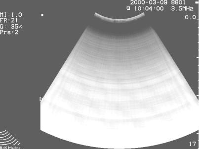
10.Select the Delay Test oscillator by pressing F2 and unfreeze The image should now look like the figure below i.e. concentric bands which gradually goes from black to white (light grey) and then back to black.
Note ! The actual number of concentric bands depends on the size selected.
Fig. 3.3-5. Delay Test Oscillator 1
BI2102-D |
3-7 |

Checking Procedure |
System Falcon 2101/2101EXL & Hawk 2102/2102XDI/2102EXL/Surgical Hawk |
11.Press Shift, Alt and  to access the Test Oscillator again.
12.Press F2 to start Delay test oscillator 2. The image should now look like the figure below i.e. 6/8 concentric bands which consist of a number of white (light grey)blocks separated by 48/64 narrow black radial lines.
Note ! If bands are missing from the sides it could be because of the user setup. In that case make a backup of the 8802 set-up on a floppy disk and reset the 8802 set-up. Remember to load the customer setup again after the test.
Fig. 3.3-6. Delay Test Oscillator 2 on 2101
Fig. 3.3-7. Delay Test Oscillator 2 on 2102
3-8 |
BI2102-D |

System Falcon 2101/2101EXL & Hawk 2102/2102XDI/2102EXL/Surgical Hawk |
Checking Procedure |
13.Turn the gain down to see if all bands can be adjusted to dark grey and turn the gain up again to see if the bands appears white again.
Fig. 3.3-8. Delay Test Oscillator 2 with gain turned down – test image should fade out
.
BI2102-D |
3-9 |
Checking Procedure |
System Falcon 2101/2101EXL & Hawk 2102/2102XDI/2102EXL/Surgical Hawk |
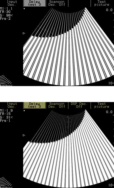
14.Press F2 to start Delay test oscillator 3. The image should now look like the figure below i.e. 24/32 radial fields separated by narrow white lines. The fields should be white from top to bottom and then gradual decrease in length going from right to left.
Note ! On 2101 the left line should be a narrow line where as on the 2102 it should be a wide field.
Fig. 3.3-9. Delay Test Oscillator 3 (2101).
Fig. 3.3-10. Delay Test Oscillator 3 (2102).
15.Turn the gain down to see if all bands can be adjusted to dark grey and turn the gain up again to see if the bands appears white again.
16.Switch off the scanner
3-10 |
BI2102-D |

|
System Falcon 2101/2101EXL & Hawk 2102/2102XDI/2102EXL/Surgical Hawk |
Checking Procedure |
||
2102 Only ! |
17. |
Connect an electronic transducer to the 2102 and switch on the scanner. |
||
(for 2101 continue |
18. |
Press CFM |
|
|
with step 24) |
|
|||
19. |
Select the test menu by pressing Press Shift, Alt and . |
|
||
|
|
|
||
|
|
20. |
Select DSP osc. by pressing F4 and then press Freeze and compare to the |
|
|
|
|
figure below. |
|
Fig. 3.3-11. Doppler test Oscillator 1.
BI2102-D |
3-11 |

Checking Procedure |
System Falcon 2101/2101EXL & Hawk 2102/2102XDI/2102EXL/Surgical Hawk |
21.Press Shift, Alt and  to activate the Test menu.
22.Press F4 to activate Test oscillator Disp. Osc.2
23.Press Freeze twice (freeze and then unfreeze) and compare to the Figure below.
Fig. 3.3-12. Doppler test Oscillator 2.
3-12 |
BI2102-D |

System Falcon 2101/2101EXL & Hawk 2102/2102XDI/2102EXL/Surgical Hawk |
Checking Procedure |
24.If the 2101/2102 has a single input module then switch off the scanner and disconnect all transducers from the 2101/2102.
25.Turn on the scanner.
26.Start the Single Input Test Oscillator by pressing Shift, Alt, and Z, select e.g. 8539 (F2) and unfreeze. Compare to the image below.
Fig. 3.3-13. Single Input Test Oscillator.
27.Exit the Single Input oscillator by pressing Shift, Alt, and Z.
28.If the 2101/2102 has an ECG option then connect a transducer and unfreeze the image.
29.Press S (HR) to get the ECG Curve on the screen.
30.Select the ECG test by pressing Shift, Alt, S. Compare to the image below. Note ! The amplitude and position of test curve depends of the setting of the ECG potentiometers.)
Fig. 3.3-14. ECG Test Oscillator
BI2102-D |
3-13 |

Checking Procedure |
System Falcon 2101/2101EXL & Hawk 2102/2102XDI/2102EXL/Surgical Hawk |
3.3.Monitor Checking
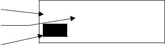
Press Shift, Alt, and G, to get a test picture on the monitor screen (The scanner must be in freeze mode).
1.One for brightness with two dark squares where one is 2/255 and the other is 4/255 of 100% white,
Brightness is adjusted so the 2/255 part disappear and the 4/255 is just become visible.
2.One for contrast with one square filled out white 100% white (255/255). Contrast has to be adjusted to 60 cd/m2 measured in the centre of the square
3.Test picture displaying a linear 8 step greyscale for final check of monitor adjustment
Use <Alt><Shift><G> to toggle through the test pictures. 1.
2.Verify that the external controls for Brightness and Contrast (on the monitor) provides sufficient adjustment range and set to give the best image.
3.Press the Shift, Alt and  . Then press F5 to chose the Test picture. (Pressing F5 toggles between Geometric test picture, all pixel off, all pixels on)
2101-197 mm
2102 -10”:176mm, 12”:189mm, 14”:221mm 15:228mm
2101: 149 mm –10”:133mm, 12”:143mm, |
14”:167mm 15”:171mm |
2102 |
|
Fig. 3.3-15. The Geometric Test Picture..
4.Check the geometry of the test Picture.
5.If you have problems meeting the above requirements, consult Section 5, ADJUSTMENT PROCEDURE.
3.4.Transducer Inputs
1. |
Move the transducer connector to the other input module(s), Press |
and |
|
confirm that the transducer can be identified. |
|
2.Start the transducer to verify correct operation of the input module.
Note: |
If available connect a Single-element transducer to the Single element socket |
|
and verify correct operation of the transducer. |
3-14 |
BI2102-D |
Loading...