

Page 1
Pro Focus 2202
Extended User Guide
English
BB1279-A
June 2005
Page 2

•
NOT FAULT TOLERANT
HAS INDEPENDENTLY DETERMINED HOW TO USE THE SOFTWARE IN THE DEVICE,
AND MS HAS RELIED UPON B-K Medical TO CONDUCT SUFFICIENT TESTING TO
DETERMINE THAT THE SOFTWARE IS SUITABLE FOR USE.
•
EXPORT RESTRICTIONS
You agree to comply with all applicable international and national laws that apply to Windo ws XP
Embedded, including the U.S. Export Administration Regulations, as well as end-user, end-use and
country destination restrictions issued by U.S. and other governments. For additional information
on exporting Wi ndows XP Embedded, see http://www.microsoft.com/exporting/
•
The Pro Focus 2202 Ultrasound Scanner is closed. Any modification of or installation of software
to the system may compromise safety and function of the system. Any modification of or
installation of software without written permission from B-K Medical will immediately void any
warranty supplied by B-K Medical. Such changes will also void any service contract and result in
charges to the customer for restoration of the original Pro Focus 2202 system.
Trademarks:
DICOM is the registered trademark of the National Electrical Manufacturers Association for its
standards publications relating to digital communications of medical information.
TEH and Pro Package are trademarks of B-K Medical.
Microsoft and Windows are re gistered trademarks of Microsoft Corporation in the United States and
other countries.
SonoVue is a registered trademark of Bracco S.p.A.
FireWire is a trademark of Apple Computer, Inc.
CIV-Flex is a trademark of CIVCO Medical Instruments Co., Inc.
. THE SOFTWARE IS NOT FAULT TOLERANT. B-K Medical
. You acknowledge that Windows XP Embedded is of US-origin.
WORLD HEADQUARTERS
Mileparken 34
DK-2730 Herlev
Tel.:+45 44528100
Fax:+45 44528199
Website: www.bkmed.com
© 2005 B-K Medical
Information in this document may be subject to change without notice.
Page 3

Contents
Part 1 Basics
Chapter 1 General and Safety Information . . . . . . . . . . . . . . . . . . . . . . . . . . . . . . . . . . . . . . 17
About this User Guide. . . . . . . . . . . . . . . . . . . . . . . . . . . . . . . . . . . . . . . . . . 17
Safety Information . . . . . . . . . . . . . . . . . . . . . . . . . . . . . . . . . . . . . . . . . 18
Typographical Conventions. . . . . . . . . . . . . . . . . . . . . . . . . . . . . . . . . . 18
Terminology. . . . . . . . . . . . . . . . . . . . . . . . . . . . . . . . . . . . . . . . . . . . . . 18
About the Scanner. . . . . . . . . . . . . . . . . . . . . . . . . . . . . . . . . . . . . . . . . . . . . 19
Scanning Modes. . . . . . . . . . . . . . . . . . . . . . . . . . . . . . . . . . . . . . . . . . . 19
Pro Packages . . . . . . . . . . . . . . . . . . . . . . . . . . . . . . . . . . . . . . . . . . . . . 19
Safety Symbols on the Scanner . . . . . . . . . . . . . . . . . . . . . . . . . . . . . . . 19
CE Marks on Electrical Devices . . . . . . . . . . . . . . . . . . . . . . . . . . . . . . . . . . 21
General Safety Precautions . . . . . . . . . . . . . . . . . . . . . . . . . . . . . . . . . . . . . . 21
Explosion Hazards . . . . . . . . . . . . . . . . . . . . . . . . . . . . . . . . . . . . . . . . . 22
Electrical Safety . . . . . . . . . . . . . . . . . . . . . . . . . . . . . . . . . . . . . . . . . . . 22
Interference . . . . . . . . . . . . . . . . . . . . . . . . . . . . . . . . . . . . . . . . . . . . . . 23
Installation . . . . . . . . . . . . . . . . . . . . . . . . . . . . . . . . . . . . . . . . . . . . . . . 24
Transducers . . . . . . . . . . . . . . . . . . . . . . . . . . . . . . . . . . . . . . . . . . . . . . 24
Other Safety Considerations . . . . . . . . . . . . . . . . . . . . . . . . . . . . . . . . . 24
Service and Repair . . . . . . . . . . . . . . . . . . . . . . . . . . . . . . . . . . . . . . . . . 25
Connecting Other Equipment. . . . . . . . . . . . . . . . . . . . . . . . . . . . . . . . . 25
Computer Security . . . . . . . . . . . . . . . . . . . . . . . . . . . . . . . . . . . . . . . . . . . . 26
Acoustic Output . . . . . . . . . . . . . . . . . . . . . . . . . . . . . . . . . . . . . . . . . . . . . . 26
General. . . . . . . . . . . . . . . . . . . . . . . . . . . . . . . . . . . . . . . . . . . . . . . . . . 26
Monitor Display . . . . . . . . . . . . . . . . . . . . . . . . . . . . . . . . . . . . . . . . . . . 28
Thermal and Mechanical Indices . . . . . . . . . . . . . . . . . . . . . . . . . . . . . . 28
Acoustic Output Measurement. . . . . . . . . . . . . . . . . . . . . . . . . . . . . . . . 29
Functions Affecting Acoustic Output . . . . . . . . . . . . . . . . . . . . . . . . . . 29
Default Acoustic Output . . . . . . . . . . . . . . . . . . . . . . . . . . . . . . . . . . . . 30
References. . . . . . . . . . . . . . . . . . . . . . . . . . . . . . . . . . . . . . . . . . . . . . . . . . . 30
Chapter 2 Getting Started . . . . . . . . . . . . . . . . . . . . . . . . . . . . . . . . . . . . . . . . . . . . . . . . . . .33
General Information . . . . . . . . . . . . . . . . . . . . . . . . . . . . . . . . . . . . . . . . . . . 33
Adjusting the Keyboard Panel and Monitor . . . . . . . . . . . . . . . . . . . . . . . . . 34
Turning the Scanner On and Off. . . . . . . . . . . . . . . . . . . . . . . . . . . . . . . . . . 34
Checking the Date. . . . . . . . . . . . . . . . . . . . . . . . . . . . . . . . . . . . . . . . . . . . . 35
Adjusting the Brightness of the Screen. . . . . . . . . . . . . . . . . . . . . . . . . . . . . 35
Adjusting the Reading Lights . . . . . . . . . . . . . . . . . . . . . . . . . . . . . . . . . . . . 35
Setting up a New Patient. . . . . . . . . . . . . . . . . . . . . . . . . . . . . . . . . . . . . . . . 36
Opening the Patient Window. . . . . . . . . . . . . . . . . . . . . . . . . . . . . . . . . 36
Changing Pro Package or Diagnostic Setup in the Patient Window . . . 37
3
Page 4

New Patient Information from a DICOM Worklist . . . . . . . . . . . . . . . . 37
Entering Dates . . . . . . . . . . . . . . . . . . . . . . . . . . . . . . . . . . . . . . . . . . . . 39
Keeping Image Settings . . . . . . . . . . . . . . . . . . . . . . . . . . . . . . . . . . . . . 40
Keeping Patient-Related Data . . . . . . . . . . . . . . . . . . . . . . . . . . . . . . . . 40
Connecting and Selecting Transducers . . . . . . . . . . . . . . . . . . . . . . . . . . . . . 40
Connecting a Transducer . . . . . . . . . . . . . . . . . . . . . . . . . . . . . . . . . . . . 40
Selecting a Transducer . . . . . . . . . . . . . . . . . . . . . . . . . . . . . . . . . . . . . . 41
Selecting the Scanning Plane . . . . . . . . . . . . . . . . . . . . . . . . . . . . . . . . . 42
Pro Packages and Diagnostic Setups. . . . . . . . . . . . . . . . . . . . . . . . . . . . . . . 42
Selecting a Pro Package or Diagnostic Setup. . . . . . . . . . . . . . . . . . . . . 42
Saving a Diagnostic Setup . . . . . . . . . . . . . . . . . . . . . . . . . . . . . . . . . . . 43
Selecting or Changing the Scanning Mode . . . . . . . . . . . . . . . . . . . . . . . . . . 43
Performing a Biopsy or Puncture Procedure (including Brachytherapy) . . . 43
Using the PCU (Palm Control Unit) . . . . . . . . . . . . . . . . . . . . . . . . . . . . . . . 45
Attaching the PCU . . . . . . . . . . . . . . . . . . . . . . . . . . . . . . . . . . . . . . . . . 45
Checking the PCU . . . . . . . . . . . . . . . . . . . . . . . . . . . . . . . . . . . . . . . . . 46
Putting Sterile Covers on the PCU. . . . . . . . . . . . . . . . . . . . . . . . . . . . . 46
References . . . . . . . . . . . . . . . . . . . . . . . . . . . . . . . . . . . . . . . . . . . . . . . . . . . 47
Part 2 Working with the Image
Chapter 3 The User Interface . . . . . . . . . . . . . . . . . . . . . . . . . . . . . . . . . . . . . . . . . . . . . . . . . 51
Keyboard Panel Controls. . . . . . . . . . . . . . . . . . . . . . . . . . . . . . . . . . . . . . . . 51
The Control Panel. . . . . . . . . . . . . . . . . . . . . . . . . . . . . . . . . . . . . . . . . . 52
The Trackball and Trackball Keys . . . . . . . . . . . . . . . . . . . . . . . . . . . . . 53
Basic Keys . . . . . . . . . . . . . . . . . . . . . . . . . . . . . . . . . . . . . . . . . . . . . . . 56
B-Mode Keys . . . . . . . . . . . . . . . . . . . . . . . . . . . . . . . . . . . . . . . . . . . . . 57
B-Mode Adjustment Keys . . . . . . . . . . . . . . . . . . . . . . . . . . . . . . . . . . . 58
Power and Color Mode Keys . . . . . . . . . . . . . . . . . . . . . . . . . . . . . . . . . 59
Doppler and M-Mode Keys . . . . . . . . . . . . . . . . . . . . . . . . . . . . . . . . . . 60
Doppler Adjustment Keys . . . . . . . . . . . . . . . . . . . . . . . . . . . . . . . . . . . 61
User-Defined Keys . . . . . . . . . . . . . . . . . . . . . . . . . . . . . . . . . . . . . . . . . 63
Image Annotation Keys . . . . . . . . . . . . . . . . . . . . . . . . . . . . . . . . . . . . . 64
Miscellaneous Keys . . . . . . . . . . . . . . . . . . . . . . . . . . . . . . . . . . . . . . . . 65
TGC Sliders . . . . . . . . . . . . . . . . . . . . . . . . . . . . . . . . . . . . . . . . . . . . . . 65
Keyboard . . . . . . . . . . . . . . . . . . . . . . . . . . . . . . . . . . . . . . . . . . . . . . . . 66
Controls on the Screen. . . . . . . . . . . . . . . . . . . . . . . . . . . . . . . . . . . . . . . . . . 67
Point and Click . . . . . . . . . . . . . . . . . . . . . . . . . . . . . . . . . . . . . . . . . . . . 68
Foot Switch . . . . . . . . . . . . . . . . . . . . . . . . . . . . . . . . . . . . . . . . . . . . . . . . . . 69
Palm Control Unit (PCU) . . . . . . . . . . . . . . . . . . . . . . . . . . . . . . . . . . . . . . . 70
Transducers . . . . . . . . . . . . . . . . . . . . . . . . . . . . . . . . . . . . . . . . . . . . . . . . . . 72
Chapter 4 Working with the Image . . . . . . . . . . . . . . . . . . . . . . . . . . . . . . . . . . . . . . . . . . . .73
Image Orientation . . . . . . . . . . . . . . . . . . . . . . . . . . . . . . . . . . . . . . . . . . . . . 73
Freezing the Image . . . . . . . . . . . . . . . . . . . . . . . . . . . . . . . . . . . . . . . . . . . . 73
4
Page 5

Update - Partial Freeze . . . . . . . . . . . . . . . . . . . . . . . . . . . . . . . . . . . . . . . . . 73
Split Screen . . . . . . . . . . . . . . . . . . . . . . . . . . . . . . . . . . . . . . . . . . . . . . . . . . 74
Simultaneous Scanning. . . . . . . . . . . . . . . . . . . . . . . . . . . . . . . . . . . . . . 74
Labelling Parts of the Image . . . . . . . . . . . . . . . . . . . . . . . . . . . . . . . . . . . . . 75
Placing Labels. . . . . . . . . . . . . . . . . . . . . . . . . . . . . . . . . . . . . . . . . . . . . 75
Arrows . . . . . . . . . . . . . . . . . . . . . . . . . . . . . . . . . . . . . . . . . . . . . . . . . . 76
Moving Labels and Arrows . . . . . . . . . . . . . . . . . . . . . . . . . . . . . . . . . . 77
Creating and Editing Labels . . . . . . . . . . . . . . . . . . . . . . . . . . . . . . . . . . 77
Removing Labels and Arrows . . . . . . . . . . . . . . . . . . . . . . . . . . . . . . . . 77
Using Bodymarks . . . . . . . . . . . . . . . . . . . . . . . . . . . . . . . . . . . . . . . . . . . . . 78
Adding a Bodymark . . . . . . . . . . . . . . . . . . . . . . . . . . . . . . . . . . . . . . . . 79
Moving a Bodymark. . . . . . . . . . . . . . . . . . . . . . . . . . . . . . . . . . . . . . . . 79
Replacing a Bodymark . . . . . . . . . . . . . . . . . . . . . . . . . . . . . . . . . . . . . . 80
Setting a Default Position for Bodymarks . . . . . . . . . . . . . . . . . . . . . . . 80
Removing a Bodymark. . . . . . . . . . . . . . . . . . . . . . . . . . . . . . . . . . . . . . 80
Adding New Bodymarks . . . . . . . . . . . . . . . . . . . . . . . . . . . . . . . . . . . . 80
Cine . . . . . . . . . . . . . . . . . . . . . . . . . . . . . . . . . . . . . . . . . . . . . . . . . . . . . . . . 80
Using Cine in M-Mode or Doppler Mode . . . . . . . . . . . . . . . . . . . . . . . 81
Cine Play. . . . . . . . . . . . . . . . . . . . . . . . . . . . . . . . . . . . . . . . . . . . . . . . . 82
The Video Window and Picture in Picture (PiP). . . . . . . . . . . . . . . . . . . . . . 82
Using the Video Window . . . . . . . . . . . . . . . . . . . . . . . . . . . . . . . . . . . . 83
Using PiP . . . . . . . . . . . . . . . . . . . . . . . . . . . . . . . . . . . . . . . . . . . . . . . . 84
Chapter 5 Making Measurements . . . . . . . . . . . . . . . . . . . . . . . . . . . . . . . . . . . . . . . . . . . . .87
Measurements and Calculations . . . . . . . . . . . . . . . . . . . . . . . . . . . . . . . . . . 87
Making a Measurement – General Procedure . . . . . . . . . . . . . . . . . . . . 87
Clearing a Measurement. . . . . . . . . . . . . . . . . . . . . . . . . . . . . . . . . . . . . 88
Clearing All Measurements . . . . . . . . . . . . . . . . . . . . . . . . . . . . . . . . . . 88
B-Mode and Color Mode Measuring Tools . . . . . . . . . . . . . . . . . . . . . . 88
Doppler Mode Measuring Tools. . . . . . . . . . . . . . . . . . . . . . . . . . . . . . . 95
Chapter 6 Documentation . . . . . . . . . . . . . . . . . . . . . . . . . . . . . . . . . . . . . . . . . . . . . . . . . . .99
What are documents? . . . . . . . . . . . . . . . . . . . . . . . . . . . . . . . . . . . . . . . . . . 99
Patient Archiving. . . . . . . . . . . . . . . . . . . . . . . . . . . . . . . . . . . . . . . . . . . . . . 99
The Document Browser. . . . . . . . . . . . . . . . . . . . . . . . . . . . . . . . . . . . . . . . 100
Saving Documents . . . . . . . . . . . . . . . . . . . . . . . . . . . . . . . . . . . . . . . . 101
Viewing Documents . . . . . . . . . . . . . . . . . . . . . . . . . . . . . . . . . . . . . . . 102
The Archive Window . . . . . . . . . . . . . . . . . . . . . . . . . . . . . . . . . . . . . . . . . 103
Patient Information. . . . . . . . . . . . . . . . . . . . . . . . . . . . . . . . . . . . . . . . 104
Examination Information . . . . . . . . . . . . . . . . . . . . . . . . . . . . . . . . . . . 106
Patient and Document Comments . . . . . . . . . . . . . . . . . . . . . . . . . . . . 106
Deleting Patients or Documents . . . . . . . . . . . . . . . . . . . . . . . . . . . . . . 106
Externally Stored Documents . . . . . . . . . . . . . . . . . . . . . . . . . . . . . . . . . . . 107
Copying and Archiving Documents . . . . . . . . . . . . . . . . . . . . . . . . . . . . . . 108
Copying and Archiving . . . . . . . . . . . . . . . . . . . . . . . . . . . . . . . . . . . . 108
5
Page 6

Copying Documents. . . . . . . . . . . . . . . . . . . . . . . . . . . . . . . . . . . . . . . 108
Archiving Documents. . . . . . . . . . . . . . . . . . . . . . . . . . . . . . . . . . . . . . 109
Format of Saved Documents . . . . . . . . . . . . . . . . . . . . . . . . . . . . . . . . 109
Using CDs. . . . . . . . . . . . . . . . . . . . . . . . . . . . . . . . . . . . . . . . . . . . . . . 109
Using Flash Memory . . . . . . . . . . . . . . . . . . . . . . . . . . . . . . . . . . . . . . 111
Using the DICOM System . . . . . . . . . . . . . . . . . . . . . . . . . . . . . . . . . . 111
Printing Documents. . . . . . . . . . . . . . . . . . . . . . . . . . . . . . . . . . . . . . . . . . . 113
Printing on a DICOM Printer . . . . . . . . . . . . . . . . . . . . . . . . . . . . . . . . 113
Printing on a Local Printer . . . . . . . . . . . . . . . . . . . . . . . . . . . . . . . . . . 114
Reports. . . . . . . . . . . . . . . . . . . . . . . . . . . . . . . . . . . . . . . . . . . . . . . . . . . . . 114
Displaying a Report . . . . . . . . . . . . . . . . . . . . . . . . . . . . . . . . . . . . . . . 114
Printing a Report. . . . . . . . . . . . . . . . . . . . . . . . . . . . . . . . . . . . . . . . . . 115
Saving a Report to the Patient Archiving System . . . . . . . . . . . . . . . . 115
Password Protection of the Database . . . . . . . . . . . . . . . . . . . . . . . . . . . . . 115
Part 3 Imaging Modes
Chapter 7 B-Mode – 2D Imaging . . . . . . . . . . . . . . . . . . . . . . . . . . . . . . . . . . . . . . . . . . . . .119
Overview . . . . . . . . . . . . . . . . . . . . . . . . . . . . . . . . . . . . . . . . . . . . . . . . . . . 119
Adjusting MI . . . . . . . . . . . . . . . . . . . . . . . . . . . . . . . . . . . . . . . . . . . . . . . . 119
Adjusting the Scan Area . . . . . . . . . . . . . . . . . . . . . . . . . . . . . . . . . . . . . . . 120
Depth . . . . . . . . . . . . . . . . . . . . . . . . . . . . . . . . . . . . . . . . . . . . . . . . . . 120
Width . . . . . . . . . . . . . . . . . . . . . . . . . . . . . . . . . . . . . . . . . . . . . . . . . . 120
Gain . . . . . . . . . . . . . . . . . . . . . . . . . . . . . . . . . . . . . . . . . . . . . . . . . . . 120
Focus. . . . . . . . . . . . . . . . . . . . . . . . . . . . . . . . . . . . . . . . . . . . . . . . . . . 122
Autofocus . . . . . . . . . . . . . . . . . . . . . . . . . . . . . . . . . . . . . . . . . . . . . . . 123
Dynamic Range (Contrast). . . . . . . . . . . . . . . . . . . . . . . . . . . . . . . . . . 123
Zoom. . . . . . . . . . . . . . . . . . . . . . . . . . . . . . . . . . . . . . . . . . . . . . . . . . . 123
Panning. . . . . . . . . . . . . . . . . . . . . . . . . . . . . . . . . . . . . . . . . . . . . . . . . 124
Persistence . . . . . . . . . . . . . . . . . . . . . . . . . . . . . . . . . . . . . . . . . . . . . . 125
Edge Enhancement. . . . . . . . . . . . . . . . . . . . . . . . . . . . . . . . . . . . . . . . 125
Auto . . . . . . . . . . . . . . . . . . . . . . . . . . . . . . . . . . . . . . . . . . . . . . . . . . . 125
Line Density . . . . . . . . . . . . . . . . . . . . . . . . . . . . . . . . . . . . . . . . . . . . . 126
Multibeam. . . . . . . . . . . . . . . . . . . . . . . . . . . . . . . . . . . . . . . . . . . . . . . 126
Resolution. . . . . . . . . . . . . . . . . . . . . . . . . . . . . . . . . . . . . . . . . . . . . . . 126
Extended Resolution. . . . . . . . . . . . . . . . . . . . . . . . . . . . . . . . . . . . . . . 126
B-Mode Frequency – MFI . . . . . . . . . . . . . . . . . . . . . . . . . . . . . . . . . . 127
B-Mode Gray Scale . . . . . . . . . . . . . . . . . . . . . . . . . . . . . . . . . . . . . . . 127
B Color . . . . . . . . . . . . . . . . . . . . . . . . . . . . . . . . . . . . . . . . . . . . . . . . . 127
Combination Modes . . . . . . . . . . . . . . . . . . . . . . . . . . . . . . . . . . . . . . . . . . 128
Harmonic Imaging. . . . . . . . . . . . . . . . . . . . . . . . . . . . . . . . . . . . . . . . . . . . 128
Tissue Harmonic Imaging (True Echo Harmonics – TEH) . . . . . . . . . 128
Timer . . . . . . . . . . . . . . . . . . . . . . . . . . . . . . . . . . . . . . . . . . . . . . . . . . 129
6
Page 7

Chapter 8 M-Mode . . . . . . . . . . . . . . . . . . . . . . . . . . . . . . . . . . . . . . . . . . . . . . . . . . . . . . . . .131
Overview . . . . . . . . . . . . . . . . . . . . . . . . . . . . . . . . . . . . . . . . . . . . . . . . . . . 131
The M-mode image . . . . . . . . . . . . . . . . . . . . . . . . . . . . . . . . . . . . . . . 131
Adjusting the Scan Area . . . . . . . . . . . . . . . . . . . . . . . . . . . . . . . . . . . . . . . 132
M-Mode Line . . . . . . . . . . . . . . . . . . . . . . . . . . . . . . . . . . . . . . . . . . . . 132
M-Mode Image Ruler. . . . . . . . . . . . . . . . . . . . . . . . . . . . . . . . . . . . . . 132
Sweep Speed. . . . . . . . . . . . . . . . . . . . . . . . . . . . . . . . . . . . . . . . . . . . . 132
Gain . . . . . . . . . . . . . . . . . . . . . . . . . . . . . . . . . . . . . . . . . . . . . . . . . . . 132
Focus. . . . . . . . . . . . . . . . . . . . . . . . . . . . . . . . . . . . . . . . . . . . . . . . . . . 133
Autofocus . . . . . . . . . . . . . . . . . . . . . . . . . . . . . . . . . . . . . . . . . . . . . . . 133
Dynamic Range (Contrast). . . . . . . . . . . . . . . . . . . . . . . . . . . . . . . . . . 133
Zoom. . . . . . . . . . . . . . . . . . . . . . . . . . . . . . . . . . . . . . . . . . . . . . . . . . . 134
Panning. . . . . . . . . . . . . . . . . . . . . . . . . . . . . . . . . . . . . . . . . . . . . . . . . 134
Edge Enhancement. . . . . . . . . . . . . . . . . . . . . . . . . . . . . . . . . . . . . . . . 134
M-mode Frequency – MFI . . . . . . . . . . . . . . . . . . . . . . . . . . . . . . . . . . 134
M-Mode Gray Scale . . . . . . . . . . . . . . . . . . . . . . . . . . . . . . . . . . . . . . . 134
Chapter 9 Color Mode – Color Flow Mapping . . . . . . . . . . . . . . . . . . . . . . . . . . . . . . . . . .137
Overview . . . . . . . . . . . . . . . . . . . . . . . . . . . . . . . . . . . . . . . . . . . . . . . . . . . 137
Color Flow Mapping . . . . . . . . . . . . . . . . . . . . . . . . . . . . . . . . . . . . . . . . . . 137
Submodes . . . . . . . . . . . . . . . . . . . . . . . . . . . . . . . . . . . . . . . . . . . . . . . . . . 137
Adjusting the Thermal Index Limit. . . . . . . . . . . . . . . . . . . . . . . . . . . . . . . 138
Adjusting MI . . . . . . . . . . . . . . . . . . . . . . . . . . . . . . . . . . . . . . . . . . . . . . . . 138
Turning Color Mode On or Off. . . . . . . . . . . . . . . . . . . . . . . . . . . . . . . . . . 138
Adjusting the Color Mode Image . . . . . . . . . . . . . . . . . . . . . . . . . . . . . . . . 139
Color Box . . . . . . . . . . . . . . . . . . . . . . . . . . . . . . . . . . . . . . . . . . . . . . . 139
Gain . . . . . . . . . . . . . . . . . . . . . . . . . . . . . . . . . . . . . . . . . . . . . . . . . . . 140
Range . . . . . . . . . . . . . . . . . . . . . . . . . . . . . . . . . . . . . . . . . . . . . . . . . . 140
Wall Filter. . . . . . . . . . . . . . . . . . . . . . . . . . . . . . . . . . . . . . . . . . . . . . . 140
Color Mode Frequency. . . . . . . . . . . . . . . . . . . . . . . . . . . . . . . . . . . . . 141
Persistence . . . . . . . . . . . . . . . . . . . . . . . . . . . . . . . . . . . . . . . . . . . . . . 141
Auto . . . . . . . . . . . . . . . . . . . . . . . . . . . . . . . . . . . . . . . . . . . . . . . . . . . 141
Line Density . . . . . . . . . . . . . . . . . . . . . . . . . . . . . . . . . . . . . . . . . . . . . 142
Color Quality – Shots per Estimate . . . . . . . . . . . . . . . . . . . . . . . . . . . 142
2D Filter . . . . . . . . . . . . . . . . . . . . . . . . . . . . . . . . . . . . . . . . . . . . . . . . 142
Color Priority . . . . . . . . . . . . . . . . . . . . . . . . . . . . . . . . . . . . . . . . . . . . 143
Invert. . . . . . . . . . . . . . . . . . . . . . . . . . . . . . . . . . . . . . . . . . . . . . . . . . . 143
Color Mapping . . . . . . . . . . . . . . . . . . . . . . . . . . . . . . . . . . . . . . . . . . . 143
Multibeam. . . . . . . . . . . . . . . . . . . . . . . . . . . . . . . . . . . . . . . . . . . . . . . 143
Baseline . . . . . . . . . . . . . . . . . . . . . . . . . . . . . . . . . . . . . . . . . . . . . . . . 144
Steering. . . . . . . . . . . . . . . . . . . . . . . . . . . . . . . . . . . . . . . . . . . . . . . . . 144
Chapter 10 Power Mode – Power Doppler . . . . . . . . . . . . . . . . . . . . . . . . . . . . . . . . . . . . . .145
Overview . . . . . . . . . . . . . . . . . . . . . . . . . . . . . . . . . . . . . . . . . . . . . . . . . . . 145
Submodes . . . . . . . . . . . . . . . . . . . . . . . . . . . . . . . . . . . . . . . . . . . . . . . . . . 145
7
Page 8

Adjusting the Thermal Index Limit. . . . . . . . . . . . . . . . . . . . . . . . . . . . . . . 145
Adjusting MI . . . . . . . . . . . . . . . . . . . . . . . . . . . . . . . . . . . . . . . . . . . . . . . . 146
Turning Power Mode On or Off . . . . . . . . . . . . . . . . . . . . . . . . . . . . . . . . . 146
Adjusting the Power Mode Image. . . . . . . . . . . . . . . . . . . . . . . . . . . . . . . . 147
Color Box . . . . . . . . . . . . . . . . . . . . . . . . . . . . . . . . . . . . . . . . . . . . . . . 147
Gain . . . . . . . . . . . . . . . . . . . . . . . . . . . . . . . . . . . . . . . . . . . . . . . . . . . 147
Range . . . . . . . . . . . . . . . . . . . . . . . . . . . . . . . . . . . . . . . . . . . . . . . . . . 147
Wall Filter. . . . . . . . . . . . . . . . . . . . . . . . . . . . . . . . . . . . . . . . . . . . . . . 148
Power Mode Frequency . . . . . . . . . . . . . . . . . . . . . . . . . . . . . . . . . . . . 148
Persistence . . . . . . . . . . . . . . . . . . . . . . . . . . . . . . . . . . . . . . . . . . . . . . 148
Auto . . . . . . . . . . . . . . . . . . . . . . . . . . . . . . . . . . . . . . . . . . . . . . . . . . . 149
Line Density . . . . . . . . . . . . . . . . . . . . . . . . . . . . . . . . . . . . . . . . . . . . . 149
Color Quality – Shots per Estimate . . . . . . . . . . . . . . . . . . . . . . . . . . . 149
2D Filter . . . . . . . . . . . . . . . . . . . . . . . . . . . . . . . . . . . . . . . . . . . . . . . . 150
Color Priority . . . . . . . . . . . . . . . . . . . . . . . . . . . . . . . . . . . . . . . . . . . . 150
Invert. . . . . . . . . . . . . . . . . . . . . . . . . . . . . . . . . . . . . . . . . . . . . . . . . . . 150
Color Mapping . . . . . . . . . . . . . . . . . . . . . . . . . . . . . . . . . . . . . . . . . . . 150
Multibeam. . . . . . . . . . . . . . . . . . . . . . . . . . . . . . . . . . . . . . . . . . . . . . . 151
Baseline . . . . . . . . . . . . . . . . . . . . . . . . . . . . . . . . . . . . . . . . . . . . . . . . 151
Steering. . . . . . . . . . . . . . . . . . . . . . . . . . . . . . . . . . . . . . . . . . . . . . . . . 151
Chapter 11 Doppler Mode – Spectral Doppler . . . . . . . . . . . . . . . . . . . . . . . . . . . . . . . . . . .153
Overview . . . . . . . . . . . . . . . . . . . . . . . . . . . . . . . . . . . . . . . . . . . . . . . . . . . 153
Pulsed Wave Doppler (PW) . . . . . . . . . . . . . . . . . . . . . . . . . . . . . . . . . 153
Adjusting the Thermal Index Limit. . . . . . . . . . . . . . . . . . . . . . . . . . . . . . . 153
Adjusting MI . . . . . . . . . . . . . . . . . . . . . . . . . . . . . . . . . . . . . . . . . . . . . . . . 153
Turning Doppler Mode On or Off. . . . . . . . . . . . . . . . . . . . . . . . . . . . . . . . 153
Audio Volume . . . . . . . . . . . . . . . . . . . . . . . . . . . . . . . . . . . . . . . . . . . . . . . 155
Adjusting the Doppler Mode Image . . . . . . . . . . . . . . . . . . . . . . . . . . . . . . 155
Doppler Indicator . . . . . . . . . . . . . . . . . . . . . . . . . . . . . . . . . . . . . . . . . 155
Trace Overlay . . . . . . . . . . . . . . . . . . . . . . . . . . . . . . . . . . . . . . . . . . . . 155
Steering. . . . . . . . . . . . . . . . . . . . . . . . . . . . . . . . . . . . . . . . . . . . . . . . . 155
Angle Correction . . . . . . . . . . . . . . . . . . . . . . . . . . . . . . . . . . . . . . . . . 156
Gain . . . . . . . . . . . . . . . . . . . . . . . . . . . . . . . . . . . . . . . . . . . . . . . . . . . 156
Range . . . . . . . . . . . . . . . . . . . . . . . . . . . . . . . . . . . . . . . . . . . . . . . . . . 157
Wall Filter. . . . . . . . . . . . . . . . . . . . . . . . . . . . . . . . . . . . . . . . . . . . . . . 157
Invert. . . . . . . . . . . . . . . . . . . . . . . . . . . . . . . . . . . . . . . . . . . . . . . . . . . 157
Baseline . . . . . . . . . . . . . . . . . . . . . . . . . . . . . . . . . . . . . . . . . . . . . . . . 158
Sweep Speed. . . . . . . . . . . . . . . . . . . . . . . . . . . . . . . . . . . . . . . . . . . . . 158
Chapter 12 Continuous Wave Doppler Mode . . . . . . . . . . . . . . . . . . . . . . . . . . . . . . . . . . . .159
Overview . . . . . . . . . . . . . . . . . . . . . . . . . . . . . . . . . . . . . . . . . . . . . . . . . . . 159
Adjusting the Thermal Index Limit. . . . . . . . . . . . . . . . . . . . . . . . . . . . . . . 159
Adjusting MI . . . . . . . . . . . . . . . . . . . . . . . . . . . . . . . . . . . . . . . . . . . . . . . . 159
Turning CW Doppler Mode On or Off . . . . . . . . . . . . . . . . . . . . . . . . . . . . 159
8
Page 9

CW Doppler Sample Region . . . . . . . . . . . . . . . . . . . . . . . . . . . . . . . . 160
Audio Volume . . . . . . . . . . . . . . . . . . . . . . . . . . . . . . . . . . . . . . . . . . . . . . . 161
Adjusting the Doppler Mode Image . . . . . . . . . . . . . . . . . . . . . . . . . . . . . . 161
CW Doppler Sample Region . . . . . . . . . . . . . . . . . . . . . . . . . . . . . . . . 161
Trace Overlay . . . . . . . . . . . . . . . . . . . . . . . . . . . . . . . . . . . . . . . . . . . . 161
Gain . . . . . . . . . . . . . . . . . . . . . . . . . . . . . . . . . . . . . . . . . . . . . . . . . . . 161
Wall Filter. . . . . . . . . . . . . . . . . . . . . . . . . . . . . . . . . . . . . . . . . . . . . . . 162
Invert. . . . . . . . . . . . . . . . . . . . . . . . . . . . . . . . . . . . . . . . . . . . . . . . . . . 162
Baseline . . . . . . . . . . . . . . . . . . . . . . . . . . . . . . . . . . . . . . . . . . . . . . . . 162
Sweep Speed. . . . . . . . . . . . . . . . . . . . . . . . . . . . . . . . . . . . . . . . . . . . . 162
Part 4 Setting up and Maintaining Your System
Chapter 13 Setting Up and Customizing Your System . . . . . . . . . . . . . . . . . . . . . . . . . . . . 167
Pro Package and Diagnostic Setup . . . . . . . . . . . . . . . . . . . . . . . . . . . . . . . 167
Importing or Exporting Diagnostic Setups. . . . . . . . . . . . . . . . . . . . . . 168
Doppler and M-Mode Screen Layout . . . . . . . . . . . . . . . . . . . . . . . . . . . . . 169
User-Defined Keys . . . . . . . . . . . . . . . . . . . . . . . . . . . . . . . . . . . . . . . . . . . 169
Assigning User-Defined Keys . . . . . . . . . . . . . . . . . . . . . . . . . . . . . . . 170
Customizing Menus . . . . . . . . . . . . . . . . . . . . . . . . . . . . . . . . . . . . . . . 171
System Setup . . . . . . . . . . . . . . . . . . . . . . . . . . . . . . . . . . . . . . . . . . . . . . . . 171
General Setup . . . . . . . . . . . . . . . . . . . . . . . . . . . . . . . . . . . . . . . . . . . . 171
Clip Storage and Cine Setup. . . . . . . . . . . . . . . . . . . . . . . . . . . . . . . . . 173
3D Setup. . . . . . . . . . . . . . . . . . . . . . . . . . . . . . . . . . . . . . . . . . . . . . . . 174
Printer Setup . . . . . . . . . . . . . . . . . . . . . . . . . . . . . . . . . . . . . . . . . . . . . 175
Password Setup. . . . . . . . . . . . . . . . . . . . . . . . . . . . . . . . . . . . . . . . . . . 176
Measurements. . . . . . . . . . . . . . . . . . . . . . . . . . . . . . . . . . . . . . . . . . . . . . . 178
User-Defined Measurements . . . . . . . . . . . . . . . . . . . . . . . . . . . . . . . . 178
Measurement Group Setup. . . . . . . . . . . . . . . . . . . . . . . . . . . . . . . . . . 183
Curves. . . . . . . . . . . . . . . . . . . . . . . . . . . . . . . . . . . . . . . . . . . . . . . . . . 184
Miscellaneous Measurement Setup . . . . . . . . . . . . . . . . . . . . . . . . . . . 187
Marks (Bodymarks, Labels, Puncture Guides) . . . . . . . . . . . . . . . . . . . . . . 189
Bodymark Setup. . . . . . . . . . . . . . . . . . . . . . . . . . . . . . . . . . . . . . . . . . 189
Label Setup. . . . . . . . . . . . . . . . . . . . . . . . . . . . . . . . . . . . . . . . . . . . . . 191
Brachy Matrix Setup. . . . . . . . . . . . . . . . . . . . . . . . . . . . . . . . . . . . . . . 193
Miscellaneous Marks Setup . . . . . . . . . . . . . . . . . . . . . . . . . . . . . . . . . 194
Patient Window Setup. . . . . . . . . . . . . . . . . . . . . . . . . . . . . . . . . . . . . . . . . 195
Licenses. . . . . . . . . . . . . . . . . . . . . . . . . . . . . . . . . . . . . . . . . . . . . . . . . . . . 196
Importing or Exporting Pro Packages and System Settings . . . . . . . . . . . . 197
DICOM Setup . . . . . . . . . . . . . . . . . . . . . . . . . . . . . . . . . . . . . . . . . . . . . . . 199
Chapter 14 Care of the Scanner . . . . . . . . . . . . . . . . . . . . . . . . . . . . . . . . . . . . . . . . . . . . . . .201
Cleaning. . . . . . . . . . . . . . . . . . . . . . . . . . . . . . . . . . . . . . . . . . . . . . . . . . . . 201
Scanner Unit and Keyboard Panel . . . . . . . . . . . . . . . . . . . . . . . . . . . . 201
Palm Control Unit (PCU) . . . . . . . . . . . . . . . . . . . . . . . . . . . . . . . . . . . 202
9
Page 10

Transducers and Puncture Attachments . . . . . . . . . . . . . . . . . . . . . . . . 202
Disinfection . . . . . . . . . . . . . . . . . . . . . . . . . . . . . . . . . . . . . . . . . . . . . . . . . 202
Palm Control Unit (PCU) . . . . . . . . . . . . . . . . . . . . . . . . . . . . . . . . . . . 202
Transducers and Puncture Attachments . . . . . . . . . . . . . . . . . . . . . . . . 204
3D Accessories . . . . . . . . . . . . . . . . . . . . . . . . . . . . . . . . . . . . . . . . . . . 204
Storage. . . . . . . . . . . . . . . . . . . . . . . . . . . . . . . . . . . . . . . . . . . . . . . . . . . . . 205
Maintenance . . . . . . . . . . . . . . . . . . . . . . . . . . . . . . . . . . . . . . . . . . . . . . . . 205
Scanner Maintenance . . . . . . . . . . . . . . . . . . . . . . . . . . . . . . . . . . . . . . 205
Palm Control Unit Maintenance. . . . . . . . . . . . . . . . . . . . . . . . . . . . . . 205
Transducer Maintenance. . . . . . . . . . . . . . . . . . . . . . . . . . . . . . . . . . . . 206
Alignment of the Brachy Matrix . . . . . . . . . . . . . . . . . . . . . . . . . . . . . 206
Disposing of the Scanner. . . . . . . . . . . . . . . . . . . . . . . . . . . . . . . . . . . . . . . 206
References . . . . . . . . . . . . . . . . . . . . . . . . . . . . . . . . . . . . . . . . . . . . . . . . . . 206
Part 5 Pro Packages
Chapter 15 General Pro Package . . . . . . . . . . . . . . . . . . . . . . . . . . . . . . . . . . . . . . . . . . . . . .211
Introduction . . . . . . . . . . . . . . . . . . . . . . . . . . . . . . . . . . . . . . . . . . . . . . . . . 211
Transducers and Diagnostic Setups. . . . . . . . . . . . . . . . . . . . . . . . . . . . . . . 211
Patient Setup . . . . . . . . . . . . . . . . . . . . . . . . . . . . . . . . . . . . . . . . . . . . . . . . 212
Labels and Bodymarks . . . . . . . . . . . . . . . . . . . . . . . . . . . . . . . . . . . . . . . . 212
General Reports. . . . . . . . . . . . . . . . . . . . . . . . . . . . . . . . . . . . . . . . . . . . . . 212
Measurements . . . . . . . . . . . . . . . . . . . . . . . . . . . . . . . . . . . . . . . . . . . . . . . 212
B-Mode Measurements. . . . . . . . . . . . . . . . . . . . . . . . . . . . . . . . . . . . . 213
D-Mode (Doppler) Measurements . . . . . . . . . . . . . . . . . . . . . . . . . . . . 214
Doppler Spectra. . . . . . . . . . . . . . . . . . . . . . . . . . . . . . . . . . . . . . . . . . . . . . 215
Stenosis. . . . . . . . . . . . . . . . . . . . . . . . . . . . . . . . . . . . . . . . . . . . . . . . . 217
VF (Volume Flow) . . . . . . . . . . . . . . . . . . . . . . . . . . . . . . . . . . . . . . . . 217
TAM (Time Average Mean). . . . . . . . . . . . . . . . . . . . . . . . . . . . . . . . . 218
RI and PI (Resistance Index and Pulsatility Index) . . . . . . . . . . . . . . . 219
Real-Time Measurements. . . . . . . . . . . . . . . . . . . . . . . . . . . . . . . . . . . 220
Noise Limit. . . . . . . . . . . . . . . . . . . . . . . . . . . . . . . . . . . . . . . . . . . . . . 221
Carotid Velocities. . . . . . . . . . . . . . . . . . . . . . . . . . . . . . . . . . . . . . . . . 221
Calculations. . . . . . . . . . . . . . . . . . . . . . . . . . . . . . . . . . . . . . . . . . . . . . . . . 222
Calculation Formulas . . . . . . . . . . . . . . . . . . . . . . . . . . . . . . . . . . . . . . 222
Calculation Accuracy . . . . . . . . . . . . . . . . . . . . . . . . . . . . . . . . . . . . . . 224
Chapter 16 Urology Pro Package . . . . . . . . . . . . . . . . . . . . . . . . . . . . . . . . . . . . . . . . . . . . .227
Introduction . . . . . . . . . . . . . . . . . . . . . . . . . . . . . . . . . . . . . . . . . . . . . . . . . 227
Transducers and Diagnostic Setups. . . . . . . . . . . . . . . . . . . . . . . . . . . . . . . 227
Patient Setup . . . . . . . . . . . . . . . . . . . . . . . . . . . . . . . . . . . . . . . . . . . . . . . . 228
Labels and Bodymarks . . . . . . . . . . . . . . . . . . . . . . . . . . . . . . . . . . . . . . . . 228
Reports. . . . . . . . . . . . . . . . . . . . . . . . . . . . . . . . . . . . . . . . . . . . . . . . . . . . . 228
Measurements . . . . . . . . . . . . . . . . . . . . . . . . . . . . . . . . . . . . . . . . . . . . . . . 229
B-Mode Measurements. . . . . . . . . . . . . . . . . . . . . . . . . . . . . . . . . . . . . 230
10
Page 11

D-mode (Doppler) Measurements . . . . . . . . . . . . . . . . . . . . . . . . . . . . 232
Calculating Volumes . . . . . . . . . . . . . . . . . . . . . . . . . . . . . . . . . . . . . . . . . . 232
HWL. . . . . . . . . . . . . . . . . . . . . . . . . . . . . . . . . . . . . . . . . . . . . . . . . . . 233
Planimetry. . . . . . . . . . . . . . . . . . . . . . . . . . . . . . . . . . . . . . . . . . . . . . . 233
Empirical Method. . . . . . . . . . . . . . . . . . . . . . . . . . . . . . . . . . . . . . . . . 234
Calculating PSAD . . . . . . . . . . . . . . . . . . . . . . . . . . . . . . . . . . . . . . . . . . . . 235
Urology Calculation Formulas . . . . . . . . . . . . . . . . . . . . . . . . . . . . . . . . . . 235
Volume Formulas. . . . . . . . . . . . . . . . . . . . . . . . . . . . . . . . . . . . . . . . . 236
PSA Density . . . . . . . . . . . . . . . . . . . . . . . . . . . . . . . . . . . . . . . . . . . . . 236
Accuracy of Calculations . . . . . . . . . . . . . . . . . . . . . . . . . . . . . . . . . . . 237
References . . . . . . . . . . . . . . . . . . . . . . . . . . . . . . . . . . . . . . . . . . . . . . . . . . 237
Chapter 17 Surgery Pro Package . . . . . . . . . . . . . . . . . . . . . . . . . . . . . . . . . . . . . . . . . . . . .239
Introduction . . . . . . . . . . . . . . . . . . . . . . . . . . . . . . . . . . . . . . . . . . . . . . . . . 239
Palm Control Unit . . . . . . . . . . . . . . . . . . . . . . . . . . . . . . . . . . . . . . . . . . . . 239
Surgical Rack. . . . . . . . . . . . . . . . . . . . . . . . . . . . . . . . . . . . . . . . . . . . . . . . 239
Transducers and Diagnostic Setups. . . . . . . . . . . . . . . . . . . . . . . . . . . . . . . 239
Patient Setup . . . . . . . . . . . . . . . . . . . . . . . . . . . . . . . . . . . . . . . . . . . . . . . . 240
Labels and Bodymarks . . . . . . . . . . . . . . . . . . . . . . . . . . . . . . . . . . . . . . . . 240
Reports. . . . . . . . . . . . . . . . . . . . . . . . . . . . . . . . . . . . . . . . . . . . . . . . . . . . . 240
Measurements . . . . . . . . . . . . . . . . . . . . . . . . . . . . . . . . . . . . . . . . . . . . . . . 240
B-Mode Measurements. . . . . . . . . . . . . . . . . . . . . . . . . . . . . . . . . . . . . 241
Doppler Mode Measurements . . . . . . . . . . . . . . . . . . . . . . . . . . . . . . . 241
Real-Time Measurements. . . . . . . . . . . . . . . . . . . . . . . . . . . . . . . . . . . 242
Surgery Reports. . . . . . . . . . . . . . . . . . . . . . . . . . . . . . . . . . . . . . . . . . . . . . 242
Labels and Bodymarks . . . . . . . . . . . . . . . . . . . . . . . . . . . . . . . . . . . . . . . . 242
Chapter 18 OB/Gyn Pro Package . . . . . . . . . . . . . . . . . . . . . . . . . . . . . . . . . . . . . . . . . . . . . . 243
Introduction . . . . . . . . . . . . . . . . . . . . . . . . . . . . . . . . . . . . . . . . . . . . . . . . . 243
Transducers and Diagnostic Setups. . . . . . . . . . . . . . . . . . . . . . . . . . . . . . . 243
Gestational Age and Expected Date of Confinement . . . . . . . . . . . . . . . . . 244
Patient Setup . . . . . . . . . . . . . . . . . . . . . . . . . . . . . . . . . . . . . . . . . . . . . . . . 244
Labels and Bodymarks . . . . . . . . . . . . . . . . . . . . . . . . . . . . . . . . . . . . . . . . 244
Making Measurements . . . . . . . . . . . . . . . . . . . . . . . . . . . . . . . . . . . . . . . . 244
Calculation Methods . . . . . . . . . . . . . . . . . . . . . . . . . . . . . . . . . . . . . . . . . . 245
General Information . . . . . . . . . . . . . . . . . . . . . . . . . . . . . . . . . . . . . . . 245
Obstetrics Measurements . . . . . . . . . . . . . . . . . . . . . . . . . . . . . . . . . . . 246
Other OB Measurements . . . . . . . . . . . . . . . . . . . . . . . . . . . . . . . . . . . 248
Gynecology Measurements . . . . . . . . . . . . . . . . . . . . . . . . . . . . . . . . . 250
IVF Measurements . . . . . . . . . . . . . . . . . . . . . . . . . . . . . . . . . . . . . . . . 250
Obstetrics Reports . . . . . . . . . . . . . . . . . . . . . . . . . . . . . . . . . . . . . . . . . . . . 251
Editing a Report . . . . . . . . . . . . . . . . . . . . . . . . . . . . . . . . . . . . . . . . . . 251
Curves in Reports . . . . . . . . . . . . . . . . . . . . . . . . . . . . . . . . . . . . . . . . . 251
Calculation Tables and Formulas . . . . . . . . . . . . . . . . . . . . . . . . . . . . . . . . 252
Campbell. . . . . . . . . . . . . . . . . . . . . . . . . . . . . . . . . . . . . . . . . . . . . . . . 252
11
Page 12

DSOG (Danish Society of Obstetrics and Gynaecology). . . . . . . . . . . 255
Eik-Nes. . . . . . . . . . . . . . . . . . . . . . . . . . . . . . . . . . . . . . . . . . . . . . . . . 256
Hadlock. . . . . . . . . . . . . . . . . . . . . . . . . . . . . . . . . . . . . . . . . . . . . . . . . 257
Hansmann. . . . . . . . . . . . . . . . . . . . . . . . . . . . . . . . . . . . . . . . . . . . . . . 260
Hellman . . . . . . . . . . . . . . . . . . . . . . . . . . . . . . . . . . . . . . . . . . . . . . . . 263
Hobbins. . . . . . . . . . . . . . . . . . . . . . . . . . . . . . . . . . . . . . . . . . . . . . . . . 264
Jeanty . . . . . . . . . . . . . . . . . . . . . . . . . . . . . . . . . . . . . . . . . . . . . . . . . . 267
Kurtz. . . . . . . . . . . . . . . . . . . . . . . . . . . . . . . . . . . . . . . . . . . . . . . . . . . 269
Persson . . . . . . . . . . . . . . . . . . . . . . . . . . . . . . . . . . . . . . . . . . . . . . . . . 270
Robinson. . . . . . . . . . . . . . . . . . . . . . . . . . . . . . . . . . . . . . . . . . . . . . . . 272
Shepard. . . . . . . . . . . . . . . . . . . . . . . . . . . . . . . . . . . . . . . . . . . . . . . . . 272
Tokyo . . . . . . . . . . . . . . . . . . . . . . . . . . . . . . . . . . . . . . . . . . . . . . . . . . 273
Warsof . . . . . . . . . . . . . . . . . . . . . . . . . . . . . . . . . . . . . . . . . . . . . . . . . 274
Calculation Accuracy . . . . . . . . . . . . . . . . . . . . . . . . . . . . . . . . . . . . . . 275
References . . . . . . . . . . . . . . . . . . . . . . . . . . . . . . . . . . . . . . . . . . . . . . . . . . 275
Chapter 19 Cardiac Pro Package . . . . . . . . . . . . . . . . . . . . . . . . . . . . . . . . . . . . . . . . . . . . . . 277
Introduction . . . . . . . . . . . . . . . . . . . . . . . . . . . . . . . . . . . . . . . . . . . . . . . . . 277
Transducers and Diagnostic Setups. . . . . . . . . . . . . . . . . . . . . . . . . . . . . . . 277
Patient Setup . . . . . . . . . . . . . . . . . . . . . . . . . . . . . . . . . . . . . . . . . . . . . . . . 278
Labels and Bodymarks . . . . . . . . . . . . . . . . . . . . . . . . . . . . . . . . . . . . . . . . 278
Reports. . . . . . . . . . . . . . . . . . . . . . . . . . . . . . . . . . . . . . . . . . . . . . . . . . . . . 278
Cine (Image Review). . . . . . . . . . . . . . . . . . . . . . . . . . . . . . . . . . . . . . . . . . 278
Making Measurements . . . . . . . . . . . . . . . . . . . . . . . . . . . . . . . . . . . . . . . . 278
B-Mode Measurements. . . . . . . . . . . . . . . . . . . . . . . . . . . . . . . . . . . . . 280
Doppler Mode Measurements . . . . . . . . . . . . . . . . . . . . . . . . . . . . . . . 281
M-Mode Measurements . . . . . . . . . . . . . . . . . . . . . . . . . . . . . . . . . . . . 284
ECG. . . . . . . . . . . . . . . . . . . . . . . . . . . . . . . . . . . . . . . . . . . . . . . . . . . . . . . 285
Connecting the Electrodes . . . . . . . . . . . . . . . . . . . . . . . . . . . . . . . . . . 285
Checking the Cables. . . . . . . . . . . . . . . . . . . . . . . . . . . . . . . . . . . . . . . 286
Using ECG . . . . . . . . . . . . . . . . . . . . . . . . . . . . . . . . . . . . . . . . . . . . . . 286
Reviewing ECG . . . . . . . . . . . . . . . . . . . . . . . . . . . . . . . . . . . . . . . . . . 287
Chapter 20 3D Imaging . . . . . . . . . . . . . . . . . . . . . . . . . . . . . . . . . . . . . . . . . . . . . . . . . . . . . .289
Introduction to 3D Ultrasound. . . . . . . . . . . . . . . . . . . . . . . . . . . . . . . . . . . 289
3D on the Pro Focus . . . . . . . . . . . . . . . . . . . . . . . . . . . . . . . . . . . . . . . . . . 289
Controlling Transducer Movement . . . . . . . . . . . . . . . . . . . . . . . . . . . . . . . 290
Computer-Controlled Positioning. . . . . . . . . . . . . . . . . . . . . . . . . . . . . 290
Anorectal Transducer 2050 . . . . . . . . . . . . . . . . . . . . . . . . . . . . . . . . . 290
The Pullback Mover . . . . . . . . . . . . . . . . . . . . . . . . . . . . . . . . . . . . . . . 290
Endocavity Rotational Mover (ECRM) . . . . . . . . . . . . . . . . . . . . . . . . 291
Untracked Freehand . . . . . . . . . . . . . . . . . . . . . . . . . . . . . . . . . . . . . . . 293
3D Scanning Overview . . . . . . . . . . . . . . . . . . . . . . . . . . . . . . . . . . . . . . . . 293
Turning 3D On and Off. . . . . . . . . . . . . . . . . . . . . . . . . . . . . . . . . . . . . . . . 294
Setting Up the Image Capture Settings . . . . . . . . . . . . . . . . . . . . . . . . . . . . 294
12
Page 13

Viewing a 3D Data Set . . . . . . . . . . . . . . . . . . . . . . . . . . . . . . . . . . . . . . . . 299
3D – New, Close, Save. . . . . . . . . . . . . . . . . . . . . . . . . . . . . . . . . . . . . 300
Changing the View. . . . . . . . . . . . . . . . . . . . . . . . . . . . . . . . . . . . . . . . 300
Enhancing a 3D View. . . . . . . . . . . . . . . . . . . . . . . . . . . . . . . . . . . . . . 300
3D Layout Options . . . . . . . . . . . . . . . . . . . . . . . . . . . . . . . . . . . . . . . . 301
Manipulating the Volume. . . . . . . . . . . . . . . . . . . . . . . . . . . . . . . . . . . 301
Annotating a 3D View . . . . . . . . . . . . . . . . . . . . . . . . . . . . . . . . . . . . . 303
Cube View. . . . . . . . . . . . . . . . . . . . . . . . . . . . . . . . . . . . . . . . . . . . . . . . . . 304
Making Measurements in a Cube View . . . . . . . . . . . . . . . . . . . . . . . . 305
Render View . . . . . . . . . . . . . . . . . . . . . . . . . . . . . . . . . . . . . . . . . . . . . . . . 307
Render Settings. . . . . . . . . . . . . . . . . . . . . . . . . . . . . . . . . . . . . . . . . . . 308
Sculpting Tools. . . . . . . . . . . . . . . . . . . . . . . . . . . . . . . . . . . . . . . . . . . 308
MIP View . . . . . . . . . . . . . . . . . . . . . . . . . . . . . . . . . . . . . . . . . . . . . . . . . . 309
Transparency View . . . . . . . . . . . . . . . . . . . . . . . . . . . . . . . . . . . . . . . . . . . 310
Render Settings. . . . . . . . . . . . . . . . . . . . . . . . . . . . . . . . . . . . . . . . . . . 311
4-Up View . . . . . . . . . . . . . . . . . . . . . . . . . . . . . . . . . . . . . . . . . . . . . . . . . . 311
6-Up View . . . . . . . . . . . . . . . . . . . . . . . . . . . . . . . . . . . . . . . . . . . . . . . . . . 312
Part 6 Appendixes
Appendix A Glossary . . . . . . . . . . . . . . . . . . . . . . . . . . . . . . . . . . . . . . . . . . . . . . . . . . . . . . . .315
Appendix B Technical Guide . . . . . . . . . . . . . . . . . . . . . . . . . . . . . . . . . . . . . . . . . . . . . . . . . .321
Operating Environment . . . . . . . . . . . . . . . . . . . . . . . . . . . . . . . . . . . . . . . . 321
The Rear of the Scanner . . . . . . . . . . . . . . . . . . . . . . . . . . . . . . . . . . . . . . . 321
Cables Types and Lengths . . . . . . . . . . . . . . . . . . . . . . . . . . . . . . . . . . 323
Monitors . . . . . . . . . . . . . . . . . . . . . . . . . . . . . . . . . . . . . . . . . . . . . . . . 324
Audio Input and Output . . . . . . . . . . . . . . . . . . . . . . . . . . . . . . . . . . . . 324
Documentation Accessories . . . . . . . . . . . . . . . . . . . . . . . . . . . . . . . . . 325
Connecting to a Surgical Rack . . . . . . . . . . . . . . . . . . . . . . . . . . . . . . . . . . 326
Foot-Switch Connector . . . . . . . . . . . . . . . . . . . . . . . . . . . . . . . . . . . . . . . . 331
Electrical Connections. . . . . . . . . . . . . . . . . . . . . . . . . . . . . . . . . . . . . . . . . 331
Power Supply Cord. . . . . . . . . . . . . . . . . . . . . . . . . . . . . . . . . . . . . . . . 331
Connecting Other Equipment. . . . . . . . . . . . . . . . . . . . . . . . . . . . . . . . 332
Dismantling the Scanner for Transportation . . . . . . . . . . . . . . . . . . . . . . . . 333
References . . . . . . . . . . . . . . . . . . . . . . . . . . . . . . . . . . . . . . . . . . . . . . . . . . 334
Appendix C Specifications . . . . . . . . . . . . . . . . . . . . . . . . . . . . . . . . . . . . . . . . . . . . . . . . . . . .335
References . . . . . . . . . . . . . . . . . . . . . . . . . . . . . . . . . . . . . . . . . . . . . . . . . . 343
Index 345
13
Page 14

14
Page 15

Part 1: Basics
Page 16

Page 17

Chapter 1
General and Safety Information
This user guide is for the Pro Focus 2202 Ultrasound Scanner from B-K Medical.
The scanner is a 2D and 3D ultrasound echo and flow imaging system fo r diagnosis,
data processing and transfer, guidance of puncture and biopsy, and ECG signal
superposition. It is not for continuous operation (mode of operation is not
continuous).
Before using the scanner, please make yourself familiar with the operating
instructions in this guide and in the
manual.
Make sure that you also read the transducer user guide and specifications for each
transducer that you use. The transducer user guides contain specific information
about operating and caring for each transducer. Acoustic output data and data about
EMC (electromagnetic compatibility) for all transducers used with this scanner are
on a CD (BZ2100) that accompanies this user guide.
This chapter contains important safety information that you should be aware of
before you use the scanner. The remaining chapters also contain safety information.
General Transducer Information
(BB0555)
About this User Guide
The chapters in this user guide are divided into Parts.
•
Part 1 – Basics
scanning.
•
Part 2 – Working with the Image
with it. It also contains general information about adjusting and working with
the scanned image as well as how to make basic measurements.
•
Part 3 – Imaging Modes
each of the scanning modes.
•
Part 4 – Setting Up and Maintaining Your System
scanner and how to set up and customize your system if you do not w ant to use
the predefined setups.
•
Part 5 – Pro P ackages
and 3D.
•
Part 6 – Appendixes
containing technical information (including important information about
electrical safety and about dismantling the scanner for transportation). Finally,
there is an appendix listing the specifications for the scanner.
contains information you need to know before you start
describes the user interface and how to work
contains chapters dealing with information specific to
tells you how to care for your
contains chapters for the various clinical application areas
– The appendixes include a glossary of terms and a chapter
General and Safety I nformation
17
Page 18

Safety Inf ormation
This user guide contains cautions, warnings and other information about what you
must do to ensure the safe and proper performance of the ultrasound scanner. You
must also follow local government rules and guidelines at all times.
Important safety information is indicated in the user guide by means of special
formatting.
WARNING Warnings contain information that is important for a voiding persona l injury .
Caution: Cautions contain information and instructions that must be followed to avoid
damaging equipment, data or software.
NOTE:
Notes contain information that you should be aware of.
Typographical Conventions
The following typographical conventions are used in this manual:
F
REEZE
– a function, something you can do by using the keyboard panel or the
graphical user interface on the screen
Freq.
– text that can be selected or clicked on the screen
[
Power
Book T itles
[1] References. Literature references are found at the end of the chapter.
]
– a key on the keyboard panel
– names of books and scientific journals
Terminology
Many of the terms and abbreviations used in this user guide are defined in the
Glossary starting on page 315.
Instructions
You control the scanner by using the graphical user interface on the screen, pressing
keys on the control panel, or typing on the keyboard. Instructions in this user guide
tell you what sort of action to take.
18
Chapter 1
Page 19

When the instructions say It means
Click
Power
[
Press
Press
Type
Table 1-1. Click, Press and Type.
Power
[
Sound
Power
About the Scanner
The Pro Focus 2202 Ultrasound Scanner is easy to use. You can perform most
scanner operations using just the trackball and the trackball keys to interact with
controls on the screen. Dedicated keys on the control panel make other operations
quick and easy.
Scanning Modes
The Pro Focus lets you use various scanning modes:
Use the trackball to point at the word “Power”
[A]
(
on the screen, and then press
on the control panel.
]
B
]
Press the
Press the
Type the word “Power” on the keyboard.
Power
Sound
key on the control panel.
key on the control panel.
Select
)
•
B-mode (brightness mode) for real-time imaging of soft tissues: includes
harmonic imaging
•
Color mode (CFM, color flow mapping, color Doppler mode) for information
about flow direction and velocity
•
Power mode (power Doppler mode) for higher sensitivity to flow information:
includes directional Power Doppler
•
Doppler mode (spectral Doppler mode) for information about the spectrum of
flow velocities as a function of time
•
CW Doppler mode (continuous wave Doppler) for information about highvelocity flow
•
M-mode for information about tissue motion as a function of time
Pro Packages
Pro Packages contain default Diagnostic Setups and calculation formulas that make
it quick and convenient to use the scanner for specific applications.
Safety Symbols on the Scanner
Important safety information is indicated in the user guide and on the scanner itself
by means of special symbols and formatting.
General and Safety I nformation
19
Page 20
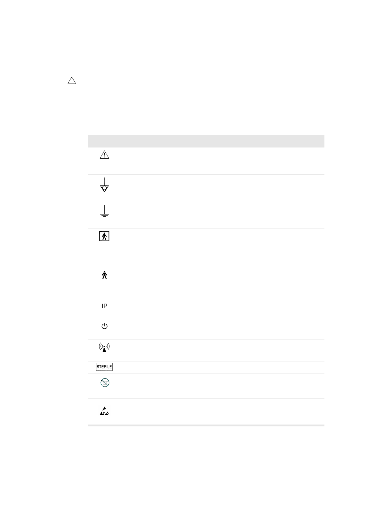
T able 1-2 contains brief e xplanations of the safety symbols used to label the scanner .
(Some labels in the table may appear on the transducer rather than the scanner itself.)
NOTE
especially the following:
!
When you encounter this sign on the scanner, consult the user guide for important
safety information.
B-K Medical disclaims all responsibility for the operating safety, reliability and
performance of the equipment if these symbols and warnings are disregarded in any
way.
Symbol Name Description
Caution or Warning Consult accompanying user guide (BB1279) when
you encounter this sign on the instrument, to a void
reducing its safety.
Potential
Equalization
Ground (earth) Additional protective ground (earth).
Type BF BF: Isolated from ground.
Type B B: Maximum patient leakage current under
Sealing Dust- and immersion-protected according to EN
Standby Standby switch on front of scanner – used to turn
Non-ionizing radiation Ultrasound scanner emits acoustic radiation.
Ter m in al conn ected to the chassis. Should be
connected to corresponding terminals on other
equipment to eliminate potential differences.
Maximum patient leakage current under
• Normal condition ≤100µA
• Single-fault condition ≤500µA
• Normal condition ≤100µA
• Single-fault condition ≤500µA
60529 [1].
scanner on and off.
20
Chapter 1
STERILE Device is in a sterile condition.
Not watertight
ESD (electrostatic
discharge)
Ta ble 1-2. Warning symbols on the scanner.
Plug may not be immersed (unless it is covered
with a special watertight plug cover).
Do not touch pins in connectors with this symbol
unless you follow ESD precautionary procedures.
Page 21

CE Marks on Electrical Devices
The European Union has introduced directives requiring b marks on devices.
Non-medical devices marked with b comply with relevant directives, for example
EEC Council Directive 89/336/EEC of 3 May 1989 concerning Electromagnetic
Compatibility.
B-K Medical devices marked with b or
93/42/EEC of 14 June 1993 concerning Medical Devices. b applies to Class I
medical devices.
c
applies to Classes Im, IIa, IIb and III. B-K Medical defines
classes assuming scanning duration for individual patients does not exceed 60
minutes.
General Safety Precautions
The ultrasound scanner is designed and tested in accordance with EN/IEC 60601-1
[2] and EN 60601–2–37 [3]. It complies with requirements for Class 1 (protective
earth) devices of EN/IEC 60601-1 [2]. It also complies with UL 2601-1 [4] and CSA
C22.2 No. 601.1–M90 [5]. It fulfills the requirements for dust protection (IP20) for
ordinary equipment specified in EN 60529 [1].
WARNING Federal law in North America restricts this device to sale to, or on the order
of, a physician.
Equipment
failure
WARNING If at any time the scanner malfunctions , or the image is severely distorted
or degraded, or y ou suspect in any way that the scanner is not functioning correctly:
• Remove all transducers from contact with the patient.
• Turn off the scanner. Unplug the scanner from the wall and mak e sure it ca nnot be
used until it has been checked.
• Do not remove the scanner cover.
• Contact your B-K Medical representative or hospital technician.
c
comply with EEC Council Directive
Isolating the
scanner
Condensation
WARNING The power supply cord connects the scan ner to the line volt age. To isolate
the scanner, you must unplug the po wer supply cord from the wa ll outlet. Do this befor e
you try to make any repairs to the system.
Caution: Large variations in temperature or humidity may cause water to condense
inside the scanner . If this happ ens , the scanner m ay fail to oper ate p roperly. Always let
the scanner come to room temperature before you plug it in.
• Wait at least 2 hours after the scanner has been subjected to major changes in
temperature or humidity.
• If there is visible evidence of condensation, wait at least 8 hours.
Before you use the scanner, make sure that all the safety requirements described in
this chapter have been satisfied.
General and Safety I nformation
21
Page 22

Explosion Hazards
Explosion
hazards
Electrical Safety
Do not use a
power strip
WARNING The ultrasound scanner is not designed to be used in potentially explosiv e
environments. It shou ld not be operated in the presence of fla mmable liquids or gases,
or in oxygen-enriched atmospheres.
There is a possible e xplosion hazard if the scanner is used in the presence of
flammable anesthetic. The scan ner should be placed at least 25cm (10 inches) from
the patient.
The ultrasound scanner contains a lithium battery. Never remove or replace this
battery. The lithium battery must not be removed except by a B-K Medical service
representative.
WARNING Do not plug the scanner into an ordinary power strip. If the ground
connection fails, this is dangerous because
• the total leakage current for all the conn ected equipment can exceed the limits
specified in EN/IEC60601-1 [2].
• the impedance of the ground connection will probably also exceed the limits
specified in EN/IEC 60601-1.
Leakage
current
Electrical
shock
ESD
WARNING When the equipment is used with 230V (and you believe the leakage
current would be within the UL limit if you were using 120V), power to the equipment
must come from an installation or supply unit with a center-tapp ed, 240V single-phase
circuit. This will make sure that chassis leakage current during single fault condition
fulfills the requirements specified in UL2601-1 [4] (limit of 300µA). If power is not
supplied in the way specified, the leakage current can be as high as 500µA, the limit
specified in EN/IEC60601-1. [2]
WARNING Never remove the cover to get access to the inside of the scanner. You
risk electrical shock if you do so. Do not allow anyone but qualified service personnel
to service the scanner.
WARNING Do not touch pins in connectors that have this symbol. Do not connect
anything to them unless you follow these ESD (electrostatic discharge) precautionary
procedures:
• Discharge your body to ground before you touch the pins with your hand or a tool.
For example, touch an unpainted metal part of the scanner cover.
• You can use a wrist strap connected to the additional protectiv e ground or potential
equalization terminal on the scanner if that is more convenient.
Anyone using the equipment should be taught to recognize the ESD symbol and to
take the necessary precautionary procedures.
22
Chapter 1
Page 23

Interference
Electrical Noise
Electrical
noise
Other
equipment
nearby
WARNING Electrical noise from nearby devices such as electrosurgical devices – or
from devices that can tran smit electrical noise to the AC line – ma y cause disturbances
in ultrasound images. This could increase the risk during diagnostic or interventional
procedures.
Electromagnetic Interference
Medical electrical equipment requires special precautions regarding EMC
(electromagnetic compatibility). You must follow the instructions in this chapter
when you install the scanner and put it into service.
If the image is distorted, it may be necessary to position the scanner further from
sources of electromagnetic interference or to install magnetic shielding.
WARNING Do not use this equipment adjacent to oth er equipment . If you must place
it next to or stacked with other equipment, verify that it operates normally there and
neither causes nor is affected by electromagnetic interference.
EMC noise can reduce the usable image depth. Therefore, in order to avoid having
to repeat an ultrasound examination, you must make sure beforehand that the
ultrasound system can be used for the examination. Repeating an examination can be
regarded as a potential risk that should be avoided, especially if the examination
involves transducers used intracorporeally or transducers used for puncture.
RF (Radio Frequency) Interference
Portable and mobile RF (radio frequency) communication equipment can affect the
scanner, but the scanner will remain safe and meet essential performance
requirements.
An ultrasound scanner intentionally receives RF electromagnetic energy for the
purpose of its operation. The transducers are very sensitive to frequencies withi n
their signal frequency range (0.5MHz to 35MHz). Therefore RF equipment
operating in this frequency range can affect the ultrasound image. However, if
disturbances occur, they will appear as white lines in the ultrasound picture and
cannot be confused with physiological signals.
WARNING Other equipment may interfere with the scanner, even if that other
equipment complies with CISPR (International Special Committee on Radio
Interference) emission requirements.
WARNING If you use accessories, transducers or cables with the scanner, other than
those specified, increased emission or decreased immunity of the system may result.
General and Safety I nformation
23
Page 24

Installation
Installation
safety
requirements
Secure the
power cord
Transducers
Electrical
shock
WARNING To ensure safe performance, a qualified electrical engineer or hospital
safety personnel mu st v erify that the ultra sound scann er is correctly in stalled and that
it complies with the safety requirements described below:
• Use only the original power supply cord. This must be fitted with a hospitalapproved three-prong grounded power plug. See “P ower Supply Cord” on
page 331.
• The equipment must only be connected to a grounded AC power supply (or wall
outlet) that meets EN/IEC/NEC requirements or applicab le local regulatio ns. The
examination room’s grounding system should be checked regularly by a qualif ied
electronics engineer or hospital safety personnel.
• Never use ex tension cables. The increased length of the cable will increase the
resistance of the protective ground conductor beyond an acceptable level.
• Keep power supply cords, sockets and plugs clean and dry at all times.
WARNING Make sure that the power cord cannot be accidentally disconnected from
the wall or the scanner.
WARNING The transducer sockets contain terminals with 5V. To avoid coming in
contact with these voltages, alwa ys connect tr ansducers to co ve r empty soc kets while
you use the scanner.
transducers
Electrical
24
Chapter 1
Type B
burns
WARNING When using Type B (non-isolated) transducers, carefully check all
electrical equipment within the patient area. Also, consider using additional protective
grounding.
WARNING Do not leave transducers in contact with the patient when using HF
electrosurgical equipment.
B-K Medical transducers fulfill EMC requirements when they are outside as well as
inside the patient’s body.
Care
Please refer to the
General Transducer Information
information about caring for transducers.
Other Safety Considerations
Mechanical failure or unintended use of ultrasound equipment can result in physical
injury to patients or operators.
(BB0555) manual for
Page 25

Mechanical
injury
Service and Repair
WARNING Be careful to avoid the following potential sources of injury:
• Parts of the body can be pinched by moveable parts of the scanner, such as the
keyboard panel and the monitor.
• Tilting the scanner can cause it to be unstable and injure someone.
• Do not lean or sit on the keyboard. The keyboard panel or monitor can break if
subjected to heavy weights or impact.
Authorized
personnel
WARNING Service and repair of B-K Medical electromedical equipment must be
carried out only by the manufacturer or its authorized representatives. B-K Medical
reserves the right to disclaim all responsibility for the operating safety, reliability and
performance of equipment serviced or repaired by other parties. After repairs have
been carried out, a qualified electrical engineer or hospital technician should verify the
safety of all equipment.
Connecting Other Equipment
!
WARNING Consult this user guide before connecting other equipm en t to terminals
marked with .
!
To fulfill EMC requirements, do not attach cables to the scanner unless they are the
same type as listed in T able B-2 on page 324 and do not exceed the maximum length
given in the table. Do not attach transducers and other accessories unless the user
guide for the transducer or accessory states that it can be used with this scanner.
Attaching other equipment may cause an increase in electromagnetic emissions or
may cause the scanner to be more sensitive to electromagnetic interference.
The scanner must not be galvanically connected to a computer network (DICOM)
that has not been isolated. If the network is not isolated, the scanner must be
connected via a network isolator DP0925 (see “Accessories”, starting on page 341).
Medical
equipment
WARNING Equipment that complies with the requireme nts of EN/IEC 60601–1 [2], UL
2601-1 [4] or CSA C22.2 No. 601.1–M90 [5] can be connect ed to the scanner, but the
power for the equipment m ust come from the auxiliary power output on the scanner or
from an independent wall power outlet. You can use the isolated auxiliary power outlets
on the scanner to connect equipment such as a monito r or video printer requiring a
total of 350VA or less. Otherwise, you can plug the scanner and othe r eq uipm ent int o
an external common isolation transf ormer in order to control the leakage current during
a ground connection fault. Follow the guidelines in EN60601–1–1 [6]. If in doubt,
contact your local B-K Medical representative.
General and Safety I nformation
25
Page 26

Non-medical
equipment:
location,
standards and
power supply
WARNING If you connect non-medical equipment (instruments that do not comply
with safety requirements for medical equipment), this equipment must be placed
outside the patient environment (1.5m from the bed, for example). The equipment
must fulfill the relevant EN standard or other applicable national or international
standard.
The power for the equipment must come from the auxiliary power output on the
scanner. You can use the isolated auxiliary power outlets on the scanner to connect
equipment such as a monitor or video printer requiring a total of 350VA or less.
Otherwise, you can plug the scanner and other equipment into an external common
isolation transformer in order to control the leakage current during a ground connection
fault. Follow the guidelines in EN60601–1–1 [6]. If in doubt, contact your local B-K
Medical representative.
Computer Security
When the Pro Focus is connected to a hospital network, B-K Medical does not take
any responsibility for computer viruses from the network that may infect the Pro
Focus.
Acoustic Output
General
Medical research has yet to prove whether or not ultrasound causes biological
effects. Therefore, prudent use considerations require you to follow certain
guidelines [3].
26
Chapter 1
Page 27

Prudent Use
Exposure
level
Training
requirements
WARNING Always keep the exposure level (the acoustic output level and the
exposure time) as low as possible.
•
Scan patients only when clinical reasons make it necessary.
•
Keep exposure time as short as possible.
•
Be careful to prepare the patient correctly so that you get the best possible
image.
•
Start scanning at a low acoustic output level (see “Thermal and Mechanical
Indices” on page 28) and increase the level only as much as necessary to obtain
a satisfactory image.
•
If you switch from an application requiring high acoustic output levels (see
“Functions Affecting Acoustic Output” on page 29), to one that requires lower
levels (fetal scanning, for example), be sure to reset the levels before you scan.
(For example, start in B-mode.)
•
T ake into account all the types of tissue that may be affected. F or example, when
scanning a breast, it may be appropriate to monitor the TI in bone rather than in
soft tissue because the ribs will be subjected to ultrasound.
WARNING Before attempting to use B-K Medical equipment, y ou should be tr ained in
ultrasonography or be under the supervision of someone who is trained in
ultrasonography. You should also be thoroughly familiar with the safe operation of your
ultrasound system and should always use the transducer best suited to the
examination.
Acoustic output data for transducers used with the scanner are given on a CD
(BZ2100) that accompanies this user guide. The uncertainty level for each parameter
measured is listed in the user guide for each transducer. For definitions of the
parameters, refer to the Food and Drug Administration (FDA) Guide [7] as well as
EN 60601-2-37 [3] and AIUM/NEMA standards [8,9].
In North America, the FDA requires all ultrasound equipmen t to be cleared before it
is marketed in the United States.
The routes (or tracks) available for clearance by the FDA are well-defined. Track 3
is for diagnostic ultrasound systems that follow the Output Display Standard. Under
Track 3, acoustic output will not be evaluated on an application-specif ic basis, but
the maximum derated Spatial Peak–Temporal Average Intensity (I
≤
720mW/cm2, the maximum Mechanical Index (MI) must be ≤1.9, and the
) must be
SPTA
maximum Thermal Index (TI) must be ≤6. All B-K Medical transducers for use with
the Pro Focus 2202 Ultrasound Scanner are T rack 3.
General and Safety I nformation
27
Page 28

Monitor Display
g
The Mechanical Index (MI) and Thermal Index (TI) can be viewed in all scanning
modes.
Thermal and Mechanical Indices
The MI and TI indices are intended to allo w users to implement the ALARA [10, 11]
(As Low As Reasonably Achievable) principle using an indicator related to a
potential bioeffect.
The full details of the indices are given in references [3] an d [9], but the formulas are
given below.
MI Formula
P
()
MI
where the variables are defined in the table below.
Variable Definition
r0.3zsp
----------------------- -=
f
c
Blood
perfusion and
TI
P
r0.3(zsp
f
c
) Peak Rarefactional Pressure (MPa), derated by 0.3dB/cm·MHz,
measured at z
) is maximum
(PII
0.3
measured center frequency (in MHz)
, the point on the beam axis where pulse intensity integral
sp
TI Formula
W
-------------=
W
0
de
TI
where the variables are defined in the table below.
Variable Definition
W
W
0
deg
time-averaged acoustic power of the source or other power parameter (W)
estimated power necessary to raise the temper ature of the target tissue one
degree Celsius (W/°C)
As a rule of thumb, the Thermal Index (TI) indicates the highest expected
temperature increase in degrees Celsius. It is based on an average level of blood
perfusion. The displayed TI may underestimate the temperature rise in poorly
perfused tissues; you must take this into account when deciding on the maximum TI
you will allow. Conversely, in areas with a rich perfusion of blood the temperature
increase will be less than the displayed TI indicates.
28
Chapter 1
Page 29

Fever
A temperature increase of one degree Celsius increase in a patient with fever may
cause complications in certain circumstances; it may be safer to delay the
investigation.
Acoustic Output Measurement
All values are measured in water according to the EN and AIUM/NEMA display
standards [3, 8, 9]. For the some of the acoustic parameters, an estimated in situ
derated value is given. This is derived assuming a tissue attenuation of
0.3dB/cm·MHz when the estimated in situ derated value (I) is described by the
following equation:
I formula
Fetal
scanning
IIwexp 0.069fz–()=
where the variables are defined in the table below.
Variable Definition
I
W
f transducer frequency (in MHz)
z distance (in cm) from the transducer face to the position where I is maximum
Intensity in water at the position where I is maximum
It should be stressed that the in situ values given are only applicable when there is
attenuating tissue between the transducer face and the focal point.
Possibility of Adverse Effects
Although it is believed that diagnostic ultrasound causes no significant biological
effects in mammalian tissue [3, 9], the user should be aware of the hypothetical
possibilities of adverse effects [10, 12, 13].
Current scientific and clinical concern over possible adverse effects is particularly
focused on fetal ultrasound scanning. It is due to the increased sensitivity of
mammalian cells and organs at this phase of their de velopment and the f act that such
a risk could have profound implications on public health. If you use high acoustic
output levels for some reason (see “Functions Affecting Acoustic Output”, below),
be sure to return to B-mode alone and turn down the power level before you do any
fetal scanning.
Functions Affecting Acoustic Output
The scanner has a control function that ensures that neither the I
value exceeds the maximum allowable value. When necessary, the scanner will
reduce the output voltage and/or PRF (pulse repetition frequency) to the transducer
in order to comply with requirements.
General and Safety I nformation
nor MI nor TI
SPTA
29
Page 30

Some of the scanner functions can affect the acoustic output, as listed here.
(Instructions for using these functions are given in the relevant sections of this user
guide.)
•
Sizing functions such as ROI (region of interest) – in general, smaller size
results in higher acoustic intensity because the pulse repetition frequency (PRF)
is higher or the ultrasound beam is more strongly focused.
•
Focus – in general, strongly focusing the beam makes the acoustic intensity
higher.
•
Frame rate – higher frame rate results in higher acoustic intensity.
•
Range – increasing the Doppler range increases the acoustic intensity by
increasing the PRF.
•
CFM Resolution – higher resolution increases the acoustic output.
•
Color box size – narrowing the color box generally increases the acoustic output
within it.
The user can set a Thermal Index limit. This will provide an upper limit for acoustic
output.
Default Acoustic Output
After the scanner has been turned off, the transducers will start in the default setup
when the scanner is turned on again. The default setup may be factory-defined or
defined by the user.
Fetal
scanning
References
The factory-defined default setup values of acoustic output for each transducer are
listed in the
General Transducer Information
(BB0555) manual.
These setups have been optimized to gi ve the best compromise between low acoustic
output and enough power to obtain the image features as quickly as possible. This is
part of the ALARA principle. The factory default setup for all transducers is B-Mode
to ensure the lowest acoustic output when you start scanning.
To change the default setup to another that satisfies the ALARA principle, see
Chapter 13, “Setting Up and Customizing Your System”.
When you enter a new patient ID, the transducer setup will be reset to the default
setup. You can prevent this from happening – see “Keeping Image Settings” on
page 40.
When you use transducers intended for fetal scanning, it is important to make sure
that the default settings are appropriate and to reset to the default setting before
scanning a new patient.
[1] EN 60529:1991+A1:2000. Specification for degrees of protection provided by enclosures
(IP code).
30
Chapter 1
Page 31

[2] EN/IEC 60601-1:1990+A1:1993+A2:1995+A13:1996 Medical electrical equipment. Part
1: General requirements for safety.
[3] EN 60601-2-37:2001+A1:2005 Medical electrical equipment – Part 2-37: Particular
requirements for the safety of ultrasonic medical diagnostic and monit oring equipment.
[4] UL 2601-1:2003 Medical Electrical Equip ment – Part 1. General Requirements for safety.
[5] CSA C22.2 No. 601.1–M90:2001 Medical Electrical Equipment – Part 1. General Require-
ments for safety.
[6] EN 60601–1–1:2001 Medical electrical equipment –Part 1-1: General requirements for
safety. Collateral standard: Safety requirements for medical electrical systems.
[7] Information for Manufacturers Seeking Marketing Clearance of Diagnostic Ultrasound
Systems and Transducers. FDA Center for Devices and Radiological Health. September
1997.
[8] Acoustic Output Measurement Standard for Diagnostic Ultrasound Equipment.
AIUM/NEMA. 1998.
[9] Standard for Real-Time Display of Thermal and Mechanical Acoustic Output Indices on
Diagnostic Ultrasound Equipment. AIUM/NEMA. 1998.
[10] Medical Ultrasound Safety. AIUM. 1994.
[11] ALARA Training Program. Ultrasound III Training. B-K Medical. 1993.
[12] Bioeffects considerations for the safety of diagnostic ultrasound. Journal of Ultrasound in
Medicine, Vol. 7, No. 9 (su pplement). September 1988.
[13] The safety of diagnostic ul trasound. The British Institute of Radiology. 1987.
AIUM: American Institute of Ultrasound in Medicine
CSA: Canadian Standards Association
EN: European Standards
FDA: Food and Drug Administration (USA)
IEC: International Electrotechnical Commission
NEC: National Electrical Code
NEMA: National Electrical Manufacturers Association
UL: Underwriters Laboratories Inc., USA
General and Safety I nformation
31
Page 32

32
Chapter 1
Page 33

Chapter 2
Getting Started
General Information
Before you turn on the scanner, mak e sure that the installation has been appro ved b y
a qualified electrical engineer or hospital safety personnel. See “Installation” on
page 24.
The controls you need to operate the scanner are located on the front.
handle on
monitor
USB
connector
release
handle
hooks for
cables
standby
switch
CD drive
reading
lights
transducer
holders
release
handle
Figure2-1. The front of the scanner.
Getting Started
33
Page 34

Adjusting the Keyboard Panel and Monitor
You can easily adjust the position of the monitor and keyboard panel to make
scanning comfortable for the operator.
release handle
Figure2-2. Handles for adjusting keyboard panel and monitor.
handle on front of
monitor
Up and down
To adjust the height of the keyboard panel:
1
Grab the panel on both sides and pull up on the two release handles.
2
Move the panel up or down.
The monitor moves up and down together with the keyboard panel.
3
Release the handles when the panel is at the height you want.
Angle
To change the viewing angle of the monitor:
•
Use the handle on the front of the monitor to swivel it from side to side and t ilt
the screen up or down.
Turning the Scanner On and Off
To turn the scanner on and off, use the green standby switch on the front of the
scanner.
To turn the scanner on:
•
Press the standby switch ONCE. A startup screen with progress bar is displayed.
Wait until the startup screen disappears and the display on the screen is stable,
indicating that the scanner is ready to use. Do not try to use the scanner until it
is fully ready.
34
Chapter 2
To turn the scanner off:
•
Make sure the scanner is completely up and running. Then press the standby
switch ONCE.
Page 35

Wait after you
press standby
switch
Wait to
unplug
Caution: Whene v er y ou turn the scanner on or off , y ou m ust giv e the oper ating system
of the scanner PC enough time to save and recover open files and unsaved data.
Otherwise, a serious system failure may occur that requires technical support.
Never unplug the scanner from the wall without turning off the standby switch and
waiting for its light to go out.
If you turn off the scanner without following the recommended procedur e (for example ,
if you unplug it while it is running), the next time you turn the scanner on, it may take a
longer time to start, and the scanner may be permanently damaged.
Checking the Date
Check that the date displayed on the screen is correct before you start scanning a new
patient (or at least at the beginning of each day).
WARNING An incorrect date will make documentation of the image incorrect and may
also cause some calculated values to be incorrect.
One cause of an incorrect date is battery failure. The battery fails very rarely. If it
does fail, the scanner will usually not operate at all, so you will know to call a
technician. However, under certain unusual circumstances the scanner will operate,
but the date will be incorrectly set to a default date.
Adjusting the Brightness of the Screen
Your scanner may be used with different levels of room lighting. Whenever the
lighting changes significantly, you should recalibrate the screen brightness.
To calibrate the screen brightness:
1
Freeze the image.
2
Press
[
Alt+Shift+G
]
on the keyboard.
A series of gray bars appears on a black background.
3
Use the contrast button on the monitor to adjust the bars so that the 100% bar is
bright white and the 90% to 10% bars seem to decrease progressively in
brightness.
4
Use the brightness button on the monitor to increase the brightness until the 1%,
2% and 3% bars (above the 10% bar) become visible.
5
Use the brightness button to decrease the brightness until the background
becomes black and the 1% bar just disappears.
Adjusting the Reading Lights
After you have turned on the scanner, you can adjust the brightness of the 3 reading
lights under the CD drive. (See Fig 2-1.)
Getting Started
35
Page 36

To adjust the reading light brightness:
•
Click
Light
under
point at
Light
Setting up a New Patient
Image
and press
on the right side of the screen and drag the slider ((or
[
+/-
]
).
Patient ID
required
Opening the Patient Window
Opening the
Patient
window
Before you scan a new patient, you must open the
information about the patient, including the patient ID. The fields in the
Patient
window and enter some
Patient
window contain information about the patient and the examination.
WARNING You must enter a new patient ID be fore you scan a ne w patient. Other wise
the documentation will not contain the correct patient identification, and you will not be
able to capture images and clips . We r ecommend that you enter the complete name of
the patient.
There are two ways to open the
Patient
window.
To open the Patient window:
•
Press
[
ID
r
]
.
or
•
Click
Enter Patient....
or the name of the previous patient in the identification
area on the screen.
The
Patient
window opens.
Change the
Pro Package
36
Chapter 2
first
Figure2-3. The Patient window.
Some fields in the
Patient
window are dif ferent, depending on which Pro P ackage is
selected. Therefore, if you want to change the Pro Package, make sure you do it
before you enter information about the patient. See the next section for how to do
this.
Page 37

If DICOM is installed on your scanner, the
Patient
window may look like the one in
Fig 2-4.
Changing Pro Package or Diagnostic Setup in the Patient Window
Click to save
patient data
and go to Pro
Package
menu window
TABto move
between
fields
E
NTER
closes
window
When the
Patient
window opens, a default Pro Package and a default Diagnostic
Setup are displayed in the window.
To change Pro Package or Diagnostic Setup in the Patient window:
1
Point at the name of the Pro Package or Diagnostic Setup.
2
Press
[
+/-
]
to toggle through the available choices.
If you click one of the default setups (instead of toggling through the choices), the
data in the
Patient
window are saved and the
Pro Package
menu window appears.
You can select a different Pro Package and Diagnostic Setup from the menu. See
“Selecting a Pro Package or Diagnostic Setup” on page 42. After you select
something from the menu, the
Pro Package
menu window closes. If you have
selected a new Diagnostic Setup, scanning begins. If you have selected a new Pro
Package, the image is frozen when the Patient window closes.
Using the Patient Window
After you have entered information in a field, press
[
Tab]
to move from field to
field. (You can also move the cursor to a field by clicking the field.)
Do not press
[
Enter] (Return
) unless you want to close the window .
[
Enter]
on the
keyboard is the same as OK in the window.)
Re-opening
Patient
window
New Patient Information from a DICOM Worklist
If you decide to enter more patient data after you have started the examination (or if
you have closed the
data), you can re-open the window. T o re-open the
name at the top of the screen. When the (blank)
Patient
window by mistake before you have finished entering
Patient
Patient
window, click the patient
window opens, click
Edit
to
restore the previously entered patient data to the fields
NOTE
: Any information you enter after you re-open the
Patient
window will not
be transferred to the patient archiving system.
DICOM® is not installed as a default on the scanner. See “DICOM Setup” on
page 199 for information about installation and setup, which must be performed by
qualified service personnel. If DICOM is inst alled, the sys tem may be set up so that
you can retrieve a worklist of patients and then select a patient from the worklist.
Getting Started
37
Page 38

To copy
information
from here
to here,
see page 39.
Figure2-4. The Patient window with worklist
Depending on how your DICOM system is set up, the worklist may appear as soon
as you open the
Patient
window. If the worklist is blank, you can retrieve the
information.
description
with image
38
Chapter 2
Sorting
Saving
To retrieve a worklist:
1
Use the drop-down windo w in the upper right corner to select the dates you want
the list to include.
2
Click
Update
.
The worklist appears in the windo w . If there are more patients than can fit in the
window, you can scroll down to see the rest of the list.
To sort the worklist by name, or any other column in the worklist, click the column
heading.
To select a patient from the worklist:
1
Click the row that contains the patient.
2
Click
Select Patient
.
The window closes. The ultrasound image on the screen is not frozen.
If you want the description from the worklist to be sav ed with patient data when you
save a scanned image, you must type the description into the
Patient
window
after
you have clicked
Select Patient
Description
field in the
(and closed the window). (See
Fig 2-4.)
Page 39

To save a description from the worklist:
1
Open the
2
Click
3
Type the description from the worklist into the
Patient
Edit
. See “Re-opening Patient window” on page 37.
window again.
Description
field.
Worklist not
updated
Entering Dates
Changes in patient data fields (except PSA) are transferred back to the DICOM
system when you save (store) a scanned image, but the w orklist is not updated.
NOTE
: Any information you enter after you re-open the
Patient
window will not be
transferred to the DICOM system.
The
Patient
window contains one or more date fields. Dates in these fields can be
displayed in various formats.
Format Example
dd-MM-yyyy
dd MMM yyyy
MM/dd/yyyy
MMM/dd/yyyy
Ta ble 2-1. Possible date formats.
The date format is set up in the
General Setup
18-11-1944
18 Nov 1944
11/18/1944
Nov/18/1944
window, but you probably will not
need to change it. See “Date/Time” on page 172.
Use number
keys
Use the number keys on the keyboard to enter dates.
NOTE:
You cannot type letters in a date field, even when the month is displayed
in letters. In the example in Table 2-1, you must type 11 for the month, even it if
is displayed as “Nov”.
To enter dates in date fields:
1
Put the cursor at the beginning of the date field.
2
Type the date (or number of the month, if your system is set to display month
first).
3
T ype a separator or press → to move to the next part of the date. You can use any
of the following separators: period (.), comma (,), hyphen (-) and slash (/). (The
separator you use when you enter a date does not affect the way the date is
displayed in the field.)
4
Type the appropriate number.
5
Repeat steps 3 and 4.
Getting Started
39
Page 40

Keeping Image Settings
When you enter a new patient ID, the transducer setup is reset to the default for the
transducer. If for some reason you want to keep the current settings when you start
scanning the new patient, you can prevent the settings from being changed back to
the default ones. Howe ver, this does not work if you change transducer or Pro
Package.
To keep transducer settings:
•
Check
The scanner uses the image settings from the previous patient.
Keep image settings
in the
Patient
window.
Keeping Patient-Related Data
When you enter a new patient ID, the patient-related data are reset to the default
values unless you want to keep the setup from the pre vious patient.
Patient-related data include the following:
•
Diagnostic Setup
•
Bodymark
•
Measurements
•
Labels
To keep patient-related data:
•
Check
The scanner uses the patient-related data from the previous patient.
NOTE:
data
Patient
you close the window, and measurements you have made are lost.
Keep patient-related data
You must check both
if you want to return to the pr evious fr ozen image when you close the
window . If you do not check both boxes, the system starts scanning when
Keep image settings
Connecting and Selecting Transducers
Connecting a Transducer
On the front of the scanner body are 3 sockets for connecting array transducers.
There can be a socket for connecting mechanical transducers.
Keep cables
tidy
Under the keyboard panel are a number of hooks that can help k eep transducer cables
tidy and out of the way. (See Fig 2-1.)
in the
Patient
window.
and
Keep patient-related
40
Chapter 2
Page 41

socket for
mechanical
transducer
(optional)
mover socket
(optional)
ECG
(optional)
Figure2-5. The transducer sockets.
To connect a transducer
1
Insert the transducer plug into the socket.
2
Turn the locking lever on the transducer plug clockwise.
To disconnect a transducer:
1
Turn the locking lever on the plug counterclockwise.
2
Remove the plug from the socket.
sockets for
array
transducers
Selecting a Transducer
Type number
displayed
must match
number on
transducer
Transducer Holders
The 4 transducer holders beside the keyboard panel keep the transducers you need
safe and ready for use. Transducer-holder inserts (DZ9756) are available to hold the
smaller transducers in the B-K Medical range. See Appendix C, “Specifications” for
a list of accessories that can be ordered to use with the scanner.
Gel Holders
The two gel holders behind the transducer holders hold gel containers ready for use.
You can choose to scan with any of the transducers that are connected to the scanner.
The type number of the transducer currently selected is displayed, together with the
scanning frequency, in the Identification area at the top of the screen. See page 67.
WARNING Before y ou start to scan, make sure that the t ype number of the tr ansducer
you hav e selected matches the n umber displayed on the screen. If they do not match,
the puncture line on the screen may not correspond to the true puncture path in the
tissue. In case of any inconsist ency, stop scanning, turn off the scanner, and contact
your local B-K Medical representative.
Getting Started
41
Page 42

To select a different transducer that can be used with the same Pro Package:
•
Point at the transducer type number on the screen and press
transducer you want.
or
•
Press the button on the transducer itself (if it has a button).
T o change Pro P ackage as well as transducer, or to see all connected transducers and
the Pro Packages that support them, see “Selecting a Pro Package or Diagnostic
Setup” on page 42.
[
+/-
]
Selecting the Scanning Plane
If you are using a biplane transducer, you can select the scanning plane (sagittal or
T
transverse). The current scanning plane (
screen after the transducer type number.
To select the scanning plane:
•
Press the appropriate button on the transducer . F or details, see the user guide for
the transducer.
or
or S) is displayed on the at the top of the
to select the
•
Click T or S (whichever is displayed) on the screen and select the value you
want, or point at T or S and press
The scanning plane in the selected view is updated to the one you select.
Pro Packages and Diagnostic Setups
Each Pro Package contains all the measurement and calculation tools you need for a
particular application area. It also contains appropriate Diagnostic Setups for the
various transducers that can be used with the Pro Package. Each transducer may ha ve
more than one Diagnostic Setup, but one setup will be the default one.
A Diagnostic Setup contains information about the scanning modes that are being
used and all the imaging information for those modes.
Selecting a Pro Package or Diagnostic Setup
The system starts scanning with the default Diagnostic Setup for the transducer and
Pro Package you are using.
The Pro Package and Diagnostic Setup currently selected are displayed in the
Identification area of the screen. See page 67.
[
+/-
]
.
42
Chapter 2
To select a Pro Package or Diagnostic Setup:
1
Press
[c]
or click the Pro Package or Diagnostic Setup displayed in the
identification area of the screen.
Page 43

The
Pro Package Menu
window appears. It contains a column for each
connected transducer . The column lists the Pro Packages and Diagnostic Setups
that you can use with that transducer.
Figure2-6. The Pro Package Menu window.
2
Select the Pro Package and Diagnostic Setup you want.
3
Click
Close
.
Saving a Diagnostic Setup
When you have changed the setup, you can save it as a new Diagnostic Setup.
To save a Diagnostic Setup:
•
Click
Save
under
Image
on the right side of the screen.
Selecting or Changing the Scanning Mode
The scanner is set up to start scanning in B-mode, unless something else is specified
in the Pro Package you are using.
To add modes to B-mode, press the key for the mode you want to add.
Performing a Biopsy or Puncture Procedure (including Brachytherapy)
When you use a puncture guide to perform a biopsy or puncture procedure, a
puncture line is superimposed on the image. When you use a transducer for
brachytherapy , a brachytherapy needle guide matrix (brachy matrix) is superimposed
on the image.
Check
puncture
guide type
number
WARNING Always check the type number of the puncture guide displayed on the
screen to make sure that it corresponds to the puncture guide that you are actually
using. If the number is incorrect, the puncture line on the screen may not correspond
to the true puncture path in the tissue.
Getting Started
43
Page 44

Check brachy
coordinates in
window with
matrix
WARNING For brach ytherap y, make sure that the brach y matrix type and coord inates
indicated on the screen (Brach y 5 mm in Fig 2-7) agree with the actual matrix template
you are using.
Verify matrix
alignment
Activate
puncture
guide or
brachy matrix
WARNING Before yo u use the brachy matrix for seed implantation, check the matrix
offset value to verify that it corresponds with the chosen matrix. Then check the matrix
alignment. See “Alignment of the Brachy Matrix” on page 206.
To superimpose a puncture line or brachy matrix on an ultrasound image:
•
Press
[w]
.
The puncture guide or brachy matrix that you previously selected appears on the
scan area unless you have selected a ne w transducer or Pro Package. In these
cases, the default puncture guide or brachy matrix appears.
44
Chapter 2
Click here to select a different
brachy matrix or puncture guide
Figure2-7. A brachy matrix on the scan area.
To select a different puncture guide or brachy matrix:
1
Click the Type number or brachy matrix name displayed at the bottom of the
scan area.
The
Puncture Guide
menu appears. It contains the puncture guides and brachy
matrices that are available for the selected transducer.
Page 45

Figure2-8. The Puncture Guide menu.
2
Click the puncture guide or brachy matrix you want.
The menu disappears and the markings on the scan area are updated.
To remove the puncture line or brachy matrix from the screen:
•
Press
[w]
.
Using the PCU (Palm Control Unit)
Use only
UA2410
WARNING Make sure that the PCU is labeled UA2410. See Fig 3-16 on page 70. If
you use a different model of PCU, pressing the keys will not have the function you
expect.
For a description of the controls on the optional PCU, see Chapter 3, “The User
Interface”.
Wait 12
seconds
NOTE:
(either because the scanner has been turned on or because the PCU has been
connected after the scanner is already running), the PCU requires 12 seconds
to calibrate the mouse stick.
Do not use the PCU – in particular, do not touch the mouse stick – for 12
seconds after power is applied. If you do not wait 12 seconds, the cursor may
drift on the screen, and you will have to unplug the PCU, plug it in again and
wait 12 seconds to get control of the cursor.
Attaching the PCU
T o connect a P alm Control Unit (PCU) to the Pro Focus, it must f irst be connected to
adaptor UA1271.
To connect the PCU:
The PCU receives power from the scanner . After power is applied
1
Connect the PCU to the adaptor. Make sure that the dot on the plug is lined up
with the dot on the socket. (see Fig 2-9).
Getting Started
45
Page 46

dots on plug and
socket
Figure2-9. Palm Control Un it plug and ada ptor UA1271.
2
Connect the adaptor to the connector on the rear of the scanner. (See Fig B-2
on page 323.
Checking the PCU
Each time you use the PCU, carefully inspect the PCU connector plug and the rubber
ring on the plug before you start. If there are any changes in the color of the plug or
the rubber ring (for example, if a grayish color is apparent), the unit must be checked
by a B-K Medical service representative before you use it.
The outside surface of the watertight plug cover may change color slightly after
repeated disinfection. This does not represent any problem.
For details of cleaning and disinfecting the PCU, see “Palm Control Unit (PCU)” on
page 202.
Putting Sterile Covers on the PCU
sensitivity
46
Chapter 2
Latex
Sterile covers (one for the PCU and one for the cable) are available for use with the
PCU. The package containing the sterile covers (UA0029) contains a PCU cover, a
cable cover, clips and some tape.
WARNING Because of reports of severe allergic rea ctions to medical devices
containing latex (natural rubber), the FDA is advising health-care professionals to
identify latex-sensitiv e pat ients and be prepar ed to treat allergic reactions promptly [1].
The procedure for putting on the sterile covers is illustrated in Fig 2-10.
To put sterile covers on the PCU and cable:
1
Always wear sterile gloves while you put on the sterile covers.
2
Put the PCU in the sterile PCU cover and twist the cover around the cable so it
fits closely.
3
Use the provided tape or clips to fasten the cover to the cable.
Page 47

4
Pull the accordion-folded cable cover over the plug and attach it to the cable
using the clips or tape.
5
Check that the cover has not been damaged by this procedure. If it has, repeat
the procedure with a new cover.
References
Figure2-10. Putting on the PCU cover and cable cover.
[1] Allergic Reactions to Latex-Containing Medical Devices. FDA Department of Health and
Human Services. FDA Medical Alert. March 29, 1991.
Getting Started
47
Page 48

48
Chapter 2
Page 49

Part 2: Working with the
Image
Page 50

Page 51

Chapter 3
The User Interface
The Pro Focus scanner has 4 types of controls, in addition to buttons on the
transducers:
•
keyboard panel controls (ke ys)
•
controls on the screen
•
foot switch (optional)
•
keys on the optional Palm Control Unit (PCU)
This chapter gives an overview of the various controls and how they are used in
general. Detailed information about using individual controls is contained in
Chapter 4, “Working with the Image” and the chapters that deal with the various
scanning modes.
Keyboard Panel Controls
The Pro Focus keyboard panel contains both an alphanumeric ke yboard and a control
panel with special scanner control keys.
The User Interfac e
51
Page 52

Keyboard
Control
panel
52
Chapter 3
Figure3-1. The keyboard panel.
The Control P anel
Each control key has a backlighted label that is visible when the functionality of the
key is available. Keys turn green to indicate an active function.
There are several types of control keys, categorized according to how you use them.
Page 53

Key types
Key Type Example Action
Press (long)
Trackball
+/-
Press
Turn
Rocker
Slider
Ta ble 3-1. Con trol key types.
Trackball
[
+/-]
[
Color]
[
Gain]
[
S
CALE
TGC
controls
z]
Rolling the trackball moves a cursor on the
screen.
Pressing the key adjusts a value or moves a
cursor stepwise up or down (pressing the +
side increases the value, pressing the - side
decreases it). A long press repeats the action.
Pressing the key activates a function or turns
something on or off. Sometimes a long press
(at least one second) is required to turn it off.
Turning adjusts the gain. Turn clockwise to
increase the gain, turn counterclockwise to
decrease the gain.
Same as for the
Moving the slider adjusts a v alue contin uously.
[
+/-]
key .
In some situations, pressing a key normally and pressing it for a longer time (at least
one second) have dif ferent effects. The longer presses are indicated in this user guide
by
press (long)
. A long press usually turns off a function.
The Control P anel Guide
The control panel guide gives a brief o vervie w of the control panel and can be stored
in the keyboard base below the keyboard panel.
The control panel guide can be
stored in the keyboard base.
Figure3-2. Store the control panel guide below the keyboard .
The Trackball and Trackball Keys
The trackball, together with the 2
to operate the on-screen controls.
[A]
(Select
) keys and the
[
+/-]
key, can be used
The User Interfac e
53
Page 54

Figure3-3. The trackball and trackball keys.
Trackball with Select Keys
+/- key
trackball
Select keys
Like a mouse
The trackball and
•
Rolling the trackball moves the cursor and other objects on the screen.
•
Pressing one of the
There is no difference between the 2
[A]
(Select
[A]
) keys are used together like a PC mouse.
keys is like clicking a left mouse button.
[A]
keys – use the one that is most conv enient
for you.
Adjusting the Trackball
The trackball should move smoothly. If it is too tight or too
loose, use the trackball adjustment tool (QA0228) to adjust it.
trackball adjustment tool
Figure3-4. Using the trackball adjustment tool.
54
Chapter 3
The tool is stored in the keyboard base below the keyboard panel. To adjust the
trackball movement, place both ends of the tool into the small holes in the black ring
of the trackball housing. Turn clockwise to tighten and counterclockwise to loosen
the trackball. The ball can be removed completely for cleaning.
Page 55

Select Keys
Click
Click (long)
+/- key
When this user guide tells you to “click” something on the screen, point at it and
press
[A]
.
•
The
[A]
key can be used to select items from lists or menus on the screen.
•
If the pointer points at a graphical control (such as the color box or one corner
of it), clicking (pressing
it. Click
the trackball can move the pointer again.
•
If the pointer points at an On/Off type on-screen control (such as
pressing
Some operations require you to point at something on the screen and then press
(long)
click (long)
+/- Key
When the pointer points at a control on the screen, pressing
such as values or sizes. A single press increases or decreases values stepwise. A
continuous press causes the value to keep changing. Pressing the right side of the ke y
increases a value, pressing the left side decreases it. If the key is pressed for more
than ½ second, the action starts repeating.
[A]
again to deselect the control or selection. Usually this means that
[A]
toggles the control off and on.
[A]
. See “Press (long)” on page 53. This is indicated in this user guide as
.
[A]
) selects the control so that the trackball can move
B Color
[
+/-]
changes settings
),
When the cursor points at Pressing the +/- key
a softkey whose value
can be changed
a graphical control
(such as the color box)
an item on a list moves the cursor up or down the list
Ta ble 3-2. E ffects of pressing the+/- key.
For more details about using the on-screen controls, see “Controls on the Screen” on
page 67.
increases or decreases
the value in the field.
increases or decreases
the size of the control.
(so you can select a value)
note: this does not apply to the setup menu
The User Interfac e
55
Page 56

Basic Keys
Basic keys
The Basic keys are arranged around the
[A]
keys for easy access. These keys w ork
in different scanning modes. For detailed information about using them, see the
chapters about the various scanning modes.
Basic keys
Figure3-5. The Basic keys on the control panel.
Key Name Key Type Action
[p]
Freeze
Press Freezes and unfreezes the image. See “Freezing the
Image” on page 73.
[
v
]Print
y
]
Save
[
[
i ]Cancel
Please note that some of the documentation func tions are on ly available after a patient ID has
been entered.
Ta ble 3-3. F unction of the Basic keys on the control panel.
Press Starts one of the user-defined documentation functions.
For more information, see “User-Defined Keys” on
page 169.
Press Starts one of the user-defined documentation functions.
For more information, see “User-Defined Keys” on
page 169.
Press Cancels the present procedure or action. Works in all
scanning modes.
56
Chapter 3
Page 57

B-Mode Keys
The B-mode keys are centered above the trackball. For detailed information about
using them, see Chapter 7, “B-Mode – 2D Imaging”.
B-mode keys
Figure3-6. The B-mode keys on the control panel.
B-mode keys
Key Name Key Type Action
[
Gain ] B Gain/Cine
[
f
[
a
[
q
Ta ble 3-4. F unction of the B-mode keys on the control panel.
B-mode
]
3D
]
Harmonic
]
T urn Adjusts the overall gain. If the image is frozen, turning
activates the Cine scroll. For more information, See
“Cine” on page 80.
Press If other modes than B are active, return to B-mode
only. If only B-mode is active, return to last mode
combination.
Press Turns 3D imaging on (if the 3D Pro Package is
installed). If 3D is already active, it steps through the
different 3D states. A long press turns 3D imaging off.
Press Turns harmonic imaging on and off.
The User Interfac e
57
Page 58

B-Mode Adjustment Keys
The B-Mode Adjustment keys are grouped on the right side of the control panel. For
detailed information about using them, see Chapter 7, “B-Mode – 2D Imaging”.
B-mode Adjustment
keys
Figure3-7. The B-mode Adjustment keys on the control panel.
B-mode
Adjustment
keys
Key Name Key Type Action
[o]
[H]
[n]
[x]
[G]
[c]
Focus
Zoom
Dynamic Range
Resolution
Width
Frequency
Press Selects the
can use the trackball a nd
focus.See “Focus” on page 122.
Press Turns on the zoom box. Press again to zoom in. A
third press resets the zoom area. A long press
turns zoom off if it is on.See “Zoom” on page 123.
Rocker Adjusts the B-mode dynamic range of the
image.See “Dynamic Range (Contrast)” on
page 123.
Rocker Increases the resolution (decreases the scanning
frame rate) or vice v ersa when y ou are scanning in
B-mode or Color mode.
Rocker Adjusts the sector width. See “Width” on page 120.
Decreasing the width increases the frame rate .
Rocker Adjusts the main (B-mode) center frequency when
you are scanning in B-mode only. If you are
scanning in Color mode, adjusts the center
frequency for those modes. See “B-Mode
Frequency – MFI” on page 127.
Focus
indicator on the screen so you
[
+/-]
keys to adjust the
58
Chapter 3
[l]
Ta ble 3-5. Function of the B-mode Adjustment keys on the control panel.
Depth
Rocker Changes the maximum depth (distance from the
transducer) of tissue shown in the image . Pushing
the + side decreases the depth (increases the
magnification). See “Depth” on page 120.
Page 59

Power and Color Mode Keys
The Power and Color Mode keys are placed to the left above the trackball. For
detailed information about using them, see the chapters about the various Doppler
modes.
Power and
Color Mode
keys
Figure3-8. The Power and Color Mode keys on the control panel.
Power and
Color mode
keys
Key Name Key Type Action
[
Gain]Color/Power
Gain
[
Power]Power Mode
[
Color]Color Mode
[j]
Ta ble 3-6. F unction of the Power and Color mode keys on the control panel.
Color Box
Turn Adjusts CFM (Color) gain if Color mode is active or
Power gain if Power mode is active.
Press T urns P ower mode (po wer Doppler) on and off . The
[
+/-]
trackball and
box when Power mode is turned on.
Press Turns Color mode (color Doppler , CFM) on and off .
The trackball and
color box when Color mode is turned on.
Press Selects the color box (the same as clicking inside
the color box on the screen). If the color box is
already selected, pressing the
selection. The trackball a nd
to the color box when color box is selected.
key are assigned to the color
[
+/-]
key are assigned to the
[j]
[
+/-]
key cancels the
key are assigned
The User Interfac e
59
Page 60

Doppler and M-Mode Keys
The Doppler and M-Mode keys are placed to the left of the trackball. For detailed
information about using them, see the chapters about the various scanning modes.
Doppler and M-
mode keys
Figure3-9. The Doppler and M-mode keys on the control panel.
Doppler and
M-mode keys
Key Name Key Type Action
[
Gain]M/Doppler
Gain
[k]
[
u
[m]
[E]
Ta ble 3-7. F unction of the Doppler and M-mode keys on the control panel.
Doppler
Mode
]
M-Mode
D/M Cursor
Update
Turn Adjusts M gain if M-mode is active or Doppler gain if
Doppler mode (spectral Doppler) is active.
Press Turns Doppler mode on and off. The trackball and
[
+/-]
key are assigned to the Doppler gate when
Doppler mode is turned on.
Press
Press In B-mode, turns on the Doppler gate so that you can
Press In combination modes, with one mode frozen,
T urns M-mode on and off . The trac kball and
are assigned to the M-line when M-mode is turned on.
position it before you activate Doppler mode. Press
again to deselect the gate. A long press removes the
gate. See “Doppler Indicator” on page 155.
changes which mode is scanning and which is frozen.
A long press unfreezes any frozen modes in the
selected view. See “Update - Partial Freeze” on
page 73.
[
+/-]
key
60
Chapter 3
Page 61

Doppler Adjustment Keys
The Doppler Adjustment keys are grouped on the left side of the control panel. For
detailed information about using them, see the chapters about the various Doppler
modes and M-mode.
Doppler
Adjustment
keys
Figure3-10. The Doppler Adjustment keys on the control panel.
The User Interfac e
61
Page 62

Doppler
Adjustment
keys
Key Name Key Type Action
[z]
Scale
Rocker Changes the scale/range/PRF in PW Doppler,
Color mode and/or Power mode. If PW is active
and Color mode or Power mode is active, the
[
Scale]
use the on-screen controls to change the scale f or
Color mode/Power mode.
key adjusts the PW mode. In this case,
[e]
[F]
[B]
[D]
[b]
[
b
On]Angle On
[
Inverse]Inverse
Ta ble 3-8. Function of the Doppler Adjustment keys on the control panel.
Baseline
Wall Filter
Sound
Steer
Angle
Rocker Mo v es the baseline of Doppler mode and/or Color
mode. If both modes are active, moves only the
Doppler mode spectrum baseline.
Rocker Adjusts the wall filter. If both Doppler and Color
modes are active, moves only the Doppler mode
spectrum baseline
Rocker Adjusts the Doppler audio (speaker) volume and
the video (speaker) volume during playback.
Rocker Changes the beam angle in Color mode, Power
mode and PW Doppler. See “Steering” on
page 155.
Rocker Changes the Doppler correction angle. See “Angle
Correction” on page 156.
Press Turns the correction angle on or off.
Press Inverts the spectrum (Doppler mode) or color scale
(Color mode). If both Doppler mode and Color
mode are active, inverts the spectrum only.
62
Chapter 3
Page 63

User-Defined Keys
The user-defined keys are placed on the right side of the trackball. By default, the
[P1]
key is set up to open the
the
Measurements
Figure3-11. The user-defined keys on the control panel.
menu.
Calculations
menu, and the
[P2]
key is set up to open
User-defined
keys
User-defined
keys
Key Name Key Type Action
[
h
P1]Calculation
[
t
P2]Measure
Userdefined
[P3]
[P4]
[
P5
]
P6
]
[
Ta ble 3-9. F unction of the user-defined keys on the control panel.
Press Opens the
“Measurements and Calculations” on page 87
and “User-Defined Keys” on page 169.
Press Opens the
the menu is already open, starts the
measurement at the top of the first o pen
measurement group. See “Measurements and
Calculations” on page 87 and “User-Defined
Keys” on page 169.
Press The function of each of the 4 user-defined k eys is
defined within each Pro Package. Their function
depends on which Pro Pac kage is being used. For
information about assigning functions to these
keys, see “User-Defined Keys” on page 169.
Calculations
Measurement
menu on the screen. See
menu on the screen. If
The User Interfac e
63
Page 64

Image Annotation Keys
The Image Annotation keys are grouped on the top right side of the control panel. For
detailed information about using them, see Chapter 2, “Getting Started” and
Chapter 4, “Working with the Image”.
Image Annotation
keys
Figure3-12. The Image Annotation keys on the control panel.
Image
Annotation
keys
Key Name Key Type Action
[w]
[
C
[g]
[
s
Ta ble 3-10.Function of the Image Annotation keys on the control panel.
Puncture
Split
]
Screen
Bodymark
Label
]
Press Turns a puncture or biopsy line on or off. See
“Performing a Biopsy or Puncture Procedure
(including Brachytherapy)” on page 43.
Press Splits the screen so two view are displayed. If the
screen is already split, pressing
which view is active. A long press turns split screen off
if it is on. See “Split Screen” on page 74.
Press Opens the
bodymark on the image. Press to close the
window again. See “Using Bodymarks” on page 78.A
long press removes bodymarks .
Press Opens the
arrows to the image. See “Placing Labels” on
page 75.A long press removes all labels and arrows.
Bodymark
Label
window so you can place a
window so you can add text or
C
shifts between
Bodymark
64
Chapter 3
Page 65

Miscellaneous Keys
The keys on the top left side of the control panel have varied functions.
Miscella-
neous keys
Miscellaneous
Figure3-13. The Miscellaneous keys on the control panel.
Key Name Key Type Action
[r]
[c]
keys
ID
Transducer/
Pro Package
Press Opens the
about a new patient. For more information see
“Setting up a New Patient” on page 36.
Press Opens the
you can choose a transducer , a Pro P ac kage or
Diagnostic Setup. For more information See
“Selecting a Pro Package or Diagnostic Setup”
on page 42.
Patient
Pro Package
window for entering data
menu on the screen so
k
]
Auto
CW Doppler
[d]
[
CW
Ta ble 3-11.Function of the Miscellaneous Control keys.
Press Turns the Auto Adjust function on and off.
Press Turns CW Doppler on and off . The trac kball and
[
+/-]
key are assigned to the CW Dopp ler gate
when CW Doppler mode is turned on.
TGC Sliders
The 8 TGC sliders to the upper right of the keyboard are used to adjust the T ime Gain
Control at various depths in the image.
The User Interfac e
65
Page 66

TGC sliders
Figure3-14. The TGC sliders on the keyboard panel.
Each slider controls 1/8th of the depth of the displayed scanned area. The top slider
affects the top of the image and the bottom slider the bottom. (W ith 360° transducers,
the top slider adjusts the part of the image that is most central – that is , closest to the
transducer. The bottom slider adjusts the part of the image farthest from the
transducer.)
Move the sliders to the right to increase gain. Mo ve the sliders to the left to decrease
gain.
Each slider is related to a part of the screen rather than a part of the tissue being
scanned. Therefore, if you move, resize or invert the scan area, you may have to use
the sliders to readjust the TGC in order to get the best image.
Keyboard
In addition to the control keys, the ke yboard panel contains an alphanumeric
keyboard for entering information into the system.
F8 and F10
The
[F1]
default functions assigned:
Key Name Default Function
[F8]
[
F10
Ta ble 3-12.Default function of the F8 and F10 keys.
to
[
F10
]
keys are user-definable keys. The
F8
F10
]
Displays a report. A report is defined for each Pro Package. The
content of the report will vary, depending on the Pro P ackage and the
measurements you have made. For more information, see “Reports”
on page 114.
Displays an arrow on the image and allows you to add text to the
image. See “Placing Labels” on page 75.
[F8]
and
[
F10
]
keys have
66
Chapter 3
Page 67

Controls on the Screen
Image area
Image area
Identification
area
Data area
Image
Documenta-
tion area
Same function as y
on the control panel
Figure3-15. The parts of the display on t he screen.
•
The Ultrasound Image area is in the center. This area displays the current
Same function as
on the control panel
p
scanning and/or frozen views. Graphical on-screen controls such as the zoom
box, color box and focus indicator are located in this area.
•
The Identification area is at the top.
This contains identifying information about the hospital and patient, the date and
time, the transducer type and scanning frequency (and scanning plane, for a
biplane transducer), and the name of the Pro Package and Diagnostic Setup.
•
The Data area is on the left side. It displays data that must be documented with
the image. Information displayed in this area is automatically updated.
The Data area has a data section at the top that contains the relev ant settings for
image parameters. It has a measurement section at the bottom. The measurement
section displays the results of current measurements you have made.
The Image area, the Identification area and the Data area make up the Image
Documentation area and will appear in documentation (except for the Pro Package
and Diagnostic Setup names).
The User Interfac e
67
Page 68

Image and
Measurement
area
Browser area
Point and Click
•
The Image and Measurement area is to the right. You may need to click
to see the image tools or click
Measurements
to see the measurement tools.
Image
This area will not appear in documentation.
•
The Browser area is at the bottom. Small pictures (thumbnails) of the clips and
images stored in the scanner are displayed across the bottom of the screen. This
area will not appear in documentation.
Using the trackball and trackball keys to interact with the controls on the screen is
intuitive and easy. In this user guide, certain terms are used consistently to tell you
what to do.
Terminology
Point at
Click (select)
Drag
Use the trackball to move the pointer to a control. When a co ntrol is
can adjust it with the
[
+/-]
key but you can not move it. To move a graphical control,
you must select it.
Point at an on-screen control and press
trackball resizes or moves it. (Pressing
[A]
. When a control is
[A]
again cancels the selection, making it
selected
possible to use the trackball to move the pointer.)
Use the trackball to move a cursor or graphical control.
When an on-screen
control has the color
White Available Point at it or select it.
Orange Pointed at
Blue Selected Move it with the trackball.
Gray Unavailable (No action possible).
Ta ble 3-13.Color coding of controls on the screen.
It is You can
Adjust it with
Select it.
Adjust it with the pointer or
[
+/-
]
.
pointed at
, moving the
[
+/-]
, you
68
Chapter 3
Moving
For some actions, you do not need to click. You can just point and press the
key (see the following section).
To move a graphical control on the screen:
1
Click the control to select it.
2
Drag the selected control to the position you want.
3
Click to release the trackball for other uses.
[
+/-]
Page 69

Changing size
To resize a graphical control on the screen:
•
Select or point at the control and press
[
+/-
]
.
or
1
Click a boundary of the control (such as a corner of a box or a boundary of the
focus indicator) to select it.
2
Drag the selected control part until the control is the size you want.
3
Click to release the trackball for other uses.
Softkeys
The screen contains many softkeys for functions whose value can be adjusted or
changed. These softkeys appear as words or abbreviations on the screen.
Softkeys with
values
Slider
softkeys
On/Off
softkeys
Small green
light
To select a value for a softkey:
1
Click the softkey.
A list of possible values appears.
2
Click the value you want.
You can also use
NOTE:
[
+/-]
to scroll up and down in the list and then press
[A]
Not all softkeys may be visible . Click the e xpand symbol to see the all
items in a menu. To change the setup for how menus appear, see Chapter 13,
“Setting Up and Customizing Your System”.
Some softkeys have a slider that you move with the trackball.
Some softkeys have only two values, On and Off.
To change the setting of an On/Off softkey:
•
Click it.
or
•
Point at it and press
[
+/-]
to toggle the value.
A small green light next to the key indicates that it is set to On.
.
Foot Switch
The optional foot switch has 2 pedals. You can assign a function to each pedal, and
the same pedal can have different functions for different Pro Packages. For
information about assigning functions to the pedals, see“User-Defined Keys” on
page 169.
The User Interfac e
69
Page 70

To use the foot switch:
•
Press the appropriate pedal.
NOTE:
Releasing the pedal does not operate or r everse the function.
Palm Control Unit (PCU)
You can use the optional PCU UA2410 to operate the scanner at a distance from the
keyboard panel. The PCU plugs into a socket on the back of the scanner . See page 45
for important information about waiting 12 seconds before using the PCU and about
checking the part number.
70
Chapter 3
Check PCU number here.
Figure3-16. The PCU.
Some of the PCU controls work like particular ke ys on the control panel. Some work
differently. Table 3-14 contains an o verview of the PCU controls and which control
panel keys they relate to.
Page 71

PCU Control Control Panel Key
+ Name
Function
Activates Picture in Picture (PiP). (PiP is an optional
feature.) Displays an external image and an
ultrasound image simultaneously. One image is
large, one is small.
Short press toggles through 3 views: small external
image, small ultrasound ima ge, external image only.
Long press turns off PiP (returns to ultrasound
image only). See “Toggling through the PiP States”
on page 85.
c
MHz
w
P1, P2
K
l
f
[
Frequency
Frequency
[w]
Puncture
[P1], [P2]
User-defined
[
K
Measure
[l]
Depth
[
Gain
B Gain/Cine
If Power mode or Color mode is active, press to
c
]
toggle through the Power mode or Color mode
frequencies for the selected transducer. If B-mode
only is active, press to toggle through the B-mode
frequencies.
A long press opens the Pro Pac k age Men u window
(see page 43), so you can select a different
transducer, Pro Package or Diagnostic Setup.
See “Puncture” on page 64.
User-defined ke ys.To assign functions to these
keys, see page 170.
]
]
User-defined keys. See “Measure” on page 63.
See “Depth” on page 58.
B Gain only. See “B Gain/Cine” on page 57.
-
and
p
A
+
[p]
Freeze
[A]
Select
[
+/-
]
+/-
Freez es and unfreezes the image. See “Freezing
the Image” on page 73. A long press starts one of
the user-defined documentation function s.
See “Select Keys” on page 55.
See “+/- Key” on page 55.
The User Interfac e
71
Page 72

PCU Control Control Panel Key
+ Name
Function
Mouse Stick Trackball
k
z
C-Gain
Color
Ta ble 3-14.Controls on the PCU.
[k]
Doppler Mode
[z]
Scale
[
Gain
]
Color/Power Gain
[
Gain
]
M/Doppler Gain
[
Power
]
Power Mode
[
Color
]
Color Mode
See “Trackball with Select Keys” on page 54. If you
push the mouse stick farther from the center
position, the cursor moves faster.
See “Doppler Mode” on page 60. A long press on
this key steps through the partial freeze states.
See “Scale” on page 62.
Doppler gain. If Doppler mode is active and not
partially frozen, press to modify Doppler gain.
If Doppler mode is not active , modifies Color gain (i f
Color mode is active), and modifies Power gain (if
Po wer mode is active).
Toggles Power or Color mode, whichever was the
last used, on and off. A long press t oggles betw een
Color and Power modes.
Transducers
Control button
Long press
Some transducers have a control button that you can press to
(freeze frame).
You can set up your system so that a long press (more than one second) starts one of
the user-defined documentation functions, such as capturing an image.
If the transducer has more than one control button, you can set up a user -defined long
press function for each control button.
Each time the control button is pressed, a ‘beep’ is emitted.
Start
or
Stop
scanning
72
Chapter 3
Page 73

Chapter 4
Working with the Image
To adjust and work with the image (for example, to resize the image or to make a
measurement), you can usually use the trackball keys to point and click and drag. In
some cases (for example, to freeze the image), you can use special keys on the
control panel. For more information about using the trackball and other keys, please
see Chapter 3, “The User Interface”.
Image Orientation
You can change the horizontal or vertical orientation of a 2D image. The view must
be scanning when you change orientation.
To change Left/Right or Up/Down orientation:
•
Click
L/R
or
U/D
under
The images of all modes in the selected view are inverted horizontally or
vertically.
Image
on the right side of the screen.
NOTE:
settings for the B-mode image. See “TGC” on page 121
When you change image orientation, you may need to adjust the TGC
Freezing the Image
To freeze the image, press
transducer itself – see the transducer user guide for information about this.)
All images on the screen are frozen.
If you press
NOTE:
are also frozen, so the time displayed on a printed image is the time the image
was frozen, not the time it was printed.
[p]
When you freeze the image , the date and time displayed on the screen
Update - Partial Freeze
Partial freeze is something you can do only when you are scanning in Doppler mode
as well as one or more 2D modes (B-mode, color and po wer). Partial freeze lets you
freeze only the Doppler image or only the 2D-mode image.
To start partial freeze:
[p]
or click
again, the image returns to its previous state.
Freeze
. (You can also use the button on the
•
Press
[E]
.
Working with the Image
73
Page 74

The partial freeze state starts with 2D-modes frozen and Doppler mode
scanning.
When partial freeze is turned on, pressing
states:
•
•
To end partial freeze:
•
Split Screen
You can split the screen horizontally or vertically to display 2 views side by side or
one over the other. If simultaneous scanning is turned on, both views can be
scanning.
To split the screen:
•
[E]
toggles the display between the 2
Doppler mode frozen; 2D-modes scanning.
2D-modes frozen; Doppler mode scanning.
Press (long)
Any frozen modes in the selected view start scanning.
Press
[
The screen is split to display 2 scan images.
If you are using a single-plane transducer , the 2 views contain the same scanning
view.
C
[E]
]
.
.
If you are using a biplane transducer, each view displays the imag e from one
scanning plane.
To select one of the views:
•
Click in the view you want to select.
or
•
Press
[
C
]
to select the view that is not currently selected.
To remove the split:
•
Press (long)
The currently selected view is resized to fill the screen.
[
C
]
.
Simultaneous Scanning
The 2 views in a split screen can both be scanning simultaneously; in this case,
freezing and unfreezing affect both images.
To turn simultaneous on and off:
•
Click
Simultan
on the right side of the screen.
74
Chapter 4
Page 75

Color or
power in one
view only
NOTE:
color or power mode. Thus if one view has B+Color or B +P ower, the other view
contains only a B-mode image.
In simultaneous split-screen scanning , only one of the views can contain
Labelling Parts of the Image
You can place text labels and arrows anywhere on the ultrasound image. You can
select a label from a catalog or type a new one. Label catalogs can be customized in
many ways. See “Label Setup” on page 191.
NOTE:
will stay pointing at the same an anatomical structure. (That is, it will move with
the image.) A label with no arrow will stay on the same part of the screen and
not move with the image.
You can add more than one label to an image.
If you move the image or c hange its scale, an arr ow or label with arrow
Placing Labels
Your system can be set up so that you can type labels directly on the image or select
a label from the label catalog. See “Label Setup” on page 191.
To label the image:
•
Type the label.
You can also use the
Using the Label Window
To open the Label window:
•
Press
[
s
Label
]
or [F9].
window.
The
Label
most recently (for the Pro Package you are using). The label that you used most
recently is displayed in the
Use the drop-down menu at the top of the window to select other catalogs.
window appears, displaying the label catalog that you have used
Edit
field.
Working with the Image
75
Page 76

Drop-down menu
Edit field
Check here to have
an arrow attached
to the label
Figure4-1. The Label window with the Surgery catalog displayed.
To use a label from the Label window:
1
To use the label in the
To use one of the other labels in the catalog, click the label text you want.
Edit
field, go to Step 2.
To edit the label in the
the field.
To attach an arrow to the label, check the box next to the arrow. (See Fig 4-1.)
2
When you have selected the label you wa nt and decided whether it should ha v e
an arrow attached, press
The
Label
menu disappears and the label itself appears on the image in the
default position.
Edit
field or use a label that is not in the catalog, type in
[
Enter]
or click OK.
Arrows
You can place arrows anywhere on the image to indicate a region of particular
interest. You label the arrow.
To place an arrow on the image:
1
Press
[
F10
]
.
An arrow appears.
2
If you want to label the arrow, type the label.
The label appears next to the tail of the arrow.
3
Drag the arrow to the required position and click
.
76
Chapter 4
To change the direction of an arrow or move it:
1
Click the arrow to select it.
Page 77

2
Press
[
+/-]
to change the orientation of the arrow.
The tail of the arrow moves in a clockwise direction with each press. If the arrow
is labelled, the label moves with the tail of the arrow.
3
Click.
Moving Labels and Arrows
To move a label or arrow that you have already positioned, click it and drag it to the
new position. Click again when the label or arrow is where you want it.
Creating and Editing Labels
You can create new labels and edit the text of existing ones.
Adding a label
Editing a label
on the image
Removing Labels and Arrows
To add a label to the catalog:
1
If the label menu is not already displayed, press
2
Type the new label text in the
3
Click
Save Label
You can also use the
“Label Setup” on page 191.
To edit a label on the image:
1
Click the label on the image to select it.
2
Press
[F9]
The Label menu appears with the text of the selected label in the
3
Edit the label text.
4
To save the edited label to the list, click
5
To change the label on the image to the new, edited name, click OK.
You can also click the label and edit it directly on the image.
.
Label Setup
.
Edit
field.
window to create or delete labels in a catalo g. See
Save Label
[F9]
.
.
Edit
field.
To remove a label or arrow from the image:
•
Click (long) the label or arrow you want to remove. (This means “Press (long)
[A]
while pointing at the label.”)
To remove all labels from the image:
•
Press (long)
or
1
Press
The
[F9]
Label
[
s
].
.
menu appears.
Working with the Image
77
Page 78

2
Click
Using Bodymarks
Bodymarks are small bitmaps depicting parts of the body. You can place a bodymark
anywhere on the ultrasound image.
You can set up a user-defined ke y to place a frequently-used bodymark. See
“Assigning User-Defined Keys” on page 170.
A scanning plane indicator can be placed on the bodymark in order to show the
scanning position.
Figure4-2. Bodymark with scanning plane indicator.
Clear All
.
Scanning plane indicator
Scanning
plane
indicator
The scanning plane indicator consists of a long bar and small square. The orientation
of the bar indicates the orientation of the probe on the body , and the square indicates
the part of the probe that corresponds to the upper left of the scanned image on the
screen.
Bodymarks are organized in catalogs. You select the one you want from one of the
catalogs. Bodymark catalogs can be customized in many ways. See “Bodymark
Setup” on page 189.
78
Chapter 4
Page 79

Adding a Bodymark
Figure4-3. The Bodymark window with the General catalog displayed.
To place a bodymark on the image:
1
Press
[g]
.
The
Bodymark
catalog for the Pro Package you are using.
Use the drop-down menu at the top of the window to select other catalogs.
2
Click the bodymark you want.
The
Bodymark
a scanning plane indicator. You can rotate or drag the scanning plane indicator
to a different position.
window appears, displaying the most-recently-used bodymark
window closes, and the bodymark appears on the screen, with
Moving a Bodymark
To move a bodymark, click it, drag it to the position you want, and click again.
Adjusting the Scanning Plane Indicator
To adjust the scanning plane indicator, click it. You can then:
•
drag it with the trackball
•
rotate it with
Click again when the scanning plane indicator is the way you want it.
[
+/-
]
Working with the Image
79
Page 80

Replacing a Bodymark
To replace an existing bodymark with a different one, click the bodymark on the
screen and select a new bodymark from the
Bodymark
window that appears.
Setting a Default Position fo r Bodymarks
For each Pro Package, you can set a default position for bodymarks. Whenever you
place a bodymark, it appears in the default position on the image. (You can move it.)
The position and angle of the scanning plane indicato r are also saved as part of the
default.
To set a default position for the bodymark:
1
On the image, move the bodymark to the position you want.
2
Adjust the position and angle of the scanning plane indicator on the bodymark.
3
Click the bodymark.
The
Bodymark
4
Click
Save Position
The bodymark position and the scanning plane indicator position and angle are
all saved as default for the Pro Package. Whene v er you place a bodymark on an
image while using the current Pro Package, it will appear in this default position.
You can move it, of course.
window appears.
.
Cine
Removing a Bodymark
To remove a bodymark from the screen:
•
Point at the bodymark and click (long).
or
•
Press (long)
Unless you delete it or replace it with a new one, a bodymark will remain on the
screen until you change Pro Packages or begin to scan a ne w patient.
[g]
.
Adding New Bodymarks
You can import your own images to the bodymark catalog. See “Importing
Bodymarks from a File to a Catalog” on page 190. The bodymarks are 100 x 100
pixel black and white bitmaps. Larger images will be scaled.
Cine (image review) lets you review a series of the most recently recorded B-mode,
B+Color mode, B+M-mode or B+Doppler mode images. You can scroll backward
or forward through the series.
80
Chapter 4
Page 81

Scanned images are constantly being saved and stored for re vie w. When the storage
capacity is reached, the oldest images are discarded as new ones are stored. The
number of images that can be stored for review varies, depending on such factors as
image resolution and size.
Image (frame)
numbers
Images viewed with the C
certain parameters that affect the image will cause already-stored images to be
discarded. If this happens, there will not be a full set of images to be reviewed until
the storage has had time to fill again.
You can change some of the settings for the
changing Cine functions see “Clip Storage and Cine Setup” on page 173.
To turn Cine on and off:
•
Press
[p]
to stop scanning.
A vertical cursor line appears and
of the screen.
The current image (
NOTE:
number 1.
To review the images:
•
or
Higher numbers are farther in the past. The image scanned most recently is
Click
Frame
under
INE
function must be comparable. Therefore, changing
Cine
function. For information about
Cine
appears below
Frame
) number is displayed in the
Cine
and drag the slider to select the frame number.
Image
Cine
on the right side
menu.
•
Select the cursor by clicking on it and press
images.
NOTE: +
previous image (higher image number).
goes to the next image (lower imag e number) and - goes to the
[
+/-
]
, or drag to scroll through the
Using Cine in M-Mode or Doppler Mode
When cine is activated while scanning in M-mode or Doppler mode, a vertical cine
cursor is displayed overlaying the Doppler or M-mode image.
The B-mode image displayed is always the one that corresponds to the position of
the Doppler or M-mode cursor. The image (frame) number in the
corresponds to the B-mode image.
To make measurements on a cine image or record it:
1
When the desired image is displayed, press
controlling the image review.
2
Make measurements on the image or record it in the usual way.
[A]
to release the trackball from
Cine
Working with the Image
indicator
81
Page 82

Cine Play
Cine Loop
You can also review the images as a movie using
Cine Play
.
To review the images using Cine Play:
•
Click
During
Cine Play
Cine Play
under
Cine
on the right side of the screen.
the image with the highest frame number (oldest) is displayed first,
followed by images with decreasing frame number (newer). After the newest image
has been displayed,
Cine Play
will begin again with the highest frame number and
repeat the sequence.
Start and Stop Markers
The
Start
and
Stop
marker positions are displayed under
You can choose the range of images to be displayed in
and Stop markers in the
Cine
menu.
Cine
Cine Play
(See Fig 4-4).
by setting the Start
To Set a Start or Stop Marker:
1
Click on
2
Drag the
3
Click the marker you want to set.
NOTE:
Frame
Frame
.
slider to select the required frame number.
The image chosen for the Start marker must be older (the F rame number
must be higher) than the image chosen for the Stop marker.
Start marker
Stop marker
Figure4-4. Cine Menu with Start and Stop markers.
Playback Speed
You can adjust the speed at which images are reviewed.
To adjust the playback speed:
•
Click
Speed
and drag the slider to the required value.
The available values range from 0 (slowest) to 100 (fastest).
The Video Window and Picture in Picture (PiP)
You can display a video image on the screen. The video image can come directly
from a camera (endoscope, for example), or it can be played back from a video
recorder.
82
Chapter 4
Page 83

Using the Video Window
Video window
Picture in Picture (PiP), which can be purchased as an option for the Pro Focus, lets
you view two types of images at the same time, on the same screen: an ultrasound
image and a video image.
T o run the PiP softwa re, you must hav e a license from B-K Medical. For information
about activating the PiP option, see “Licenses” on page 196. For more information
about purchasing the PiP option, see Appendix C, “Specifications”.
When you display a video image on the screen (and are not using PiP), the video
image appears in a window that covers the ultrasound image and the on-screen
controls to the left of the image. It also covers the patient ID and some other
information at the top of the screen. This large window is called the
video window
.
To activate the video window:
•
Click
Video
under
Image
on the right side of the screen.
or
•
If the PiP window is open but the main image is an ultrasound image, press
on the PCU to toggle the state (see Fig 4-6 on page 86).
Unfreeze
Changing
audio volume
To close the video window:
•
Click
Video
under
Image
on the right side of the screen.
or
•
Press (long) on the PCU.
The video window cov ers the ultrasou nd image. Therefore you cannot use any keys
or on-screen controls that affect the ultrasound image when the video window is
open.
NOTE:
You can use the C
You cannot move or resize the video window.
OPY
and F
REEZE
functions.
If you unfreeze the ultrasound image, the video window closes if PiP is not turned on.
To change the audio volume of the video signal, press
[
Sound
B]
.
Changing the Video Setup
The video setup determines how the video image looks. You can change the video
setup while a video image is displayed in the video or PiP window. You use the
Video Setup
window to specify the video source (the connector on the back of the
scanner and the equipment that is attached to it). The video format (PAL or NTSC)
that is set in the
General Setup
window also affects the video input. See “Video
Format” on page 172.
Working with the Image
83
Page 84

To change the video setup:
•
Click
Video Setup
under
Image
on the right side of the screen. (
must be selected.)
The Video Setup window appears.
select video source here
change video brightness, contrast and saturation here (not available with RGB)
click here to restore default settings for selected video source
click here to save current settings as default for selected video source
Figure4-5. The Video Setup window.
Table 4-1 explains the video source options.
Video Source Connector Equipment Attached (Example)
S-Video/Camera S-VHS video camera.
S-Video/VCR S-VHS VCR
Video
or
PIP
Using PiP
PiP window
S-Video/AUX A different S-VHS video camera.
Composite/Camera Composite video camera.
Composite/VCR Composite VCR
Composite/AUX A different composite video camera.
RGB RGBS video camera
Ta ble 4-1. T he video source options in the Video Setup window.
NOTE:
The equipment names (Camera, VCR, AUX) are just labels so that you
can save setups for different equipment. If you plan to use three different
composite video cameras, then you can use one of the first three options in the
table for each camera.
See page 323 for the location of the connectors on the back of the scanner.
When you use PiP (Picture in Picture), there are two image windo ws on the scree n –
one large and one small. The
PiP window
is the smaller window. If the main image
on the screen is an ultrasound image, the PiP window contains an external video
image. If the main image is a video image, the PiP window contains an ultrasound
image.
84
Chapter 4
Page 85

Do not cover
patient ID or
other
important
information
WARNING
on the screen. Make sure that all important information – including the patient ID – will appear if
you print or save the ultrasound image.
When you use Picture in Picture, do not cover critical information (such as TI or MI)
If the PiP window is outside the image documentation area (see page 67), it will not
appear when you print the image. You must make sure that the PiP window is in a
suitable position for your purposes.
To display the PiP window:
•
Click
PIP
under
Image
on the right side of the screen.
or
•
Press on the PCU.
The contents of the PiP window when it opens depends on whether the video window
is active (open) when you turn on PiP.
Video Window PiP Window Contents
Not Active Video from external video signal
Active Ultrasound image
Ta ble 4-2. Con tents of the PiP window when it opens.
To turn off PiP:
•
Click
PIP
under
Image
on the right side of the screen.
or
•
Press (long) on the PCU.
Toggling through the PiP States
If the video window is not acti ve, pressing turns on PiP, with a video image in the
smaller window.
A second press transposes the images so that the video image is in the big window
and the ultrasound image is in the smaller PiP window.
A third press turns off PiP but leaves the video image on the screen.
A fourth press goes back to the initial PiP state, with the ultrasound image big and
the video image in the PiP window.
Further presses toggle around the three states that include a video image on the
screen. A long press on returns you to normal scanning with no video image on
the screen.
Fig 4-6 illustrates the effect of successive presses.
Working with the Image
85
Page 86

Figure4-6. Effect of using the PiP key on the PCU to toggle through various PiP states.
Available
controls
When the PiP window contains an ultrasound image, most ultrasound controls are
disabled. You can only use G
Adjusting the PiP window
The PiP window can be placed anywhere on the screen. It can have 3 possible sizes.
To reposition the PiP window:
1
Click inside the window.
2
Drag the frame to the position you want.
3
Click.
The PiP window moves to the new frame position.
If you decide you do not want to mo ve the windo w, press
is not selected anymore.
To change the size of the PiP window:
•
Move the cursor so that it is inside the window and press
decrease the window size.
or
AIN
, TGC, F
REEZE
and C
OPY
functions.
[
Esc
]
or
[i]
[
+/-
]
to increase or
. The frame
86
Chapter 4
•
Click inside the PiP window and then press
window frame size. When you are finished, the PiP window changes size to fit
the frame.
[
+/-
]
to increase or decrease the
Page 87

Chapter 5
Making Measurements
Measurements and Calculations
You can use a variety of tools to measure aspects of the ultrasound image (and thus
the underlying tissue). These measurements can be used for various calculations.
Accuracy
For information about the accuracy of dif ferent types of measuremen ts, see
Transducer Information
Each Pro Package contains the measuring tools that you will need for the calculations
that the package contains. You can find descriptions of all the calculations in the Pro
Package chapters.
You can also define customized measurements that you want to use. See “UserDefined Measurements” on page 178.
To view the list of measurements:
•
Freeze the image.
The names of all available measurements are displayed under
the right of the image.
If the list is not visible, click
To see more measurements, scroll with the trackball.
(BB0555).
Measurements
Making a Measurement – General Procedure
The sections following this one contain detailed descriptions for using the various
measuring tools.
Measurements
to expand the list.
General
to
Image must
be frozen
NOTE:
To make a measurement:
1
Click the name of the measurement.
If you can use more than one measuring tool to make the measurement, a small
triangle
list. Click the measuring tool you want to use.
A marker appears on the image.
2
Drag the marker to the position you want. Click.
If the measurement requires 2 markers, another one appears.
3
Drag the second marker to the position you want. Click.
The image must be frozen.
▼
appears to the right of the measurement. Click the ▼ to expand the
Making Measurements
87
Page 88

4
Repeat this until you have positioned all the markers for the measurement.
NOTE:
depend on what you are measuring.
The look of the markers themselves and of any lines that connect them
Measurement
results
displayed
Clearing a Measurement
Clearing All Measurements
Results
bottom of the data area to the left of the image.
Depth
B-mode or Color mode image, the displayed measurement is the depth of the marker
(distance from the marker to the transducer surface along the scan line). When a
second marker is positioned, the depth is replaced by the appropriate measurement
result.
There are 3 ways to clear a measurement and any current calculations that use the
measurement.
To clear a measurement, do one of the following:
•
•
•
The results of the measurement are displayed (continuously updated) at the
While you are positioning the first marker for a distance measurement in a
Point at the marker and press (long)
Point at the measurement result and press (long)
Press
[
Esc
]
while the measurement is selected on the screen.
[A]
.
[A]
.
B-Mode and Color Mode Measuring Tools
Measuring a
distance
You can clear all the measurements on the screen at once.
To clear all measurements:
•
Press (long)
Distance Measuring Tool
Two markers can be positioned to measure a distance – the length or width of a
structure, for example. When the first mark er is positioned, a second one appears for
you to position.
NOTE:
[
K
Pressing
]
[
K
.
]
starts a distance measurement.
88
Chapter 5
Page 89

Position first marker. First marker positioned;
Figure5-1. Positioning 2 markers on a B-mode or Color mode image.
position second marker.
Second marker positioned.
Repositioning
a distance
marker
Measuring
distances at
right angles
NOTE:
The small numbers in the pictures (1,2) indicate the order in which the
markers appear. The numbers do not appear like this on the screen.
To move a marker after they have all been positioned:
1
Click the marker.
2
Drag it to the new position.
3
Click.
Perpendicular Distances
Sometimes it is important for one distance to be measured perpendicular (at right
angles) to another distance. In this case, a small square appears at the intersection
point when the two measurement lines are perpendicular to each other.
Angle Measuring Tool
On a B-mode or Color mode image, you can measure 1 angle or 2 angles. The angle
measuring tool works slightly differently from the other measuring tools. The
numbers in the instructions below refer to the numbers on the markers in Fig 5-2.
To measure an angle:
1
Click Angle.
A marker appears.
2
Position the marker and click.
A second marker appears, with a line connecting the two markers.
3
Position marker #2 to change the angle of the line. Click.
A third marker appears.
4
Position marker #3 and click.
A fourth marker appears, with a line connecting it to marker #3.
5
Position marker #4 to change the angle of the line. Click.
alpha
Angle
between the two lines is indicated on the image and the size of the
angle appears as a measurement to the left of the image.
Making Measurements
89
Page 90

If you have chosen to measure 2 angles, additional markers appear for you to
measure another angle (
beta
) with the first line.
Position first marker and click.
Line appears.
Position marker 4 and click.
Figure5-2. Using the angle measuring tool to measure two angles.
Line appears.
Position marker 2 and click.
Angle alpha is measured.
Marker 5 appears.
Position it and click.
Marker 3 appears.
Position it and click.
Line appears. Position
marker 6 and click.
Angle beta is measured.
If you just click and do not move any markers, the default angles are 60º.
To change the angle measurement after all the lines are positioned:
•
Click any marker and move it to change the length or orientation of one of the
lines.
NOTE:
If you click somewher e on the measuring tool that is not on a particular
marker, moving the trackball moves marker #1.
90
Chapter 5
Circle Measuring Tool
On a B-mode or Color mode image, you can position 2 markers to measure a circle.
Position the markers in the usual way. As you move the second marker, the circle is
continuously redrawn on the screen.
Page 91

Position first marker. First marker positioned;
Figure5-3. Using the circle measuring tool.
position second marker.
Second marker positioned.
After the markers have been positioned, you can move any of them by clicking and
dragging to a new location. Click again.
Repositioning
a circle
marker
To change the location or size of the circle:
1
Click one of the markers
2
Reposition the marker.
3
Repeat with the other marker, if necessary.
All markers positioned. First marker selected. First marker repositioned.
Figure5-4. Repositioning one of the circle markers.
To move the entire circle without changing its size:
1
Click inside or on the circle.
2
Drag it.
3
Click again.
Moving a
circle
All markers positioned. Entire circle selected. Entire circle repositioned.
Figure5-5. Moving a circle you have drawn.
Making Measurements
91
Page 92

Ellipse Measuring Tool
On a B-mode or Color mode image, you can use three markers to measure an ellipse.
Position the markers in the usual way. The first 2 markers determine a line that is
used as the axis of rotation if you use the ellipse to measure volume. The third marker
is always equidistant from the first 2. Moving it makes the ellipse broader or
narrower. As you move the third marker, the ellipse is continuously redrawn on the
screen.
Repositioning
an ellipse
marker
Position first marker. First marker
Figure5-6. Drawing an ellipse.
positioned; position
second marker.
First and second
markers positioned;
position third marker.
All markers
positioned.
After the markers have been positioned, you can move any of them by clicking and
dragging to a new location. Click again.
NOTE:
All markers positioned. First marker selected. First marker repositioned.
Moving marker 1 or 2 in an ellipse will automatically move marker 3.
92
Chapter 5
All markers positioned. Third marker selected. Third marker repositioned.
Figure5-7. Repositioning markers in an ellipse you have drawn.
To move the entire ellipse without changing its size or orientation:
1
Click inside or on the ellipse.
2
Drag it.
Page 93

Moving an
ellipse
3
Click again.
All of the ellipse does not have to lie within the ultrasound image.
Closing the
polygon
All markers positioned.
Figure5-8. Moving an ellipse.
Entire ellipse selected.
Entire ellipse repositioned.
Pol ygon Measuring Tool
On a B-mode or Color mode image, you can position a number of markers to define
the outline of a polygon. Position the markers in the usual way. After you position
one and click it, a new marker appears. A dotted line connecting it to the previously
positioned marker is continuously redrawn as you drag the ne w maker and click it to
position it.
To delete the marker you have just positioned:
•
Press
-
on the [+/- ] key .
To undo the deletion:
•
Press +.
When you have positioned the final marker you want to use,
double-click
it to
indicate that it is the final marker in the polygon. A line is drawn from it to the first
marker. No new marker appears after you double-click the final one.
Position first marker.
Figure5-9. Drawing a polygon.
First marker positioned;
position second marker.
Additional markers
positioned; shape is
automatically closed.
After the markers have been positioned, you can move any of them by clicking and
dragging to a new location. Click again.
Making Measurements
93
Page 94

Repositioning
a polygon
marker
Moving a
polygon
Marker repositioned.All markers positioned. Marker selected.
Figure5-10. Repositioning one of the markers in a polygon.
To move the entire polygon without changing its size or orientation:
1
Click inside or on the polygon.
2
Drag it.
3
Click again.
You can move the shape to any location in the view.
Erasing what
you have
drawn
Entire shape selected. Entire shape repositioned.All markers positioned.
Figure5-11. Moving a polygon you have drawn.
WARNING If the sides of the polygon intersect (as in forming a curve like a figure
eight, for example), the area calculation is incorrect. In this case, the calculated area
of the polygon is the area of the bigger loop minus the area of the smaller loop.
Freehand Drawing on a B-Mode or Color Mode Image
On a B-mode or Color mode image, you can draw a closed shape freehand.
To draw freehand:
1
Click the measuring tool on the screen:
A drawing cursor appears.
2
Drag it to where you want to start drawing. Click.
A second marker appears where you clicked.
3
Drag it to draw the shape you want.
To delete backward from the cursor, press - on the [+/- ] key. The cursor is
automatically moved back. To undo the deletion, press +.
94
Chapter 5
Page 95

4
When you have finished drawing, click the drawing cursor.
The shape is automatically closed by a straight line from the drawing marker to
the first marker (starting point).
Position starting point.
Starting point positioned;
draw trace.
Trace is drawn and shape is
automatically closed.
Figure5-12. Drawing a freehand shape.
You can move the shape to any location in the view.
Entire shape selected.
Figure5-13. Moving a shape you have drawn freehand.
Entire shape repositioned.Shape drawn.
Doppler Mode Measuring Tools
Making measurements on a Doppler mode image is different (from measuring on a
B-mode or Color mode image) because the Doppler mode image has time as a
dimension. T o av oid getting a negativ e result, successiv e markers must be positioned
to the right, not the left, of any already-positioned markers.
Positioning 2 Point Markers on a Doppler Mode Image
While you are positioning a marker, 2 cursor lines are displayed. One is horizontal
and one vertical, intersecting at the marker position.
1
Position first marker. First marker positioned;
1
2
position second marker.
Second marker positioned;
measurement terminated.
Figure5-14. Positioning 2 point markers on a Doppler mode image.
1
Making Measurements
2
95
Page 96

After you position the markers, you can move one of them by clicking it and dragging
it. Click again when you have positioned it where you want it.
1
All markers positioned.
Figure5-15. Moving a marker you have placed on a Doppler mode image.
2
1
First marker selected. First marker re-positioned.
2
2
1
You can position the markers anywhere in the Doppler mode image.
The appearance of the markers and whether they are connected by a dotted line
depends on what you are measuring.
Positioning 1 Point Marker on a Doppler Mode Image
If you are measuring something that needs only one marker, position the marker in
the same way as for 2 markers.
Positioning 2 Vertical Line Markers on a Doppler Mode Image
Two vertical line markers can be positioned on a Doppler mode image to measure
intervals.
To position the vertical markers:
1
Click the measuring tool.
A marker appears on the image.
2
Drag this to the position you want. Click.
Another marker appears.
3
Drag it to the correct position. Click.
Position first line.
Figure5-16. Positioning vertical markers on a Doppler mode image.
First line positioned;
position second line.
Second line positioned;
measurement terminated.
After you position the markers, you can move one of them by clicking it and dragging
it. Click again when you have positioned it where you want it.
96
Chapter 5
Page 97

First line selected.
Figure5-17. Moving a vertical line marker you have placed on a Doppler mode image.
First line repositioned.All lines positioned.
Freehand Drawing on a Doppler Mode Image
On a Doppler mode image, you can draw an outline curve freehand.
To draw freehand:
1
Click the measuring tool on the screen:
A drawing cursor appears.
2
Drag it to where you want to start drawing. Click.
A starting point marker appears where you clicked.
3
Drag the drawing cursor to draw the shape you want. (You can only drag to the
right; you cannot drag to the left.)
Erasing what
you have
drawn
To delete backward from the cursor, press - on the [+/- ] key. The cursor is
automatically moved back. To undo the deletion, press +.
4
When you have finished drawing, click the drawing cursor.
Starting point positioned;
draw trace.
Figure5-18. Drawing a freehand curve on a Doppler image.
Trace is drawn.Position starting point.
Making Measurements
97
Page 98

98
Chapter 5
Page 99

Chapter 6
Documentation
What are documents?
This chapter describes ways to manage documents. There are different types of
documents:
•
2D scanned images
•
2D video clips of scans
•
3D data sets
•
Pro Package reports
In this chapter, the term “document” refers to al l of these types of documents unless
a particular type is specified.
Patient Archiving
The patient archiving system contains information about patients and examinations,
including comments about patients or documents. When you sav e a document during
an examination, it is sa ved directly into the patient archiving system on the scanner.
If the document browser is open, it is automatically updated to show the saved
documents from the current examination.
NOTE:
Hard Disk Quota
The scanner hard disk does not have unlimited storage capacity. Each document that
you save to the patient archiving system tak es up space on the hard disk. The scanner
checks the space on the hard disk each time you enter a new patient ID. If the hard
disk is getting full, you will be notified:
when there is no more than 1 GB available space on the hard disk.
when there is no more than 500 MB available on the hard disk.
when there is no more than 300 MB available on the hard disk. At this point, you
will not be allowed to save any more information to the hard disk.
To clear space on the hard disk, you must delete some documents. You can archive
them to a CD or PACS (if you have DICOM installed) before you delete them from
the hard disk.
NOTE:
the hard disk until you have successfully burned the archive CD. See “Using
CDs” on page 109. If you have archived them to a PACS, make sure that they
have been transferred successfully into the system before you delete them from
the scanner hard disk.
The patient archiving system can be password-protected. See page 115.
If you have archived the documents to a CD, wait to delete them from
Documentation
99
Page 100

The Document Browser
You use the document browser at the bottom of the screen to review and manage
documents stored in the patient archiving system. You can also use it to review
documents stored or archived on external media. You cannot review documents
stored on a PACS.
The document browser contains an image bar with a toolbar underneath it.
To open or close the document browser:
•
Click
View Exam.
Figure6-1. The document browser window.
The Image Bar
The image bar contains thumbnails of the available documents.
A small icon in the upper left corner of each thumbnail identifies the document type
and whether it is archived internally or externally.
or
View Archive
in the toolbar at the bottom of the screen.
Icon Document Type
2D image
3D data set
Video clip
Report
L Document is stored locally
A Document is archived
Note: If document is archived and store d
locally, both L and A appear.
Ta ble 6-1. Docu mentation type icons.
If the browser contains so many images that the thumbnails cannot fit on the screen,
you can use arrows at the left and right end of the image bar to scroll through
the thumbnails.
100
Chapter 6
 Loading...