

Page 1

B&K Components, Ltd.
CT 610
CT 310
CT 600
CT 300
Quick Reference Manual
Multi-Zone Audio/Video Receivers
13340 1104
Page 2

QUICK REFERENCE MANUAL - CT610/600/310/300
© 2004 B& K Components Ltd. All rights reserved.
The information in this manual is copyright protected. No part of this manual may be copied or reproduced in
any form without prior written consent from B&K Components, Ltd.
B&K Components Ltd. SHALL NOT BE LIABLE FOR OPERATIONAL, TECHNICAL OR EDITORIAL
ERRORS/OMISSIONS MADE IN THIS MANUAL.
The information in this manual may be subject to change without prior notice.
***Warning - PC requirements - 128MB RAM, Pentium grade or better processor, Windows 98SE operating
system or greater. (Exception - BKcSuite not supported on Windows NT) ***
SIMPLY BETTER!
© is a trademark of B & K Components, Ltd. All other brand or product names are
trademarks or registered trademarks of their respective companies or organizations.
B & K Components, Ltd. sells its products through authorized dealers. Buying from an authorized B & K
Components, Ltd. dealer insures that you have a FACTORY WARRANTY on your B & K Components, Ltd.
product. Awarranty on B & K Components, Ltd. products is NOT VALID if the products have been purchased
from an unauthorized dealer or an E-tailer or if the factory serial number has been removed, defaced or
replaced in any way.
B & K Components, Ltd.
2100 Old Union Road
Buffalo, New York 14227
1.800.543.5252 In NY: 716.656.0026
Fax: 716.656.1291
E-mail: info@bkcomp.com
On the web: www.bkcomp.com
Accessories Included
1 - MZ-128 Remote Control
4 - AAABatteries
1 - Power Cord
1 - BK Toolbox CD-ROM
1 - CT610/600/310/300 User Manual
1 - CT610/600/310/300 Quick Reference Manual
1 - FM Dipole Antenna
1 - AM Antenna
1 - DB9 to RJ-45 Adapter
1 - Warranty Card
BK
&
SBIMPLY ETTER!
Page 3
MZ-128 Remote Control
1
IN 8
IN 9
IN 1
IN 2
IN 3
IN 5
IN 4
IN 6
IN 7
VIDEO +
L
E
F
T
R
I
G
H
T
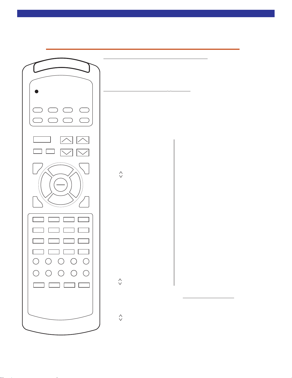
B & K CT Series MZ-128 Remote Controller Reference Sheet
The MZ-128 Remote Controller has multiple useful functions:
1) The MZ-128 Remote Controller may be used to control and setup a CT610/600310/300.
2) The learning keypads etc...
MZ-128 may be used as a source of IR for use in programming
3) The may be set to source code sets 000-128
MZ-128 the B & K IR functions listed below, for
and 999.
Setup the MZ-128 to use a discrete B & K code set:
1) Install 4 AAA batteries into the remote. Observe polarity.
2) Press and hold the B & K and MUTE buttons simultaneously for two seconds. The LED will
light up solid red and stay illuminated.
3) Firmly press the desired B & K three digit code set. Always use three digits (i.e. 0-1-1 Zone A)
4) Press the B & K button again to confirm setup. The red LED will blink three times when the IR
code has been successfully programmed.
MZ-128 Default Factory Code-Set is: 0-0-0 Whole House Control
ON
B&K
IN 4
B&K
IN 1
IN 5
IN 2
IN 6
IN 3
IN 7
MUTE
AM
FM V+ T- S-
POWER
ON/OFF
OFF
SAVE
UP
L
SEL
E
°
F
ENTER
T
DOWN
5
8
0
M
ST/M
VIDEO +
TUNE+ STA-
T+
EXIT
1 2 3
4
7
+10
TUNE-
VOLUME
Õ
®
6
9
ENTER
R
G
H
T
B+
BASSTREBLE SOURCE
B-
PRESET
MENU
I
¯
ZONE
IN 8
IN 9
D-IN
DEDICATED
LOUD
LOUDNESS
S+
STA+
CODE SET 000-128
MZ-128 BUTTON B &K IR FUNCTION
[POWER STATE]
B&K POWER ON
POWER POWER TOGGLE
OFF POWER OFF
[VOLUME]
MUTE MUTE TOGGLE
VOLUME MASTER VOL UP
VOLUME MASTER VOL DOWN
[TONE CONTROL]
B+ BASS UP
B- BASS DOWN
T+ TREBLE UP
T- TREBLE DOWN
LOUD LOUDNESS TOGGLE
[INPUT SOURCE]
S+ SOURCE UP
S- SOURCE DOWN
V+ VIDEO SOURCE UP
D-IN ZONE DEDICATED IN
AM TUNER AM
FM TUNER FM
IN 1 IN 1 OR [V1]
IN 2 IN 2 OR [V2]
IN 3 IN 3 OR [TV]
IN 4 IN 4 OR [DVD]
IN 5 IN 5 OR [CD]
IN 6 IN 6 OR [SAT]
IN 7 IN 7 OR [TAPE]
IN 8 IN 8 OR [V4]
IN 9 IN 9 OR [V5]
[FAVORITE PRESET]
PRESET FAVORITE PRESET UP
PRESET FAVORITE PRESET DN
MZ-128 BUTTON B &K IR FUNCTION
[TUNER]
AM SELECT THE AM BAND
FM SELECT THE FM BAND
TUNE + TUNE FREQUENCY UP
TUNE - TUNE FREQUENCY DOWN
STA + TUNER FAV PRESET UP
STA - TUNER FAV PRESET DOWN
M STEREO / MONO
[NAVIGATION]
MENU MENU UP/DOWN LEVEL
LEFT LEFT OR BALANCE (L)
RIGHT RIGHT OR BALANCE (R)
SEL/ENTER SELECT OR ENTER
UP UP
DOWN DOWN
SAVE SAVE
EXIT TOTAL EXIT FROM ALL MENUS
ZONE ZONE SELECT
[NUMERIC]
00
11
22
33
44
55
66
77
88
99
+10 +10
B & K Components, Ltd.
Model MZ-128
CODE SET 999
MZ-128 BUTTON B &K IR FUNCTION
[B & K ALL COMMANDS]
ON/B & K/POWER ALL B&K POWER ON
OFF ALL B&K POWER OFF
VOLUME ALL B&K VOLUME UP
VOLUME ALL B&K VOLUME DOWN
0 ALL B&K VOLUME 0 DB
2 ALL B&K VOLUME -20 DB
4 ALL B&K VOLUME -40 DB
6 ALL B&K VOLUME -60 DB
MUTE ALL B&K MUTE TOGGLE
Code-Set 128 Simply Explained
Code-Set 128 is a special code-set which
allows individual control of the Hardware Zone
that the IR Data is received by. It will not function
when received by the unit’s front panel. I.e., Two
keypads are plugged into Zone A & B’s Control
I/O Ports, when the remote comes into IR view
of the keypad in Zone A, the 128 Code-set
remote will only control Zone A, when in Zone A.
Take that same remote into Zone B and it will
only control Zone B.
Page 4
CT System Connections
RISKOF ELECTRICSHOCK
DO
NOTOPEN
B&KComponents, Ltd.
Madein the U.S.A.
IN
1
FM
ANTENNA
IN
2
IN
3
OUT
1
OUT
2
OUT
3
IN
4
IN
5
IN
6
OUT
4
OUT
5
OUT
6
IN
7
IN
8
IN
9
OUT
7
OUT
8
OUT
9
IN
A
IN
B
IN
C
OUT
A
OUT
B
OUT
C
IN
D
IN
E
IN
F
OUT
D
OUT
E
OUT
F
CAUTION: FOR CONTINUED
PROTECTION AGAINST RISK
OF FIRE REPLACE ONLY WITH
SAME TYPE AND VALUE FUSE
SPEAKEROUTPUTS
ARE
4OHM STABLE
IN
-
IN
-
COMMON
CTRL I/O
BK
&
SBIMPLY ETTER!
2
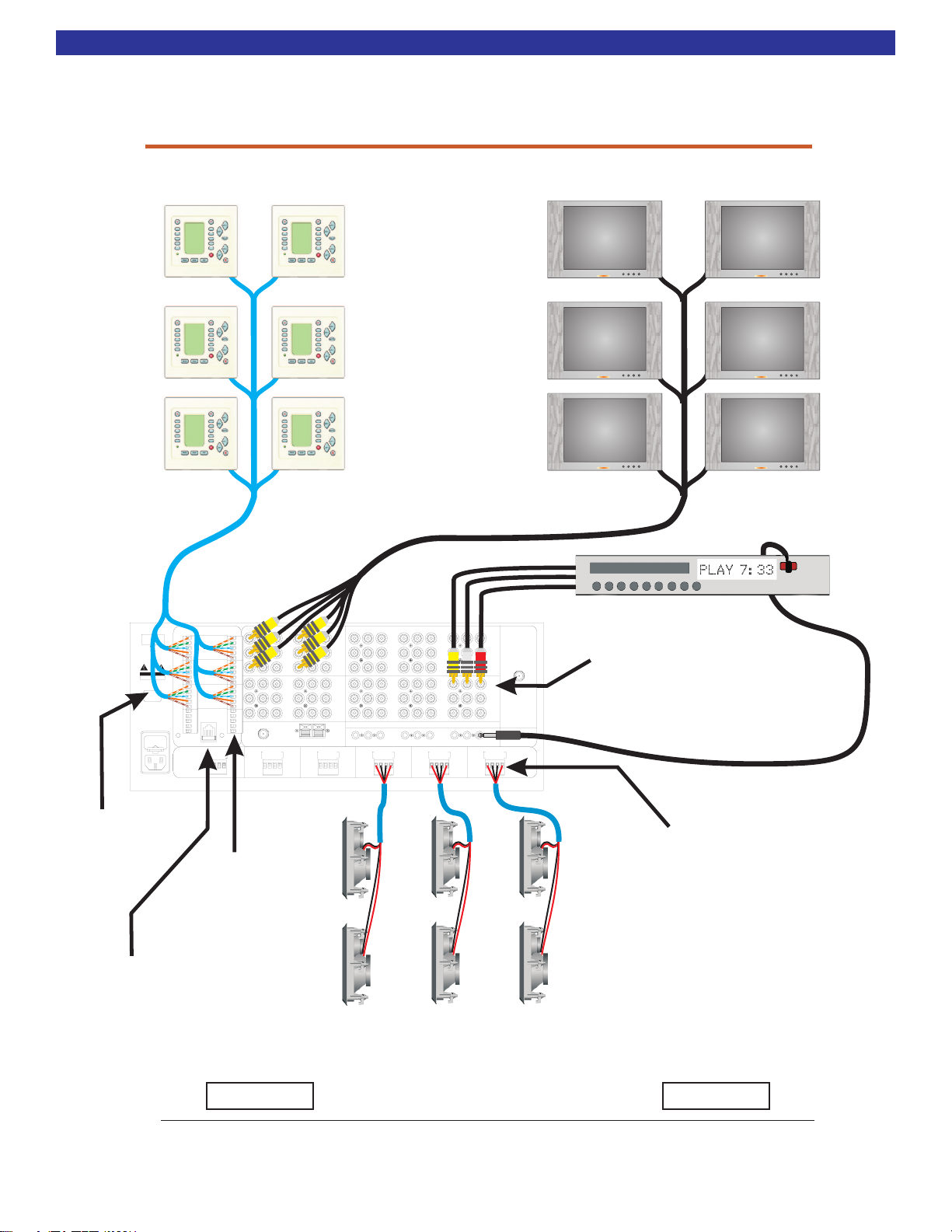
Basic CT Receiver & CK1.2 System Hookup
ZONE D
KEYPAD
ZONE E
KEYPAD
ZONE F
KEYPAD
BK
&
SBIMPLY ETTER!
B&KComponents, Ltd.
Madein the U.S.A.
www.bkcomp.com
CAUTION
RISKOF ELECTRICSHOCK
DONOT OPEN
~
AC LINE
VOLTAGE
FUSE
CAUTION: FOR CONTINUED
PROTECTION AGAINST RISK
OF FIRE REPLACE ONLY WITH
SAME TYPE AND VALUE FUSE
See page 14 of manual
for rear of
CK1.2 Keypad
&
connection diagram
to the Zone Control
I/O Ports.
CT Receiver
CONTROL
ZD
+12V
ZA
GND
RS232 XMIT
DATAIN
CTRL OUT
ZE
ZB
+12V
GND
RS232 XMIT
DATAIN
CTRL OUT
ZCZF
+12V
GND
RS232 XMIT
DATAIN
CTRL OUT
12V
12V
COMMON
GND
GND
CTRL I/O
IN
-
-
IN
IN+
IN+
OUT
OUT
OUT
2 1
RS232
ZONE F
RIGHTLEFT
-
+-+
See page 22 for
of CT Receiver &
Common Control
I/O Port connection
diagram and
Page/Event
RF REMOTE IN
ZONE E
ZONE A
KEYPAD
TV Monitor
ZONE B
KEYPAD
TV Monitor
ZONE C
OUT
6
OUT
5
OUT
4
IN
4
IN
5
IN
6
IR 5
IR 4
ZONE B
RIGHTLEFT
-
TV Monitor
C L R
IR 3
+-+
KEYPAD
A/V components connect via standard RCA
audio and video cables to the numbered
inputs of the CT Receiver.
C
ZONE LINE OUTPUTS
C
C
use.
C
OUT
C
F
OUT
C
E
OUT
D
IN
D
IN
E
IN
F
AM ANTENNA
ZONE D
RIGHTLEFT
-
+-+
RIGHTLEFT
-
OUT
C
OUT
B
OUT
A
IN
A
IN
B
IN
C
IR 9
+-+
BUFFERED A/V SOURCE OUTPUTS
OUT
9
OUT
8
OUT
7
IN
7
IN
8
IN
9
A/VSOURCEINPUTS
IR 8
IR 6
IR 7
ZONE C
RIGHTLEFT
-
+-+
rear
Zone D
ZoneE
Zone F
OUT
3
OUT
2
OUT
ANTENNA
1
IN
1
IN
2
IN
3
SPEAKEROUTPUTS
ARE4 OHM STABLE
IR 1IR 2
ZONE A
RIGHTLEFT
-
+-+
Zone A
TV Monitor
Zone B
TV Monitor
Zone C
TV Monitor
INPUT 1
See page 17 of manual for
FM
rear of CT Receiver &
source connection diagram
IR Flashers for A/V components
are connected to the IR output
corresponding to their A/V Input #.
IR FLASHER 1
See page 12 of the manual
for rear of CT Receiver &
Speaker connection diagram
See page 32 of the manual for
rear of CT Receiver &
RS232
Port connection diagram for
BKcSuite.
WARNING!
ALL WORK SHOULD BE DONE BY A QUALIFIED/TRAINED PROFESSIONAL.
ZONE C SPEAKERS
ZONE B SPEAKERS
ZONE A SPEAKERS
UNPLUG AC POWER FROM ALL UNITS
BEFORE MAKING ANY CONNECTIONS
WARNING!
Page 5

CK1.2 Keypad Hookup
RISKOF ELECTRIC SHOCK
DO
NOTOPEN
B&K Components, Ltd.
Made in the U.S.A.
IN
1
FM
ANTENNA
IN
2
IN
3
OUT
1
OUT
2
OUT
3
IN
4
IN
5
IN
6
OUT
4
OUT
5
OUT
6
IN
7
IN
8
IN
9
OUT
7
OUT
8
OUT
9
IN
A
IN
B
IN
C
OUT
A
OUT
B
OUT
C
IN
D
IN
E
IN
F
OUT
D
OUT
E
OUT
F
CAUTION: FOR CONTINUED
PROTECTION AGAINST RISK
OF FIRE REPLACE ONLY WITH
SAME TYPE AND VALUE FUSE
SPEAKER OUTPUTS
ARE
4 OHM STABLE
IN
-
IN
-
COMMON
CTRL I/O
3
CT610
CK1.2 Keypad
Example Connection of a CK1.2 Keypad to a CT Receiver
CK1.2 Keypad Connection
Plug the male RJ45 connector into the
[IN] RJ45
port on the CK1.2 Keypad. Additional
keypads in a zone can be run out of the Slave [OUT].
Using a EIA-T568B Cat-5 Cable
RJ45 termination on one end
and bare wire on the other
First Color is Primary Color (Secondary)
A
IT
+12V - Orange / White Stripe & (Solid Brown)
GROUND - Green / White Stripe & (Solid Green)
RS232 XMIT - White / Blue Stripe
IR OUTPUT - Solid Orange
Master
FUSE
CAUTION: FOR CONTINUED
PROTECTION AGAINST RISK
OF FIRE REPLACE ONLY WITH
SAME TYPE AND VALUE FUSE
BK&
SBIMPLY ETTER!
B&K Components, Ltd.
Made in the U.S.A.
www.bkcomp.com
CAUTION
RISKOF ELECTRIC SHOCK
DONOT OPEN
~
AC LINE
VOLTAGE
12V Control - White / Brown Stripe
CONTROL
ZD
ZE
12V
GND
IN
IN +
OUT
OUT
21
+12V
ZA
GND
RS232 XMIT
DATA IN
CTRL OUT
ZB
+12V
GND
RS232 XMIT
DATA IN
CTRL OUT
ZCZF
+12V
GND
RS232 XMIT
DATA IN
CTRL OUT
12V
COMMON
GND
CTRL I/O
IN
RS232
ZONE F
-
IN +
OUT
RF REMOTE IN
RIGHTLEFT
-+-
+
-
Solid Blue = N/C
CT Receiver Connection
Insert and tighten the wires into the specific
Hardware Zone
Control I/O Port Phoenix
plug of the Zone that you wish to control.
ZONE LINE OUTPUTS
OUT
F
OUT
E
ZONE E
RIGHTLEFT
OUT
D
IN
D
IN
E
IN
F
-+-
+
AM ANTENNA
ZONE D
RIGHTLEFT
OUT
C
OUT
B
OUT
A
IN
A
IN
B
IN
C
IR 9
-+-
+
BUFFERED A/V SOURCE OUTPUTS
OUT
9
OUT
8
IR 8
OUT
7
IN
7
IN
8
IN
9
A/V SOURCE INPUTS
IR 7
ZONE C
RIGHTLEFT
-+-
+
IR 6
IR 5
IR 1IR 2
OUT
3
OUT
2
OUT
1
IN
1
IN
2
IN
3
SPEAKER OUTPUTS
ARE 4 OHM STABLE
ZONE A
RIGHTLEFT
-+-
+
FM
ANTENNA
OUT
6
OUT
5
OUT
IR 4
ZONE B
4
IN
4
IN
5
IN
6
IR 3
RIGHTLEFT
-+-
+
DO NOT CONNECT KEYPADS TO COMMON CONTROL I/O PORTS.
Page 6

Shared Source Connections
RISKOF ELECTRIC SHOCK
DO
NOTOPEN
B&K Components, Ltd.
Made in the U.S.A.
IN
1
FM
ANTENNA
IN
2
IN
3
OUT
1
OUT
2
OUT
3
IN
4
IN
5
IN
6
OUT
4
OUT
5
OUT
6
IN
7
IN
8
IN
9
OUT
7
OUT
8
OUT
9
IN
A
IN
B
IN
C
OUT
A
OUT
B
OUT
C
IN
D
IN
E
IN
F
OUT
D
OUT
E
OUT
F
CAUTION: FOR CONTINUED
PROTECTION AGAINST RISK
OF FIRE REPLACE ONLY WITH
SAME TYPE AND VALUE FUSE
SPEAKER OUTPUTS
ARE
4 OHM STABLE
IN
-
IN
-
COMMON
CTRL I/O
4
Source
Example connection of a Shared Source to a CT Receiver
BK&
SBIMPLY ETTER!
B&K Components, Ltd.
Made in the U.S.A.
www.bkcomp.com
CAUTION
RISKOF ELECTRIC SHOCK
DONOT OPEN
~
AC LINE
VOLTAGE
FUSE
CAUTION: FOR CONTINUED
PROTECTION AGAINST RISK
OF FIRE REPLACE ONLY WITH
SAME TYPE AND VALUE FUSE
CONTROL
ZD
ZE
12V
GND
IN
IN +
OUT
OUT
21
+12V
ZA
GND
RS232 XMIT
DATA IN
CTRL OUT
ZB
+12V
GND
RS232 XMIT
DATA IN
CTRL OUT
ZCZF
+12V
GND
RS232 XMIT
DATA IN
CTRL OUT
12V
COMMON
GND
CTRL I/O
IN
RS232
ZONE F
-
IN +
OUT
RIGHTLEFT
-+-
+
-
CT Receiver Connection
Plug the analog audio,
composite video, and the
IR Emitter into the back panel.
ZONE LINE OUTPUTS
RF REMOTE IN
ZONE E
RIGHTLEFT
BUFFERED A/V SOURCE OUTPUTS
OUT
9
OUT
8
OUT
7
IN
7
IN
8
IN
9
A/V SOURCE INPUTS
IR 7
ZONE C
RIGHTLEFT
-+-
+
IR 6
IR 5
ZONE D
RIGHTLEFT
OUT
C
OUT
B
OUT
-+-
A
IN
A
IN
B
IN
C
+
IR 9
IR 8
OUT
F
OUT
E
OUT
D
IN
D
IN
E
IN
F
AM ANTENNA
-+-
+
IR 4
OUT
OUT
OUT
IN
IN
IN
ZONE B
RIGHTLEFT
6
5
4
4
5
6
-+-
+
CLR
IR 3
OUT
3
OUT
2
OUT
1
IN
1
IN
2
IN
3
IR 1IR 2
ZONE A
RIGHTLEFT
-+-
FM
ANTENNA
SPEAKER OUTPUTS
ARE 4 OHM STABLE
+
Mount IR Emitter on
the front of the source
in front of the IR receptor
~
AC LINE
DVD Connection
Use the analog audio and composite video
from the source. The CT Receiver can
process analog audio and composite video
signals. Digital processing N/A.
DIGITAL OUT
OPTICAL
COAX
COMPONENT
VIDEO OUT
CL
YPBP
COMP
VIDEO
OUT
R
R
LR
AUDIO
Page 7

Speaker Conncetions
RISKOF ELECTRIC SHOCK
DO
NOTOPEN
B&K Components, Ltd.
Made in the U.S.A.
IN
1
FM
ANTENNA
IN
2
IN
3
OUT
1
OUT
2
OUT
3
IN
4
IN
5
IN
6
OUT
4
OUT
5
OUT
6
IN
7
IN
8
IN
9
OUT
7
OUT
8
OUT
9
IN
A
IN
B
IN
C
OUT
A
OUT
B
OUT
C
IN
D
IN
E
IN
F
OUT
D
OUT
E
OUT
F
CAUTION: FOR CONTINUED
PROTECTION AGAINST RISK
OF FIRE REPLACE ONLY WITH
SAME TYPE AND VALUE FUSE
SPEAKER OUTPUTS
ARE
4 OHM STABLE
IN
-
IN
-
COMMON
CTRL I/O
5
CT Receiver
speaker output
Speaker
Example connection of Speakers to a CT Receiver
BK&
SBIMPLY ETTER!
B&K Components, Ltd.
Made in the U.S.A.
www.bkcomp.com
CAUTION
RISKOF ELECTRIC SHOCK
DONOT OPEN
~
AC LINE
VOLTAGE
FUSE
CAUTION: FOR CONTINUED
PROTECTION AGAINST RISK
OF FIRE REPLACE ONLY WITH
SAME TYPE AND VALUE FUSE
CONTROL
ZD
ZE
12V
GND
IN
IN +
OUT
OUT
21
+12V
ZA
GND
RS232 XMIT
DATA IN
CTRL OUT
ZB
+12V
GND
RS232 XMIT
DATA IN
CTRL OUT
ZCZF
+12V
GND
RS232 XMIT
DATA IN
CTRL OUT
12V
COMMON
GND
CTRL I/O
IN
RS232
ZONE F
-
IN +
OUT
RIGHTLEFT
-+-
+
-
ZONE LINE OUTPUTS
RF REMOTE IN
ZONE E
RIGHTLEFT
BUFFERED A/V SOURCE OUTPUTS
OUT
9
OUT
8
OUT
7
IN
7
IN
8
IN
9
A/V SOURCE INPUTS
IR 7
ZONE C
RIGHTLEFT
-+-
+
IR 6
ZONE D
RIGHTLEFT
OUT
C
OUT
B
OUT
-+-
A
IN
A
IN
B
IN
C
+
IR 9
IR 8
OUT
F
OUT
E
OUT
D
IN
D
IN
E
IN
F
AM ANTENNA
-+-
+
IR 5
IR 4
OUT
OUT
OUT
IN
IN
IN
ZONE B
RIGHTLEFT
6
5
4
4
5
6
IR 3
-+-
+
OUT
3
OUT
2
OUT
1
IN
1
IN
2
IN
3
IR 1IR 2
ZONE A
RIGHTLEFT
-+-
FM
ANTENNA
SPEAKER OUTPUTS
ARE 4 OHM STABLE
+
ZONE F
LEFT
+
RIGHT
- -
+
[R+] Right Positive Speaker Output (Red Wire)
[R-] Right Negative Speaker Output (Black Wire)
[L-] Left Negative Speaker Output (Black Wire)
[L+] Left Positive Speaker Output (Red Wire)
Page 6
Page 8

Common Control Trigger Connections
RISKOF ELECTRIC SHOCK
DO
NOTOPEN
B&K Components, Ltd.
Made in the U.S.A.
IN
1
FM
ANTENNA
IN
2
IN
3
OUT
1
OUT
2
OUT
3
IN
4
IN
5
IN
6
OUT
4
OUT
5
OUT
6
IN
7
IN
8
IN
9
OUT
7
OUT
8
OUT
9
IN
A
IN
B
IN
C
OUT
A
OUT
B
OUT
C
IN
D
IN
E
IN
F
OUT
D
OUT
E
OUT
F
CAUTION: FOR CONTINUED
PROTECTION AGAINST RISK
OF FIRE REPLACE ONLY WITH
SAME TYPE AND VALUE FUSE
SPEAKER OUTPUTS
ARE
4 OHM STABLE
IN
-
IN
-
COMMON
CTRL I/O
6
Doorbell trigger
Camera input
Example of ommon Control trigger with a CTa C Receiver
BK
&
SBIMPLY ETTER!
B&K Components, Ltd.
Made in the U.S.A.
www.bkcomp.com
CAUTION
RISKOF ELECTRIC SHOCK
DONOT OPEN
~
AC LINE
VOLTAGE
FUSE
CAUTION: FOR CONTINUED
PROTECTION AGAINST RISK
OF FIRE REPLACE ONLY WITH
SAME TYPE AND VALUE FUSE
ZD
ZE
12V
GND
IN
-
IN +
OUT
OUT
21
CONTROL
+12V
GND
RS232 XMIT
DATA IN
CTRL OUT
+12V
GND
RS232 XMIT
DATA IN
CTRL OUT
+12V
GND
RS232 XMIT
DATA IN
CTRL OUT
COMMON
CTRL I/O
RS232
ZONE F
RIGHTLEFT
GND
OUT
ZONE LINE OUTPUTS
ZONE E
OUT
F
OUT
E
OUT
D
IN
D
IN
E
IN
F
AM ANTENNA
RIGHTLEFT
-+-
+
ZA
ZB
ZCZF
12V
IN
-
IN +
-+-
+
RF REMOTE IN
ZONE D
OUT
C
OUT
B
OUT
A
IN
A
IN
B
IN
C
C
IR 9
RIGHTLEFT
-+-
+
BUFFERED A/V SOURCE OUTPUTS
OUT
9
OUT
8
IR 8
OUT
7
IN
7
IN
8
IN
9
A/V SOURCE INPUTS
IR 7
ZONE C
RIGHTLEFT
-+-
+
IR 6
IR 5
IR 4
OUT
OUT
OUT
ZONE B
OUT
6
5
4
IN
4
IN
5
IN
6
IR 3
RIGHTLEFT
-+-
+
3
OUT
2
OUT
1
IN
1
IN
2
IN
3
IR 1IR 2
ZONE A
RIGHTLEFT
-+-
FM
ANTENNA
SPEAKER OUTPUTS
ARE 4 OHM STABLE
+
Common Control Connection
Connect the wires for the trigger
[IN -] & [IN +] terminals
to the
on the
The Page/Event is initiated by
detectionofupto
5 position Phoenix plug.
24V AC or DC.
Push Doorbell
Trigger
Doorbell
Transformer
(16VAC)
Example:
Connect Common
Control 1 to a doorbell
to trigger a Page/Event
Page/Event 1
By default w
hen Common Control 1 is
triggered by pushing the doorbell, the
CT Receiver
will switch to
INPUT 8.
Page 9

PC Interface Connection
RISKOF ELECTRIC SHOCK
DO
NOTOPEN
B&K Components, Ltd.
Made in the U.S.A.
IN
1
FM
ANTENNA
IN
2
IN
3
OUT
1
OUT
2
OUT
3
IN
4
IN
5
IN
6
OUT
4
OUT
5
OUT
6
IN
7
IN
8
IN
9
OUT
7
OUT
8
OUT
9
IN
A
IN
B
IN
C
OUT
A
OUT
B
OUT
C
IN
D
IN
E
IN
F
OUT
D
OUT
E
OUT
F
CAUTION: FOR CONTINUED
PROTECTION AGAINST RISK
OF FIRE REPLACE ONLY WITH
SAME TYPE AND VALUE FUSE
SPEAKER OUTPUTS
ARE
4 OHM STABLE
IN
-
IN
-
COMMON
CTRL I/O
7
***Warning - PC requirements - 128MB RAM, Pentium grade or better processor, Windows 98SE operating
system or greater. (Exception - BKcSuite not supported on Windows NT) ***
Connect the CT/CK/SR product’s programing cord to the PC’s serial port DB-9 (Not ethernet or network).
Be sure to select “Local Com” in BKcSuite, as “Network” is currently unsupported.
If the unit will not communicate using RS-232, perform a factory reset.
Disable all other programs when using BKcSuite for setup of any B&K product.
Example connecting a laptop computer to a CT Receiver
BK
&
SBIMPLY ETTER!
B&K Components, Ltd.
Made in the U.S.A.
www.bkcomp.com
CAUTION
RISKOF ELECTRIC SHOCK
DONOT OPEN
~
AC LINE
VOLTAGE
FUSE
CAUTION: FOR CONTINUED
PROTECTION AGAINST RISK
OF FIRE REPLACE ONLY WITH
SAME TYPE AND VALUE FUSE
CONTROL
ZD
ZE
12V
GND
IN
IN +
OUT
OUT
21
+12V
ZA
GND
RS232 XMIT
DATA IN
CTRL OUT
ZB
+12V
GND
RS232 XMIT
DATA IN
CTRL OUT
ZCZF
+12V
GND
RS232 XMIT
DATA IN
CTRL OUT
12V
COMMON
GND
CTRL I/O
IN
OUT
-
IN +
-
RS232
ZONE F
RIGHTLEFT
-+-
+
CT Reciever Connection
Plug one end of the RJ-45 terminated
CAT5 into the main RJ-45 Jack labeled
RS-232 on the back panel.
ZONE LINE OUTPUTS
RF REMOTE IN
ZONE E
RIGHTLEFT
OUT
OUT
OUT
OUT
OUT
OUT
C
B
A
IN
A
IN
B
IN
C
F
E
D
IN
D
IN
E
IN
F
OUT
OUT
OUT
9
8
7
IN
7
IN
8
IN
9
OUT
OUT
OUT
6
5
4
IN
4
IN
5
IN
6
OUT
OUT
OUT
3
2
FM
ANTENNA
1
IN
1
IN
2
IN
3
BUFFERED A/V SOURCE OUTPUTS
A/V SOURCE INPUTS
SPEAKER OUTPUTS
IR 9
IR 8
IR 7
ZONE C
RIGHTLEFT
-+-
AM ANTENNA
ZONE D
RIGHTLEFT
-+-
+
-+-
+
IR 5
IR 6
+
Computer Connection
Plug one end of the RJ-45 terminated
CAT5 cable into the serial communications
port on the back of the computer
using the serial DB9 to RJ-45 adaptor.
IR 4
ZONE B
IR 3
IR 1IR 2
RIGHTLEFT
-+-
+
ZONE A
RIGHTLEFT
ARE 4 OHM STABLE
-+-
+
OR
USB to Serial Adaptor
USB to serial adaptors can be a convenient
solution for connecting to a computer with
no available serial ports. Install the required
drivers and then verify what com port the USB
adaptor is on. Once your com settings are
determined, configure the BKcSuite and B & K
CK1.2 / SR10.1 Editors for simple and easy setup.
Page 10

BKcSuite Tabs 1 & 2
8
BKcSuite Basic Mode Tab1&Tab2Explained
Power On Preference - Video From
Each Zone can be configured to
automatically switch to a specific
source’s video signal when that
Zone is powered ON.
Power On Preference - Audio From
Each Zone can be
automatically switch
source’s audio signal when
that Zone is powered ON.
Room Names
Each room can have its own
user-friendly
name.
That name is displayed
on the Front Panel and the unit’s
On-Screen-Display.
(11 character limit)
Input Names
Each input can have its own
user-friendly custom/intuitive
name. That name
on the Front Panel and the unit’s
On-Screen-Display.
(5 character limit)
configured to
to a specific
custom/intuitive
is displayed
Basic Setup
Zone Setup
Rear Panel
Silkscreen
Zone A
Zone A
Zone B
Zone B
Zone C
Zone C
Zone D
Zone D
Zone E
Zone E
Zone F
Zone F
Input Setup
Rear Panel
Silkscreen
IN 1
IN 2
IN 3
IN 4
IN 5
IN 6
Room
Name
Power On Title 1
Input
Name
IN 1
IN 2
IN 3
IN 4
IN 5
IN 6
Power On Preference - Volume
Each Zone can be configured to
automatically switch to a specific
volume level when that Zone is
powered ON.
Keypad Feedback
Last
Last
Used
FM
FM
FM
FM
FM
FM
Multi Zone
Common Zone Inputs
Rear Panel
Silkscreen
IN 7
IN 8
IN 9
Audio
From
IN 7
IN 8
IN 9
Input
Name
Used
Video
From
IN 1
IN 1
IN 1
IN 1
IN 1
IN 1
Power On Title 2
Last
Power On
Used
Volu me
-46 dB
-46 dB
-46 dB
-46 dB
-46 dB
-46 dB
Basic Operation
Dedicated Zone Inputs D-IN
Rear Panel
Silkscreen
IN A
IN B
IN C
IN D
IN E
IN F
Power
On AM
Open
Open
Open
Open
Open
Open
IN A
IN B
IN C
IN D
IN E
IN F
Input
Name
Power On Preference - Tuner Frequency
When a Zone is set to Power-On with
Tuner (AM or FM), you can set the Tuner
to a specific frequency when that Zone
is powered ON.
Power
On FM
Open
Open
Open
Open
Open
Open
Power On Titles
A customizable 2-line Power Up
Title can be set for the customer.
Dedicated Input Names
Each dedicated input can have its
own user-friendly custom/intuitive
name. That name is displayed
on the Front Panel and the unit’s
On-Screen-Display.
(5 character limit)
Keypad Main Page # 1
MAIN
IN 1
IN 6
IN 2
IN 7
IN 3
IN 8
IN 9
IN 4
FM
IN 5
PAGE 1
Keypad feedback is used to
keep the
source and
keypad on the proper
page. It insures the
user has direct operation of the
current source selected.
To keep the keypad feedback
feature functioning correctly,
you must match the devices
on the keypad buttons (you
created in the CK1.2 editor)
with the devices set for each
location in the Basic Setup
Page of the BKcSuite software.
Basic Setup
Main Menu Page 1 Main Menu Page 2
D6
D10
IN 6 (IN 6)
D7
IN 7 (IN 7)
D8
IN 8 (IN 8)
D9
IN 9 (IN 9)
FM (FM)
IN 1 (IN 1)
IN 2 (IN 2)
IN 3 (IN 3)
IN 4 (IN 4)
IN 5 (IN 5)
Keypad Feedback
D1
D2
D3
D4
D5
D16
D17
D18
D19
D20
None
None
None
None
None
D-IN (D-IN)
AM (AM)
None
None
None
D11
D12
D13
D14
D15
Keypad Main Page # 2
MAIN
D-IN
AM
ID128
PAGE 2
Keypad feedback can be turned off
by choosing the option of “NONE”.
Page 11

Home Theater and CT Products
RISKOF ELECTRIC SHOCK
DO
NOTOPEN
B&K Components, Ltd.
Made in the U.S.A.
IN
1
FM
ANTENNA
IN
2
IN
3
OUT
1
OUT
2
OUT
3
IN
4
IN
5
IN
6
OUT
4
OUT
5
OUT
6
IN
7
IN
8
IN
9
OUT
7
OUT
8
OUT
9
IN
A
IN
B
IN
C
OUT
A
OUT
B
OUT
C
IN
D
IN
E
IN
F
OUT
D
OUT
E
OUT
F
CAUTION: FOR CONTINUED
PROTECTION AGAINST RISK
OF FIRE REPLACE ONLY WITH
SAME TYPE AND VALUE FUSE
SPEAKER OUTPUTS
ARE
4 OHM STABLE
IN
-
IN
-
COMMON
CTRL I/O
9
CT600
Integration of a B & K Home Theater and
a CT together as a Complete SystemReceiver
B&K surround processor Input Connection
S lug the analog audio and composite
ince the CT Receiver does not handle digital or S-Video signals, p
video directly into the source input section from the buffered outputs of the CT Reciever.
Directly connect the Digital and S-Video output signals from the DVD player to the theater processor
.
FUSE
CAUTION: FOR CONTINUED
PROTECTION AGAINST RISK
OF FIRE REPLACE ONLY WITH
SAME TYPE AND VALUE FUSE
RISKOF ELECTRIC SHOCK
~
AC LINE
VOLTAGE
CAUTION
DONOT OPEN
IEEE
1394
RIGHT
SURR BACK
Source Connection
Plug the analog audio and
composite video outputs from
the DVD Player into the
A/V Source Input section.
ZD
ZE
~
12V
GND
IN
IN +
OUT
OUT
2
BK
&
SB
IMPLY ETTER!
B&K Components, Ltd.
Made in the U.S.A.
www.bkcomp.com
CAUTION
RISKOF ELECTRIC SHOCK
DONOT OPEN
AC LINE
VOLTAGE
FUSE
CAUTION: FOR CONTINUED
PROTECTION AGAINST RISK
OF FIRE REPLACE ONLY WITH
SAME TYPE AND VALUE FUSE
COAX DIGITAL
CONTROL OUT IR IN
1
2
12VDC
50mA
+
3
4
RIGHT
SURROUND
CONTROL
+12V
GND
RS232 XMIT
DATA IN
CTRL OUT
+12V
GND
RS232 XMIT
DATA IN
CTRL OUT
+12V
GND
RS232 XMIT
DATA IN
CTRL OUT
COMMON
CTRL I/O
-
RS232
ZONE F
OPTICAL DIGITAL
V1ZA OUT V2TV
D
BK
&
SB
IMPLY ETTER!
DVDZB OUT CDSAT
ZA
RS-232
ZB
RIGHT FRONT LEFT FRONT
ZA
ZB
ZCZF
12V
GND
IN
-
IN +
OUT
1
RIGHTLEFT
-+-
+
DVDCDSATOUT
DVD-AUDIO IN
SUB CENTER
BALANCED SURROUND OUTPUTS
CENTER
ZONE LINE OUTPUTS
RF REMOTE IN
ZONE E
V1
V2
ZA AUDIO OUT
SUB CENTER
ZA
LEFT
SURROUND
ZB/V2
V1
LINE OUTPUTSSBACKFRONTSURRFRONTSURR
LEFT
SURR BACK
Audio/Video Systems Made in the U.S.A.
SUBWOOFER
CDTAPEZB TVSAT
RIGHT
DVDTAPE
LINE INPUTS
Buffered Output Connection
Plug the analog audio and composite video
into the CT Receiver buffered output section.
This analog buffered output will be used to “share”
the source with the theater processor without
any signal degradation.
BUFFERED A/V SOURCE OUTPUTS
ZONE D
OUT
C
OUT
B
OUT
A
IN
A
IN
B
IN
C
IR 9
RIGHTLEFT
-+-
+
OUT
F
OUT
E
OUT
D
IN
D
IN
E
IN
F
AM ANTENNA
RIGHTLEFT
-+-
+
IR 8
IR 7
ZONE C
OUT
9
OUT
8
OUT
7
IN
7
IN
8
IN
9
RIGHTLEFT
-+-
+
A/V SOURCE INPUTS
IR 5
IR 6
IR 4
CD
ON
OFF
OUT
OUT
OUT
ZONE B
6
5
4
IN
4
IN
5
IN
6
RIGHTLEFT
-+-
V1
V2
BALANCED INPUTS
LEFT
CLR
CLR
IR 3
IR 1IR 2
+
IN 1
S
C
L
R
RIGHT
OUT
3
R
OUT
2
OUT
1
IN
1
IN
2
IN
3
ZONE A
COMPONENT VIDEO
IN 3
IN 2
www.bkcomp.com
AM FM
ANTENNA
DVD
ON
OFF
LEFT
FM
ANTENNA
SPEAKER OUTPUTS
ARE 4 OHM STABLE
RIGHTLEFT
-+-
+
OUT
CT SERIES IR CODES MATCH
HOME THEATER INPUT CODES
AS DEFINED IN TABLE BELOW.
MULTI-ZONE
INPUT 1
INPUT 2
INPUT 3
INPUT 4
INPUT 5
INPUT 6
INPUT 7
Page 7 in User Manual.
HOME THEATER
=
=
=
=
=
=
=
V1
V2
TV
DVD
CD
SAT
TAPE
RS232 Interface
Connect the RS-232 from the
CT Receiver to the RS-232
of the theater processor with
a B&K RS-232 cable
swapped
provided from B&K by request.
This cable keeps synchronization
between the CT and the home
theater unit.
Page 27 in User Manual.
DVD Connection
Connect analog audio and composite video to the CT Receiver
first before sending the signal to home theater. The CT Receiver
can only process analog audio and composite video signals.
Directly connect the Digital and S-Video output signals
from the DVD player to the theater processor.
Page 17 in User Manual.
DIGITAL OUT
OPTICAL
COAX
COMPONENT
VIDEO OUT
CLR
Y
S
COMP
VIDEO
D
OUT
PRP
B
LR
AUDIO
Page 12

RISK OF ELECTRICSHOCK
DO
NOT OPEN
B&K Components, Ltd.
Made in the U.S.A.
WS S B .E IMPLY OUND ETTER
IN
1
FM
ANTENNA
IN
2
IN
3
OUT
1
OUT
2
OUT
3
IN
4
IN
5
IN
6
OUT
4
OUT
5
OUT
6
IN
7
IN
8
IN
9
OUT
7
OUT
8
OUT
9
IN
A
IN
B
IN
C
OUT
A
OUT
B
OUT
C
IN
D
IN
E
IN
F
OUT
D
OUT
E
OUT
F
CAUTION: FOR CONTINUED
PROTECTION AGAINST RISK
OF FIRE REPLACE ONLY WITH
SAME T YPE AND VALUE FUSE
IN
-
SPEAKER OUTPUTS
ARE
4 OHM STABLE
FM Antenna - F-type connector
IN
-
CT610/310 - 2 tuners
CT600/300 - 1 - tuner
Page 23 in User Manual.
uffered
A/V Buffered Source Outputs -
9 b analog L/R audio and
used for
composite video outputs
onnecting multiple A/V products.
c
Page 18 in User Manual.
11.9.04
FM
ANTENNA
2
3
OUT
OUT
6
OUT
OUT
OUT
4
5
OUT
IN
IN
4
IN
IN
1
1
2
3
IN
5
6
IN
ARE 4 OHM STABLE
SPEAKER OUTPUTS
+
-
RIGHTLEFT
-
ZONE A
+
Zone Speaker Outputs -
4 position Phoenix plug
Supports 10 gauge speaker
wire max. Speaker outputs
are 4 ohm stable.
IR 1IR 2
Page 12 in User Manual.
DATA IN
IR 3
+
-
RIGHTLEFT
-
ZONE B
+
IR 4
IR 5
(1/8" mini jack)
IR Flasher Outputs -
9 Flasher
outputs that route IR
data to individual source
gear from Zone
or the front panel IR
Receiver.
Page 18 in User Manual.
Shared A/V Source Inputs -
9 analog L/R audio and composite video.
Page 17 in User Manual.
Dedicated A/V Zone Inputs -
Each zone has a dedicated A/V
CT Info SheetReceiver
factory
Zone Line Outputs -
Each zone has an A/V line level output
( default setup is configured to FIXED)
Page 19 in User Manual.
input (Dedicated) specific to
that zone, no other zone may
ZD/ZE/ZF/CC2 = 1 CARD
select this input.
Page 20 in User Manual.
9
OUT
BUFFERED A/V SOURCE OUTPUTS
C
OUT
F
OUT
ZONE LINE OUTPUTS
ZA
GND
+12V
CONTROL
RS232 XMIT
OUT
OUT
OUT
DATA IN
8
B
E
CTRL OUT
ZB
+12V
OUT
OUT
OUT
GND
7
A
D
DATA IN
RS232 XMIT
IN
IN
IN
CTRL OUT
7
A
D
ZCZF
+12V
GND
IN
IN
IN
RS232 XMIT
8
A/V SOURCE INPUTS
9
IN
B
C
IN
F
E
IN
-
12V
IN
GND
DATA IN
COMMON
CTRL OUT
CTRL I/O
IR 6
+
-
RIGHTLEFT
-
IR 7
ZONE C
+
IR 8
IR 9
+
-
RIGHTLEFT
-
ZONE D
+
AM ANTENNA
+
-
RIGHTLEFT
-
ZONE E
+
RF REMOTE IN
1
IN +
OUT
+
-
RIGHTLEFT
-
ZONE F
+
RF Remote IN
RS232
AM antenna
Not Supported.
Common Control I/O Port - 5 pos. Phoenix plug
1A total maximum current per control card: ZA/ZB/ZC/CC1 = 1 CARD
connection.
Page 23 in Manual
ZD/ZE/ZF/CC2=1CARD
12V 12 Volt power source
GND Ground connection
IN - / IN + Programmable input (detection of up to 24VAC / 24VDC)
volume muting in selected zones etc.)
i.e. doorbell trigger (select a security camera input or
CTRL OUT Programmable (12VDC 200mA max per each Control Out)
Page 22 and 48 in User Manual.
Zone Control I/O (CK1.2 Keypad) Port - 5 pos. Phoenix plug
1A total maximum current per control card: ZA/ZB/ZC/CC1=1CARD
12V 12 Volt power source
GND Ground connection
RS232 XMIT Transmits RS232 data
DATA IN IR input for keypads
CTRL OUT Programmable (12VDC 200mA max per each Control Out)
Page 14 in User Manual.
ZD
B&K
WS S B .E IMPLY OUND ETTER
B&K Components, Ltd.
www.bkcomp.com
Made in the U.S.A.
RS232 - 2 way communication
using BKC-DIP or BKcSuite
Software.
AC fuse location.
AC input module
Page 33 and 54 in User
Page 12 in User
Manual.
12V
GND
FUSE
CAUTION: FOR CONTINUED
-
2
IN
IN +
OUT
PROTECTION AGAINST RISK
OF FIRE REPLACE ONLY WITH
SAME T YPE AND VALUE FUSE
ZE
DO NOT OPEN
CAUTION
RISK OF ELECTRICSHOCK
~
AC LINE
VOLTAGE
 Loading...